process intensification in spatial domain - ocw.tudelft.nl · msc course on process...
TRANSCRIPT
1MSc Course on Process Intensification
STRUCTUREProcess Intensification in Spatial Domain
2MSc Course on Process Intensification
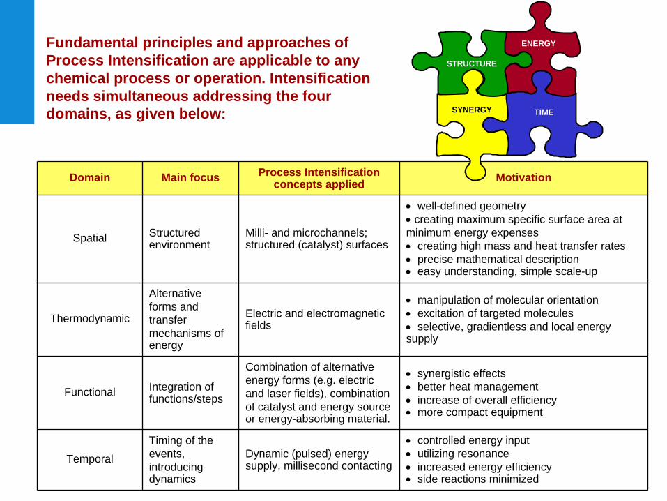
Fundamental principles and approaches of Process Intensification are applicable to any chemical process or operation. Intensification needs simultaneous addressing the four domains, as given below:
Domain Main focus Process Intensification concepts applied Motivation
Spatial Structured environment
Milli- and microchannels; structured (catalyst) surfaces
well-defined geometry
creating maximum specific surface area at minimum energy expenses creating high mass and heat transfer rates precise mathematical description easy understanding, simple scale-up
Thermodynamic
Alternative forms and transfer mechanisms of energy
Electric and electromagnetic fields
manipulation of molecular orientation excitation of targeted molecules
selective, gradientless and local energy supply
Functional Integration of functions/steps
Combination of alternative energy forms (e.g. electric and laser fields), combination of catalyst and energy source or energy-absorbing material.
synergistic effects better heat management increase of overall efficiency more compact equipment
Temporal
Timing of the events, introducing dynamics
Dynamic (pulsed) energy supply, millisecond contacting
controlled energy input utilizing resonance increased energy efficiency side reactions minimized
STRUCTURE
TIMESYNERGY
ENERGY
3MSc Course on Process Intensification
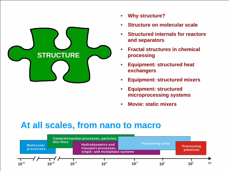
STRUCTURE
• Why structure?
• Structure on molecular scale
• Structured internals for reactors and separators
• Fractal structures in chemical processing
• Equipment: structured heat exchangers
• Equipment: structured mixers
• Equipment: structured microprocessing systems
• Movie: static mixers
10-16 10-10 10--6 10-4 10-2 100 102 m
Molecular processes
Catalyst/reaction processes, particles, thin films Processing units
Processing plant/site
Hydrodynamics andtransport processes,single- and multiphase systems
At all scales, from nano to macro
4MSc Course on Process Intensification
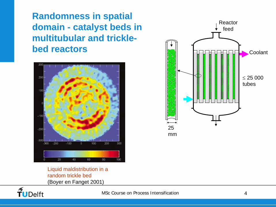
Randomness in spatial domain - catalyst beds in multitubular and trickle- bed reactors
25 mm
25 000 tubes
Reactor feed
Coolant
Liquid maldistribution in a random trickle bed(Boyer en Fanget 2001)
5MSc Course on Process Intensification
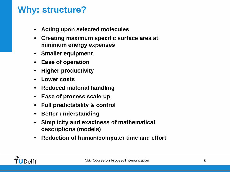
Why: structure?
• Acting upon selected molecules• Creating maximum specific surface area at
minimum energy expenses• Smaller equipment• Ease of operation• Higher productivity• Lower costs• Reduced material handling• Ease of process scale-up• Full predictability & control• Better understanding• Simplicity and exactness of mathematical
descriptions (models)• Reduction of human/computer time and effort
6MSc Course on Process Intensification
MOLECULAR SCALE

7MSc Course on Process Intensification
Methods for controlling molecular alignment and orientation
Orientation control via nano-structural confinement
Alignment and orientation control via external fields
Imprinted catalysts
Shape-selective catalysts
Liquid crystals
Molecular reactors (cyclodextrins)
Stark’s effect methods (electric field)
Molecular beam
Non-resonant laser
Brute force methodsMagnetic
Electric
Femtosecond
Adiabatic
Control of spatial orientation of molecules and geometry of collisions
• Molecules get immobilized
• Structures confining the access
• “Take it or leave it”
• Molecules move
8MSc Course on Process Intensification
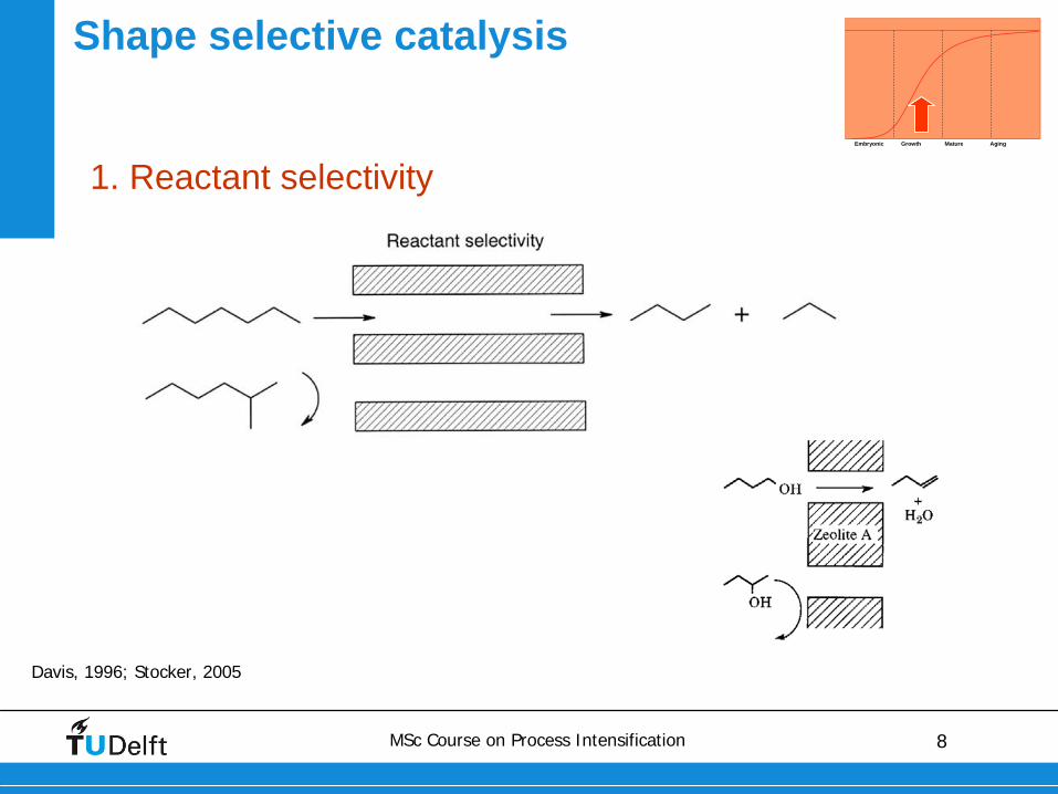
Shape selective catalysis
Davis, 1996; Stocker, 2005
1. Reactant selectivityEmbryonic Growth Mature Aging
9MSc Course on Process Intensification
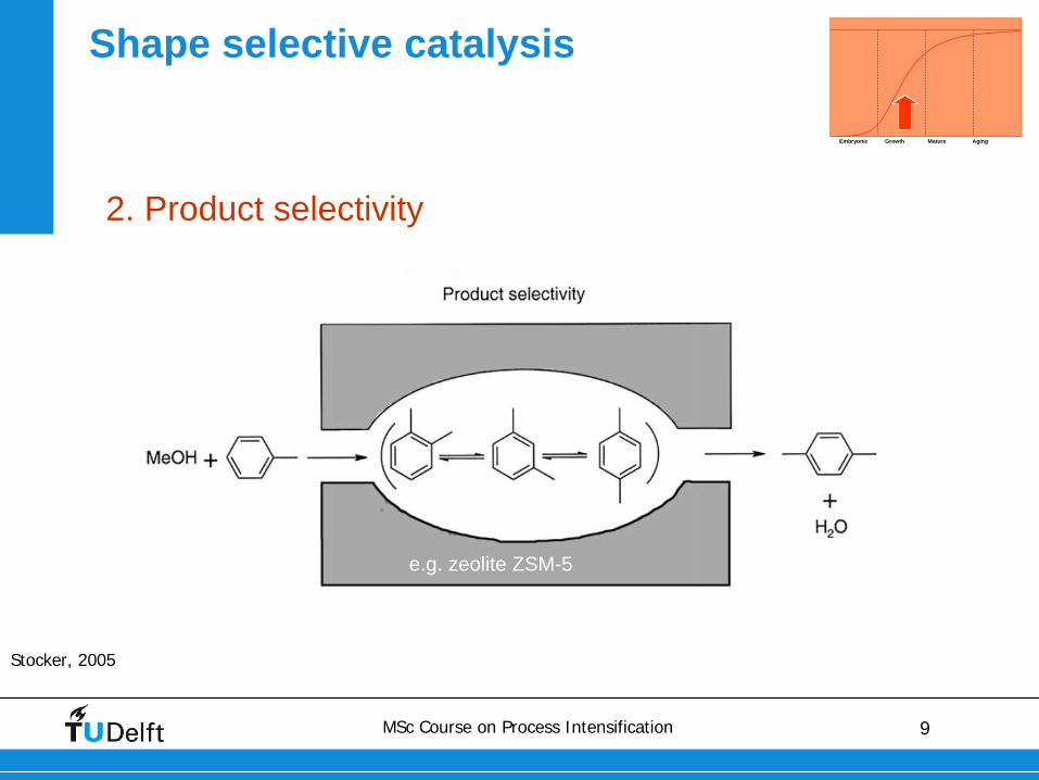
Shape selective catalysis
Stocker, 2005
2. Product selectivity
Embryonic Growth Mature Aging
e.g. zeolite ZSM-5
10MSc Course on Process Intensification
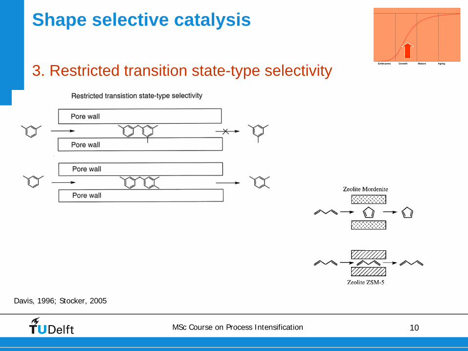
Shape selective catalysis
Davis, 1996; Stocker, 2005
3. Restricted transition state-type selectivityEmbryonic Growth Mature Aging
11MSc Course on Process Intensification
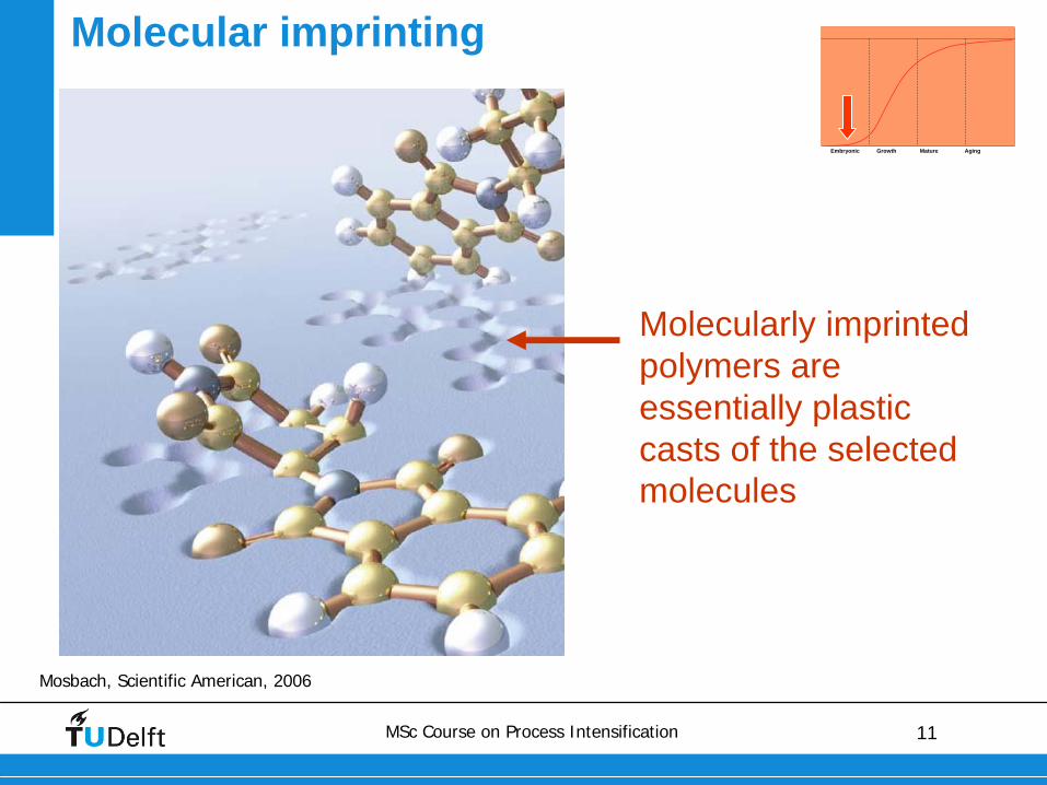
Molecular imprinting
Mosbach, Scientific American, 2006
Embryonic Growth Mature Aging
Molecularly imprinted polymers are essentially plastic casts of the selected molecules
12MSc Course on Process Intensification
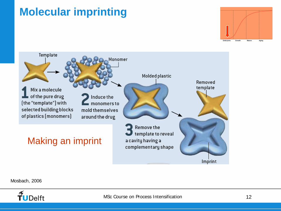
Molecular imprinting
Mosbach, 2006
Making an imprint
Embryonic Growth Mature Aging
13MSc Course on Process Intensification
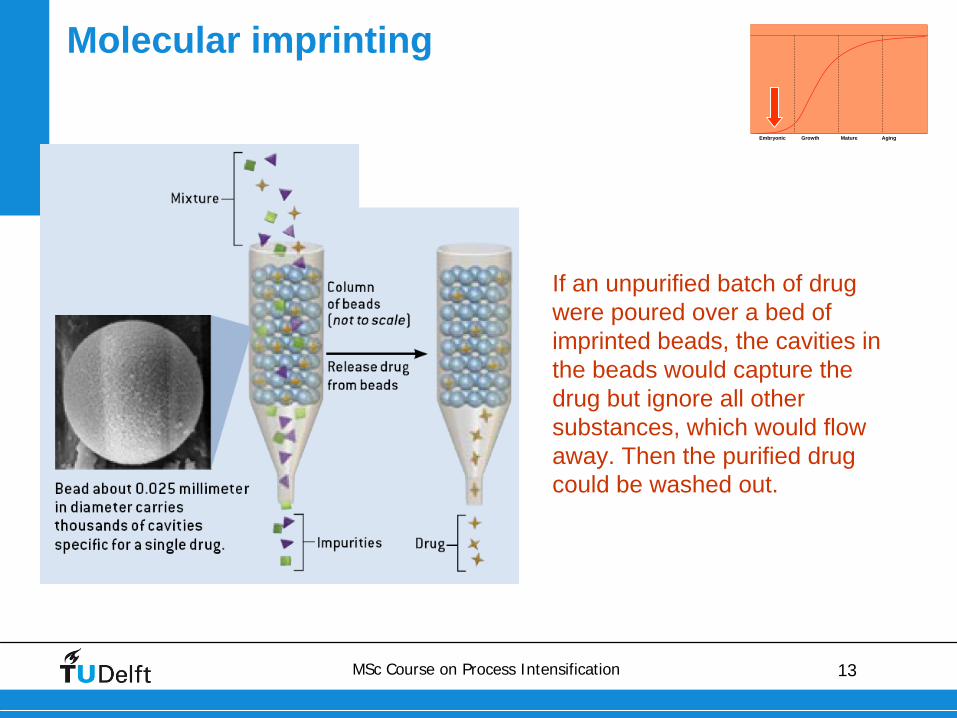
Molecular imprinting
If an unpurified batch of drug were poured over a bed of imprinted beads, the cavities in the beads would capture the drug but ignore all other substances, which would flow away. Then the purified drug could be washed out.
Embryonic Growth Mature Aging
14MSc Course on Process Intensification
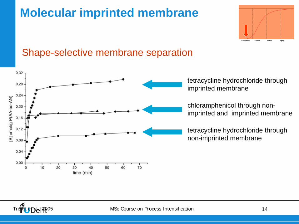
Molecular imprinted membrane
Shape-selective membrane separation
Trotta et al., 2005
tetracycline hydrochloride through non-imprinted membrane
tetracycline hydrochloride through imprinted membrane
chloramphenicol through non- imprinted and imprinted membrane
Embryonic Growth Mature Aging
15MSc Course on Process Intensification
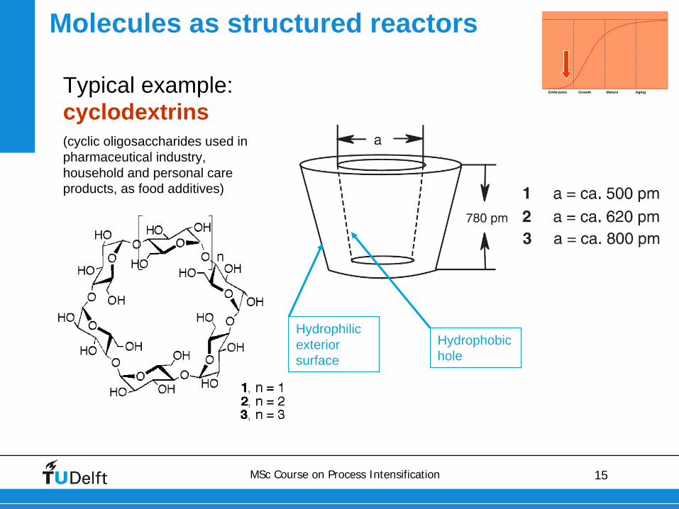
Molecules as structured reactors
Typical example: cyclodextrins(cyclic oligosaccharides used in pharmaceutical industry, household and personal care products, as food additives)
Embryonic Growth Mature Aging
Hydrophilic exterior surface
Hydrophobic hole
16MSc Course on Process Intensification
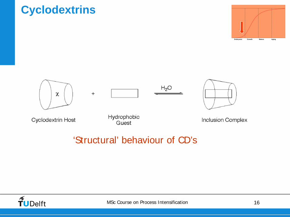
‘Structural’ behaviour of CD’s
Cyclodextrins
Embryonic Growth Mature Aging
17MSc Course on Process Intensification
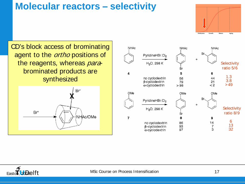
Molecular reactors –
selectivity
CD’s block access of brominating agent to the ortho positions of the reagents, whereas para-
brominated products are synthesized
Easton, 2005
Selectivity ratio 5/6
1.33.8>49
Selectivity ratio 8/9
61332
Embryonic Growth Mature Aging
18MSc Course on Process Intensification
MESO SCALE
19MSc Course on Process Intensification
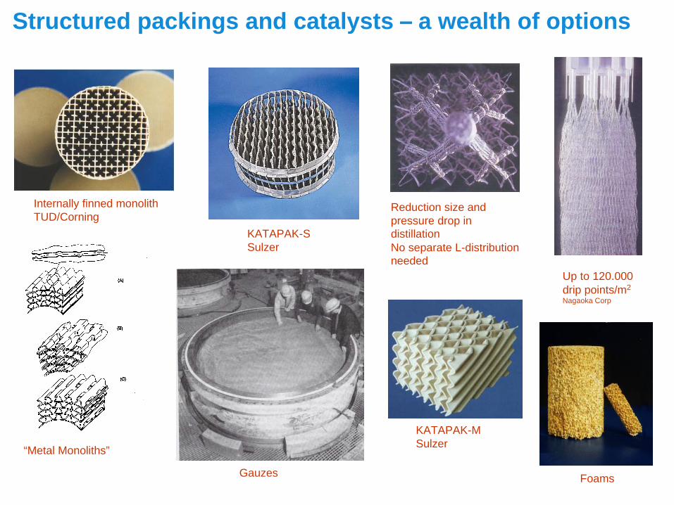
KATAPAK-SSulzer
Internally finned monolithTUD/Corning
Structured packings and catalysts –
a wealth of options
Reduction size and pressure drop in distillationNo separate L-distribution needed
“Metal Monoliths”
Up to 120.000drip points/m2
Nagaoka Corp
Gauzes
KATAPAK-MSulzer
Foams
20MSc Course on Process Intensification
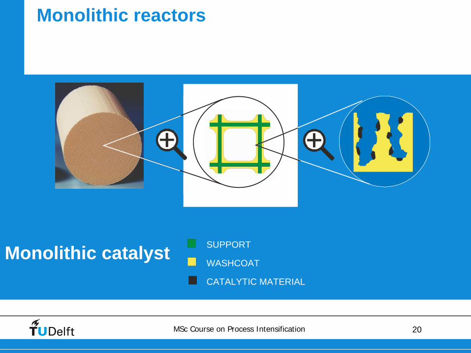
SUPPORT
WASHCOAT
CATALYTIC MATERIAL
Monolithic catalyst
Monolithic reactors
21MSc Course on Process Intensification
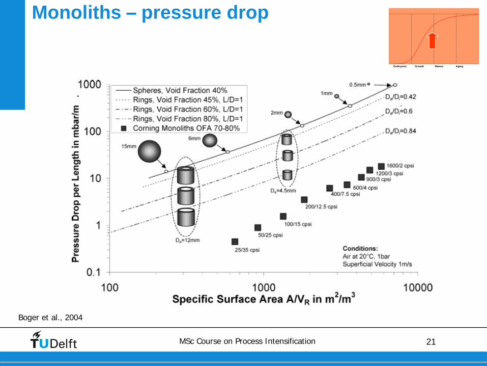
Monoliths –
pressure drop
Boger et al., 2004
Embryonic Growth Mature Aging
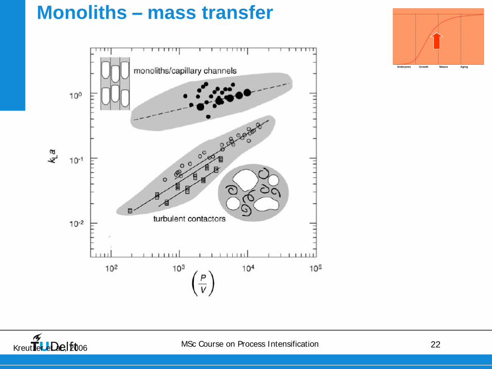
22MSc Course on Process Intensification
Monoliths –
mass transfer
Kreutzer et al., 2006
Embryonic Growth Mature Aging
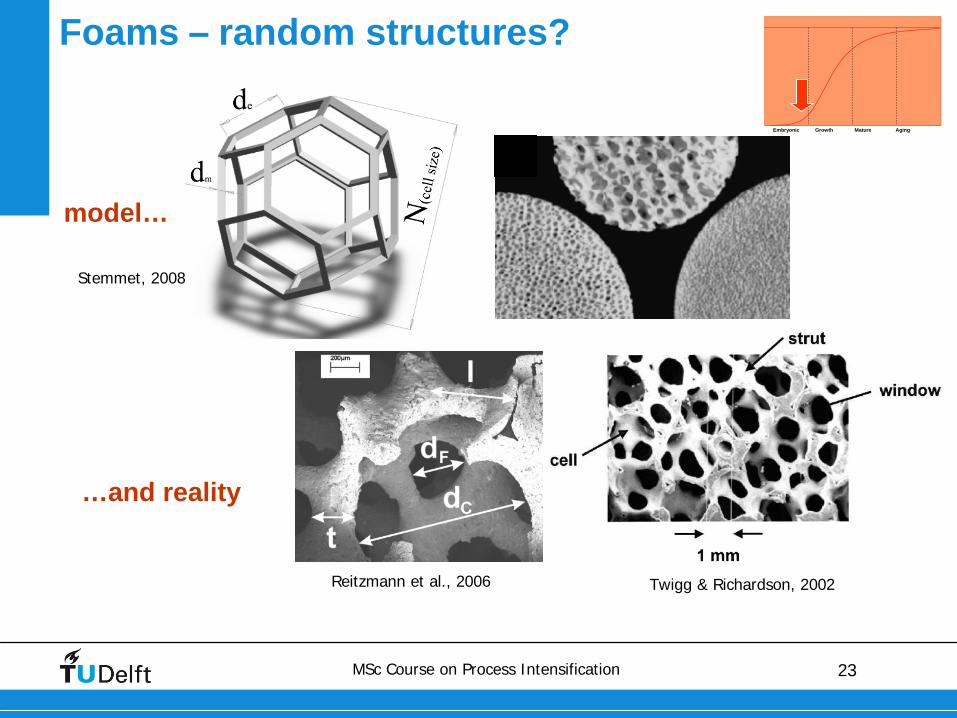
23MSc Course on Process Intensification
Foams –
random structures?
Embryonic Growth Mature Aging
Twigg & Richardson, 2002Reitzmann et al., 2006
…and reality
Stemmet, 2008
model…
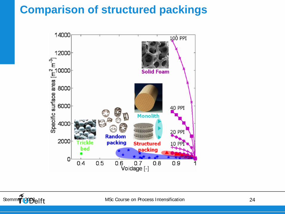
24MSc Course on Process Intensification
Comparison of structured packings
Stemmet, 2008
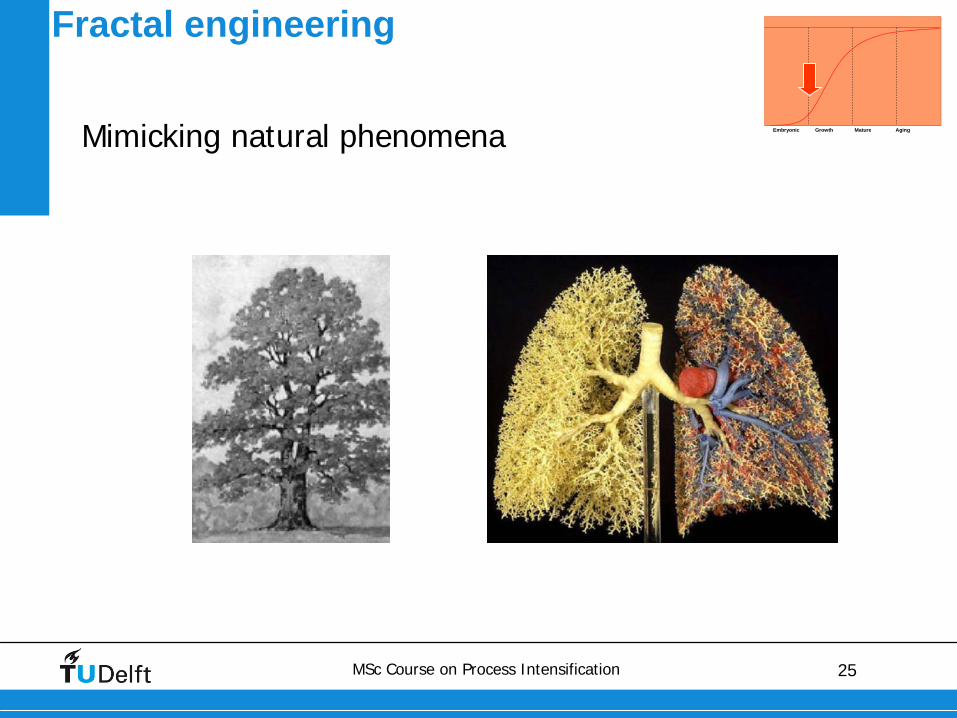
25MSc Course on Process Intensification
Fractal engineering
Mimicking natural phenomena Embryonic Growth Mature Aging
26MSc Course on Process Intensification
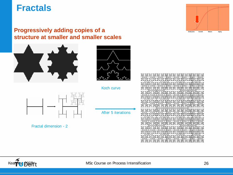
Fractals
Kearney, 2003
Embryonic Growth Mature Aging
Koch curve
Fractal dimension - 2
After 5 iterations
Progressively adding copies of a structure at smaller and smaller scales
27MSc Course on Process Intensification
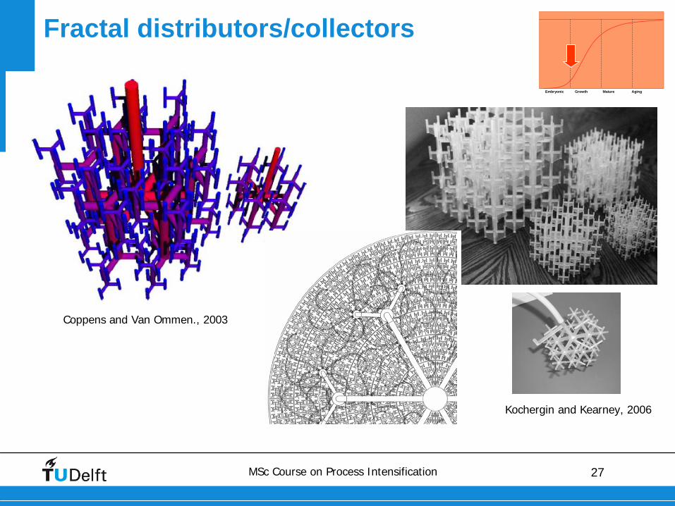
Fractal distributors/collectors
Coppens and Van Ommen., 2003
Kochergin and Kearney, 2006
Embryonic Growth Mature Aging
28MSc Course on Process Intensification
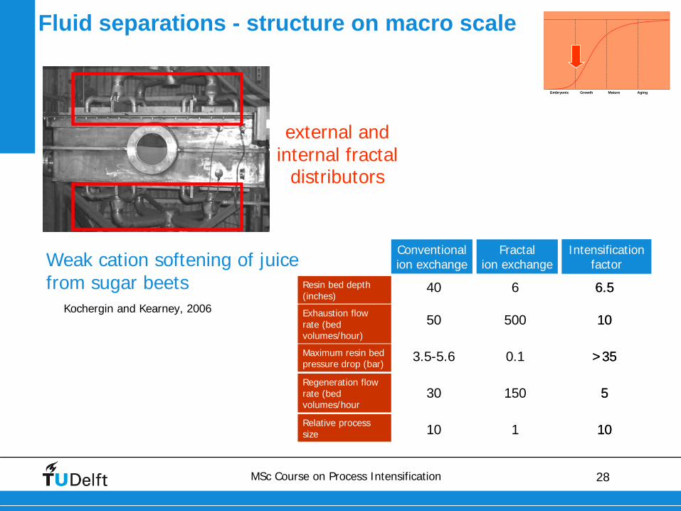
Kochergin and Kearney, 2006
external and internal fractal
distributors
Weak cation softening of juice from sugar beets
Fluid separations - structure on macro scale
Embryonic Growth Mature Aging
Conventionalion exchange
Fractal ion exchange
Resin bed depth(inches)
Exhaustion flow rate (bedvolumes/hour)
Maximum resin bedpressure drop (bar)
Regeneration flow rate (bedvolumes/hour
40 6
50 500
3.5-5.6
30 150
0.1
Relative processsize 10 1
Intensification factor
6.5
10
>35
5
10
Intensification factor
6.5
10
>35
5
10
29MSc Course on Process Intensification
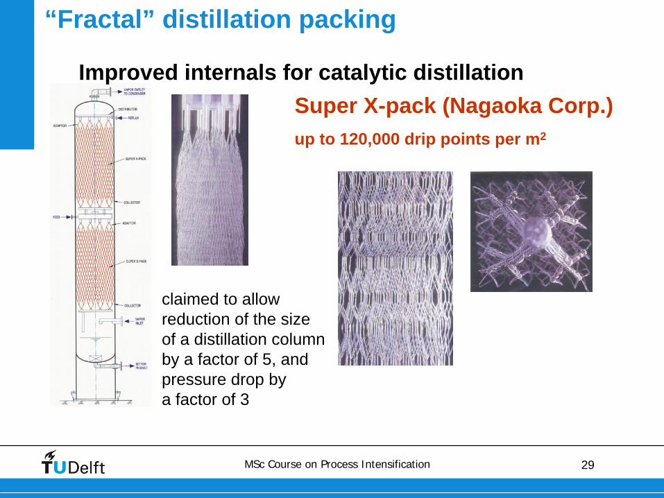
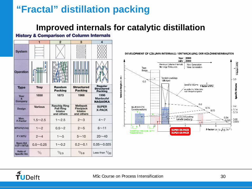
“Fractal” distillation packing
Improved internals for catalytic distillationSuper X-pack (Nagaoka Corp.)up to 120,000 drip points per m2
claimed to allowreduction of the sizeof a distillation columnby a factor of 5, andpressure drop bya factor of 3
30MSc Course on Process Intensification
Improved internals for catalytic distillation
“Fractal” distillation packing
31MSc Course on Process Intensification
MACROSCALE
32MSc Course on Process Intensification
• Structure in heat exchangers• technologies of high-intensity heat exchangers and their
applications
• Structure in mixing equipment• mixing concepts
• design of high-intensity mixers
Contents
33MSc Course on Process Intensification
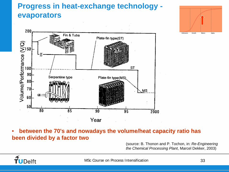
• between the 70's and nowadays the volume/heat capacity ratio has been divided by a factor two
Progress in heat-exchange technology - evaporators
(source: B. Thonon and P. Tochon, in: Re-Engineering the Chemical Processing Plant, Marcel Dekker, 2003)
Embryonic Growth Mature Aging
34MSc Course on Process Intensification
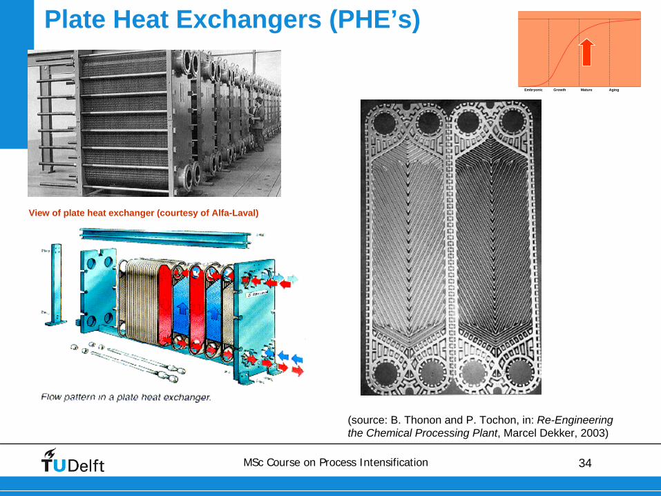
View of plate heat exchanger (courtesy of Alfa-Laval)
Plate Heat Exchangers (PHE’s)
(source: B. Thonon and P. Tochon, in: Re-Engineering the Chemical Processing Plant, Marcel Dekker, 2003)
Embryonic Growth Mature Aging
35MSc Course on Process Intensification
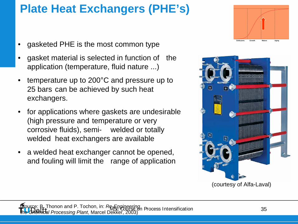
Plate Heat Exchangers (PHE’s)
(source: B. Thonon and P. Tochon, in: Re-Engineering the Chemical Processing Plant, Marcel Dekker, 2003)
• gasketed PHE is the most common type
• gasket material is selected in function of the application (temperature, fluid nature ...)
• temperature up to 200°C and pressure up to 25 bars can be achieved by such heat exchangers.
• for applications where gaskets are undesirable (high pressure and temperature or very corrosive fluids), semi- welded or totally welded heat exchangers are available
• a welded heat exchanger cannot be opened, and fouling will limit the range of application
Embryonic Growth Mature Aging
(courtesy of Alfa-Laval)
36MSc Course on Process Intensification
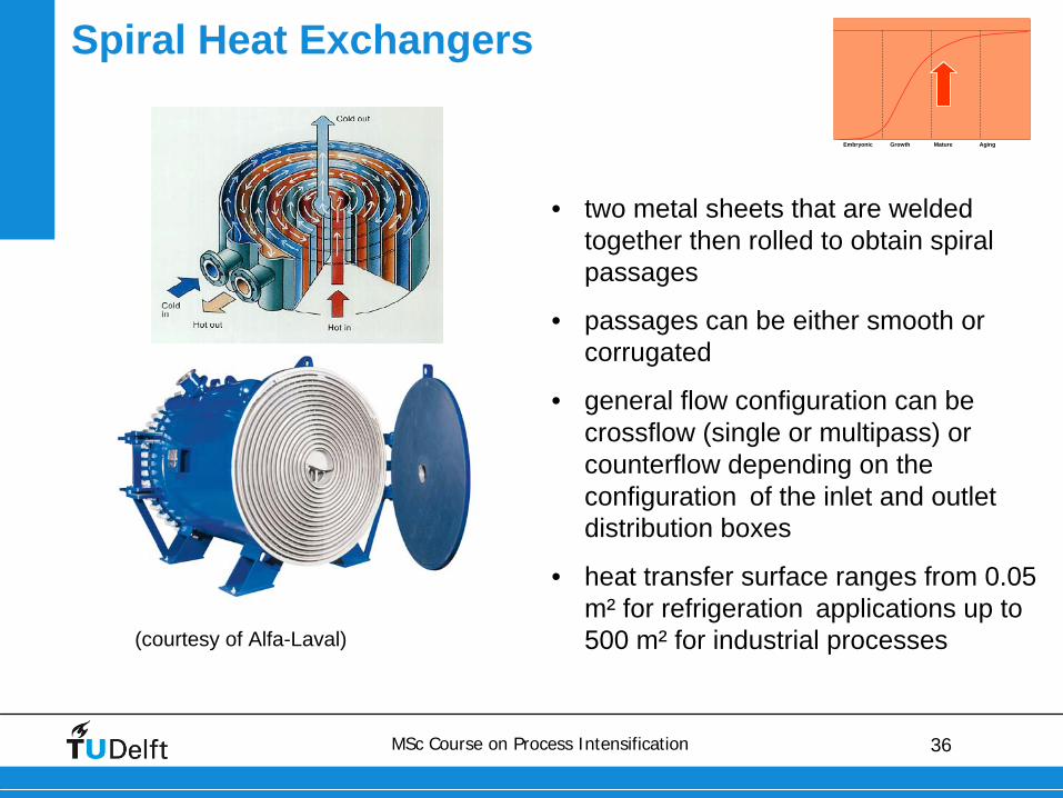
Spiral Heat Exchangers
• two metal sheets that are welded together then rolled to obtain spiral passages
• passages can be either smooth or corrugated
• general flow configuration can be crossflow (single or multipass) or counterflow depending on the configuration of the inlet and outlet distribution boxes
• heat transfer surface ranges from 0.05 m² for refrigeration applications up to 500 m² for industrial processes (courtesy of Alfa-Laval)
Embryonic Growth Mature Aging
37MSc Course on Process Intensification
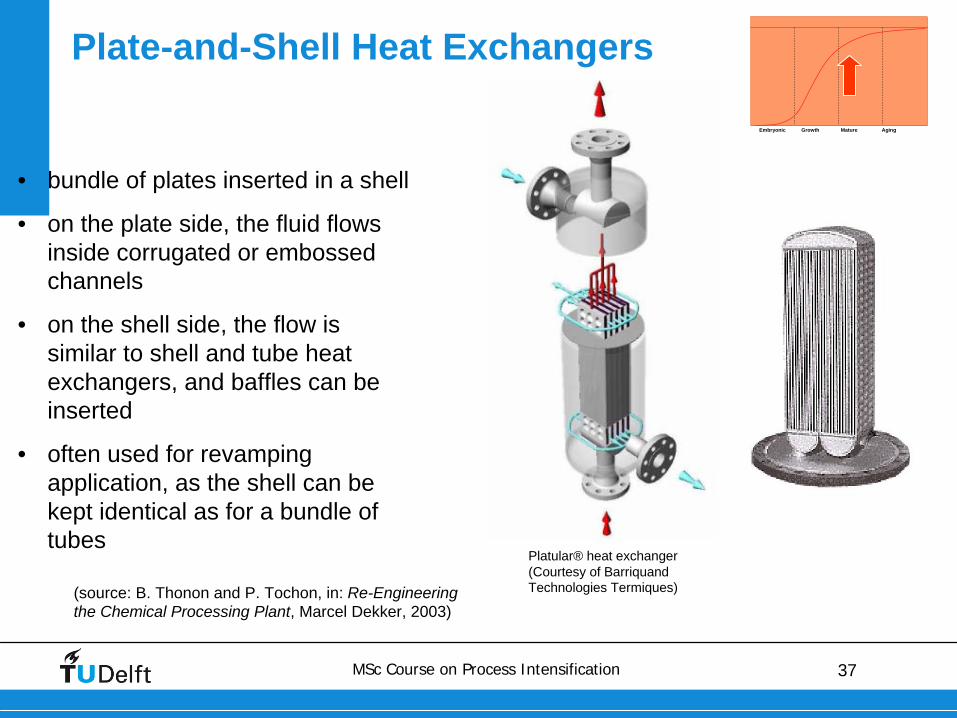
Plate-and-Shell Heat Exchangers
(source: B. Thonon and P. Tochon, in: Re-Engineering the Chemical Processing Plant, Marcel Dekker, 2003)
• bundle of plates inserted in a shell
• on the plate side, the fluid flows inside corrugated or embossed channels
• on the shell side, the flow is similar to shell and tube heat exchangers, and baffles can be inserted
• often used for revamping application, as the shell can be kept identical as for a bundle of tubes
Embryonic Growth Mature Aging
Platular® heat exchanger (Courtesy of Barriquand Technologies Termiques)
38MSc Course on Process Intensification
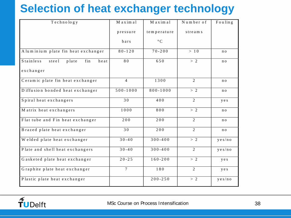
T e c h n o lo g y M a x im a l
p r e s s u r e
b a r s
M a x im a l
t e m p e r a t u r e
°C
N u m b e r o f
s t r e a m s
F o u lin g
A lu m in iu m p la t e f in h e a t e x c h a n g e r 8 0 - 1 2 0 7 0 - 2 0 0 > 1 0 n o
S t a in le s s s t e e l p la t e f in h e a t
e x c h a n g e r
8 0 6 5 0 > 2 n o
C e r a m ic p la t e f in h e a t e x c h a n g e r 4 1 3 0 0 2 n o
D iffu s io n b o n d e d h e a t e x c h a n g e r 5 0 0 - 1 0 0 0 8 0 0 - 1 0 0 0 > 2 n o
S p ir a l h e a t e x c h a n g e r s 3 0 4 0 0 2 y e s
M a t r ix h e a t e x c h a n g e r s 1 0 0 0 8 0 0 > 2 n o
F la t t u b e a n d F in h e a t e x c h a n g e r 2 0 0 2 0 0 2 n o
B r a z e d p la t e h e a t e x c h a n g e r 3 0 2 0 0 2 n o
W e ld e d p la t e h e a t e x c h a n g e r 3 0 - 4 0 3 0 0 - 4 0 0 > 2 y e s / n o
P la t e a n d s h e l l h e a t e x c h a n g e r s 3 0 - 4 0 3 0 0 - 4 0 0 2 y e s / n o
G a s k e t e d p la t e h e a t e x c h a n g e r 2 0 - 2 5 1 6 0 - 2 0 0 > 2 y e s
G r a p h it e p la t e h e a t e x c h a n g e r 7 1 8 0 2 y e s
P la s t ic p la t e h e a t e x c h a n g e r 2 0 0 - 2 5 0 > 2 y e s / n o
Selection of heat exchanger technology
39MSc Course on Process Intensification
• Structure in heat exchangers• technologies of high-intensity heat exchangers and their
applications
• Structure in mixing equipment• mixing concepts
• design of high-intensity mixers
• Microreactors
Contents
40MSc Course on Process Intensification
Why is mixing important
(source: A. Green, in: Re-Engineering the Chemical Processing Plant, Marcel Dekker, 2003)
• usually not a problem in a chemist’s beaker, where mixing can be very rapid
• if it scaled up into a batch stirred vessel, mixing inevitably becomes slower
• if mixing time is slower than the reaction time, the reaction will be artificially slowed down - it becomes mixing, rather than kinetic, limited
• in a typical process
A + B →
R
R + B →
S
if the second reaction is much slower than the first, there should not be too much S formed; however if mixing is slow, the first reaction can be artificially slowed down, which will then tend to favour production of S – and yield of R will reduce
41MSc Course on Process Intensification
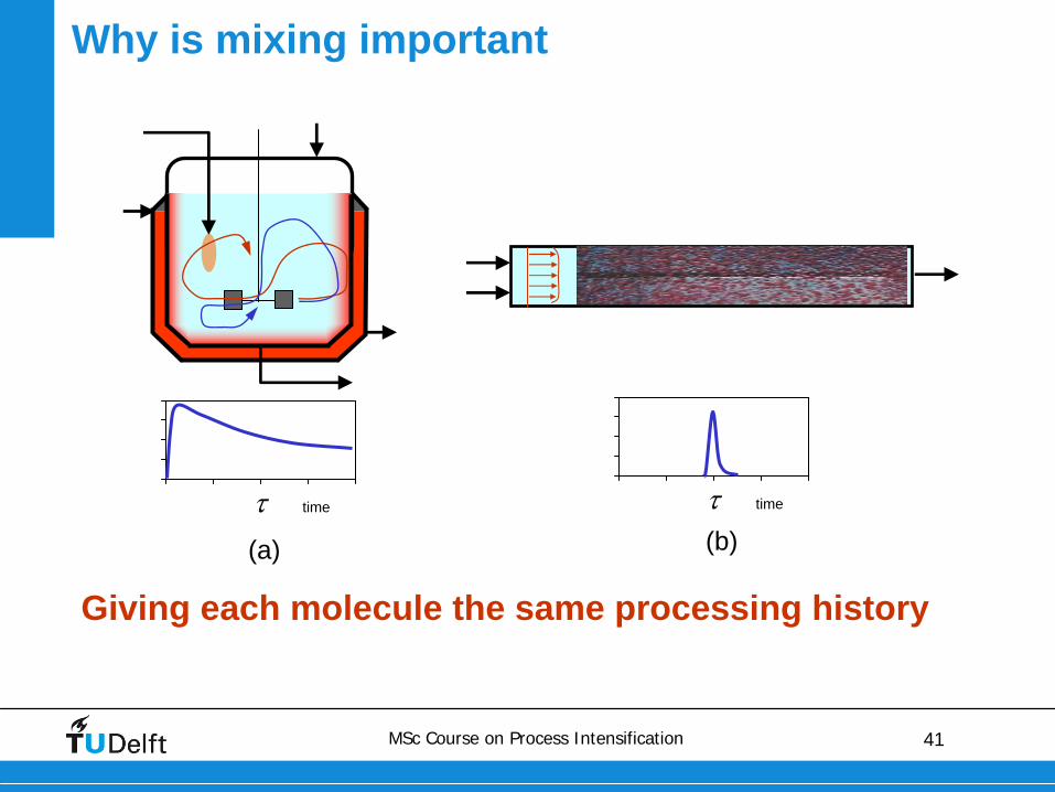
Giving each molecule the same processing history
timetime(a) (b)
Why is mixing important
42MSc Course on Process Intensification
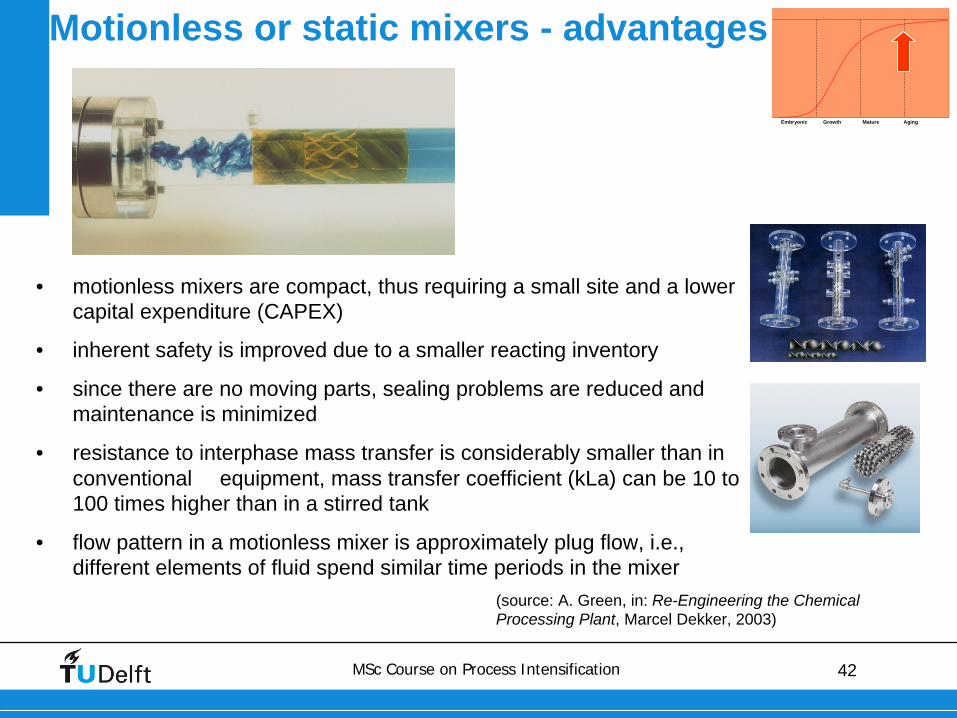
Motionless or static mixers - advantages
(source: A. Green, in: Re-Engineering the Chemical Processing Plant, Marcel Dekker, 2003)
• motionless mixers are compact, thus requiring a small site and a lower capital expenditure (CAPEX)
• inherent safety is improved due to a smaller reacting inventory
• since there are no moving parts, sealing problems are reduced and maintenance is minimized
• resistance to interphase mass transfer is considerably smaller than in conventional equipment, mass transfer coefficient (kLa) can be 10 to 100 times higher than in a stirred tank
• flow pattern in a motionless mixer is approximately plug flow, i.e., different elements of fluid spend similar time periods in the mixer
Embryonic Growth Mature Aging
43MSc Course on Process Intensification
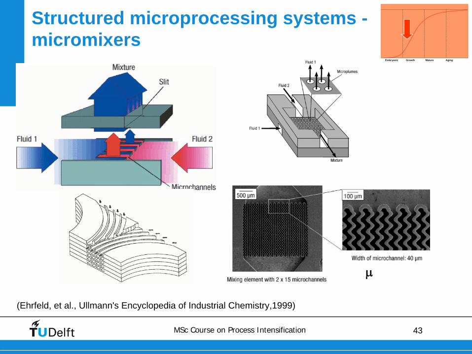
(Ehrfeld, et al., Ullmann's Encyclopedia of Industrial Chemistry,1999)
Structured microprocessing systems - micromixers
Embryonic Growth Mature Aging
44MSc Course on Process Intensification
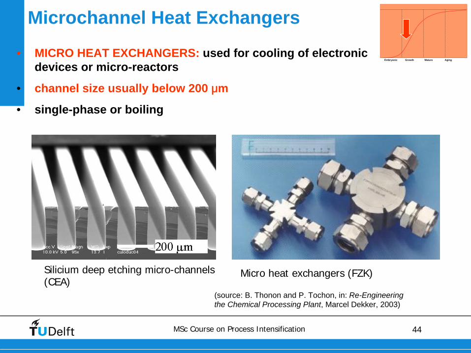
Silicium deep etching micro-channels (CEA)
Micro heat exchangers (FZK)
Microchannel Heat Exchangers
(source: B. Thonon and P. Tochon, in: Re-Engineering the Chemical Processing Plant, Marcel Dekker, 2003)
• MICRO HEAT EXCHANGERS: used for cooling of electronic devices or micro-reactors
• channel size usually below 200 μm
• single-phase or boiling
Embryonic Growth Mature Aging
45MSc Course on Process Intensification
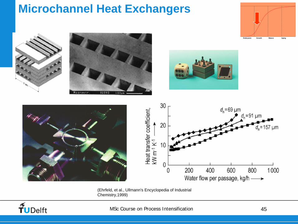
Microchannel Heat Exchangers
(Ehrfeld, et al., Ullmann's Encyclopedia of Industrial Chemistry,1999)
Embryonic Growth Mature Aging
46MSc Course on Process Intensification
15 November 2012 46
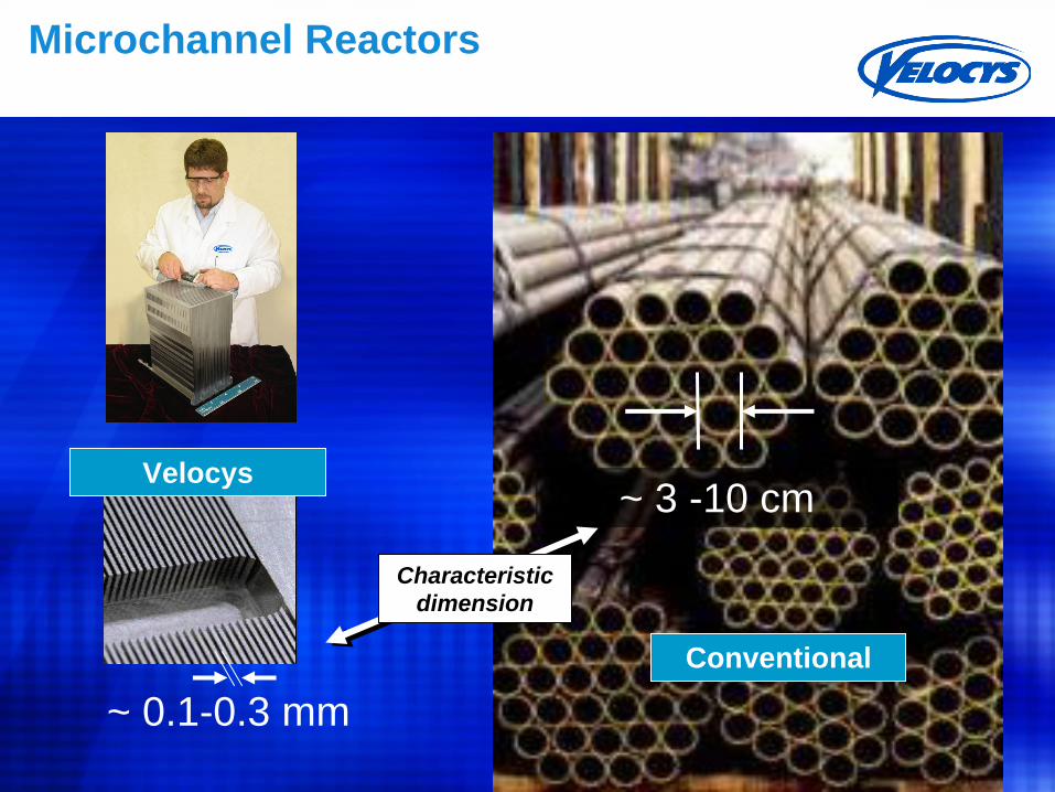
~ 0.1-0.3 mm
~ 3 -10 cm
Conventional
Characteristic dimension
Microchannel Reactors
Velocys
47MSc Course on Process Intensification
15 November 2012 47
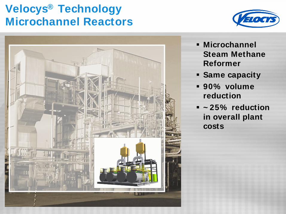
Velocys® Technology Microchannel Reactors
Microchannel Steam Methane Reformer
Same capacity
90% volume reduction
~25% reduction in overall plant costs
48MSc Course on Process Intensification
Structure versus randomness: an industrial example
49MSc Course on Process Intensification
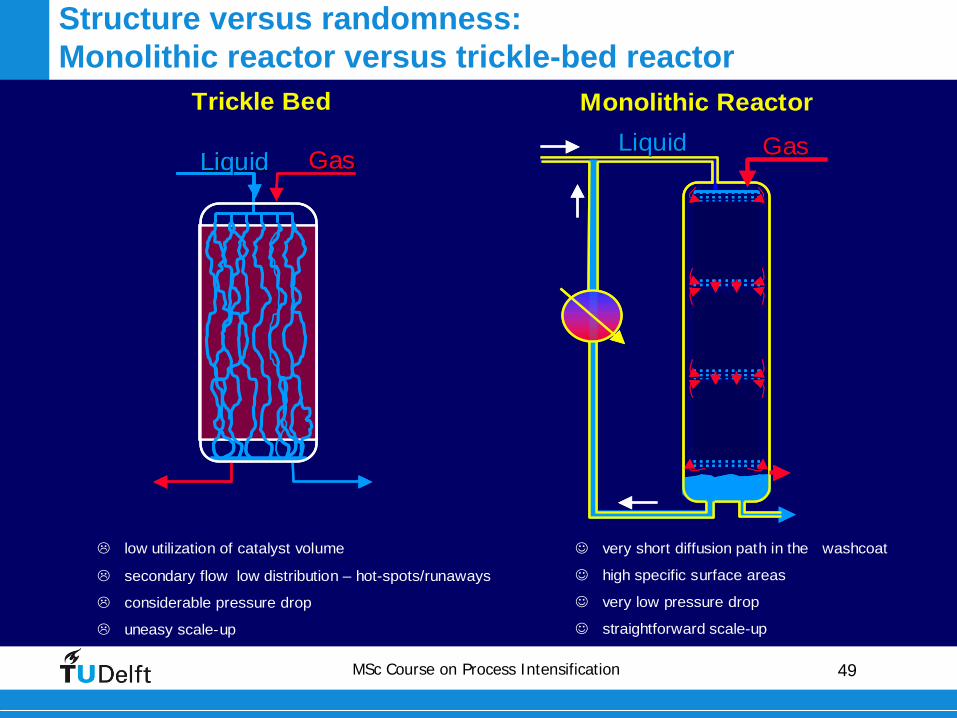
Monolithic ReactorTrickle Bed
LiquidLiquid GasGasLiquidLiquid GasGas
low utilization of catalyst volume
secondary flow low distribution – hot-spots/runaways
considerable pressure drop
uneasy scale-up
very short diffusion path in the washcoat
high specific surface areas
very low pressure drop
straightforward scale-up
LiquidLiquid GasGas
Structure versus randomness:Monolithic reactor versus trickle-bed reactor
50MSc Course on Process Intensification
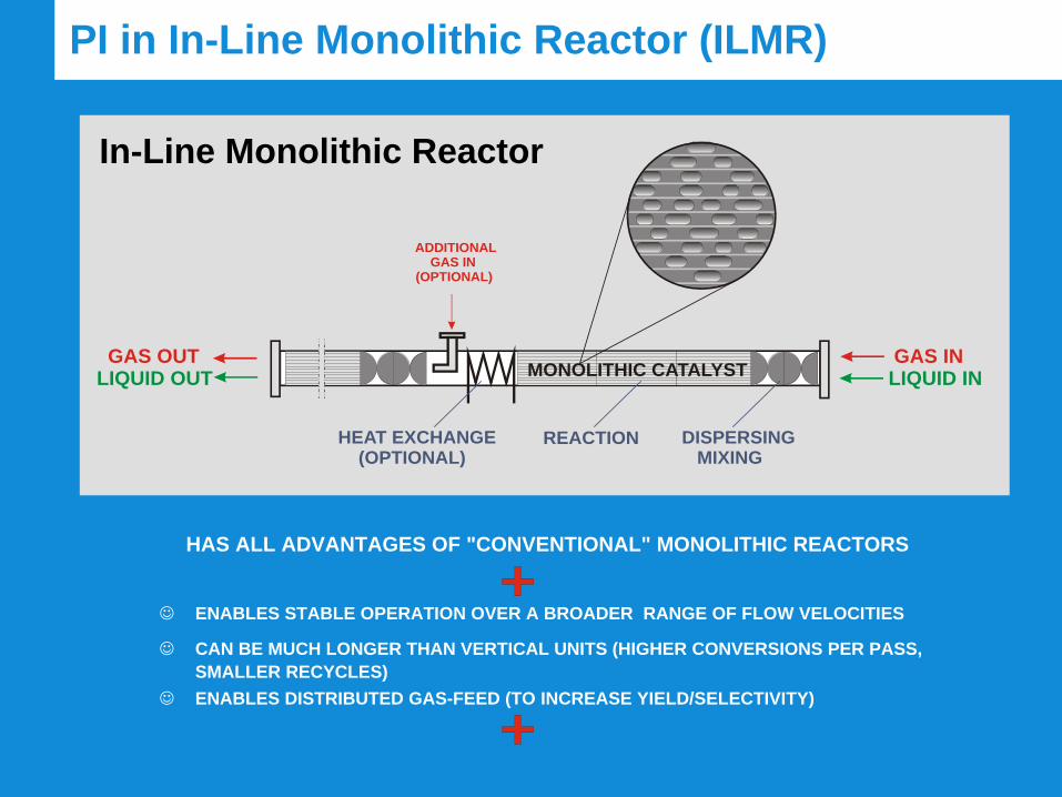
HAS ALL ADVANTAGES OF "CONVENTIONAL" MONOLITHIC REACTORS
ENABLES STABLE OPERATION OVER A BROADER RANGE OF FLOW VELOCITIES
CAN BE MUCH LONGER THAN VERTICAL UNITS (HIGHER CONVERSIONS PER PASS, SMALLER RECYCLES)
ENABLES DISTRIBUTED GAS-FEED (TO INCREASE YIELD/SELECTIVITY)
GAS OUTLIQUID OUT
GAS INLIQUID IN
ADDITIONAL GAS IN (OPTIONAL)
DISPERSING MIXING
REACTIONHEAT EXCHANGE (OPTIONAL)
MONOLITHIC CATALYST
In-Line Monolithic Reactor
PI in In-Line Monolithic Reactor (ILMR)
51MSc Course on Process Intensification
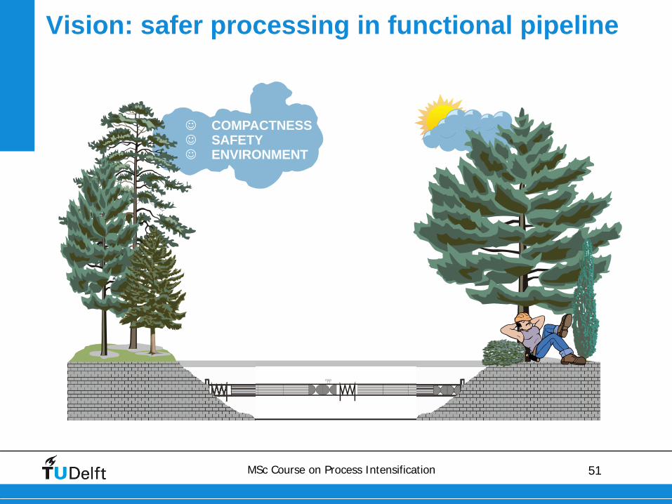
COMPACTNESSSAFETYENVIRONMENT
Vision: safer processing in functional pipeline
52MSc Course on Process Intensification
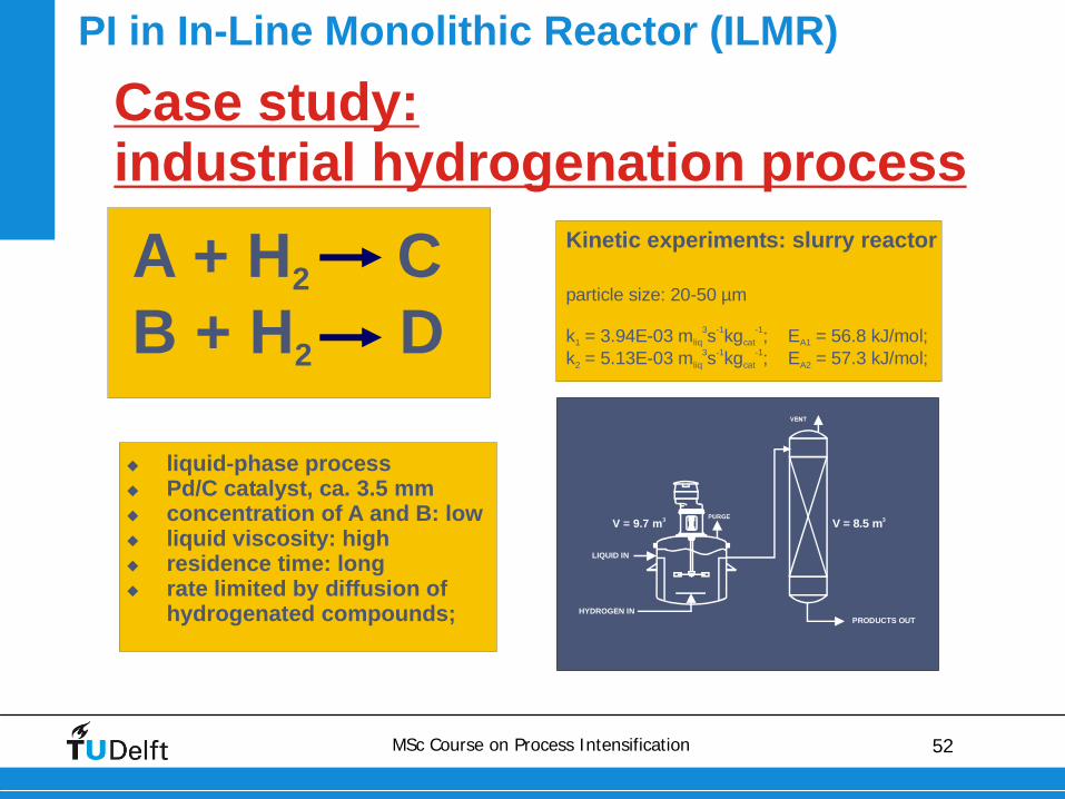
PI in In-Line Monolithic Reactor (ILMR)
LIQUID IN
HYDROGEN INPRODUCTS OUT
V = 9.7 m3 V = 8.5 m3
Case study: industrial hydrogenation process
A + H CB + H D
2
2
liquid-phase processPd/C catalyst, ca. 3.5 mmconcentration of A and B: lowliquid viscosity: highresidence time: longrate limited by diffusion of hydrogenated compounds;
Kinetic experiments: slurry reactor
particle size: 20-50 µm
k = 3.94E-03 m s kg ; E = 56.8 kJ/mol; k = 5.13E-03 m s kg ; E = 57.3 kJ/mol;
1 liq cat A1
2 liq cat A2
3 -1 -1
3 -1 -1
53MSc Course on Process Intensification
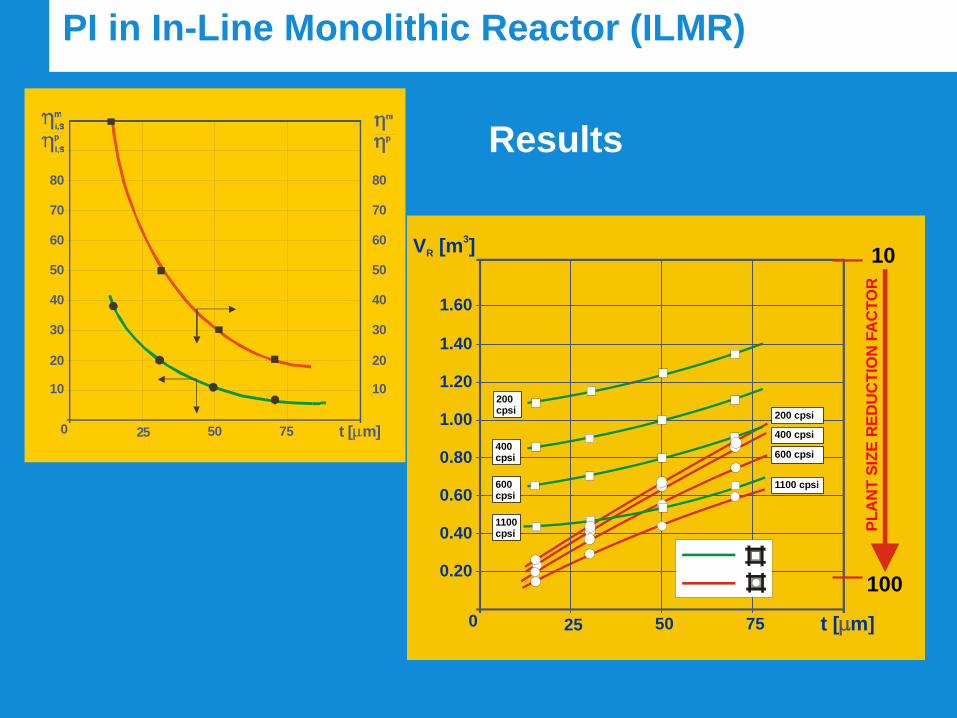
PI in In-Line Monolithic Reactor (ILMR)
0 25 50 75 t [ m]
V [m ]R3
0.20100
0.40
0.60
0.80
1.00
1.20
1.40
1.60
10
1100cpsi
600cpsi
400cpsi
200cpsi 200 cpsi
400 cpsi
600 cpsi
1100 cpsi
PLA
NT
SIZE
RED
UC
TIO
N F
AC
TOR
0 25 50 75 t [ m]
10 10
20 20
30 30
40 40
50 50
60 60
70
80
70
80
Results
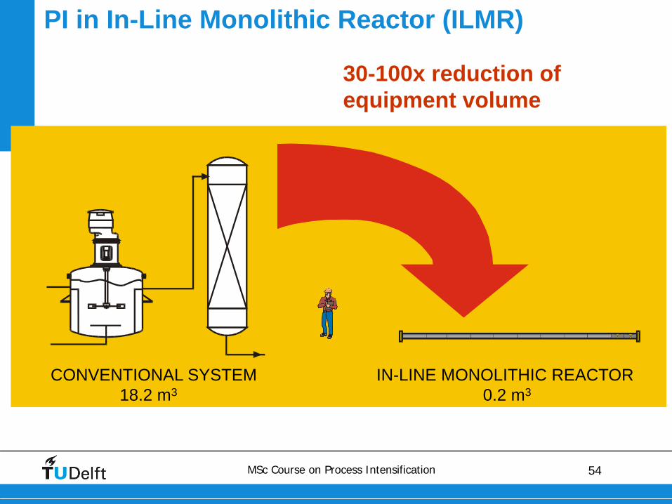
54MSc Course on Process Intensification
30-100x reduction of equipment volume
PI in In-Line Monolithic Reactor (ILMR)
CONVENTIONAL SYSTEM IN-LINE MONOLITHIC REACTOR18.2 m3 0.2 m3