process monitoring and troubleshooting
TRANSCRIPT
5 PROCESS MONITORING AND TROUBLESHOOTING
lor,
s,t
ing
ise
l-
y
elot
seed
dek,
rk.ol
g
to
rer
rdofce-ch
To produce high-quality color negatives consistently, youneed to match your process to a standard for density, coand contrast each time you process film. In addition tomonitoring process parameters such as solution times,temperature, replenishment rates, solution concentrationetc., you should regularly run control strips to ensure besresults.
This section describes standards and methods for settup your process and for ongoing process monitoring. Theprimary tools for monitoring your process are KODAKControl Strips, Process C-41, and the reference strip. Thsection describes how to use these strips and interpret thresults.
Using KODAK FLEXICOLOR Chemicals
PROCESS-MONITORING TERMSThe following terms are frequently used in processmonitoring.
Action Limits —The action limits are the boundaries of theaim operating range of the process. As long as the controstrip density values remain between the upper and loweraction limits, your process is operating correctly. If a densitvalue exceeds the action limit, it is an “early warning.” Youcan still process customer work, but you should check for thcause of the shift and correct it. When the density values pbetween the upper and lower action limits (within the “aimzone”), your process is in control.
Aim Values —You compare your control-strip densityreadings to these values. To obtain aim values, read thereference-strip densities; then apply the correction factor(supplied with the control strips and reference strip) to thosdensity readings. Enter the aim values in the spaces providon the left side of your control chart.
Color-Balance Spread Limits —A color spread is thedensity difference between the two most widely separatedensities of the HD – LD plot. If your process exceeds thcolor-balance spread limit, stop processing customer worand take corrective action.
Control Limits —The control limits define the maximumtolerances that are acceptable for processing customer woIf any density value of your process plots beyond the contrlimit, the process is out of control. Results will beunsatisfactory for color, density, or contrast. When anydensity value plots beyond the control limit, stop processincustomer work until you find the cause of the shift andcorrect it.
Control Strips —These are precisely exposed strips usedmonitor your process.
Correction Factors —Use these numbers to adjust thedensities of the reference strip to obtain aim values. They aprinted in the instruction sheet packaged with each box oroll of control strips.Correction factors are issued for eachcode number.
Reference Strip —This is a control strip that has beenprecisely exposed and processed by Kodak under standaconditions. A reference strip is packaged with each batchcontrol strips. To obtain aim values, measure the referenstrip densities and apply the correction factors for that batof control strips.
5-1

d
or
h
a.tepede
esse
s:
e
ll.
lyr
th
Tolerances and Limits —These are density variationspermitted before you must take corrective action. Theyinclude an aim-value adjustment tolerance, and action ancontrol limits. The tolerances and limits listed in Table 5-1apply to KODAK Control Strips, Process C-41.
Table 5-1 Tolerances and Limits forKODAK Control Strips, Process C-41
KODAK CONTROL STRIPS,PROCESS C-41Use KODAK Control Strips, Process C-41, to monitorProcesses C-41, C-41B, and C-41RA. By plotting thedensities of the different steps of the strip, you can monitthe D-min, speed (LD), and contrast (HD – LD) of yourprocess, and detect retained silver (by calculating andplotting D-maxB – YB).
MeasurementAim-Value
AdjustmentTolerance
ActionLimits
ControlLimits
Color-BalanceSpreadLimit
D-min ± 0.03 + 0.03 + 0.05 NA
LD ± 0.04 ± 0.06 ± 0.08 NA
HD – LD ± 0.03 ± 0.07 ± 0.09 0.09
D-maxB – YB ± 0.07 + 0.10 + 0.12 NA
NA = Not applicable
5-2
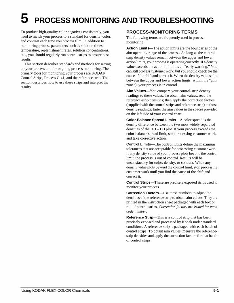
KODAK Control Strips, Process C-41 (35 mm)(CAT No. 180 3709)These 35 mm strips are supplied in 100-foot rolls ofapproximately 120 strips with cutoff notches at 91⁄2-inch(24.1 cm) intervals. A reference strip is included with eacroll. The roll is woundemulsion side in,with the D-min endsof the strips toward the outer end of the roll.
Each strip has 12 density steps: a yellow step or yellowpatch; 10 equal-increment density steps; and a D-min areThe 10 equal-increment density steps include a D-max sat the top, as well as the HD and LD steps, which are markby a “U” or notch. The D-min area is the area adjacent to thblack dot near the bottom of the strip.
KODAK Control Strips, Process C-41(CAT No. 151 9677)These 35 mm x 51⁄4-inch strips are supplied in a box of fivefoil packages that contain 10 strips each. Each box includa reference strip. The ends of the strips are perforated for uwith standard control-strip racks. Each strip has five stepD-min, LD, HD, D-max, and yellow. A raised dimple islocated on the emulsion side at the low-density end of thstrip.
KODAK Full Frame Control Strips, Process C-41(35 mm) (CAT No. 157 6701)These 35 mm strips are supplied in 100-foot rolls ofapproximately 80 strips with cutoff notches at 15-inch(38.1 cm) intervals. The roll is woundemulsion side in,withthe D-min ends of the strips toward the outer end of the roA reference strip is included with each roll.
Each strip has five full-frame density steps: D-min, LD,HD, D-max, and yellow. These strips are designed primarifor use with minilab system printers that use a film scanneas a built-in densitometer. However, you can use them wiany densitometer that can read large-area transmissiondensity.
Using KODAK FLEXICOLOR Chemicals
Figure 5-1 KODAK Control Strips, Process C-41
F002_9092EC
0065C-41
0041C-41
0073
1 D-MIN
2 LD
3 HD
4 D-MAX
DATE:
YELLOW5
C-41
Strip35 mm
Strip35 mm
5¼-Inch
StripControl
Full Frame
9½-Inch
Yellow Patch
D-Max
HD
LD
Cutoff Notch
D-Min
Yellow Patch
D-Max
HD
LD
D-Min
Cutoff Notch
Raised Dimple
F002_9092ECA
Using KODAK FLEXICOLOR Chemicals 5-3
le’s
there
t
ts
eppe
rs
in
ess
s,
rd
r
h
u
ax,
ece
h
,
nes
f
hes
se
er
Storing and Handling Control StripsStore unused control strips at –18˚C (0˚F) or lower. Handunprocessed strips in total darkness. Remove only a daysupply from one package at a time; reseal and return thepackage to the freezer as quickly as possible. Do not keeppackage out of the freezer for more than 1 hour per day. Stoyour daily supply of control strips in a lighttight container aroom temperature. At the end of the day, discard anyunprocessed strips that you removed from the freezer.
Handle control strips by the edges to prevent fingerprinand surface damage. If film sticking, static marking, ormoisture mottle occurs, allow the strips to warm up to roomtemperature before you process them.
When your shipment of control strips arrives, remove threference strip from the box before you put the control-striboxes in the freezer. Store the reference strip in its envelowhen you are not using it.
Starting OutTo begin process monitoring, you will need—• KODAK Control Strips, Process C-41
• An electronic densitometer equipped with Status M filte
• KODAK Process Record Form Y-55 or similar graphpaper
• Red, green, and blue pencils
You can also plot your process by using the procedurethe KODATEL Quality Management System.
Processing Control StripsEach time you process a control strip, position it in the samlocation in your processor. In continuous processors, procethe D-min end of the strip first; in rack-and-tank processorfasten the strip to a film clip with the D-min end up.
Process a control strip —• At the beginning of the day or shift before processing
customer work
• At regular intervals with customer work
• At the end of the day or shift
Plotting Control-Strip DensitiesCreate a control chart by using the KODAK Process RecoForm Y-55 or similar graph paper. Follow the proceduregiven below. Your chart will look like the examples shownin this section.
1. Draw in the action and control limits given inTable 5-1. Use black for the action limits and red fothe control limits.
2. Remove the reference strip from the box of controlstrips. If you removed the box from cold storage, allowthe reference strip to warm up to room temperaturebefore you remove it from its envelope (about15 minutes). Exposing a frozen strip to warm, moistair can cause low readings, particularly in thehigher-density patches.
3. Measure the Status M densities in the center of eacpatch with a precision electronic densitometer.Do not
5-4
move the strip as you make the density reading or yomay affect the precision and repeatability of themeasurements. Measure the blue density of the D-m(D-maxB) and yellow (YB) steps, and measure the redgreen, and blue densities of the LD, HD, and D-minsteps. If you have several boxes of strips with the samcode number, average the readings of all the referenstrips. A code number on the box label and thereference and control strips identifies each batch.
4. To calculate aim values, add the correction factorssupplied in the instruction sheet packaged with eacbox of control strips to the reference-strip densities.Note the sign of the correction factor. If it is negativeyou need to subtract the correction factor. If youaveraged the reference-strip readings from severalboxes of the same code number, apply the correctiofactors to the average. These corrected density valuare the aim values for that batch of control strips.Record them in the proper spaces in the left margin oForm Y-55.
• To obtain the HD – LD aim values, subtract theadjusted LD densities from the adjusted HDdensities.
• To obtain the D-maxB – YB aim value, subtractthe adjusted blue-filter density of the yellow stepfrom the adjusted blue-filter density of the D-maxstep.
5. Process a control strip and measure the same patcthat you measured in step 3.
6. Calculate the variations from aim by subtracting theaim densities from your control-strip densities. Plotthe variations on your control chart.
• Plot differences that arelarger than thecorresponding aim values (+ values)above theaim line.
• Plot differences that aresmaller than the aimvalues (– values)below the aim line.
7. If any of the variations from aim plot beyond the actionor control limits, process another control strip. If thesecond strip confirms the results, determine the cauof the problem. The diagnostic charts and control-chart examples in this section will help youtroubleshoot your process problems.
8. Whenever you take corrective action, process anothcontrol strip to confirm that the change you madereturned the process to control before you resumenormal processing. SeeControl-Chart Examples.
Using KODAK FLEXICOLOR Chemicals
sto
t
e
e
ps.
e
me
e
he
he
inal
es.enle
Changing to a New Batch of Control StripsWhen you change from your current batch of control stripto strips with a different code number, make a crossover confirm that both code numbers provide the sameinformation. The following procedure allows you to makeadjustments for minor code-to-code variations. Using thecrossover procedure in the KODATEL Quality ManagemenSystem will simplify the process.
Be sure that your process is stable and in control beforyou begin using a new batch of control strips.
1. While you still have a week’s supply of control stripsof your current code, process one control strip from thnew batch of strips with one strip from the currentbatchin three separate runs.
2. Read and record the densities of the processed stri
3. Determine aim values for the new batch of controlstrips by following steps 2 through 4 underPlottingControl-Strip Densities.
4. For your current batch of strips, calculate thevariations from aim by subtracting your current aimdensities from the densities of the three strips. Plot thvariations on your control chart.
5. For the new batch of strips, calculate the variationsfrom aim by subtracting the new aim densitiescalculated in step 3 from the densities of the threestrips. Plot the variations on your control chart.
6. Calculate the differences between the variations froaim of the current strips and the new strips. Averagthese differences, and then divide the result by 2.
7. Depending on the sign of the differences, adjust theaim values for the new batch of strips by adding orsubtracting the results from step 6. The amount of thadjustment should not exceed the aim-valueadjustment tolerances given in Table 5-1. If theadjustment is greater than the tolerance, determine tcause. Check your calculations, densitometer, andcontrol strips.
8. Record the new aim values and the code number of tnew batch of strips on your control chart, and beginusing the new strips.
Using KODAK FLEXICOLOR Chemicals
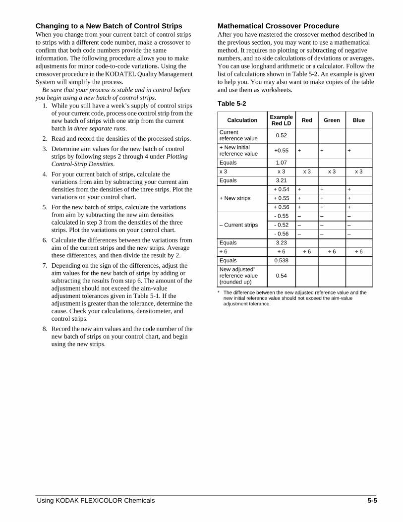
Mathematical Crossover ProcedureAfter you have mastered the crossover method describedthe previous section, you may want to use a mathematicmethod. It requires no plotting or subtracting of negativenumbers, and no side calculations of deviations or averagYou can use longhand arithmetic or a calculator. Follow thlist of calculations shown in Table 5-2. An example is giveto help you. You may also want to make copies of the taband use them as worksheets.
Table 5-2
Calculation ExampleRed LD Red Green Blue
Currentreference value 0.52
+ New initialreference value +0.55 + + +
Equals 1.07
x 3 x 3 x 3 x 3 x 3
Equals 3.21
+ New strips
+ 0.54 + + +
+ 0.55 + + +
+ 0.56 + + +
– Current strips
- 0.55 – – –
- 0.52 – – –
- 0.56 – – –
Equals 3.23
÷ 6 ÷ 6 ÷ 6 ÷ 6 ÷ 6
Equals 0.538
New adjusted*
reference value(rounded up)
* The difference between the new adjusted reference value and thenew initial reference value should not exceed the aim-valueadjustment tolerance.
0.54
5-5

.t
ss
.
ing
n.
ct
y
ts
ew
heed
at
sy
n
stlt
dartn
elt,
INTERPRETING YOUR CONTROL PLOTYour control plot provides a running record of your processIt will show how consistent your process is, and how well imeets your aim. It provides you with helpful information foranalyzing and correcting process problems. Your proceswill produce acceptable results if your control strips alwayplot within the control limits.
Corrective ActionWhen a control strip plots outside the control limits, or if theplot shows a gradual drift toward an out-of-controlcondition, immediately check for the cause and correct itFirst, determine if the process drifted out of control slowlyover time or if it occurred suddenly.
Gradual ChangeGradual changes to an out-of-control condition indicate aproblem that could be caused by the following:
Improper replenishment —Check that the replenishmentrate is correct and that the replenishment system is operatproperly. Also check for an incorrectly mixed replenisher.
Evaporation or oxidation —Check for low utilization orair drawn into the processing solutions by a bad pump, arecirculation-system leak, or a poorly placed ventilation fa
Contamination —Check for photographically activematerials that leach slowly into the solutions. Thecontaminant may come from any material that is in contawith the solutions, such as the filters, plumbing, etc.
Incorrect mixing —Check for mixing errors caused byimproper measurement, improper calibration of mixingtanks, etc. If you suspect that the problem was caused breplenisher solution that was mixed incorrectly, mix a newbatch of replenisher to see if a fresh mix gradually correcthe problem.
5-6
Sudden ChangeSudden changes to an out-of-control condition indicate aproblem that can be caused by the following:
Control strip —Check that you used a control strip from thecorrect code number. Remember, if you change codenumbers, you need to establish new aim values for the nbatch (seeChanging to a New Batch of Control Strips).Check that the control-strip code numbers match those of treference strip, and that the strips were handled and storproperly.
Densitometer —If your densitometer is not workingproperly or is out of calibration, the density readings will bewrong. This can falsely signal a process change. Check thyou used Status M filters.
Time or temperature —Check that the time andtemperature were set correctly, particularly if they are eato change.
Agitation —Check that pumps are working and that theburst distribution, duration, and interval are correct.
Contamination —Very small amounts of bleach or fixercan contaminate the developer tank or replenisher solutioand cause a large density and color shift.
Solution mixing —If the sudden change occurs after youhave mixed a fresh tank solution, check that it was mixedcorrectly.
Aim Values —Check that you compared the control-stripdensities with the correct aim values.
Note: When you troubleshoot a problem, check the easieand most obvious causes first; then check the more difficuand less likely causes.
To help determine the cause of an out-of-controlcondition, use the information underDiagnostic Chartsandthe sample plots underControl-Chart Examples. Thediagnostic charts are flowcharts that list problems and leayou through possible causes and solutions. The control-chexamples demonstrate the effects of a single condition ocontrol-strip plots. If your chart shows a similar effect, youmay be able to tell if your process is affected by the samproblem. However, sometimes a diagnosis is more difficubecause a problem may have more than one cause.
Using KODAK FLEXICOLOR Chemicals

g
ue
de,
er-ed
re,
d
t
llic
oftheor
n
ct
t.
er
n
ent
e
r
rte
as
nd
.eolts
acke
perm,irehe ait.
ef
m
Daily Processing LogUse a daily processing log for your processor. A processinlog will provide you with a convenient means of keepingtrack of the amount of film you process and can provide yowith valuable information in case of process and/or machinproblems.
How Each Processing Solution Affects YourResultsEach solution affects the emulsion differently.Understanding the reaction of each solution can help youdiagnose processing problems. See the processspecifications listed in Section 2,Continuous, Roller-Transport, and Rack-and-Tank Processors; Section 3,Sink-Line, Batch, and Rotary-Tube Processors; and Section 4,Minilab Processors.
DeveloperThe developer chemically reduces the exposed silver haliin the film to form a metallic silver image. At the same timethe color developing agent in the developer oxidizes andcombines with color couplers at the site of the silver imagin each of the dye-forming emulsion layers to form a colodye image. Once the dye image has formed, there is no nefor the silver image. It is removed later by bleaching andfixing.
The amount of cyan, magenta, and yellow dye formeddepends on exposure and developer activity. Temperatutime, replenishment rate, replenisher concentration,agitation, and the rate at which solutions diffuse into theemulsion affect developer activity. Time, temperature, anagitation affect the diffusion rate. Withtoo much developeractivity, too much dye forms and the density values will plohigher than normal. Withtoo little activity, not enough dyeforms and the density values will plot lower than normal.
BleachThe bleach stops the developer activity and converts metasilver back to silver halide. The silver halide is laterdissolved in the fixer.
Bleach concentration and the rate at which the solutiondiffuses into the emulsion affect bleach activity. Time,agitation, and temperature affect the rate of diffusion.Replenishment rate, mixing procedures, and aerationefficiency affect the chemical concentrations. Bleachaeration adds oxygen needed to convert the reducedbleaching agent to an active form.
If bleaching is inadequate, less than the normal amountcyan dye is formed because some of the dye remains in leuco (colorless) condition. This adversely affects the colbalance. Bleach time that is too short, bleach that is toodilute, or insufficient bleach aeration can cause leuco-cyadye to form.
Inadequate bleaching can also cause retained silverbecause not all the metallic silver is converted to silverhalide. Leuco-cyan dye and retained silver adversely affeimage quality, but you can correct both conditions byrebleaching and refixing the film in good solutions.
Using KODAK FLEXICOLOR Chemicals
Bleach Aeration —In Process C-41, you must aerate thebleach to convert iron II back to iron III, the bleaching agenIf the concentration of iron II is not kept near zero, leuco-cyan dye is likely to form.
FixerThe fixer converts silver halide in the film into soluble silvercomplexes that are washed from the film. You can recovthe silver with electrolytic silver-recovery units and/orchemical-recovery cartridges. Fixing efficiency depends ofixer activity and the diffusion rate into the emulsion.Temperature, replenisher concentration, and replenishmrate affect fixer activity. Time and agitation affect thediffusion rate.
Inadequate fixing may not remove all of the sensitizingdyes and silver halide. An increase in the red and greenD-min densities of the control plot is one sign of incompletfixing. Another sign is a milky appearance in the D-minareas of control strips and processed film. If this problemoccurs, you can test the fixer by refixing the control strip (ofilm) in a fixer that you are sure is good. If refixing the stripcorrects the control plot, the original fixer is probablyexhausted. You can correct inadequately fixed film byrefixing it.
The most probable causes of inadequate fixing are fixethat is diluted by excessive solution carryover, an inadequafixing time, underreplenishment, a replenisher that isunderconcentrated, and fixer sulfurization. Temperature hvery little effect on the fixing rate if other fixer conditionsare within tolerances. Agitation is necessary for uniformfixing.
WashWashing removes residual chemicals from the film. If thechemicals are not removed, they can degrade the image acause the dyes to fade. Good washing requires enoughcirculation to keep fresh water in contact with the emulsionThe water temperature must be warm enough to swell thgelatin so that the water moves freely into the emulsion tremove the chemicals, but not so warm that the gelatin meor is permanently distorted.
For rack-and-tank processors, be sure that the entire ris washed; if bleach or fixer is trapped on hanger clips, thsolution can run down onto the film. Also, if the solutiondries on the hangers, it can be carried back into the develoand can cause severe contamination. To avoid this problekeep the level of the final wash high enough so that the entrack is immersed during washing or you can spray-wash track just before it enters the dryer. If your processor usesleader film, be sure to wash it thoroughly before you reuse
Stabilizer/Final RinseThe stabilizer or final rinse has no sensitometric effect on thfilm, but has the greatest impact on the physical quality oprocessed film. If the stabilizer or final rinse isunderreplenished, or if it contains particulate material froa “dirty” water supply or biological growth, it can leavedrying marks and deposits on processed film.
5-7

p
sfer
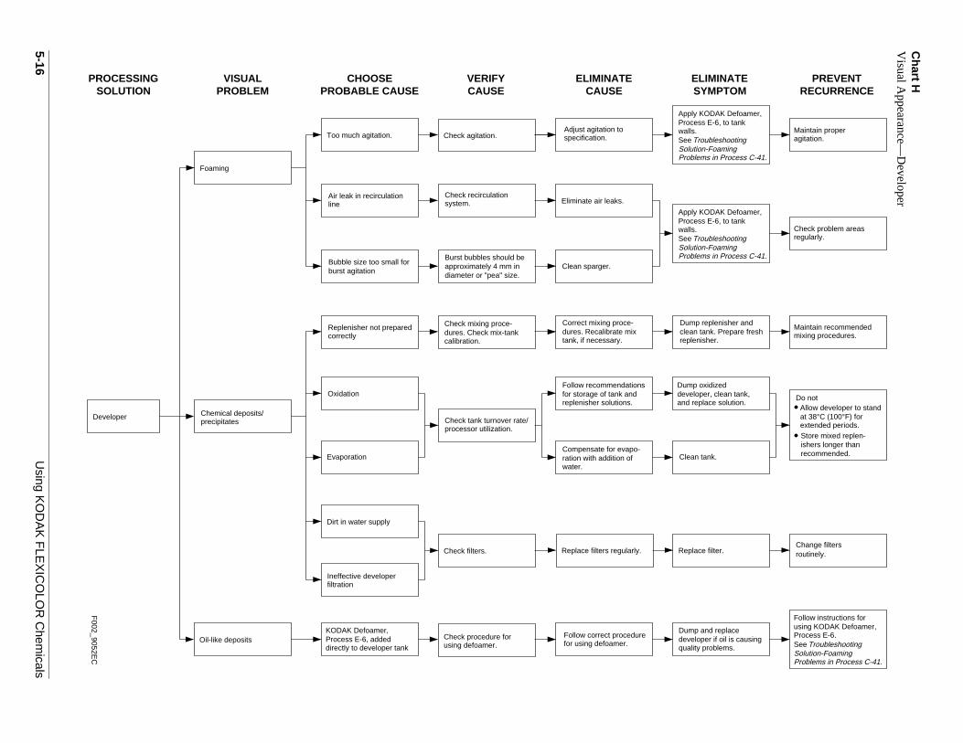
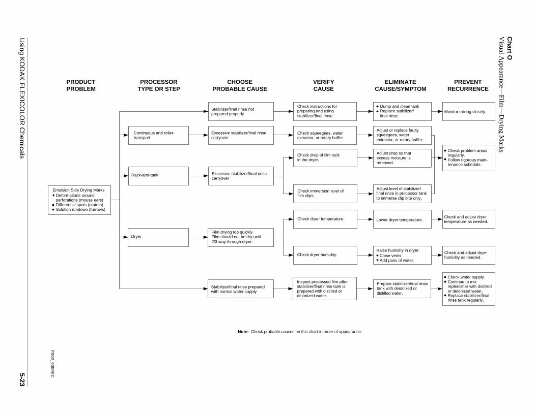
DIAGNOSTIC CHARTSThe diagrams in this section provide you with a step-by-steapproach to diagnosing processing problems. Summarycharts show which detailed chart to consult for yourproblem. The charts give probable causes and suggestcorrective procedures. Remedies for some processingproblems are described in Section 1,KODAKFLEXICOLOR Chemicals.
Chart Example
A Control-Chart Plots—Preliminary
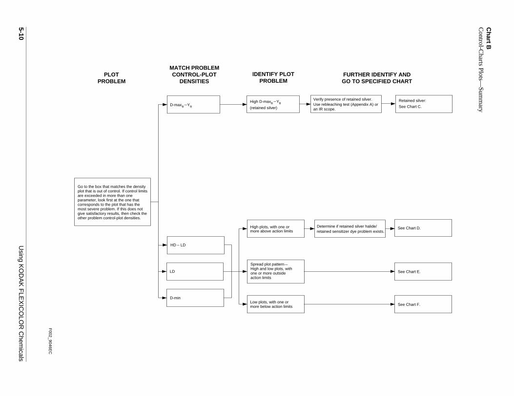
B Control-Chart Plots—Summary
C Control-Chart Plots—Retained Silver
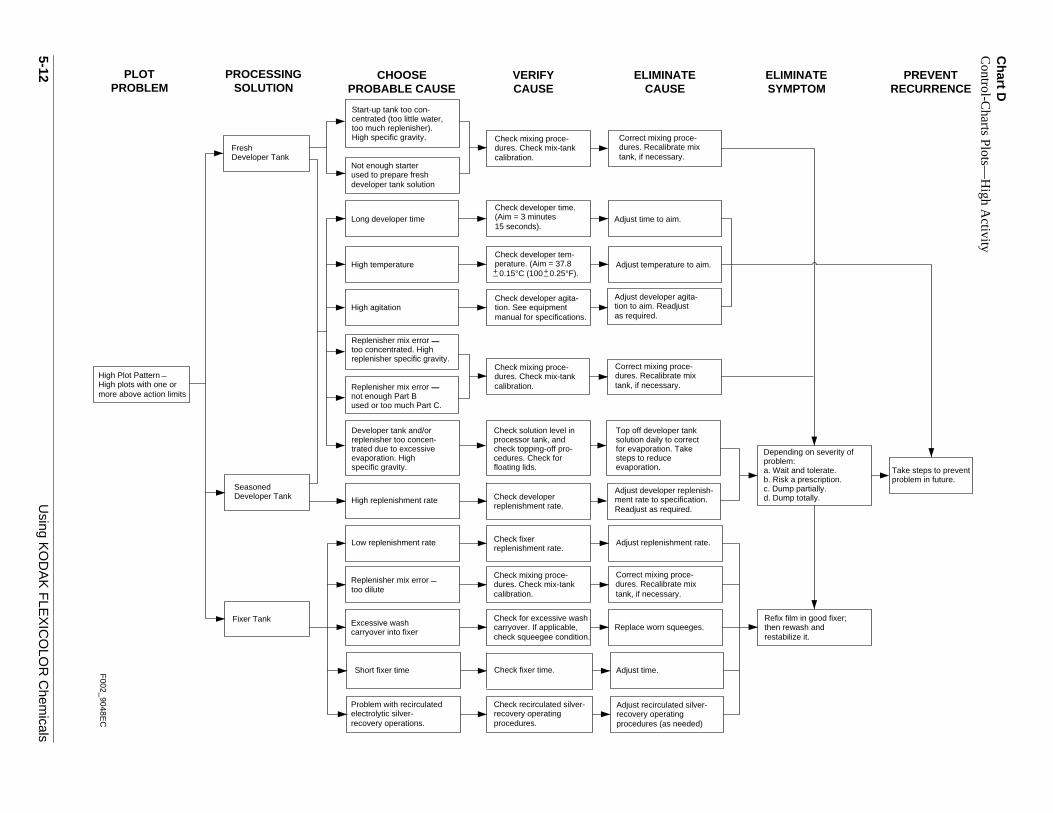
D Control-Chart Plots—High Activity
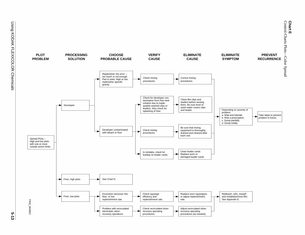
E Control-Chart Plots—Color Spread
F Control-Chart Plots—Low Activity
G Visual Appearance—Processing Solutions—Summary
H Visual Appearance—Developer
I Visual Appearance—Bleach
J Visual Appearance—Fixer, Stabilizer, and Final Rinse
K Visual Appearance—Film—Summary
L Visual Appearance—Film—Scratches and Abrasions
M Visual Appearance—Film—Surface Dirt and Adhesive Tran
N Visual Appearance—Film—Emulsion-Side Problems
O Visual Appearance—Film—Drying Marks
P Visual Appearance—Film—Scum
Q Visual Appearance—Film—Pressure Marks, Fog, Static
R Physical Appearance—Film—Sticking
5-8
Using KODAK FLEXICOLOR Chemicals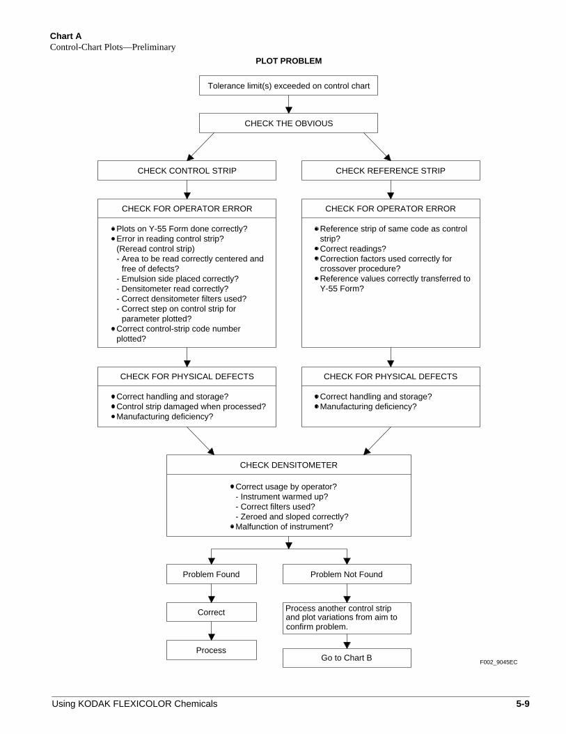
Chart AControl-Chart Plots—Preliminary
confirm problem.and plot variations from aim to Process another control strip
F002_9045EC
CHECK THE OBVIOUS
Go to Chart BProcess
Correct
Problem Not FoundProblem Found
- Zeroed and sloped correctly?Malfunction of instrument?
- Correct filters used?- Instrument warmed up?Correct usage by operator?
Correct handling and storage?Manufacturing deficiency?
CHECK FOR PHYSICAL DEFECTSCHECK FOR PHYSICAL DEFECTS
Correct handling and storage?Control strip damaged when processed?Manufacturing deficiency?
Y-55 Form?Reference values correctly transferred tocrossover procedure?
Reference strip of same code as controlstrip?Correct readings?Correction factors used correctly for
plotted?Correct control-strip code number
parameter plotted?- Correct step on control strip for- Correct densitometer filters used?- Densitometer read correctly?- Emulsion side placed correctly?
free of defects?- Area to be read correctly centered and(Reread control strip)Error in reading control strip?Plots on Y-55 Form done correctly?
CHECK FOR OPERATOR ERRORCHECK FOR OPERATOR ERROR
CHECK REFERENCE STRIPCHECK CONTROL STRIP
CHECK DENSITOMETER
Tolerance limit(s) exceeded on control chart
PLOT PROBLEM
Using KODAK FLEXICOLOR Chemicals 5-9
5-10U
sing KO
DA
K F
LEX
ICO
LOR
Chem
icals
Chart B
Control-C
harts Plots—
Sum
mary
lide/m exists.
See Chart F.
See Chart E.
See Chart C. A) orRetained silver:r.
ECIFIED CHART IDENTIFY AND
See Chart D.
High D-max YB B
F002_9046E
C
B B (retained silver)
Determine if retained silver haretained sensitizer dye proble
D-min
HD LD
other problem control-plot densities.give satisfactory results, then check themost severe problem. If this does notcorresponds to the plot that has theparameter, look first at the one thatare exceeded in more than oneplot that is out of control. If control limitsGo to the box that matches the density
an IR scope.Use rebleaching test (AppendixD-max YVerify presence of retained silve
PLOTPROBLEM
MATCH PROBLEMCONTROL-PLOT
DENSITIES PROBLEMIDENTIFY PLOT
GO TO SPFURTHER
High plots, with one ormore above action limits
LD
Low plots, with one ormore below action limits
one or more outsideHigh and low plots, with
action limits
Spread plot pattern

Using K
OD
AK
FLE
XIC
OLO
R C
hemicals
5-11
Chart C
Control-C
harts Plots—
Retained S
ilver
YMPTOMLIMINATE
RECURRENCEPREVENT
problem in future.Take steps to prevent
Dump partially.Dump totally.
oblem:pending on severity of
Wait and tolerate.Risk a prescription.
CHOOSEPROBABLE CAUSE CAUSE
VERIFYCAUSE
ELIMINATESE
SOLUTIONPROCESSING
Fresh Bleach Tank
Bleach dilution due tohigh developer carryover.High pH and low totaliron.
Too much FLEXICOLORBleach Starter used in
Seasoned Bleach Tank
Excessively low bleachagitation
Check developersqueegees. Check
Check agitation.
if worn.Replace squeegees
water used to prepareMix error too much
replenishment rate.Check bleach
developer carryover.
replenisher. Freshtank prepared withregenerated replenishertreated with too littleregenerator (low mix ratio).High pH and low total iron.
fresh tank mix. High pH.
Check mixing proce-dures. Check mix-tankcalibration.
Correct mixing proce-dures. Recalibrate mixtank, if necessary.
PLOTPROBLEM
c. d.
prDe
a. b.
Very short bleach time Check bleach time. Adjust time if required.
bleach doesn’t splashinto developer).
Increase agitation (butcheck to be sure that
Low total iron and lowspecific gravity.
Too much water in freshtank or replenisher mix.
gravity.
tank or replenisher mix.Too little Part A in fresh
High pH and low specific
specific gravity.
tank or replenisher mix.Too little Part B in fresh
Low total iron and low
Too little regenerator
isher (low mix ratio). HighpH, low total iron, andlow specific gravity.
used to prepare replen-
Check mixing proce-dures. Check mix-tankcalibration. tank if necessary.
dures. Recalibrate mixCorrect mixing proce-
Low bleach replenish-ment rate. High pH andlow total iron.
Adjust bleachreplenishment rateto specifications.
Bleach dilution due toaddition of too muchwater. Low total iron andlow specific gravity.
Eliminate leaks. Becareful not to add excesswater for solution lossdue to evaporation.in tempering system.
water, check for leakstempered with warmand leaks. If bleach isCheck water additions
B B
(retained silver)
High D-max Y
F002_9047E
C
5-12U
sing KO
DA
K F
LEX
ICO
LOR
Chem
icals
Chart D
Control-C
harts Plots—
High A
ctivity
restabilize it.then rewash andRefix film in good fixer;
SYMPTOMELIMINATE
RECURRENCEPREVENT
problem in future.Take steps to prevent
c. Dump partially.d. Dump totally.
problem:Depending on severity of
a. Wait and tolerate.b. Risk a prescription.
_+_+
F002_9048E
C
Developer TankSeasoned
procedures (as needed)recovery operatingAdjust recirculated silver-
procedures.recovery operatingCheck recirculated silver-
recovery operations.electrolytic silver-Problem with recirculated
Replace worn squeeges.check squeegee condition.
carryover into fixerExcessive wash
Correct mixing proce-
tank, if necessary.calibration.
Check fixer time.Short fixer time Adjust time.
carryover. If applicable,Check for excessive wash
dures. Recalibrate mixdures. Check mix-tankCheck mixing proce-
Replenisher mix error
Readjust as required.
Adjust developer replenish-Check developerreplenishment rate.
High replenishment rate ment rate to specification.
Top off developer tanksolution daily to correct
steps to reduceevaporation.
for evaporation. Take
Check solution level inprocessor tank, and
cedures. Check forfloating lids.
check topping-off pro-
High agitationas required.tion to aim. ReadjustAdjust developer agita-
0.15°C (100 0.25°F).perature. (Aim = 37.8Check developer tem-
manual for specifications.tion. See equipment Check developer agita-
15 seconds).(Aim = 3 minutesCheck developer time.
Long developer time Adjust time to aim.
Not enough starterused to prepare freshdeveloper tank solution
too much replenisher).
Start-up tank too con-centrated (too little water,
High specific gravity.
Developer TankFresh
more above action limitsHigh plots with one orHigh Plot Pattern
CHOOSEPROBABLE CAUSE CAUSE
VERIFYCAUSE
ELIMINATESOLUTION
PROCESSING
Fixer Tank
replenishment rate.Check fixer
Check mixing proce-dures. Check mix-tankcalibration.
Correct mixing proce-dures. Recalibrate mixtank, if necessary.
PLOTPROBLEM
High temperature Adjust temperature to aim.
too concentrated. HighReplenisher mix error
replenisher specific gravity.
not enough Part BReplenisher mix error
used or too much Part C.
Developer tank and/or
trated due to excessiveevaporation. Highspecific gravity.
replenisher too concen-
Check mixing proce-dures. Check mix-tankcalibration. tank, if necessary.
dures. Recalibrate mixCorrect mixing proce-
Low replenishment rate Adjust replenishment rate.
too dilute
_
_
_
Using K
OD
AK
FLE
XIC
OLO
R C
hemicals
5-13
Chart E
Control-C
harts Plots—
Color S
pread
ee Appendix E.nd restabilize/rinse film.ebleach, refix, rewash
YMPTOMLIMINATE
RECURRENCEPREVENT
problem in future.Take steps to prevent
Dump partially.. Dump totally.
roblem:epending on severity of
. Wait and tolerate.
. Risk a prescription.
SaR
replenishment rate.effciency andCheck squeege
replenishment ratefixer, or lowExcessive carryover into
rate.or adjust replenishmentReplace worn squeegees
Fixer, low plots
F002_9049E
C
with one or more
Spread PlotsHigh and low plots
outside action limits
buildup on leader cards.In minilabs, check for
See Chart D.
Clean film clips andleaders before reusingthem. Be sure level of
and leader.wash water covers clips
solution due to inade-tamination from fixer tank
quately washed clips or
splashing of fixer.leaders. Also check for
Check for developer con-
Clean leader cards.Replace worn ordamaged leader cards.
procedures.procedures.
CHOOSEPROBABLE CAUSE CAUSE
VERIFYCAUSE
ELIMINATESE
SOLUTIONPROCESSING
Developer
Fixer, high plots
PLOTPROBLEM
c.d
pD
ab
Check mixing Correct mixing
Replenisher mix error
Part A used. High or lowreplenisher specificgravity.
too much or not enough
Check mixing procedures.
Developer contaminatedwith bleach or fixer
Be sure that mixingequipment is thoroughlydrained and cleaned aftereach use.
_
Check recirculated silver-recovery operatingprocedures.
electrolytic silver-Problem with recirculated
recovery operations
Adjust recirculated silver-recovery operatingprocedures (as needed).

5-14U
sing KO
DA
K F
LEX
ICO
LOR
Chem
icals
Chart F
Control-C
harts Plots—
Low A
ctivity
SYMPTOMELIMINATE
RECURRENCEPREVENT
problem in future.Take steps to prevent
c. Dump partially.d. Dump totally.
problem:Depending on severity of
a. Wait and tolerate.b. Risk a prescription.
0.15°Ctemperature
Readjust as required.Developer TankSeasoned
replenisherdeveloper or developerAerial oxidation of
ishment rate to aim.Adjust developer replen-
carryover into fixerExcessive wash
and film population.Check replenishment rate
Check mixingprocedures.
Low developer agitationas required.specification. ReadjustAdjust agitation to
equipment manual for Check agitation. See
specifications.
Aim = 37.8Check developer temperature.
Check rack threading on(Aim = 3 minutes 15 seconds).Check developer time.
Short developer time
Start-up tank highstarter concentration
replenisher). Low specific
Start-up tank too dilute(too much water, too little
gravity.
Developer TankFresh
more outside action limitsLow plots with one orLow Plot Pattern
CHOOSEPROBABLE CAUSE CAUSE
VERIFYCAUSE
ELIMINATESOLUTION
PROCESSING
Check mixing procedures.Check mix-tank calibration.
Correct mixing proce-dures. Recalibrate mixtank, if necessary.
PLOTPROBLEM
Low developer
developer or developerBleach contamination of
replenisher
too dilute. Low replen-Replenisher mix error
isher specific gravity.
Replenisher mix error
High replenisher specificgravity.
too much Part B used.
continuous processor.
mixing procedures.bleach tank. CheckCheck for splashing from
bleach, if required. CorrectAdjust air agitation in
mixing procedures.
Check mixing procedures.Check mix-tank calibration.
Correct mixing proce-dures. Recalibrate mixtank, if necessary.
Adjust developer temperature to aim.Readjust as required.
Adjust developer time toaim. Rethread rack, Ifnecessary.
Replenisher mix error
Low replenisher specificgravity.
not enough Part C used.
Correct mixingprocedures.
Working tank solutiondiluted by excessivewater top-off or leak.Low specific gravity.
Check procedures usedto compensate for evap-oration. Check solutiontempering equipment.
Correct operatingpractices, as required.Repair faulty equipment.
Check for air trapped in devel-oper recirculation system.Confirm that nitrogen wasused for agitation.Check mixing procedures.Was too much air drawn intosolution?Check for air drawn in by rollersin roller-transport processors.Check for low utilization.
Correct leak in recirculationsystem.Use nitrogen for gaseous-burst agitation.Correct mixing procedures.Minimize time that drive is onand rollers are turning inroller-transport processors.
F002_9050E
C
_+_+
(100 0.25°F).
See Chart E.Fixer Tank
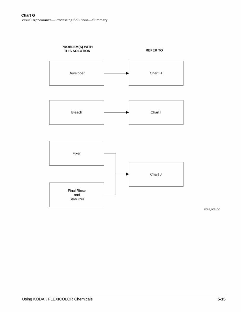
Chart GVisual Appearance—Processing Solutions—Summary
Stabilizerand
Final Rinse
F002_9051DC
Developer
Bleach
Fixer
Chart H
Chart I
Chart J
THIS SOLUTIONPROBLEM(S) WITH
REFER TO
Using KODAK FLEXICOLOR Chemicals 5-15
5-16U
sing KO
DA
K F
LEX
ICO
LOR
Chem
icals
Chart H
Visual A
ppearance—D
eveloper
Problems in Process C-41.Solution-Foaming Troubleshooting
blems in Process C-41.tion-Foaming
Troubleshooting
blems in Process C-41.tion-Foaming
Troubleshooting
See
s.
ly KODAK Defoamer,cess E-6, to tank
routinely.Change filters
an tank.
Process E-6.using KODAK Defoamer,Follow instructions for
lity problems.eloper if oil is causingp and replace
replace solution.loper, clean tank,p oxidized
lenisher.n tank. Prepare freshp replenisher and
s.
ly KODAK Defoamer,
lace filter.
mixing procedures.Maintain recommended
Check problem areasregularly.
agitation.Maintain proper
PREVENTRECURRENCE
ELIMINATESYMPTOM
cess E-6, to tank
Do notAllow developer to standat 38°C (100°F) forextended periods.Store mixed replen-ishers longer thanrecommended.
ProSolu
ProSolu
wall
AppPro
See
See
F002_9052E
C
Cle
Oxidation
Evaporation
quadevDum
directly to developer tankProcess E-6, addedKODAK Defoamer,
and deveDum
water.ration with addition ofCompensate for evapo-
replenisher solutions.for storage of tank andFollow recommendations
repcleaDum
tank, if necessary.dures. Recalibrate mixCorrect mixing proce-
calibration.dures. Check mix-tankCheck mixing proce-
for using defoamer.Follow correct procedure
using defoamer.Check procedure for
filtrationIneffective developer
processor utilization.Check tank turnover rate/
correctlyReplenisher not prepared
lineAir leak in recirculation
system.Check recirculation
wall
App
specification.Adjust agitation to
RepReplace filters regularly.Check filters.
Dirt in water supply
Eliminate air leaks.
Check agitation.
precipitatesChemical deposits/
ELIMINATECAUSE
VERIFYCAUSEPROBABLE CAUSE
CHOOSEPROBLEM
VISUALPROCESSINGSOLUTION
Too much agitation.
Foaming
Pro
Developer
Oil-like deposits
Bubble size too small for burst agitation
Burst bubbles should beapproximately 4 mm indiameter or "pea" size.
Clean sparger.

Using K
OD
AK
FLE
XIC
OLO
R C
hemicals
5-17
Chart I
Visual A
ppearance—B
leach
Problems in Process C-41.Solution-Foaming Troubleshooting
ms in Process C-41.n-Foamingoubleshooting
ms in Process C-41.n-Foamingoubleshooting
Process E-6.
Follow instructions for
See
using KODAK Defoamer,
s E-6, to tankKODAK Defoamer,
KODAK Defoamer,s E-6, to tank
er and Neutralizer.loper System tanks with KODAK
bleach aeration.Maintain proper
Maintain squeegees.
bleach system.phosphates fromRemove sources of
ing problems.h if precipitate is and replace
ng problems.h if sludge is and replace
y problems.h if oil is causing and replace
Check problem areasregularly.
aeration.Maintain proper
PREVENTRECURRENCE
IMINATEYMPTOM
y problems. Cleanh if tar is causing and replace
Use warm water totop off bleach tank.
ProbleSolutio Tr
ProbleSolutio Tr
walls.Proces
See
Apply
walls.See
Apply Proces
CleanDevetar in
causbleacDump
bleachfrom cleaning agents toAddition of phosphate
causibleacDump
to top off bleach tank.Use correct procedure
qualitbleacDump
for using defoamer.Use correct procedure
using defoamer.Check procedure for
Change cleaning agents.procedures.Check cleaning
lineAir leak in recirculation
system.Check recirculation
specification.Adjust aeration to
Check aeration.
Eliminate air leaks.
Check aeration.
Brown "mud"
ELS
ELIMINATECAUSE
VERIFYCAUSEPROBABLE CAUSE
CHOOSEPROBLEM
VISUALPROCESSINGSOLUTION
Too much aeration
Foaming
Bleach
Yellow "gel" precipitate
Oil-like deposits
Tar
topping off bleach tank.Check procedure for
Check squeegees.
qualitbleacDump
Too much KODAKDefoamer, Process E-6,used
Addition of cold water totop off bleach tank
carryoverExcessive developer
squeegees.Replace worn
Excessive bleachaeration
Adjust aeration tospecifications.
F002_9053E
C

5-18U
sing KO
DA
K F
LEX
ICO
LOR
Chem
icals
Chart J
Visual A
ppearance—F
ixer, Stabilizer, and F
inal Rinse
tank frequently. Dump stabilizer/final rinse
rate regularly. Check filter regularly.
Check replenishment
rate regularly.
Drain wash tank nightly at shutdown.
Replace wash filter regularly.
Check wash water flow
Eliminate air leaks.
Check problemareas regularly.
SYMPTOMELIMINATE
RECURRENCEPREVENT
Dump sulfurized fixer.
Allow solution to standprior to processing filmif foam causes qualityproblems.
tank
Final Wash
Dump stabilizer/final rinse tank. Follow instructions under
Replace filter. Adjust replenishment rate.
Removing Biological Growth.
precipitate. Biological growth Low replenishmentDirt in stabilizer/final rinse
Clogged recirculation filter rate.
Check tank for "greasy"
Check replenishment
clogged filter. Check for dirty or
Dump and clean wash tank.
Removing Biological Growth. Replace filter.
Follow instructions under
Adjust wash-water rate.
precipitate. Check tank for "greasy"
rate.
clogged filter.
Check for wash-water
Check for dirty or Clogged water filter Biological growth
Low wash-water rateDirt in final wash
_from electrolytic
New tank solution mixed
Foaming
time.Foam will dissipate with
Occasionally checkrecirculation system.system
Air leak in recirculation
Check silver-recoveryoperations.
Fixer
SOLUTIONPROCESSING VISUAL
PROBLEMCHOOSE
PROBABLE CAUSE CAUSEVERIFY
CAUSEELIMINATE
Sulfurization due to: Long standing time
utilizationtate in processor tankor grayish-black precipi-tate in replenisher tankYellowish-white precipi-
Check fixer usage.
processor utilization.turnover rate andtimes. Maximize tankAvoid long standing
excessive current
silver recovery.
density low sulfite, with
Sulfurization due to
recirculated electrolytic
Grayish-white or blackprecipitate
procedures.Maintain acceptablerecovery operations.Assess/adjust silver-Recirculated fixer
silver-recovery unit
Check recirculationsystem.
F002_9054E
C
Low turnover rate/low
Final Rinse and Stabilizer

Chart KVisual Appearance—Film—Summary
Chart RFilm sticking
Scratches and abrasions
PRODUCT PROBLEM REFER TO
Chart L
Surface dirt
Chart M
Emulsion-side problems
Adhesive transfer
Chart N
Pressure marks (kinks)
Scum on base
Drying marks
Chart P
Chart O
Static marks
Light fog Chart Q
Visual appearance of
F002_9055EC
processed film
Using KODAK FLEXICOLOR Chemicals 5-19

5-20U
sing KO
DA
K F
LEX
ICO
LOR
Chem
icals
Chart L
Visual A
ppearance—F
ilm—
Scratches and A
brasions
maintenance scheduleFollow rigorousregularlyCheck problem areas
5976 and inspect results.Machine Test LeaderKODAK FLEXICOLORProcess film or run
PREVENTRECURRENCE
F002_9056E
C alignment of parts.
splicer.
alignment of parts.
and racks regularly.Clean rollers, squeegees,Clean dirty equipment.
Remove obstruction.
before processing film.rollers. Run cleanup sheets
Check for worn parts.
Check for worn parts.
Adjust splicer.Check operation of
Splicing problems
socks regularly. Clean dryer
Replace worn parts.
Adjust to eliminate flutter.
Clean and replace roller
Maintain equipment.
Realign to specifications.
Check roller socks.
Check for flutter in dryer.
Check for proper
Roller-Transport
Chemical or dirt buildup
Processor problems
PRODUCTPROBLEM
PROCESSORTYPE
ELIMINATECAUSE/SYMPTOM
VERIFYCAUSEPROBABLE CAUSE
CHOOSE
Film tanglingRack-and-Tank
film, and rack parts.Check for clips, jammedObstruction in machine.
Check all tanks and dryer.
Check agitation.
Check rack lift.
Set proper agitation.
Correct lift problem.Maintain equipment.
Check loading technique. loading.Use caution when
Loading problem
Replace worn parts.Maintain equipment.
Chemical or dirt buildup squeegees, and racks.Check rollers,
Processor problems Check for flutter in dryer. Adjust to eliminate flutter.
Check for properRealign to specifications.
ContinuousAbrasions on FilmScratches and
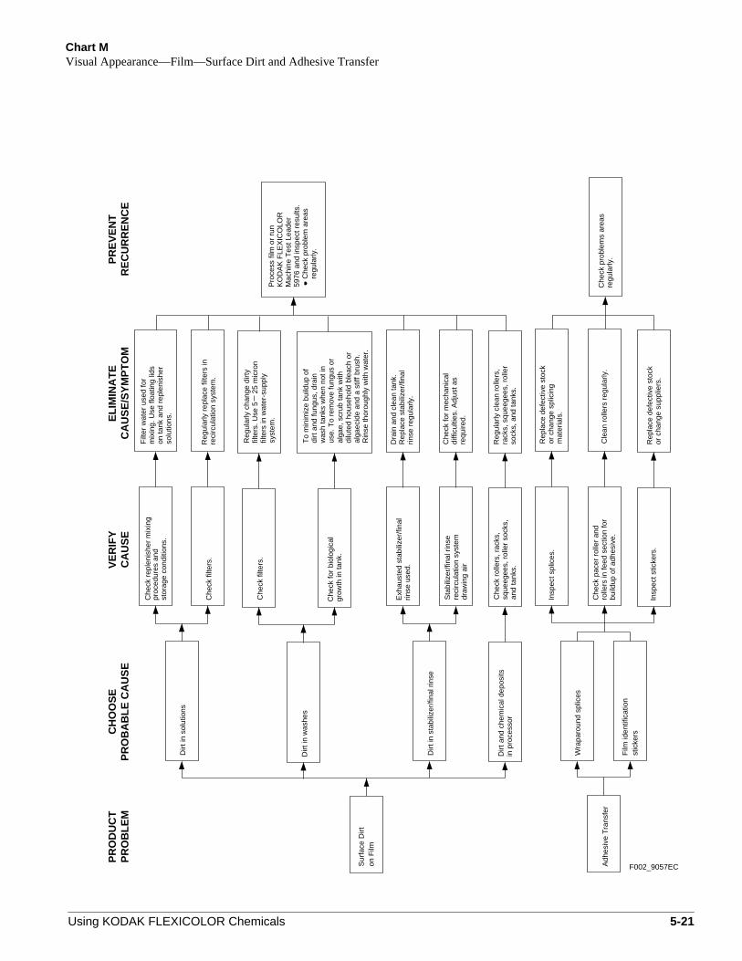
Chart MVisual Appearance—Film—Surface Dirt and Adhesive Transfer
Wra
paro
und
splic
es
Film
iden
tific
atio
n
Che
ck p
robl
ems
area
sre
gula
rly.
Sur
face
Dirt
Dra
in a
nd c
lean
tank
.R
epla
ce s
tabi
lizer
/fina
lrin
se r
egul
arly
.
Dirt
in s
tabi
lizer
/fina
l rin
se
regu
larly
.C
heck
pro
blem
are
as59
76 a
nd in
spec
t res
ults
.M
achi
ne T
est L
eade
rK
OD
AK
FLE
XIC
OLO
RP
roce
ss fi
lm o
r ru
n
Che
ck fo
r bi
olog
ical
grow
th in
tank
.
Dirt
in w
ashe
s
Che
ck fi
lters
.
Dirt
in s
olut
ions
Che
ck r
eple
nish
er m
ixin
g
PR
OB
LE
MP
RO
DU
CT
solu
tions
.
mix
ing.
Use
floa
ting
lids
Filt
er w
ater
use
d fo
r
on ta
nk a
nd r
eple
nish
er
Reg
ular
ly r
epla
ce fi
lters
inre
circ
ulat
ion
syst
em.
Che
ck fi
lters
.
CH
OO
SE
PR
OB
AB
LE
CA
US
EC
AU
SE
VE
RIF
YC
AU
SE
/SY
MP
TO
ME
LIM
INA
TE
RE
CU
RR
EN
CE
PR
EV
EN
T
on F
ilm
stic
kers
proc
edur
es a
ndst
orag
e co
nditi
ons.
syst
em.
filte
rs. U
se 5
2
5 m
icro
nR
egul
arly
cha
nge
dirt
y
filte
rs in
wat
er-s
uppl
y
dirt
and
fung
us, d
rain
To
min
imiz
e bu
ildup
of
use.
To
rem
ove
fung
us o
rw
ash
tank
s w
hen
not i
n
dilu
ted
hous
ehol
d bl
each
or
alga
e, s
crub
tank
with
Rin
se th
orou
ghly
with
wat
er.
alga
ecid
e an
d a
stiff
bru
sh.
in p
roce
ssor
Dirt
and
che
mic
al d
epos
its
Insp
ect s
ticke
rs.
Che
ck p
acer
rol
ler
and
build
up o
f adh
esiv
e.ro
llers
in fe
ed s
ectio
n fo
r
Insp
ect s
plic
es.
or c
hang
e su
pplie
rs.
Rep
lace
def
ectiv
e st
ock
Cle
an r
olle
rs r
egul
arly
.A
dhes
ive
Tra
nsfe
r
Rep
lace
def
ectiv
e st
ock
or c
hang
e sp
licin
gm
ater
ials
.
Che
ck fo
r m
echa
nica
ldi
fficu
lties
. Adj
ust a
sre
quire
d.
Che
ck r
olle
rs, r
acks
,sq
ueeg
ees,
rol
ler
sock
s,an
d ta
nks.
Reg
ular
ly c
lean
rol
lers
,ra
cks,
squ
eege
es, r
olle
rso
cks,
and
tank
s.
F002_9057EC
rinse
use
d.E
xhau
sted
sta
biliz
er/fi
nal
reci
rcul
atio
n sy
stem
Sta
biliz
er/fi
nal r
inse
draw
ing
air
Using KODAK FLEXICOLOR Chemicals 5-21

Chart NVisual Appearance—Film—Emulsion-Side Problems
elec
trol
ytic
uni
t.
For
clo
sed-
loop
sys
tem
s,
repl
enis
hmen
t rat
e.
chec
k am
pera
ge o
n
Che
ck fo
r ca
rryo
ver.
Che
ck a
nd a
djus
t
part
icle
s in
fixe
r.su
lfuriz
atio
n of
fixe
r,C
heck
for
brea
kdow
n or
Silv
er s
ulfid
e
Dev
elop
er ta
r
Dar
k D
epos
itsE
mul
sion
Sid
e:
oxid
atio
n of
dev
elop
er.
of b
leac
h.
Che
ck fo
r ox
idat
ion
of
Che
ck fo
r ov
erae
ratio
nde
velo
per.
Adj
ust a
erat
ion
of b
leac
h.
Elim
inat
e so
urce
of
See
Pro
cess
E-6
.us
ing
KO
DA
K D
efoa
mer
,ta
nk. F
ollo
w in
stru
ctio
ns fo
rD
ump
and
clea
n de
velo
per
the
film
.
Che
ck s
urfa
ce o
f dev
elop
erfo
r "o
ily"
drop
lets
, whi
ch c
anca
use
rest
rictio
n m
arks
on
KO
DA
K D
efoa
mer
Pro
cess
E-6
add
ed
solu
tion
dire
ctly
to d
evel
oper
Inst
all s
plas
h gu
ards
Adj
ust a
gita
tion
or b
urst
.be
twee
n ta
nks.
agita
tion.
of b
leac
h or
fixe
r so
lutio
n.C
heck
for
exce
ssiv
e
Che
ck fo
r sp
lash
ing
or m
istin
g fix
er s
olut
ion
prio
r to
in d
evel
oper
Spl
ashi
ng o
f ble
ach
or
film
bei
ng im
mer
sed
Min
us-D
ensi
ty S
plas
hM
arks
Em
ulsi
on S
ide:
Em
ulsi
on S
ide:
Ski
ving
s
F002_9058DC
PR
OD
UC
TP
RO
BL
EM
PR
EV
EN
TR
EC
UR
RE
NC
EE
LIM
INA
TE
CA
US
E/S
YM
PT
OM
CA
US
EV
ER
IFY
Fol
low
rig
orou
s
Che
ck p
robl
em a
reas
regu
larly
.
mai
nten
ance
sch
edul
e.
CH
OO
SE
PR
OB
AB
LE
CA
US
E
Che
ck a
lignm
ent o
f rol
lers
.of
rol
lers
Impr
oper
alig
nmen
tA
lign
film
tran
spor
t.
Em
ulsi
on S
ide:
Spl
ash
Mar
ksC
heck
pro
cess
or fo
rS
plas
hing
of s
olut
ions
on e
mul
sion
spla
shin
g.In
stal
l spl
ash
guar
dsbe
twee
n ta
nks.
(pro
cess
or p
robl
em)
Tro
uble
shoo
ting
Pro
blem
s in
Pro
cess
C-4
1.S
olut
ion-
Foa
min
g
5-22 Using KODAK FLEXICOLOR Chemicals
Using K
OD
AK
FLE
XIC
OLO
R C
hemicals
5-23
Chart O
Visual A
ppearance—F
ilm—
Drying M
arks
humidity as needed.Check and adjust dryer
temperature as needed.Check and adjust dryer
tenance schedule.Follow rigorous main-regularly.Check problem areas
/SYMPTOMIMINATE
RECURRENCEPREVENT
Monitor mixing closely.e stabilizer/and clean tank
replace faultyes, water, or rotary buffer.
op so thatoisture is
.
vel of stabilizer/ in processor tank
se clip bite only.
yer temperature.
ater. deionized orstabilizer/final rinse
se.
ns of water.ents.midity in dryer:
Check water supply.
replenisher with distilledor deionized water.
Continue to mix
rinse tank regularly.Replace stabilizer/final
F002_9059E
C
extractor, or rotary buffer.Check squeegees, water
Stabilizer/final rinse notprepared properly
PROCESSORTYPE OR STEP PROBABLE CAUSE
CHOOSECAUSEVERIFY
CAUSEEL
Inspect processed film afterstabilizer/final rinse tank isprepared with distilled ordeionized water.
carryoverExcessive stabilizer/final rinse
perforations (mouse ears)Deformations around
Emulsion Side Drying Marks
Differential spots (craters)Solution rundown (furrows)
Rack-and-tank
in the dryer.Check drop of film rack
PRODUCTPROBLEM
ReplacDump
Adjust orsqueegeextractor
Check instructions forpreparing and usingstabilizer/final rinse.
film clips.Check immersion level of
Excessive stabilizer/final rinsecarryover
Adjust drexcess mremoved
Adjust lefinal rinseto immer
Check dryer humidity.
Dryer
Check dryer temperature. Lower dr
Continuous and roller-transport
distilled wtank withPrepare
with normal water supplyStabilizer/final rinse prepared
Note: Check probable causes on this chart in order of appearance.
Film drying too quickly.Film should not be dry until2/3 way through dryer.
final rin
Add paClose v
Raise hu

5-24U
sing KO
DA
K F
LEX
ICO
LOR
Chem
icals
Chart P
Visual A
ppearance—F
ilm—
Scum
SeeProcess E-6.using KODAK Defoamer,Follow instructions for
lip bite only.or tank toel of stabilizer or final rinse
.oisture is
rop so that
tank.d clean developer
Replace stabilizer regularly.water.distilled or deionizedMix replenisher withCheck water supply.
es, vacuum squeegee,djust, or replace faulty
ffer, or squeegee roller.
film.
SE/SYMPTOMLIMINATE
RECURRENCEPREVENT
maintenance schedule.Follow rigorousregularly.Check problem areas
stabilizer/final rinse distilled or deionized
Check and adjust dryer
Check and adjust dryertemperature as needed.
humidity as needed.
yer temperature.
midity in dryer:
ans of water. vents.
Solution-FoamingProblems in Process C-41.
Troubleshooting
squeegee roller.
F002_9060E
C
immerse cin processAdjust lev
removedexcess mAdjust d
in dryer.
film clips.
carryover
or bleach for oily droplets.Check surface of developer
or bleachDump an
directly to developer orProcess E-6, addedKODAK Defoamer,
bleach solution
squeegeClean, a
rotary bucarryoverExcessive stabilizer/final rinseContinuous and
roller-transport squeegee, rotary buffer, orCheck squeegees, vacuum
To remove scum from the film, wash, repeat stabilizer/final rinse step, and dry, or clean theNote:
Scum on Film Base
PROCESSORTYPE OR STEP PROBABLE CAUSE
CHOOSECAUSEVERIFY
CAUEPRODUCT
PROBLEM
Check immersion level of
Rack-and-tank Excessive stabilizer/final rinse
Check drop of film rack
Stabilizer/final rinse preparedwith normal water supply.
deionized water.
Inspect processed film afterstabilizer/final rinse tank isprepared with distilled or
Prepare tank withwater.
Do not use FLEXICOLOR Stabilizer III in minilabs.
Check dryer temperature.
Film drying too quickly. Filmshould not be dry until 2/3way through dryer.
Check dryer humidity.
Lower dr
Raise hu
Add pClose

Chart QVisual Appearance—Film—Pressure Marks, Fog, Static
Sta
tic M
arks
*
Pre
ssur
e M
arks
(K
inks
)
PR
OB
LE
MP
RO
DU
CT
CH
OO
SE
PR
OB
AB
LE
CA
US
EC
AU
SE
VE
RIF
YC
AU
SE
/SY
MP
TO
ME
LIM
INA
TE
RE
CU
RR
EN
CE
PR
EV
EN
T
Ligh
t Fog
Han
dle
film
pro
perly
.
Che
ck fi
lter.
Impr
oper
film
han
dlin
g
Adj
ust a
nd m
aint
ain
Che
ck p
robl
em a
reas
regu
larly
.
Pro
cess
or p
robl
em
Fad
ed fi
lter
on
Saf
elig
ht u
sed
emer
genc
y in
frar
ed
Che
ck a
ll sa
felig
hts.
Che
ck d
arkr
oom
are
a.
Che
ck h
andl
ing
Che
ck s
plic
er.
Che
ck p
roce
ssor
.
Do
not u
se s
afel
ight
s.
Rep
lace
infr
ared
ligh
t
Elim
inat
e lig
ht le
aks
or
Cle
an a
nd r
epai
r eq
uip-
men
t. K
eep
equi
pmen
t
filte
r re
gula
rly o
r us
e bu
lb
Han
dle
film
pro
perly
.
indi
cato
r lig
hts.
F002_9064EC
Exc
essi
ve p
ress
ure
onfil
m p
rior
to p
roce
ssin
g
Exc
essi
ve te
nsio
non
film
Spl
icer
pro
blem
*If p
ossi
ble,
per
form
all
oper
atio
ns in
are
as th
at a
re c
ondi
tione
d at
45 to
65
perc
ent r
elat
ive
hum
idity
and
18
to 2
4°C
(65
to 7
5°F
). K
eep
the
splic
ing,
film
-load
ing,
and
pro
cess
ing
room
s as
dus
t-fr
ee a
s po
ssib
le.
Pro
vide
a g
ood
elec
tric
al g
roun
d on
you
r sp
licin
g eq
uipm
ent.
Do
not h
andl
e fil
m a
ny m
ore
than
is n
eces
sary
. Avo
id s
udde
n, q
uick
mov
emen
ts o
f the
film
that
cou
ld c
ause
fric
tion.
Avo
id w
indi
ng o
r un
win
ding
roll
film
too
tight
ly o
r to
o ra
pidl
y.
light
sou
rce
Ligh
t lea
ks o
r in
dica
tor
light
s in
spl
icin
g or
proc
essi
ng a
reas
Che
ck h
andl
ing
tech
niqu
e.
exce
ssiv
e te
nsio
n.C
heck
pro
cess
or fo
r
proc
edur
es.
of lo
wer
wat
tage
.
clea
n an
d in
goo
dw
orki
ng o
rder
.
proc
esso
r.
Using KODAK FLEXICOLOR Chemicals 5-25

5-26U
sing KO
DA
K F
LEX
ICO
LOR
Chem
icals
Chart R
Physical A
ppearance—F
ilm—
Sticking
RECURRENCEPREVENT
Check problem areasregularly.
Roller-Transport
Film Sticking
Rack-and-Tank
Rack sway in dryer
PROBLEMPRODUCT PROCESSOR
TYPECHOOSE
PROBABLE CAUSE CAUSEVERIFY
CAUSE/SYMPTOMELIMINATE
Continuous
Check dryer mechanics.
Adjust dryer temperature
Adjust to specifications.
Check dryer temperature.
Film still wet after dryerstep
Check dryer temperature.
Film still wet after dryerstep
Check dryer mechanics. Adjust to specifications.
Film jam in dryer
Film still wet after dryer
Splice marks after take-up
step
F002_9063E
C
to specifications.
Check splicer.
Check dryer mechanics.
Check dryer temperature.
Check dryer mechanics.
Check dryer transport.
Adjust to specifications.
Adjust dryer temperature
Adjust to specifications.
Adjust to specifications.
Adjust to specifications.
to specifications.
Adjust dryer temperatureto specifications.
on
n,
-rste
no.t
e
aeof
y,
r
re
:ab.
t.
n
Troubleshooting Solution-Foaming Problemsin Process C-41Foaming of process solutions can have an adverse effectthe quality of processed films, and can lead to solutioncontamination. If foaming is severe in any process solutiocheck the following:
1. Make sure that no air is being drawn into the tanksolution through the recirculation system. Air drawninto the recirculation system produces very finebubbles, which promote foaming and misting ofsolutions. Check for pinhole leaks in the line, a filterpod that is not sealed, or a loose fitting. With a rackand-tank processor, make sure that the gaseous-buagitation system is shut off when you check for thesproblems.
2. In rack-and-tank processors, make sure that thebubbles used for agitation are approximately 4 mm idiameter (“pea-sized” bubbles). Bubbles that are tosmall can promote foaming and misting of solutionsSmall bubbles usually result from sparger holes thaare too small or from holes that are restricted bychemical residue. To reduce the tendency for residuto build up in sparger holes in the developer tank,make sure to use humidified nitrogen of at least99-percent purity.
Note: When cleaning the burst sparger to removeresidue, be careful not to enlarge the holes by usingtool that is too large. Enlarged holes will produce largbubbles that can cause solution splashing at the topthe tank.
3. In rack-and-tank processors, make sure that thepressure of the burst agitation causes a maximumsolution rise of approximately 5/8 inch (1.5 cm). Toomuch pressure will make the solution rise excessivelcreating more potential for solution foaming.
4. In rack-and-tank processors with small tanks, thedeveloper tank has an increased tendency to foamwhen you use FLEXICOLOR Developer ReplenisheLORR. Try switching to the standard FLEXICOLORDeveloper Replenisher to reduce foaming (and be suto increase the developer replenishment rateaccordingly).
Using KODAK FLEXICOLOR Chemicals
As a last resort to reduce solution foaming inProcess C-41, use KODAK Defoamer, Process E-6(CAT No. 125 3566) according to the following directions
1. Use the defoamer sparingly. Use a clean cotton swto apply a thin coating on only two sides of the tankApply the defoamer at least1⁄2 inch to 1 inch above themaximum solution level. With a rack-and-tankprocessor, the maximum solution level is the highessolution level reached during a burst agitation cycle
Note: The defoamer should not come into directcontact with the process solution. If the defoamerenters the solution, it can cause “oily” deposits orprocess restriction marks on film.
2. At processor start-up each day, remove the olddefoamer from the sides of the tank(s) with a cleandamp cloth, and reapply defoamer as in described istep 1.
5-27

5
s
.
ss.r,st,r.
tion
igh
o Low/High
o Low/High
uch Part A
uch Part B
uch Part C
Too Little/Much
Too Little/Much
ation — Too Low/High
ch
r
o Low
o Low/High
CONTROL-CHART EXAMPLESThe following charts are examples of how various conditionwill affect your control plots. They are intendedonly as aguide;your plots may not look exactly like these examplesYour plots may be different because of processor andcontrol-strip differences and your processing conditions.More than one problem may also be affecting your proce
These plots are typical for a particular problem; howeveif they do not exactly match your plots, find the one that moclosely matches the predominant trend. Use these chartsalong with the diagnostic charts and the information undeInterpreting Your Control Plotto analyze process problems
Chart Solution Condi
1 Developer Temperature Too Low/H
2 Developer Time Too Short/Long
3 Developer Agitation Too Low/High
4 Developer Replenisher LORR Replenishment Rate To
5 Developer Replenisher Replenishment Rate To
6 Developer Mix Error—Too Little/M
7 Developer Mix Error—Too Little/M
8 Developer Mix Error—Too Little/M
9 Developer Starter LORR Fresh-Tank Mix Error—
10 Developer Starter Fresh-Tank Mix Error—
11 Developer Tank Solution Concentr
12 Developer Oxidation
13 Developer Contaminated with Blea
14 Developer Contaminated with Fixe
15 Bleach III Too Dilute
16 Bleach III Replenishment Rate To
17 RA Bleach Replenishment Rate To
18 Bleach III Poor Aeration
19 RA Bleach Poor Aeration
20 Bleach Stain
21 Fixer Too Dilute
22 Fixer pH Too Low
-28 Using KODAK FLEXICOLOR Chemicals

Developer—Temperature Too Low/HighDeveloper activity varies directly with temperature.High temperatures will increase the amount of dyeformed; low temperatures will decrease the amount odye formed. Check the developer temperature dailywith an accurate thermometer. Check yourtemperature control unit daily.
Out-of-control conditions due to temperaturechanges are difficult to solve. They can appear anddisappear rapidly because they are usually causedintermittent electrical or tempered-water-flowproblems. Poor tank recirculation can also causetemperature problems; insufficient dye will formwhen the temperature is not maintained uniformlythroughout the tank. Check the developer temperatuwith an accurate thermometer if your temperature-control unit indicates fluctuations.
Chart 1
Using KODAK FLEXICOLOR Chemicals
f
by
re
-4°F
(+
2.2°
C)
+4°
F (
+2.
2°C
)
BD-max Y
HD LD
0
Nor
mal
0
+B
+.05
.10
.25
.20
.15
.20
.25
.05
.10
.15
.15
.05
.10
.25
.20
0
0
+LD
+D-min
.05
.05
.05
.05
.15
.10
.10
.05
.15
.25
.10
.15
.20
5-29

Developer—Time Too Short/LongDeveloper activity varies directly with time. Anincrease in developer time produces an increase in tamount of dye formed; a decrease in developer timproduces a decrease in the amount of dye formed.
Developer time variations can occur in processorbecause of electrical-load variations and motor-temperature differences from a cold start to normaloperation. Electrical-load differences can be causeby other equipment, such as a heater on the samepower line. In some cases, you may need a voltageregulator on the drive motor to compensate forexternal voltage variations.
Mechanical problems, such as misaligned movinparts, can cause developer-time problems. Be sure tthe transport is functioning properly. Use a stopwatcto measure the developer time, and compare it withthe machine setting.
Developer-time problems occur in manualprocesses in sink lines, small tanks, or rotary-tubeprocessors because of operator error. Minimize erroby establishing reproducible techniques. Watch thetimer closely, and make sure to allow therecommended drain time as part of the developer tim
Chart 2
5-30
hee
s
d
ghath
rs
e.
-40
seco
nds
+40
sec
onds
BD-max Y
HD LD
0
Nor
mal
(3.
15)
0
+B
+.05
.10
.25
.20
.15
.20
.25
.05
.10
.15
.15
.05
.10
.25
.20
0
0
+LD
+D-min
.05
.05
.05
.05
.15
.10
.10
.05
.15
.25
.10
.15
.20
Using KODAK FLEXICOLOR Chemicals
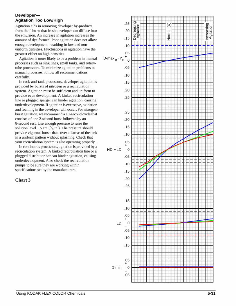
Developer—Agitation Too Low/HighAgitation aids in removing developer by-productsfrom the film so that fresh developer can diffuse intthe emulsion. An increase in agitation increases theamount of dye formed. Poor agitation does not alloenough development, resulting in low and non-uniform densities. Fluctuations in agitation have thegreatest effect on high densities.
Agitation is more likely to be a problem in manualprocesses such as sink lines, small tanks, and rotatube processors. To minimize agitation problems inmanual processes, follow all recommendationscarefully.
In rack-and-tank processors, developer agitationprovided by bursts of nitrogen or a recirculationsystem. Agitation must be sufficient and uniform toprovide even development. A kinked recirculationline or plugged sparger can hinder agitation, causinunderdevelopment. If agitation is excessive, oxidatioand foaming in the developer will occur. For nitrogenburst agitation, we recommend a 10-second cycle thconsists of one 2-second burst followed by an8-second rest. Use enough pressure to raise thesolution level 1.5 cm (5⁄8 in.). The pressure shouldprovide vigorous bursts that cover all areas of the tanin a uniform pattern without splashing. Check thatyour recirculation system is also operating properly
In continuous processors, agitation is provided byrecirculation system. A kinked recirculation line or aplugged distributor bar can hinder agitation, causinunderdevelopment. Also check the recirculationpumps to be sure they are working withinspecifications set by the manufacturers.
Chart 3
Using KODAK FLEXICOLOR Chemicals
o
w
ry-
is
gn-at
k
.a
g
HD LD
0
Incr
easi
ng
0
+
+.05
.10
.25
.20
.15
.20
.25
.05
.10
.15
.15
.05
.10
.25
.20
0
0
+LD
+D-min
.05
.05
.05
.05
.15
.10
.10
.05
.15
.25
.10
.15
.20
Nor
mal
(X
)
Agi
tatio
n
Dec
reas
ing
Agi
tatio
n
BBD-max Y
5-31

Developer Replenisher LORR—Replenishment Rate Too Low/HighDeveloper activity varies directly with the developerreplenishment rate. An overreplenished developerwill produce high dye densities; an underreplenishedeveloper will produce low dye densities. You willsee the effects of over- and underreplenishment in aof the control-plot densities.
How quickly your control plots indicate anincorrect replenishment rate depends on the tankvolume, the machine speed, and the amount of filmprocessed. Recheck the average film production thyou use to calculate the replenishment rate. Check tflowmeter or pump setting manually as described inthe processor manual; adjust it if necessary. SeeSection 2,Continuous, Roller-Transport, andRack-and-Tank Processors, for starting-pointdeveloper replenishment rates. For minilabs, seeSection 4,Minilab Processors.
Developer replenishment rates supplied for eachprocess are based on average exposures. Check yproduction; if it appears that the film has more or lesdensity than usual, adjust your developerreplenishment rate.
If overreplenishment is confirmed, adjust thedeveloper tank solution by adding a solution of onepart FLEXICOLOR Developer Starter LORR to fourparts water. Add 25 mL of this mixture per litre ofdeveloper tank solution. When you calculate the totatank volume, be sure to include tubing, temperingequipment, etc. If high activity was caused by anincorrectly mixed developer replenisher, replace thereplenisher solution.
If underreplenishment is confirmed, adjust thedeveloper tank solution by adding 25 mL of a properlmixed developer replenisher LORR per litre ofdeveloper tank solution. When you calculate the totatank volume, be sure to include tubing, temperingequipment, etc. If low activity was caused by anincorrectly mixed developer replenisher, replace thereplenisher solution.
Be sure that you do not add starter or replenishesolution close to the overflow, or you will lose theeffect of the addition if it is lost to the overflow. Turnthe recirculation on, and allow the developer to mixfor at least 15 minutes before you run a control stripMake sure your process is up to temperature beforyou run a control strip. Repeat the addition until theprocess plots within the control limits.
Chart 4
5-32
d
ll
athe
ours
l
y
l
r
.e
(0.4
X)
repl
enis
hed
Und
er-
(4.0
X)
repl
enis
hed
Ove
r-
BD-max Y
HD LD
0
Nor
mal
(X
)
0
+B
+.05
.10
.25
.20
.15
.20
.25
.05
.10
.15
.15
.05
.10
.25
.20
0
0
+LD
+D-min
.05
.05
.05
.05
.15
.10
.10
.05
.15
.25
.10
.15
.20
Using KODAK FLEXICOLOR Chemicals

Developer Replenisher—Replenishment Rate Too Low/HighDeveloper activity varies directly with the developerreplenishment rate. An overreplenished developerwill produce high dye densities; and underreplenishedeveloper will produce low dye densities. You willsee the effects of over- and underreplenishment in aof the control-plot densities.
How quickly your control plots indicate anincorrect replenishment rate depends on the tankvolume, the machine speed, and the amount of filmprocessed. Recheck the average film production thyou use to calculate the replenishment rate. Check tflowmeter or pump setting manually as described inthe processor manual; adjust it if necessary. SeeSection 2,Continuous, Roller-Transport, andRack-and-Tank Processors, for starting-pointdeveloper replenishment rates. For minilabs, seeSection 4,Minilab Processors.
Developer replenishment rates supplied for eachprocess are based on average exposures. Check yproduction; if it appears that the film has more or lesdensity than usual, adjust your developerreplenishment rate.
If overreplenishment is confirmed, adjust thedeveloper tank solution by adding a solution of onepart FLEXICOLOR Developer Starter to nine partswater. Add 25 mL of this mixture per litre ofdeveloper tank solution. When you calculate the totatank volume, be sure to include tubing, temperingequipment, etc. If high activity was caused by anincorrectly mixed developer replenisher, replace thereplenisher solution.
If underreplenishment is confirmed, adjust thedeveloper tank solution by adding 50 mL of a properlmixed developer replenisher per litre of developertank solution. When you calculate the total tankvolume, be sure to include tubing, temperingequipment, etc. If low activity was caused by anincorrectly mixed developer replenisher, replace thereplenisher solution.
Be sure that you do not add starter or replenishesolution close to the overflow, or you will lose theeffect of the addition. Turn the recirculation on, andallow the developer to mix for at least 15 minutesbefore you run a control strip. Make sure your procesis up to temperature before you run a control strip.Repeat the addition until the process plots within thcontrol limits.
Chart 5
Using KODAK FLEXICOLOR Chemicals
d
ll
athe
ours
l
y
r
s
e
.20
.15
.10
.25
.15
.05
.10
.10
.15
.05
.05
.05
.05
D-min+
LD+
0
0
.20
.25
.10
.05
.15
.15
.10
.05
.25
.20
.15
.20
.25
.10
.05+
+
0
Und
er-
0
HD LD
repl
enis
hed
(0.4
X)
Nor
mal
(X
)
Ove
r-re
plen
ishe
d(4
.0X
)
BBD-max Y
5-33

Developer—Mix Error—Too Little/Much Part AUsing an incorrect amount of Part A to preparedeveloper tank solution has the greatest effect on thigh red densities. In the HD – LD plot, the red densitwill increase dramatically when you use too muchPart A; the red density plot will decrease if you do nouse enough Part A. The green density will behave insimilar manner, but to a lesser degree. However, thblue density plot will decrease when you use too mucor too little Part A.
Check your mixing procedures. Unless you knowthe incorrect amount of Part A used, it is difficult tocorrect the mix without a chemical analysis; werecommend that you replace your developer solutio
Chart 6
5-34
hey
taeh
n.
.20
.15
.10
.25
.15
.05
.10
.10
.15
.05
.05
.05
.05
D-min+
LD+
0
0
.20
.25
.10
.05
.15
.15
.10
.05
.25
.20
.15
.20
.25
.10
.05+
+
0
0
HD LD
0.75
X
Nor
mal
(X
)
1.5X
Less More
BBD-max Y
Using KODAK FLEXICOLOR Chemicals

Developer—Mix Error—Too Little/Much Part BDeveloper activity varies inversely with the amount oPart B used to prepare developer tank solution. If thsolution is prepared with too little Part B, developeractivity will increase and more dye will form. If thesolution is mixed with too much Part B, developeractivity will decrease and less dye will form. Thedensities of the HD – LD plot will show the greatesteffects of an incorrect amount of Part B.
Check your mixing procedures. Unless you knowthe incorrect amount of Part B used, it is difficult tocorrect the mix without a chemical analysis; werecommend that you replace your developer solutio
Chart 7
Using KODAK FLEXICOLOR Chemicals
fe
n.
.20
.15
.10
.25
.15
.05
.10
.10
.15
.05
.05
.05
.05
D-min+
LD+
0
0
.20
.25
.10
.05
.15
.15
.10
.05
.25
.20
.15
.20
.25
.10
.05+
+
0
0
HD LD
No
Par
t B
Nor
mal
(X
)
2.5X
Less More
D-max YBB
5-35
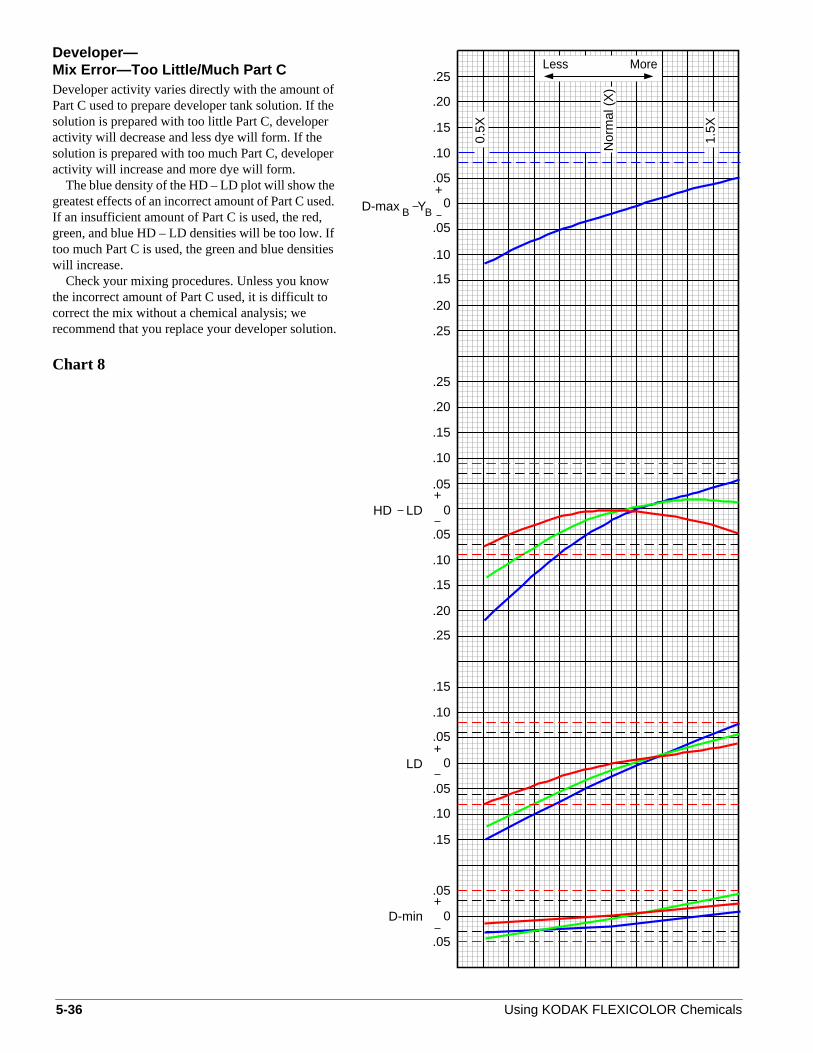
Developer—Mix Error—Too Little/Much Part CDeveloper activity varies directly with the amount ofPart C used to prepare developer tank solution. If thsolution is prepared with too little Part C, developeractivity will decrease and less dye will form. If thesolution is prepared with too much Part C, developeactivity will increase and more dye will form.
The blue density of the HD – LD plot will show thegreatest effects of an incorrect amount of Part C useIf an insufficient amount of Part C is used, the red,green, and blue HD – LD densities will be too low. Iftoo much Part C is used, the green and blue densitwill increase.
Check your mixing procedures. Unless you knowthe incorrect amount of Part C used, it is difficult tocorrect the mix without a chemical analysis; werecommend that you replace your developer solutio
Chart 8
5-36
e
r
d.
ies
n.
1.5X
More
Nor
mal
(X
)
Less.25
.20
.10
.05+
0.5X.15
.05
.10
.20
.25
.15
.25
.20
.10
+.05
.15
0
0
.05
.10
.15
.25
.20
.10
.15
.05+
.05
0LD
HD LD
.10
.15
.05+
.05
0D-min
D-max YBB
Using KODAK FLEXICOLOR Chemicals
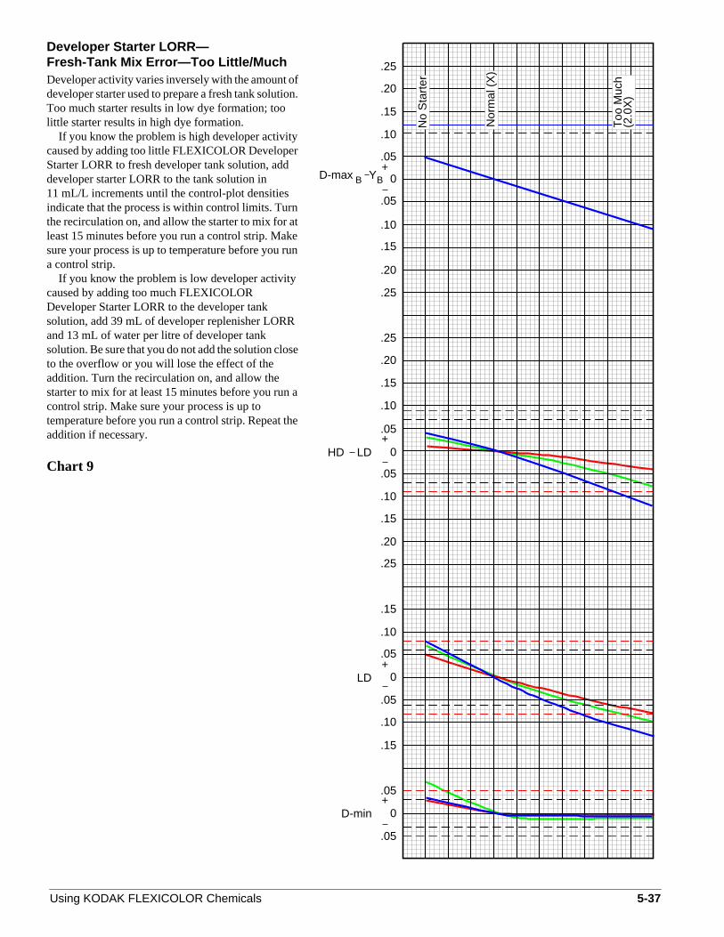
Developer Starter LORR—Fresh-Tank Mix Error—Too Little/MuchDeveloper activity varies inversely with the amount odeveloper starter used to prepare a fresh tank solutioToo much starter results in low dye formation; toolittle starter results in high dye formation.
If you know the problem is high developer activitycaused by adding too little FLEXICOLOR DeveloperStarter LORR to fresh developer tank solution, adddeveloper starter LORR to the tank solution in11 mL/L increments until the control-plot densitiesindicate that the process is within control limits. Turnthe recirculation on, and allow the starter to mix for aleast 15 minutes before you run a control strip. Maksure your process is up to temperature before you rua control strip.
If you know the problem is low developer activitycaused by adding too much FLEXICOLORDeveloper Starter LORR to the developer tanksolution, add 39 mL of developer replenisher LORRand 13 mL of water per litre of developer tanksolution. Be sure that you do not add the solution closto the overflow or you will lose the effect of theaddition. Turn the recirculation on, and allow thestarter to mix for at least 15 minutes before you runcontrol strip. Make sure your process is up totemperature before you run a control strip. Repeat thaddition if necessary.
Chart 9
Using KODAK FLEXICOLOR Chemicals
fn.
ten
e
a
e
(2.0
X)
Too
Muc
h
Nor
mal
(X
)
No
Sta
rter
HD LD
0
0
+
+.05
.10
.25
.20
.15
.20
.25
.05
.10
.15
.15
.05
.10
.25
.20
0
0
+LD
+D-min
.05
.05
.05
.05
.15
.10
.10
.05
.15
.25
.10
.15
.20
D-max YBB
5-37

Developer Starter—Fresh-Tank Mix Error—Too Little/MuchDeveloper activity varies inversely with the amount odeveloper starter used to prepare a fresh tank solutioToo much starter results in low dye formation; toolittle starter results in high dye formation.
If you know the problem is high developer activitycaused by adding too little FLEXICOLOR DeveloperStarter to fresh developer tank solution, add developstarter to the tank solution in 5.5 mL/L incrementsuntil the control-plot densities indicate that theprocess is within control limits. Turn the recirculationon, and allow the starter to mix for at least 15 minutebefore you run a control strip. Make sure your procesis up to temperature before you run a control strip.
If you know the problem is low developer activitycaused by adding too much FLEXICOLORDeveloper Starter to the developer tank solution, ad43.6 mL of developer replenisher and 6.4 mL of wateper litre of developer tank solution. Be sure that youdo not add the solution close to the overflow, or youwill lose the effect of the addition. Turn therecirculation on, and allow the starter to mix for atleast 15 minutes before you run a control strip. Maksure your process is up to temperature before you rua control strip. Repeat the addition if necessary.
Chart 10
5-38
fn.
er
ss
dr
en
(5.0
X)
Too
Muc
h
Nor
mal
(X
)
No
Sta
rter
HD LD
0
0
+
+.05
.10
.25
.20
.15
.20
.25
.05
.10
.15
.15
.05
.10
.25
.20
0
0
+LD
+D-min
.05
.05
.05
.05
.15
.10
.10
.05
.15
.25
.10
.15
.20
D-max YBB
Using KODAK FLEXICOLOR Chemicals

Developer—Tank Solution Concentration—Too Low/HighWhen you prepare a fresh developer tank solution, thamount of water you use affects the developerconcentration. If you use too much water, thedeveloper will be diluted and dye density will be low.If you do not use enough water, the developer will boverconcentrated and dye density will be high.
If you know that your process is out of controlbecause the developer tank solution is diluted, replathe tank solution.
If your control plot indicates that the tank solutionis overconcentrated, you can add water to thedeveloper tank to bring the plots within tolerance.However, unless you know the amount of water thawas omitted,do not add more than 5 percent of thetotal tank volume to correct the concentration.
In seasoned tank solutions, evaporation causesincreased developer concentration and dye densityThis is especially true in low-utilization operations.Be sure to top off your tank solution with water dailyat start-up.
You can monitor the concentration of yourdeveloper tank solution by making specific-gravitymeasurements with a hydrometer (seeCheck YourMixes with Specific-Gravity Measurements inSection 1,KODAK FLEXICOLOR Chemicals).
Chart 11
Using KODAK FLEXICOLOR Chemicals
e
e
ce
t
.
(0.5
X)
(1.3
X)
Con
cent
rate
dT
ooNor
mal
(X
)
Too
Dilu
te
HD LD
0
0
+
+.05
.10
.25
.20
.15
.20
.25
.05
.10
.15
.15
.05
.10
.25
.20
0
0
+LD
+D-min
.05
.05
.05
.05
.15
.10
.10
.05
.15
.25
.10
.15
.20
D-max YBB
5-39

Developer—OxidationDeveloper activity can be affected by oxidation of thesolution. Increasing developer oxidation causes lesdye to form, lowering density values.
Use floating lids on all developer replenisher tanksBy protecting the developer replenisher from contawith air, you can avoid problems caused by aerialoxidation. Oxidation will occur during idle periodswhen the processor is up to temperature but is notprocessing film. This problem will be most noticeablein roller-transport and minilab processors with lowutilization. You should be able to avoid severeoxidation problems in most processors by ensuringthat at least one developer tank turnover occurs eve4 weeks.
Leaks in a recirculation line or fitting will allow airto bubble into the tank solution, causing oxidation.Check your equipment for leaks if oxidation occurs.Excessive gaseous-burst agitation in rack-and-tankprocessors can also oxidize the developer.
Chart 12
5-40
s
.ct
ry
.05
.05
.15
.10
D-min+
0
HD LD
.05
.10
.05
.15
LD+
0
.05
.25
.10
.15
.20
+0
.05
.10
.25
.20
.15
.05
.10
.20
.25
.15
B B+
0
.15
.05
.10
.25
.20
Nor
mal
Increasing Oxidation
D-max Y
Using KODAK FLEXICOLOR Chemicals
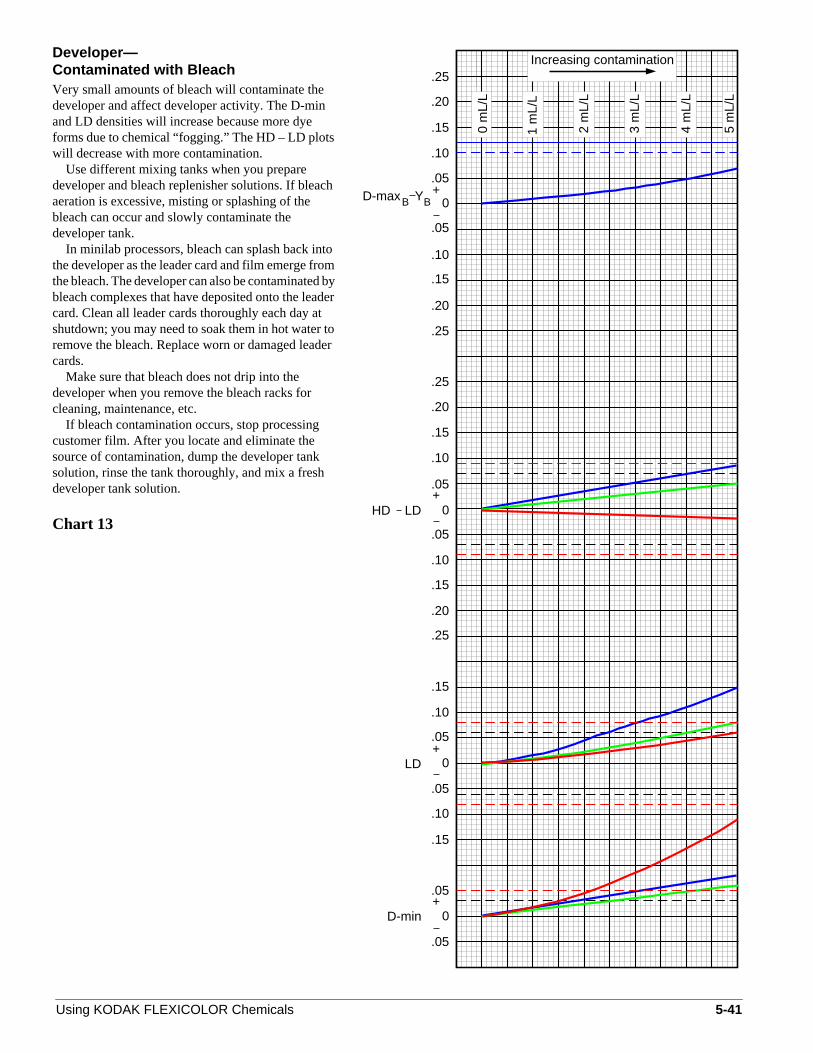
Developer—Contaminated with BleachVery small amounts of bleach will contaminate thedeveloper and affect developer activity. The D-minand LD densities will increase because more dyeforms due to chemical “fogging.” The HD – LD plotswill decrease with more contamination.
Use different mixing tanks when you preparedeveloper and bleach replenisher solutions. If bleacaeration is excessive, misting or splashing of thebleach can occur and slowly contaminate thedeveloper tank.
In minilab processors, bleach can splash back inthe developer as the leader card and film emerge frothe bleach. The developer can also be contaminatedbleach complexes that have deposited onto the leadcard. Clean all leader cards thoroughly each day atshutdown; you may need to soak them in hot water tremove the bleach. Replace worn or damaged leadcards.
Make sure that bleach does not drip into thedeveloper when you remove the bleach racks forcleaning, maintenance, etc.
If bleach contamination occurs, stop processingcustomer film. After you locate and eliminate thesource of contamination, dump the developer tanksolution, rinse the tank thoroughly, and mix a freshdeveloper tank solution.
Chart 13
Using KODAK FLEXICOLOR Chemicals
h
tombyer
oer
BD-max Y
HD LD
0
0 m
L/L
Increasing contamination
0
+B
+.05
.10
.25
.20
.15
.20
.25
.05
.10
.15
.15
.05
.10
.25
.20
0
0
+LD
+D-min
.05
.05
.05
.05
.15
.10
.10
.05
.15
.25
.10
.15
.20
1 m
L/L
2 m
L/L
5 m
L/L
3 m
L/L
4 m
L/L
5-41
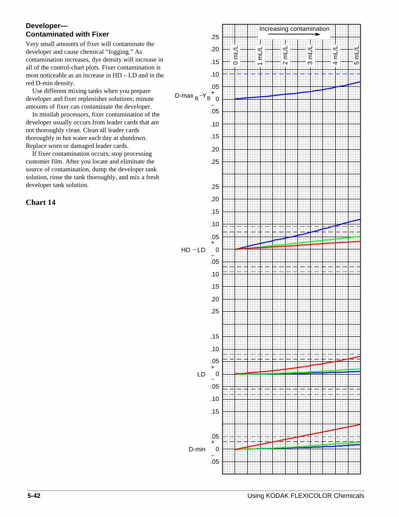
Developer—Contaminated with FixerVery small amounts of fixer will contaminate thedeveloper and cause chemical “fogging.” Ascontamination increases, dye density will increase all of the control-chart plots. Fixer contamination ismost noticeable as an increase in HD – LD and in thred D-min density.
Use different mixing tanks when you preparedeveloper and fixer replenisher solutions; minuteamounts of fixer can contaminate the developer.
In minilab processors, fixer contamination of thedeveloper usually occurs from leader cards that arenot thoroughly clean. Clean all leader cardsthoroughly in hot water each day at shutdown.Replace worn or damaged leader cards.
If fixer contamination occurs, stop processingcustomer film. After you locate and eliminate thesource of contamination, dump the developer tanksolution, rinse the tank thoroughly, and mix a freshdeveloper tank solution.
Chart 14
5-42
in
e
4 m
L/L
3 m
L/L
2 m
L/L
1 m
L/L
Increasing contamination
0 m
L/L
.15
.05
.10
.20
.25
0
.15
.25
.20
.10
.05
+
.05
.10
.15
.20
.25
0
.20
.25
.15
.10
.05
+
0LD
.15
+
.05
.05
.10
HD LD
0D-min+
.05
.05
.15
.10
5 m
L/L
BBD-max Y
Using KODAK FLEXICOLOR Chemicals
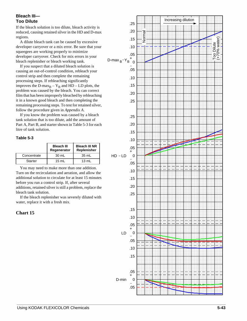
Bleach III—Too DiluteIf the bleach solution is too dilute, bleach activity isreduced, causing retained silver in the HD and D-maregions.
A dilute bleach tank can be caused by excessivedeveloper carryover or a mix error. Be sure that yousqueegees are working properly to minimizedeveloper carryover. Check for mix errors in yourbleach replenisher or bleach working tank.
If you suspect that a diluted bleach solution iscausing an out-of-control condition, rebleach yourcontrol strip and then complete the remainingprocessing steps. If rebleaching significantlyimproves the D-maxB – YB and HD – LD plots, theproblem was caused by the bleach. You can correcfilm that has been improperly bleached by rebleachinit in a known good bleach and then completing theremaining processing steps. To test for retained silvefollow the procedure given inAppendix A.
If you know the problem was caused by a bleachtank solution that is too dilute, add the amount ofPart A, Part B, and starter shown in Table 5-3 for eaclitre of tank solution.
Table 5-3
You may need to make more than one addition.Turn on the recirculation and aeration, and allow thadditional solution to circulate for at least 15 minutebefore you run a control strip. If, after severaladditions, retained silver is still a problem, replace thbleach tank solution.
If the bleach replenisher was severely diluted witwater, replace it with a fresh mix.
Chart 15
Bleach IIIRegenerator
Bleach III NRReplenisher
Concentrate 30 mL 35 mL
Starter 15 mL 13 mL
Using KODAK FLEXICOLOR Chemicals
x
r
tg
r,
h
es
e
h
(+70
% w
ater
)
Increasing dilution
Too
Dilu
te
Nor
mal
HD LD
0
0
+
+.05
.10
.25
.20
.15
.20
.25
.05
.10
.15
.15
.05
.10
.25
.20
0
0
+LD
+D-min
.05
.05
.05
.05
.15
.10
.10
.05
.15
.25
.10
.15
.20
D-max YBB
5-43

Bleach III—Replenishment Rate Too LowA low bleach replenishment rate does not adequatecompensate for developer carryover. This can redubleaching activity by diluting the bleach and raisingthe pH, causing retained silver. This is mostnoticeable as elevated plots in D-maxB – YB andHD – LD.
If you believe a problem is caused by incorrectreplenishment, check the replenishment-rate settinand reset it if necessary. Also check the developer exsqueegees to make sure they are efficient in limitindeveloper carryover.
If you have verified that retained silver is theproblem (by rebleaching or checking with an infraredscope) and it wasnot caused by inadequate aeration,add the amount of Parts A and B shown in Table 5-for each litre of tank solution.
Table 5-4
Turn on the recirculation and aeration, and allowthe additional solution to circulate for at least15 minutes before you run a control strip. Repeatthese additions until your control strips no longer havretained silver.
Chart 16
Bleach IIIRegenerator
Bleach III NRReplenisher
Concentrate 30 mL 35 mL
5-44
lyce
g,it
g
4
e
Decreasing replenishment
Nor
mal
HD LD
0
0
+
+.05
.10
.25
.20
.15
.20
.25
.05
.10
.15
.15
.05
.10
.25
.20
0
0
+LD
+D-min
.05
.05
.05
.05
.15
.10
.10
.05
.15
.25
.10
.15
.20
D-max YB B
Using KODAK FLEXICOLOR Chemicals

RA Bleach—Replenishment Rate Too Low/HighBleach activity is affected by improper replenishmenAn underreplenished bleach solution will notadequately compensate for developer carryover. ThpH of the bleach will increase and total iron willdecrease, causing retained silver.
An underreplenishment problem is most noticeablin the D-maxB – YB plot and the blue D-min density.If you think that the problem was caused by incorrecreplenishment, check that the replenishment rate asetting are correct for your processor; adjust them, necessary. Check the bleach replenishment rateregularly.
You can correct film that has been improperlybleached by rebleaching it in a known good bleachand then completing the remaining processing stepTo test for retained silver, follow the procedure givenin Appendix A.
If you have verified that retained silver is theproblem (by rebleaching or checking with an infraredscope) and it wasnot caused by inadequate aeration,add 70 mL of FLEXICOLOR RA BleachReplenisher NR for each litre of tank solution.
Turn on the recirculation and aeration, and allowthe additional solution to circulate for at least15 minutes before you run a control strip. Repeatthese additions until your control strips no longer havretained silver.
Chart 17
Using KODAK FLEXICOLOR Chemicals
t.
e
e
tndif
s.
e
.20
.15
.10
.25
.15
.05
.10
.10
.15
.05
.05
.05
.05
D-min+
LD+
0
0
.20
.25
.10
.05
.15
.15
.10
.05
.25
.20
.15
.20
.25
.10
.05+
B+
0
Nor
mal
(X
)
0
HD LD
D-max YB
Ove
r-re
plen
ishe
d(2
.0X
)
Und
er-
repl
enis
hed
(0.3
X)
5-45
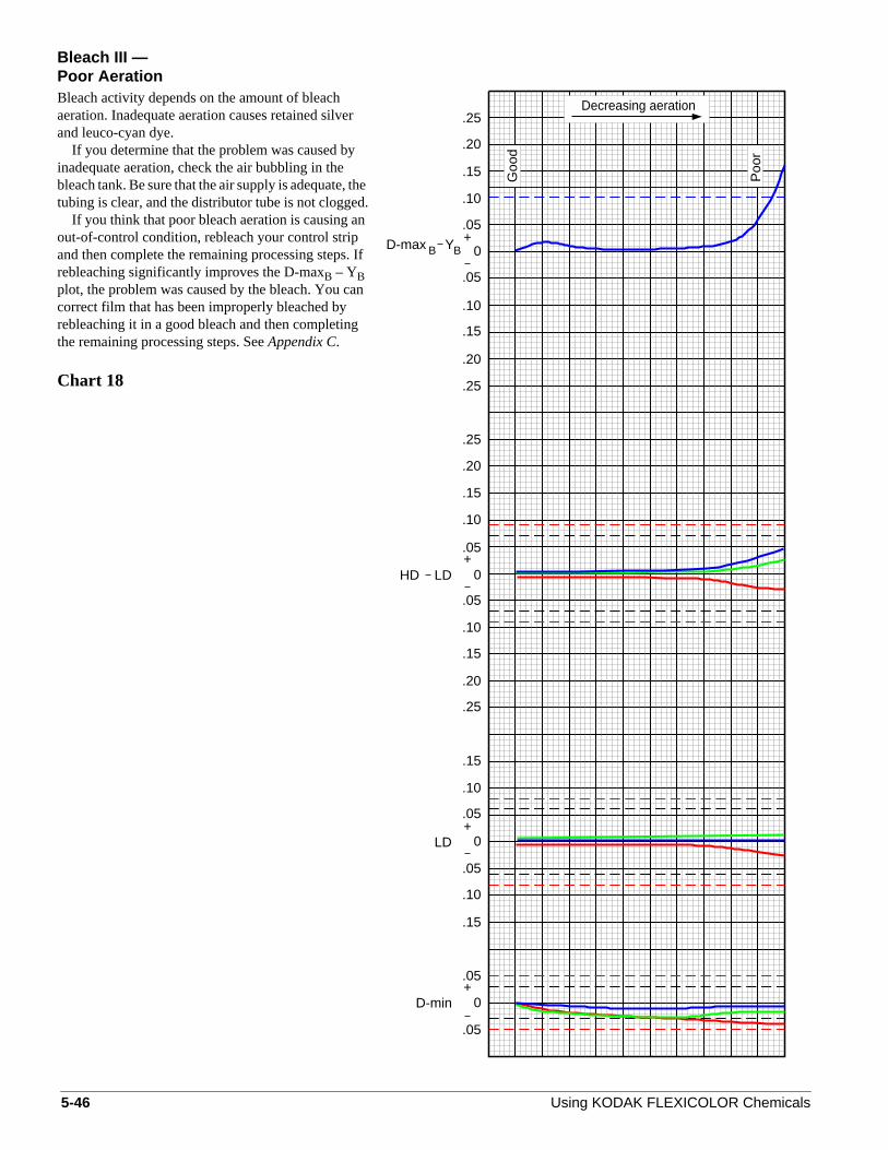
Bleach III —Poor AerationBleach activity depends on the amount of bleachaeration. Inadequate aeration causes retained silveand leuco-cyan dye.
If you determine that the problem was caused byinadequate aeration, check the air bubbling in thebleach tank. Be sure that the air supply is adequate, ttubing is clear, and the distributor tube is not clogge
If you think that poor bleach aeration is causing aout-of-control condition, rebleach your control stripand then complete the remaining processing steps.rebleaching significantly improves the D-maxB – YBplot, the problem was caused by the bleach. You cacorrect film that has been improperly bleached byrebleaching it in a good bleach and then completingthe remaining processing steps. SeeAppendix C.
Chart 18
5-46
r
hed.n
If
n
B BD-max Y
.20
.15
.10
.25
.15
.05
.10
.10
.15
.05
.05
.05
.05
D-min+
LD+
0
0
.20
.25
.10
.05
.15
.15
.10
.05
.25
.20
.15
.20
.25
.10
.05+
+
0
0
HD LD
Goo
d
Decreasing aeration
Poo
r
Using KODAK FLEXICOLOR Chemicals

RA Bleach—Poor AerationBleach activity depends on the amount of bleachaeration. Inadequate aeration causes retained silveand leuco-cyan dye.
If you determine that the problem was caused byinadequate aeration, check the air bubbling in thebleach tank. Be sure that the air supply is adequate, ttubing is clear, and the distributor tube is not clogge
If you think that poor bleach aeration is causing aout-of-control condition, rebleach your control stripand then complete the remaining processing steps.rebleaching significantly improves the D-maxB – YBplot, the problem was caused by the bleach. You cacorrect film that has been improperly bleached byrebleaching it in a good bleach and then completingthe remaining processing steps. SeeAppendix C.
Chart 19
Using KODAK FLEXICOLOR Chemicals
r
hed.n
If
n
Poo
r
Decreasing aeration
Goo
d
.20
.15
.10
.25
.15
.05
.10
.10
.15
.05
.05
.05
.05
D-min+
LD+
0
0
.20
.25
.10
.05
.15
.15
.10
.05
.25
.20
.15
.20
.25
.10
.05+
B+
0
0
HD LD
D-max YB
5-47

Bleach—StainUnder some conditions, the developing agent fromdeveloper carryover can produce a by-product thatcauses staining in the bleach. This by-product can absorbed into the film, increasing the D-min and LDdensities, especially in the green (magenta) layer.
The staining by-product is caused primarily byunderaeration of the bleach tank solution. It can alsbe caused by excessive developer carryover orunderreplenishment of the bleach tank solution.
To test for bleach stain, follow the procedure givenin Appendix B. Correct the cause of the stainingcondition; it may be necessary to dump all or part othe bleach tank solution. If staining is minimal, anactivated carbon filter in the recirculation line of thebleach may help correct the problem.
Chart 20
5-48
be
o
f
Increasing stain
HD LD
0
0
+
+.05
.10
.25
.20
.15
.20
.25
.05
.10
.15
.15
.05
.10
.25
.20
0
0
+LD
+D-min
.05
.05
.05
.05
.15
.10
.10
.05
.15
.25
.10
.15
.20
D-max YBB
Using KODAK FLEXICOLOR Chemicals

Fixer—Too DiluteModerate levels of fixer dilution cause increaseddensity in the red and green D-min and LD plots.When the fixer is extremely diluted, retained silverhalide and sensitizer dye cause increased density incontrol plots. When that occurs, the D-min areas of thfilm will appear milky.
The most probable causes of insufficient fixing arefixer dilution from excessive wash carryover, too littlefixer time, too much water used to prepare fixerreplenisher, fixer underreplenishment, and fixersulfurization.
If you think that diluted fixer is causing an out-of-control condition, refix and rewash your control stripaccording to the procedure inAppendix D. If refixingsignificantly improves the red and green D-min andLD densities, the problem was caused by the fixer.You can correct film that has been incompletely fixedby refixing and rewashing it. Be sure to eliminate theproblem that causes dilution.
Chart 21
Using KODAK FLEXICOLOR Chemicals
alle
50%
Dilu
te
Increasing dilution
Nor
mal
HD LD
0
0
+
+.05
.10
.25
.20
.15
.20
.25
.05
.10
.15
.15
.05
.10
.25
.20
0
0
+LD
+D-min
.05
.05
.05
.05
.15
.10
.10
.05
.15
.25
.10
.15
.20
D-max YBB
5-49
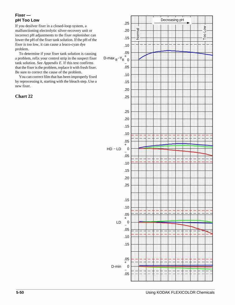
Fixer —pH Too LowIf you desilver fixer in a closed-loop system, amalfunctioning electrolytic silver-recovery unit orincorrect pH adjustments to the fixer replenisher calower the pH of the fixer tank solution. If the pH of thefixer is too low, it can cause a leuco-cyan dyeproblem.
To determine if your fixer tank solution is causinga problem, refix your control strip in the suspect fixertank solution. SeeAppendix E. If this test confirmsthat the fixer is the problem, replace it with fresh fixerBe sure to correct the cause of the problem.
You can correct film that has been improperly fixedby reprocessing it, starting with the bleach step. Usenew fixer.
Chart 22
5-50
n
.
a
Too
Low
Decreasing pH
Nor
mal
HD LD
0
0
+
+.05
.10
.25
.20
.15
.20
.25
.05
.10
.15
.15
.05
.10
.25
.20
0
0
+LD
+D-min
.05
.05
.05
.05
.15
.10
.10
.05
.15
.25
.10
.15
.20
BBD-max Y
Using KODAK FLEXICOLOR Chemicals

er
ue
r
it
thed
es
r
t
ge
t.
f
st
r
s
r
.
,
APPENDIX ARebleaching Test for Retained SilverUse the procedure described below to verify retained-silvproblems.
1. Zero your densitometer. Measure and record the bldensities of the D-max and yellow steps of yourcontrol strip.
2. Rebleach the control strip for 5 minutes in aknowngood bleach(i.e., a properly constituted Process C-41bleach or a solution made from KODAK Farmer’sReducer, Part A).
3. Refix the control strip for 5 minutes in aknown goodfixer (i.e., a properly constituted Process C-41 fixer oa solution made from KODAK Farmer’s Reducer,Part B).
4. Wash the control strip for several minutes and allowto dry.
5. Rezero the densitometer. Read the blue densities ofD-max and yellow steps of the rebleached and refixecontrol strip.
6. Calculate thechangein density readings of the controlstrip by subtracting the readings from step 1 from threadings from step 5. We will refer to these numbers a∆ D-maxB and∆ YB.
7. Subtract∆ D-maxB from ∆ YB to determine theamount of retained silver. If the difference is greatethan + 0.08, a retained-silver problem exists. If thedifference is less than + 0.08, retained silver is moslikely not a problem.
Note: You can remove retained silver from processed filmby following these steps:
1. Rebleach the film in aknown good bleach.
2. Refix the film in aknown good fixer.
3. Run the film through the remaining process steps—wash, final rinse or stabilizer, and dry.
You can also use an infrared scope to detect retainedsilver.
Using KODAK FLEXICOLOR Chemicals
APPENDIX BTest for Bleach StainUse the test described below to determine if your KODAKFLEXICOLOR Bleach III tank solution is producing a stainin processed film. Use a portion of the D-min area of aKODAK Control Strip, Process C-41, that has beenprocessed properly. The portion of the strip should be larenough for you to measure densities in two separatelocations.
To test for bleach stain, follow these steps:
1. Cut a section of D-min from the width of a control stripthat is approximately 13 mm (1⁄2 in.). The D-mindensities should plot in control on your control charIf you do not have a strip that provides in-controlreadings for D-min, use a portion of the D-min area othe reference strip.
2. Remove a sample of the bleach tank solution, andplace it in a small container (e.g., fill a 100 mLgraduate to the 75 mL mark with bleach). Start the tewhen the solution has cooled to room temperature.
3. Insert half of the piece of D-min into the bleachsample. Leave it in the solution for 20 minutes at roomtemperature with no agitation.
4. Immerse the entire D-min film sample in a still-watebath at room temperature for 20 seconds.
5. Allow the film to dry. Read the densities of both halveof the film sample. Compare the density readings. Adifference of more than 0.12 density units in any coloindicates staining from the bleach.
If staining is minimal, an activated carbon filter in therecirculation line of the bleach may help correct the problemIf staining is more severe, replace one third to all of thebleach tank solution. If the tank solution is a regeneratedbleach, replace one third to all of the tank solution, overflowand replenisher solution in your bleach system.
5-51

ed
ntd
r,.
tedd
t
.
.gf
APPENDIX CTest for Proper Bleach AerationUse KODAK Aeration Test Solution to determine if a bleachis sufficiently aerated to be effective. Use the test describbelow with KODAK FLEXICOLOR Bleach III tanksolution.
Materials Needed• KODAK Aeration Test Solution, CAT No. 129 2069
• Eyedropper or pipet
• Vessel for removing a bleach sample
• 10 mL clear glass graduated cylinder or test tube
Procedure
1. Thoroughly stir the bleach solution that you aretesting, and remove a small sample.
2. With an eyedropper or pipet, remove a small amouof the sample, and place one drop of it in the graduatecylinder.
3. Add 5 mL of KODAK Aeration Test Solution to thebleach sample in the graduated cylinder.
4. Swirl the contents of the cylinder until the twosolutions are well mixed.
5. Within 5 minutes of mixing the solutions, note thecolor of the mixed solution in the graduated cylindeand then analyze the results according to Table 5-5
Table 5-5
Note: This test assumes that the bleach solution being tesis at normal concentration; an under- or overconcentratesolution can produce inaccurate test results.
Solution Color Condition
Blue Properly aerated
Green Adequately aerated
Brown Not enough aeration
5-52
APPENDIX DTest for Retained Silver HalideUse this test to determine if processed film has retainedsilver halide.
1. Zero your densitometer. Read and record the redStatus M density of the D-min step of a control stripthat you have processed recently.
2. Refix the control strip for 5 minutes in aknown goodfixer or a solution made from KODAK Farmer’sReducer, Part B.
3. Wash the control strip for 2 to 3 minutes, and allow ito dry.
4. Rezero your densitometer. Read and record the reddensity of the D-min step of the refixed control strip
5. Calculate thechange in density readings bysubtracting the reading from step 4 from the readingfrom step 1.
Any significant change in density readings after refixingindicates a fixer problem. If aloss in red density is greaterthan 0.05 for D-min or LD, a retained silver-halide problemprobably exists due to low activity of the fixer tank solutionThis problem may be accompanied by retained sensitizindye. If thelossin red density is less than 0.04, the activity othe fixer tank solution is probably acceptable.
Using KODAK FLEXICOLOR Chemicals

e
d
it
m
raor
APPENDIX ERebleaching Test for Leuco-Cyan DyeIf the pH of a fixer tank solution is too low, leuco-cyan dymay form. To test for leuco-cyan dye formed in the fixer,follow this procedure:
1. Zero your densitometer. Measure and record the reLD density of a recently processed control strip.
2. Rebleach the control strip for 5 minutes in aknowngood bleach(i.e., a properly constituted Process C-41bleach or a solution made from KODAK Farmer’sReducer, Part A).
3. Wash the control strip for several minutes and allowto dry.
4. Rezero your densitometer. Read the red LD densitythat you measured in step 1.
5. Calculate thechange in density readings bysubtracting the reading from step 1 from the readingfrom step 4. If the difference is greater than +0.08, aleuco-cyan dye problem exists. If the difference isgreater than +0.05, a marginal leuco-cyan dye problemay exist.
6. If the fixer is the source of the problem, dump the fixetank solution and replace it with fresh solution. For closed-loop system, you may add sodium hydroxideammonium hydroxide to the fixer to adjust the pH to6.5± 0.5 (check the pH with a pH meter). Also, checkfor fixer underreplenishment, a current that isexcessive for in-line electrolytic desilvering, orexcessive carryover into the fixer.
Note: You can convert leuco-cyan dye that formed in thefixer to normal cyan dye by following these steps:
1. Rebleach the film in aknown good bleach.
2. Refix the film in aknown good fixer.
3. Run the film through the remaining process steps—wash, final rinse or stabilizer, and dry.
Using KODAK FLEXICOLOR Chemicals
5-53
5-54
Using KODAK FLEXICOLOR Chemicals