process standard digital - typical guidelinesambalaza.hr › userfiles › file › ambalaza ›...
TRANSCRIPT
3/6/2015
1
PROCESS STANDARD DIGITAL – PRINTING
THE EXPECTED
establishing and implementing typical guidelines
Highlights
For later reading
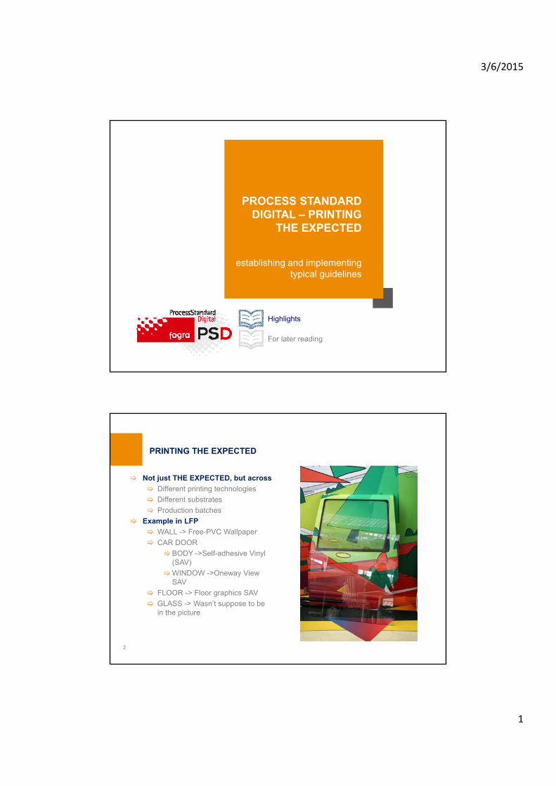
Not just THE EXPECTED, but across
Different printing technologies
Different substrates
Production batches
Example in LFP
WALL -> Free-PVC Wallpaper
CAR DOOR
BODY ->Self-adhesive Vinyl (SAV)
WINDOW ->Oneway View SAV
FLOOR -> Floor graphics SAV
GLASS -> Wasn’t suppose to be in the picture
PRINTING THE EXPECTED
2

3/6/2015
2
PSD guidelines have been published by Fogra in 2012
Online version is free of charge (http://www.fogra.org/en/fogra-fogracert-en/print/processstandard-digital/psd-downloads-e/psd-downloads-en.html)
Digital Printing Working Group (Committee)
Creating, promoting and encouraging the standardization and evolution of vendor neutral digital printing
Discussion and further development
PSD & ISO/TS 15311 – interplay and use case dependent facilitation of the standards
ISO 15311-1 is at CD stage, -2 / -3 (ISO/TS track)
PSD will reflect the ongoing developments ("Living document")
PSD – CODE OF PRACTICE
3
HOW PSD IS ADDRESSING DIGITAL PRINTING NEEDS
4
1. Output Process Control
✔
Large Format
Small Format
2. Colour Fidelity
3. Workflow
✔
✔
⇒ Stability ⇒ Printing the Expected
✔ Data Preflight
✔ PDF/X Creation
✔ PDF/X Output
✔ Altona Test Suite V2
✔ Colour Management
✔ Viewing Conditions
3/6/2015
3
PDF/X is the ideal data exchange format for the printing industry
The purpose of PDF/X is to facilitate graphic content exchange
Specific requirements linked to production workflow needs
PDF/X-4 it is a desirable choice due to its features
Goal: AUTOMATIZATION
PDF/X Profiles
Creation
Preflight
Correction (Fixing)
PDF/X Output
Proper RIP – workflow settings (ex. overprint options)
Your digital file data will output as good as it was created and processed !!!
DATA EXCHANGE WITH PDF/X - PREPARING THE EXPECTED
5
ISO 15930-X
PDF/X standards specifies minimum requirements
Job and / or output specific needs are not covered by the standard scope
Based on graphic industry’s best practices in order to complement the standard and define the much needed parameters
Ghent Working Group – GWG, www.gwg.org
PDF/X-Ready, www.pdfx-ready.ch
Fogra web site
http://www.fogra.org/en/fogra-research/wc-digital-printing/digital-printing-current-projects/consolidating-standardization/research-topics/preflight-check/data-preflight.html
PDF/X “PLUS” PROFILES
6

3/6/2015
4
An aid to determine whether your workflows is behaving in conformance with the PDF/X standards
Ghent PDF Output Suite 4.0
PDFX-ready Output Test v3
Altona Test Test Suite 2 –Technical Page 2
External evaluation and certification of your PDF/X workflow
For data creators
For data processing
PDF/X “PLUS” TESTING
7
The printing condition
Digital press and its printing technology
Colorant
Substrate
Printing mode (LFP)
Tools
Measuring instruments
Measuring protocol
Charts and strips
Profiling application
Validation application
Visual judgment
Standard D50 viewing booth (P1/P2) or light box (T1) as described by ISO 3664:2009
Additional illuminants to evaluate colour metamerism/inconstancy
PRINTING THE EXPECTED = MEASURE AS WE SEE
8
“Where you can measure, there is no need for dispute” –Prof. Dr. Joh. Albrecht, FograNews Nr. 87, P. 2, 1976
3/6/2015
5
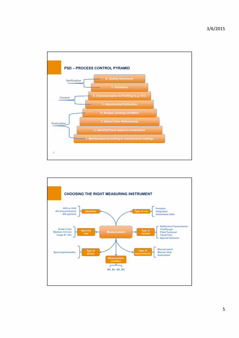
PSD – PROCESS CONTROL PYRAMID
9
WG 2
Prepress data exchange
1. Maintenance according to manufacturer settings
2. Identify/Check material combination
3. Select Color Reference(s)
4. Analyze printing condition
5. Adjustments/Calibration
6. Characterization & Profiling (e.g. ICC)
7. Validation
8. Quality Assurance
Evaluation
Control
Verification
CHOOSING THE RIGHT MEASURING INSTRUMENT
Measurement
Geometry
Aperture size
Type of device
Type of use
Type of sample
Type of measurement
45/0 or 0/45d/0 (transmission)
d/8 (sphere)
Small 2 mmMedium 4-6 mm
Large 8+ mm
Spectrophotometer
PortableIntegratedAutomated table
Reflection/TransmissionFlat/RoughPlain/TexturedThick/ThinSpecial behavior
Manual patchManual stripAutomated
Measurement condition
M0, M1, M2, M3
3/6/2015
6
Data
Spectral whenever possible
No OBA’s or media relative evaluation setup -> M0=M1=M2 by scope
M1 whenever possible, but when using any M standard to exchange data, it is essential to agree on a particular M standard before measuring data
Backing
Mostly measured on white backing
All the printing condition (reference profiles) are generated based on measurements done on white backing
Black backing is viable as an option for measuring special substrates (mesh, one-way view, textiles with lower opacity) due to better visual correlation
Side-by-side comparison between thick and thin substrates
Data quality and consistency
Averaging and smoothing
MEASURING PROTOCOL – BASED ON ISO 13655:2009
11
All measurement devices show random and systematic errors
Such errors can’t be corrected by the user, but they can be detected
Check precision
Short and long term repeatability
Check accuracy
How it agrees with other devices
Periodical measurement of a stable material
Monitor and record the results
A measuring device is only as good as its maintenance status
Preventive maintenance
Recalibration and recertification in due time by manufacturer service
INSTRUMENT PERFORMANCE AND STABILITY
12
3/6/2015
7
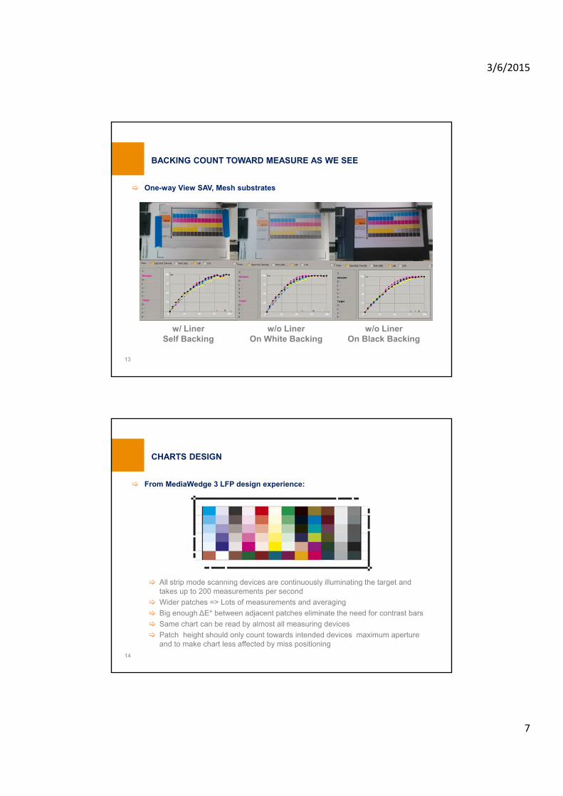
One-way View SAV, Mesh substrates
BACKING COUNT TOWARD MEASURE AS WE SEE
13
w/ LinerSelf Backing
w/o LinerOn White Backing
w/o LinerOn Black Backing
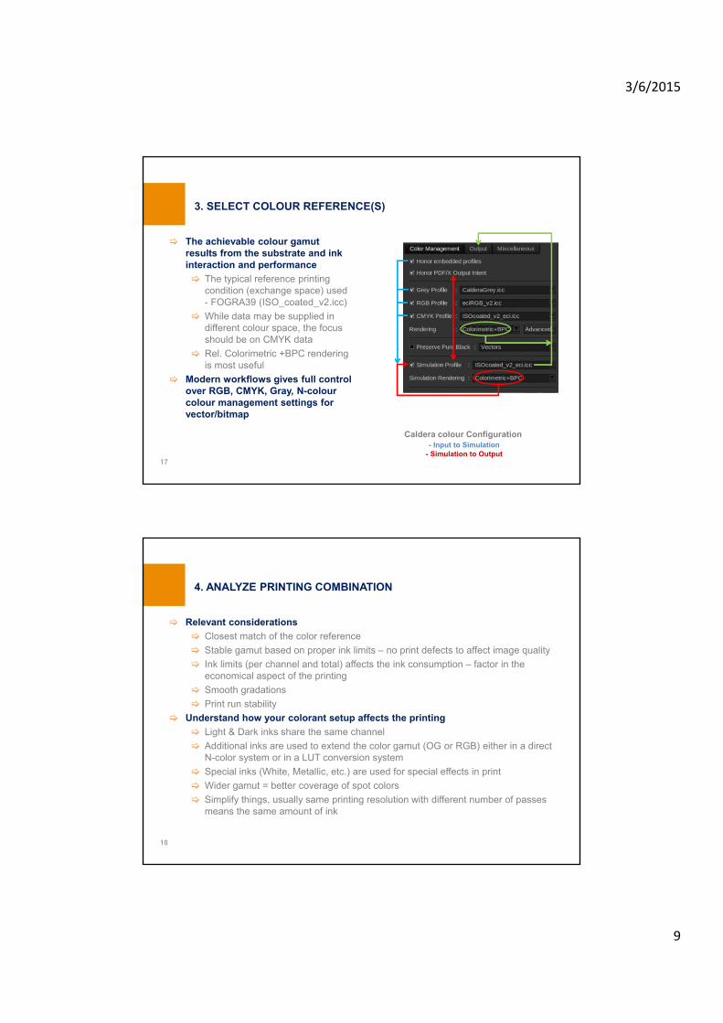
From MediaWedge 3 LFP design experience:
All strip mode scanning devices are continuously illuminating the target and takes up to 200 measurements per second
Wider patches => Lots of measurements and averaging
Big enough ΔE* between adjacent patches eliminate the need for contrast bars
Same chart can be read by almost all measuring devices
Patch height should only count towards intended devices maximum aperture and to make chart less affected by miss positioning
CHARTS DESIGN
14

3/6/2015
8
A printing system is only as good as its maintenance status
Regular service maintenance
Manufacturer periodically recommended operations
Environment conditions of both printing system and substrates used
User operations
LFP
Nozzle status check – certain close range viewing applications are sensitive to missing nozzles
Print heads alignment (in-between and height)
EP
Density control and evenness
Gamma (LUT) adjustments
Color registration
Good knowledge of the printer front panel and functions
If unsure, use default settings as starting point and tweak from there
1. MAINTENANCE AND BASIC SETUP
15
Factor in both printability (testing & setup) and runnability (production)
Select the proper substrates recommended for the used printing technology
Not all substrates are suitable for all printing technologies
Even if printability may be achieved, runnability may be an issue
Choose the desired print mode(s), speed vs. quality (LFP)
Understand specific parameters for Printer (hardware) and Workflow (software)
Set a minimum printability level to qualify a substrate, then push the parameterization to find its limit
Use printer vendor and substrate vendor knowledge base
Simplify things – categorize substrates and their parameters
For drying/curing printing systems, the temperatures applied during pre-printing, printing and post-printing stages are very important for both printability and runnability
2. IDENTIFY AND CHECK MATERIAL COMBINATION
16
3/6/2015
9
The achievable colour gamut results from the substrate and ink interaction and performance
The typical reference printing condition (exchange space) used - FOGRA39 (ISO_coated_v2.icc)
While data may be supplied in different colour space, the focus should be on CMYK data
Rel. Colorimetric +BPC rendering is most useful
Modern workflows gives full control over RGB, CMYK, Gray, N-colour colour management settings for vector/bitmap
3. SELECT COLOUR REFERENCE(S)
17
Caldera colour Configuration- Input to Simulation
- Simulation to Output
Relevant considerations
Closest match of the color reference
Stable gamut based on proper ink limits – no print defects to affect image quality
Ink limits (per channel and total) affects the ink consumption – factor in the economical aspect of the printing
Smooth gradations
Print run stability
Understand how your colorant setup affects the printing
Light & Dark inks share the same channel
Additional inks are used to extend the color gamut (OG or RGB) either in a direct N-color system or in a LUT conversion system
Special inks (White, Metallic, etc.) are used for special effects in print
Wider gamut = better coverage of spot colors
Simplify things, usually same printing resolution with different number of passes means the same amount of ink
4. ANALYZE PRINTING COMBINATION
18

3/6/2015
10
This stage is the first and most important part of the resulting media set
It is foundation on which the ICC color profile will rely and is directly linked to the output quality
Parameters to set
Ink Limit per Channel (LFP)
Obvious physical limit or workflow tool automated suggestion (starting point)
Analogy to offset over and under inking
Linearization
Optimal/defined behavior between paper and solid for each channel by meanings of ISO Status density, spectral density or colorimetrical TVI
Actual linearization may be different from the meaning of the “Linearization”
Total Ink Limit (LFP)
No ink amount behind this value
The process is influenced by the driving RIP workflow, so while the general concept may be applied independently, in particular each workflow may have different approach and tools
5. ADJUSTMENTS/CALIBRATION
19
Use ISO 12642-2 chart IT8.7/4 (random layout preferred) or the Universal LFP based IT8.7/4
From the reference file any custom layout may be generated if necessary
As per any printed chart in the process control, print it repeated over the entire width of the substrate for practical reasons
Automated measuring devices are highly recommended to avoid mistakes and errors (chart contains 1617 patches, 1680 for Universal LFP)
Average with optional interpolation and smoothing
This is your characterization data set for the selected printing combination, basically a fingerprint of your printing system for the chosen parameters
Our printing condition becomes a fully characterized printing condition
6. CHARACTERIZATION & PROFILING
20

3/6/2015
11
PROFILE GENERATION
21
Second stage of the media set based on previously made adjustments and calibration
Any modification on the previous stage requires re-printing and re-measuring of the profiling chart (except re-linearization)
Typical ICC Output Profile will be generated, but Device Link Profile may be also used
Profile generation parameters
May be optimized thru iterative printing and measurement
Lighting
Usual D50
Custom light may be used (e.g. Backlit application)
Separation
Total ink coverage
Black start
Maximum black
Black curve
Black width
Other specific profiler settings
Profile size and quality
Use 16 bit quality
Use Large, more interpolation points = larger profiles
Others
ICC profile version – use v4
Chromatic adaptation – use CIECAT02
PROFILE SETTINGS
22X-Rite i1Profiler
3/6/2015
12
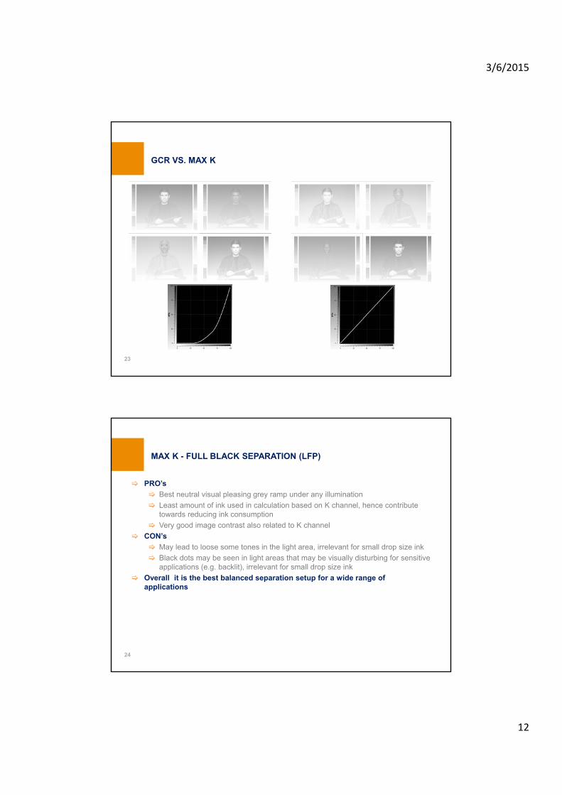
GCR VS. MAX K
23
PRO’s
Best neutral visual pleasing grey ramp under any illumination
Least amount of ink used in calculation based on K channel, hence contribute towards reducing ink consumption
Very good image contrast also related to K channel
CON’s
May lead to loose some tones in the light area, irrelevant for small drop size ink
Black dots may be seen in light areas that may be visually disturbing for sensitive applications (e.g. backlit), irrelevant for small drop size ink
Overall it is the best balanced separation setup for a wide range of applications
MAX K - FULL BLACK SEPARATION (LFP)
24
3/6/2015
13
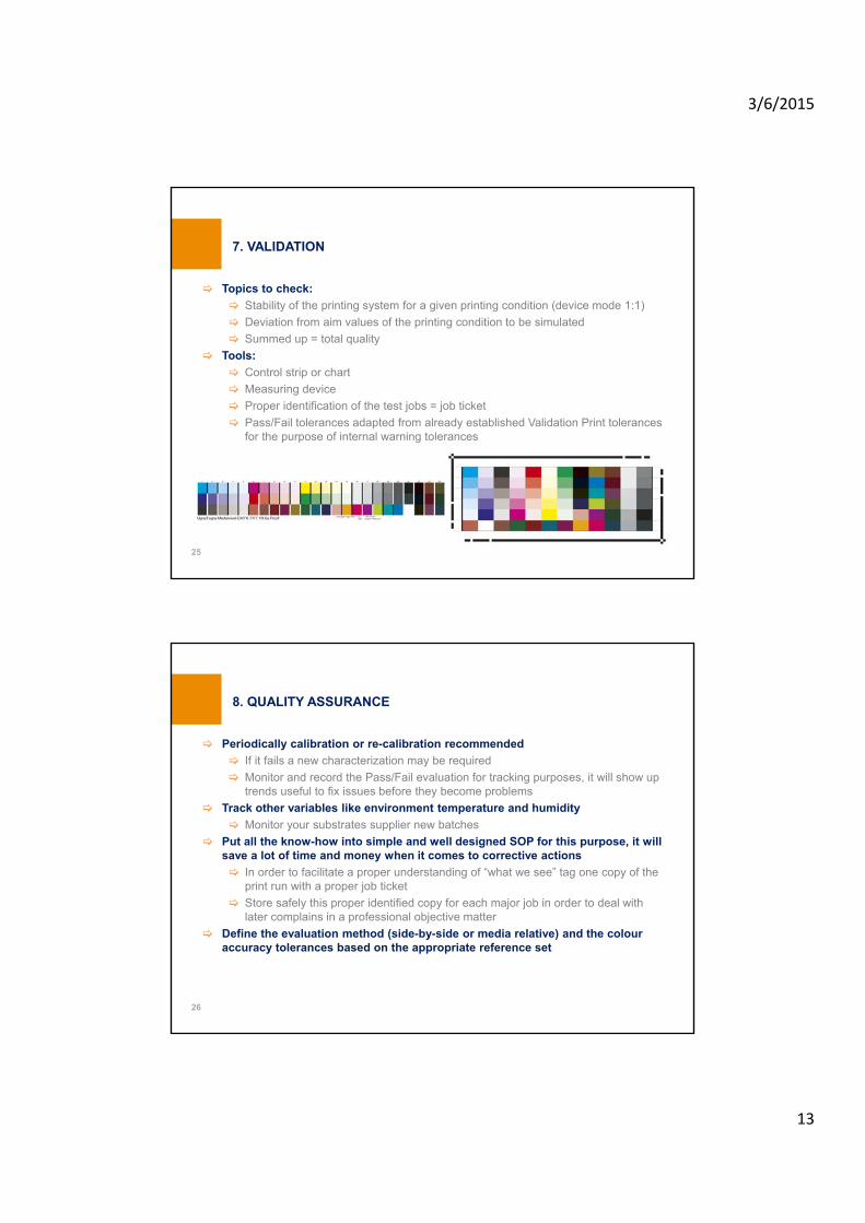
Topics to check:
Stability of the printing system for a given printing condition (device mode 1:1)
Deviation from aim values of the printing condition to be simulated
Summed up = total quality
Tools:
Control strip or chart
Measuring device
Proper identification of the test jobs = job ticket
Pass/Fail tolerances adapted from already established Validation Print tolerances for the purpose of internal warning tolerances
7. VALIDATION
25
Periodically calibration or re-calibration recommended
If it fails a new characterization may be required
Monitor and record the Pass/Fail evaluation for tracking purposes, it will show up trends useful to fix issues before they become problems
Track other variables like environment temperature and humidity
Monitor your substrates supplier new batches
Put all the know-how into simple and well designed SOP for this purpose, it will save a lot of time and money when it comes to corrective actions
In order to facilitate a proper understanding of “what we see” tag one copy of the print run with a proper job ticket
Store safely this proper identified copy for each major job in order to deal with later complains in a professional objective matter
Define the evaluation method (side-by-side or media relative) and the colour accuracy tolerances based on the appropriate reference set
8. QUALITY ASSURANCE
26
3/6/2015
14
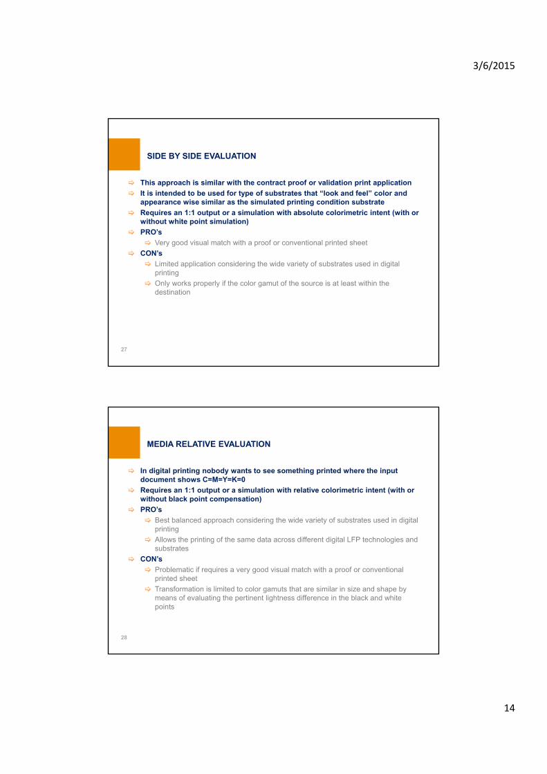
This approach is similar with the contract proof or validation print application
It is intended to be used for type of substrates that “look and feel” color and appearance wise similar as the simulated printing condition substrate
Requires an 1:1 output or a simulation with absolute colorimetric intent (with or without white point simulation)
PRO’s
Very good visual match with a proof or conventional printed sheet
CON’s
Limited application considering the wide variety of substrates used in digital printing
Only works properly if the color gamut of the source is at least within the destination
SIDE BY SIDE EVALUATION
27
In digital printing nobody wants to see something printed where the input document shows C=M=Y=K=0
Requires an 1:1 output or a simulation with relative colorimetric intent (with or without black point compensation)
PRO’s
Best balanced approach considering the wide variety of substrates used in digital printing
Allows the printing of the same data across different digital LFP technologies and substrates
CON’s
Problematic if requires a very good visual match with a proof or conventional printed sheet
Transformation is limited to color gamuts that are similar in size and shape by means of evaluating the pertinent lightness difference in the black and white points
MEDIA RELATIVE EVALUATION
28

3/6/2015
15
REPORTING PROTOCOL
29
Print created by: Dorin Pitigoi Date: 07.01.13 / 18:04
Last calibration: 20.07.12 Workflow: Caldera v9
Measuring device: X-Rite i1Pro2 Measuring conditions: 45/0, D50, 2, M0, WB
Printing condition: FOGRA39 Reference profile: ISOcoated_v2.icc
Printer: HP Designjet L26500 Colorant: HP Latex Inks HP 792
Substrate: HP Photo-realistic Poster Paper Output profile: Designjet-L26500_HPPRPPHP2_600_CMYKcm_12pB.icc
Printing mode: CMYKcm 600 12-pass-Bi Intent: Absolute colorimetric
∆E*ab ∆E*00 Actual Actual1,0 1,0 OK OK2,0 1,0 OK OK7,0 5,0 not OK OK3,1 2,3 OK2,8 not OK0,8 OK1,1 OK3,0 OK
Hue difference ∆H (average gray)Chromaticness difference ∆Ch (average gray)
ISO 12647-8 [VPC]Measured
Paper White (max.)All patches (average)All patches (max.)Primary colors (max.)Hue difference ∆H (max. CMYK)
Hue difference ∆H (max. CMYRGB)
ISO 12647-7 [CPC]
PASSED
Tolerance
1,52,5563
Tolerance3
42,5
833
FAILED
∆E*ab ∆E*00 Actual ActualA B C A B C
1,0 1,0 2 3 4 A2,0 1,0 2 3 4 A 1,5 2,5 4 A7,0 5,0 6 7 8 A 5 7 10 A3,1 2,32,8 -0,8 -1,1 - 2,5 3,5 4,5 A3,0 - 4 5 6 A
Paper White (max.)All patches (average)
Measured ISO 15311 Side-by-Side [PSD] ISO 15311 Media Relative [PSD]
Chromaticness difference ∆Ch (average gray)Hue difference ∆H (max. CMYRGB)
Hue difference ∆H (max. CMYK)Hue difference ∆H (average gray)
All patches (max.)Primary colors (max.)
PASSED QUALITY A PASSED QUALITY A
Tolerance Tolerance
Minimum quality level rules
Spot colours are used mostly as solids, compared to tone values or overprints with other colors
Sources
Spot colours libraries – make sure that there is consistency between the file reference and the available library (example 364 C, Pantone vs. Pantone+)
Physical sample thru measurement – same considerations as any measurement
Digital file container consisting of physical aspects and specific information of the colour – CxF/3, CxF/X
With the addition of CxF/X-4 complete characterisation (solid, tones, opacity) allows reliable printing and proofing of products designed using spot colour inks
How to print The Expected
Unambiguous communication of colour specification and tight measurement protocol
Accurate characterization of the output printing condition
Check if in-gamut colour and tweak either the reference (media dependent reference) or the output mapping (media dependent CMYK+ recipe) for a best match (smallest ΔE*00) colour reproduction for a given printing condition
SPOT COLOURS HANDLING
30

3/6/2015
16
The best viewing condition for the visual assessment of colour is that in which the product will be finally seen, but such an opportunity is very rare
For critical purpose of colour comparison and appraisal, an ISO 3664:2009 compliant viewing booth/illuminaire shall be used
From other industries best practices, additional illuminants should be used for informative checking of metamerism and inconstancy
VISUAL COMPARISON AND APPRAISAL
31Metamerism
Inconstancy Inconstancy
Daylight
Tungsten
Fluorescent
POS/POP production using conventional (screen) and digital (LFP) printing technologies
Scope of the project
Brand colour matching between conventional (spot colour) and digital printing (process CMYK) not only under D50, but also A and TL84 on various substrates
Tools
iCQ and eXact for standard definition and Pass/Fail analysis
i1Profiler and i1Pro2/iO2 for advanced profiling and optimization of digital printing conditions
Achievements
Dependent standards definition for various digital printing conditions
Max 2,5 ΔE*00 difference between Master Standard reproduction (screen) and Dependent Standard reproduction (digital) under any of the 3 illuminants checked
PSD IN PRACTICE – HYBRID WORKFLOW (ACTUAL CASE)
32

3/6/2015
17
Print on demand interior decoration using digital (LFP) printing technologies on wallpaper, SAV and Canvas
Scope of the project
Reduce ink consumption, increase colour accuracy (reproduction quality) and colour consistency (day-to-day, press-to-press)
Tools
i1Profiler and i1 iSis for advanced profiling and optimization of digital printing conditions, built-in HP spectrophotometer for process control
i1Pro2 and 3rd party tool for QA check of PSD quality levels conformance
Achievements
3% to 19% ink usage reduction dependent on the substrate used due to excellent MaxK profiling generation provided by i1Profiler
Colour accuracy level increased by one level (from B to A on SAV and Canvas, from C to B on wallpaper, ABC based Fogra PSD evaluation)
Average 1,5 ΔE*00 colour consistency between runs and presses (sampling)
Bonus: productivity increase due to faster printing speed possibility
PSD IN PRACTICE – LFP WORKFLOW (ACTUAL CASE)
33
PSD concept correctly implemented as industrial procedure works very nicely for any application
Applications produced in hybrid workflows (mixture of conventional and/or digital printing technologies) - printing the expected
Digital produced applications are no longer limited only to traditional applications – garments textile and interior decorations
Spot color reproduction requires similar level of quality control as already established color critical reproduction applications
Demonstrate that you understand customer expectations
Improve colour communication throughout the production chain
Implement objective means for your process control and quality assurance
APPLYING PSD IN BRIEF
34

3/6/2015
18
Thank you for your attentionQ & A
Dorin Pitigoicolour & standardization expert
Expert and head of Romanian delegation at ISO TC 130 (Graphic Technology)Contributor to WG 2 (Prepress data exchange), WG 3 (Process control and related metrology), WG 13 (Printing Conformity Assessment Requirements), TF 3 (Workflow standards roadmap), JWG 14
(Print quality measurement methods)
Current editor of ISO/TS 15311-3, Graphic Technology - Requirements for printed matter utilizing digital printing technologies for the commercial and industrial production – Part 3: Large Format
Signage Printing
FOGRA PSO QUALIFIED PARTNER & DIGITAL PRINT EXPERTUGRA CERTIFIED EXPERT
35