process valve specialists - norflo
TRANSCRIPT

Process Valve Specialists for the Offshore, Marine and Industrial sectors
NORFLO.NO
NORFLO VALVE SELECTION GUIDE
2
NOrflO ValVe SelectION GUIDe
3
AbOUT NORFLO
Norflo is a leading supplier of process valve solutions for the Norwegian and international markets. Since the company was founded in 2003, our team of experts has gained a wealth of knowledge and experience in developing solutions for the offshore oil industry, as well as the marine and industrial sectors.
AbOUT ThIS GUIDE
The extensive range of available valves and solutions can make the valve selection process daunting and time consuming. At Norflo, we pride ourselves on helping our customers to select the correct valve to meet their process requirements. We have therefore compiled this selection guide to give our customers an accessible overview of our products and solutions. We hope that this will not only provide procurement personnel with an easy to use source of essential information, but that the technical data contained within these pages will also make this guide a valuable reference for technical staff.
YOUR PARTNER IN VALVES AND CONTROLS
We are passionate about delivering top quality valves and valve accessories along with excellent customer service at all stages of the sales process. Identification of any potential issues, fast delivery of documentation and ensuring your products are delivered on time are all part of our personal, flexible service.Our process valve specialists are always available to answer your questions or to provide a competetive free quotation for your next project, so please don’t hesitate to get in touch by telephone at +47 51 60 56 30, or e-mail at [email protected]. You can also find more information on our website, www.norflo.no. Thank you for your interest in Norflo – we hope you will find this guide useful, and look forward to hearing from you!
Best wishes,
Svein Svensen
Managing Director, Norflo aS
Norflo AS
Varabergmyra 4-8
4050 Sola
Norway
Tel: +47 51 60 56 30
E-mail: [email protected]
Web: www.norflo.no
Welcome to
the Norflo
Valve Selection Guide
INDeX
03 iNTro
WelcometotheNorfloValveSelectionGuide
04 VAlVE chEck liST
Toensureyouhaveconsideredallrelevantfactors
06 VAlVE producTS
Ballvalves
Gatevalves
Globevalve
Checkvalves
Doubleblock&bleedvalves
Butterflyvalves
Actuators
Accessories
09 VAlVES for iNduSTry ANd
ThE offShorE ANd mAriNE SEcTorS
Seteventil/Globevalve
Nåleventiler/Needlevalve
Tilbakeslagsventiler/Checkvalve
Stormklaffventiler/Stormflapvalve
Kuleventiler/Ballvalve
Sluseventiler/Gatevalve
Skjyvespjeldventiler/Knifegatevalve
Spjeldventiler/Butterflyvalve
Trykkreduksjonsventiler/Pressurereducingvalve
Stengbartilbakeslagsventiler/Screwdown
non-return/SDNR
Y-filter/Y-strainer
Grovfilter/Mudbox
Diverseventilerogutstyr/Othervalvesandaccessories
13 VAlVE dATA ANd mEASurEmENTS
14 BAll VAlVE
Trunnionmounted,splitbody,endentry,fullbore
14 BAll VAlVE
Trunnionmounted,splitbody,endentry,reducedbore
BAll VAlVE
Floatingball,splitbody,endentry,fullandreducedbore
19 chEck VAlVE
Dualplatewafercheckvalve,flangedends
chEck VAlVE
API6Adualplatewafercheckvalve,flangedends
chEck VAlVE
Dualplatewafercheckvalve,buttweldends
chEck VAlVE
Swingcheckvalve
23 GATE VAlVE
Boltedbonnet,standardandreducedbore,OS&Y
GATE VAlVE
Boltedbonnet-reducedbore,OS&Y
GATE VAlVE
Pressureseal,OS&Y
GATE VAlVE
Boltetbonnet,OS&Y,solidorflexiblewedge
26 GloBE VAlVE
Boltedbonnet,fullbore,OS&Y
GloBE VAlVE
Boltedbonnet,reducedbore,OS&Y
GloBE VAlVE
Weldedbonnet,fullbore,OS&Y
GloBE VAlVE
Weldedbonnet,reducedbore,OS&Y
GloBE VAlVE
Boltedbonnet,OS&Yswiveldisc
29 BuTTErfly VAlVE
Softseatwaferbutterflyvalve
BuTTErfly VAlVE
Softseatlugbutterflyvalve
BuTTErfly VAlVE
Highperformancedoubleoffsetbutterflyvalve
BuTTErfly VAlVE
Highperformancetripleoffset,metalseated
butterflyvalve
31 mATEriAl SpEcificATioNS
32 VAlVE BolTiNGS
33 ENd iNfo
34 GASkET SElEcTioN
34 flANGE dimENSioNS
37 ApplicABlE STANdArdS
4 5
NOrflO ValVe SelectION GUIDe
FUNCTION
WHAT IS THE PURPOSE OF THE VALVE?
WHAT FUNCTION IS REQUIRED?• Starting and stopping the flow
• regulating (throttling) the flow
• Preventing reversal of the flow
• regulating or relieving the pressure of the flow
WHAT TYPE OF VALVE IS NEEDED TO MEET THE
FLOW REQUIREMENT? • Ball valve
• Butterfly valve
• combination valve
• check valve
• Globe valve
• Gate valve
• Needle valve
• Plug valve
• control valve
• Other valve types
SERVICE CONSIDERATIONS
WHAT PHYSICAL CONDITIONS WILL
THE VALVE HAVE TO ENDURE?
1. PRESSUREHOW DEMANDING ARE THE PRESSURE CONDITIONS?WHAT PRESSURE RATING IS NEEDED
FOR THE VALVE?• aNSI class 150# - 4500#
• aPI class 2000 PSI - 15000 PSI
• DIN class PN6 - PN414
• JIS class 5K - 40K
2. TEMPERATURE/TYPE OF SERVICE
WHAT ARE THE SERVICE CONDITIONS?• liquid/gas/dirty or abrasive (erosive) or corrosive fluid
• What is the design/service temperature?
• Other
WHAT MATERIAL SHOULD BE USED
FOR THE SERVICE?• Ductile iron
• Nodular cast iron
• carbon steel
• Stainless steel
• Duplex/S duplex
• 6 mo
• titanium
• Other
ValVe cHecK lISt
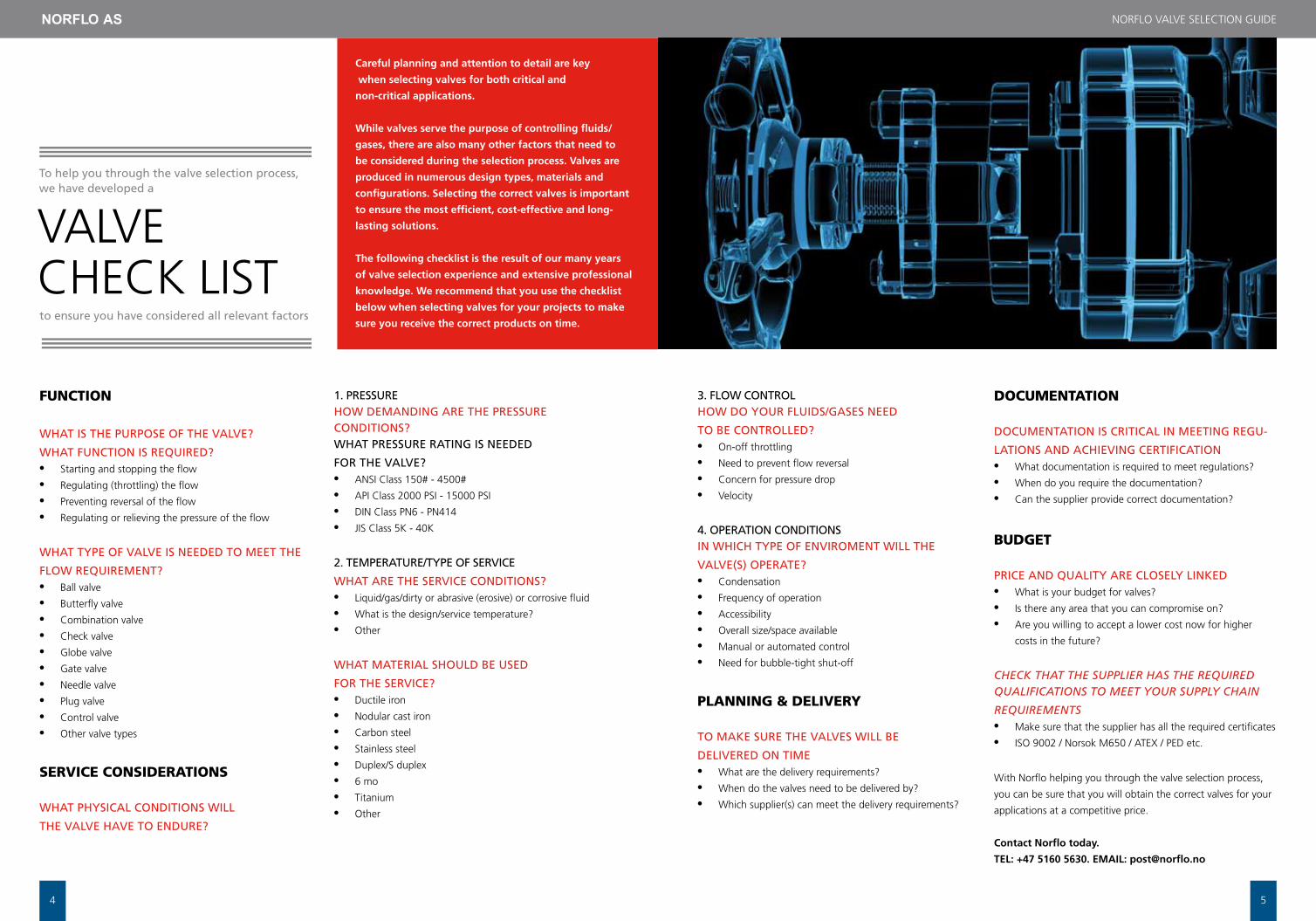
careful planning and attention to detail are key
when selecting valves for both critical and
non-critical applications.
While valves serve the purpose of controlling fluids/
gases, there are also many other factors that need to
be considered during the selection process. Valves are
produced in numerous design types, materials and
configurations. Selecting the correct valves is important
to ensure the most efficient, cost-effective and long-
lasting solutions.
The following checklist is the result of our many years
of valve selection experience and extensive professional
knowledge. We recommend that you use the checklist
below when selecting valves for your projects to make
sure you receive the correct products on time.
To help you through the valve selection process, we have developed a
to ensure you have considered all relevant factors
3. FLOW CONTROLHOW DO YOUR FLUIDS/GASES NEED
TO BE CONTROLLED?• On-off throttling
• Need to prevent flow reversal
• concern for pressure drop
• Velocity
4. OPERATION CONDITIONSIN WHICH TYPE OF ENVIROMENT WILL THE
VALVE(S) OPERATE?• condensation
• frequency of operation
• accessibility
• Overall size/space available
• Manual or automated control
• Need for bubble-tight shut-off
PLANNING & DELIVERY
TO MAKE SURE THE VALVES WILL BE
DELIVERED ON TIME• What are the delivery requirements?
• When do the valves need to be delivered by?
• Which supplier(s) can meet the delivery requirements?
DOCUMENTATION
DOCUMENTATION IS CRITICAL IN MEETING REGU-
LATIONS AND ACHIEVING CERTIFICATION• What documentation is required to meet regulations?
• When do you require the documentation?
• can the supplier provide correct documentation?
bUDGET
PRICE AND QUALITY ARE CLOSELY LINKED• What is your budget for valves?
• Is there any area that you can compromise on?
• are you willing to accept a lower cost now for higher
costs in the future?
CHECK THAT THE SUPPLIER HAS THE REQUIRED QUALIFICATIONS TO MEET YOUR SUPPLY CHAIN
REQUIREMENTS• Make sure that the supplier has all the required certificates
• ISO 9002 / Norsok M650 / ateX / PeD etc.
With Norflo helping you through the valve selection process,
you can be sure that you will obtain the correct valves for your
applications at a competitive price.
contact Norflo today.
TEl: +47 5160 5630. EmAil: [email protected]
6
NOrflO ValVe SelectION GUIDe
7
ValVePrODUctS
Ball valves
Gate valves
Globe valves
Check valves
Double block & bleed valves
Butterfly valves
Actuators
Accessories
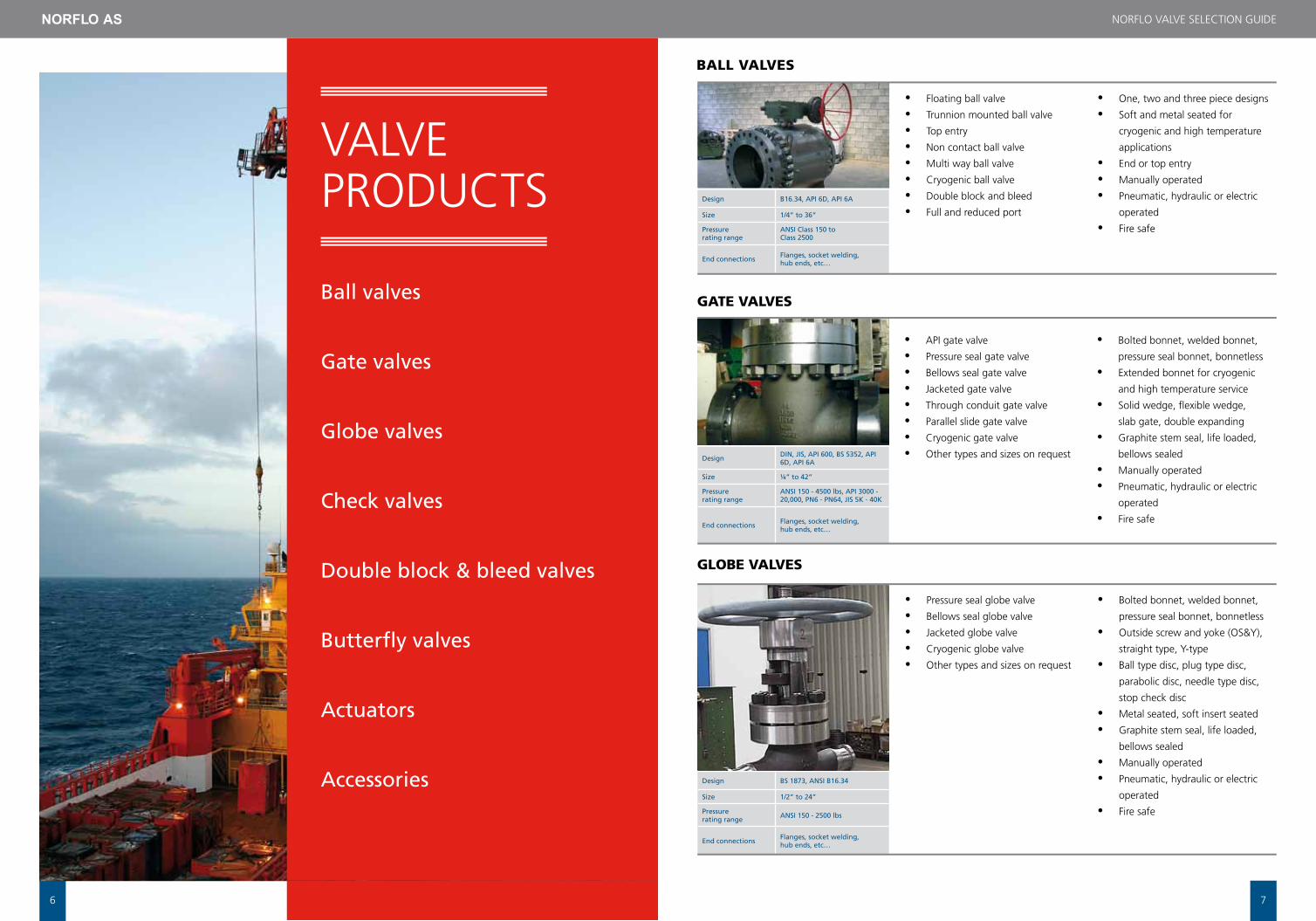
Design B16.34, API 6D, API 6A
Size 1/4” to 36”
Pressure rating range
ANSI Class 150 to Class 2500
End connections Flanges, socket welding, hub ends, etc…
Design DIN, JIS, API 600, BS 5352, API 6D, API 6A
Size ¼” to 42”
Pressure rating range
ANSI 150 - 4500 lbs, API 3000 - 20,000, PN6 - PN64, JIS 5K - 40K
End connections Flanges, socket welding, hub ends, etc…
Design BS 1873, ANSI B16.34
Size 1/2” to 24”
Pressure rating range ANSI 150 - 2500 lbs
End connections Flanges, socket welding, hub ends, etc…
• floating ball valve
• trunnion mounted ball valve
• top entry
• Non contact ball valve
• Multi way ball valve
• cryogenic ball valve
• Double block and bleed
• full and reduced port
• One, two and three piece designs
• Soft and metal seated for
cryogenic and high temperature
applications
• end or top entry
• Manually operated
• Pneumatic, hydraulic or electric
operated
• fire safe
• aPI gate valve
• Pressure seal gate valve
• Bellows seal gate valve
• Jacketed gate valve
• through conduit gate valve
• Parallel slide gate valve
• cryogenic gate valve
• Other types and sizes on request
• Bolted bonnet, welded bonnet,
pressure seal bonnet, bonnetless
• extended bonnet for cryogenic
and high temperature service
• Solid wedge, flexible wedge,
slab gate, double expanding
• Graphite stem seal, life loaded,
bellows sealed
• Manually operated
• Pneumatic, hydraulic or electric
operated
• fire safe
• Pressure seal globe valve
• Bellows seal globe valve
• Jacketed globe valve
• cryogenic globe valve
• Other types and sizes on request
• Bolted bonnet, welded bonnet,
pressure seal bonnet, bonnetless
• Outside screw and yoke (OS&Y),
straight type, Y-type
• Ball type disc, plug type disc,
parabolic disc, needle type disc,
stop check disc
• Metal seated, soft insert seated
• Graphite stem seal, life loaded,
bellows sealed
• Manually operated
• Pneumatic, hydraulic or electric
operated
• fire safe
bALL VALVES
GATE VALVES
GLObE VALVES
8
NOrflO ValVe SelectION GUIDe
9
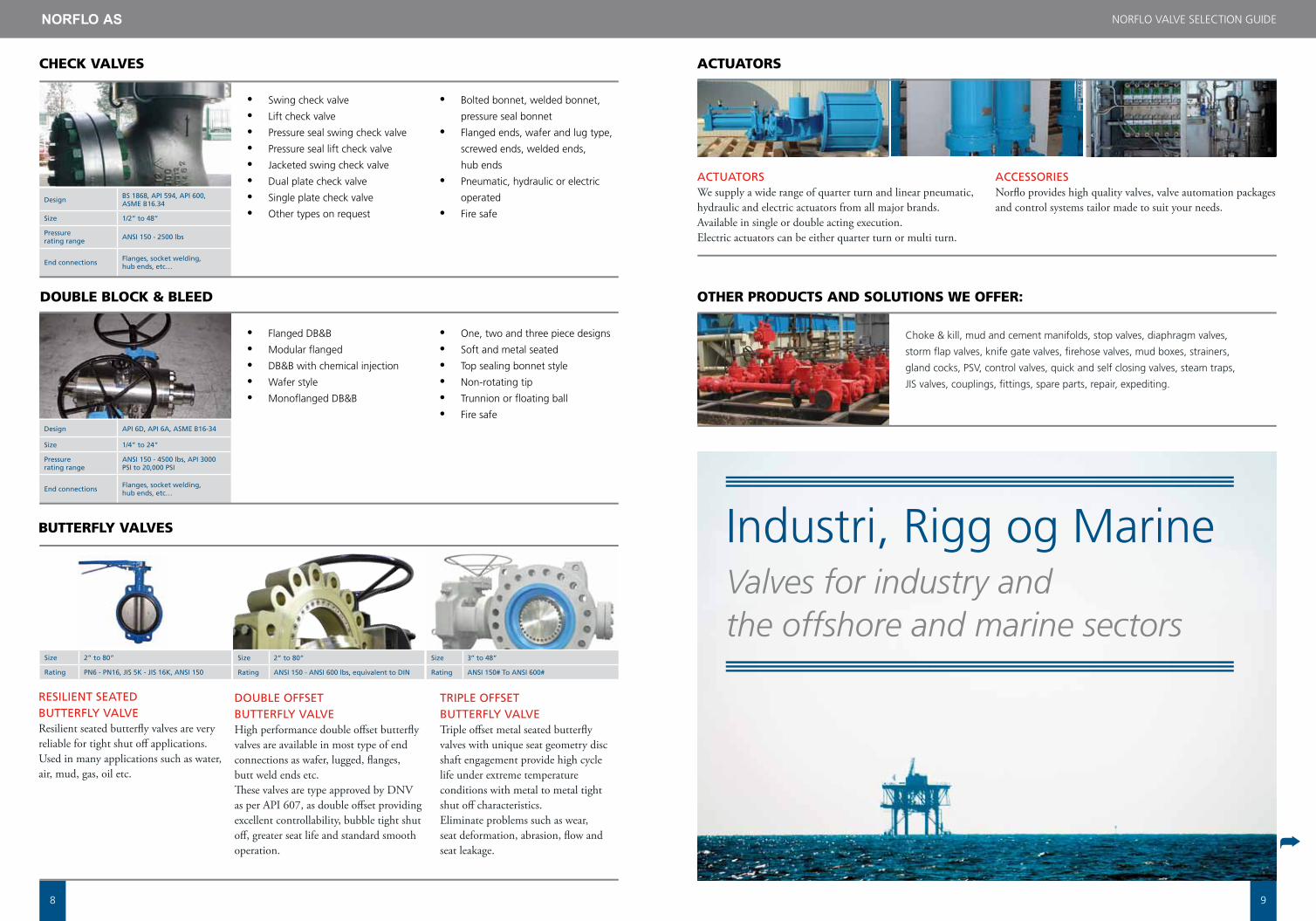
Design BS 1868, API 594, API 600, ASME B16.34
Size 1/2” to 48”
Pressure rating range ANSI 150 - 2500 lbs
End connections Flanges, socket welding, hub ends, etc…
Design API 6D, API 6A, ASME B16-34
Size 1/4” to 24”
Pressure rating range
ANSI 150 - 4500 lbs, API 3000 PSI to 20,000 PSI
End connections Flanges, socket welding, hub ends, etc…
• Swing check valve
• lift check valve
• Pressure seal swing check valve
• Pressure seal lift check valve
• Jacketed swing check valve
• Dual plate check valve
• Single plate check valve
• Other types on request
• Bolted bonnet, welded bonnet,
pressure seal bonnet
• flanged ends, wafer and lug type,
screwed ends, welded ends,
hub ends
• Pneumatic, hydraulic or electric
operated
• fire safe
• flanged DB&B
• Modular flanged
• DB&B with chemical injection
• Wafer style
• Monoflanged DB&B
• One, two and three piece designs
• Soft and metal seated
• top sealing bonnet style
• Non-rotating tip
• trunnion or floating ball
• fire safe
ChECK VALVES
DOUbLE bLOCK & bLEED
Size 2” to 80”
Rating PN6 - PN16, JIS 5K - JIS 16K, ANSI 150
RESILIENT SEATED BUTTERFLY VALVEResilient seated butterfly valves are very reliable for tight shut off applications.Used in many applications such as water, air, mud, gas, oil etc.
bUTTERFLY VALVES
Size 2” to 80”
Rating ANSI 150 - ANSI 600 lbs, equivalent to DIN
DOUBLE OFFSET BUTTERFLY VALVEHigh performance double offset butterfly valves are available in most type of end connections as wafer, lugged, flanges, butt weld ends etc. These valves are type approved by DNV as per API 607, as double offset providing excellent controllability, bubble tight shut off, greater seat life and standard smooth operation.
Size 3’’ to 48”
Rating ANSI 150# To ANSI 600#
TRIPLE OFFSET BUTTERFLY VALVETriple offset metal seated butterfly valves with unique seat geometry disc shaft engagement provide high cycle life under extreme temperature conditions with metal to metal tight shut off characteristics.Eliminate problems such as wear, seat deformation, abrasion, flow and seat leakage.
choke & kill, mud and cement manifolds, stop valves, diaphragm valves,
storm flap valves, knife gate valves, firehose valves, mud boxes, strainers,
gland cocks, PSV, control valves, quick and self closing valves, steam traps,
JIS valves, couplings, fittings, spare parts, repair, expediting.
ACTUATORS We supply a wide range of quarter turn and linear pneumatic, hydraulic and electric actuators from all major brands. Available in single or double acting execution.Electric actuators can be either quarter turn or multi turn.
ACCESSORIESNorflo provides high quality valves, valve automation packages and control systems tailor made to suit your needs.
ACTUATORS
OThER PRODUCTS AND SOLUTIONS wE OFFER:
Industri, rigg og MarineValves for industry and the offshore and marine sectors
➦

10
NOrflO ValVe SelectION GUIDe
11
Dimensjoner DN8 - DN 350
Trykklasse PN 4, PN 40, PN63, JIS 5K, 10K, 16K, ANSI 150 lbs, ANSI 300 lbs
Anslutnings valg Flens, gjenger, BW, SW
SETE VENTIL GlOBe ValVe
DIMENSJONER / DIMENSIONS: DN8 - DN 350 TRYKKLASSE / PRESSURE RATING: PN 4, PN 40, PN63, JIS 5K, 10K, 16K, ANSI 150 lbs, ANSI 300 lbs. ANSLUTNINGS VALG / SOCKET: Flens (flange), gjenger (treads), BW, SWFUNKSJON OG KONSTRUKSJONER: Rett løp eller vinkel seteventil, parabolsk kjegle, myk tettende sete i skråstilling, metalltettende sete, gjenget overdel med låsemutter, ettertrekking av pakkboks, boltet overdel. FEATURES: Straight or angle pattern, parabolic disc, soft seat, metal seat, threaded secured bonnet, adjustable gland packing, bolted bonnet.ANVENDELSESOMRåDER: luft, olje, damp, sjøvann, ferskvann. APPLICATIONS: Air, oil, steam, seawater, freshwater. MATERIALVALG: Bronse, messing, støpejern, seigjern, støpestål, rustfrittMATERIALS: Gunmetal, brass, cast iron, ductile iron, stainless steel.
DIMENSJONER / DIMENSIONS: DN 8 - DN 15 TRYKKLASSE / PRESSURE RATING: PN 100 - PN 400ANSLUTNINGS VALG / SOCKET: BSP, NPT
FUNKSJON OG KONSTRUKSJONER: For høyt trykk og for regulering.FEATURES: For high pressure and manual control.ANVENDELSESOMRåDER: Luft, sjøvann, ferskvann, oljeAPPLICATIONS: Air, seawater, freshwater, oil MATERIALVALG: Messing, rustfritt MATERIALS: Brass, stainless steel
Dimensjoner DN 8 - DN 15
Trykklasse PN 100 - PN 400
Anslutnings valg BSP eller NPT
NåLEVENTILER NeeDle ValVe
DIMENSJONER / DIMENSIONS: DN 8 - DN 350
TRYKKLASSE / PRESSURE RATING: PN 6 - PN 40
ANSLUTNINGS VALG / SOCKET: Monteres mellom flenser (mount between flanges): ANSI, DIN, JISFUNKSJON OG KONSTRUKSJONSMULIGHETER: Konstruert for å forhindre tilbakestrømning av mediet. Kan fås som enkel eller dobbel klaff, myk eller metalltettende sete. Kan utstyres med fjær for hindring av “klapping”. FEATURES: Constructed to prevent back flow. Can be delivered as single or double disc, soft or metal seat. Can also be equipped with spring to prevent “chatter” in the pipe.ANVENDELSESOMRåDER: Luft, sjøvann, ferskvann, kjemikalier, gass, damp, oljer.APPLICATIONS: Air, seawater, freshwater, oil, gas, petrochemicals, steam.MATERIALVALG: Galv. stål, støpejern, seigjern, aluminium bronse, bronse, rustfritt, MATERIALS: Steel, cast iron, ductile iron, alum. bronze, bronze, stainless steel.
Dimensjoner DN 8 - DN 350
Trykklasse PN 6 - PN 40
Anslutnings valg Monteres mellom flenser; ANSI, DIN, JIS
TILbAKESLAGSVENTILER cHecK ValVe
Dimensjoner DN15 - DN 150
Trykklasse PN 4, boret flens til (drilled to) PN 10
Anslutnings valg Flens; DIN, JIS, ANSI
STORMKLAFF VENTIL StOrM flaP ValVe
DIMENSJONER / DIMENSIONS: DN15 - DN 150
TRYKKLASSE/ PRESSURE RATING: PN 4, boret flens til (drilled to) PN 10ANSLUTNINGS VALG / SOCKET: Flens (flange): DIN, JIS, ANSI FUNKSJON OG KONSTRUKSJONSMULIGHETER: Konstruert for å hinde sjøvann slår tilbake inn i rørsystemer. Kan fåes med manuel overstyring for hurtig stengning. FEATURES: Designed to prevent “back flow” and avoid sea water coming back into pipe system. Can be delivered with manual override for fast shutdown. ANVENDELSESOMRåDER / APPLICATION: Sjøvann (Seawater)
MATERIALVALG / MATERIALS: Seigjern, støpejern, bronse (Ductile iron, cast iron, bronze)
Dimensjoner DN 8 - DN 500
Trykklasse 2 - 40 bar, PN 4 - PN 170
Anslutnings valg BSP, NPT, BW. Flens (flange): ANSI, DIN, JIS
KULEVENTIL Ball ValVe
DIMENSJONER / DIMENSIONS: DN 8 - DN 500. TRYKKLASSE / PRESSURE RATING: 2 - 40 bar, PN 4 - PN 170. ANSLUTNINGS VALG / SOCKET: BSP, NPT, BW.
Flens (flange): ANSI, DIN, JIS. FUNKSJON OG KONSTRUKSJONSMULIGHETER: Helsveist, to eller tredelt kuleventil, dreneringsplugg, utblåsningssikker spindel, fullt eller redusert
gjennomløp, flyende eller opplagret kule, ISO 5211 toppflens for aktuator montasje. Kan fås med
høy spindelhals for isolering. FEATURES: Fully welded, two or three piece ball valve, bleeder plug,
anti blow-out proof stem, full or reduced bore, floating or trunnion mounted ball, ISO 5211 top flange
for actuator. Stem extension for isolation. ANVENDELSESOMRåDER: Drikkevann, sjøvann,
damp, luft, gasser, petroleumsprodukter. APPLICATIONS: Drinking water, seawater, steam, air, gas,
petrochemicals. MATERIALVALG: Messing, rustfritt, støpejern, seigjern, rødmetall, WCB, stål.
MATERIALS: Brass, stainless steel, cast iron, ductile iron, gunmetal, carbon steel, steel.
Dimensjoner DN 40 - DN 600
Trykklasse PN 4 - PN 100
Anslutnings valg Flens; DIN, JIS, ANSI. SW, BW.
SLUSEVENTIL Gate ValVe
DIMENSJONER / DIMENSIONS: DN 40 - DN 600 TRYKKLASSE / PRESSURE RATING: PN 4 - PN 100 ANSLUTNINGS VALG / SOCKET: SW, BW. Flens (flange): DIN, JIS, ANSI.FUNKSJON OG KONSTRUKSJONSMULIGHETER: Innvendig gjenget spindel med mulighet for ettertrekking av pakkboks. Kan fås med “ikke stigende spindel” men som OS&Y (outside screw & yoke) som er beregnet for åpning og stengning av flytende medium.FEATURES: Internally threaded stem, with option to adjust gland packing. Can be delivered with “non-rising” stem, as OS&Y. ANVENDELSESOMRåDER: Vann, damp, luft, olje, gass, petroluemsprodukter. APPLICATIONS: Water, steam, air, oil, gas, petrochemicals. MATERIALVALG: Seigjern, støpejern, WCB, rustfritt. MATERIALS: Ductile iron, cast iron, carbon steel, stainless steel.
Dimensjoner DN 50 - DN 500
Trykklasse PN 4 - PN 16
Anslutnings valg For innspening mellom flens PN 10, ANSI 150, ANSI 300
SKYVESPjELDVENTIL KNIfe Gate ValVe
DIMENSJONER / DIMENSIONS: DN 50 - DN 500 TRYKKLASSE / PRESSURE RATING: PN 4 - PN 16 ANSLUTNINGS VALG / SOCKET: For innspening mellom flens (mount between flanges); PN 10, ANSI 150, ANSI 300FUNKSJON OG KONSTRUKSJONSMULIGHETER: En eller todelt hus, wafer, lug, gjennomgående spjeld, dobbeltettende. Spjeld kan fås i eksotisk materialer som rustfritt, alu.bronse, duplex og titan. FEATURES: One or two piece body, wafer, lug, through-going gate for secure shut-off. Gate can be delivered in exotic materials such as stainless steel, alum. bronze, duplex and titanium. ANVENDELSESOMRåDER: Ferskvann, sjøvann, kjemikalier, kloakk, tykkflytende medier. APPLICATIONS: Fresh water, seawater, chemicals, sewage, heavy fluids. MATERIALVALG: Støpejern, seigjern, rustfritt. MATERIALS: Cast iron, ductile iron, stainless steel.
Dimensjoner DN 50 - DN 600
Trykklasse PN 10 - PN 25
Anslutnings valgFor innspening mellom flens (mount between flanges): PN 10, ANSI 150, ANSI 300
SPjELDVENTIL BUtterflY ValVe
DIMENSJONER / DIMENSIONS: DN 50 - DN 800 TRYKKLASSE / PRESSURE RATING: PN 10 - PN 25 ANSLUTNINGS VALG / SOCKET: For inspening mellom flens (mount between flanges); DIN, JIS, ANSI. FUNKSJON OG KONSTRUKSJONSMULIGHETER: Lug, Wafer eller dobbelflenset type, høy hals for isolering, vulkanisert eller utskiftbare seter, myk eller metall tettende sete, dobbell eller trippeleksentrisk
spjeld for mimimal slitasje på sete under åpning/stegning. FEATURES: Lug, wafer type or double flanged type, long neck for isolation, vulcanized or rreplaceable seat, soft or metal seat, double or triple
eccentric disc for minimal wear on seat during opening/closing. ANVENDELSESOMRåDER: Ferskvann, sjøvann, luft, petroluemsprodukter. APPLICATIONS: Freshwater, seawater, air, petro-
chemicals. MATERIALVALG: Seigjern, støpejern, karbon stål, rustfritt. MATERIALS: Ductile iron, cast iron, carbon steel, stainless steel.

12
NOrflO ValVe SelectION GUIDe
13
Dimensjoner DN 8 - DN 80
Trykklasse PN16 - PN 50
Anslutnings valg Flens; DIN, JIS, ANSI. Kan også fåes med BSP gjenger.
Dimensjoner DN25 - DN300
Trykklasse PN 4 - PN 40
Anslutnings valg BSP, Flens; ANSI, DIN, JIS.
TRYKKREDUKSjONSVENTIL PreSSUre reDUcING ValVe
Y-FILTER Y-StraINer
DIMENSJONER / DIMENSIONS: DN 8 - DN 80 TRYKKLASSE / PRESSURE RATING: PN16 - PN 50 ANSLUTNINGS VALG / SOCKET: BSP, Flens (flange): DIN, JIS, ANSI.
FUNKSJON OG KONSTRUKSJONSMULIGHETER: Konstruert for å redusere
utløpstrykk. Utløpstrykk: 1 - 10 bar. Innløpstrykk: max 50 bar. FEATURES: The valve’s purpose is to reduce the pressure downstream. Downstream pressure can be set between 1-10 bar. Max inlet
pressure: 50 bar. ANVENDELSESOMRåDER: Vann, luft. APPLICATIONS: Water, air.
MATERIALVALG: Messing. MATERIALS: Brass.
DIMENSJONER / DIMENSIONS: DN25 - DN300 TRYKKLASSE / PRESSURE RATING: PN 4 - PN 40 ANSLUTNINGS VALG / SOCKET: BSP, Flens (flange): ANSI, DIN, JIS.FUNKSJON OG KONSTRUKSJONS MULIGHETER: Avtakbar filterinnsats av rustfritt stål. FEATURES: Y-strainer with filter strainer in stainless steel. ANVENDELSESOMRåDER: i rørsystemer for å hindre urent media i å skade ventiler etc.APPLICATIONS: Installed in pipe system to prevent dirty media damage to valves. MATERIALVALG: Bronse, rustfritt stål, støpejern. MATERIALS: Bronze, stainless steel, cast steel.
Dimensjoner DN8 - DN 300
Trykklasse PN 4 - PN 40
Anslutnings valg Flens
Dimensjoner DN40-DN450
Trykklasse PN 4
Anslutnings valg Flens; DIN, ANSI, JIS
STENGbAR TILbAKESLAGSVENTIL ScreW DOWN NON-retUrN/SDNr
GROVFILTER MUDBOX
DIMENSJONER / DIMENSIONS: DN8 - DN 300
TRYKKLASSE / PRESSURE RATING: PN 4 - PN 40 ANSLUTNINGS VALG / SOCKET: Flens (Flange): DIN, ANSI, JIS. FUNKSJON OG KONSTRUKSJONSMULIGHETER: Rettløps eller vinkel. Mulighet for ettertrekking av
pakkboks. Myk eller metalltettende sete. Boltet overdel. FEATURES: Straight or angle pattern,
adjustable gland packing, soft or metal seat, bolted bonnet. ANVENDELSESOMRåDER: Luft, olje, damp, sjøvann, ferskvann, gass, syre. APPLICATIONS: Air, oil, steam, seawater, fresh
water, gas, acid. MATERIALVALG: Bronse, messing, støpejern, seigjern, støpestål, rustfritt. MATERIALS: Bronze, brass, cast iron, ductile iron, cast steel, stainless steel.
DIMENSJONER / DIMENSIONS: DN40-DN450 TRYKKLASSE / PRESSURE RATING: PN 4. ANSLUTNINGS VALG / SOCKET: Flens (flange): DIN, ANSI, JIS. FUNKSJON OG KONSTRUKSJONS- MULIGHETER: Rettløp- eller vinkel grovfilter med avtakbart lokk for rengjøring. FEATURES: Straight or angle patter mud box with removable top for cleaning of strainer. ANVENDELSESOMRåDER: Hvor behov for grovfiltrering. APPLICATIONS: Where needed for filtration of fluids. MATERIALVALG: Støpejern. MATERIALS: Cast iron.
DIVERSE VENTILER OG UTSTYR OtHer ValVeS aND acceSSOrIeS
ValVe Data aNDMeaSUreMeNtS
➦
• Lufterørsventil (Tank vent check valve) • Sikkerhetsventil (Safety valve) • Membranventiler (Diaphragm valve) • Peilerørskraner (Sounding cock) • Selvstengende ventiler (Self closing valve) • Hurtigstengeventil (Quick closing valve) • Brannventil (Fire valve) • Løs flens (Loose flange)
• Blindflens (Blind flange) • Sveiseflens (Welding flange) • Nivå måling (Level gauge) • Hydraulisk, Elektrisk og
Pneumatiske Aktuatorer (Hydraulic, electric and pneumatic actuators)
• Lokalt Kontroll Panel (LCP)
NOrflO ValVe SelectION GUIDe
For other sizes/pressures, please contact Norflo AS for further valve dimensions 161514Standard dimension. May vary depending on gearbox brand
Dimension to be agreed
All
dim
ensi
ons
are
in m
m, w
eigh
ts a
re in
kg
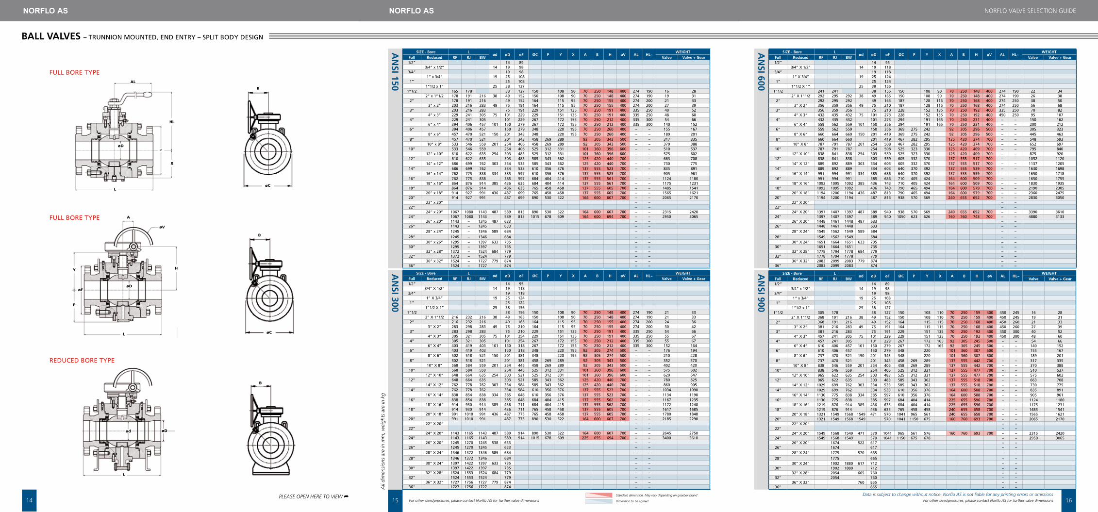
BAll VAlVES – TRUNNION MOUNTED, END ENTRY – SPLIT BODY DESIGN SiZE - Bore l
ød ød øf øc p y X A B h øV Al hl~WEiGhT
full reduced rf rJ BW Valve Valve + Gear1/2” 14 89
3/4” x 1/2” 14 19 983/4” 19 98
1” x 3/4” 19 25 1081” 25 108
1”1/2 x 1” 25 38 1271”1/2 165 178 38 127 150 108 90 70 250 148 400 274 190 16 28
2” x 1”1/2 178 191 216 38 49 152 150 108 90 70 250 148 400 274 190 19 312” 178 191 216 49 152 164 115 95 70 250 155 400 274 200 21 33
3” x 2” 203 216 283 49 75 191 164 115 95 70 250 155 400 274 200 27 393” 203 216 283 75 191 229 151 135 70 250 191 400 335 250 40 52
4” x 3” 229 241 305 75 101 229 229 151 135 70 250 191 400 335 250 48 604” 229 241 305 101 229 267 172 155 70 250 212 400 335 300 54 66
6” x 4” 394 406 457 101 150 279 267 172 155 70 250 212 400 335 300 140 1526” 394 406 457 150 279 348 220 195 70 250 260 400 – – 155 167
8” x 6” 457 470 521 150 201 343 348 220 195 70 250 260 400 – – 189 2018” 457 470 521 201 343 458 269 289 92 305 343 500 – – 317 335
10” x 8” 533 546 559 201 254 406 458 269 289 92 305 343 500 – – 370 38810” 533 546 559 254 406 525 312 331 101 360 396 600 – – 510 537
12” x 10” 610 622 635 254 303 483 525 312 331 101 360 396 600 – – 575 60212” 610 622 635 303 483 585 343 362 125 420 440 700 – – 663 708
14” x 12” 686 699 762 303 334 533 585 343 362 125 420 440 700 – – 730 77514” 686 699 762 334 533 610 356 376 137 555 523 700 – – 835 891
16” x 14” 762 775 838 334 385 597 610 356 376 137 555 523 700 – – 905 96116” 762 775 838 385 597 684 404 414 137 555 561 700 – – 1124 1180
18” x 16” 864 876 914 385 436 635 684 404 414 137 555 561 700 – – 1175 123118” 864 876 914 436 635 765 458 458 137 555 605 700 – – 1485 1541
20” x 18” 914 927 991 436 487 699 765 458 458 137 555 605 700 – – 1565 162120” 914 927 991 487 699 890 530 522 164 600 607 700 – – 2065 2170
22” x 20” – –22” – –
24” x 20” 1067 1080 1143 487 589 813 890 530 522 164 600 607 700 – – 2315 242024” 1067 1080 1143 589 813 1015 678 609 164 600 694 700 – – 2950 3065
26” x 20” 1143 – 1245 487 633 – –26” 1143 – 1245 633 – –
28” x 24” 1245 – 1346 589 684 – –28” 1245 – 1346 684 – –
30” x 26” 1295 – 1397 633 735 – –30” 1295 – 1397 735 – –
32” x 28” 1372 – 1524 684 779 – –32” 1372 – 1524 779 – –
36” x 32” 1524 – 1727 779 874 – –36” 1524 – 1727 874 – –
AN
Si 150
AN
Si 600
AN
Si 300
AN
Si 900
SiZE - Bore lød ød øf øc p y X A B h øV Al hl~
WEiGhTfull reduced rf rJ BW Valve Valve + Gear1/2” 14 95
3/4” x 1/2” 14 19 1183/4” 19 118
1” x 3/4” 19 25 1241” 25 124
1”1/2 x 1” 25 38 1561”1/2 241 241 38 156 150 108 90 70 250 148 400 274 190 22 34
2” x 1”1/2 292 295 292 38 49 165 150 108 90 70 250 148 400 274 190 26 382” 292 295 292 49 165 187 128 115 70 250 168 400 274 250 38 50
3” x 2” 356 359 356 49 75 210 187 128 115 70 250 168 400 274 250 56 683” 356 359 356 75 210 228 152 135 70 250 192 400 335 250 70 82
4” x 3” 432 435 432 75 101 273 228 152 135 70 250 192 400 450 250 95 1074” 432 435 432 101 273 294 191 165 70 250 231 400 – – 150 162
6” x 4” 559 562 559 101 150 356 294 191 165 70 250 231 400 – – 200 2126” 559 562 559 150 356 369 275 242 92 305 296 500 – – 305 323
8” x 6” 660 664 660 150 201 419 369 275 242 92 305 296 500 – – 445 4638” 660 664 660 201 419 467 282 295 125 420 374 700 – – 548 593
10” x 8” 787 791 787 201 254 508 467 282 295 125 420 374 700 – – 652 69710” 787 791 787 254 508 525 323 330 125 420 409 700 – – 795 840
12” x 10” 838 841 838 254 303 559 525 323 330 125 420 409 700 – – 875 92012” 838 841 838 303 559 605 332 370 137 555 517 700 – – 1052 1120
14” x 12” 889 892 889 303 334 603 605 332 370 137 555 517 700 – – 1137 120514” 889 892 889 334 603 640 370 392 137 555 539 700 – – 1630 1698
16” x 14” 991 994 991 334 385 686 640 370 392 137 555 539 700 – – 1650 171816” 991 994 991 385 686 710 405 424 164 600 509 700 – – 1650 1755
18” x 16” 1092 1095 1092 385 436 743 710 405 424 164 600 509 700 – – 1830 193518” 1092 1095 1092 436 743 790 465 494 164 600 579 700 – – 2190 2305
20” x 18” 1194 1200 1194 436 487 813 790 465 494 164 600 579 700 – – 2360 247520” 1194 1200 1194 487 813 938 570 569 240 655 692 700 – – 2830 3050
22” x 20” – –22” – –
24” x 20” 1397 1407 1397 487 589 940 938 570 569 240 655 692 700 – – 3390 361024” 1397 1407 1397 589 940 1050 623 626 160 760 743 700 – – 4880 5133
26” x 20” 1448 1461 1448 487 633 – –26” 1448 1461 1448 633 – –
28” x 24” 1549 1562 1549 589 684 – –28” 1549 1562 1549 684 – –
30” x 24” 1651 1664 1651 633 735 – –30” 1651 1664 1651 735 – –
32” x 28” 1778 1794 1778 684 779 – –32” 1778 1794 1778 779 – –
36” x 32” 2083 2099 2083 779 874 – –36” 2083 2099 2083 874 – –
SiZE - Bore lød ød øf øc p y X A B h øV Al hl~
WEiGhTfull reduced rf rJ BW Valve Valve + Gear1/2” 14 95
3/4” x 1/2” 14 19 1183/4” 19 118
1” x 3/4” 19 25 1241” 25 124
1”1/2 x 1” 25 38 1561”1/2 38 156 150 108 90 70 250 148 400 274 190 21 33
2” x 1”1/2 216 232 216 38 49 165 150 108 90 70 250 148 400 274 190 21 332” 216 232 216 49 165 164 115 95 70 250 155 400 274 200 24 36
3” x 2” 283 298 283 49 75 210 164 115 95 70 250 155 400 274 200 30 423” 283 298 283 75 210 229 151 135 70 250 191 400 335 250 54 66
4” x 3” 305 321 305 75 101 254 229 151 135 70 250 191 400 335 250 55 674” 305 321 305 101 254 267 172 155 70 250 212 400 335 300 55 67
6” x 4” 403 419 403 101 150 318 267 172 155 70 250 212 400 335 300 152 1646” 403 419 403 150 318 348 220 195 92 305 274 500 – – 176 194
8” x 6” 502 518 521 150 201 381 348 220 195 92 305 274 500 – – 210 2288” 502 518 521 201 381 458 269 289 92 305 343 500 – – 352 370
10” x 8” 568 584 559 201 254 445 458 269 289 92 305 343 500 – – 402 42010” 568 584 559 254 445 525 312 331 101 360 396 600 – – 575 602
12” x 10” 648 664 635 254 303 521 525 312 331 101 360 396 600 – – 620 64712” 648 664 635 303 521 585 343 362 125 420 440 700 – – 780 825
14” x 12” 762 778 762 303 334 584 585 343 362 125 420 440 700 – – 860 90514” 762 778 762 334 584 610 356 376 137 555 523 700 – – 1034 1090
16” x 14” 838 854 838 334 385 648 610 356 376 137 555 523 700 – – 1134 119016” 838 854 838 385 648 684 404 415 137 555 562 700 – – 1167 1235
18” x 16” 914 930 914 385 436 711 684 404 415 137 555 562 700 – – 1172 124018” 914 930 914 436 711 765 458 458 137 555 605 700 – – 1617 1685
20” x 18” 991 1010 991 436 487 775 765 458 458 137 555 605 700 – – 1780 184820” 991 1010 991 487 775 890 530 522 164 600 607 700 – – 2185 2290
22” x 20” – –22” – –
24” x 20” 1143 1165 1143 487 589 914 890 530 522 164 600 607 700 – – 2645 275024” 1143 1165 1143 589 914 1015 678 609 225 655 694 700 – – 3400 3610
26” x 20” 1245 1270 1245 538 633 – –26” 1245 1270 1245 633 – –
28” x 24” 1346 1372 1346 589 684 – –28” 1346 1372 1346 684 – –
30” x 24” 1397 1422 1397 633 735 – –30” 1397 1422 1397 735 – –
32” x 28” 1524 1553 1524 684 779 – –32” 1524 1553 1524 779 – –
36” x 32” 1727 1756 1727 779 874 – –36” 1727 1756 1727 874 – –
SiZE - Bore lød ød øf øc p y X A B h øV Al hl~
WEiGhTfull reduced rf rJ BW Valve Valve + Gear1/2” 14 89
3/4” x 1/2” 14 19 983/4” 19 98
1” x 3/4” 19 25 1081” 25 108
1”1/2 x 1” 25 38 1271”1/2 305 178 38 127 150 108 110 70 250 159 400 450 245 16 28
2” x 1”1/2 368 191 216 38 49 152 150 108 110 70 250 159 400 450 245 19 312” 368 191 216 49 152 164 115 115 70 250 168 400 450 260 21 33
3” x 2” 381 216 283 49 75 191 164 115 115 70 250 168 400 450 260 27 393” 381 216 283 75 191 229 151 135 70 250 192 400 450 300 40 52
4” x 3” 457 241 305 75 101 229 229 151 135 70 250 192 400 450 300 48 604” 457 241 305 101 229 267 172 165 92 305 245 500 – – 54 66
6” x 4” 610 406 457 101 150 279 267 172 165 92 305 245 500 – – 140 1526” 610 406 457 150 279 348 220 101 360 307 600 – – 155 167
8” x 6” 737 470 521 150 201 343 348 220 101 360 307 600 – – 189 2018” 737 470 521 201 343 458 269 289 137 555 442 700 – – 317 335
10” x 8” 838 546 559 201 254 406 458 269 289 137 555 442 700 – – 370 38810” 838 546 559 254 406 525 312 331 137 555 477 700 – – 510 537
12” x 10” 965 622 635 254 303 483 525 312 331 137 555 477 700 – – 575 60212” 965 622 635 303 483 585 343 362 137 555 518 700 – – 663 708
14” x 12” 1029 699 762 303 334 533 585 343 362 137 555 518 700 – – 730 77514” 1029 699 762 334 533 610 356 376 164 600 508 700 – – 835 891
16” x 14” 1130 775 838 334 385 597 610 356 376 164 600 508 700 – – 905 96116” 1130 775 838 385 597 684 404 414 225 655 596 700 – – 1124 1180
18” x 16” 1219 876 914 385 436 635 684 404 414 225 655 596 700 – – 1175 123118” 1219 876 914 436 635 765 458 458 240 655 658 700 – – 1485 1541
20” x 18” 1321 1549 1568 1549 471 570 1041 965 561 240 655 658 700 – – 1565 162120” 1321 1549 1568 1549 570 1041 1150 675 160 760 693 700 – – 2065 2170
22” x 20” – –22” – –
24” x 20” 1549 1568 1549 471 570 1041 965 561 576 160 760 693 700 – – 2315 242024” 1549 1568 1549 570 1041 1150 675 678 – – 2950 3065
26” x 20” 1674 522 617 – –26” 1674 617 – –
28” x 24” 1775 570 665 – –28” 1775 665 – –
30” x 24” 1902 1880 617 712 – –30” 1902 1880 712 – –
32” x 28” 2054 665 760 – –32” 2054 760 – –
36” x 32” 760 855 – –36” 855 – –
FULL BORE TYPE
FULL BORE TYPE
REDUCED BORE TYPE
L
L
P
Y
X
hL
AL
b
b
b
øD
øC
øC
A
øV
h
øD
ød øD
øF
L
PLEASE OPEN HERE TO VIEW Data is subject to change without notice. Norflo AS is not liable for any printing errors or omissionsFor other sizes/pressures, please contact Norflo AS for further valve dimensions
➥
17
NOrflO ValVe SelectION GUIDe NOrflO ValVe SelectION GUIDe
19
AN
Si 1500A
NSi 2500
SiZE - Bore lød ød øf øc p y X A B h øV Al hl~
WEiGhTfull reduced rf rJ BW Valve Valve + Gear1/2” 14 133
3/4” x 1/2” 273 273 14 19 1403/4” 273 273 19 140
1” x 3/4” 308 308 19 25 1591” 308 308 25 159 148 108 90 274 185 30 42
1”1/2 x 1” 384 387 25 38 203 148 108 90 274 185 40 521”1/2 384 387 38 203 187 124 120 70 250 164 400 450 260 60 72
2” x 1”1/2 451 454 451 38 44 235 187 124 120 70 250 164 400 450 260 80 922” 451 454 451 44 235 208 143 130 92 305 197 500 – – 97 115
3” x 2” 578 584 578 44 62 305 208 143 130 92 305 197 500 – – 165 1833” 578 584 578 62 305 320 205 180 92 305 259 500 – – 336 354
4” x 3” 673 683 673 62 87 356 320 205 180 92 305 259 500 – – 337 3554” 673 683 673 87 356 325 185 218 125 420 297 700 – – 337 382
6” x 4” 914 927 914 87 131 483 325 185 218 125 420 297 700 – – 540 5856” 914 927 914 131 483 480 285 305 137 555 452 700 – – 863 931
8” x 6” 1022 1038 1022 131 179 552 480 285 305 137 555 452 700 – – 1150 12188” 1022 1038 1022 179 552 615 368 381 164 600 466 700 – – 1575 1680
10” x 8” 1270 1292 1270 179 223 673 615 368 381 164 600 466 700 – – 1750 185510” 1270 1292 1270 223 673 850 485 504 164 600 589 700 – – 3400 3515
12” x 10” 1422 1445 1422 223 265 762 850 485 504 164 600 589 700 – – 3560 367512” 1422 1445 1422 265 762 915 495 540 225 655 663 700 – – 3710 3920
14” x 12” – –14” – –
16” x 14” – –16” – –
18” x 16” – –18” – –
20” x 18” – –20” – –
22” x 20” – –22” – –
24” x 20” – –24” – –
SIZE - Bore Lød øD øF øC P Y x A B H øV AL HL~
WEIGHTFull Reduced RF RJ BW Valve Valve + Gear1/2” 14 121
3/4” x 1/2” 14 19 1303/4” 19 130
1” x 3/4” 19 25 1491” 25 149
1”1/2 x 1” 25 38 1781”1/2 305 305 38 178 176 119 110 70 250 159 400 38 50
2” x 1”1/2 368 371 368 38 49 216 176 119 110 70 250 159 400 450 245 57 692” 368 371 368 49 216 187 128 115 70 250 168 400 450 260 62 74
3” x 2” 470 473 470 49 75 267 187 128 115 70 250 168 400 450 260 85 973” 470 473 470 75 267 228 143 125 92 305 197 500 – – 110 128
4” x 3” 546 549 546 75 101 311 228 143 125 92 305 197 500 – – 139 1574” 546 549 546 101 311 300 205 170 101 360 270 600 – – 205 232
6” x 4” 705 711 705 101 144 394 300 205 170 101 360 270 600 – – 302 3296” 705 711 705 144 394 420 280 274 137 555 421 700 – – 514 570
8” x 6” 832 841 832 144 192 483 420 280 274 137 555 421 700 – – 670 7268” 832 841 832 192 483 520 340 328 137 555 475 700 – – 737 805
10” x 8” 991 1000 991 192 239 584 520 340 328 137 555 475 700 – – 955 102310” 991 1000 991 239 584 590 377 369 164 600 454 700 – – 1360 1465
12” x 10” 1130 1146 1130 239 287 673 590 377 369 164 600 454 700 – – 1560 166512” 1130 1146 1130 287 673 760 440 457 164 600 542 700 – – 2500 2615
14” x 12” 1257 1276 1257 287 315 749 760 440 457 164 600 542 700 – – 2620 273514” 1257 1276 1257 315 749 780 485 470 164 600 555 700 – – 3020 3135
16” x 14” 1384 1407 1384 315 360 826 780 485 470 164 600 555 700 – – 3350 346516” 1384 1407 1384 360 826 880 539 524 225 655 647 700 – – 4260 4470
18” x 16” 914 225 655 700 – – 1830 193518” 914 240 655 700 – – 2190 2305
20” x 18” 984 240 655 700 – – 2360 247520” 984 160 760 700 – – 2830 3050
22” x 20” – –22” – –
24” x 20” 1168 160 760 700 – – 3390 361024” 1168 – – 4880 5133
26” x 20” – –26” – –
28” x 24” – –28” – –
30” x 24” – –30” – –
32” x 28” – –32” – –
36” x 32” – –36” – –
18
All
dim
ensi
ons
are
in m
m, w
eigh
ts a
re in
kg
SiZE - Bore lød ød øf Al hl WEiGhT
full reduced rf rJ BW
1/2” 108 121 - 14 89 180 85 3
3/4” x 1/2” 117 130 - 14 19 98 180 85 3
3/4” 117 130 - 19 98 180 85 3
1” x 3/4” 127 140 - 19 25 108 215 120 5
1” 127 140 - 25 108 215 120 5
1”1/2 x 1”1/4 165 178 - 32 38 127 215 130 9
1”1/2” 165 178 - 38 127 215 130 9
2” x 1”1/2 178 191 216 38 49 152 215 130 10
2” 178 191 216 49 152 215 130 14
3” x 2” 203 216 283 49 75 191 274 170 20
3” 203 216 283 75 191 274 170 24
4” x 3” 229 241 305 75 101 229 335 215 43
4” 229 241 305 101 229 335 215 46
6” x 4” 394 406 457 101 150 279 500 250 83
6” 394 406 457 150 279 500 270 121
ANSi 150SiZE - Bore l
ød ød øf Al hl WEiGhTfull reduced rf rJ BW
1/2” 140 151 - 14 95 180 85 5
3/4” x 1/2” 152 165 - 14 19 118 215 130 6
3/4” 152 165 - 19 118 215 130 6
1” x 3/4” 165 178 - 19 25 124 215 130 7
1” 165 178 - 25 124 215 130 8
1”1/2 x 1”1/4 191 203 - 32 38 156 215 130 13
1”1/2” 191 203 - 38 156 215 130 13
2” x 1”1/2 216 232 216 38 49 165 274 145 16
2” 216 232 216 49 165 274 145 16
3” x 2” 283 298 283 49 75 210 335 160 32
3” 283 298 283 75 210 335 190 38
4” x 3” 305 321 305 75 101 254 335 210 56
4” 305 321 305 101 254 335 250 78
6” x 4” 394 406 457 101 150 279 500 250 83
6” 394 406 457 150 279 500 270 121
ANSi 300
SiZE - Bore lød ød øf Al hl WEiGhT
full reduced rf rJ BW
1/2” 216 216 - 14 121 215 120 8
3/4” x 1/2” 229 229 - 14 19 130 215 125 10
3/4” 229 229 - 19 130 215 125 10
1” x 3/4” 254 254 - 19 25 149 274 125 12
1” 254 254 - 25 149 274 125 14
1”1/2 x 1”1/4 305 305 - 32 38 178 274 145 25
1”1/2 305 305 - 38 178 274 145 28
2” x 1”1/2 368 371 368 38 49 216 335 160 30
2” 368 371 368 49 216 335 160 34
ANSi 1500SiZE - Bore l
ød ød øf Al hl WEiGhTfull reduced rf rJ BW
1/2” 264 264 - 14 133 215 120 11
3/4” x 1/2” 273 273 - 14 19 140 274 125 13
3/4” 273 273 - 19 140 274 125 14
1” x 3/4” 308 308 - 19 25 159 274 130 17
1” 308 308 - 25 159 274 130 19
1”1/2 x 1”1/4 384 387 - 32 38 203 450 210 51
1”1/2 384 387 - 38 203 450 210 51
ANSi 300
SiZE - Bore lød ød øf Al hl WEiGhT
full reduced rf rJ BW
1/2” 165 165 - 14 95 180 80 4
3/4” x 1/2” 191 191 - 14 19 118 215 80 5
3/4” 191 191 - 19 118 215 135 7
1” x 3/4” 216 216 - 19 25 124 215 120 8
1” 216 216 - 25 124 215 120 8
1”1/2 x 1”1/4 241 241 - 32 38 156 274 130 15
1”1/2 241 241 - 38 156 274 140 16
2” x 1”1/2 292 295 292 38 49 165 274 140 20
2” 292 295 292 49 165 274 140 20
3” x 2” 356 359 356 49 75 210 335 190 40
3” 356 359 356 75 210 335 190 46
ANSi 600SiZE - Bore l
ød ød øf Al hl WEiGhTfull reduced rf rJ BW
1/2” 216 216 - 14 121 215 120 8
3/4” x 1/2” 229 229 - 14 19 130 215 125 10
3/4” 229 229 - 19 130 215 125 10
1” x 3/4” 254 254 - 19 25 149 274 125 12
1” 254 254 - 25 149 274 125 14
1”1/2 x 1”1/4 305 305 - 32 38 178 274 145 25
1”1/2 305 305 - 38 178 274 145 28
2” x 1”1/2 368 371 368 38 49 216 335 160 30
2” 368 371 368 49 216 335 160 34
ANSi 900
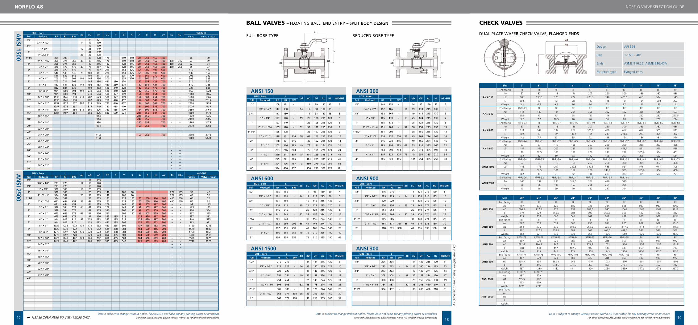
bALL VALVES – FLOATING BALL, END ENTRY – SPLIT BODY DESIGN
FULL BORE TYPE REDUCED BORE TYPE
PLEASE OPEN HERE TO VIEW MORE DATA➥
ChECK VALVES
DUAL PLATE WAFER CHECK VALVE, FLANGED ENDS
Size 2" 3" 4" 6" 8" 10" 12" 14" 16" 18"
ANSi 150
end facing rf rf rf rf rf rf rf rf rf rf
aø 57 87 113 166 207 260 300 339 387 438
cØ 105 136,5 175 222 279,5 340 409,5 451 514 549
l 60,5 73 73 98 127 146 181 184 190,5 203
Weight 3,2 6,5 9,5 16 36 52 97 123 133 141
ANSi 300
end facing rf/rJ-23 rf rf rf rf rf rf rf rf rf
aø 111 149 181 251 308 362 422 486 540 597
l 60,5 73 73 98 127 146 181 222 232 263,5
Weight 3,2 7,7 10,5 20 40 56 98 176 207 294
ANSi 600
end facing rf/rJ-23 rf rf/rJ-37 rf/rJ-45 rf/rJ-49 rf/rJ-53 rf/rJ-57 rf/rJ-61 rf/rJ-65 rf/rJ-69
aø 57 87 113 166 207 260 300 339 387 438
cØ 111 149 194 267 320,6 400 457 492 565 613
l 60,5 73 79 136,5 165 213 228,6 273 305 362
Weight 3,2 7,7 13 35 72 118 164 186 331 394
ANSi 900
end facing rf/rJ-24 rf/rJ-31 rf/rJ-37 rf/rJ-45 rf/rJ-49 rf/rJ-53 rf/rJ-57 rf/rJ-62 rf/rJ-66 rf/rJ-70
aø 57 87 113 166 207 260 300 339 387 438
cØ 143 169 207 289 359 435 498,5 521 575 638
l 70 82,5 101 159 206 241 292 355,6 384 451
Weight 8,2 12 19 54 122 196 293 396 532 611
ANSi 1500
end facing rf/rJ-24 rf/rf-35 rf/rJ-39 rf/rJ-46 rf/rJ-50 rf/rJ-54 rf/rJ-58 rf/rJ-63 rf/rJ-67 rf/rJ-71aø 57 87 113 166 207 260 300 339 387 438
cØ 143 175 207 282,5 352.5 435 521 578 641 705
l 70 82,5 101 159 206 247,6 305 355,6 384 468
Weight 8,2 13 21 52 116 203 373 484 587 791
ANSi 2500
end facing rf/rJ-26 rf/rf-32 rf/rJ-38 rf/rJ-47 rf/rJ-51 rf/rJ-55 rf/rJ-60
aø 146 197 235 317,5 387 476 549
l 70 86 105 159 206 254 305
Weight 13 16 29 70 132 217 394
Size 20" 24" 26" 28" 30" 32" 36" 40" 42" 48"
ANSi 150
end facing rf rf rf rf rf rf rf rf rf rfaø 487 579 629 680 735 784 865 987 987 1062cØ 606,5 717,5 775 832 882,5 940 1048 1162 1162 1219l 219 222 355,5 381 305 355,5 368 432 432 432
Weight 215 358 680 544 662 707 682 900 968 1134
ANSi 300
end facing rf rf rf rf rf rf rf rf rf rfaø 487 579 629 680 735 784 865 909 909 1015cØ 654 775 835 898,5 952,5 1006,5 1117,5 1114 1114 1168l 292 317,5 355,5 381 368 406,5 482,5 546 546 568
Weight 363 521 735 733 952 1635 1269 1825 1825 2630
ANSi 600
end facing rf/rJ-73 rf/rJ-77 rf/rJ-73 rf/rJ-94 rf/rJ-95 rf/rJ-96 rf/rJ-98 rf rf rfaø 487 579 629 680 735 784 865 909 909 972cØ 682,6 790,5 867 914 971,5 1022 1130 1156 1156 1219l 368 438 457 482,5 505 533 635 660 660 702
Weight 544 819 842 871 1578 1743 2120 3750 3750 3135
ANSi 900
end facing rf/rJ-74 rf/rJ-78 rf/rJ-100 rf/rJ-101 rf/rJ-102 rf/rJ-105 rf/rJ-105 rf rf rfaø 487 579 629 680 735 784 865 909 909 972cØ 698,5 838 882,5 946 1010 1073 1200 1251 1251 1302l 451 495 533,5 571,5 365 660 717,5 762 762 787
Weight 637 1230 1182 1441 1820 2034 3259 3972 3972 3670
ANSi 1500
end facing rf/rJ-75 rf/rJ-79aø 487 579cØ 755,5 902l 533 559
Weight 1275 2713
ANSi 2500
end facingaøcØl
Weight
Design aPI 594
Size 1-1/2” - 40”
ends aSMe B16.25, aSMe B16.47a
Structure type flanged ends
AL
HL
øF
L
øD øD øF
Data is subject to change without notice. Norflo AS is not liable for any printing errors or omissionsFor other sizes/pressures, please contact Norflo AS for further valve dimensions
Data is subject to change without notice. Norflo AS is not liable for any printing errors or omissionsFor other sizes/pressures, please contact Norflo AS for further valve dimensions
Data is subject to change without notice. Norflo AS is not liable for any printing errors or omissionsFor other sizes/pressures, please contact Norflo AS for further valve dimensions
20
NOrflO ValVe SelectION GUIDe
21
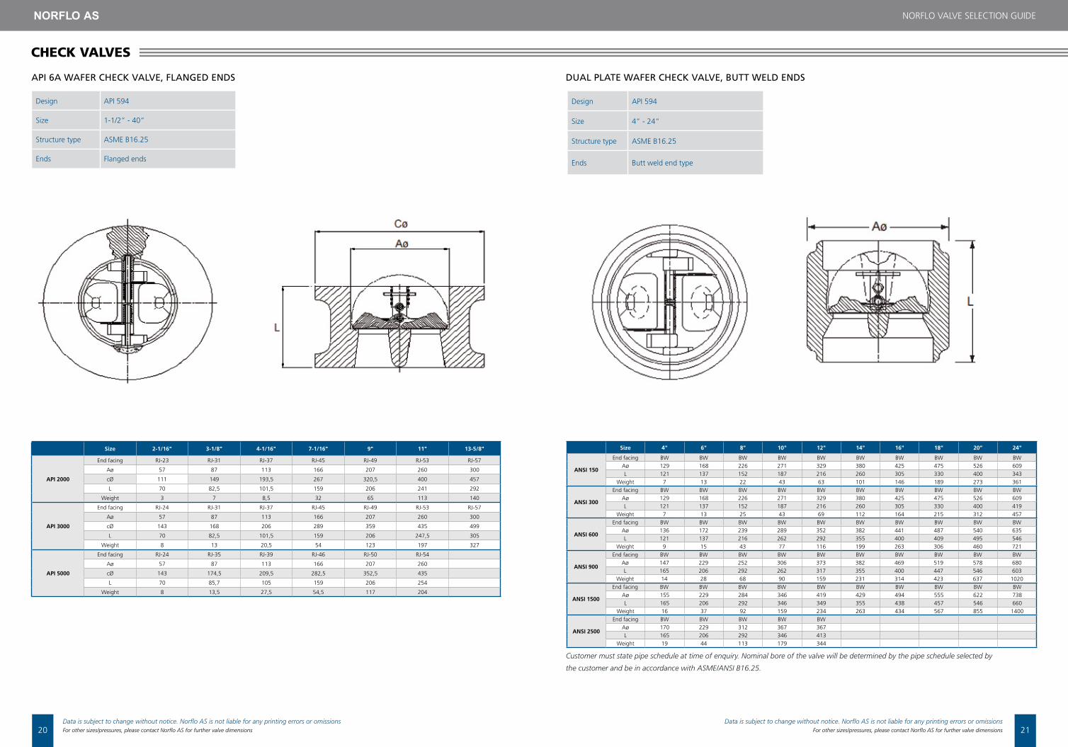
API 6A WAFER CHECK VALVE, FLANGED ENDS DUAL PLATE WAFER CHECK VALVE, BUTT WELD ENDS
Size 4" 6" 8" 10" 12" 14" 16" 18" 20” 24"
ANSi 150
end facing BW BW BW BW BW BW BW BW BW BWaø 129 168 226 271 329 380 425 475 526 609l 121 137 152 187 216 260 305 330 400 343
Weight 7 13 22 43 63 101 146 189 273 361
ANSi 300
end facing BW BW BW BW BW BW BW BW BW BWaø 129 168 226 271 329 380 425 475 526 609l 121 137 152 187 216 260 305 330 400 419
Weight 7 13 25 43 69 112 164 215 312 457
ANSi 600
end facing BW BW BW BW BW BW BW BW BW BWaø 136 172 239 289 352 382 441 487 540 635l 121 137 216 262 292 355 400 409 495 546
Weight 9 15 43 77 116 199 263 306 460 721
ANSi 900
end facing BW BW BW BW BW BW BW BW BW BWaø 147 229 252 306 373 382 469 519 578 680l 165 206 292 262 317 355 400 447 546 603
Weight 14 28 68 90 159 231 314 423 637 1020
ANSi 1500
end facing BW BW BW BW BW BW BW BW BW BWaø 155 229 284 346 419 429 494 555 622 738l 165 206 292 346 349 355 438 457 546 660
Weight 16 37 92 159 234 263 434 567 855 1400
ANSi 2500
end facing BW BW BW BW BWaø 170 229 312 367 367l 165 206 292 346 413
Weight 19 44 113 179 344
Size 2-1/16" 3-1/8" 4-1/16" 7-1/16" 9" 11" 13-5/8"
Api 2000
end facing rJ-23 rJ-31 rJ-37 rJ-45 rJ-49 rJ-53 rJ-57
aø 57 87 113 166 207 260 300
cØ 111 149 193,5 267 320,5 400 457
l 70 82,5 101,5 159 206 241 292
Weight 3 7 8,5 32 65 113 140
Api 3000
end facing rJ-24 rJ-31 rJ-37 rJ-45 rJ-49 rJ-53 rJ-57
aø 57 87 113 166 207 260 300
cØ 143 168 206 289 359 435 499
l 70 82,5 101,5 159 206 247,5 305
Weight 8 13 20,5 54 123 197 327
Api 5000
end facing rJ-24 rJ-35 rJ-39 rJ-46 rJ-50 rJ-54
aø 57 87 113 166 207 260
cØ 143 174,5 209,5 282,5 352,5 435
l 70 85,7 105 159 206 254
Weight 8 13,5 27,5 54,5 117 204
Design aPI 594
Size 1-1/2” - 40”
Structure type aSMe B16.25
ends flanged ends
Design aPI 594
Size 4” - 24”
Structure type aSMe B16.25
ends Butt weld end type
Customer must state pipe schedule at time of enquiry. Nominal bore of the valve will be determined by the pipe schedule selected by
the customer and be in accordance with ASME/ANSI B16.25.
ChECK VALVES
NOrflO ValVe SelectION GUIDe
Data is subject to change without notice. Norflo AS is not liable for any printing errors or omissionsFor other sizes/pressures, please contact Norflo AS for further valve dimensions
Data is subject to change without notice. Norflo AS is not liable for any printing errors or omissionsFor other sizes/pressures, please contact Norflo AS for further valve dimensions

22 23
NOrflO ValVe SelectION GUIDe
Design aPI 602, BS 5352
Size 1/4” - 2”
endsSocket weld ends to aNSI B.16.11, screwed ends (NPt) to aNSI B1.20.1,butt weld ends to aNSI B.16.25
face to face aNSI B16.34
Structure type Bolted bonnet, standard bore, outside screw & yoke
Norflo/Manufacturer standard
Norflo/Manufacturer standard
GATE VALVE, BOLTED BONNET - STANDARD BORE, OUTSIDE SCREW & YOKE
Size, inches 1/4" 3/8" 1/2" 3/4" 1" 1-1/4" 1-1/2" 2"
ANSi 800
end facing SW/BW SW/BW SW/BW SW/BW SW/BW SW/BW SW/BW SW/BW
aø 8 9.6 14 18 24 30 36.5 48
B 148 148 163 178 210 243 262 365
l 80 80 90 110 127 127 127 210
Weight 1.6 1.6 2.2 3.5 5 6.5 9 21.5
ANSi 1500
end facing SW/BW SW/BW SW/BW SW/BW SW/BW SW/BW SW/BW SW/BW
aø 8 9.6 14 18 24 30 37 40
B 145 160 175 210 240 260 355 360
l 90 90 110 120 130 130 150 210
Weight 2.2 2.2 3.8 5.5 6.8 9.5 22.5 22.5
Size, inches 1/2" 3/4" 1" 1-1/4" 1-1/2" 2"
ANSi 800
end facing SW/BW SW/BW SW/BW SW/BW SW/BW SW/BW
aø 10 14 18 24 30 37
B 148 163 178 210 243 262
l 90 110 127 127 127 210
Weight 1.6 2.2 3.5 5 7 9
ANSi 1500
end facing SW/BW SW/BW SW/BW SW/BW SW/BW SW/BW
aø 9,6 14 18 24 30 37
B 160 175 210 240 260 355
l 90 110 127 127 127 210
Weight 2.2 3.8 5.5 6.8 9.5 22.5
GATE VALVES
Design aPI 602, BS 5352
Size 1/4” - 2”
endsSocket weld ends to aNSI B.16.11, screwed ends (NPt) to aNSI B1.20.1,butt weld ends to aNSI B.16.25
face to face Screwed ends (NPt) to aNSI B1.20.1
Structure type Bolted Bonnet, reduced bore, outside screw & yoke
BOLTED BONNET - REDUCED BORE, OUTSIDE SCREW & YOKE
Aø= Diameter of port B= Center to top L= End to end
Aø= Diameter of port B= Center to top L= End to end
Size 2" 2-1/2" 3" 4" 6" 8" 10" 12"
ANSi 150
B 132 173 208 254 308 330 362 362
l/rf/BW 203 241 292 356 495 622 698 698
l/rtJ 216 254 305 369 508 635 711 711
Weight (approx.) 16 27 45 73 132 238 295 295
ANSi 300
B 152 200 238 287 352 398 450 450
l/rf/BW 267 318 356 444 533 622 711 711
l/rtJ 283 334 372 460 549 638 727 727
Weight (approx.) 18 48 67 128 240 335 549 549
ANSi 600
B 197 225 262 335 440 472 482 482
l/rf/BW 292 356 432 559 600 787 838 838
l/rtJ 295 359 435 562 663 790 840 840
Weight (approx.) 33 65 112 220 385 465 730 730
ANSi 900
B 240 255 300 370 450 515 630 630
l/rf/BW 368 381 457 610 737 838 965 965
l/rtJ 371 384 460 613 740 841 968 968
Weight (approx.) 69 78 120 265 385 600 860
ANSi 1500
B 240 300 340 475 525 640 760 760
l/rf/BW 368 470 543 705 832 991 1130 1130
l/rtJ 371 473 549 711 842 1000 1146 1146
Weight (approx.) 75 120 235 540 945 1275 1870
ANSi 2500
B 280 360 420 560 700 810 920 920
l/rf/BW 451 578 673 914 1022 1270 1422 1422
l/rtJ 454 584 683 927 1038 1293 1444 1444
Weight (approx.) 90 155 275 735 1210 1450 2200
SWING CHECK VALVE
Design BS 1868, aPI 6D, aNSI B16.34
Size 2” - 36”
ends flanges to aSMe B16.5 from 2” - 24”, flanges to aSMe B16.47 from 26”, butt weld ends to aNSI B.16.25
face to face aSMe B16.10 / aPI 6D
Structure type Bolted cover, swing type disc
B= Center to top L= End to end
ChECK VALVES
Data is subject to change without notice. Norflo AS is not liable for any printing errors or omissionsFor other sizes/pressures, please contact Norflo AS for further valve dimensions
Data is subject to change without notice. Norflo AS is not liable for any printing errors or omissionsFor other sizes/pressures, please contact Norflo AS for further valve dimensions

24
NOrflO ValVe SelectION GUIDe
25
Design aPI 600, BS eN ISO 10434, aNSI B16.34
Size 2” - 48”
endsflanges to aSMe B16.5 from 2”” - 24”, flanges to aSMe B16.47 from 26”, butt weld ends to aNSI B.16.25
face to face aSMe B16.10
Structure type Bolted bonnet, OS&Y, solid or flexible wedge
Design aPI 600, BS eN ISO 10434, aNSI B16.34
Size 1” - 36”
ends Butt weld ends to aNSI B16.25
face to face aNSI B16.10
Structure type Pressure seal, outside screw & yoke
Aø= Diameter of port B= Center to top L= End to end G.O= Gear operated
Aø= Diameter of port B= Center to top L= End to end G.O= Gear operated
GATE VALVE, BOLTED BONNET, OS&Y, SOLID OR FLExIBLE WEDGE
GATE VALVE, PRESSURE SEAL - OUTSIDE SCREW & YOKE
Size, inches 2" 3" 4" 6" 8" 10" 12"
ANSi 900
end facing BW BW BW BW BW BW BW
B 670 791 1068 1380 1560 1800 1900
l 305 356 508 660 787 914 991
V 500 500 600 600 G.O G.O G.O
ANSi 1500
end facing BW BW BW BW BW BW BW
B 590 680 795 1175 1394 1580 1780
l 216 305 406 559 711 864 991
V 500 500 600 600 G.O G.O G.O
ANSi 2500
end facing BW BW BW BW BW BW BW
B 680 735 885 1152 1302 1576 1665
l 279 368 457 610 762 914 1041
V 500 500 600 G.O G.O G.O G.O
Size 2" 3" 4" 6" 8" 10" 12"
ANSi 150
B 375 472 577 806 979 1178 1416l - rf 178 203 229 267 292 330 356l - rtJ 191 216 242 280 305 343 369l/BW 216 282 305 403 419 457 502
V 200 225 250 300 350 400 450Weight (approx.) 18 31 51 84 132 205 290
ANSi 300
B 409 506 605 842 1030 1295 1472l - rf/BW 216 282 305 403 419 457 502
l - rtJ 232 298 321 419 435 473 518
V 200 225 250 350 400 450 500Weight (approx.) 27 44 70 132 208 375 445
ANSi 600
B 418 538 644 905 1332 1410 1740l - rf/BW 292 356 432 559 660 787 838
l - rtJ 295 359 435 562 663 790 840
V 200 250 300 450 500 600 720Weight (approx.) 37 61 112 215 365 682 975
ANSi 900
B 438 590 685 930 1140 1340 1750
l - rf/BW 368 381 457 610 737 838 965
l - rtJ 371 384 460 613 740 841 968V 300 300 750 1010 1260 1530 1830
Weight (approx.) 55 140 178 360 570 1020 1380
ANSi 1500
B 505 675 800 1140 1360 1530 1830
l - rf/BW 368 470 546 705 832 991 1130
l - rtJ 371 473 549 711 842 1001 1146V 300 350 400 600 720 G.O. G.O.
Weight (approx.) 640 795 966 1290 1470 1570 1670
ANSi 2500
B 451 578 673 914 1022 1270 1422l - rf/BW 454 584 683 927 1038 1293 1444
l - rtJ 400 500 600 720 1000 G.O. G.O.V 400,0 500,0 600,0 720,0 1000,0 G.O. G.O.
Weight (approx.) 93,0 160,0 250,0 580,0 1000,0
Gear operated
Design aPI 602, BS 5352
Size 1/4” - 2”
endsSocket weld ends to aNSI B.16.11, screwed ends (NPt) to aNSI B1.20.1,butt weld ends to aNSI B.16.25
face to face aNSI B16.34
Structure type Welded bonnet, standard bore, outside screw & yoke
Design aPI 602, BS 5352
Size 1/4” - 2”
endsSocket weld ends to aNSI B.16.11, screwed ends (NPt) to aNSI B1.20.1,butt weld ends to aNSI B.16.25
face to face aNSI B16.34
Structure type Welded bonnet, reduced bore, outside screw & yoke
Aø= Diameter of port B= Center to top L= End to end
Aø= Diameter of port B= Center to top L= End to end
GATE VALVE, WELDED BONNET – STANDARD BORE, OUTSIDE SCREW & YOKE
GATE VALVE, WELDED BONNET – REDUCED BORE, OUTSIDE SCREW & YOKE
Size, inches 1/4" 3/8" 1/2" 3/4" 1" 1-1/4" 1-1/2" 2"
ANSi 800
end facing Sc/SW Sc/SW Sc/SW Sc/SW Sc/SW Sc/SW Sc/SW Sc/SW
aø 8 9,6 14 18 24 30 37 48
B 148 148 163 178 210 243 262 365
l 80 80 90 110 127 127 127 210
Weight 1,6 1,6 2 3,3 4,9 6,5 8,5 17
ANSi 1500
end facing Sc/SW Sc/SW Sc/SW Sc/SW Sc/SW Sc/SW Sc/SW Sc/SW
aø 8 9,6 14 18 24 30 37 40
B 145 160 175 210 240 260 355 360
l 90 90 110 127 127 127 210 210
Weight 2,2 2,2 3,6 5,5 6,8 9 18 17,5
Size, inches 1/2" 3/4" 1" 1-1/4" 1-1/2" 2"
ANSi 800
end facing Sc/SW Sc/SW Sc/SW Sc/SW Sc/SW Sc/SW
aø 9,6 14 18 24 30 37
B 148 163 178 210 243 262
l 80 90 110 127 127 127
Weight 1.6 2.2 3.5 5 7 9
ANSi 1500
end facing Sc/SW Sc/SW Sc/SW Sc/SW Sc/SW Sc/SW
aø 9,6 14 18 24 30 37
B 160 175 210 240 260 355
l 90 110 127 127 127 210
Weight 2.2 3.8 5.5 6.8 9.5 22.5
GATE VALVES
Data is subject to change without notice. Norflo AS is not liable for any printing errors or omissionsFor other sizes/pressures, please contact Norflo AS for further valve dimensions
Data is subject to change without notice. Norflo AS is not liable for any printing errors or omissionsFor other sizes/pressures, please contact Norflo AS for further valve dimensions

26
NOrflO ValVe SelectION GUIDe
27
Design BS 5352, aSMe B16.34,
Size 1/4” - 2”
endsSocket weld ends to aNSI B16.11, screwed ends (NPt) to aNSI B1.20.1, butt weld ends to aNSI B16.25
face to face aNSI B16.34
Structure type Welded bonnet, full bore, outside screw & yoke
Design BS 5352, aSMe B16.34,
Size 1/4” - 2”
endsSocket weld ends to aNSI B16.11, screwed ends (NPt) to aNSI B1.20.1, butt weld ends to aNSI B16.25
face to face aNSI B16.34
Structure type Welded bonnet, reduced bore, outside screw & yoke
GLOBE VALVE, WELDED BONNET - FULL BORE, OUTSIDE SCREW & YOKE
GLOBE VALVE, WELDED BONNET - REDUCED BORE, OUTSIDE SCREW & YOKE
Size 1/4" 3/8" 1/2" 3/4" 1" 1-1/4" 1-1/2" 2"
ANSi 800
end facing Sc/SW/BW Sc/SW/BW Sc/SW/BW Sc/SW/BW Sc/SW/BW Sc/SW/BW Sc/SW/BW Sc/SW/BW
aø 7 9 13 17.5 22.5 29.5 35 45.5
l 80 80 90 110 127 155 170 210
Weight 1.7 1.7 2.3 3.6 5.5 7.5 10.5 17.5
ANSi 1500
end facing Sc/SW/BW Sc/SW/BW Sc/SW/BW Sc/SW/BW Sc/SW/BW Sc/SW/BW Sc/SW/BW Sc/SW/BW
aø 7 9 13 17 21 28 33 37.5
l 90 90 110 127 155 170 210 210
Weight 2.2 2.2 3.9 6 8 12 19 18.5
ANSi 2500
end facing Sc/SW/BW Sc/SW/BW Sc/SW/BW Sc/SW/BW Sc/SW/BW
aø 13 17 21 33 35
l 127 155 170 235 235
Weight 6.5 8.5 12.5 26 25.5
ANSi 4500
end facing Sc/SW/BW Sc/SW/BW Sc/SW/BW Sc/SW/BW
aØ 11 11 14 28
l 155 170 210 235
Weight 9 13 24.5 28
Size 1/2" 3/4" 1" 1-1/4" 1-1/2" 2"
ANSi 800
end facing Sc/SW/BW Sc/SW/BW Sc/SW/BW Sc/SW/BW Sc/SW/BW Sc/SW/BW
aø 9 13 17.5 22.5 29.5 35
l 80 90 110 127 155 170
Weight 1.6 2.2 3.5 5 7.3 10
ANSi 1500
end facing Sc/SW/BW Sc/SW/BW Sc/SW/BW Sc/SW/BW Sc/SW/BW Sc/SW/BW
aø 9 13 17 21 28 33
l 90 110 127 155 170 210
Weight 2.2 3.9 6 8 12 19
Design BS 5352, aSMe B16.34
Size 1/4” - 2”
endsSocket weld ends to aNSI B16.11, screwed ends (NPt) to aNSI B1.20.1, butt weld ends to aNSI B16.25
face to face aNSI B16.34
Structure type Bolted bonnet, standard bore, outside screw & yoke
Design BS 5352, aSMe B16.34
Size 1/4” - 2”
endsSocket weld ends to aNSI B16.11, screwed ends (NPt) to aNSI B1.20.1, butt weld ends to aNSI B16.25
face to face aNSI B16.34
Structure type Bolted bonnet, reduced bore, outside screw & yoke
GLObE VALVES
GLOBE VALVE, BOLTED BONNET - FULL BORE, OUTSIDE SCREW & YOKE
GLOBE VALVE, BOLTED BONNET - REDUCED BORE, OUTSIDE SCREW & YOKE
Size 1/4" 3/8" 1/2" 3/4" 1" 1-1/4" 1-1/2" 2"
ANSi 800
end facing Sc/SW/BW Sc/SW/BW Sc/SW/BW Sc/SW/BW Sc/SW/BW Sc/SW/BW Sc/SW/BW Sc/SW/BW
aø 7 9 13 17.5 22.5 29.5 35 46
l 80 80 90 110 127 155 170 210
Weight 1.7 1.7 2.3 3.6 5.5 7.5 11.6 22
ANSi 1500
end facing Sc/SW/BW Sc/SW/BW Sc/SW/BW Sc/SW/BW Sc/SW/BW Sc/SW/BW Sc/SW/BW Sc/SW/BW
aø 7 9 13 17 21 28 33 37,5
l 90 90 110 127 155 170 210 210
Weight 2.2 2.2 3.9 6 8 12 23.5 23
ANSi 2500
end facing Sc/SW/BW Sc/SW/BW Sc/SW/BW Sc/SW/BW Sc/SW/BW
aø 13 17 21 33 35
l 150 150 210 235 235
Weight 11 11.3 22.4 38 38
Size 1/2" 3/4" 1" 1-1/4" 1-1/2" 2"
ANSi 800
end facing Sc/SW/BW Sc/SW/BW Sc/SW/BW Sc/SW/BW Sc/SW/BW Sc/SW/BW
aø 9.6 14 18 24 30 37
l 80 90 110 127 127 127.0
Weight 1.6 2.2 3.5 5 6.3 8
ANSi 1500
end facing Sc/SW/BW Sc/SW/BW Sc/SW/BW Sc/SW/BW Sc/SW/BW Sc/SW/BW
aø 9 13 17 21 28 33
l 90 110 127 155 170 210
Weight 2.2 3.9 6 8 12 23
Data is subject to change without notice. Norflo AS is not liable for any printing errors or omissionsFor other sizes/pressures, please contact Norflo AS for further valve dimensions
Data is subject to change without notice. Norflo AS is not liable for any printing errors or omissionsFor other sizes/pressures, please contact Norflo AS for further valve dimensions

28
NOrflO ValVe SelectION GUIDe
29
Design aPI 609 / eN 593
Size 1-1/2” - 48”
Body type Wafer short type with through holes
flange alignment aNSI B16.5 class 150lbs
Structure typecentric disc butterfly valve with rubber lined body, wafer & lug
Design aPI 609 / eN 593
Size 1-1/2” - 48”
Body type Wafer short type with through holes
flange alignment aNSI B16.5 class 150lbs
Structure typecentric disc butterfly valve with rubber lined body, wafer & lug
Design aPI 609 / eN 593 face to face aPI 609 / BS 5155 / eN 558-1
Size 2”- 80” Structure type Double eccentric, wafer & lug (single flange)
Body flange aNSI B16.5 (2”- 24”), aNSI B16.47 (26” - 60”)
SOFT SEAT WAFER BUTTERFLY VALVE
HIGH PERFORMANCE DOUBLE OFFSET BUTTERFLY VALVE
SOFT SEAT LUG BUTTERFLY VALVE
Size 1-1/2" 2" 2-1/2" 3" 4" 5" 6" 8" 10"
a 110 120 125 135 155 155 175 215 230
B 59 64 71 94 103 117 137 168 203
N 4 4 4 4 4 4 4 4 4
l 40 43 46 46 52 56 56 60 68
Weight 2.7 2.9 4.1 4.4 5.6 7.1 8.4 20 29
Size 3" 4" 6" 8" 10" 12" 14" 16"
a 131 153 187 217 250 310 320 340
B 97 122 155 210 240 285 300 350
N 4 4 4 4 4 4 4 4
l 48 54 57 64 71 81 92 102
Size 3" 4" 6" 8" 10" 12" 14" 16"
a 131 153 187 217 250 310 320 340
B 97 122 155 210 240 285 300 350
N 4 8 8 8 12 12 12 16
l 48 54 57 64 71 81 92 102
Size 3" 4" 6" 8" 10" 12" 14" 16"
a 131 160 187 217 270 310 335 400
B 97 142 167 225 250 300 335 402
N 4 4 4 4 4 4 4 4
l 48 54 57 73 83 92 117 133
Size 3" 4" 6" 8" 10" 12" 14" 16"
a 131 160 204 238 275 320 372 425
B 116 150 174 239 278 330 367 408
N 8 8 12 12 16 16 20 20
l 48 54 59 73 83 92 117 133
Size 1-1/2" 2" 2-1/2" 3" 4" 5" 6" 8" 10"
a 110 120 125 135 155 155 175 215 230
B 59 64 71 94 103 117 137 168 203
N 4 4 4 8 8 8 8 8 12
l 40 43 46 46 52 56 56 60 68
Weight 3.7 4.2 5.7 8.7 9.2 12.7 13.7 22.2 32.7
WAfEr - ANSi 150# luG - ANSi 150#
WAfEr - ANSi 300# luG - ANSi 300#
N= Number of bolt *All dimensions in millimeters
bUTTERFLY VALVES
WAfEr - ANSi 150# luG - ANSi 150#
Design BS 1873, aNSI B16.34
Size 2” - 36”
endsflanges to aSMe B16.5 from 2” - 24”, flanges to aSMe B16.47 from 26”, Butt weld ends to aNSI B16.25
face to face aSMe B16.10
Structure type Bolted bonnet, OS&Y, swivel disc
GLOBE VALVE, BOLTED BONNET, OS&Y, SWIVEL DISC
Size 2" 3" 4" 6" 8" 10" 12"
ANSi 150
B 325 410 465 575 655 740 840
l - rf/BW 203 241 295 406 495 622 698
l - rtJ 216 254 305 419 508 635 711
V 200 225 250 300 400 450 500
ANSi 300
B 395 470 550 655 755 900 980
l - rf/BW 268 318 356 444 559 622 711
l - rtJ 283 334 372 460 575 638 727
V 225 300 400 500 600 720 800
ANSi 600
B 415 550 615 755 880 1050 450
l - rf/BW 292 356 432 559 660 787 838
l - rtJ 295 359 435 562 663 790 841
V 200 225 250 300 350 400 450
ANSi 900
B 525 570 655 980 1200 1620 1740
l - rf/BW 368 381 457 610 737 838 965
l - rtJ 371 384 460 613 740 841 968
V 400 500 600 720 800 1000 G.O
ANSi 1500
B 525 630 710 1280 1455 1650 1900
l - rf/BW 368 470 546 705 832 991 1130
l - rtJ 371 473 549 711 842 1001 1146
V 400 500 600 G.O G.O G.O G.O
ANSi 2500
B 730 865 950 1510 1690 2075 2420
l - rf/BW 451 578 673 914 1022 1270 1422
l - rtJ 454 584 683 927 1038 1293 1444
V 500 650 750 1000 G.O G.O G.O
Aø= Diameter of port B= Center to top L= End to end V= Diameter of handweel G.O= Gear operated
GLObE VALVES
Data is subject to change without notice. Norflo AS is not liable for any printing errors or omissionsFor other sizes/pressures, please contact Norflo AS for further valve dimensions
Data is subject to change without notice. Norflo AS is not liable for any printing errors or omissionsFor other sizes/pressures, please contact Norflo AS for further valve dimensions
l
B
l
B

30
NOrflO ValVe SelectION GUIDe
31
ASTMGRADE
MATERIALDESCRIPTION
UNSDESIGNATION
MINUTS
MINYIELD
NOMINAL COMPOSITION
C Cr Ni Mo Cu N V W Nb
(Nmm2) (ksi) (Nmm2) (ksi)
GENERALPURPOSE
a126 cI B cast Iron f12102 214 71 – – – – – – – – – – –
a216 WcB carbon Steel J03002 485 70 250 36 0.23 – – – – – – – –
a105 forges carbon Steel K03504 485 70 250 36 0.23 – – – – – – – –
B 148 c95800 aluminium Bronze c95800 640 93 250 36 – – 4.50 – 79min – – – –
a487 4N/4c low alloy Steel J13047 620 90 415 60 0.20 0.50 0.50 0.25 – – – – –
LOWTEMP
a352 lcB low temp carbon Steel J03003 450 65 450 35 0.23 – – – – – – – –
a352 lcc low temp carbon Steel J02505 485 70 275 40 0.23 – – – – – – – –
a350 lf2 low temp carbon Steel K03011 485 70 250 36 0.23 – – – – – – – –
a352 lc3 low temp alloy Steel J31550 485 70 275 40 0.10 – 3.50 – – – – – –
a351 cf8M cryogenic Stainless Steel J92900 485 70 205 30 0.08 19.00 10.00 2.50 – – – – –
a351 cf3M cryogenic Stainless Steel J92800 485 70 205 30 0.03 19.00 10.00 2.50 – – – – –
HIGHTEMP
a217 Wc6 chrome Moly Steel J12072 485 70 275 40 0.10 1.25 – 0.50 – – – – –
a217 c5 chrome Moly Steel J42045 620 90 415 60 0.10 5.00 – 0.50 – – – – –
a217 c12 chrome Moly Steel J82090 620 90 415 60 0.10 9.00 – 1.00 – – – – –
a351 cf8M Stainless Steel J92900 485 70 205 30 0.08 19.00 10.00 2.50 – – – – –
a351 cf8c Stainless Steel J92710 485 70 205 30 0.08 19.00 10.00 0.50 – – – – 8xc
HARDWEARING
a217 ca15 chrome Stainless Steel J91150 620 90 450 65 0.10 13.00 – – – – – – –
a487 ca6NM low temp chrome J91540 760 110 515 80 0.03 13.00 4.50 0.75 – – – – –
Stainless Steel
Stellite® 6 (plates only) W73006 0 70 – – 1.20 28.00 – – – – – 5.00 cobalt
CORROSIONRESISTANTMATERIAL
a351 cf8M Stainless Steel J92900 S31600 495 70 205 30 0.08 19.00 10.00 2.50 – – – – –
a890 4a 22% chrome Duplex S31803 J92205 620 90 415 60 0.03 22.00 5.50 3.00 – 0.15 – – –
– ferralium® 255-3Sc S32550 720 105 450 65 0.08 25.00 6.00 3.50 2.00 0.20 – – –
– Super Duplex S32760 J93380 725 105 450 65 0.03 25.00 7.50 3.50 0.75 0.25 – 0.75 –
a351:cK3McuN Super austenitic S31254 550 80 260 38 0.03 20.00 18.00 6.50 0.75 0.20 – – –
– High Nickel 825 N08825 425 62 170 25 0.03 21.00 41.00 3.00 2.00 – – – 0.90
a494:cW-6Mc High Nickel 625 N06625 485 70 275 40 0.03 21.00 62.00 9.00 – – – – 3.50
a494:cW-12MW Hastelloy® c276 N10276 495 72 275 40 0.03 16.00 57.00 17.00 – – 0.35 4.00 –
a494:N-7M Hastelloy® B2 N10665 525 76 275 40 0.03 1.00 67,00 32,00 – – – – –
a494:cX2MW Hastelloy® c22 N06022 550 80 280 45 0.02 22.00 56.00 13.00 – – 0.30 3.00 –
B367c2/B348G2 titanium r50400 345 50 275 40 0.10 – – – – – – – –
MATERIAL SPECIFICATIONS
HIGH PERFORMANCE TRIPLE OFFSET BUTTERFLY VALVES
Size A B n l3" 266 97 4 1144" 319 117 8 1276" 317 147 8 1408" 389 225 8 152
10" 426 245 12 16512" 498 285 12 17814" 5475 305 12 19016" 583 345 16 216
flANGEd - ANSi 150#Size A B n l3" 265 97 4 464" 278 122 8 546" 340 155 8 578" 385 210 8 64
10" 456 240 12 7112" 516 285 12 8114" 545 300 12 9216" 583 350 16 102
luG - ANSi 150#
Size A B n l3" 250 92 8 1804" 300 148 8 1906" 367 190 12 2108" 416 220 12 230
10" 458 250 16 25012" 515 290 16 27014" 550 320 20 29016" 620 402 20 310
flANGEd - ANSi 300#Size A B n l3" 260 92 8 484" 285 150 8 546" 352 174 12 598" 394 239 12 73
10" 451 278 16 8312" 496 330 16 9214" 530 320 20 11716" 637 408 20 133
luG - ANSi 300#
n= Number of bolt * All dimensions in millimeters
bUTTERFLY VALVES
Design standard aPI 609 / BS 5155 / eN 593 Body flange aNSI B16.5
Size 3” - 48” Structure type triple eccentric, metal seated, flanged & lug
face to face aPI 609 / eN 558-1
Data is subject to change without notice. Norflo AS is not liable for any printing errors or omissionsFor other sizes/pressures, please contact Norflo AS for further valve dimensions
Data is subject to change without notice. Norflo AS is not liable for any printing errors or omissions

32
NOrflO ValVe SelectION GUIDe
33
END INFO
Raised FaceSealing on RF �anges is by �at non-metallic gaskets tted within the bolts of the �anges.Surface nish is controlled depending on the type of gaskets being used.
RF
RJ
BW
PE
SW
NPT (M)
NPT (F)
SHAPE APPLICATIONDESCRIPTIONTYPE
Others available: BSP (ISO 228/1 e ISO 7/1), FLAT FACE, LARGE FEMALE, LARGE GROOVE, COMPACT FLANGE, SAE.
Ring JointRing type metal gaskets must be used on this type of �ange facing.
This coupling requires bolting, clamps and a seal ring. As different designs are produced by different manufacturers, we always ask the customer to supply the HUB machining drawing.
Butt WeldingThis construction offers the highest veriable integrity of welding as BW connections are easy to radiograph. Different schedules can be supplied.
Plain EndsThis kind of welding end matches the SW end.
Socket WeldingThis kind of welding end matches the PE end.
Threaded joints as per American National Taper Pipe Thread.
Typically used for low pressure (class 150-300-600)
Typically used for high pressure (class 900-1500-2500-API 6A)
Typically used for high pressure (class 900-1500-2500-API 6A)
BW ends are generally used when the possibility of �uid leakage must be eliminated.
Typically used for applications where no extremely hazardous �uids neither �uids with tendency for crevice corrosion are present.
Typically used on commodity valves.TH
REA
DED
FLA
NG
EDC
LAM
PW
ELD
ED (
WE)
HUB
STUDS
NUTS
Bolt grade
InchesAlloy type
Typical
duty
Min.
temp.
°C
Max.
temp
°C
Tensile
Strength
T/Inch²
Yield strength
0.2% proof
stress min.
(tensile
strength
T/Inch²)
%
Elongation
Hardness
HB
Limiting
ruling
section
(Inch)
Nut grades
inch seriesCondition and heat treatment
– – General purpose -20 300 26 – – – – carbon Steel –
Bl l7 1% chromium molybdenum steel
General purpose
-100 400 56 47 14 248/335 2,5 2H 4.7 or 8 Hardened and temperedHarden 850oc to 880oc
temper 200oc min.51 43 14 223/310 4 (l4, 7 or 8
with l7 bolts)
B7a1% chromium
molybdenum steel(higher mo)
General purpose
0 450 56 47 13 248/335 4 2H 4.7 or 8 Hardened and temperedHarden 850oc to 880oc
temper 200oc min.
B6 12% chromium steel
Hard wearing General purpose
0 500 50 38 15 185/272 1,5 6 or 8 Hardened and tempered Harden 950c to 1020c
or ac.temper 600c min.42 32 233/310 4 6f of 8f
B161% chromiummolybdenum
vanadium steel
General purpose
Mid. temp
0 520 56 47 13 24//335 4 4, 7 or 8 Hardened and temperedHarden 930oc to 970oc
temper 600oc min.
B16a
1% chromiummolybdenum
vanadiumboron steel
General Purpose
Mid.temp
0 565 55 43 13 248/335 4 7 or 8Hardened and tempered
Harden 930c to 120c OQor WQ. temper 650c min.
B8 l8B8X l8X
austenitic chromium-nickel18/8 type steel
cryogenic -250 570 35 13,5 35 183 max. – 8.8f Solution treated 750cto 1100c WQ
cold worked after treatmentHigh temp 56 45 12 350 max. 0,75 8X, 8fX
B8t l8t
B8c l8c
B8tX
l8tX
B8cX l8cX
Stabilized austeniticaustenitic
chromium-nickel18/8 type steel
High temp -250 570 35 13,5 35 183 max. – 8t
Solution treated 1000cto 1100c WQ
cold worked after solution treatment
High temp
High temp 56 12 12 350 max. 0,75 8c
High temp
B8M l8MB8MXl8MX
austeniticchromium-nickel
molybdenum steel
cryo/High -250 600 35 13,5 35 183 max. – 8M Solution treated 1000cto 1100c WQ
cold worked after treatmentcryo/High 56 45 12 350 max. 0,75
B17Bl17B
Precipitation hardening austenitic
nickel-chromium steel
cryogenic -250 650 58 38 15 248/341 – 17BSolution treated and aged1h at 970c to 990c OQ
or WQ reheat 720c for 16h
B80al80a
Precipitation hardening nickel-
chromium-titanum-aluminium alloy
High temp -250 750 65 40 15 285/360 – 80aSolution treated and aged8h at 1047c ac 16h at
700c ac
Bolt grade identification symbol Alloy type Typical min temp Co Typical max temp Co Hardness HB
2H carbon steel 0 450 248/352
4.l4 carbon-molybdenum -100 520 248/352
7 1% chromium-molydenum steel0 575 248/352
6, 6f 12% chromium steelMolybdenum steel
0 575 223/310
8, 8f
8.8fXaustenitic chromium steel
18/8 type steel-250 575 183 max
350 max
8t
8c
8tX, 8cX
Stabilized austenitic chromium-nickel 18/8 type steel
-250 575 183 max
350 max
8M
8MXaustenitic chromium-
nickel molybdenum steel-250 600 183 max
350 max
17B Precipitation hardeningaustenitic nickel-chromium steel
-250 600 248/341
80a Precipitation hardeningnickel-chromium aluminium alloy
-250 750 285/360
VALVE bOLTINGS
Data is subject to change without notice. Norflo AS is not liable for any printing errors or omissions

34
NOrflO ValVe SelectION GUIDe
35
dN d n hcd d10 75 4 50 1115 80 4 55 1120 90 4 65 1125 100 4 75 1132 120 4 90 1440 130 4 100 1450 140 4 110 1465 160 4 130 1480 190 4 150 18
100 210 4 170 18125 240 8 200 18150 265 8 225 18200 320 8 280 18250 375 12 335 18300 440 12 395 22350 490 12 445 22400 540 16 495 22450 595 16 550 22500 645 20 600 22600 755 20 705 26
pN 6
dN d n hcd d10 90 4 60 1415 95 4 65 1420 105 4 75 1425 115 4 85 1432 140 4 100 1840 150 4 110 1850 165 4 125 1865 185 4 145 1880 200 8 160 18100 220 8 180 18125 250 8 210 18150 285 8 240 22200 340 8 295 22250 395 12 350 22300 445 12 400 22350 505 16 460 22400 565 16 515 26450 615 20 565 26500 670 20 620 26600 780 20 725 30
pN 10
dN d n hcd d10 90 4 60 1415 95 4 65 1420 105 4 75 1425 115 4 85 1432 140 4 100 1840 150 4 110 1850 165 4 125 1865 185 8 145 1880 200 8 160 18100 235 8 190 22125 270 8 220 26150 300 8 250 26200 360 12 310 26250 425 12 370 30300 485 16 430 30350 555 16 490 33400 620 16 550 36450 670 20 600 36500 730 20 660 36600 845 20 770 39
pN 16
dN d n hcd d10 90 4 60 1415 95 4 65 1420 105 4 75 1425 115 4 85 1432 140 4 100 1840 150 4 110 1850 165 4 125 1865 185 8 145 1880 200 8 160 18
100 235 8 190 22125 270 8 220 26150 300 8 250 26200 375 12 320 30250 450 12 385 33300 515 16 450 33350 580 16 510 36400 660 16 585 39450 685 20 610 39500 755 20 670 42600 890 20 795 48
pN 40
DIN
FLANGE DIMENSIONS
D= Flange diameter n= Number of bolt holes Hcd= Hole circle diameter d= Diameter of bolt holes
FLANGE DIMENSIONS
Size d hcd d Bolt size n1" 108 80 16 1/2" 4
1-1/4" 118 89 16 1/2" 41-1/2" 127 98 16 1/2" 4
2" 152 121 20 5/8" 41-1/2" 178 140 20 5/8" 4
3" 190 152 20 5/8" 44" 229 190 20 5/8" 85" 254 216 23 3/4" 86" 279 241 23 3/4" 88" 343 298 23 3/4" 810" 406 362 26 7/8" 1212" 483 431 26 7/8" 1214" 533 476 28 1" 1216" 597 540 29 1" 1618" 635 578 32 1-1/8" 1620" 698 635 32 1-1/8" 2024" 813 749 35 1-1/4" 2028" 927 864 35 1-1/4" 2830" 984 914 35 1-1/4" 2832" 1060 978 41 1-1/2" 28
AN
Si clA
SS 150
Size d hcd d Bolt size n1" 124 89 20 5/8" 4
1-1/4" 133 98 20 5/8" 41-1/2" 156 114 23 3/4" 4
2" 165 127 20 5/8" 81-1/2" 190 149 23 3/4" 8
3" 210 168 23 3/4" 84" 254 200 23 3/4" 85" 279 235 23 3/4" 86" 318 270 23 3/4" 128" 381 330 23 7/8" 1210" 445 387 32 1" 1612" 520 450 35 1-1/8" 1614" 584 541 35 1-1/8" 2016" 648 571 38 1-1/4" 2018" 710 629 35 1-1/4" 2420" 775 685 38 1-1/4" 2424" 915 813 42 1-1/2" 2428" 1035 940 45 1-1/2" 2830" 1098 997 48 1-1/4" 2832" 1149 1054 51 1-1/4" 28
AN
Si clA
SS 300
ANSI
PRESSURE FLAT SPIRAL WOUND RTJ
ANSI 150 ✓ ✓● –ANSI 300 ✓ ✓● –ANSI 600 – ✓● ✓
ANSI 900 – ✓❍ ✓
ANSI 1500 – ✓❍ ✓
ANSI 2500 – ✓❍ ✓
API 3000 – – ✓
API 5000 – – ✓
API 10,000 – – ✓
✓●❍ –
SUITABLE
INNER RING RECOMMENDED
INNER RING OPTIONAL
NOT APPLICABLE
TYPICAL STANDARDS
FLAT GASKET SPIRAL WOUND RING TYPE JOINT
ASME B16.21 API 601 / BS3381 ANSI B.20 / API 6A
GASKET SELECTION
D= Flange diameter n= Number of bolt holes Hcd= Hole circle diameter d= Diameter of bolt holes
Data is subject to change without notice. Norflo AS is not liable for any printing errors or omissionsData is subject to change without notice. Norflo AS is not liable for any printing errors or omissions

36
NOrflO ValVe SelectION GUIDe
37
APPLICAbLE STANDARDS
API American Petroleum Institute
Spec. 6A Specification for wellhead and christmas tree equipment
Spec. 6A Specification for pipeline valves
Spec. RP6F Recommended practice for fire testing of valves
Spec. 6FA Specification for fire testing of valves
Std. 598 Valve inspection and test
Std. 605 Large diameter carbon steel flanges
Std. 607 Fire test for soft seated quarter turn valves
ANSI American National Standard Institute
ASME American Society of Mechanical Engineers
B16.11 Forged steel fitting, socket welding and threaded
B16.5 Steel pipe flanges and flanged fittings
B16.10 Face-to-face and end-to-end dimensions of ferrous valves
B16.25 Butt welding ends
B16.34 Steel valves - flanged and butt welding ends
B31.3 Chemical plant and petroleum refinery piping systems
B31.8 Gas transmission and distribution piping systems
ASTM American Society for Testing Materials
01.01. Steel piping, tubing and fittings
01.02. Ferrous casting, ferro alloys
02.01. Copper and copper alloys
02.04. Nickel and nickel alloys
03.01.Metals - mechanical test. Elevated and low temperature test. Metallography
03.03. Non destructive testing
ISO International Organization for Standardization
ISO 9001Quality system - Model for quality assurancein design/development, production, installationand servicing
BRITISH STANDARDS
BS 1560 Steel pipe flanges and flanged fittings
BS 2080Face-to-face, centre-to-face, end-to-end and centre-to-end dimensions of flanged and butt welding end steel valves for petrochemical and allied industries
BS 4504 Flanges and bolting for pipes, valves and fittings
BS 5146Inspection and testing of steel valves for the petroleum,petrochemical and allied industries
BS 5351Steel ball valves for the petroleum, petrochemical and allied industries
BS 6755 Testing of valves
MSS Manufacturers Standardization Society
SP 6Standard finishes for contact faces of pipe flangesof valves and fittings
SP 25Standard marking system for valve fittings,flanges and unions
SP 44 Steel pipeline flanges
SP 45 Bypass and drain connection standard
SP 55 Quality standard for steel castings, visual method
SP 61 Hydrostatic testing of steel valves
SP72Ball valves with flanged or butt welding endsfor general service
NACE National Association of Corrosion Engineers
MR-01-75Sulfide stress cracking resistant metallicmaterials for oil field equipment
Norflo delivers valves that are in accordance with Api, ANSi, ASmE, diN and BS requirements.
The following list contains the most important applicable valve standards. Norflo is also able to design,
manufacture and test valves in accordance with other international standards on request.
FLANGE DIMENSIONS
dN d hcd d Bolt, mm n
15 80 60 12 M10 420 85 65 12 M10 425 95 75 12 M10 432 115 90 15 M12 440 120 95 15 M12 450 130 105 15 M12 465 155 130 15 M12 480 180 145 19 M16 4
100 200 165 19 M16 8125 235 200 19 M16 8150 265 230 19 M16 8200 320 280 23 M20 8250 385 345 23 M20 12300 430 390 23 M20 12350 480 435 25 M22 12400 540 495 25 M22 16450 605 555 25 M22 16500 655 605 25 M22 20550 720 665 27 M24 20600 770 715 27 M24 20
JiS 5k
dN d hcd d Bolt, mm n
15 90 70 15 M12 420 100 75 15 M12 425 125 90 19 M12 432 135 100 19 M16 440 140 105 19 M16 450 155 120 19 M16 465 175 140 19 M16 480 185 150 19 M20 8100 210 175 19 M20 8125 250 210 23 M20 8150 280 240 23 M20 8200 330 290 23 M22 12250 400 355 25 M22 12300 445 400 25 M22 16350 490 445 25 M24 16400 560 510 27 M24 16450 620 565 27 M24 20500 675 620 27 M24 20550 745 680 33 M30 20600 795 730 33 M30 24
JiS 10k
dN d hcd d Bolt, mm n
15 90 70 15 M12 420 100 75 15 M12 425 125 90 19 M16 432 135 100 19 M16 440 140 105 19 M16 450 155 120 19 M16 865 175 140 19 M16 880 200 160 23 M20 8100 225 185 23 M20 8125 270 225 25 M22 8150 305 260 25 M22 12200 350 305 25 M22 12250 430 380 27 M24 12300 480 430 27 M24 16350 540 480 33 M30x3 16400 605 540 33 M30x3 16450 675 605 33 M30x3 20500 730 660 33 M30x3 20550 795 720 39 M36x3 20600 845 770 39 M36x3 24
JiS 16k
dN d hcd d Bolt, mm n
15 90 70 15 M12 420 100 75 15 M12 425 125 90 19 M16 432 135 100 19 M16 440 140 105 19 M16 450 155 120 19 M16 865 175 140 19 M16 880 200 160 23 M20 8100 225 185 23 M20 8125 270 225 25 M22 8150 305 260 25 M22 12200 350 305 25 M22 12250 430 380 27 M24 12300 480 430 27 M24 16350 540 480 33 M30x3 16400 605 540 33 M30x3 16450 675 605 33 M30x3 20500 730 660 33 M30x3 20550 795 720 39 M36x3 20600 845 770 39 M36x3 24
JiS 20k
JIS
D= Flange diameter n= Number of bolt holes Hcd= Hole circle diameter d= Diameter of bolt holesData is subject to change without notice. Norflo AS is not liable for any printing errors or omissions

NORFLO ASVarabergmyra 4 -8 4050 SolaNORWAY
Phone: +47 51 60 56 30E-mail: [email protected]: norflo.no
Design: plA
yD
eSIGN
.NO
| trykk: Spesialtrykk