processing and characterization of materials sensitive to ambient
TRANSCRIPT
Department of Physics, Chemistry and Biology
Master’s Thesis
Processing and characterization of materials sensitive to ambient oxygen concentration for application in field
effect sensor devices
Erik Lundin
Thesis work performed at Linköping University 2007-09-23
LITH-IFM-EX--07/1852—SE
Department of Physics, Chemistry and Biology Linköpings Universitet
581 83 Linköping, Sweden


Department of Physics, Chemistry and Biology
Processing and characterization of materials sensitive to
ambient oxygen concentration for application in field effect sensor devices
Erik Lundin 2007-09-23
Supervisor: Mike Andersson Doctor, Linköping University
Examiner: Anita Lloyd Spetz Professor, Linköping University


Datum Date 2007-09-23
Avdelning, institution Division, Department Chemistry Department of Physics, Chemistry and Biology Linköping University
URL för elektronisk version
Rapporttyp Report category
Licentiatavhandling Examensarbete C-uppsats D-uppsats Övrig rapport
_____________
Språk Language
Svenska/Swedish Engelska/English
________________
ISBN ISRN: LiTH-IFM-EX-07/1852-SE _________________________________________________________________ Serietitel och serienummer ISSN Title of series, numbering ______________________________
Titel Title Processing and characterization of materials sensitive to ambient oxygen concentration for application in field effect sensor devices Författare Author Erik Lundin
Sammanfattning Abstract
This paper is the result of a diploma work made at Linköping University from August 2006 till January 2007 by Erik Lundin, under the guidance of Doctorate Student Mike Andersson and Professor Anita Lloyd Spetz. Its purpose was to find suitable materials for the construction of an oxygen sensor. The hope was not to construct such a sensor, but to investigate materials that may be suitable in creating one. In the preparatory time period of the diploma work, different papers and books were studied in order to get a proper understanding of the sensor mechanism. During this period of time, a design proposal was made and the theory behind it is presented in this thesis. The main objective in this thesis has been to investigate the response of field effect devices to oxygen and other gases that are compounds in exhaust or flue gases. Those devices were created by employing the materials which were investigated. Special material combinations were proposed for field effect devices suitable for oxygen detection by Doctorate Student Mike Andersson. One material combination showed promising results for selective detection of the oxygen concentration in exhaust gases.
Nyckelord Keyword Oxygen sensor, Oxygen concentration, Field effect devices, SiC, Exhaust gases


Abstract This report is the result of a diploma work made at Linköping University from August 2006 till September 2007 by Erik Lundin, under the guidance of Doctor Mike Andersson and Professor Anita Lloyd Spetz. Its purpose was to find suitable materials for the construction of an oxygen sensor. The hope was not to construct such a sensor, but to investigate materials that may be suitable in creating one. In the preparatory time period of the diploma work, different papers and books were studied in order to get a proper understanding of the sensor mechanism. During this period of time, a design proposal was made and the theory behind it is presented in this thesis. The main objective in this thesis has been to investigate the response of field effect devices to oxygen and other gases that are compounds in exhaust or flue gases. Devices were created by employing the materials which were investigated. Special material combinations were proposed for field effect devices suitable for oxygen detection by Doctor Mike Andersson. One material combination showed promising results for selective detection of the oxygen concentration in exhaust gases.

Abstract ............................................................................................................................... 1 1 Introduction ................................................................................................................. 4 2 Description .................................................................................................................. 6 3 Field Effect Sensor Theory ......................................................................................... 7
3.1 Desirable Sensor Properties ................................................................................. 7 3.2 Devices ................................................................................................................. 7
Capacitors ................................................................................................................... 8 Schottky Diodes .......................................................................................................... 9 Field Effect Transistors ............................................................................................. 10
3.3 Choosing Materials ............................................................................................ 11 The Catalytic Metal ................................................................................................... 11 The Insulator ............................................................................................................. 12 The Semiconductor Silicon Carbide ......................................................................... 13
3.4 Developing a Sensor ........................................................................................... 14 4 Design Proposal ........................................................................................................ 15
4.1 Background ........................................................................................................ 15 4.2 Theory ................................................................................................................ 15 4.3 Desirable Material Properties ............................................................................. 17 4.4 Design................................................................................................................. 18
5 Experimental ............................................................................................................. 21 5.1 Sensor Processing ............................................................................................... 21 5.2 Equipment .......................................................................................................... 22
Hardware ................................................................................................................... 22 Software .................................................................................................................... 22
5.3 Measurements ..................................................................................................... 22 Constant Capacitance Measurements on Gas Exposure ........................................... 22 Resistance Measurements on Gas Exposure ............................................................. 24
6 Results ....................................................................................................................... 25 6.1 IrO2/MgO Capacitor ........................................................................................... 25
Theory ....................................................................................................................... 25 Processing Details ..................................................................................................... 25 Oxygen Response...................................................................................................... 26 Cross Sensitivity ....................................................................................................... 27 Conclusion ................................................................................................................ 27
6.2 Ir/MgO Capacitor ............................................................................................... 27 Theory ....................................................................................................................... 27 Processing Details ..................................................................................................... 28 Oxygen Response...................................................................................................... 28 Cross Sensitivity ....................................................................................................... 29 Conclusion ................................................................................................................ 29
6.3 Ir/SiO2 Capacitor ................................................................................................ 30 Theory ....................................................................................................................... 30 Processing Details ..................................................................................................... 30 Oxygen Response...................................................................................................... 30 Cross Sensitivity ....................................................................................................... 31
2

Conclusion ................................................................................................................ 32 6.4 LaF3/SiO2 Schottky diode .................................................................................. 32
Theory ....................................................................................................................... 32 Processing Details ..................................................................................................... 32 Oxygen Response...................................................................................................... 33 Cross Sensitivity ....................................................................................................... 34 Conclusion ................................................................................................................ 34
6.5 LaF3/MgO Capacitor .......................................................................................... 35 Theory ....................................................................................................................... 35 Processing Details ..................................................................................................... 35 Oxygen Response...................................................................................................... 36 Cross Sensitivity ....................................................................................................... 36 Conclusion ................................................................................................................ 37
7 Discussion ................................................................................................................. 37 8 Error Sources ............................................................................................................ 39 9 Summary ................................................................................................................... 40
9.1 IrO2 ..................................................................................................................... 40 9.2 Ir ......................................................................................................................... 40 9.3 LaF3 .................................................................................................................... 40 9.4 MgO ................................................................................................................... 40 9.5 Best Material Analyzed ...................................................................................... 40 9.6 Design Proposal .................................................................................................. 40
10 Future Work .............................................................................................................. 41 11 Acknowledgments..................................................................................................... 42 12 References ................................................................................................................. 43
Chapter 4 ................................................................................................................... 43 Chapter 5 ................................................................................................................... 43 Chapter 7 ................................................................................................................... 44
3
1 Introduction One substance of interest to monitor for combustion control applications both in the case of internal combustion engines for automotive applications as well as stationary, local or domestic heating systems is oxygen. By measuring the amount of oxygen in the exhaust or flue gases one can control the combustion by adjusting the air inlets so as to provide just the right amount of air to ensure complete combustion of the fuel. The kind of sensors used today to monitor exhaust or flue gas oxygen concentration is however quite expensive and also brittle, breaking when exposed to condensed water when heated, making it impossible to use these devices in certain applications. The wide band gap of the semiconductor material silicon carbide (SiC) permits its use at elevated temperatures and the material is also chemically inert, what makes it suitable for use in aggressive environments. By applying a catalytic gate material, gas sensitive field effect transistor devices based on SiC can be realized and have also been shown to exhibit good properties for high temperature applications such as combustion control and monitoring of car exhaust after-treatment systems. The intended application for the sensors which has been examined is field effect transistors (FETs) for use in exhaust gas recirculation (EGR). EGR functions through a recirculation of a portion of an engine’s exhaust gas back to the engine cylinders. It is primarily used for NOx (nitrogen oxide and nitrogen dioxide) reduction in the engines. The sensor devices developed so far have proven robust but merely gives a measure of the total amount of emissions or the emissions level in relation to the oxygen level. Monitoring of concentrations of individual exhaust or flue gas species (like CO and NO/NO2) is possible only for certain species (like H2 and NH3) under very special conditions.
It might, however, be possible to construct SiC based field effect gas sensor devices sensitive to the ambient oxygen concentration, at the same time being both cheap and very robust, by the application of a conducting oxide gate material that changes its work function with its state of oxidation (or the amount of oxygen vacancies), if the state of oxidation changes with the oxygen concentration in the surrounding atmosphere. As mentioned above there are competing alternatives for combustion control. The most common ones are the lambda sensors. There are two kinds of lambda sensors, one binary and one linear kind of sensor. The binary lambda sensor functions through a different procedure compared to the linear. Instead of measuring the amount of oxygen during combustion it determines if there is a
4

lack or excess. This is needed to control the combustion of the petrol engine, since for the catalytic converter to perform ideally in this exhaust system, the oxygen level should oscillate between excess oxygen and a lack of oxygen. For the EGR control, the goal is to keep the oxygen at a constant concentration and a linear oxygen sensor is used for that. Both of these sensors have the problems mentioned earlier being brittle and, for the linear lambda sensor, expensive compared to the SiC based EGR sensors. This causes the lambda sensor to break at cold start or breaking when positioned at ideal places for EGR monitoring.
5

2 Description The main goal of the diploma work is the manufacturing of a sensor device with some sensitivity to variations in the ambient oxygen concentration and with small cross-sensitivity to other exhaust or flue gas constituents. The diploma work is thus composed of a short theoretical investigation regarding suitable materials and methods for the manufacturing of such gates on SiC field effect gas sensor devices as well as processing, characterization and testing of some different materials.
6

3 Field Effect Sensor Theory
3.1 Desirable Sensor Properties For the sensor to function for its intended purpose it needs to perform well under the conditions where it will be implemented. In the case of a sensor for monitoring of oxygen in combustion control it is desirable that the sensor has the following qualities:
• A stable, robust, structure -It should not break or degrade when exposed to harsh environment, no drift
• Sensitive to the oxygen levels of interest - Perform with desired accuracy at the oxygen levels that occurs during combustion
• Small sensitivity to other gases which are compounds in exhaust or flue gases, i.e. small cross sensitivity and high selectivity - the sensor must have small responses to the other gases in order to determine the concentration of oxygen. Otherwise it will be impossible to determine if a change in signal is due to the change in oxygen concentration or the concentration of some other gas.
• Give a quick response - In order for the combustion control system to take fast action
• Function without complicated sensory equipment - The equipment would make the whole setup more expensive and complicated
• Small - Easier to implement
• Power efficient - Does not require any vast power consumption for heating etc.
• Cheap to produce - Be able to handle the competition
3.2 Devices This section will describe three semiconductor devices which has been examined throughout the thesis project. Those are capacitors, schottky diodes and FET transistors. Most of the devices created were of the capacitor kind, a few were
7

schottky diodes and non were FET transistors, but FET transistors are still an important part of the thesis project since the resulting type of device would be a FET transistor.
Capacitors
Figure 3.2.1 Schematic drawing of a Capacitor [4] SiC field effect capacitors are made up by three functioning layers. The top layer, which will be in contact with the targeted gas, is a catalytic metal. The middle layer is an insulator and the bottom layer is a semiconductor. The mechanism of this device functions through the interaction of these three layers. When the targeted gas comes in contact with the catalytic metal, diffusion and surface reactions changes the work function of the metal. The change in work function of the catalytic metal will then affect the capacitance of the device. This can be measured by applying a high frequency voltage. The total capacitance will be the semiconductor capacitance, Cs, in series with the oxide capacitance, Cox, according to the following equation:
CCCsox
soxtot += CC (4.1)
In this equation Ctot is the capacitance that will be shown by the measurements and Cs is the capacitance which will change with the gas constituent concentration.
8

Schottky Diodes
Figure 3.2.2 Schematic drawing of a Schottky diode [4] The Schottky diode resembles a capacitor, but does not have an insulator in between the semiconductor and the catalytic metal. This allows charge carriers to move between the semiconductor and the metal, creating band bending at the interface. Hence there will be a potential barrier for the electrons to cross when moving past the interface. This is called a Schottky barrier. When using Schottky diodes as sensors, the hope is for the device to form a dipole layer at the MS (Metal-Semiconductor) interface when exposed to the targeted gas. This will increase or decrease the Schottky barrier, which changes the resistance of the device. If the current through the diode is kept constant, the change in resistance can be monitored by measuring the shift in voltage. Hence measurements on Schottky diodes are usually taken as the shift in voltage at constant current. A problem with creating a Schottky diode is the thin interfacial layer, which can be hard to produce of high quality. The interfacial layer, which is necessary for the gas respons, makes better output for the sensor and makes them more equal to each other in response. Another problem is that a current runs through the device during measurements, including the thin interfacial layer, which causes drift and deformation.
9

Field Effect Transistors
Figure 3.2.3 Schematic drawing of a general MISFET transistor. S, D and G refer to source, drain, and gate terminals, respectively [5]
The following is taken from Reference [1]. Field Effect Transistors offer very mature and stable devices as transducers for bio and chemical sensors. The best characteristics from Schottky diodes and capacitors can be combined in a MOS transistor device, where simple circuitry can be combined with the use of a thick gate insulator through which no current flows. The FET is the most complicated device design tested to date but is maybe the most stable and reliable gas sensor. In this device, an ordinary ohmic metal contact is made to the n-type source and drain regions, and the catalytic metal is used as the gate contact placed on top of an insulating layer over the channel region. In traditional FETs, small voltages applied to the gate contact can control large currents that pass through the channel region between the source and drain regions. In the case of the sensor, the small changes induced in the catalytic metal by the reactant gases can cause large changes in the source-drain current, which makes this device a very sensitive sensor. When compared to capacitors, FETs usually have a much larger response to the target gases, since it is possible to use a transistor design which gives an amplifying effect of the response to gas interactions with the gate.
10

Figure 3.2.4 Schematic drawing of a FET transistor with buried gate [4] There are also differences between different kinds of FETs. A special kind is the FET device seen in figure 3.2.4 with a buried channel. In this kind of transistor the source, drain and channel region is buried and this moves the conducting path away from the surface of the SiC, thus reducing the influence of surface and environmental effects. The current between the source and drain flows in the formed channel and passes through the intrinsic gate, the potential of which is changed depending on the gate potential The intrinsic gate is the position in the transistor, in which the potential controls the carrier flow. It is also possible to make current flow between the backside and the source region which would amplify the original signal. A field effect device with a buried channel performs as an extraordinary flexible gas sensor by choosing the gate voltage or the biasing conditions and operating the device over a wide temperature range. In this way the device offer a possibility to control both base-line and the size of the gas response (amplitude). This performance is attributed to the buried short channel.
3.3 Choosing Materials
The Catalytic Metal The catalytic metal is perhaps the most interesting part of the devices, since the sensor signal is highly affected by the reaction between the catalytic metal and the target gas. The goal is to find a metal which gets affected in certain ways when it comes into contact with the target gas. There are several possible ways for the desired effect to take place in a material. The gas can introduce voltage drops by concentration dependent charges at the insulator
11

surface or through a change in the work function of the gate material. If one of those changes takes place, it will get detected using any of the devices described in the preceding section. The catalytic metal is the main source for affecting several of the desired sensor properties, which were listed in section 3.1. It affects the stability of the structure, the sensitivity to oxygen and cross sensitivity to other gases. It also affects the time of response and the power consumption needed for heating it to its operating temperature.
The Insulator The standard insulator for capacitors is normally SiO2. Since no current will pass through those devices, the insulator is usually quite thick. In the thesis project, some of the devices use MgO and SiO2 as an insulator. That is because MgO seems to be less sensitive towards the surrounding exhaust gases which will be present during combustion. The reason for this is believed to be a decreased number of OH groups created on the surface of the substrate. This theory has not been proved but calculations have been made which support it. The reactions which should be minimized are the reactions towards CO, NO and hydrocarbons, since those are common constituents of exhaust gases. The CO and NO gases react with the devices by picking up oxygen atoms at the device surface. This is one type of reaction which needs to be minimized. Another common reaction is the one towards hydrocarbons. This reaction takes place by the dissociation of hydrogen atoms at the device surface. The hydrogen atoms then diffuse through the material and gathers at the insulator surface, causing a change in the capacitance of the device. Figure 3.3.1 shows a drawing of how these reactions are taking place for a common device sensitive to those reactions.
12

Pt
TaxSiyOz
SiO2
SiC
H H H H H H - - - - - - -
+ + + + + + +ΔV
O H N CHH N H O HH
H2 O2 CxHy CO NO
H2O CO2N2
Figure 3.3.1 Figure showing how hydrogen diffuses through a typical thick film field effect device (Platinum in this example) [5]
A thin insulating layer is also utilized for the Schottky diodes. Only one type of Schottky diodes was created in this thesis project and it was the LaF3 Schottky diodes. For these devices, the insulating layer of SiO2 was created by treating the specimens in 10 minutes of ozone, resulting in a 1 nm thick native oxide on the surface of the SiC substrate. This layer of oxide functions as a good insulator for its purpose. It needs to be thin because it should allow small amounts of current to pass through it.
The Semiconductor Silicon Carbide All of the devices used in this thesis project have utilized SiC as semiconducting material. SiC have been proven to be a suitable material for exhaust gas sensing, mainly because it has the following qualities:
• High melting temperature • Gives a stable and robust structure • Is a semiconductor with wide bandgap • Fairly cheap to produce, since it allows mass production • Thorough research has been performed on the material
13

3.4 Developing a Sensor The Field Effect Transistor device offers advantages due to the simple electrical operation as compared to the capacitor and more stable gas response as compared to the Schottky diode. Capacitors are often surrounded by complicated electrical equipment for sensing since it needs more complex circuits for constant capacitance control, while the transistor only need to have equipment for measuring the more simple voltage drop at a constant current. Besides giving a more stable response, the response from Field Effect Transistors is often larger and less affected by problems such as drift due to the DC operation. When using a buried channel in the FET device, these qualities is pushed even further. These are the reasons why a Field Effect Transistor device often is the final goal for production. But the Field Effect Transistor is a more complicated device than the capacitor and hence more difficult to design and process. The simplicity of producing the capacitor makes this the better candidate for laboratory purposes. It is easier to design and the results gained from investigating its properties can be applied to the construction of a FET device. When producing large quantities of devices, the cost difference between capacitors and FETs is insignificant, and the improved qualities of FETs make them the better candidate for production. Thus, a suitable method for creating a useful sensor is to design and make tests on capacitors, and then to apply those results to form a FET sensor device.
14

4 Design Proposal In the preparatory time period of the thesis project, a design proposal was presented and the theory behind it will be presented in this section. The device has not yet been developed, so the validity of this theory is yet unproven.
4.1 Background Literature was studied in order to get a better understanding of the sensor mechanism and results from former research to find materials which had been found to be suitable for oxygen detection. Since the discovering of a new material for oxygen sensing seemed like a very difficult task, a different approach was taken. Instead of finding a new material, it might be possible to improve the qualities of the ones which already existed.
4.2 Theory An observation was made when studying the mechanism. Most of the sensors which are used today functions through the creation of oxygen ions at the surface of the sensors. The O2 molecules dissociate to O atoms, electrons are then picked up by the O atoms at the surface creating O2- or O- ions, making it possible for the oxygen to diffuse through the material as oxygen ions. If there is a way to facilitate the creation of oxygen ions at the surface of the material it should then result in an increase of diffusion. This could improve the device in several ways. It could give rise to a larger oxygen response, it could improve the response time and it could lower the operating temperature. One way to achieve this is to attract electrons towards the surface of the sensor, making it easier for the oxygen molecules to pick up electrons and form oxygen ions.
Figure 4.2.1 Schematic drawing showing the surface reactions
for a typical field effect oxygen sensor, XX represents layers of different materials [5]
15

Two alternative designs where investigated for a material with these properties. One was to attract electrons to the surface using a porous top layer and the other was to push electrons towards the surface by a repulsive bottom layer. But attracting electrons to the surface with the use of a porous top layer would decrease the target area of the sensing material we are trying to improve. This might result in a decrease of the sensor performance. Creating a bottom layer which pushes the electrons towards the surface could on the other hand improve the sensor quality without decreasing the target area of the sensor material. If possible, this should be a more successful method of improving the sensor. One way of achieving this is to choose a substrate material, which has higher conduction- and valence-band than the top material.
This principle is backed up by former research on SnO2/TiO2. Results from the investigation on those materials are presented in the figures below. From figure 4.2.2 it is clear that a thick TiO2 gives a greater response of the sensor towards oxygen concentration. The principle that was assumed to cause this improvement is presented in figure 4.2.3. See reference [6] for details.
Figure 4.2.2 Diagram showing the response of SnO2/TiO2 devices of alternate thickness. The oxygen concentration has been increased and the sensitivity (response amplitude) at each concentration has been measured [6]
16

Figure 4.2.3 Schematic drawing of the principle which was
assumed to be the cause of the sensor improvement towards oxygen. e- represents electrons and h+ represents holes [6]
4.3 Desirable Material Properties The semiconductor was chosen as SiC, and in order to study the presented theory and produce comparable results the sensor will be simple and consist of only two more materials, a top sensing material which has been proven suitable for sensing of oxygen concentration and a substrate material which has the qualities described in the section below. The search for a substrate material is limited to finding a material which has the following properties:
• A robust structure - Not breaking or restructuring
• Able to withstand high temperature
- Not melting or fusing when heated to the operating temperature of the sensing material
• No oxygen diffusion
- Could lower the response time and cause drift • High conduction band
- A higher conduction band compared to the sensing material will cause electrons to move towards the sensing material
17

• High valance band
- A higher valence band compared to the sensing material will cause holes to move away from the sensing material
• Conductive
- Allows electrons to move within the material which is necessary when creating a displacement
The top sensing material should have the following properties:
• Proven suitable for oxygen detection in exhaust or flue gases - The sensor should be an improvement of an already existing sensor which gives good responses towards oxygen
• Give a quick response / Quick diffusion of oxygen
- In order for the sensor to give a quick response • Not a very high operating temperature
- To prevent diffusion through the substrate material
4.4 Design What remains in the design is to choose a top sensing material and to find a new substrate material which improves the sensing material in the described manner. Materials with the qualities listed in the previous section should work well for these purposes. The substrate material was chosen to be Gd2O3 and it has the following qualities:
• A robust structure • High melting temperature (around 2393 °C [7]) • No oxygen diffusion at high temperatures • High conduction band • High valence band • Fairly large bandgap • Fairly conductive (around 10-3 A/cm2 at -2V and 600 °C [8])
The top sensing material was chosen to be CeGd0.2O2, also called CGO20, and it has the following qualities:
• Proven to be suitable for oxygen detection • Gives a quick response / Quick diffusion of oxygen • Low operating temperature The type of the semiconductor was chosen to be of the resistive type, since this
18

was the type of field effect device used in the research on TiO2/SiO2 [6]. Figure 4.4.1 shows the mechanism behind these kinds of devices. CxHy
COH2O CO2
O2 O2
Figure 4.4.1 Schematic drawing of the reactions taking place on
the surface of a resistive type field effect sensor. The left side is showing how oxygen is affecting the resistivity of the device by dissociation on the surface and picking up electrons forming a depletion layer in the grains. The right side is showing how hydrocarbons and CO is affecting the resistivity through reacting with oxygen on the surface forming CO2 and H2O and giving electrons back to the depletion regime of the grains making the depletion region shrink [5]
The result is the device shown in figure 4.4.2. What remains is to choose a good substrate material. It could very well be chosen as SiC with an insulating layer of SiO2 as these materials have been proven to be very robust at high temperatures.
Potential Potential [eV] [eV]
a
b
19

Figure 4.4.2 Schematic drawing of the design proposed
CeGd0.20O2
Gd2O3
Substrate Material
20

5 Experimental
5.1 Sensor Processing The sensors have been processed at Linköping University. The MISiC sensor transducers have been designed and processed from 4H-SiC wafers, with a 5 μm n-doped epi-layer. The insulator is composed of a thermally grown silicon dioxide (SiO2) on top of which an LPCVD deposited silicon nitride (Si3N4) layer is formed and subsequently densified by wet oxidation at 950°C, the latter process also resulting in a thin native oxide (SiOx) on the surface of the nitride. The total thickness of the insulator is approximately 80 nm. The ohmic contact to the backside of the SiC substrate consists of approximately 100 nm nickel (Ni) annealed at 950°C in Ar and 50 nm TaSix + 400 nm Pt deposited on top of the Ni. When the sensors have been created they were mounted on a 16 pin header for electrical connection. Device specific processing details will be presented in the Components section accordingly.
Figure 5.1.1 Picture showing a sensor on a 16 pin header
21

5.2 Equipment
Hardware • Sensors inserted into small chambers and mounted on sensing and
heating equipment • Regulators which control gas flow • Gas tubes • Heat regulators • Capacitance meters • Voltage meters • Computers
Software • Gasmixer – Regulates what gas flow the sensors should be exposed
to; the amount of each gas and the time for each pulse • Multicapacitor meter – Performs C-V and long term measurements,
where it measures the voltage shift needed in order to attain a constant capacitance
• Labview – A laboratory program with instances to perform C-V and time resolved long term constant capacitance measurements on the computer
• NST Senstool – Regulates heat and performs resistance measurements and collects data from the sensors
5.3 Measurements Measurements were performed at LiU university by Erik Lundin under the guidance of Doctor Mike Andersson. Before performing any measurements, there are numerous variables which need to be decided upon:
• What gases should the sensors be exposed to? • Which concentrations of each gas should be tested? • For how long time should each gas pulse be kept constant? • At which temperatures should measurements be performed?
Once these variables have been decided upon, the sensors are inserted into small chambers, next they get mounted on the sensing and heating equipment and the tubes which provide the gas flow are connected. This is followed by different procedures depending on which quantity is being measured.
Constant Capacitance Measurements on Gas Exposure If a Constant Capacitance measurement is performed, the heater is used to heat the sensors to the appropriate temperature. A C-V measurement is
22

performed using the Multicapacitor meter program or Labview on the computer. This is done in order to decide a good value of the capacitance when performing the following long term constant capacitance measurement. A decision is made according to the rule of choosing the value of capacitance where the slope of the C-V curve is the steepest. This is because that value results in a greater accuracy, since an error in capacitance will not cause a large error in voltage. Next, the gas sequence is inserted on the computer using the Gasmixer program. The setup is now complete and the long term constant capacitance measurement can be performed by starting the Multicapacitor meter program or Labview. It will synchronize itself with the Gasmixer program and save the results on the computer. These type of measurements were performed for the capacitor devices.
Figure 5.3.1 The C-V characteristics of a MIS capacitor at high
and low frequencies. The dotted line shows how the C-V curve would look at a low frequency and the filled line shows how the curve would look at a high frequency. A C-V curve shows how the capacitance of a device changes with the bias voltage. Here 1MHz is used, that is a high frequency [5]
23
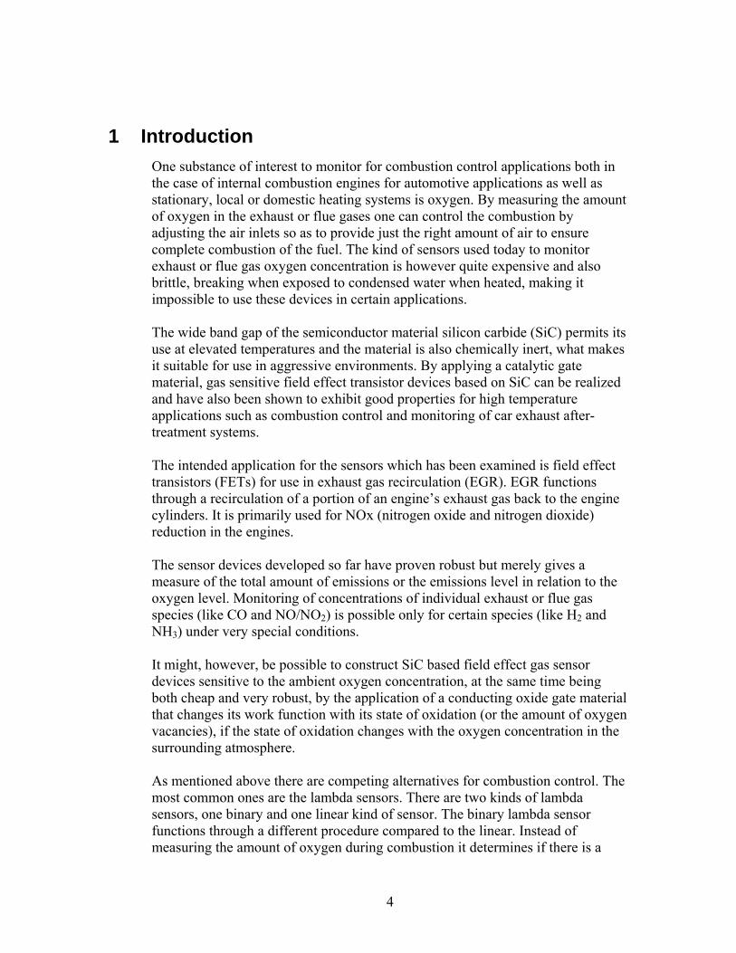
Resistance Measurements on Gas Exposure If a resistance measurement is being performed, a current gets driven through the device using Labview with the NST Senstool application on the computer. This will heat the device to appropriate temperature. After this an I-V measurement is performed using Labview with the NST Senstool application. Gas is driven through the chambers and the output from the devices gets collected. The output consists of the voltage change needed in order to keep a constant current. These types of measurements were performed for the Schottky devices.
I/V-characteristics MISiCFET 25 nm Pt at 225
-0,05
0
0,05
0,1
0,15
0,2
0,25
0,3
0,35
0 1 2 3 4 5 6 7 8 9 10Voltage [ V ]
Current [ mA ]
10% O2 in N2
250 ppm NH3 in 10% O2 in N2
10% O2 in N2 ΔV
Figure 5.3.2 I-V characteristics of a field effect MISiCFET
device. An I-V curve shows how the current changes with the applied voltage. The shift between the two lines in the diagram takes place when introducing 250ppm NH3 to the background gas of 10% O2 in N2 [5]
24
6 Results What follows is the description of each device that has been tested. The theory behind each device will be presented, as well as details of the processing and the results from the measurements. Each device has been tested for its response to oxygen as well as for other gases that are present in exhaust or flue gases. The devices have been tested at several temperatures, ranging from 100°C to 500°C, but only the temperatures which gave the best output is presented in the diagrams.
6.1 IrO2/MgO Capacitor
Theory IrO2 (Iridium oxide) has been found to be sensitive towards oxygen by other researchers ([10], [11]). However, it has also shown cross-sensitivity towards gases which are present during combustion. The hope was to use MgO (Magnesium oxide) to decrease or diminish this cross-sensitivity.
Processing Details For these devices an extra insulating layer of MgO (magnesia) has been evaporated on top of the silicon oxide (SiO2) to a total thickness of approximately 80 nm and annealed in oxygen ambient at 500°C. The Ir contacts have been created by sputter deposition of Ir through a shadow mask at a background Ar pressure of 50 mTorr and oxidization at 500 °C in oxygen during 16 hours. This was made in order to create a surface Iridium oxide. Bonding pads have been formed through evaporation of 50 Å Cr + 2500 Å Au through a shadow mask.
25

Oxygen Response
mV Figure 6.1.1 Diagram showing output in voltage towards time,
from an IrO2/MgO capacitor exposed to pulses of 0.5% to 15% oxygen at a temperature of 300 °C. There were 5 minutes for each pulse followed by 5 minutes of recovering in nitrogen background gas
As seen in figure 6.1.1 there is not much response for this sensor towards oxygen. It was also found that the disturbance level was very high and the sensor output very noisy. This was for example observed by the fact that many devices had several baselines in its measurement output, i.e. several similar lines of output with various displacements for the same sensor and at the same time. These sensors gave small response towards oxygen, with the size of the response close to the disturbance level.
26
Cross Sensitivity
CO Propene mV
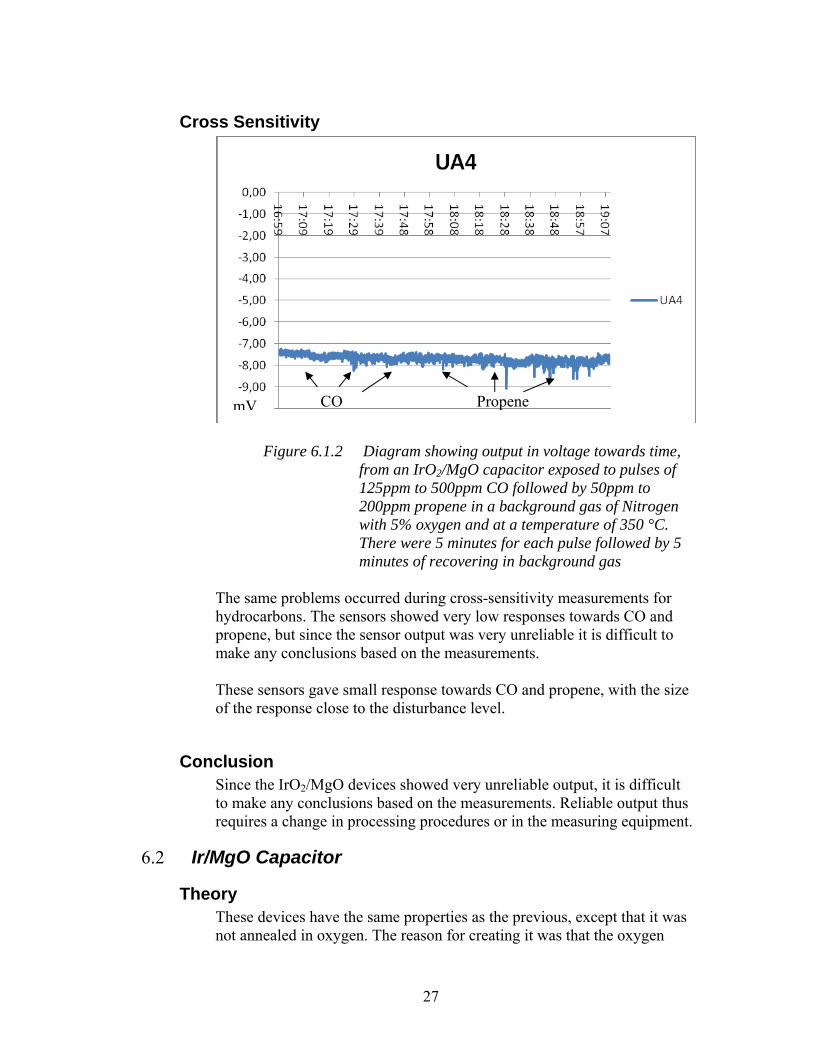
Figure 6.1.2 Diagram showing output in voltage towards time,
from an IrO2/MgO capacitor exposed to pulses of 125ppm to 500ppm CO followed by 50ppm to 200ppm propene in a background gas of Nitrogen with 5% oxygen and at a temperature of 350 °C. There were 5 minutes for each pulse followed by 5 minutes of recovering in background gas
The same problems occurred during cross-sensitivity measurements for hydrocarbons. The sensors showed very low responses towards CO and propene, but since the sensor output was very unreliable it is difficult to make any conclusions based on the measurements. These sensors gave small response towards CO and propene, with the size of the response close to the disturbance level.
Conclusion Since the IrO2/MgO devices showed very unreliable output, it is difficult to make any conclusions based on the measurements. Reliable output thus requires a change in processing procedures or in the measuring equipment.
6.2 Ir/MgO Capacitor
Theory These devices have the same properties as the previous, except that it was not annealed in oxygen. The reason for creating it was that the oxygen
27
annealing could have a negative effect on the device. It could have been caused by the Iridium being more sensitive towards oxygen then IrO2, or because the annealing required a high temperature, which could restructure the device and make it less usable as a sensor.
Processing Details For these devices an extra insulating layer of MgO (magnesia) has been evaporated on top of the silicon oxide (SiO2) to a total thickness of approximately 80 nm and annealed in oxygen ambient at 500°C. The metal contacts (Ir) have been sputter deposited through a shadow mask at a background Ar pressure of 50 mTorr. Bonding pads have been formed through evaporation of 50 Å Cr + 2500 Å Au through a shadow mask. The difference between this device and the prior is that it has not been annealed/treated in oxygen.
Oxygen Response
mV
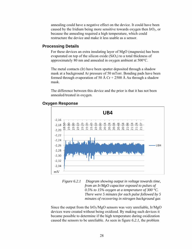
Figure 6.2.1 Diagram showing output in voltage towards time, from an Ir/MgO capacitor exposed to pulses of 0.5% to 15% oxygen at a temperature of 300 °C. There were 5 minutes for each pulse followed by 5 minutes of recovering in nitrogen background gas
Since the output from the IrO2/MgO sensors was very unreliable, Ir/MgO devices were created without being oxidized. By making such devices it became possible to determine if the high temperature during oxidization caused the sensors to be unreliable. As seen in figure 6.2.1, the problem
28
occurred for the Ir/MgO sensors as well. This meant that the cause must be either in the processing of the sensors or in the measuring equipment. These sensors gave small response towards oxygen, with the size of the response close to the noise level.
Cross Sensitivity
CO Propene
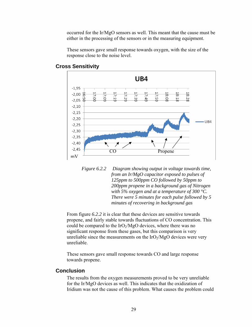
mV Figure 6.2.2 Diagram showing output in voltage towards time,
from an Ir/MgO capacitor exposed to pulses of 125ppm to 500ppm CO followed by 50ppm to 200ppm propene in a background gas of Nitrogen with 5% oxygen and at a temperature of 300 °C. There were 5 minutes for each pulse followed by 5 minutes of recovering in background gas
From figure 6.2.2 it is clear that these devices are sensitive towards propene, and fairly stable towards fluctuations of CO concentration. This could be compared to the IrO2/MgO devices, where there was no significant response from these gases, but this comparison is very unreliable since the measurements on the IrO2/MgO devices were very unreliable. These sensors gave small response towards CO and large response towards propene.
Conclusion The results from the oxygen measurements proved to be very unreliable for the Ir/MgO devices as well. This indicates that the oxidization of Iridium was not the cause of this problem. What causes the problem could
29

be either processing procedures or problems with the measuring equipment.
6.3 Ir/SiO2 Capacitor
Theory In order to compare the effect of MgO (Magnesium oxide) on the previous devices, this similar device was created. The only difference between the Ir/MgO device and the Ir/SiO2 is that the latter is lacking the layer of magnesium oxide.
Processing Details These devices are lacking the insulating layer of MgO (magnesia) as compared to the previous devices. Otherwise it has been treated in the same manner and the Ir (Iridium) is not treated in oxygen. The metal contacts (Pt and Ir) have been sputter deposited through a shadow mask at a background Ar pressure of 50 mTorr. Bonding pads have been formed through evaporation of 50 Å Cr + 2500 Å Au through a shadow mask. It has not been annealed/treated in oxygen.
Oxygen Response
mV Figure 6.3.1 Diagram showing output in voltage towards time,
from an Ir/SiO2 capacitor exposed to pulses of 0.5% to 15% oxygen at a temperature of 300 °C. There were 5 minutes for each pulse and 5 minutes of recovering in nitrogen background gas
30
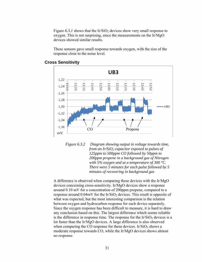
Figure 6.3.1 shows that the Ir/SiO2 devices show very small response to oxygen. This is not surprising, since the measurements on the Ir/MgO devices showed similar results. These sensors gave small response towards oxygen, with the size of the response close to the noise level.
Cross Sensitivity
CO Propene mV
Figure 6.3.2 Diagram showing output in voltage towards time,
from an Ir/SiO2 capacitor exposed to pulses of 125ppm to 500ppm CO followed by 50ppm to 200ppm propene in a background gas of Nitrogen with 5% oxygen and at a temperature of 300 °C. There were 5 minutes for each pulse followed by 5 minutes of recovering in background gas
A difference is observed when comparing these devices with the Ir/MgO devices concerning cross-sensitivity. Ir/MgO devices show a response around 0.10 mV for a concentration of 200ppm propene, compared to a response around 0.04mV for the Ir/SiO2 devices. This result is opposite of what was expected, but the most interesting comparison is the relation between oxygen and hydrocarbon response for each device separately. Since the oxygen response has been difficult to measure, it is hard to draw any conclusion based on this. The largest difference which seems reliable is the difference in response time. The response for the Ir/SiO2 devices is a lot faster than the Ir/MgO devices. A large difference is also observed when comparing the CO response for these devices. Ir/SiO2 shows a moderate response towards CO, while the Ir/MgO devices shows almost no response.
31
These sensors gave moderate response towards CO and large response towards propene.
Conclusion When performing measurements on these devices it was observed that it had only one baseline. The problem which occurred for the previous devises is thus eliminated. Nonetheless, the Ir/SiO2 devices showed a very small response towards oxygen which indicates that Iridium in itself is a fairly poor sensor towards oxygen.
6.4 LaF3/SiO2 Schottky diode
Theory LaF3 (Lanthanium Floride) has also been shown to give response towards oxygen by other researchers, and at very low temperatures ([14], [15]). The goal with creating a Schottky device was to determine if LaF3 was a good sensor towards oxygen, and if it was cross-sensitive to other gases which are present during combustion.
Processing Details The oxide in the gate area has been removed by HF etching followed by 10 min of ozone treatment, resulting in a 1 nm thick native oxide on the surface of the SiC substrate. A 5 nm thick LaF3 film was evaporated through a shadow mask on top of the etched oxide areas. The metal contacts have been evaporated on top of the LaF3 to a thickness of 25 nm (porous film) through a shadow mask. Bonding pads have been formed through evaporation of 50 Å Cr + 2500 Å Au through a shadow mask.
32

Oxygen Response
µV
Figure 6.4.1 Diagram showing output, time and current, from
an LaF3/SiO2 Schottky diode exposed to pulses of 10% to 1% oxygen at a temperature of 300 °C. There were 5 minutes for each pulse followed by 5 minutes of recovering in nitrogen background gas
The measurements on the LaF3 Schottky devices proved to be very clear and reliable as seen in figure 6.4.1, almost every sensor gives a good response towards oxygen. The best sensor gave a response of 0,1mV to an oxygen concentration of 10%. These sensors gave small response towards oxygen.
33

Cross Sensitivity
Figure 6.4.2 Diagram showing output, time and current, from
an LaF3/SiO2 Schottky diode exposed to pulses of 200ppm to 1000ppm H2 followed by 500ppm to 125ppm CO followed by 200ppm to 50ppm propene in a background gas of Nitrogen with 5% oxygen and at a temperature of 300 °C. There were 5 minutes for each pulse followed by 5 minutes of recovering in background gas
Figure 6.4.2 shows results for H2 (three pulses), CO and propene, where H2 is normally not a significant compound in exhaust gases. All sensors show response towards hydrogen, but only 2 shows any significant response towards CO and non towards propene In these test results, the response to H2 is presented in addition to CO and propene. The reason for this response to be omitted from the other measurements is that H2 is not a common compound of exhaust gas and thus not interesting for the intended applications. These sensors gave large response towards hydrogen, moderate response toward CO and no response towards propene, but a change in the baselines are noticed.
Conclusion The results show that LaF3 was a very good sensor towards oxygen, and
CO Propene H2 µV
34

the measurements gave very reliable output. It also gave small responses to other gases which are present during combustion and this material could very well be used in a development of an oxygen sensor.
6.5 LaF3/MgO Capacitor
Theory Since LaF3 proved to be a good sensor toward oxygen, but with some cross-sensitivity, the next step was to see if Magnesium oxide could decrease or eliminate the response to the other gases which are present during combustion, in a similar manner as the investigation made for Iridium.
Processing Details For these devices an extra insulating layer of MgO (magnesia) has been evaporated on top of the silicon oxide (SiO2) to a total thickness of approximately 80 nm and annealed in oxygen ambient at 500°C. The metal contacts (Pt and Ir) have been sputter deposited through a shadow mask at a background Ar pressure of 50 mTorr. Bonding pads have been formed through evaporation of 50 Å Cr + 2500 Å Au through a shadow mask. For these devices a 20 nm thick LaF3 film has been evaporated on top of the insulator (SiOx + MgO).
35
Oxygen Response
mV
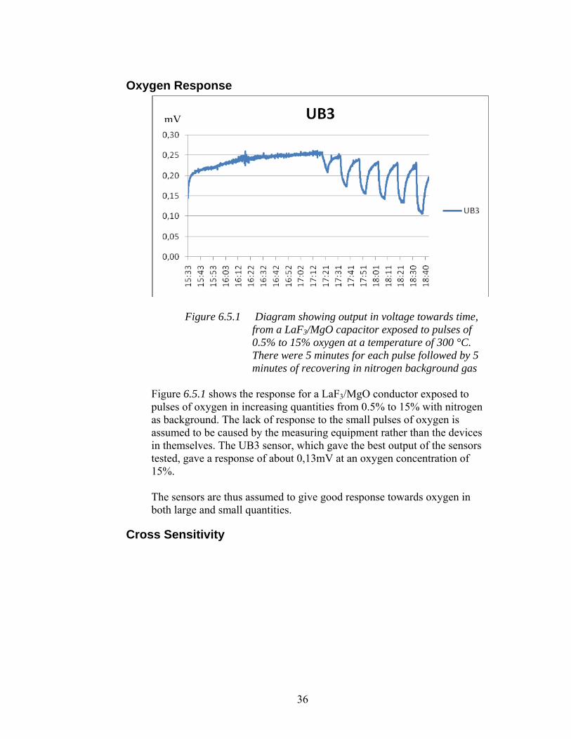
Figure 6.5.1 Diagram showing output in voltage towards time,
from a LaF3/MgO capacitor exposed to pulses of 0.5% to 15% oxygen at a temperature of 300 °C. There were 5 minutes for each pulse followed by 5 minutes of recovering in nitrogen background gas
Figure 6.5.1 shows the response for a LaF3/MgO conductor exposed to pulses of oxygen in increasing quantities from 0.5% to 15% with nitrogen as background. The lack of response to the small pulses of oxygen is assumed to be caused by the measuring equipment rather than the devices in themselves. The UB3 sensor, which gave the best output of the sensors tested, gave a response of about 0,13mV at an oxygen concentration of 15%. The sensors are thus assumed to give good response towards oxygen in both large and small quantities.
Cross Sensitivity
36

mV
CO Propene
Figure 6.5.2 Diagram showing output in voltage towards time,
from a LaF3/MgO capacitor exposed to pulses of 125ppm to 500ppm CO followed by 50ppm to 200ppm propene in a background gas of Nitrogen with 5% oxygen and at a temperature of 300 °C. There were 5 minutes for each pulse followed by 5 minutes of recovering in background gas
When comparing figures 7.4.2 and 7.5.2 it is observed that the CO response is almost eliminated when using MgO as base, and the propene exposure does not increase the basline. The UB3 sensor gave a response of about 0,015mV at a propene concentration of 200ppm and about 0,025mV at a CO concentration of 500ppm. These sensors gave small response towards CO and propene.
Conclusion Measurements made on the LaF3/MgO devices show that the introduction of MgO as substrate makes the sensors less affected by fluctuations of CO concentrations in particular. It is still sensitive and gives good output towards oxygen, which make these devices very good sensors towards oxygen in exhaust gases.
7 Discussion There are some procedures in the thesis work which could be improved further. A detailed schedule for measurements would for example have helped on several occasions. Another improvement could have been to plan ahead on the measurements, for example to perform all measurements of a given temperature
37

subsequent of each other. This would prevent restructuring at high temperature followed by measurements at low temperature, as was the case in several of the measurements performed. In some of the measurements the devices gave a very slow response or a slow recovering. This caused the sensors not to recover in between pulses. Those devices could have been examined more thoroughly with more time for each pulse. A similar problem which was encountered for most of the devices was the problem with drift. Those devices could also have been examined more thoroughly but by the introduction of a very long introductory pulse.
38

8 Error Sources There are also some factors which have an effect on the devices but for which it was impossible to have any influence. One is the limitation on the processing procedures which are the result of limited processing equipment at LiU University. Another is the gas regulators, which seem to function poorly at low pressures.
39

9 Summary
9.1 IrO2 It was very difficult to make any conclusions based on the measurements on the IrO2 devices. Changes have to be made in order to get reliable output such as a change in processing procedures or measuring equipment.
9.2 Ir Measurements on the Ir devices gave very small responses towards oxygen, not far from the disturbance levels. This concludes that the Ir devices would function poorly as an oxygen sensor. This result also hints that a functioning IrO2 device would work rather poorly, though this is only a presumption.
9.3 LaF3 The LaF3 devices proved to be very good sensors towards oxygen, though with some cross sensitivity to propene in particular.
9.4 MgO It was not possible to draw any conclusion on the effect of MgO on the Ir devices, since the output from those was very unreliable. It was however possible to observe a difference in the propene level of response for the LaF3 devices. LaF3 on SiO2 gave a small response to propene, which became even smaller when introducing MgO as substrate material. The largest effect on introducing MgO was observed when comparing the LaF3/SiO2 with the LaF3/MgO devices concerning response towards CO. The LaF3/MgO devices showed a lot smaller response towards this gas.
9.5 Best Material Analyzed The conclusion from these measurements is that the LaF3/MgO/SiO2/SiC device gives the best results for response to oxygen and low cross-sensitivity to other gases which are compounds in exhaust or flue gases. This capacitor could very well be used as an oxygen sensor, and the material combination should be tested in a transistor device.
9.6 Design Proposal The design proposal consisted of a conductor made with Gd2O3 as substrate material and CeGd0.2O2 as top sensing material. The design was not implemented due to problems associated with its fabrication.
40

10 Future Work There is a lot of work made in this thesis project that could be examined more thoroughly. One major problem occurred when performing measurements on the Iridium devices. The output showed several baselines and was in general very unreliable. The cause of this was not discovered but there are some ways to examine the problem. One is simply to change into another measuring system and another way is to sputter the Iridium oxide instantaneously, compared to sputtering Iridium followed by an annealing in oxygen at high temperature. This would rule out the possibility of the sensor being restructured during the annealing. SEM, Scanning Electron Microscope, was never utilized in the thesis work. But this is a very powerful tool for discovering defects on the devices. It can be used for examining the devices which were not functioning Another topic which could be examined further is of course the design proposal which was made in the early stages of the thesis project. This design could be compared to a similar device which utilize the same sensor material, CGO20, but where the layer of Gd2O3 is omitted.
41

11 Acknowledgments I wish to give special thanks to my supervisor Mike Andersson, and my examiner Anita Lloyd Spets. I want to thank all the people on the IFM institution who have helped and given their support and also, my family.
42

12 References Chapter 4
[1] High Temperature SiC-FET Chemical Gas Sensors Advances in Silicon Carbide Processing and Applications, ISBN-13: 978-1580537407, editors S. E. Saddow and A. Agarwal, Artech House, Boston, USA, Chapter 2 (2004), pp 29-67 - A. Lloyd Spetz, S. Nakagomi, S. Savage
[2] Gas sensor device based on Metal-Insulator-Silicon carbide-Junction-Field Effect-Transistor Encyclopedia of Sensors, editors C. A. Grimes and E. C. Dickey, American Scientific Publishers, Stevenson Ranch, Ca, USA, Volume 4 (2006), pp. 171-192 - Shinji Nakagomi, Susan Savage, Anita Lloyd Spetz
[3] Cosputtered Metal and SiO2 Layers for Use in Thick-Film MISiC NH3 Sensors IEEE Sensors Journal, 6, 4 (2006), pp 887-897 - H. Wingbrant, M. Persson, A. E. Åbom, M. Eriksson, B. Andersson, S. Simko, D. J. Kubinski, J. H. Visser, A. Lloyd Spetz
[4] Studies of MISiC-FET Sensors for Car Exhaust Monitoring Linköping Sudies in Science and Technology, PhD Thesis No. 931. ( April 2005) - Helena Wingbrant
[5] SiC based Field Effect Sensor and Sensor Systems for Combustion Control Applications Linköping Sudies in Science and Technology, PhD Thesis No. 1077. (March 23, 2007)
Chapter 5
[6] Substrate effects on the Oxygen Gas Sensing Properties of SnO2/TiO2 thin Films Applied Surface Science, Volume 253, Issue 4 (2006), pp. 1889-1897. - Hsiao-Ching Lee, Weng-Sing Hwang
43
[7] Melting Points, Spectral Reflectivity, and Emissivity of Semitransparent Ceramic Materials International Journal of Thermophysics, Volume 20, Number 6 (1999), pp. 1801-1809(9) - T.P. Salikhov, V.V. Kan
[8] Properties of Thermal Gadolinium Oxide Films on Silicon Japanese Journal of Applied Physics, Volume 44, Issue 5A (2005), pp. 3205 - Hong-Hsi Ko, Liann-Be Chang, Ming-Jer Jeng, Ping-Yu Kuei, Kuo-Yang Horng
[9] Band Offsets of High K Gate Oxides on III-V Semiconductors Journal of Applied Physics, Volume 100, Issue 1 (2006), pp. 014111-014111-8 - J. Robertson, B. Falabretti
Chapter 7
[10] Characteristics of Schottky contacts on n-type 4H-SiC using IrO2 and RuO2 Journal of Applied Physics 94:9 (2003), pp. 6159-6166 - Han S. Y., Lee J-L.
[11] Characteristics of Schottky contacts on n-type 4H-SiC using IrO2 and RuO2 Journal of Applied Physics 94:9 (2003), pp. 6159-6166 Han S. Y., Lee J-L.
[12] Atomic-Scale Structure and Catalytic Reactivity of the RuO2(110) Surface Science 287 (2000), pp. 1407-1409 Over H., Kim Y. D., Seitsonen A. P., Wendt S., Schmid M., Varga P., Morgante A., Ertl G.
[13] Nanocrystalline ruthenium oxide and ruthenium in sensing applications - an experimental and theoretical study Journal of nanoparticle research 8:6 (2006), pp.899-910 Salomonsson A, Petoral R. M., Uvdal K., Aulin C., Käll P-O., Ojamäe L., Strand M., Sanati M., Lloyd Spetz A.
44
45
[14] Influence of the LaF3/ metal interface on the properties of a low temperature oxygen sensor Sensors and Actuators B 15-16 (1993), pp. 252-255 Krause S., Krankenhagen R., Moritz W., Grohmann I., Unger W., Gross T., Lippitz A.
[15] Improved long term stability for an LaF3 based oxygen sensor Sensors and Actuators B 18-19 (1994), pp. 148-154 Krause S., Moritz W., Grohmann I.