processing and properties of carbon nanotube-copper composites
TRANSCRIPT

-otl
aA
DD
13/
910
2
+bfcei
a*GMFTSH
9 NBSI 1-5248-06-259-879 )detnirp( NBSI 8-6248-06-259-879 )fdp( NSSI 4394-9971 )detnirp( NSSI 2494-9971 )fdp(
ytisrevinU otlaA
gnireenignE lacimehC fo loohcS gnireenignE lacigrullateM dna lacimehC fo tnemtrapeD
if.otlaa.www
+ SSENISUB YMONOCE
+ TRA
+ NGISED ERUTCETIHCRA
+ ECNEICS
YGOLONHCET
REVOSSORC
LAROTCOD SNOITATRESSID
alu
nna
H ok
kiM-
yryP
set
isop
moc
repp
oc-e
buto
nan
nobr
ac f
o se
itre
porp
dna
gni
ssec
orP
yti
srev
in
U otl
aA
9102
gnireenignE lacigrullateM dna lacimehC fo tnemtrapeD
seitreporp dna gnissecorP reppoc-ebutonan nobrac fo
setisopmoc
alunnaH okkiM-yryP
LAROTCOD SNOITATRESSID

seires noitacilbup ytisrevinU otlaASNOITATRESSID LAROTCOD 13 / 9102
nobrac fo seitreporp dna gnissecorP setisopmoc reppoc-ebutonan
alunnaH okkiM-yryP
fo rotcoD fo eerged eht rof detelpmoc noitatressid larotcod A eht fo noissimrep eht htiw ,dednefed eb ot )ygolonhceT( ecneicS
cilbup a ta ,gnireenignE lacimehC fo loohcS ytisrevinU otlaA 8 no loohcs eht fo oirotiduA llah erutcel eht ta dleh noitanimaxe
.21 ta 9102 hcraM
ytisrevinU otlaA gnireenignE lacimehC fo loohcS
gnireenignE lacigrullateM dna lacimehC fo tnemtrapeD noisorroC dna ygrullatemordyH

Printed matter4041-0619
NO
RDIC
SWAN ECOLABE
L
Printed matter1234 5678
rosseforp gnisivrepuS dnalniF ,ytisrevinU otlaA ,mörtsdnuL iraM rosseforP
rosivda sisehT
dnalniF ,ytisrevinU otlaA ,aamorA iraJ tnecoD
srenimaxe yranimilerP yragnuH ,)SAH( secneicS fo ymedacA nairagnuH ,iynokaB ermI sutiremE rosseforP
niapS ,)MINEC( sacigrulateM senoicagitsevnI eD lanoicaN ortneC ,návlaG solraC nauJ .rD
tnenoppO nedewS ,nedewS fo setutitsnI hcraeseR ESIR ,rensieL reteP tnecoD
seires noitacilbup ytisrevinU otlaASNOITATRESSID LAROTCOD 13 / 9102
© 9102 alunnaH okkiM-yryP
NBSI 1-5248-06-259-879 )detnirp( NBSI 8-6248-06-259-879 )fdp( NSSI 4394-9971 )detnirp( NSSI 2494-9971 )fdp(
:NBSI:NRU/if.nru//:ptth 8-6248-06-259-879
yO aifarginU iknisleH 9102
dnalniF

tcartsbA otlaA 67000-IF ,00011 xoB .O.P ,ytisrevinU otlaA if.otlaa.www
rohtuA alunnaH okkiM-yryP
noitatressid larotcod eht fo emaN setisopmoc reppoc-ebutonan nobrac fo seitreporp dna gnissecorP
rehsilbuP gnireenignE lacimehC fo loohcS
tinU gnireenignE lacigrullateM dna lacimehC fo tnemtrapeD
seireS seires noitacilbup ytisrevinU otlaA SNOITATRESSID LAROTCOD 13 / 9102
hcraeser fo dleiF yrtsimehcortcelE
dettimbus tpircsunaM 8102 rebmeceD 01 ecnefed eht fo etaD 9102 hcraM 8
)etad( detnarg hsilbup ot noissimreP 9102 yraunaJ 32 egaugnaL hsilgnE
hpargonoM noitatressid elcitrA noitatressid yassE
tcartsbAdna lamreht ,lacinahcem yranidroartxe tibihxe )TNC( sebutonan nobrac laudividni enitsirP
etuor enO .snoitacilppa lacitcarp otni etalsnart ot tlucfifid neeb evah hcihw ,seitreporp lacirtcele htiw sebutonan nobrac enibmoc ot si elacs regral a no seitreporp lairetam devorpmi gniniatbo ot noitareneg wen a sa desoporp neeb evah setisopmoc hcuS .reppoc ,lairetam rotcudnoc lanoitidart a gnivorpmi rof laitnetop rieht ot eud srotcudnoc reppoc lanoitidart ecalper ot slairetam rotcudnoc fo
,yticapac gniyrrac tnerruc ,ytivitcudnoc lacirtcele cfiiceps sa hcus ,reppoc fo seitreporp suoirav .ytisned cfiiceps dna seitreporp lacinahcem
nobrac edamerp otno reppoc fo ssecorp noitisoped lacimehcortcele eht no sesucof siseht sihT etahplus reppoc suoeuqa morf ,mlfi dna nray ,rebfi TNC a sa hcus ,serutcurtsorcam ebutonan
-TNC detisopedortcele eht fo ytivitcudnoc lacirtcele cfiiceps dna erutcurtsorcim ehT .setylortcele .seriw uC-TNC fo seitreporp noisorroc eht sa llew sa detagitsevni osla era selpmas uC
yticibohpordyh ,ytivitcudnoc lacirtcele wol sa hcus ,serutcurtsorcam TNC enitsirp fo seitreporp ehT .ylbaredisnoc ssecorp noitisoped lacimehcortcele eht tceffa ot dnuof era seitirupmi fo ecnetsixe dna
noitisoped lacimehcortcele eht ,serutcurtsorcam TNC fo ytivitcudnoc lacirtcele wol eht ot euD erom sedivorp tisoped reppoc eht sa rehtruf sdeecorp dna tcatnoc lacirtcele eht ot tsesolc snigeb
TNC fo edisni eht no uC fo noitartenep fo eerged ehT .edortcele gnikrow eht ot ytivitcudnoc TNC ytisorop rehgih htiw ,lairetam TNC fo ytisorop eht no tnedneped eb ot dnuof saw lairetam
.edisni eht no tisoped ot reisae gnieb serutcurtsorcameht fo esnopser lacimehcortcele eht evorpmi ot redro ni deilppa erew stnemtaert-erp evitadixO
-ortcele dna tnemtaert taeh ,stnemtaert noitazilanoitcnuf eht fo eerged ehT .smlfi TNC deyolpmesmlfi TNC fo ytivitca lacimehcortcele ehT .sretemarap deyolpme eht yb dellortnoc erew ,noitadixo .devomer erew selcitrap nobrac suohproma derisednu eht elihw ,decnahne ylbaredisnoc eb dluoc
krowten TNC eht edisni noitisoped delbane hcihw ,cilihpordyh emaceb mlfi TNC eht ,noitidda nI .mlfi eht fo ecafrus eht no tsuj ton dna
lacirtcele cfiiceps rieht tceffa ot dnuof erew snray dna srebfi uC-TNC fo erutcurtsorcim ehT erehw ,srebfi uC-TNC fo ytivitcudnoc cfiiceps eht ,sebutonan fo tnuoma nevig yna tA .ytivitcudnoc
nray uC-TNC a rof taht naht rellams si xirtam reppoc a edisni deddebme era sebutonan nobrac ot eud eb ot demussa si sihT .eroc ebutonan nobrac eht gnidnuorrus gniddalc reppoc a ylno htiw
ebutonan-ebutonan eht dna sevlesmeht sebutonan devruc eht fo ecnatsiser lacirtcele hgih eht .eriw eht fo edisni eht no snoitcnuj
gnitsac yb decudorp sebutonan llawitlum % tw 50.0 htiw seriw uC-TNC fo seitreporp noisorroc ehT eht edisni sebutonan fo noitartnecnoc llams eht fo tceffe ehT .detagitsevni osla erew gniward dna sTNC neewteb noisorroc cinavlag oN .ylthgils etar noisorroc eht ecuder ot nwohs saw xirtam reppoc .secafrus elpmas eht morf ro stnemerusaem yb devresbo eb dluoc xirtam uC gnidnuorrus eht dna
sdrowyeK noitisopedortcele ,etisopmoc ,reppoc ,ebutonan nobrac
)detnirp( NBSI 1-5248-06-259-879 )fdp( NBSI 8-6248-06-259-879
)detnirp( NSSI 4394-9971 )fdp( NSSI 2494-9971
rehsilbup fo noitacoL iknisleH gnitnirp fo noitacoL iknisleH raeY 9102
segaP 321 nru :NBSI:NRU/fi.nru//:ptth 8-6248-06-259-879


ämletsiviiT otlaA 67000 ,00011 LP ,otsipoily-otlaA if.otlaa.www
äjikeT alunnaH okkiM-yryP
imin najriksötiäV teduusianimo aj sutsimlav neittiisopmokirapuk-iktuponaniliiH
ajisiakluJ uluokaekrok nakiinket naimeK
ökkiskY sotial naigrullatem aj nakiinket naimeK
ajraS seires noitacilbup ytisrevinU otlaA SNOITATRESSID LAROTCOD 13 / 9102
alasumiktuT aimekökhäS
mvp neskutiojrikisäK 8102.21.01 äviäpsötiäV 9102.30.80
äviäpsimätnöym navulusiakluJ 9102.10.32 ileiK itnalgnE
aifargonoM ajriksötiävilekkitrA ajriksötiäveessE
ämletsiviiTtesiökhäs aj tesimret ,tesinaakem tävyh navattamouh no alliktuponaniliih ällisiättiskY
no assavaakattim assammeruus aiskuusianimo ätiän äätnydöyh oniek iskY .teduusianimo atsialläT .assnak nirapuk aiktuponaniliih näätetsidhy assoj ,ilaairetamittiisopmok aatsimlav
iov ittiisopmok aksok ,aimithojirapuk äisietnirep naamaavrok uttetodhe no ailaairetam netuk ,aiskuusianimo ätiekrät ellilaairetamnidhoj atiesu aatnarap anutletsakrat itsesitteeroet
.aoniap nes äätnevek äkes äykykotnaknarriv aj attuuvathoj ätsiökhäsatsesiajhopisev aissesorpsutsoasökhäs nirapuk aiktut no aneettiovat najriksötiäv nämäT
,elliudiukiktuponaniliih netuk ,elliesiirtamiktuponaniliih ellisialire ätsityylortkeleittaaflusirapuk nesiökhäs nesiahla neisiirtamiktuponaniliiH .elliovlakiktuponaniliih aj elliognaliktuponaniliih sammeuak eenete aj aitkatnok ätsiökhäs ätlehäl aakla issesorpsutsoasökhäs aikat neduuvathoj
nisiirtamiktuponan uvsak nirapuK .attuuvathojnökhäs nidortkeleöyt asseatnarap nirapuk navavsak .suusiokouh nisiirtam no ipmeruus ätim ,aapmopleh ätis no elläsis
attuusiviitka atsillaimekökhäs neimlfiiktuponaniliih tavisnarap tylettisäkise tavattepaH ätte ällylettisäköpmäl äkes adiollortnok niitiov attuuvhav nylettisäksutepaH .itsavattamouh
,iovsak suusiviitka nenillaimekökhäs nilaairetam nuk allamaS .alleskutepah allesillaimekökhäs ,iovsak syysilifiordyh nilaairetam iskäsiL .atlannip nilaairetam siop iuttepah iliih nenfiroma söym
.iskesillodham ilut elläsis nimlfi sutsoasökhäs nirapuk niollojnuutiosilamron allassam nediin ittukiav ennekarorkim nejoknal aj nejutiukirapuk-iktuponaniliiH suuvathoj nenfiiseps nejutiukirapuk-iktuponaniliiH .)suuvathoj nenfiiseps( nyykykothoj neesiökhäs
niav iuttionnip irapuk assiognaL .nejoknalirapuk-iktuponaniliih neivaatsav niuk ,ipmeneip ilo assietnekarutiuk nuk ,neettionnipirapuk navathoj nivyh naathup neatsodoum ellääp nisiirtam
attuuvathoj ätsfiiseps nejutiuk niölläT .elläsis nisiirtam niiläv neiktuponan söym iytnidy irapuk .suuvathojsianimo okkieh äkes teskutsavitkatnok tesiläv neiktuponan söym isnekieh
aiktuponaniliih aittnesorponiap 50.0 nejyttedev iskiognal aj nejuttelav söym niittiktut ässöyT ilo sueponoisoorrok nejoknalittiisopmoK .aiskuusianimo-oisoorrok nejoknalirapuk neivätläsis
ie atsoisoorrok atsesinaavlag ätiettiiV .ipmeneip airapuk atsadhup nameih alliedotem alliutiktut .allamiktut ajotnipoisoorrok äkie ällimletenem allisillaimekökhäs uttedot
tanasniavA sutsoasökhäs ,ittiisopmok ,irapuk ,iktuponaniliih
)utteniap( NBSI 1-5248-06-259-879 )fdp( NBSI 8-6248-06-259-879
)utteniap( NSSI 4394-9971 )fdp( NSSI 2494-9971
akkiapusiakluJ iknisleH akkiaponiaP iknisleH isouV 9102
äräämuviS 321 nru :NBSI:NRU/fi.nru//:ptth 8-6248-06-259-879


i
Acknowledgements
The research work presented in this thesis was conducted at Aalto University during 2014-2018. The majority of the work was carried out in the School of Chemical Engineering, De-partment of Chemical and Metallurgical Engineering, Department of Materials Science and Engineering and at Micronova Nanofabrication Center in Espoo. Part of the experimental work was carried out in University of Cambridge, UK and at Nexans Research Center Lens, France, which are greatly acknowledged. The work was funded by the EU FP7 Ultrawire project and the NoWaste project. Walter Ahlström foundation is also greatly acknowledged.
I would like to thank my supervisor Professor Mari Lundström for her continuing support and advice throughout my doctoral studies. Mari taught me the value of working efficiently and how to express my ideas in a concise way. I would also like to thank Professor Emeritus Olof Forsén, who introduced me to the world of making science back when I started in the Ultrawire project. His support and encouragement has made my journey a little more fun and memorable. I would like to express my deep gratitude to my advisor Docent Jari Aro-maa, who taught me the importance of combining theoretical understanding with rigorous experimental work. I have thoroughly enjoyed and greatly benefitted from the scientific dis-cussions we have had over the years.
I consider myself lucky for having had Dr. Dawid Janas as a collaborator in my research. I wish to thank Dawid for providing me the crucial carbon nanotube raw material and further, for his valuable support throughout my studies. I also want to thank my other co-authors, in alphabetical order, Minttu Junnila, Krzysztof Koziol, Sanni Lassila, Nicolas Masquelier, Antti Peltonen and Ben Wilson. Many thanks to Ben for helping me put things into perspec-tive when I have needed it.
I also want to thank all my colleagues and friends at the research group of Hydrometallurgy and Corrosion. I feel grateful for having done my studies surrounded by so many unique and bright individuals. I want to thank especially Antti Porvali, Heini Elomaa, Maria Lei-kola, Arman Dastpak, Sipi Seisko, Zulin Wang, Arif Aji, Kamran Khalid, Taina Kalliomäki and Petteri Halli. Sincere thanks to all my other friends, especially Ville Touronen, for all the good times spent together throughout the years.

ii
I never actually seriously considered pursuing a doctoral degree before the opportunity pre-sented itself. But I’m so glad I did. I want to thank my parents, Simo-Pekka and Leena, for always encouraging me to further educate myself. Thanks for always having the time to share your advice, even if I didn’t think I needed it. I want to thank my sisters Laura and Krista and my brother-in-law Risto, who have always supported me (and kept me grounded!) in my endeavours. Lukas and Tomas, you are still too young to read this, but I’m so happy for having such awesome nephews in my life. Finally, thank you Tuuli for always being there for me and seeing the best in me. Espoo, February 2019 Pyry-Mikko Hannula

iii
Contents
List of abbreviations and symbols ............................................................ v
List of publications ................................................................................ vii
Author’s contribution ........................................................................... viii
1. Introduction .................................................................................. 1
1.1 Background ................................................................................ 1
1.2 Objectives and scope ................................................................. 2
1.3 Structure of this thesis .............................................................. 5
2. Theoretical background ................................................................ 6
2.1 Fundamental properties of CNTs and Cu ................................. 6
2.2 Electrodeposition of copper ..................................................... 11
2.3 Other production methods of CNT- Cu composites ................ 16
2.4 Properties of CNT-Cu composites ........................................... 17
2.4.1 Structure of CNT-Cu composites ......................................... 17
2.4.2 Mechanical properties of CNT-Cu composites ................... 20
2.4.3 Electrical and thermal properties of CNT-Cu composites .. 24
2.4.4 Corrosion properties of carbon-Cu composites ................... 31
3. Experimental .............................................................................. 35
3.1 CNT raw material preparation ................................................ 35
3.2 CNT material characterization ............................................... 36
3.3 Electrochemical cell set up and methods ................................37
3.4 Oxidation of CNT material ...................................................... 39
3.5 Specific electrical conductivity ............................................... 39
3.6 Corrosion behaviour ............................................................... 39
3.7 Casting and drawing to produce CNT-Cu wire ........................ 41
4. Results and discussion ............................................................... 42
4.1 Characteristics of employed CNT material ............................. 42
4.2 Electrochemical deposition process on pristine CNT macrostructures 45
4.3 Electrochemical deposition process on functionalized CNT macrostructures 54

iv
4.4 Specific electrical conductivity of CNT-Cu composites by electrodeposition 56
4.5 Corrosion properties of CNT-Cu composites by casting and drawing 58
5. Conclusions ................................................................................. 61
References .............................................................................................. 63

v
List of abbreviations and symbols
CNT Carbon nanotube
CVD Chemical vapour deposition
CTE Coefficient of thermal expansion (ppm K-1)
D Diameter
DWNT Double-walled carbon nanotube
E Young’s modulus
ED Electrodeposition
FIB Focused ion beam
FTIR Fourier-transfrom infrared spectroscopy
Gcrit Critical free energy barrier
IACS International annealed copper standard
icorr Corrosion current density (mA cm-2)
IC Integrated circuit
H Hardness (GPa)
J Nucleation rate (nuclei cm-2s-1)
Jmax Ampacity (A cm-2)
MWNT Multi-walled carbon nanotube
PVD Physical vapour deposition
SCE Standard calomel electrode
SCCM Standard cubic centimeters per minute
SEM Scanning electron microscope
SPS Spark plasma sintering
SWNT Single-walled carbon nanotube
TCR Temperature coefficient of resistance (10-3 K-1)

vi
TDC Three-dimensional crystallites
ULSI Ultra large-scale integration
UTS Ultimate tensile strength (GPa)
YS Yield strength (MPa)
Electrical conductivity (MSm-1)
Specific electrical conductivity (MSm-1g-1cm3)
ρ Density (g cm-3)
κ Thermal conductivity (Wm-1K-1)

vii
List of publications
This doctoral thesis consists of a summary and of the following publications, which are re-ferred to in the text by their respective roman numerals:
I Pyry-Mikko Hannula, Antti Peltonen, Jari Aromaa, Dawid Janas, Mari Lundström, Benjamin P. Wilson, Krzysztof Koziol, Olof Forsén, 2016. Carbon nanotube- copper composites by electrodeposition on carbon nanotube fibers. Elsevier. Carbon, volume 107, pages 281-287. ISSN: 0008-6223. DOI: 10.1016/j.carbon.2016.06.008.
II Pyry-Mikko Hannula, Minttu Junnila, Dawid Janas, Jari Aromaa, Olof Forsén, Mari Lundström, 2018. Carbon Nanotube Fiber Pretreatments for Electrodeposi-tion of Copper. Hindawi. Advances in Materials Science and Engineering, volume 2018, pages 1-8. ISSN: 1687-8442. DOI: 10.1155/2018/3071913.
III Pyry-Mikko Hannula, Jari Aromaa, Wilson, Benjamin P. Wilson, Dawid Janas, Krzysztof Koziol, Olof Forsén, Mari Lundström, 2017. Observations of copper deposition on functionalized carbon nanotube films. Elsevier. Electrochimica Acta, volume 232, pages 495-504. ISSN: 0013-4686. DOI: 10.1016/j.electacta.2017.03.006.
IV Pyry-Mikko Hannula; Nicolas Masquelier, Sanni Lassila, Jari Aromaa, Dawid Ja-nas, Olof Forsén, Mari Lundström, 2018. Corrosion behaviour of cast and de-formed copper-carbon nanotube composite wires in chloride media. Elsevier. Journal of Alloys and Compounds, volume 746, pages 218-226. ISSN: 0925-8388. DOI: 10.1016/j.jallcom.2018.02.289

viii
Author’s contribution
Publication I: “Carbon nanotube- copper composites by electrodeposition on carbon nanotube fibers” P.H was responsible for the experimental design together with co-authors, performed the experimental work, analyzed the corresponding results and wrote the manuscript under the supervision of J.A, O.F and M.L. The CNT raw material was prepared at University of Cambridge by D.J and K.K. A.P conducted the focused ion beam milling of the samples and the majority of SEM imaging and EDS analysis. B.P Wilson critically reviewed the re-sults and conclusions.
Publication II: “Carbon nanotube fiber pre-treatments for electrodeposition of copper” M.J was responsible for the majority of experimental work, including the pre-treatment of CNT material and EIS measurements under the supervision of P.H and J.A. M.J wrote the initial manuscript under the supervision of P.H, J.A, O.F and M.L. J.A and P.H were re-sponsible for the experimental design together with co-authors. P.H was responsible for the electrochemical deposition of copper on CNT yarn and the specific electrical conduc-tivity measurements along with writing the final manuscript. D.J was responsible for the CNT raw material production at University of Cambridge. Publication III: “Observations of copper deposition on functionalized carbon nanotube films” P.H was responsible for the experimental design together with co-authors, performed the experimental work, analyzed the corresponding results and wrote the manuscript under the supervision of J.A, O.F and M.L. The CNT raw material was prepared at University of Cambridge by D.J and K.K. B.P Wilson critically reviewed the results and conclusions. Publication IV: “Corrosion behaviour of cast and deformed copper- carbon nanotube composite wires in chloride media”
P.H was responsible for the experimental design, analyzed the corresponding results and wrote the manuscript under the supervision of J.A, O.F and M.L. N.M was responsible for producing the carbon nanotube- copper composite samples. S.L performed the majority of the experimental work under supervision of P.H. The CNT raw material was prepared at University of Cambridge by D.J.

1
1. Introduction
1.1 Background
Since the discovery of carbon nanotubes (CNTs) in 1991 by Sumio Iijima, there has been significant research interest in producing, characterizing and applying their extraordinary properties in practical applications. One of the most researched applications of CNTs is in the formation of composites with existing materials, to provide improved material solutions that meet the ever increasing demands of technology (Bakshi et al., 2010; Aryasomayajula & Wolter, 2013).
Copper (Cu) has been traditionally utilized as a conductor material in a plethora of appli-cations, ranging from the very minute microchips of ultralarge-scale integrated (ULSI) de-vices to electrical wirings and along with aluminium, in massive structures for power trans-mission in overhead lines. Copper is also used in electronics as a heat-sink material due to its high thermal conductivity. The use of copper in such a wide range of applications is due to its excellent electrical and good mechanical properties along with a relatively modest price. Nevertheless, there exists a growing demand for improving the properties of copper, for applications in smaller and lighter electronic devices that can withstand harsher operat-ing conditions, such as elevated temperatures and higher current densities.
The miniaturization of electronic devices as predicted by Moore’s law has led to energy localizations in the continuously down-scaled copper interconnections in integrated circuits (ICs). Modern ICs have billions of transistors and other electronic components in an area of ca. 1 cm2. Copper based interconnects between transistors are now considered a bottleneck in the development of smaller components. This is due to the various reliability issues that arise from decreasing the dimensions of copper interconnects, such as increased tempera-tures, electrical resistivity and electromigration (Lin et al., 2018). For instance, the current density in devices has been estimated to already be at the threshold (~ 10 MA cm-2) of what pure Cu is capable of conducting reliably without void formation due to electromigration. The International Technology Roadmap for Semiconductors (2015) suggests carbon nano-tube based materials as one possible solution to these increasingly difficult technical de-mands in interconnects. The need to improve conductor materials is also emphasised by ongoing trends in the de-velopment of, e.g., aerospace and electrical vehicle industries. The amount of copper in an average automobile is up to 22 kg, while fully electrical vehicles contain ca. 83 kg of copper (Copper Development Association, 2018a). A sustainable development of these industries calls for new materials that improve the de-sired property per kilogram of material used, such as electrical conductivity. Such improve-ments would have a direct mitigating effect on the fuel consumption and CO2 emissions

2
from said industries. Furthermore, on a larger scale, as electricity is typically produced cen-tralized, i.e., far away from where it is consumed, the electrical properties of overhead lines dictate the resulting electrical energy losses during power transmission. Currently, ca. 7% of generated electricity in the western world is consumed by resistive losses in the transmis-sion and distribution network before reaching the end user (Razanousky et al., 2012). These global demands for improving conductor materials have acted as the catalysts for this work.
Carbon nanotubes are considered as highly attractive constituents in composite materials due to their low density and exceptional inherent properties. The first to propose CNT based copper composite materials as an alternative to pure copper conductors were Hjortstam et al. (2004). They based their reasoning on promising theoretical calculations of increased CNT-Cu electrical properties that assumed no contact resistance between CNTs and Cu. Various types of carbon nanotube-copper composites have been the subject of experimental research since the early part of the 21st century. The produced composites have been made in a variety of copper and carbon nanotube configurations, where the CNTs are either sur-rounded by a copper matrix, or exist as a separate continuous phase e.g as a coating on copper or vice versa. There are several motivations for combining these materials in differ-ent configurations to produce composites, but the rationale is always in improving some property, which cannot be achieved with pure copper.
The often researched properties in literature for different types of CNT-Cu composites in-clude strength, toughness, fatigue, ductility, corrosion resistance, thermal properties, elec-trical conductivity and current carrying capacity among others. While the production of CNT-Cu composites has been successfully implemented with a wide variety of methods and by different research groups, improvements in composite properties over pure copper have mostly remained elusive despite some encouraging exceptions. To date, the experimentally observed improvements in electrical and thermal properties of CNT-Cu have been more dif-ficult to achieve than advances in mechanical properties. Improvements in mechanical properties beyond pure Cu have been routinely reported, while improvements in various electrical and thermal properties have been more recent. Typically, the majority of improve-ments achieved by high temperature production methods have been in the field of mechan-ical properties and the improvements in electrical and thermal properties have been demon-strated primarily by electrochemical deposition. Among the most exciting results, Subra-maniam et al. (2013, 2014, 2016) showed carbon nanotube-copper composites produced by electrodeposition of copper onto existing CNT macrostructures with superior electrical properties compared with pure Cu, including 26% higher electrical conductivity by weight and 100 times higher ampacity, i.e., current carrying capacity, among other improved elec-trical properties. As such, the research into the production and properties of these exciting composite materials is ongoing with new developments being continuously reported.
1.2 Objectives and scope
On a theoretical level, combining carbon nanotubes (ρ ≈ 1.3 g cm-3) with copper (ρ = 8.96 g cm-3) could offer a new type of composite material with improved properties beyond those found in pure copper. Such conductors could potentially have, e.g., increased electrical con-ductivity, current carrying capacity and mechanical properties at lower weight (Hjortstam et al., 2004; Subramaniam et al., 2013; Lekawa-Raus et al., 2014). The methods so far uti-lized in producing CNT-metal composites can be classified into powder metallurgy (Chu et

3
al., 2013), melting and solidification (Kwaśniewski & Kiesiewicz, 2014), thermal spraying (Laha et al., 2004), electrochemical methods (Subramaniam et al., 2013) and other meth-ods and their combinations (Huang et al., 2017). However, to date, there does not exist an established production method that can produce CNT-Cu composites in large quantities with considerably enhanced properties. Furthermore, the focus of previous research on the production of CNT-Cu composite structures has been mostly on characterizing the actual obtained composite, without emphasizing how the CNT raw material and production pro-cess affect the properties of the final composite. In this thesis an attempt is made to bridge this gap and to understand how the utilized CNT macrostructure properties affect the elec-trochemical deposition process of copper and their influence on the obtained composite properties.
First, the properties of various premade CNT macrostructures are investigated (Publica-tions I-III). This part of the work is focused on identifying the relevant properties of various CNT macrostructures that affect on the copper electrodeposition process. Secondly, the pro-duction of CNT-Cu composites by applying electrodeposition of copper onto premade CNT macrostructures is investigated (Publications I-III). The electrochemical deposition of cop-per from an aqueous sulfate based electrolyte, commonly used in industrial electrodeposi-tion, is carried out onto different types of pristine carbon nanotube macrostructures in or-der to determine the relevant mechanisms of copper nucleation and growth. Finally, in or-der to observe properties of CNT-Cu composites, two forms of CNT-Cu are utilized; CNT-Cu produced by electrodeposition processes (Publication I, II) and CNT-Cu wire produced by casting and drawing (Publication IV). The specific electrical conductivity of electrode-posited CNT-Cu are investigated and the corrosion behaviour of cast and drawn CNT-Cu wires is reported. Figure 1 presents an overview of the research topics covered in the current work related to CNT raw material properties, production of CNT-Cu composites and inves-tigation of the CNT-Cu composite properties. The detailed results are presented in the Pub-lications I-IV and form the basis of the compendium in this thesis.
Figure 1. The structure of the work conducted in the publications of this thesis.

4
In summary, the objectives of this work can be stated as follows:
1. To define the factors that affect copper deposition on pristine carbon nanotube
macrostructures from copper sulphate electrolyte.
2. To identify pre-treatment methods for improving the electrochemical response of carbon nanotube macrostructures for electrodeposition of copper from copper sul-phate electrolyte.
3. To determine the change in specific electrical conductivity of carbon nanotube- cop-per composites of different microstructures and containing different CNT fractions.
4. To observe the changes in corrosion properties of copper after carbon nanotube ad-ditions.

5
1.3 Structure of this thesis
This thesis consists of four scientific peer-reviewed journal publications (I-IV) and the pre-sent compendium. The publications are attached in the Appendices. Chapter 2 of the thesis contains the most relevant theoretical background of the electrochemical deposition meth-ods used in publications I-III. A brief summary of the other state of the art composite pro-duction methods and the different factors associated with various types of production meth-ods for CNT-Cu structures are also discussed in chapter 2. The chapter also contains a sum-mary of the results from the most pertinent research published in the literature, on the pro-duction and properties of CNT-Cu composite materials. In chapter 3, the used experimental procedures and methods from publications I-IV are described. Chapter 4 summarizes the obtained experimental results from publications I-IV and compares them with previously published literature. In chapter 5 the conclusions and recommendations for future work are given with a critical outlook of what the author considers to be the most relevant research questions yet to be solved and what could be potential future applications for such compo-site materials.

6
2. Theoretical background
2.1 Fundamental properties of CNTs and Cu
Individual carbon nanotube structures are classified as zigzag, armchair or chiral, depend-ing on the rolling angle of the hexagonal carbon structure, i.e., graphene, and the diameter of the nanotube. Due to the similarity in structure, CNTs exhibit similar properties as gra-phene. CNTs can be either metallic or semiconducting and can be single walled (SWNT), double walled (DWNT) or with multiple walls (MWNT) (Lekawa-Raus et al., 2014). Figure 2 shows the relation between the wrapping angle of the graphene sheet and the type of SWNT. The way the sheet of graphene is wrapped is denoted by indices (n,m). They repre-sent the number of unit vectors along the crystal lattice of a graphene sheet that rolls up into a CNT. If m = 0 the CNT is of zigzag- type and if n=m then the nanotube is armchair. All other configurations are chiral nanotubes. Nanotubes are metallic if n = m, quasimetallic if n - m is a multiple of 3 and n ≠ m and nm ≠ 0 and semiconducting in other cases. (Wilder et al., 1998; Balasubramanian & Burghard, 2005)
Figure 2. Relation between chirality of carbon nanotubes and the hexagonal carbon lattice. Modified from Balasubra-manian & Burghard (2005).
MWNTs consist of many coaxial SWNTs and as such exhibit different properties than SWNTs. The diameters of SWNTs typically range from less than a nanometer to a few na-nometers while MWNT diameters can be up to hundreds of nanometers, depending on the

7
amount of walls. Typical nanotube lengths are from hundreds of micrometers up to milli-metres, while the longest reported nanotubes have been up to 55.5 cm long (Zhang et al., 2013). Thus, the typical length/diameter ratio of CNTs is roughly on the order of ~104, and the highest reported ratio ~108 (Wang et al., 2009).
Theoretically, the electrical conductivity of nanotubes can be ballistic, i.e., no scattering of electrons occurs, even at micrometre range distances at room temperature. The highest ex-perimentally measured electron mean free path on CNTs is about 1 μm (Purewal et al., 2007). Individual straight single wall nanotubes have been claimed to have a theoretical maximum conductivity of up to ~108 S m-1 in room temperature (McEuen & Park, 2004; Lekawa-Raus et al., 2014). However, practical measurements have yielded conductivity val-ues orders of magnitude lower as the nanotubes typically exhibit disorders, impurities and curvature or waviness, all of which cause additional scattering of electrons (Dai et al., 1996; Ebbesen et al., 1996). On the other hand, copper, one of the most commonly utilized con-ductor materials has an electron mean free path of ca. 36 nm and conductivity of ~0.6·108 S m-1. The conductivity of materials is actually often reported in comparison to that of cop-per. According to the International Annealed Copper Standard (IACS), the conductivity of 100% IACS is set to standard copper at 58.001∙106 S m-1 (Harper et al., 1999).
The maximum current density, i.e., ampacity, that can be passed through an individual SWNT is of the order of 109 A cm-2, which is about 1000 times higher than what can be passed through pure copper (Wei et al., 2001). Another benefit of CNTs is the high thermal conductivity of ca. 3000 W m-1 K-1 in the axial direction, which is about 100 times higher than that of pure copper (Pop et al., 2006). Such high thermal conductivity facilitates effec-tive heat removal. Carbon nanotubes also exhibit a very low coefficient of thermal expansion (CTE). CTE for SWNTs depends on the temperature and at low temperatures and room temperature it is negative and smaller than -0.5∙10-6 K-1, while at high temperatures it is positive (Jiang et al., 2004). CTE is an indicator of the change in size of an object changing with temperature and its importance is highlighted in applications operated at increased temperatures. The experimentally measured mechanical properties of CNTs include Youngs modulus (E) of 0.3-0.95 TPa, ultimate tensile strength (UTS) on the order of 10-100 GPa and tensile strain of 6-12% (Yu et al., 2000; Huang et al., 2006). Various properties of CNTs are summarized in Table 1. For comparison, relevant experimentally measured properties for Cu alloys and Al alloys along with some information on their price are also shown in Table 1. The Cu alloys referred to have up to 40% Zn or 30% Sn, Al or Ni, while the Al alloys are alloyed with some of the following elements: Mg, Mn, Cr, Cu, Zn, Zr and Li.

8
Table 1. Experimentally measured property range of Cu alloys, Al alloys and individual CNTs (or CNT macrostructures, if individual CNT properties have not been reported)
ρ
(g cm-3)
UTS
(GPa)
E
(GPa)
(MS m-1) MSm-1g-1cm3
Jmax
(MAcm-2)
κ
(Wm-1K-1)
Price
(€/kg)
Reference
Cu
alloys ~8.96
0.1-
0.55
112-
148 ~59.6 ~6.5 1-20 160-400 ~5
(Lloyd and
Clement,
1995; CES
EduPack,
2018)
Al alloys ~2.7 0.06-
0.55 68-82 ~35 ~14.2 ~1 76-235 ~2
(Blech, 1976;
CES EduPack,
2018)
Individ-
ual CNT 1.3-2.1 10-100
300-
950 ~20
0.03-19.6 (I-
doped CNT fi-
ber)
~1000 ~3000
~600-
30000
0*
(Ebbesen et
al., 1996; Zhao
et al., 2011; Le-
kawa-Raus et
al., 2014)
* The price range is a rough estimation based on the cheapest industrial scale MWNT powder up to high quality SWNT powder available from an online supplier (Cheaptubes, 2018). Of traditional metal conductors, aluminum shows the highest conductivity by weight, i.e., specific conductivity and lowest price, while Cu excels over Al for other properties. To the author’s knowledge, the theoretically estimated high conductivity of structurally pristine individual SWNTs has not been experimentally verified to exceed that of pure Cu, other properties considerably exceeding those in Cu and Al alloys have been measured. For an iodine doped CNT fiber, a specific conductivity surpassing that of Al by ca. 38% has been reported (Zhao et al., 2011). Furthermore, considerably better mechanical properties over Cu or Al have been measured for individual nanotubes. While economical considerations are not a part of this thesis, the given price estimations further elaborate the current differ-ences between traditional metal conductors and CNT based conductors. While the price of Cu is more than two times more than Al, the price of CNT material is atleast two orders of magnitude higher. Thus, the use of CNT based composite materials makes sense also from an economical perspective as the fraction of CNTs is typically from 1 to 30 wt%. Different CNT-Cu composites referred to in literature are discussed later in Section 2.4, where the mechanical, electrical and thermal, and corrosion properties are compared in detail.
The basic methods reported for synthesis of CNTs include laser ablation, arc discharge and chemical vapour deposition (CVD). In the first two methods the carbon molecules are evaporated from a solid, whereas in the CVD method the carbon is produced by cracking the hydrocarbon precursors. The carbon atoms rearrange into a type of CNT structure on catalyst particles, often either Fe, Co or Ni. The catalyst particles thus remain at the tip of the nanotube. All production methods require a high temperature to initiate and maintain the CNT growth. (Lekawa-Raus, 2014; Arora & Sharma, 2014) CNT macrostructures can be manufactured in the form of, e.g., films, forests, cotton, fibers and yarns. The terminology in literature is not always clear, but in this thesis planar CNT assemblies are referred to as

9
CNT films, thin CNT wires with diameters up to 30 microns are referred to as CNT fibers and CNT wires consisting of multiple individual CNT fibers with 50 μm and higher diame-ters are referred to as CNT yarns. These materials are shown in Figure 3. The macrostruc-tures are produced by the CVD dry direct spinning method and the nanotubes show orien-tation in the drawing direction (Koziol et al., 2007; Sundaram et al., 2011; Janas & Koziol, 2016). All types of nanotubes, SWNT, DWNT and MWNT, bundle together spontaneously to a certain degree during synthesis due to Van der Waals interactions (Thess et al., 1996; Colomer et al., 2004; Li et al., 2005).
Figure 3. Different types of carbon nanotube macrostructures (a) CNT film photograph (b) SEM image of CNT film, (c) SEM image of CNT fiber and (d) photograph of CNT yarn.
In practice, the impressive properties of pristine individual CNTs are often hindered by the presence of impurities, waviness and disorders of the nanotube surface, which stem from the nanotube synthesis process. Defects and impurities in the nanotube structure can di-minish their extraordinary properties, similarly as nanotubes exhibiting local distortions, such as kinks and waviness (Dai et al., 1996; Che et al., 2000; Liu et al., 2014). Postproduc-tion treatments such as some form of oxidation can be utilized to purify the CNTs from the impurities such as amorphous carbon or catalyst particles and add reactivity (Datsyuk et al., 2008). A schematic of this process is shown in Figure 4, where the removal of amor-phous carbon and appearance of carboxyl groups occurs after oxidation. Other functional groups such as hydroxyl and carbonyl are also formed during this process. The extent of oxidation can be controlled by the employed method and oxidation conditions. Doping of CNT macrostructures by applying various procedures, such as iodine vapour doping, has also been reported to increase their specific electrical conductivity to the same level as me-tallic conductors (Zhao et al., 2011).

10
Figure 4. Schematic for oxidation of CNTs. Modified from Balasubramanian & Burghard (2005).
The amount of CNTs required for practical applications is extremely large, due to the miniscule size of the individual nanotubes. CNTs are therefore produced as different types of macrostructures. There exists a fundamental difficulty in producing a large network of CNTs, i.e., a CNT macrostructure, while trying to achieve similar properties on the mac-roscale as with individual CNTs. This problem stems from various issues such as variation in the type of nanotubes in the network, including chirality, diameter, length and impurities. Also, as the CNT properties are beneficial primarily in their axial direction, the CNT macro-structure should have a high alignment of nanotubes in the preferred orientation. For ex-ample, the electrical and thermal conductivity of CNT material is several times higher in the direction parallel to the nanotubes than in the perpendicular direction (Hone et al., 2000; Wang et al., 2001; Jakubinek et al., 2010). Due to the inherent porosity of CNT macrostruc-tures, densification by various means, such as twisting the structure or by inducing bundling by evaporation of liquid, is often applied to improve the properties of CNT macrostructures. Densification makes the CNT structure less porous and improves the nanotube packing by ensuring a higher contact area between CNTs, which leads to a decreased contact resistance at the nanotube junctions (Koziol et al., 2007).
For CNT macrostructures, the types of contacts between individual CNTs are considered to affect the observed properties to a large degree. For instance, the electrical resistance in a junction between two CNTs is dictated by the length of the contact and type of CNTs. The-oretical calculations have shown that at an optimal contact length the resistance for electron transfer should be zero, however such an arrangement is obviously extremely difficult to achieve in practice. The measured electrical conductivity of CNT macrostructures, such as fibers, is often orders of magnitude smaller than what is possible for individual CNTs. (Xu et al., 2013; Lekawa-Raus et al., 2014) The theoretical maximum density of SWNT macro-structures is reported to be 1.5 g cm-3, while in practice slightly higher values (around 2 g cm-3) have been reported due to the existence of impurities (Alvarenga et al., 2010; Behabtu et al., 2013).

11
2.2 Electrodeposition of copper
Electrodeposition, or electrocrystallization, of copper involves the reduction of copper ions from aqueous or organic electrolytes on to a specific surface. During electrodeposition, the copper ion is transferred from the solution, called electrolyte, onto the substrate surface and reduced into solid form. The competition between growth and nucleation of copper deter-mines the granularity of the resulting copper deposit. The nucleation and deposition of cop-per on any surface depends on the number of active sites that will react at certain applied overpotential. Any utilized working electrode material, in this work carbon nanotube macrostructures, will have a unique distribution of active sites with lower and higher critical overpotentials for a certain type of deposit. When the applied overpotential is higher than the critical overpotential for a particular active site, it will support the copper nucleation process. The critical overpotential for copper deposition can depend on many factors such as surface morphology and functionalities of the working electrode, and additives in the electrolyte (Budevski et al., 2000; Paunovic & Schlesinger, 2006).
The steps involved in the formation of a copper deposit on a conductive substrate material are shown in Figure 5. The process begins with the adsorption of cupric ions, which is fol-lowed by electron transfer. At this point the copper adatoms are partly hydrated and weakly bound to the substrate surface. An individual adatom on the surface is only temporary be-cause of low binding energy. It can increase its stability by forming a cluster with other ada-toms through surface diffusion. An adatom cluster forms a stable nucleus, after a sufficient amount of adatoms have been incorporated. A stable cluster of adatoms can be formed when the critical energy barrier Gcrit is overcome. The minimum number of atoms in a stable cluster (which is defined as having equal probability for growth and dissolution) is inversely related to the square of overpotential. The size of the stable cluster is inversely related to overpotential and therefore larger overpotentials lead to smaller nuclei. The critical amount of adatoms in a stable cluster at very low overpotentials is on the order of ca. 100 adatoms, equalling with a nucleus radius on the order of 10 Å. These clusters then grow to form dif-ferent types of deposit morphologies, depending on the applied deposition parameters. (Budevski et al., 2000; Walsh & Herron, 1991)

12
Figure 5. General electrodeposition steps of metal onto a substrate. Modified from Walsh & Herron (1991).
As nucleation is affected by an energy barrier, it is a probability process with rate J (nuclei cm-2s-1):
(1)
, where K is a constant that takes into account the number of adsorption sites and the rate of attachment of atoms, Gcrit is the critical free energy barrier, kb is the Boltzmann constant and T absolute temperature (Budevski et al., 2000; Zangari, 2015).

13
The appearance of nuclei on a surface, with a number density N0 of active sites for nucle-ation, may be expressed as:
(2)
, where t is the time since potential was applied, N is the number of nuclei, and A is the nucleation rate. Typical values of number density of active sites N0 are 104 cm−2 < N0 < 1010 cm−2. The number density is dependent on the overpotential but it is always smaller than the number density of atoms on the surface, which for metals is ca. 1015 cm−2 (Milchev, 2002). The nucleation process is typically classified as ‘‘instantaneous’’ or “progressive”, depending on the frequency at which new nuclei appear, and the corresponding rate at which active nucleation sites are depleted. When the nucleation rate A is very large (A >> 1/t), depletion of nucleation sites occurs at the very early stages of electrodeposition. Thus, equation (2) reduces to N = N0, and nucleation is termed ‘‘instantaneous’’. For very small nucleation rate, the number density of nuclei increases initially linearly with time, N = N0At, and nucleation is termed ‘‘progressive’’. The limiting cases of instantaneous and progressive nucleation are valid only during the beginning stages of the electrodeposition process, when the number and size of the nuclei are sufficiently small and not yet complicated by interac-tions between growing centers. (Walsh & Herron, 1991; Paunovic & Schlesinger, 2006)
The formation of a coherent copper deposit may proceed by two distinct growth modes: layer growth and nucleation-coalescence growth. In the layer growth mechanism, an elec-trodeposited crystal grows by spreading of discrete layers (steps), one after another across the working electrode surface as copper ions are continuously reduced on the edge of the existing copper layer. In this case, the growth layer is a structural component of the coherent deposit. In the nucleation-coalescence, or 3D crystallite growth mechanism, the deposits are isolated nuclei, which form a coherent deposit as a result of joining of these crystallites. In this case the growth sequence of copper consists of four stages: (1) formation of isolated nuclei and their growth into three-dimensional crystallites (TDC), (2) coalescence of TDC, (3) formation of a linked network of growing nuclei, and (4) formation of a continuous de-posit. The development of different growth mechanisms is a result of the potential depend-ence of the nucleation and growth processes. Generally, low overpotentials result in sparse nucleation and favour layer growth. Moderate overpotentials typically result in densely and evenly populated small nuclei. Very high overpotentials result in powdery deposits, which adhere poorly to the working electrode surface. The deposition mode is also highly depend-ent on the type of electrode material used and the affinity of the deposited metal adatoms to that surface. (Paunovic & Schlesinger, 2006; Bard et al., 2007) Furthermore, additives in the electrolyte, such as acceletators and inhibitors, can change the deposition kinetics by adsorbing at different profiles of the surface and either blocking nucleation sites or causing preferential deposition (Hasegawa et al., 2005).
Carbon nanotube macrostructures are electrically resistive, with as made structures ex-hibiting conductivity in the typical range of ~150-5000 S cm-1, more than three orders of magnitude smaller than copper (Lekawa-Raus et al., 2014). Therefore, when they are used as electrodes in an electrochemical cell, the polarization is strongest near the electrical con-tact and decreases along the substrate length. This is due to the resistance of the nanotube material consuming the applied potential, as a function of distance from the electrical con-tact, which leads to non-uniform charge transfer overpotential along the surface. This is

14
known as the “terminal effect” and is commonly observed in wafer metallization by electro-deposition of copper onto thin seed layers with high resistance (Alkire & Varjian, 1974). At short deposition times, when the whole working electrode surface is not yet covered by the highly conductive copper, the deposit thickness variation is most pronounced as shown in Figure 6. As the current density is highest near the electrical contact in the beginning of deposition, a higher amount of copper deposits there. Further away from the contact less and less deposition occurs and at some point the driving force for copper deposition is de-creased to such a degree that no deposit can form. However, with time, the conductance of the electrode improves as the depositing metal itself provides more conductivity. This leads to a more even current density and after a certain time, once the copper deposit covers the working electrode, the surface will have a uniform current distribution. (Matlosz et al., 1992)
Figure 6. Non-uniform deposit thickness during beginning stages of electrodeposition onto an electrically resistive working electrode. Modified from Willey & West (2007).
If the working electrode is porous, as in the case of a carbon nanotube macrostructure with high inherent specific surface area (typically > 100 m2 g-1 (Birch et al., 2013)), the electro-deposition process becomes further complicated compared to a typical planar electrode. Various studies have focused on the electrodeposition of copper from copper sulphate based electrolytes, with and without additives, onto different types of electrodes with variously sized depth profiles, such as pores/vias/crevices. This type of deposition is common in the electronic industry, where printed circuits and circuit interconnections require copper dep-osition by the so called Damascene process. In this case, the filling of an interconnect feature is mostly affected by its geometrical shape. The ratio of the depth to the width of the feature, known as aspect ratio, is used to characterize the difficulty of filling it without creating ob-viously undesirable voids. As the feature width decreases and its depth increases, the more difficult it becomes to completely fill, known as superfilling, as copper will deposit more easily on the sidewalls of the pore and not from the bottom to the top of the pore, thus leading to a porous copper deposit inside the pore. In this type of deposition the copper is either deposited on a thin conductive seed layer or directly on a barrier layer, which can

15
have resistivity high enough to also cause the terminal effect to affect the deposition process. (Josell et al., 2003) In these processes the deposition is typically optimized for a feature with standard dimensions and not for an electrode with randomly sized and distributed pores, such as the carbon nanotube fiber studied in Publication I. In order to superfill pores with high aspect ratios, a low applied polarization or applied cur-rent density and selected additives are used. With low enough driving force for the deposi-tion of copper, the Cu2+ ions have enough time to arrive deep inside the pore and not nucle-ate at the pore sidewalls and close the pore before reaching the bottom. Another reason to avoid high driving force for the deposition is to avoid the evolution of H2 gas, which is a typical parasitic side-reaction occurring during copper deposition at high overpotentials. In most copper electrodeposition studies on CNT macrostructures, very low current densities on the order of 1-5 mA cm-2 are utilized in order to deposit Cu homogeneously inside the CNT matrix (Sundaram et al., 2018; Tao et al., 2017), whereas typical copper deposition on planar surfaces is done with current density an order of magnitude higher (Paunovic & Schlesinger, 2006). A technique called pulse plating could also be utilized, where copper electrodeposition consists of pulses, with time in between pulses where no deposition cur-rent is utilized. During the “off”- time when no current is applied, the copper ion concentra-tion inside the pores increases, which can improve the filling of pores without voids as shown by Seah et al. (2001). However, this technique was not utilized in the experimental part of this thesis.
Structurally pristine carbon nanotubes are known to be inherently hydrophobic, which can further complicate the deposition process from aqueous based electrolytes as shown in Publication III. However, a carbon nanotube macrostructure produced by most methods always has some number of defects, surface functionalities and impurities present as well as certain density. These factors play a key role in how such a structure, including different types of fibers, yarns and films, will be wetted by the electrolyte when immersed in the elec-trochemical cell. Different authors attempt to overcome the issue of non homogeneous dep-osition of CNT material by various methods including using additives in aqueous electro-lytes (e.g., Tao et al. (2017)), using organic electrolytes (e.g., Subramaniam et al. 2013; Sundaram et al. 2018), oxidizing the CNT material before deposition (e.g., Publication III, Chen et al. (2018a)) and utilizing very low deposition current density (e.g., Publication I-III, Subramaniam et al. (2013); Tao et al. (2017); Sundaram et al. (2018)).
Some authors have also applied a co-deposition method, where CNTs are mixed in the copper electrolyte and then deposited together to form films of CNT-Cu (e.g., Chai et al., 2008a and Yang et al., 2008). Similarly to high temperature methods, this method is limited in the amount of nanotubes that can be homogeneously embedded in the copper matrix, as CNTs agglomerate easily in the electrolyte, causing an uneven distribution of CNTs in the composite.

16
2.3 Other production methods of CNT- Cu composites
Carbon nanotube- Cu composites have also been produced by a variety of other methods that do not employ direct electrolytic or electroless deposition of Cu on CNT macrostruc-tures to form composites. The commonality in these other production methods is that they all use some form of high temperature treatment in order to consolidate the CNT material together with Cu. These methods include powder metallurgy (e.g., spark plasma sintering (SPS)), hot pressing, melting and solidification (e.g., casting), as utilized in Publication IV, and thermal spraying. These methods are generally combined with other processing steps to further refine the CNT-Cu composite structure into a desired form, such as a wire. Often these process steps consist of easily scalable metallurgical processes. This is in contrast with the electrodeposition method used in the Publications I-III, which results in certain types of CNT-Cu composite wires directly. The literature shows that powder metallurgy especially by SPS is the most commonly applied high temperature production method for consolidat-ing carbon nanotubes with copper.
The basic powder metallurgy method processing steps to produce CNT-Cu material can be roughly classified as follows, with the standard process steps typically utilized shown in bold (Daoush et al., 2009; Deng et al. 2017; Huang et al. 2017; Nayan et al., 2017; Wang et al., 2018):
Purification (and functionalization) of CNTs by an oxidation process Electroless plating with Ni or another metal Mixing CNT powder with Cu powder (or CuCr/TiCu powder) often in a ball
mill and/or by an electrochemical method to embed CNTs into Cu Compaction Sintering by, e.g., SPS
The above steps are often followed by a deformation phase, i.e., rolling or extrusion to im-prove the alignment of nanotubes, and lastly annealing. Regardless of the utilized produc-tion method, the final objective is always to obtain a homogeneous dispersion of CNTs in the Cu matrix with a preferred orientation of the CNTs and good bonding at the interface between Cu and CNTs.
The physical mixing of CNTs and Cu has proven difficult due to the large difference in density between the two materials. Due to this, and the van der Waals forces acting between the inherently high surface area CNTs, the CNTs typically agglomerate together on the sur-face of Cu powder, which causes inhomogeneous dispersion of CNTs in the Cu matrix after production. Often, the CNTs are reported to remain at the grain boundaries of Cu, while CNTs connecting Cu grains are more rarely reported. Functionalization of CNTs in acids before introduction to Cu salts in an ethanol solution has been shown to achieve a homoge-neous mixture of CNTs/Cu, as a precursor to forming CNT/Cu powder for later sintering, by the so called molecular level mixing method (e.g., Cha et al., 2005; Kim et al., 2007, 2008, 2011). However, considerable agglomeration of CNTs is typically reported as a prob-lem of high temperature methods, when the nanotube fraction increases beyond ~1-2 wt% (e.g., Huang et al. 2017; Deng et al. 2017; Daoush et al., 2009; Nayan et al., 2017), which also leads to increased porosity of the composite (Guiderdoni et al., 2013). Mechanical dis-persion of CNTs with copper requires considerable energy, which could deteriorate the CNT quality by shortening and causing curvature of the tubes (Tan et al., 2006; Nayan et al.,

17
2017). The properties of CNT-Cu composites and their relation to the production process are discussed in the next section.
2.4 Properties of CNT-Cu composites
2.4.1 Structure of CNT-Cu composites
Simplified forms of some CNT-Cu composite structures are shown in Figure 7. In practice, nanotubes in composites typically show some curvature or waviness, especially as their as-pect ratio increases (Shi et al, 2004; Li et al., 2008). Furthermore, as nanotubes are prone to agglomeration, producing composites with minimal nanotube bundling is another critical issue. The structure and properties of CNT-Cu are strongly related. The structure shown in Figure 7a is typically the most sought after. This type of CNT-Cu consists of aligned CNTs embedded inside a Cu matrix and typically shows the best combination of mechanical, elec-trical and thermal properties due to the high alignment of CNTs and high interaction be-tween CNTs and Cu. However, interesting improvements have been obtained for all types of CNT-Cu structures. In practice, perfect alignment of CNTs inside the copper matrix in the parallel direction (or any other direction) is never fully achieved by any method. Ob-serving and quantifying the nanotube alignment and bundling for any CNT based macro-structure is difficult due to the small size of CNTs and the large number of CNTs present in any configuration. Thus, typically the CNT-Cu composites exhibit structures somewhere be-tween the simplified structures shown in Figure 7a and b. Production and properties of CNT based coatings on Cu, such as the one shown in Figure 7c are rarely reported, except for some exceptions (see, e.g., Duan et al., 2017). Due to the high density of some CNT macro-structures, another typical form of CNT-Cu produced by different Cu deposition methods, such as electrodeposition (Chen et al., 2018a) and physical vapour deposition (PVD) (Han et al. 2018) is shown in Figure 7d.
Figure 7. Simplified forms of different CNT-Cu composites, with nanotubes (a) embedded parallel inside Cu matrix, (b) embedded perpendicular inside Cu matrix, (c) as a coating on the surface of Cu and (d) coated with a Cu cladding.
The commonly accepted challenges in producing high quality copper matrix CNT compo-sites with enhanced properties beyond pure Cu are related to (i) the quality and stability of CNTs, (ii) the bond strength and interface quality between CNTs and the copper matrix and (iii) obtaining a homogenous dispersion and orientation of CNTs throughout the copper matrix (Hjortstam et al., 2004; Bakshi et al., 2010; Zhao et al., 2016).
(i) Quality and stability of CNTs: To effectively utilize CNTs in any practical application, for example for interconnects in ICs, the required amount of nanotubes is on the order of

18
1011 cm-2, due to their small size (Sun et al., 2016). The sheer amount of nanotubes required for most applications highlights the need for precise control of their structure and proper-ties during the nanotube synthesis phase, which obviously affect the composite properties later on (Subramaniam et al., 2013; Sundaram et al., 2018). Obtaining straight, high quality CNTs with a minimal concentration of surface defects and impurity contamination is diffi-cult regardless of the synthesis method. The synthesis of CNT macrostructures with a high concentration of metallic nanotubes with minimal waviness remains elusive (McEuen & Park, 2004; Balasubramanian & Burghard, 2005). This fact is also reflected in the price of high quality CNTs as shown earlier in Table 1.
(ii) Bond strength and interface quality between CNTs and copper matrix: An inherent difficulty related to the quality and interface between CNTs and Cu results from the chemi-cal nature and inertness of carbon nanotubes. This is related to the interface between CNTs and Cu. Due to the lack of chemical bonding between pristine CNTs and the surrounding copper matrix, small voids have been noted to appear between CNTs and the Cu matrix during consolidation in powder metallurgy methods. This issue is also a concequence of the fact that copper does not form carbides, which could act as a chemical bonding phase be-tween CNTs and Cu. Voids effectively insulate the CNTs from having any positive effect on the composite properties. Another interfacial problem attributed to the interfacial adhesion is the existence of amorphous carbon layers that can form on individual CNTs and CNT macrostructures during production. This layer can further insulate CNTs from the sur-rounding metal matrix during consolidation (Cho et al., 2012). To overcome the poor inter-facial bonding, various methods have been made to add reactivity to the system before in-troducing the CNTs to copper. For instance, creating an interfacial layer on top of the CNTs with another metal or carbide, such as Ni, TiC or Cr3C2 has been utilized in high temperature production methods (Chu et al., 2013; Huang et al., 2017; Cheng et al., 2017). Another op-tion often utilized is grafting some functional groups on the nanotube surfaces. This can be achieved either by polymer wrapping or by oxidation, to form carboxyls and other oxygen containing functional groups (Chen et al., 2018a; Firkowska et al., 2011).
The interfacial issue of CNTs and Cu can be elaborated by a simple method: The contact angle between liquid copper and carbon nanotube macrostructures indicates the wettability and thus the reactivity of these materials. Low contact angles indicate good adhesion, while high contact angles indicate weak interfacial bonding. Figure 8 shows schematically (a) the contact angles of pristine CNT material and Cu (145º) and (b) pristine CNT material with chromium carbide interfacial layer and chromium alloyed Cu (45º) at 1150 ºC, respectively (Mortimer & Nicholas, 1970; Standing & Nicholas, 1978). The poor wetting at the interface of the CNT-Cu system is due to existence of only a weak van der Waals force over the inter-face (Chu et al., 2013).
Figure 8. Schematic of the wetting of (a) pristine CNT and (b) CNT with Cr interface by Cu. Modified from Chu et al. (2013).

19
Some of the reports where other elements have been used to improve the interfacial quality have to be reviewed critically. For example, in the case of Cu alloyed with Cr (typically in the range of 0.6 to 1.2% Cr) chromium carbide precipitates would also improve the mechanical performance and corrosion resistance in comparison with pure copper (Copper Develop-ment Association, 2018b). Thus, it can be difficult to differentiate whether an increase in a certain material property is derived from the actual improvement in the interface between CNTs and Cu or simply from the alloying.
The effect of doping of CNT material before introduction of Cu is as of yet an understudied approach. Recently, Ye et al. (2018) produced CNT-Cu by sintering of functionalized MWNTs with polyethyleneimine (PEI) modified Cu. The structure is termed “3D nitrogen doped CNT-Cu”, and was claimed to show considerable enhancements in mechanical prop-erties and thermal conductivity (37% increase from bulk Cu). However, to the author’s knowledge, this is the first report claiming an enhancement in thermal conductivity over bulk Cu and the results are yet to be confirmed by other researchers.
The effect of covalent functionalization, i.e., oxidative treatment, on CNT-Cu properties is highly dependent on the type and purity of the CNT material and the degree of the applied oxidation scheme. Quantifying the effect of functionalization on the various factors that af-fect the overall composite properties is also quite difficult. For instance, removal of amor-phous carbon from CNT material before introducing copper will surely have a beneficial effect on all composite properties, as amorphous carbon does not exhibit beneficial proper-ties. However, this process is simultaneously assumed to decrease the intrinsic CNT prop-erties due to the creation of defects, which act as scattering centers for electrons and heat carriers at the nanotube surface (Dai et al., 1996; Che et al., 2000; Kim et al., 2005) and can shorten the tubes (Datsyuk et al., 2008). Furthermore, functionalization also has an effect on the interfacial quality and bonding of CNT/Cu by the addition of oxygen at the interface. This can be beneficial for effective load transfer at the interface due to increased binding of the CNT and Cu leading to increased mechanical properties (Kim et al., 2008; Park et al., 2011; Chen et al., 2018b). Conversely, the interfacial oxygen can also act as a barrier for electron and phonon transport, which would affect the thermal and electrical properties adversely (Kim et al., 2008). Despite this, some experimental reports have shown higher thermal conductivity, specific electrical conductivity and ampacity in CNT-Cu com-posites when the CNTs have been functionalized with oxygen containing groups (e.g., Yang et al., 2008; Firkowska et al., 2011; Cho et al., 2012; Chen et al., 2018a). Similar improve-ments for mechanical properties have been obtained for CNT-Cu with functionalized nano-tubes (e.g., Cha et al., 2005; Kim et al., 2007, 2008, 2011). It seems that the level of func-tionalization has to be carefully controlled, depending on the quality of the CNT starting material and the desired application.
(iii) Dispersion and orientation of CNTs: Similar to pure CNT macrostructures, the nano-tube alignment inside the copper matrix strongly correlates with most of the properties of the composite (Subramaniam et al., 2014). This presents a practical problem in CNT com-posite manufacturing. Using electrodeposition directly on a premade CNT macrostructure has the advantage that no mechanical mixing between CNT and Cu is required and the align-ment of the nanotubes is not reported to be adversely affected during the deposition (Subra-maniam et al., 2013), while in powder metallurgy the alignment of CNTs inside the Cu ma-trix is typically achieved in post-production by, e.g., rolling.

20
Literature survey of the pertinent research on production of CNT-Cu composites reveals that there exists a large difference in the amount of nanotubes that can be effectively utilized in composites by powder metallurgy methods when compared with electrodeposition meth-ods. Due to the agglomeration issue, the highest reported amount of nanotubes in CNT-Cu composites by powder metallurgy is typically considerably less than 10 wt% (Dong et al., 2001; Guiderdoni et al., 2013). Conversely, the amount of nanotubes in CNT-Cu composites prepared by electrodeposition have been shown to exceed 20 wt%, depending on the struc-ture of the composite (e.g., Randeniya et al., 2010; Xu et al., 2011).
2.4.2 Mechanical properties of CNT-Cu composites
To the author’s knowledge, the first reported properties of the CNT-Cu composite materials in literature were related to mechanical and tribological properties. The composites were formed by a combination of electroless deposition of Cu and CNT powder and consolidated by powder metallurgy (Dong et al., 2001; Tu et al., 2001; Chen et al., 2003). Since then, most publications in literature have reported the mechanical properties of CNT-Cu compo-sites obtained by different methods, often by using SPS (Bakshi et al., 2010), while some interesting results have also been shown for electrochemical and PVD methods.
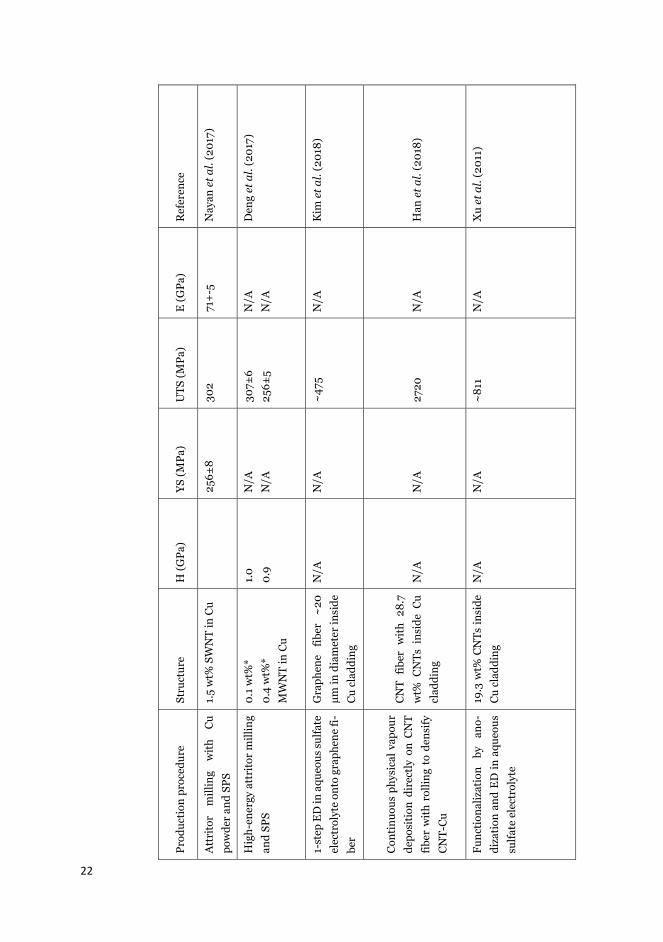
A literature overview of CNT-Cu composite properties produced by various production methods is compiled in Table 2. The hardness (H), yield strength (YS), ultimate tensile strength (UTS) and Young’s modulus (E) are reported. The literature survey clearly indi-cates that in most cases mechanical properties of copper can be successfully improved with an addition of CNTs inside a copper matrix. The ultimate tensile strength and Young’s mod-ulus are routinely improved over the highest values reported for Cu alloys. The hardness and yield strength of CNT-Cu are typically improved over pure Cu produced in similar con-ditions, while some Cu alloys in literature show higher values for these properties.

21
Tab
le 2
. Sel
ecte
d ro
om te
mpe
ratu
re m
echa
nica
l pro
pert
ies o
f Cu,
CN
T m
acro
stru
ctur
es a
nd th
eir c
ompo
site
s.
Prod
ucti
on p
roce
dure
St
ruct
ure
H (G
Pa)
YS (M
Pa)
UTS
(MPa
) E
(GPa
) R
efer
ence
Cu
wit
h up
to 4
0%
Zn
or 3
0%
Sn,
Al o
r N
i 0.
4-1.
8 30
-500
10
0-40
0 11
2-14
8 C
ES
Edu
pack
(20
18)
Fibe
r sp
un fr
om C
VD
mad
e M
WN
T ar
ray
As-
spu
n A
fter
twis
ting
N
/A
N/A
85
0
1910
27
5 33
0 Zh
ang
et a
l. (2
007)
Dry
spi
nnin
g fr
om C
VD
re-
acto
r SW
NT
and
DW
NT
fi-be
r N
/A
N/A
88
00
357
Koz
iol e
t al.
(200
7)
Hig
h en
ergy
ba
ll m
illin
g w
ith
Cu
pow
der
and
SPS
2.2
wt%
MW
NT
in C
u N
/A
197
281
137
Kim
et a
l. (2
006)
Func
tion
aliz
atio
n,
acti
va-
tion
, el
ectr
oles
s de
posi
tion
of
Cu
, mix
ing
by u
ltra
soni
-ca
tion
wit
h C
u po
wde
r an
d SP
S
0.1
wt%
* 1.
1 w
t%*
MW
NT
in C
u
1.3
1.0
142
120
~
180
~
140
N/A
Wan
g et
al.
(201
7)
22
Prod
ucti
on p
roce
dure
St
ruct
ure
H (G
Pa)
YS (M
Pa)
UTS
(MPa
) E
(GPa
) R
efer
ence
Att
rito
r m
illin
g w
ith
Cu
pow
der
and
SPS
1.5
wt%
SW
NT
in C
u
256±
8 30
2 71
+-5
N
ayan
et a
l. (2
017)
Hig
h-en
ergy
att
rito
r m
illin
g an
d SP
S 0.
1 w
t%*
0.4
wt%
* M
WN
T in
Cu
1.0
0.9
N/A
N
/A
307±
6 25
6±5
N/A
N
/A
Den
g et
al.
(201
7)
1-st
ep E
D in
aqu
eous
sul
fate
el
ectr
olyt
e on
to g
raph
ene
fi-be
r
Gra
phen
e fib
er
~20
μm
in d
iam
eter
insi
de
Cu
clad
ding
N/A
N
/A
~47
5 N
/A
Kim
et a
l. (2
018)
Con
tinu
ous
phys
ical
vap
our
depo
siti
on d
irec
tly
on C
NT
fiber
wit
h ro
lling
to
dens
ify
CN
T-C
u
CN
T fib
er w
ith
28.7
w
t% C
NTs
ins
ide
Cu
clad
ding
N
/A
N/A
27
20
N/A
H
an e
t al.
(201
8)
Func
tion
aliz
atio
n by
an
o-di
zati
on a
nd E
D in
aqu
eous
su
lfate
ele
ctro
lyte
19.3
wt%
CN
Ts in
side
C
u cl
addi
ng
N/A
N
/A
~81
1 N
/A
Xu
et a
l. (2
011)

23
Prod
ucti
on p
roce
dure
St
ruct
ure
H (G
Pa)
YS (M
Pa)
UTS
(MPa
) E
(GPa
) R
efer
ence
2-st
ep E
D o
n C
NT
fiber
to
prod
uce
Ni
inte
rfac
ial
laye
r
and
Cu
laye
r fr
om a
queo
us
elec
trol
ytes
an
d an
neal
ing
(300
ºC
)
0.5
wt%
Ni i
nter
faci
al
laye
r 15
.8 w
t% C
u as
cla
d-di
ng o
n fi
ber
N/A
N
/A
~83
0
N/A
Zo
u et
al.
(201
8)
Hig
h-en
ergy
ba
ll m
illin
g an
d ro
lling
to s
heet
s 0.
2 w
t%*
0.7
wt%
* 1.
2 1.
3
376
417
421
500
N/A
N
/A
Yoo
et a
l. (2
013)
Puri
fyin
g, e
lect
role
ss d
epo-
siti
on o
f Ni a
nd C
u, m
ixin
g w
ith
Cu
pow
der,
col
d co
m-
pact
ing,
sin
teri
ng, f
orgi
ng
an d
ie-s
tret
chin
g
1.1
wt%
2.
2 w
t%
SWN
T in
Cu
1.4
1.1
N/A
N
/A
370
340
N/A
N
/A
Hua
ng e
t al.
(201
7)
* If
not
giv
en in
the
ref
eren
ce, w
t% w
as c
alcu
late
d fr
om r
epor
ted
CN
T de
nsit
y. I
f th
e de
nsit
y is
not
giv
en t
he c
alcu
lati
on h
as b
een
done
by
usin
g SW
NT
dens
ity
of 1
.3 g
cm
-3 (S
aifu
ddin
et a
l., 2
012)
and
MW
NT
dens
ity
of 2
.1 g
cm
-3 (L
ehm
an e
t al.,
201
1).

24
2.4.3 Electrical and thermal properties of CNT-Cu composites
A considerable amount of literature has been published in the past 15 years for production of CNT-Cu composites and graphene based Cu composites by electrochemical and powder metallurgy methods. While improvements in absolute electrical and thermal conductivity for CNT-Cu composites have remained elusive, some encouraging improvements have been achieved in various other properties. Based on the literature, the most promising enhance-ments in CNT-Cu composite properties have been made in the past 5 years. The specific conductivity, i.e., electrical conductivity normalized by weight of the conductor, of some CNT based materials has been reported to be higher than pure Cu (Yang et al., 2008; Subra-maniam et al., 2013) and Al (Zhao et al., 2011). For applications in automotive and aero-space industries, every kilogram less weight is an important factor for economical and en-vironmental reasons due to reduced energy costs and reduced CO2 emissions of transpor-tation. A similar case could be made for the use of aluminium based conductors, which have a low price and high specific electrical conductivity due to low density of Al. However, alu-minium based conductors have higher thermal expansion, lower ampacity and higher cor-rosion susceptibility than pure Cu, which has limited their application outside of power transmission (Lienig, 2006). Other often proposed electrical and thermal applications for CNT based composite materials include interconnects in integrated circuits, thermal man-agement of electronic devices in heat sinks and applications in corrosive environments (Chai et al., 2008a; Subramaniam et al., 2013, 2014; ITRS, 2015; Sun et al., 2016; Lee et al., 2018). The most relevant results from literature are summarized in Table 3. Only a few re-sults by powder metallurgy methods are shown as the electrical and thermal properties re-ported in literature typically show no enhancements in electrical or thermal properties.
The electrical conductivity is represented by specific values ( s) and also ampacity (Jmax), thermal conductivity (κ), coefficient of thermal expansion (CTE) and temperature coeffi-cient of resistance (TCR) are shown. In most cases, the specific conductivity values given in Table 1 have been calculated by the author of this thesis, based on the reported conductivity and density in the papers. If no composite density has been given, the density of pure copper has been used (8.96 g cm-3) and thus the reported value is the minimum possible s. All of the ampacity studies use a different set-up with varying sample environment, e.g., ambient air, inert gas or vacuum, sample size, current application rate and so on. As such, a direct comparison between obtained ampacity values is difficult. The values for ampacity are therefore also mentioned as a function of the copper reference value given by the respective authors in their measurement set-up.
Specific conductivity ( ) is used to describe the electrical conductivity of materials with respect to their volumetric density. The specific conductivity of fibrous CNT based samples with varying diameters can be calculated using the equation:
(3)
, where is specific conductivity (S m-1 g-1 cm3), G is conductance (S), L is length (m) and LD is linear density (g/km). For standard metallic conductors this value can be calculated by dividing the electrical conductivity by volumetric density. (Lekawa-Raus et al., 2014) In

25
Publications I and II the specific electrical conductivity of CNT-Cu composites with various CNT wt% is investigated.
Ampacity (Jmax), also referred to as current-carrying-capacity, is the maximum current density that a conductor material can transmit without a change in its structure or decrease in other properties, mainly conductivity. Electromigration is the primary mechanism for failure of conductors operated at high current densities, where the mass-transport of atoms and Joule heating of the conductor lead to its failure. Traditional loosely bonded metals such as copper (Jmax ≈ 1-20 MA cm-2) fail mainly due to the current-induced diffusion of atoms. On the other hand, in pristine CNT materials ampacity is mostly due to the Joule heating occurring at the high electrical resistance of nanotube to nanotube junctions. (Subramaniam et al., 2013; Sundaram et al., 2017)
The importance of CTE is highlighted in applications where efficient heat dissipation through two different materials is required. In electronic devices, the heat sink material is often Cu or Al-based and heat source material Si-based. For application in small electrical devices the CTE of the heat sink material should be as close to that of Si as a large mismatch can cause non-uniform strain distribution, delamination and buckling at the interface, which can result in inefficient heat dissipation. The CTE of Si is 2.6 ppm K-1, while the value for Cu is ca. 6 times higher. (Subramaniam et al., 2014) Therefore, for an optimal interface, the CTE of the conductor material should be lowered as close to Si as possible (Sun et al., 2016). As previously mentioned, CTE for nanotubes is close to 0 ppm K-1 (Jiang et al., 2004).
Thermal conductivity (κ) is a measure the property of a material to conduct heat. Materials with a high κ are often used in heat sink applications in electronics, whereas materials with a low κ are used as thermal insulators. Thus, along with CTE it is an important parameter for applications in semiconductor-based electronics.
Temperature coefficient of resistance (TCR) shows how much the resistance of a conduc-tor increases with an increase in temperature. In metals used for conductor applications this value is positive, e.g., 3.9 ·10-3 K-1 for Cu, but for CNT this value can be negative, i.e., increased conductivity at higher temperatures, or positive, depending on the structure of the CNTs. Typical values are in the range of -0.4 to 0.4 ·10-3 K-1 (Vollebregt et al., 2013).

26
Ta
ble
3. S
elec
t ele
ctric
al a
nd th
erm
al p
rope
rtie
s of C
u an
d CN
T-Cu
com
posi
tes
Prod
ucti
on p
roce
dure
St
ruct
ure
(MSm
-1g-1
cm3 )
J max
(M
A c
m-2
),
chan
ge
com
-
pare
d to
Cu
ref-
eren
ce
κ (W
m-1
K-1
) C
TE (p
pm ˚
C-1
) TC
R (·
10-3
K-1
) R
efer
ence
Pu
re C
u 6.
52
1-20
16
0-40
0
16.9
-18
3.9
Lloy
d an
d C
lem
ent,
1995
; CE
S E
duPa
ck,
2018
Twis
t spi
nnin
g of
MW
NT
fore
st
MW
NT
wir
e 0.
87
0.02
, ~0.
4×
N/A
N
/A
-0.9
Su
ndar
am e
t al.
2017
a, 2
017b
Floa
ting
cat
alys
t CV
D to
prod
uce
CN
T fib
ers
and
film
s th
at a
re d
ensi
fied
by a
ceto
ne
CN
T fib
er
CN
T fil
m
~0.
4 (f
ilm)
N/A
77
0±10
(fi-
ber)
N/A
N
/A
Gsp
ann
et a
l., 2
017
Dry
impa
ct b
lend
ing
wit
h C
u po
wde
r an
d SP
S
1.0
wt%
MW
NT
in C
u
mat
rix
N/A
N
/A
325
N/A
N
/A
Chu
et a
l., 2
010
Func
tion
aliz
atio
n, m
ix-
ing
by u
ltras
onic
atio
n
wit
h C
u po
wde
r an
d SP
S
0.2
wt%
*
2.5
wt%
*
MW
NT
in C
u m
atri
x
N/A
N
/A
359
335
N/A
N
/A
Cho
et a
l., 2
010

27
Prod
ucti
on p
roce
dure
St
ruct
ure
(MSm
-1g-1
cm3 )
J max
(MA
cm
-2),
chan
ge c
om-
pare
d to
Cu
ref-
eren
ce
κ (W
m-1
K-1
) C
TE (p
pm ˚
C-1
) TC
R (·
10-3
K-1
) R
efer
ence
Func
tion
aliz
atio
n of
CN
Ts, m
ixin
g by
ultr
a-
soni
cati
on w
ith
CuC
r,
dryi
ng, S
PS a
nd s
inte
ring
1.2
wt%
* M
WN
T w
ith
Cr 7
C3 i
nter
face
in C
u
mat
rix
~6.
4
N/A
N
/A
N/A
1.
5 C
ho e
t al.,
201
7
1-st
ep E
D o
f Cu
on C
NT
film
in a
queo
us s
ulfa
te
elec
trol
yte
and
anne
alin
g
(900
ºC
)
Lam
inat
ed
Cu/
CN
T/C
u fil
m*
~2.
3 N
/A
N/A
N
/A
N/A
Ta
o et
al.,
201
7
2-st
ep E
D o
f Cu
on
MW
NT
wir
e in
org
anic
and
aque
ous
elec
trol
ytes
and
redu
ctiv
e an
neal
ing
(250
ºC
)
5.2
wt%
* M
WN
T- C
u
wir
e
~1.
3
0.06
, 1.2
8×
N/A
N
/A
1.7
Sund
aram
et a
l.,
2017
a, 2
018
2-st
ep E
D o
f Cu
on
alig
ned
SNW
T fil
m in
or-
gani
c an
d aq
ueou
s el
ec-
trol
ytes
and
red
ucti
ve
anne
alin
g (2
50 º
C)
10.6
wt%
* SW
NTs
-
Cu
film
~8.
2
600,
~ 1
00×
395
5 0.
75
Subr
aman
iam
et a
l.,
2013
, 201
4

28
Prod
ucti
on p
roce
dure
St
ruct
ure
(MSm
-1g-1
cm3 )
J max
(MA
cm
-2),
chan
ge c
om-
pare
d to
Cu
ref-
eren
ce
κ (W
m-1
K-1
) C
TE (p
pm ˚
C-1
) TC
R (·
10-3
K-1
) R
efer
ence
Rep
eate
d E
D o
f Cu
on
alig
ned
MW
NT
film
s in
aque
ous
sulfa
te e
lect
ro-
lyte
Lam
inar
com
posi
te
film
wit
h te
ns o
f
MW
NT
laye
rs (0
.20
wt%
) in
Cu
mat
rix
5.3
0.01
2, 1
.36×
28
3 N
/A
N/A
Sh
uai e
t al.,
201
6
2-st
ep E
D o
n C
NT
fiber
to p
rodu
ce N
i int
erfa
cial
laye
r a
nd C
u la
yer
from
aque
ous
elec
trol
ytes
wit
h
anne
alin
g as
fina
l ste
p
(300
ºC
)
15.8
wt%
* C
NTs
wit
h
0.5
wt%
Ni i
nter
faci
al
laye
r
insi
de C
u cl
addi
ng
~5.
5 0.
106,
1.0
9×
N/A
N
/A
1.14
Zo
u et
al.,
201
8
Func
tion
aliz
atio
n of
CN
T
fiber
by
anod
izat
ion
and
1-st
ep E
D in
aqu
eous
sul
-
fate
ele
ctro
lyte
CN
T fib
er w
ith
24
wt%
CN
Ts in
side
(3
μm th
ick)
Cu
clad
ding
6.0
N
/A
N/A
N
/A
N/A
X
u et
al.,
201
1
Con
tinu
ous
phys
ical
va-
pour
dep
osit
ion
dire
ctly
on C
NT
fiber
wit
h ro
lling
to d
ensi
fy C
NT-
Cu
CN
T fib
er w
ith
28.7
wt%
CN
Ts in
side
Cu
clad
ding
5.6
N/A
N
/A
N/A
N
/A
Han
et a
l., 2
018

29
Prod
ucti
on p
roce
dure
St
ruct
ure
(MSm
-1g-1
cm3 )
J max
(MA
cm
-2),
chan
ge c
om-
pare
d to
Cu
ref-
eren
ce
κ (W
m-1
K-1
) C
TE (p
pm ˚
C-1
) TC
R (·
10-3
K-1
) R
efer
ence
1-st
ep E
D in
aqu
eous
sul
-
fate
ele
ctro
lyte
ont
o gr
a-
phen
e fib
er
Gra
phen
e fib
er ~
20
μm in
dia
met
er in
side
Cu
clad
ding
~4.
1 ~
1, 1
0×
354±
100
N
/A
N/A
K
im e
t al.,
201
8
ED
of C
u on
to p
atte
rned
CN
T ve
rtic
al a
rray
wit
h
sput
tere
d 10
nm T
i and
20 n
m A
u
5.5
wt%
* C
NT
arra
ys
200 μm
in d
iam
eter
depo
site
d w
ith
Cu
clad
ding
~1.
6 N
/A
N/A
5.
0 2.
1 Su
n et
al.,
201
6
Aqu
eous
co-
depo
siti
on o
f
func
tion
aliz
ed S
WN
Ts
and
Cu
1.6
wt%
* SW
NTs
em
-
bedd
ed in
Cu
mat
rix
~7.
4 N
/A
N/A
N
/A
N/A
Ya
ng e
t al.,
200
8
1-st
ep a
queo
us E
D o
nto
CN
T fib
er
MW
NTs
par
tly
depo
s-
ited
insi
de th
e fib
er
wit
h a
Cu
clad
ding
of
few
μm
~2.
7 ~
10, 5
0×
N/A
N
/A
N/A
R
ho e
t al.,
201
8
Func
tion
aliz
ing
CN
Ts,
sint
erin
g w
ith
PEI
mod
i-
fied
Cu
pow
der
3D n
itro
gen
dope
d
CN
T-C
u w
ith
1 w
t%
MW
NTs
~6.
1 0.
07, 3
×
548
N/A
N
/A
Ye e
t al.,
201
8
* If
not
giv
en in
the
refe
renc
e, w
t% w
as c
alcu
late
d fr
om r
epor
ted
CN
T de
nsit
y. I
f the
den
sity
is n
ot g
iven
the
calc
ulat
ion
has
been
don
e us
ing
SWN
T de
nsit
y of
1.3
g c
m-3
(Sai
fudd
in e
t al.,
201
2) a
nd M
WN
T de
nsit
y of
2.1
g c
m-3
(Leh
man
et a
l., 2
011)
.

30
Based on the reported results in Table 3, following general observations can be made: Some of the reported composite structures have CNTs embedded inside a continuous copper ma-trix, while others consist of an inner CNT layer coated with a copper cladding. CNT-Cu com-posites have been produced with the alignment of nanotubes inside the Cu matrix both per-pendicular and parallel to the axial direction. The density of produced CNT-Cu composite is obviously highly dependent on the amount of CNTs incorporated. The lowest reported densities are in the range of ~2-3 g cm-3, when CNT material is coated with a thin layer of Cu (~ few μm of Cu), such as by Xu et al. (2011) and Randeniya et al. (2010). CNT macro-structures have also been deposited with Cu to form a continuous CNT-Cu matrix with a minimum density of ~5 g cm-3 (Subramaniam et al., 2013; Sundaram et al., 2017a). This low density coupled with a slightly lower electrical conductivity than pure Cu (typically in the range of 10 to 95 %IACS) can result in CNT-Cu material exhibiting high specific conductivity as shown by Subramaniam et al. (2013) and Yang et al. (2008). The common theme among the studies showing improved specific conductivity is that the nanotubes inside the CNT matrix do not show considerable nanotube bundling, but exist as individual nanotubes sep-arated by the Cu matrix. Therefore in these composites the amount of high resistance CNT-CNT electrical junctions is minimal.
A majority of the composites that have low density (and conversely, a high wt% of CNTs) were produced by electrochemical methods. This is due to the aforementioned agglomera-tion issue in high temperature methods in Section 2.3, which severely limits their produc-tion capability of high wt% CNT Cu composites. Similar to electrical conductivity, the ther-mal conductivity of reported CNT-Cu materials are typically at best close to values of pure Cu (Cho et al., 2010; Chu et al., 2010; Subramaniam et al., 2014; Shuai et al., 2016; Kim et al., 2018). However, recently Ye et al. (2018) reported their CNT-Cu to exhibit a thermal conductivity of 548 Wm-1K-1 (~37 % higher than bulk Cu), which is highly promising for the future development of thermal capabilities of CNT-Cu.
To the author’s knowledge, the first to report increased electromigration resistance, i.e., ampacity, were Chai et al. (2008b), for nanotubes vertically embedded inside a Cu matrix. Since then, several authors (Subramaniam et al., 2013, 2014; Shuai et al., 2016; Sundaram et al., 2017a, 2018; Kim et al., 2018; Rho et al., 2018; Zou et al., 2018) have reported in-creased ampacity of their CNT-Cu (or graphene-Cu) composites, compared against a copper reference sample in the same set-up. The improvement has been observed for various types of CNT-Cu configurations with both Cu cladding on CNT material and CNTs embedded in-side a Cu matrix, with the property measured both perpendicular and parallel to the nano-tube alignment. The high ampacity is typically attributed to supressed electromigration of Cu atoms due to an increase in the copper activation energy. However, recent simulations by Lee et al. (2018) suggest that the decrease in electromigration of CNT-Cu is not related to changes in activation energy, but can be attributed to reduced self-heating of the compo-site when compared with pure Cu. The TCR of CNT-Cu can also be decreased considerably when compared with pure Cu, for both CNTs inside a Cu matrix (Subramaniam et al., 2013; Cho et al., 2017; Sundaram et al., 2017a) and for CNT material coated with a Cu cladding (Sun et al., 2016; Zou et al., 2018). This enhancement shows potential for possible high temperature applications of CNT-Cu. For instance, due to its low TCR (0.75·10-3 K-1) the CNT-Cu composite reported by Subrama-

31
niam et al. (2013) has a higher electrical conductivity than pure copper at 80 ˚C. Further-more, a low CTE has been reported by many authors for both CNT-Cu composites with CNTs embedded in Cu matrix (Kim et al., 2011; Subramaniam et al., 2014) and CNTs with a Cu cladding (Sun et al., 2016) as the CNTs restrain the thermal expansion of Cu.
To summarize, improvements in various electrical properties other than specific conduc-tivity appear more easy to obtain as they can be found for various CNT-Cu configurations and the type and quality of employed CNT starting material does not appear as critical. In-creased ampacity, a low coefficient of thermal expansion and a low temperature coefficient of resistance are often found in carbon nanotube-Cu composites by electrodeposition.
The outlined improvements in electrical and thermal properties of CNT-Cu composites appear beneficial for applications in interconnects, heat sinks and overhead lines that are subject to high temperatures and current densities (Lin et al., 2018). As interconnects are currently made by Cu electrodeposition (Damascene process) and the highest electrical and thermal properties have been achieved by electrodeposition of Cu on CNT macrostructures, this method appears prominent also for the production of CNT-Cu for interconnect appli-cations. In such a case, the CNT structure would require to be templated in the interconnect feature before being electrodeposited with Cu similarly as the results achieved by Subrama-niam et al. (2016). Another method would be to co-deposit CNTs with Cu inside the narrow feature, but to the author’s knowledge this has not yet been attempted. It should be noted that the range of obtained results is still large and the most impressive results by Subrama-niam et al. (2013, 2014, 2016) are yet to be replicated by other researchers.
2.4.4 Corrosion properties of carbon-Cu composites
To date, the corrosion behaviour of carbon nanotube based copper composites has not been thoroughly studied. In this section the relevant studies from literature are briefly discussed along with the theoretical background for corrosion of CNT-Cu composites. Due to the lack of literature on CNT based composites, some graphene and graphene oxide (GO), which are analogous to CNTs, based Cu- composites have also been included in the discussion.
Firstly, due to the high standard electrode potential of carbon, CNTs in a composite should act as the cathode and the copper matrix as the anode when in contact with a corroding solution (for example a solution containing 3.5 wt% NaCl, which simulates a highly corro-sive medium; sea water). Therefore, it could be expected that the addition of CNTs in copper matrix could induce galvanic corrosion of the copper due to galvanic pairing of CNTs and Cu. Secondly, because of the inert chemical nature of graphitic carbon, CNTs might help create a passive film on the surface of metals and increase the nobility of the composite material (Praveen et al., 2007; Bakshi et al., 2010; Singh et al., 2013). Thirdly, CNTs might indirectly affect the corrosion of copper based composites by affecting the surrounding structure of the copper matrix during production. For example, co-deposition of copper with nanotubes from solution by electrodeposition has been shown to decrease the grain size of the copper matrix (Yang et al., 2008), which could increase the corrosion rate of the copper matrix due to the existence of more grain boundaries that are susceptible to corro-sion attack.
A majority of the literature shows an improvement in corrosion properties when carbon nanotubes or graphene are coated on copper. These results are typically attributed to the highly inert nature of the carbon, which shields the copper underneath. This situation is identical to protection of metals using a high-quality paint coating. However, to the author’s

32
knowledge, only a single study besides Publication IV has investigated the corrosion perfor-mance of embedded carbon nanotubes inside a copper matrix. Ghanbari & Darabi (2015) reported that the corrosion resistance of their CNT-Cu micropillars was increased by six fold when compared with pure Cu micropillars.
It is interesting to note that the reported galvanic corrosion behaviour of carbon based composites differs depending on the source. Some authors report strong galvanic corrosion between carbon based constituents and metal matrix. For instance, Orth & Wheat (1997) showed in their work that increasing graphite content in the range of 1.2 to 40 vol% in cop-per matrix composite consolidated by powder metallurgy increases the severity of corrosion attack in 3.5 wt% NaCl. A higher graphite content increased the localized galvanic corrosion at the interface between copper and graphite. Opposite results were obtained by Zhao et al. (2007), who produced copper-graphite composite coatings by electroforming, where no gal-vanic corrosion was observed between the two constituents in 3.5 wt% NaCl. In their work, corrosion was shown to occur at grain boundaries while the graphite particles hindered the corrosion process by modifying the microstructure of Cu.
Table 4 shows a summary of some reports found in literature on the corrosion properties of different types of Cu composites based on CNTs, graphene or graphene oxide. The best corrosion performance of composite samples is compared to the reported Cu reference.

33
Tabl
e 4.
Cor
rosi
on p
rope
rtie
s of s
elec
t car
bon
base
d m
etal
com
posi
tes.
Stru
ctur
e Pr
oduc
tion
pro
-ce
dure
Cor
rosi
ve m
e-di
um
Car
bon
type
and
dim
en-
sion
s (L
x D
) C
orro
sion
rat
e co
m-
pare
d w
ith
Cu
Eco
rr, c
ompo
site
vs.
C
u (V
) So
urce
Gra
phen
e ox
ide
coat
ing
on C
u E
lect
roph
oret
ic
depo
siti
on
3.5
wt%
NaC
l G
raph
ene
oxid
e fla
kes;
40
nm
thic
k co
atin
g 10
.5%
by
Tafe
l ana
ly-
sis
-0.6
9 V
vs.
-0
.21
V
wit
h A
g/A
gCl r
ef.
Sing
h et
al.,
201
3
Gra
phen
e co
ated
Cu
Dir
ect
grow
th o
f gr
aphe
ne o
n C
u by
su
rfac
e-ca
ta-
lyze
d pr
oces
s
0.6
wt%
NaC
l M
ostl
y si
ngle
or
two
lay-
ers
of g
raph
ene
coat
ing
25%
by
Tafe
l an
aly-
sis
-0.1
3 V
vs.
0.0
4 V
vs
. SC
E
Kir
klan
d et
al.,
201
2
Cu/
grap
hite
coa
ting
on
sta
inle
ss s
teel
E
lect
rofo
rmin
g 3.
5 w
t% N
aCl
Gra
phit
e pa
rtic
les
5 μm
in
dia
met
er
Com
posi
te i
ndic
ates
in
crea
sed
corr
osio
n re
sist
ance
vis
ual
in-
spec
tion
.
N/A
Zh
ao e
t al.,
200
7
Cu-
gr
aphi
te
com
-po
site
Hig
h-en
ergy
hi
gh- r
ate
cons
ol-
idat
ion
1.2
vol%
40
vol
%
3.5
wt%
NaC
l G
raph
ite
flake
s 44
μm
in
diam
eter
A
ll co
mpo
site
s in
di-
cate
incr
ease
d co
rro-
sion
due
to b
oth
uni-
form
cor
rosi
on a
nd
galv
anic
cor
rosi
on.
-238
V v
s.
-0.1
99 V
vs.
SC
E
Ort
h &
Whe
at, 1
997

34
Stru
ctur
e Pr
oduc
tion
pr
o-ce
dure
Cor
rosi
ve m
e-di
um
Car
bon
type
and
dim
en-
sion
s (L
x D
) C
orro
sion
rat
e co
m-
pare
d w
ith
Cu
Eco
rr,
com
posi
te v
s.
Cu
(V)
Sour
ce
Gra
phen
e co
ated
C
u D
irec
t gro
wth
of
grap
hene
on
Cu
by C
VD
0.6
wt%
NaC
l O
ne to
two
laye
rs o
f gr
aphe
ne
1-10
% b
y Ta
fel a
nal-
ysis
-0
.15
V v
s. -0
.19
V
vs. S
CE
R
aman
et a
l., 2
012
CN
T-C
u m
icro
pil-
lars
C
o-de
posi
tion
of
CN
Ts w
ith
Cu
3.5
wt%
NaC
l M
WN
T, 1
-2 μ
m lo
ng a
nd
10 n
m d
iam
eter
17
% b
y E
IS c
orro
sion
re
sist
ance
m
easu
re-
men
t
N/A
G
hanb
ari &
Dar
abi,
2015
Gra
phen
e ox
ide-
Cu
com
posi
te
coat
ing
on s
teel
Co-
depo
siti
on o
f G
O w
ith
Cu
3.5
wt%
NaC
l G
raph
ene
oxid
e fla
kes
15%
by
Tafe
l af
ter
5 da
ys in
sol
utio
n -0
.46
V v
s. -
0.60
V
vs. A
g/A
gCl
Rag
thup
athy
et a
l., 2
017
Gra
phen
e- C
u co
m-
posi
te
coat
ing
on
stee
l
Co-
depo
siti
on o
f gr
aphe
ne w
ith
Cu
3.5
wt%
NaC
l G
raph
ene
flake
s 56
% b
y Ta
fel
anal
y-si
s -0
.58
V v
s. -
0.43
V
vs. A
g/A
gCl
Kam
boj e
t al.,
201
7

35
3. Experimental
This chapter provides a summary of the materials, experimental set-ups and procedures employed in Publications I-IV. More detailed explanations of each of the experiments are given in the respective publications. The experimental portion of this work mainly focuses on the electrochemical characterization, preparation and deposition of copper on CNT macrostructures and their resulting specific electrical conductivity. CNT macrostructures produced at the University of Cambridge consisting of fiber, yarn and film, were the focus of copper deposition studies (Publications I-III). A CNT-Cu wire produced in collaboration with Nexans Research Centre in Lens and University of Cambridge, by casting and drawing, was the focus of corrosion studies by mostly electrochemical methods (Publication IV).
3.1 CNT raw material preparation
The CNT raw material used in publications I-IV was produced at the University of Cam-bridge. The CNT material was produced by the floating catalyst CVD dry spinning method with a ferrocene catalyst as shown in Figure 9 and demonstrated by Koziol et al. (2007), Lekawa-Raus et al. (2014) and Janas & Koziol (2016). The winder was covered with trans-parent acetate sheets, aluminium foil, or sheets of writing paper, which could be removed from the winder to retrieve the sample material. CNT films were produced by winding a large amount of CNT fibers on the roll until individual CNT fibers are were longer visible and the structure was a planar sheet of aligned nanotubes. CNT fibers were produced in the same way but with shorter production times. The CNT film was used to produce CNT yarns by the author by hand into a wire form. Suitable sized film samples (0.1 to 1 cm in width) were cut with a surgical blade and then rolled by hand and densified by spraying with ace-tone, to induce bundling as shown by Tawfick et al. (2013). The obtained yarn structure was similar to single CNT fibers in its inhomogeneous fiber-like nature, but with larger diame-ter, higher density and thus smaller resistance and higher weight. Based on their dimen-sions and weight pristine CNT fibers were estimated to have an average density of ~0.7 g cm-3 and the CNT yarns a density of ~1 g cm-3 (Lekawa-Raus et al., 2014). The difficulty in obtaining exact values for various properties of these materials is due to the inhomogeneous nature of the CNT macrostructures; the diameter and density are not constant along the length of the studied specimens. CNT fibers and yarns consisting of SWNT, DWNT and MWNT (Publication I and II), CNT films consisting of SWNT, DWNT and MWNT (Publication III and IV) and CNT powder consisting of MWNT (Publication IV) were employed as the nanocarbon source in the pro-duction of CNT-Cu composite materials. CNT fibers of different diameters (D =~5, 10 and

36
30 μm) synthesized in different batches with different winding rate were utilized in electro-deposition studies (Publications I and II). Table 5 shows some of the material properties of the employed CNT macrostructures.
Figure 9. CVD dry spinning method to produce CNT fiber and CNT film at University of Cambridge. Modified from Lekawa-Raus et al. (2014).
Table 5. Properties of the employed CNT material obtained from University of Cambridge.
Thickness (μm)
Density (g cm-3)
Specific surface area (m2 g-1)
CNT distribu-tion
CNT fiber 5, 10, 30 0.7 450 > 80 % MWNT
CNT film 15 0.9 200 > 80 % MWNT
3.2 CNT material characterization
Scanning electron microscopy (SEM) attached with energy-dispersive X-ray spectroscopy (EDS) was used in observing the pristine and copper deposited CNT structures and compo-sitions in Publications I-IV. More details of the utilized SEM-EDS parameters are given in the publications. ImageJ software version 1.51 (National Institutes of Health, Bethesda, MD, USA) was used in analysis of Cu grain sizes and population densities on CNT films and fibers in Publications I and II. Raman spectroscopy (LabRAM HR UV-NIR) with red excitation wavelength of 633 nm was used to characterize the relative levels of functionalization of pristine and functionalized CNT films in Publication III. The spectra were baseline cor-rected and the curves were fitted with the Gaussian-Lorentzian function. The reported

37
ID/IG-ratios for each sample are an average of five measurements at different surface loca-tions on the CNT film sample.
The electrical resistance of CNT macrostructures and also produced CNT-Cu material was measured with a custom made four point measurement circuit of copper connections, shown in Figure 10. The CNT raw material was carefully contacted to the four electrodes with tiny droplets of conductive silver paint (42469, Alfa Aesar, USA). Once the CNT mate-rial was fixed on the electrodes, the paint was allowed to dry (typically 24 hours in ambient conditions) to minimize contact resistance between the copper electrodes and CNT mate-rial. The electrical resistance could then be measured with a multimeter (Fluke 8846a) at-tached to the circuit. Resistance of various lengths (3 to 15 cm) of CNT fibers and yarns could be measured with this setup. The circuit was also used to measure the resistance of CNT-Cu composite fibers and yarns produced in Publications I & II. In this case the wires could be mechanically fixed on the circuit by clamping as the electrical contact between cop-per electrodes and the copper coated CNT material was sufficient.
Figure 10. Printed circuit board used in the four wire electrical resistance measurement of CNT and CNT-Cu material.
3.3 Electrochemical cell set up and methods
All the electrochemical cell set ups utilized in Publications I-IV were three electrode cells controlled with a potentiostat at room temperature. The employed reference electrode was either a copper/copper sulphate (Cu/CuSO4) or a standard calomel electrode (SCE) (Publi-cation II-IV). In electrodeposition studies the counter electrode was a U-shaped copper sheet (99.99 % purity) fixed on both sides of the working electrode (Publication I, II and III). For purposes other than electrodeposition, a platinum counter electrode was utilized (Publication II, III and IV), except in the zero resistance amperometry (ZRA) experiment in Publication IV, where a CNT film was utilized as the counter electrode. In the electrochem-ical deposition, electro-oxidation and corrosion behaviour studies the counter electrode area was larger than the immersed CNT material area to ensure an even current distribu-tion. For the ZRA experiment the CNT film utilized as counter electrode had the same geo-metrical surface area as the copper plate.
To study the electrochemical properties of CNT macrostructures, electro-oxidize the ma-terial and to deposit the material with copper, a custom sample holder made of PVC plastic

38
was designed. With the sample holder, the lightweight and fragile fiber, yarn and film sam-ples could be rigidly fixed in employed solutions and electric current could be passed relia-bly and evenly through a single electrical contact made with conductive silver paint (42469, Alfa Aesar, USA). The CNT samples in this case could be up to 11 cm in length. The plating setup used in Publications I-III is shown in Figure 11. Longer and more heavy CNT yarn samples (up to ca. 30 cm) could be deposited without a sample holder, simply by gluing a small piece of PVC plastic at the bottom of the yarn to hold the sample straight in an other-wise similar setup.
Figure 11. Plating setup and sample holder: 1. CNT fiber, 2. Silver paste electrical contact, 3. Glue, 4. Copper sheet anode, 5. Copper wire, and 6. PVC sample holder (Publication I)
The electrolytes used in electrochemical deposition were aqueous based copper sulfate baths in similar concentrations as often applied in electrodeposition of copper on carbon materials and in industrial electroplating (Paunovic & Schlesinger, 2006; Sundaram et al., 2017a; Tao et al., 2017; Chen et al., 2018a; Kim et al., 2018). The following electrochemical deposition electrolytes were used:
Electrolyte I: 0.8 M CuSO4·5H2O and 0.4 M H2SO4 (Publication I) Electrolyte II: 0.6 M CuSO4·5H2O, 0.8 M H2SO4 and 0.1mM NaCl (Publication II) Electrolyte III: 0.6 M CuSO4·5H2O and 0.9 M H2SO4 (Publication III) Electrolyte IV: 0.1 M CuSO4·5H2O, 3 M H2SO4, 1.0 mM NaCl and industrial accel-
erator CG 2001 Additive (Shipley) 0.8 ml/l
Galvanostatic deposition (Publication I, II and III) and potentiostatic oxidation (Publication III) techniques were utilized in production of CNT-Cu composites. In galvanostatic deposi-tion, i.e., copper reduction, the applied current, typically in the range of -0.05 up to -30 mA, depending on the size of the utilized CNT macrostructure, is fixed to a determined value and the working electrode potential is recorded. Conversely, in potentiostatic oxidation the po-tential difference between the working and reference electrode is set to a determined value and the current passing between the counter electrode and working electrode is recorded. Cathodic polarization curve was also applied to observe material reactivity in copper sul-phate solution (Pulication III). In this technique, the working electrode potential is changed with a pre-determined speed and the resulting current passing through the working elec-trode is recorded as a function of overpotential. With this technique, the onset of cathodic

39
electrochemical reactions can be identified and the electrochemical reactivity of the working electrode material observed.
3.4 Oxidation of CNT material
Two different oxidation treatments were employed for CNT fibers and CNT film materials as a pre-treatment before electrodeposition in Publication III. These treatments were em-ployed in order to modify the electrochemical behaviour of the CNT macrostructures. Oxi-dation was carried out in a furnace of ca. 2 dm-3 volume (Scandia Oven K4/PDI) under a constant oxygen flow of 150 SCCM (standard cubic centimeters per minute) at the temper-atures 400, 450 or 500 ºC for 20 and 60 minutes. An electrochemical oxidation method was also applied, where the CNT material was immersed in 1 M H2SO4 and anodized, i.e., elec-tro-oxidized, at various potentials from 1 V to 2.5 V vs. SCE, for 1 to 10 minutes using a platinum sheet counter-electrode (Publication III). The degree of oxidation was determined by Raman spectroscopy and the appearance of functional groups was observed with FTIR. The effect of oxidation could also be seen in contact angle measurements, which were per-formed by placing a drop of electrolyte from a pipette on the surface of CNT film and ob-serving the possible contact angle. High contact angles are caused by hydrophobicity be-tween the material and droplet (in our case aqueous based electrolyte).
3.5 Specific electrical conductivity
The electrical resistance of pure CNT material and CNT-Cu composite fibers were recorded with a multimeter and a custom 4-point resistance circuit shown in Figure 10. The light-weight CNT fiber based samples were weighed with an Ultramicro scale (Sartorius) with 1μg resolution and the yarn samples were measured with AT261 DeltaRange scale (Mettler To-ledo) with 10 μg resolution. The length of the samples (3 to 15 cm) was also measured simply with a ruler. The specific conductivity of samples could then be calculated (Publication I, II) by using equation (3).
3.6 Corrosion behaviour
In this work, the corrosion properties of cast and deformed CNT-Cu wires were investigated in 3.5 wt% sodium chloride (NaCl), which is similar to sea water and thus commonly used in corrosion studies (Yang et al., 2001). Corrosion properties of CNT-Cu wires (Publication IV) were studied by various electrochemical techniques: observing free corrosion potential, measuring polarization resistance and polarization curves, and zero resistance amperome-try.
Polarization curve is a commonly applied electrochemical method for corrosion rate esti-mation. In this method, the sample is polarized from a given value below its corrosion po-tential to a given value above the corrosion potential. The Tafel method is then utilized to obtain the anodic and cathodic Tafel constants from the polarization curves from the linear range ca. 100-200 mV from the corrosion potential. At the intersection of these slopes the anodic and cathodic reaction rates are equal and the corrosion current can be estimated from this point.

40
Increase in the free corrosion potential can indicate either decrease in anodic reaction rate or increase in cathodic reaction rate. In the case of a passivating layer formation on copper, such as a copper chloride film, typically the rate of anodic reaction, i.e., the rate of corrosion decreases. The composition and formation of the passive film is dependent on the compo-sition of the corroding environment and can form rapidly or slowly with time.
Linear polarization resistance (LPR) measurement was used to record the I-E curve of the studied material. The sample was polarized only up to 10 mV from its open circuit potential. In this way, the polarization is non-intrusive and does not change the surface properties of the sample. Therefore, it can be applied multiple times successively for a sample immersed in a corrosive environment. As the corrosion rate is directly dependent on the kinetics of anodic and cathodic reactions, the small externally applied potential shift and its resulting measurable current flow can be utilized to estimate the corrosion rate. The smaller the measured current flow for a given potential shift, the smaller the icorr and the higher the polarization resistance.
The corrosion rate is obtained from the Stern-Geary equation (Stern & Geary, 1957):
(4)
, where is the polarization resistance, is the applied polarization, is the observed
current and and are the anodic and cathodic Tafel constants, respectively, as observed from the polarization measurements. Various methods were used to detect for possible galvanic corrosion of the CNT-Cu samples. The galvanic current between CNT based material and pure copper plate was studied with the zero resistance amperometry (ZRA) method. The method uses a three-electrode cell, where the working electrode and counter electrode materials are the industrial grade pure copper plate (99.99 % purity) and CNT film, respectively. The potential difference between the materials is set to zero and the resulting current passing through the cell is observed. In theory, the larger the potential difference between the materials, the larger the expected current and the stronger the expected galvanic corrosion.
An estimation of the galvanic corrosion can also be obtained with mixed potential theory analysis. In this method the pure materials which form the basis of the composite material, are polarized individually. The polarization curves are then plotted on the same graph. From this graph the cathodic reaction happening on the noble material, and the anodic reaction occurring on the less noble material are observed. During corrosion the anodic and cathodic reactions occur at the same rate, and the intersection of these curves yields the corrosion current density, i.e., the expected galvanic corrosion rate within the composite material.
Another method used to observe for the galvanic corrosion was the visual observation of the corroded material surface by SEM. If the corrosion attack is situated at the boundary between the constituent materials, in this case CNTs and the copper matrix, there should be visible corrosion, such as pits or grooves at the interface.

41
3.7 Casting and drawing to produce CNT-Cu wire
The cast and drawn CNT-Cu wires used in corrosion studies (Publication IV) were produced by Nexans in Lens, France. A novel method was employed to produce this composite wire. First, a thin layer of CNTs (ca. 10 μm) was coated onto an oxygen free copper wire, with the method reported previously by Janas et al. (2017). This CNT coated copper wire was then electrodeposited with copper from typical copper sulphate electrolyte to produce a sand-wich Cu-CNT-Cu wire that could be easily manipulated. This wire was introduced into mol-ten copper during casting by using a hollow casting pin. The sandwich structure is employed to minimize CNT agglomeration and to help with CNT dispersion in liquid copper. With the help of the casting pin the sandwich Cu-CNT-Cu wire can be introduced close to the copper solidification area thus ensuring a homogeneous distribution of CNTs in copper. Due to this procedure, the CNTs are not thermodynamically separated from the copper and are trapped at the grain boundaries during solidification. CNTs consisting of multiwalled tubes with outer diameter of 30–40 nm and length of 10 μm were provided by the University of Cam-bridge, UK. Wire rods 15 mm in diameter were cast at a speed of approximately 6 kg/h. After casting, the rod samples were transformed to final shape by rolling and cold drawing. A reference sample (CuOF) was produced from industrial grade oxygen free copper that was rolled and drawn to 1 mm from original 12 mm diameter rod.

42
4. Results and discussion
Several factors make macroscopic CNT electrodes different from the typically utilized elec-trically conductive planar electrode materials in electrodeposition. Firstly, the employed CNT materials are known to have high electrical resistivity and fibrous nature. Secondly, pristine CNT material is chemically inert with some impurities present and thus it is not clear how copper will deposit on its surface. Thirdly, as CNTs are known to be inherently hydrophobic, it is not obvious how this will affect the electrodeposition process from aque-ous based electrolytes. Therefore, the investigation of the electrochemical deposition pro-cess of copper on CNT macrostructures was one of the main tasks of this research. Further-more, the specific electrical conductivity of resulting CNT-Cu and its relationship with the composite microstructure after electrodeposition were examined and the corrosion behav-ior of CNT-Cu composites formed by casting and drawing was investigated. The following Sections further elaborate the findings.
The objectives of this work were presented in Section 1.2. The electrochemical deposition process on individual CNT fibers and its effect on specific electrical conductivity was char-acterized in Publication I. In Publication II the electrochemical deposition process and its effect on specific electrical conductivity was studied for CNT yarns of larger dimensions. In Publication III the electrochemical deposition process was researched on pristine and func-tionalized CNT films. The corrosion behaviour of CNT-Cu wires was examined in Publica-tion IV to further investigate their potential as a conductor material.
4.1 Characteristics of employed CNT material
Three different CNT macrostructures were employed in this work: CNT fiber, CNT film and CNT yarn as shown previously in Figure 3. Characteristics of these materials can be found in previously shown Table 5. The CNT fiber material has been previously characterized ex-tensively (Koziol et al., 2007; Janas & Koziol, 2016). The electrical conductivity of the CNT fiber material was measured in Publication I. An exact value of the electrical conductivity is difficult to obtain due to the fibrous nature of the carbon nanotube samples. Based on mul-tiple CNT fiber samples with different average diameters and lengths, the electrical conduc-tivity was found on average as ca. 300 S/cm (Publication I). However, considerable varia-tion (~ ±50%) was noted in the electrical resistance between fiber samples even of the same average diameter. This conductivity value is at the low end of the CNT fibers (10 to 67 000 S/cm) produced by different methods reported in literature (Lekawa-Raus et al., 2014). While a CNT fiber produced by the same method has been reported to have a specific con-ductivity of up to 0.7 MSm-1g-1cm3, the CNT fibers employed in this study had a calculated specific conductivity an order of magnitude lower at ca. 0.04 MSm-1g-1cm3. The weight of

43
individual CNT fibers up to 11 cm in length was below 10 μg. In contrast, the weight of sim-ilar lengths of CNT yarns was up to a few milligrams, depending on the amount of CNT film that was rolled into yarn. The orientation of CNTs was mostly in the axial direction in films and fibers, as shown in Figure 12. Table 6 shows the EDS analysis of a pristine CNT film used in Publication III, where some impurities such as iron from ferrocene catalyst particles can be detected. The other elements (S, Si, Na, Ca) at lower concentrations are likely a con-tamination from the production and handling process.
Table 6. SEM-EDS analysis of CNT film surface (Publication III).
C O Fe S Si Na Ca wt% 88.48 9.20 1.27 0.40 0.16 0.34 0.16
At the surface of all studied pristine CNT materials some soot, i.e., amorphous carbon, was typically present as various sized particles, see, e.g., Figure 12a. In literature amorphous carbon is also often reported as a ~nm scale partial coating on the surface of individual CNTs, which cannot be deduced from SEM images. The porous nature of the material is also visible in Figure 12b and c, where the distances between nanotubes and nanotube bundles are on the order of a few hundred nanometers. The density of CNT fibers utilized in this work were estimated to be 0.7 g cm-3 (Koziol et al., 2007) due to lack of densification or twisting, which are often applied by other researchers in the production of CNT fibers. The density of the employed CNT fiber samples is thus in the low range of the values (0.3-2 cm-
3) typically reported for CNT fibers (Lekawa Raus et al., 2014; Sundaram et al., 2018). The employed CNT fiber consists mostly of curved MWNTs and exhibits a considerable amount of impurities, e.g., soot. These factors are known to adversely affect the electrical conduc-tivity of CNT materials and explain at least partly the low electrical conductivity of the ma-terial in this thesis (Dai et al., 1996; Behabtu et al., 2013; Lekawa-Raus et al., 2014).
Figure 12. Observed surface morphology of (a),(b) CNT film and (c) CNT fiber.
A CNT fiber sample was cut by focused ion beam (FIB) to observe its interior as shown in Figure 13. Due to the low weight and density of the sample, an even surface was difficult to obtain. However, the microstructural characteristics, namely porosity, of the CNT fiber ma-terial could still be observed. The interior of the fiber showed relatively large voids up to ca. 5 μm in diameter, Figure 13a. The longitudinal cross section further demonstrates the fi-brous nature of the CNT fiber in its axial direction, Figure 13b.

44
Figure 13. (a) Transverse and (b) longitudinal CNT fiber (used in Publication I & II) cross sections by focused ion beam milling.
The diameter variation of some CNT fiber samples was pronounced as can be seen in Figure 14. It has to be noted that due to the fibrous nature of the material the variation shown in Figure 14 could appear more pronounced than during electrodeposition, as the samples are not stretched on the carbon tape when in SEM. Due to the variations in fiber and yarn ge-ometry, the cathodic current used in electrochemical deposition experiments is given in ab-solute values and not as an approximation of current density, while the cathodic current density values for deposition on CNT films are given according to the geometrical area of the CNT film.
Figure 14. Diameter variation of a CNT fiber (average diameter 30 μm).
While it would be extremely difficult to measure the contact angle between a liquid and an individual CNT fiber, CNT films can easily be employed for such a measurement. The con-tact angle between the aqueous based copper sulphate electrolyte and CNT film was meas-ured to be ca. 120˚, Figure 15, which indicates a hydrophobic surface as reported previously for CNT macrostructures and water droplets (Pavese et al., 2008).
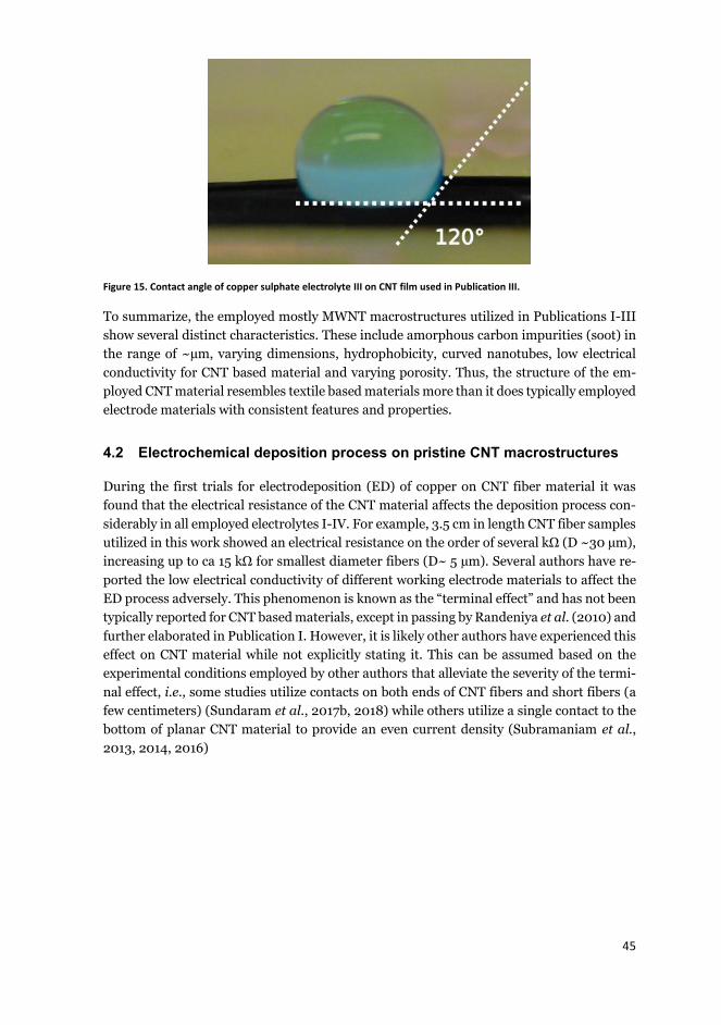
45
Figure 15. Contact angle of copper sulphate electrolyte III on CNT film used in Publication III.
To summarize, the employed mostly MWNT macrostructures utilized in Publications I-III show several distinct characteristics. These include amorphous carbon impurities (soot) in the range of ~μm, varying dimensions, hydrophobicity, curved nanotubes, low electrical conductivity for CNT based material and varying porosity. Thus, the structure of the em-ployed CNT material resembles textile based materials more than it does typically employed electrode materials with consistent features and properties.
4.2 Electrochemical deposition process on pristine CNT macrostructures
During the first trials for electrodeposition (ED) of copper on CNT fiber material it was found that the electrical resistance of the CNT material affects the deposition process con-siderably in all employed electrolytes I-IV. For example, 3.5 cm in length CNT fiber samples utilized in this work showed an electrical resistance on the order of several kΩ (D ~30 μm), increasing up to ca 15 kΩ for smallest diameter fibers (D~ 5 μm). Several authors have re-ported the low electrical conductivity of different working electrode materials to affect the ED process adversely. This phenomenon is known as the “terminal effect” and has not been typically reported for CNT based materials, except in passing by Randeniya et al. (2010) and further elaborated in Publication I. However, it is likely other authors have experienced this effect on CNT material while not explicitly stating it. This can be assumed based on the experimental conditions employed by other authors that alleviate the severity of the termi-nal effect, i.e., some studies utilize contacts on both ends of CNT fibers and short fibers (a few centimeters) (Sundaram et al., 2017b, 2018) while others utilize a single contact to the bottom of planar CNT material to provide an even current density (Subramaniam et al., 2013, 2014, 2016)

46
In Figure 16, the polarization curves recorded at 50 mV/s for a highly conductive copper wire 100 μm in diameter and a CNT fiber sample 30 μm in diameter are shown. The differ-ence between the two materials is drastic; the overvoltage required to deposit copper on a CNT fiber is vastly larger than depositing on a Cu wire. The difference in polarization be-haviour is due to the high electrical resistance of the fiber.
Figure 16. Cathodic polarization curves of Cu wire and CNT fiber in Electrolyte I.
In this work, all the deposition tests aimed at producing CNT-Cu composite fibers and yarns were conducted by applying galvanostatic deposition. On all CNT fibers, yarns and films the deposition process was found to begin nearest the electrolyte-air interface where the ca-thodic polarization was largest. This result is due to the terminal effect caused by the high electrical resistance of the CNT macrostructures as discussed in Section 2.2. As copper was deposited further along the fiber the electroactive area was increased making further polar-ization over critical overpotential possible. Thus, all CNT macrostructures (up to 20 cm in length in case of CNT yarns) could be deposited with Cu as long as the deposition time was sufficient and copper deposition could reach the furthest points from the contact (Publica-tions I and II).
The terminal effect can be seen affecting the electrodeposition of Cu on a CNT fiber sample in Figure 17, where the copper nuclei population from Electrolyte I have been imaged at three distinct areas on the CNT fiber surface. The sample was deposited for a short time (60 s) at low applied current of -0.06 mA. Evidently, such a low deposition time was not suffi-cient to fully cover the fiber with copper as deposition ended ca. 0.5 cm away from the air-electrolyte interface. In Figure 17a, taken next to the electrolyte-air interface, the copper nuclei population density was estimated at ~50 nuclei/100 μm2. 2.2 mm further away from this point, Figure 17b, the nuclei population density had decreased to ~7 nuclei/100 μm2. In Figure 17c, taken 4.5 mm from the electrolyte-air interface, the last observable deposits were visible and the copper nuclei population density had dropped to 1.5 nuclei/100 μm2. Inter-estingly, at this point a cluster of copper nuclei had deposited. Thus, it can be concluded that due to the inhomogeneous nature of the CNT material, its electrochemical activity is not constant along the macrostructure surface and some parts of the fiber were more elec-trochemically active than others. This is likely due to variations in the degree of oxidation of the fiber, which occur during the high temperature production of CNT material as well as

47
variations in impurity distribution, including iron particles and amorphous carbon (Janas & Koziol, 2016). The average grain size on the surface of the fiber was found to be 1.6 μm irrespective of whether the air-electrolyte interface or parts further away were investigated. The lack of large variation in the nuclei size suggests that the observed nuclei were generated instantaneously during the beginning of the 60 s deposition test, but their population den-sity decreased due to losses in polarization. The conductivity of the CNT fiber during elec-trodeposition was improved, which enabled deposition further from the electrical contact.

48
Figure 17. Evolution of copper nuclei population density on CNT fiber at low deposition time (60s) and low current (-0.06 mA) at (a) close to current feed point, (b) 0.2 cm further and (c) 0.5 cm further from the current feed point (mod-ified from Publication I).

49
A transverse cross section of the fiber near the air-electrolyte interface was made by FIB milling, Figure 18. An accurate estimation of the Cu filling inside the CNT fiber is markedly difficult and is estimated qualitatively from SEM images (Sundaram et al., 2017a, 2017b, 2018). Interestingly, while the deposited copper on the surface of the fiber grew as distinctly separated nuclei, copper also covered individual CNTs and CNT bundles on the surface and inside of the fiber. Thus, copper was simultaneously depositing on the inside of the fiber and at the surface of the fiber to produce a continuous CNT-Cu structure and not just a cladding on the fiber surface. Considering the observed hydrophobic nature of the CNT film, which consists of thousands of CNT fibers, this result is surprising as it shows that the elec-trolyte is able to penetrate, atleast to some degree, inside the CNT fiber network.
Figure 18. Cross-section of CNT fiber after short deposition (60s) at low current (-0.06 mA).
During deposition, the pores between nanotubes and nanotube bundles that are the physi-cal pathways for new copper ions entering inside of the macrostructure are continuously closed due to the depositing copper closing off gaps inside the CNT fiber. For this reason, the applied current used by other authors producing a similar homogeneous mixture of CNT-Cu by ED onto an existing CNT network, is typically very low as it is assumed to in-crease the probability of superfilling the nanotube network with minimal porosity from the inside of the fiber to the surface. Surprisingly, in our tests the applied current did not appear to strongly affect the internal deposition of copper on CNT fibers – the interiors of samples were similarly deposited with Cu in a wide applied current range of -0.06 to -10 mA and at diameters from ca. 5 to 30 μm. The deposition of Cu on the inside of the fibers was estimated qualitatively from FIB milled cross-sections of the produced CNT-Cu composites (as re-ported in Publication I). In case there were large pores in the μm range on the inside of the fiber, similar to the pore shown in Figure 13a, they were typically not fully filled with copper. Such variation of the Cu deposit on the inside of the CNT network is likely to cause addi-tional electrical resistance of the composite, when compared with a continuous and non-porous Cu deposit.
Once the CNT fiber was fully coated, the Cu deposit followed the surface dimensions of the fiber underneath, Figure 19a. Therefore, for CNT fiber samples with even surface di-mensions the CNT-Cu diameter was consistent and for samples with uneven geometry, the diameter varied accordingly. The thickness of the copper coating on CNT fiber and yarn samples did not show considerable differences, likely as polarization became stable across the samples relatively quickly compared to the overall deposition time, similar to results by Randeniya et al. (2010) and Sundaram et al (2018). On some parts of the deposited fibers,

50
a considerable amount of amorphous carbon could be observed at the CNT-Cu fiber surface post deposition, Figure 19b, as amorphous carbon is highly electrically resistive and thus difficult to deposit with copper. The result is similar to those by Sundaram et al. (2017b), who reported uncoated “black spots” after deposition on some of their CNT-Cu samples. The Cu cladding in Figure 19c shows columnar growth, typical of compact Cu electrodepos-its (Paunovic & Schlesinger, 2006). The grain size difference between the Cu cladding and inside the fiber can be explained by the depletion of copper ions inside the fiber as copper ions have to diffuse through the CNT material. Grujicic et al. (2002) have shown that smaller copper concentration leads to smaller and densely distributed nuclei. A similar ob-servation of the grain size of copper on the inside of CNT macrostructures and on the clad-ding been reported for electrodeposited CNT-Cu by many authors (Yang et al., 2008; Sundaram et al., 2017a, 2017b; Chen et al., 2018a; Rho et al., 2018).
Figure 19. Representative images of CNT-Cu fibers after deposition with Cu (a) surface morphology and (b) amorphous carbon contamination and (c) cross-section (Publication I).
In Figure 20, the deposition current used in creating 3.5 cm long CNT-Cu fibers (D =~10 μm) is plotted against the recorded stable electrode potential (V vs. Cu/CuSO4 reference electrode) during deposition and the time (s) it took to fully cover the surface of the fiber with copper. The high potentials during deposition are attributed to the high electrical re-sistance of the CNT material. In order to force the copper deposition on CNT fiber samples the required potentials were quite high as shown previously in Figure 16. Due to the previ-ously mentioned variation in the electrical conductivity of the samples, the reproducibility between different samples was difficult as the polarization behaviour was not constant.

51
Figure 20. Deposition current plotted against the stable electrode potential at the end of the experiment and the time (s) it took to cover the fiber with copper. Sample length was a constant 3.5 cm and the diameter of the fiber was estimated to be 10 μm.
The change in resistance of CNT-Cu fibers after electrodeposition was studied by depositing CNT fibers of ~30 μm diameter and 11 cm length with varying deposition times, Figure 21. The applied current was -10 mA. The whole fiber length was covered with copper during all deposition times. The strong de-crease in resistance after the fiber has been coated with copper shows the drastic difference between the conductivity of pristine CNT material and copper. Once the CNT fiber has been coated with copper, the decrease in electrical resistance becomes considerably smaller as the conductivity is dominated by the growing copper cladding.
Figure 21. Resistance of CNT-Cu fiber after electrodeposition for different times at -10 mA on 30 μm diameter CNT fiber.
The deposition of Cu on CNT yarns was also studied (Publications I & II). The CNT yarns were produced by manual rolling from CNT film and had considerably larger diameters than
0.0 0.5 1.0 1.5 2.00.0
-0.5
-1.0
-1.5
-2.0
-2.5
-3.0
Electrode potential Time
Deposition current (mA)
Elec
trode
pot
entia
l (V
vs. C
u/C
uSO
4)
200
400
600
800
1000
1200
1400
Tim
e (s
)

52
individual fibers, from ca. 50 to 150 μm, depending on the width of film rolled. The yarns were then densified by spraying with acetone that induced bundling of the CNTs and thus lowered the porosity and increased the density of the material (estimated at ca. 1 g cm-3). Due to the larger dimensions, this material was easier to handle and had electrical resistance orders of magnitude smaller than CNT fibers. These yarns could be deposited with a copper cladding in Electrolyte II in a wide range of applied cathodic current values (from -0.2 to -40 mA), Figure 22a. At the lowest cathodic current values the deposition time for CNT yarns was around 20 hours, while the higher deposition rates could coat the yarn in minutes. However, deposition of copper to the inside of the yarns was considerably more difficult. Copper was deposited inside the CNT yarn networks only at very low applied current (in the range of -0.2 to -2 mA), but only as individual copper grains that did not form a continuous mixture with CNTs. A more recent report by Sundaram et al. (2018) showed a similar trend of decreasing Cu deposition to the inside of increasingly dense CNT macrostructures (from 0.5 to 1.1 g cm-3), even when utilizing 2-step electrodeposition with both organic and aque-ous electrolytes.
In an attempt to overcome this issue, the deposition inside the CNT yarns was enhanced by utilizing additives in the electrolyte (Electrolyte IV) and very low deposition current (in the range of -0.2 to -2 mA), while applying solution stirring with a magnetic stirrer at 400 rpm. With this process the deposition of copper to the inside of the yarn was considerably enhanced (see Figure 22b, where the CNT-Cu yarn sample was cut with a surgical blade). In this case the copper penetration inside the wire could be considerably enhanced compared with depositing just a Cu cladding. However, the Cu deposit penetration inside the high density CNT yarn could not be made continuous in similar fashion as with lower density CNT fibers. The typical surface structure of CNT-Cu yarn is shown in Figure 22c. The im-proved electrodeposition of Cu to the inside of CNT networks at low current (Subramaniam et al., 2013; Sundaram et al., 2017b, 2018; Tao et al., 2017) and by utilizing additives (Tao et al., 2017; Chen et al., 2018a) in the electrolyte has been noted by several authors from both aqueous and organic electrolytes.
Figure 22. Morphology of CNT-Cu yarns (a) CNT yarn core and Cu cladding, (b) continuous composite of CNT-Cu and (c) surface structure.

53
The previously shown hydrophobic nature of pristine CNT structures is more pronounced when electrodepositing onto planar CNT films than when depositing on yarns and fibers. This effect could be related to the considerably larger planar area of the CNT film when compared with that of small diameter fibers and yarns. The hydrophobicity affects both the deposition on the material surface and the penetration of copper ions to the inside of the material. When depositing onto a CNT film, the electrolyte can not effectively cover the whole surface. The result of this effect can be observed when depositing on pristine CNT film samples, Figure 23. Here, large areas of the CNT film have no discernible copper nu-cleation when depositing from Electrolyte III, while other areas of the surface have a thick copper cladding. In Figure 23a, the sample was deposited at - 3.8 mA cm-2 for 1800s and the resulting grain size of copper deposits was 10.1 μm with s.d. 4.1 m. In Figure 23b an-other sample was deposited at -5 mA cm-2 for 3600 s. Even at such long deposition times the film surface could only be partially covered by the deposit. The deposition of Cu on pris-tine CNT films was limited to the surface and no Cu could be seen penetrating inside the CNT films.
Figure 23. Pristine CNT films after deposition at (a) -3.8 mA cm-2 for 1800s and (b) 5 mA cm-2 3600s.
To summarize, the electrochemical deposition process is reported to be highly affected by the characteristics of the employed nanotube macrostructures (Publications I-III). Due to the low electrical conductivity of the CNT material, the required polarization for copper deposition is considerably higher than for substrates of metallic conductivity. The terminal effect reported in Publication I is found to disable the electrochemical deposition process of copper beyond a short distance from the electrical contact. However, at long deposition times the low density CNT material (~0.7 g cm-3) can be deposited with copper both on the CNT material surface and inside of the nanotube network (Publication I). The copper de-posit morphology follows the features of the CNT material. Higher density CNT material (~1 g cm-3) can only be deposited with a copper cladding and minimal deposition of Cu on the inside of the CNT network from similar conditions (Publication II). To improve the dep-osition on the inside of the dense nanotube network a very low applied polarization, stirring during deposition and additives in the electrolyte are required. Once the CNT material sur-face has been fully deposited the electrical resistance is decreased by 3-4 orders of magni-tude due to the highly conductive continuous layer of copper (Publication I and II). Due to the hydrophobicity of planar CNT films, the material can only be deposited unevenly on its surface, with no penetration of Cu to the CNT network (Publication III).

54
4.3 Electrochemical deposition process on functionalized CNT macrostruc-tures
Due to the as-produced CNT material showing different issues as outlined before, such as carbonaceous impurities, electrochemical inhomogenuity and hydrophobicity, a pre-treat-ment method was studied in order to alleviate these problems (Publication III). It is well known that oxidative treatments introduce various surface functionalities, such as atomic oxygen, carboxyl and hydroxyl (Wildgoose et al., 2006; Datsyuk et al., 2008), which en-hance the surface activity of CNT material for metal deposition by various methods (Kim & Sigmund, 2004; Felten et al., 2006). Grafting oxygen containing functional groups on CNT materials has also been shown to improve hydrophilicity, while removing carbonaceous im-purities (Pavese et al., 2008; Dichiara et al., 2015). Thus, two different types of oxidative pre-treatments were investigated, i.e., heat treatment in furnace and electro-oxidation, and the resulting change in functionalization was detected by Raman spectroscopy, by compar-ison of the ID/IG ratio of CNT material after a pre-treatment. In Figure 24, the ID/IG ratios of pristine and functionalized CNT film samples are shown. There is a trend of increasing the level of functionalization by increasing the furnace temperature or the electro-oxidation (termed anodization in the image) voltage. In general, the heat treatment produced a milder level of functionalization compared to the electro-oxidation treaments.
Figure 24. Degree of functionalization by different functionalization treatments (Publication III).
The oxidation treatment affected the CNT properties and microstructure considerably, even at low levels of functionalization by heat treatment. A visible difference was observed at the CNT film surface after even the mildest functionalization; the amorphous carbon particles were largely removed. Furthermore, when attempting to repeat the contact angle measure-ment with Electrolyte III, the material exhibited such hydrophilicity that no contact angle could be discerned even from the mildly functionalized samples. However, with an im-proved apparatus for this measurement a (small) value could possibly have been obtained. After heavily functionalizing the CNT film at 2.2 V vs. SCE for 60 seconds, the deposition test shown in Figure 23a was repeated and a noticeable difference could be observed as shown in Figure 24.

55
Figure 25. Functionalized CNT film after deposition at -3.8 mA cm-2 for 1800s. Functionalization by electro-oxidation at 2.2 V vs. SCE for 60s. Publication III.
The nuclei density of copper was highly affected by the functionalization treatment. Even small areas without copper nucleation could not be observed on the functionalized sample. The average grain size was 6.5 μm with s.d. 2.1 μm, while the nuclei population density was homogeneous indicating a higher and more even nucleation rate compared to the non-func-tionalized surface in Figure 23a. The increase in copper nuclei population density and de-crease in nuclei size in functionalized CNT films is assumed to be due to the effect of func-tional groups at the CNT film surface. These functional groups have a higher binding energy to copper than the pristine CNT structure (Park et al., 2011) and thus the diffusing adatoms get trapped near the oxygen functionalized groups causing the nucleation density to in-crease as previously noted in thermal evaporation and sputtering studies (Felten et al., 2006; Gopee et al., 2016). A similar trend of increasing Cu nuclei population density and decreasing the nuclei size has also been reported previously for a heat treated carbon fiber coated by electrodeposition from a similar copper sulphate electrolyte (Li et al., 2011).
The electrochemical activity of CNT films was also studied by cathodic polarization curves, as shown previously for a CNT fiber and Cu wire in Figure 16. In this experiment, presented in Figure 26, a cathodic polarization curve was recorded for a CNT film sample in Electrolyte III. The sample was then electro-oxidized in 1 M H2SO4 for 60s to remove the deposited copper and functionalize the CNT film surface and a new cathodic polarization curve in the copper sulphate electrolyte was recorded. This procedure was then repeated at increasing electro-oxidation voltages, beginning from 1.2 V up to 2.2 V. The considerably higher cur-rent passing through the pristine CNT film compared with a single CNT fiber (in Figure 16) is due to the higher electrical conductivity of CNT films formed of multiple CNT fibers. The electro-oxidation procedure clearly increased the electrochemical activity of the CNT film in each successive functionalization treatment, until oxidation at 1.8 V vs. SCE, similar to the results obtained by Li et al. (2011) on oxidized carbon fibers. Increasing the oxidation level of the CNT film beyond this level visibly began to detach some CNT material from the film. At this point, the polarization of the CNT film began to decrease, likely due to increased electrical resistance caused by the excessive functionalization which deteriorated the CNT film structure.

56
Figure 26. Cathodic polarization of CNT film in Electrolyte III after electro-oxidation at various voltages in 1M H2SO4 (Publication III).
To summarize, the employed CNT films can be functionalized to various degrees by control-ling the oxidation conditions when utilizing electro-oxidation and heat treatment (Publica-tion III). The effect of functionalization is drastic on the CNT film surface; the material be-comes hydrophilic, while carbonaceous impurities are removed. Due to the introduction of oxygen containing functional groups, such as carboxyl and hydroxyl, at the surface of nano-tube film, the electrochemical activity of the macrostructure is found to be considerably en-hanced. This is attributed to the functional groups acting as nucleation centers, as previ-ously reported in literature for functionalized CNT material deposited with thermal evapo-ration and sputtering. However, under severe oxidation conditions the CNT film begins to deteriorate, which can be seen as a decrease in the cathodic polarization of the material in copper sulphate electrolyte.
4.4 Specific electrical conductivity of CNT-Cu composites by electrodepo-sition
As shown previously, the diameter of CNT fiber/yarn and therefore the resultant CNT-Cu composite cross-sections vary along their length. For this reason, the electrical conductivity of the produced composite samples (Publication I and II) could not be accurately normal-ized by use of the cross-section. Instead, electrical conductivity by weight, i.e., specific con-ductivity as shown in equation (3), was used as it is an exact and comparable property for each sample. With this comparison, the attractive low weight (and also density) of CNT based Cu composites could also be elaborated. The results in Figure 27 are for non-func-tionalized CNT fiber (Electrolyte I, Publication I) and yarn (Electrolyte II, Publication II) samples after electrodeposition with copper. In addition, the figure presents also some re-sults from literature of electrodeposited CNT-Cu. Literature results by powder metallurgy methods have mostly been omitted as they consistently show values lower than pure Cu even at very low CNT loading. The difference in the change in specific conductivity between fiber and yarn based CNT-Cu composites is obvious. This is attributed to the fact that the morphology of copper deposits on CNT yarns and fibers are vastly different. On fibers (de-posited from Electrolyte I) the penetration of copper on the inside of the fiber network is
-1.0 -0.8 -0.6 -0.4 -0.2 0.0-30
-20
-10
0
Pristine1.2 V1.4 V1.6 V1.8 V2.0 V2.2 V
j (m
A c
m-2
)
E (V vs. SCE)
Electro-oxidation increasesactivity until 1.8V

57
high as shown in Figure 18. Conversely, from a similar electrolyte without additives (Elec-trolyte II), the majority of the copper was deposited as a cladding on the surface of the yarns and did not penetrate inside the yarn, as shown in Figure 22a.
Based on the results shown in Figure 27, the deposition of copper to the inside of the em-ployed CNT material, or as a separate cladding did not enhance the specific electrical con-ductivity of the material beyond pure copper. However, some differences in specific con-ductivity of the various CNT-Cu composite samples can be discerned. The higher specific conductivity of CNT-Cu yarns at a given CNT wt% is attributed to their structure. In these samples the copper mostly existed as a cladding on the surface of CNT yarns (shown in Fig-ure 22a). Therefore, the conductivity of CNT-Cu yarns was dominated by the pure copper cladding with minimal contribution from the small amount of Cu from inside the electrically resistive CNT network. Conversely, for the CNT-Cu fibers, a contribution to the electrical resistance also comes from the electron scattering inside the CNT-Cu network. Inside the CNT fiber the Cu exists as small grains that are not continuous similarly as in the Cu clad-ding. Furthermore, the CNT-CNT junctions and CNT-Cu junctions are also likely to increase the electron scattering. The amorphous carbon impurities on the employed CNT material also negatively affect the electrical conductivity of the composite (Lekawa-Raus et al., 2014). As the CNT material in fibers and yarns consists of the same type of nanotubes, these results further elaborate the effect of the CNT macrostructure on the produced CNT-Cu structure and the resulting specific conductivity, when the CNTs are either embedded in a Cu matrix or covered with a Cu cladding. A vast majority of the research on Cu deposition onto com-parable CNT macrostructures has yielded specific conductivity lower than Cu (Randeniya et al., 2010, Xu et al., 2011; Shuai et al., 2016; Sun et al., 2016; Sundaram et al., 2017a, 2017b, 2018, Chen et al., 2018a; Han et al., 2018; Tao et al., 2018; Zou et al., 2018), no matter the degree of penetration to the inside of the CNT network.
The most impressive results published by Subramaniam et al. (2013) and Yang et al. (2008), have shown increased specific conductivity (up to 26 % higher than pure Cu) of CNT-Cu films. The critical differences between the CNT-Cu produced in this work and in the above mentioned studies is in the type of CNTs and the structure of the produced CNT-Cu. Firstly, the CNT material before deposition by Yang et al. (2008) and Subramaniam et al. (2013) consist of high purity (99%) SWNTs that are embedded in the Cu matrix with a minimal amount of contacts between nanotubes, i.e., the nanotubes exist mostly separate inside the Cu matrix and are not bundled considerably. The alignment of nanotubes in the employed mostly MWNT networks and their curved nature in this work is another critical difference. This reasoning is further supported by results from the same group of Subrama-niam et al. (2013), who produced CNT-Cu fibers by electrodeposition (Sundaram et al., 2018) onto MWNT fibers of similar dimensions than the samples employed in this work. The reported structure of their composite was similar to the CNT-Cu fibers produced in this work. In this case, the reported specific electrical conductivity of their CNT-Cu follows the same trend as the CNT-Cu fiber results of this work as shown in Figure 27. Thus, it can be concluded that to improve the specific electrical conductivity of CNT-Cu materials, some criteria have to be met; the nanotubes need to be straight, highly conductive SWNT that are aligned in the axial direction of the composite with minimal bundling between individual CNTs.
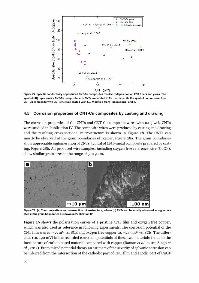
58
Figure 27. Specific conductivity of produced CNT-Cu composites by electrodeposition on CNT fibers and yarns. The symbol ( ) represents a CNT-Cu composite with CNTs embedded in Cu matrix, while the symbol (▲) represents a CNT-Cu composite with CNT structure coated with Cu. Modified from Publications I and II.
4.5 Corrosion properties of CNT-Cu composites by casting and drawing
The corrosion properties of Cu, CNTs and CNT-Cu composite wires with 0.05 wt% CNTs were studied in Publication IV. The composite wires were produced by casting and drawing and the resulting cross-sectional microstructure is shown in Figure 28. The CNTs can mostly be observed at the grain boundaries of copper, Figure 28a. The grain boundaries show appreciable agglomeration of CNTs, typical of CNT-metal composite prepared by cast-ing, Figure 28b. All produced wire samples, including oxygen free reference wire (CuOF), show similar grain sizes in the range of 5 to 9 μm.
Figure 28. (a) The composite wire cross-section microstructure, where (b) CNTs can be mostly observed as agglomer-ated at the grain boundaries as shown in Publication IV.
Figure 29 shows the polarization curves of a pristine CNT film and oxygen free copper, which was also used as reference in following experiments. The corrosion potential of the CNT film was ca. -55 mV vs. SCE and oxygen free copper ca. –245 mV vs. SCE. The differ-ence (ca. 190 mV) in the recorded corrosion potentials of these two materials is due to the inert nature of carbon based material compared with copper (Raman et al., 2012; Singh et al., 2013). From mixed potential theory an estimate of the severity of galvanic corrosion can be inferred from the intersection of the cathodic part of CNT film and anodic part of CuOF

59
at ca. 4 μA/cm2. It has to be noted that due to the observed hydrophobicity of the CNT ma-terial and the porous nature of the CNT film, the actual CNT surface area that was in contact with the electrolyte is not the geometrical surface area that was used in the approximation of the current density. Therefore this value is only an estimation, however, this has no effect on the observed corrosion potentials of the two dinstinctly different materials. It should also be noted that the CNT film also has some impurities, such as Fe and amorphous carbon that can influence the polarization behaviour. The removal of impurities was not attempted as this would also functionalize the CNT film as shown in Figure 24.
Figure 29. Polarization curves of oxygen free copper (CuOF) and carbon nanotube (CNT) film in 3.5 wt% NaCl for galvanic current density estimation (Publication IV).
Figure 30 shows the polarization curves of CuOF reference and four different composite wires (A, B, C and D). Sample D showed the highest corrosion potential (- 209 mV vs. SCE), while CuOF and other samples had values close to each other (-236 to -251 mV vs. SCE). In all of the composite samples, the cathodic current density was lower than that of pure cop-per, while the anodic behaviour of the samples did not show any appreciable differences. This is in contrast to the results by Raman et al. (2012), who showed an increase in the corrosion potential and a decrease in both the anodic and cathodic reactions on graphene coated Cu. This is perhaps not surprising, as in our case the solution is in contact with both CNTs and Cu, while in their case it is expected that the graphene effectively insulates the copper underneath by acting as an ionic barrier.

60
Figure 30. Polarization curves of CuOF and CNT-Cu samples A-D in solution II (3.5 wt% NaCl), inset of cathodic slope. (Publication IV)
The long-term corrosion measurement data from linear polarization measurements (LPR) are shown in Figure 31. Here, the samples were tested by LPR for atleast ca. 37 h, when the samples exhibited stable performance. The corrosion current density was then calculated with equation (4) from the recorded corrosion resistance. All composite samples showed lower corrosion current density (up to 50 % less than the CuOF reference material) after a period of ca. 20 h. While indicative of the positive role of the nanotubes in this composite structure in terms of corrosion, these differences in corrosion current density are quite small compared with carbon based coatings on Cu (Kirkland et al., 2012; Raman et al., 2012; Singh et al., 2013). A similar result was reported by Kamboj et al. (2017) who produced a graphene-Cu coating on steel that showed a decrease of corrosion current by 56 % compared with the pure Cu coating. Considering the small amount of CNTs (0.05 wt%) embedded in the copper matrix, a study on the same type of CNT-Cu wire with embedded nanotubes at a higher concentration should clarify the effect of CNTs further.
Figure 31. Corrosion current density recorded every 30 minutes in solution II (3.5 wt% NaCl) for CuOF and CNT-Cu
samples A-D (Publication IV).

61
5. Conclusions
This thesis reports the factors affecting the electrochemical deposition of copper onto car-bon nanotube (CNT) macrostructures from aqueous copper sulphate electrolytes. The struc-ture of the CNT macrostructure affected both the deposition process and the penetration of copper to the inside of the CNT network. Based on the characteristics of pristine CNT macrostructures, different oxidative pre-treatment methods were also studied and their ef-fect on the electrochemical deposition process reported. The microstructure of the produced carbon nanotube-copper composite structures was characterized and their specific electri-cal conductivity values were compared with the literature. To assess the practical applica-bility of the CNT-Cu composite conductors, the corrosion behaviour of cast and drawn car-bon nanotube-copper composite wires was also studied among one of the first reports in literature. The following conclusions can be made based on the presented results:
The electrochemical deposition process of copper on CNT macrostructures from copper sulphate electrolytes is found to be affected to a large degree by the inher-ent properties of the employed CNT material, such as volumetric density, electrical conductivity, hydrophobicity and presence of impurities. The effect of the low elec-trical conductivity of the CNT material (~300 S/cm) is reported to cause drastic losses in polarization as the distance from the electrical contact increases. How-ever, at long enough deposition times copper can be deposited evenly on the CNT material as polarization becomes homogeneous.
The electrochemical response of planar CNT film can be improved by oxidative pre-treatments, which reduce the amount of impurities on the material, while grafting oxygen containing functional groups at the nanotube surfaces. These ox-ygen containing groups are found to increase the electrochemical activity of the CNT material, while also making the material hydrophilic. However, it was found that for drastic levels of functionalization the film begins to degrade and polariza-tion decreases. Thus, the effect of different degrees of functionalization was re-ported to have a direct effect on the electrodeposition process of copper.
Increasing the CNT macrostructure density from ca. 0.7 g cm-3 to ca. 1 g cm-3 de-creased the copper penetration inside the dense CNT yarns, which caused copper to deposit mostly as a cladding on top of the CNT macrostructure. However, the deposition inside the dense CNT macrostructure could be enhanced considerably by the use of additives in the electrolyte, utilizing a minimal deposition current and applying stirring during deposition.
While functionalization up to a certain degree improves the electrochemical dep-osition of Cu onto CNT macrostructures, its effect on the properties of CNT-Cu

62
needs to be elaborated due to its wide ranging effects on the properties of individ-ual CNTs and the CNT/Cu interface. At the minimum, a mild functionalization treatment by, e.g., heat treatment, is suggested for purification of CNT material from carbonaceous impurities before deposition of Cu.
The specific electrical conductivity of the produced CNT-Cu composites is found to be dependent on the penetration of copper to the inside of the CNT macrostruc-ture. For samples with only a copper cladding, the specific electrical conductivity is higher than for samples at the same CNT wt%, where the copper has deposited inside the CNT macrostructure. When copper deposits inside the CNT macrostruc-ture the deterioration in electrical conductivity is attributed to the small grain Cu deposit and scattering of electrons at the CNT/CNT and CNT/Cu interfaces.
Based on the results, to produce a CNT-Cu with specific conductivity higher than pure copper, some pre-requisites are needed. The use of low density CNT macro-structures (< 0.7 g cm-3) is required as they can be easily deposited with copper to fully cover the nanotube surfaces to form a continuous mixture of CNTs and Cu. The CNT macrostructure needs to be formed of long metallic single wall nanotubes aligned in the parallel direction with minimal amount of CNT to CNT contacts, i.e., bundling, so that a CNT-Cu composite of high electrical conductivity can be formed. Furthermore, in order to produce a continuous and uniform CNT-Cu com-posite by electrodeposition, the porosity of the CNT macrostructure needs to be uniform, so that the deposition inside the CNT network can achieve a homogene-ous mixture of CNTs and Cu. These requirements are at odds with the current de-velopment trends in CNT macrostructures, which are typically not tailored for composite production and are rather focused on the production of highly dense CNT materials.
The corrosion performance of copper embedded with 0.05 wt% multiwall nano-tubes at the grain boundaries was similar or slightly improved over pure copper. Promisingly, no galvanic corrosion could be detected between the Cu matrix and CNTs. To further probe these novel findings, the effect of embedded CNTs on the corrosion of copper, the corrosion behaviour of a CNT-Cu wire with an order of magnitude higher amount of CNTs should be studied.

63
References
Alkire, R. & Varjian, R. 1974, "Resistive wire electrodes", Journal of the Electrochemical Society, vol. 121, no. 5, pp. 622-631.
Alvarenga, J., Jarosz, P.R., Schauerman, C.M., Moses, B.T., Landi, B.J., Cress, C.D. & Raf-faelle, R.P. 2010, "High conductivity carbon nanotube wires from radial densification and ionic doping", Applied Physics Letters, vol. 97, no. 18, pp. 182106-1-182106-3.
Arora, N. & Sharma, N.N. 2014, “Arc discharge synthesis of carbon nanotubes: Compre-hensive review”, Diamond and Related Materials, vol 50. pp. 135-150.
Aryasomayajula, L. & Wolter, K. 2013, "Carbon nanotube composites for electronic pack-aging applications: A Review", Journal of Nanotechnology, vol. 2013.
Balasubramanian, K. & Burghard, M. 2005, "Chemically functionalized carbon nano-tubes", Small, vol. 1, no. 2, pp. 180-192.
Bard, A., Stratmann, M., McDonald, D. & Schmuki, P. 2007, "Encyclopedia of Electro-chemistry, Electrochemical Engineering" vol. 5.
Behabtu, N., Young, C.C., Tsentalovich, D.E., Kleinerman, O., Wang, X., Ma, A.W., Bengio, E.A., ter Waarbeek, R.F., de Jong, J.J., Hoogerwerf, R.E., Fairchild, S.B., Ferguson, J.B., Maruyama, B., Kono, J., Talmon, Y., Cohen, Y., Otto, M.J. & Pasquali, M. 2013, "Strong, light, multifunctional fibers of carbon nanotubes with ultrahigh conductiv-ity", Science, vol. 339, no. 6116, pp. 182-186.
Birch, M.E., Ruda-Eberenz, T.A., Chai, M., Andrews, R. & Hatfield, R.L. 2013, "Properties that influence the specific surface areas of carbon nanotubes and nanofibers", Annals of occupational hygiene, vol. 57, no. 9, pp. 1148-1166.
Blech, I.A. 1976, "Electromigration in thin aluminum films on titanium nitride", Journal of Applied Physics, vol. 47, no. 4, pp. 1203-1208.
Budevski, E., Staikov, G. & Lorenz, W. 2000, "Electrocrystallization: nucleation and growth phenomena", Electrochimica Acta, vol. 45, no. 15-16, pp. 2559-2574.
CES EduPack software, Granta Design Limited, Cambridge, UK, 2018. www.gran-tadesign.com.
Cha, S.I., Kim, K.T., Arshad, S.N., Mo, C.B. & Hong, S.H. 2005, "Extraordinary strength-ening effect of carbon nanotubes in metal matrix nanocomposites processed by mo-lecular level mixing", Advanced Materials, vol. 17, no. 11, pp. 1377-1381.
Chai, G., Sun, Y. & Chen, Q. 2008a, "Mechanical properties of carbon nanotube–copper nanocomposites", Journal of Micromechanics and Microengineering, vol. 18, no. 3, pp. 035013.
Chai, Y., Chan, P.C., Fu, Y., Chuang, Y. & Liu, C. 2008b, "Copper/carbon nanotube compo-site interconnect for enhanced electromigration resistance", Electronic Components and Technology Conference, 2008. ECTC 2008. 58th IEEE, pp. 412.

64
Che, J., Cagin, T. & Goddard III, W.A. 2000, "Thermal conductivity of carbon nanotubes", Nanotechnology, vol. 11, no. 2, pp. 65.
Cheaptubes, 2018. Available at: www.cheaptubes.com, accessed 10.11.2018.
Chen, X., Tao, J., Yi, J., Liu, Y., Bao, R. & Li, C. 2018a, “Electrodeposited Cu/buckypaper composites with high electrical conductivity and ampacity”, Journal of Alloys and Compounds, vol. 735, pp. 163-171.
Chen, X., Tao, J., Yi, J., Liu, Y., Bao, R., Li, C., Tan, S. & You, X. 2018b, “Enhancing the strength of carbon nanotubes reinforced copper matrix composites by optimizing the interface structure and dispersion uniformity”, Diamond and Related Materials, vol. 88, pp. 74-84.
Chen, W., Tu, J., Wang, L., Gan, H., Xu, Z. & Zhang, X. 2003, "Tribological application of carbon nanotubes in a metal-based composite coating and composites", Carbon, vol. 41, no. 2, pp. 215-222.
Cheng, B., Bao, R., Yi, J., Li, C., Tao, J., Liu, Y., Tan, S. & You, X. 2017, “Interface optimi-zation of CNT/Cu composite by forming TiC nanoprecipitation and low interface en-ergy structure via spark plasma sintering”, Journal of Alloys and Compounds, vol. 722, pp. 852-858.
Cho, S., Kikuchi, K. & Kawasaki, A. 2012, "On the role of amorphous intergranular and in-terfacial layers in the thermal conductivity of a multi-walled carbon nanotube–copper matrix composite", Acta Materialia, vol. 60, no. 2, pp. 726-736.
Cho, S., Kikuchi, K., Lee, E., Choi, M., Jo, I., Lee, S., Lee, S. & Kawasaki, A. 2017, "Chro-mium carbide/Carbon Nanotube Hybrid Structure Assisted Copper Composites with Low Temperature Coefficient of Resistance", Scientific reports, vol. 7, no. 1, pp. 14943.
Cho, S., Kikuchi, K., Miyazaki, T., Takagi, K., Kawasaki, A. & Tsukada, T. 2010, "Multi-walled carbon nanotubes as a contributing reinforcement phase for the improvement of thermal conductivity in copper matrix composites", Scripta Materialia, vol. 63, no. 4, pp. 375-378.
Chu, K., Jia, C., Jiang, L. & Li, W. 2013, "Improvement of interface and mechanical prop-erties in carbon nanotube reinforced Cu–Cr matrix composites", Materials & Design, vol. 45, pp. 407-411.
Chu, K., Wu, Q., Jia, C., Liang, X., Nie, J., Tian, W., Gai, G. & Guo, H. 2010, "Fabrication and effective thermal conductivity of multi-walled carbon nanotubes reinforced Cu matrix composites for heat sink applications", Composites Science and Technology, vol. 70, no. 2, pp. 298-304.
Colomer, J., Henrard, L., Van Tendeloo, G., Lucas, A. & Lambin, P. 2004, "Study of the packing of double-walled carbon nanotubes into bundles by transmission electron mi-croscopy and electron diffraction", Journal of Materials Chemistry, vol. 14, no. 4, pp. 603-606.
Copper Development Association Inc., 2018a, Copper Drives Electric Vehicles, Copper Al-liance. Available at: https://www.copper.org/publications/pub_list/pdf/A6191-Elec-tricVehicles-Factsheet.pdf, accessed 3.12. 2018.

65
Copper Development Association Inc., 2018b. Chromium Copper Overview. Available at: https://www.copper.org/resources/properties/microstructure/chrom_cu.html, ac-cessed 25.10.2018.
Dai, H., Wong, E.W. & Lieber, C.M. 1996, "Probing electrical transport in nanomaterials: conductivity of individual carbon nanotubes", Science, vol. 272, no. 5261, pp. 523-526.
Daoush, W.M., Lim, B.K., Mo, C.B., Nam, D.H. & Hong, S.H. 2009, "Electrical and me-chanical properties of carbon nanotube reinforced copper nanocomposites fabricated by electroless deposition process", Materials Science and Engineering: A, vol. 513, pp. 247-253.
Datsyuk, V., Kalyva, M., Papagelis, K., Parthenios, J., Tasis, D., Siokou, A., Kallitsis, I. & Galiotis, C. 2008, "Chemical oxidation of multiwalled carbon nanotubes", Carbon, vol. 46, no. 6, pp. 833-840.
Deng, H., Yi, J., Xia, C. & Yi, Y. 2017, "Mechanical properties and microstructure charac-terization of well-dispersed carbon nanotubes reinforced copper matrix composites", Journal of Alloys and Compounds, vol. 727, pp. 260-268.
Dichiara, A.B., Webber, M.R., Gorman, W.R. & Rogers, R.E. 2015, "Removal of copper ions from aqueous solutions via adsorption on carbon nanocomposites", ACS Applied Materials & Interfaces, vol. 7, no. 28, pp. 15674-15680.
Dong, S., Tu, J. & Zhang, X. 2001, "An investigation of the sliding wear behavior of Cu-matrix composite reinforced by carbon nanotubes", Materials Science and Engineer-ing: A, vol. 313, no. 1-2, pp. 83-87.
Duan, Z., Liu, D., Zhang, G., Li, Q., Liu, C. & Fan, S. 2017, "Interfacial thermal resistance and thermal rectification in carbon nanotube film-copper systems", Nanoscale, vol. 9, no. 9, pp. 3133-3139.
Ebbesen, T., Lezec, H., Hiura, H., Bennett, J., Ghaemi, H. & Thio, T. 1996, "Electrical con-ductivity of individual carbon nanotubes", Nature, vol. 382, no. 6586, pp. 54.
Felten, A., Bittencourt, C. & Pireaux, J. 2006, "Gold clusters on oxygen plasma functional-ized carbon nanotubes: XPS and TEM studies", Nanotechnology, vol. 17, no. 8, pp. 1954.
Firkowska, I., Boden, A., Vogt, A. & Reich, S. 2011, "Effect of carbon nanotube surface modification on thermal properties of copper–CNT composites", Journal of Materi-als Chemistry, vol. 21, no. 43, pp. 17541-17546.
Ghanbari, S. & Darabi, J. 2015, "Fabrication and material characterization of copper and copper–CNT micropillars", Materials Research Express, vol. 2, no. 7, pp. 075501.
Gopee, V., Thomas, O., Hunt, C., Stolojan, V., Allam, J. & Silva, S. 2016, "Carbon nanotube interconnects realized through functionalization and sintered silver attachment", ACS Applied Materials & Interfaces, vol. 8, no. 8, pp. 5563-5570.
Grujicic, D. & Pesic, B. 2002, "Electrodeposition of copper: the nucleation mechanisms", Electrochimica Acta, vol. 47, no. 18, pp. 2901-2912.

66
Gspann, T.S., Juckes, S.M., Niven, J.F., Johnson, M.B., Elliott, J.A., White, M.A. & Windle, A.H. 2017, "High thermal conductivities of carbon nanotube films and micro-fibres and their dependence on morphology", Carbon, vol. 114, pp. 160-168.
Guiderdoni, C., Pavlenko, E., Turq, V., Weibel, A., Puech, P., Estournès, C., Peigney, A., Bacsa, W. & Laurent, C. 2013, “The preparation of carbon nanotube (CNT)/copper composites and the effect of the number of CNT walls on their hardness, friction and wear properties”, Carbon, vol. 58, pp. 185-197.
Han, B., Guo, E., Xue, X., Zhao, Z., Li, T., Xu, Y., Luo, L. & Hou, H. 2018, “Fabricating and strengthening the carbon nanotube/copper composite fibers with high strength and high electrical conductivity”, Applied Surface Science, vol. 441. pp. 984-992.
Harper, J., Cabral Jr, C., Andricacos, P., Gignac, L., Noyan, I., Rodbell, K. & Hu, C. 1999, "Mechanisms for microstructure evolution in electroplated copper thin films near room temperature", Journal of Applied Physics, vol. 86, no. 5, pp. 2516-2525.
Hasegawa, M., Negishi, Y., Nakanishi, T. & Osaka, T. 2005, "Effects of additives on copper electrodeposition in submicrometer trenches", Journal of the Electrochemical Soci-ety, vol. 152, no. 4, pp. C221-C228.
Hjortstam, O., Isberg, P., Söderholm, S. & Dai, H. 2004, "Can we achieve ultra-low resis-tivity in carbon nanotube-based metal composites?", Applied Physics A, vol. 78, no. 8, pp. 1175-1179.
Hone, J., Llaguno, M., Nemes, N., Johnson, A., Fischer, J., Walters, D., Casavant, M., Schmidt, J. & Smalley, R. 2000, "Electrical and thermal transport properties of mag-netically aligned single wall carbon nanotube films", Applied Physics Letters, vol. 77, no. 5, pp. 666-668.
Huang, J., Chen, S., Wang, Z., Kempa, K., Wang, Y., Jo, S., Chen, G., Dresselhaus, M. & Ren, Z. 2006, "Superplastic carbon nanotubes", Nature, vol. 439, no. 7074, pp. 281.
Huang, Z., Zheng, Z., Zhao, S., Dong, S., Luo, P. & Chen, L. 2017, "Copper matrix compo-sites reinforced by aligned carbon nanotubes: Mechanical and tribological proper-ties", Materials & Design, vol. 133, pp. 570-578.
ITRS, International Technology Working Groups, International Technology Roadmap for Semiconductors: 2015, http://www.itrs.net, accessed 25.5.2015.
Jakubinek, M.B., White, M.A., Li, G., Jayasinghe, C., Cho, W., Schulz, M.J. & Shanov, V. 2010, “Thermal and electrical conductivity of tall, vertically aligned carbon nanotube arrays”, Carbon, vol. 48. pp. 3947-3952.
Janas, D. & Koziol, K.K. 2016, "Carbon nanotube fibers and films: synthesis, applications and perspectives of the direct-spinning method", Nanoscale, vol. 8, no. 47, pp. 19475-19490.
Janas, D., Kreft, S.K. & Koziol, K.K.K. 2017, “Printing of highly conductive carbon nano-tubes fibres from aqueous dispersion”, Materials & Design, vol. 116. pp. 16-20.
Jiang, H., Liu, B., Huang, Y. & Hwang, K. 2004, "Thermal expansion of single wall carbon nanotubes", Journal of engineering materials and technology, vol. 126, no. 3, pp. 265-270.

67
Josell, D., Wheeler, D., Witt, C. & Moffat, T.P. 2003, "Seedless superfill: copper electro-deposition in trenches with ruthenium barriers", Electrochemical and Solid-State Letters, vol. 6, no. 10, pp. C143-C145.
Kamboj, A., Raghupathy, Y., Rekha, M. & Srivastava, C. 2017, "Morphology, texture and corrosion behavior of nanocrystalline copper–graphene composite coatings", JOM, vol. 69, no. 7, pp. 1149-1154.
Kim, B. & Sigmund, W.M. 2004, "Functionalized multiwall carbon nanotube/gold nano-particle composites", Langmuir, vol. 20, no. 19, pp. 8239-8242.
Kim, K.T., Cha, S.I., Gemming, T., Eckert, J. & Hong, S.H. 2008, "The Role of Interfacial Oxygen Atoms in the Enhanced Mechanical Properties of Carbon Nanotube Rein-forced Metal Matrix Nanocomposites", Small, vol. 4, no. 11, pp. 1936-1940.
Kim, K.T., Cha, S.I. & Hong, S.H. 2007, "Hardness and wear resistance of carbon nano-tube reinforced Cu matrix nanocomposites", Materials Science and Engineering: A, vol. 449, pp. 46-50.
Kim, S.J., Shin, D.H., Choi, Y.S., Rho, H., Park, M., Moon, B.J., Kim, Y., Lee, S., Lee, D.S. & Kim, T. 2018, "Ultra-Strong Graphene-Copper Core-Shell Wires for High Perfor-mance Electrical Cables", ACS nano, vol. 12. pp. 2803-2808.
Kim, Y.J., Shin, T.S., Do Choi, H., Kwon, J.H., Chung, Y. & Yoon, H.G. 2005, "Electrical conductivity of chemically modified multiwalled carbon nanotube/epoxy composites", Carbon, vol. 43, no. 1, pp. 23-30.
Kim, K.T., Cha, S.I., Hong, S.H. & Hong, S.H. 2006, “Microstructures and tensile behavior of carbon nanotube reinforced Cu matrix nanocomposites”, Materials Science and Engineering: A, vol. 430, pp. 27-33.
Kim, K.T., Eckert, J., Liu, G., Park, J.M., Lim, B.K. & Hong, S.H. 2011, “Influence of em-bedded-carbon nanotubes on the thermal properties of copper matrix nanocompo-sites processed by molecular-level mixing”, Scripta Materialia, vol. 64, pp. 181-184.
Kirkland, N., Schiller, T., Medhekar, N. & Birbilis, N. 2012, "Exploring graphene as a cor-rosion protection barrier", Corrosion Science, vol. 56, pp. 1-4.
Koziol, K., Vilatela, J., Moisala, A., Motta, M., Cunniff, P., Sennett, M. & Windle, A. 2007, "High-performance carbon nanotube fiber", Science, vol. 318, no. 5858, pp. 1892-1895.
Kwaśniewski, P. & Kiesiewicz, G. 2014, "Studies on obtaining Cu-CNT composites by con-tinuous casting method", Metallurgy and Foundry Engineering, vol. 40, no. 2, pp. 83-92.
Laha, T., Agarwal, A., McKechnie, T. & Seal, S. 2004, "Synthesis and characterization of plasma spray formed carbon nanotube reinforced aluminum composite", Materials Science and Engineering: A, vol. 381, no. 1-2, pp. 249-258.
Lee, J., Berrada, S., Adamu-Lema, F., Nagy, N., Georgiev, V.P., Sadi, T., Liang, J., Ramos, R., Carrillo-Nunez, H. & Kalita, D. 2018, "Understanding Electromigration in Cu-CNT Composite Interconnects: A Multiscale Electrothermal Simulation Study", IEEE Transactions on Electron Devices, vol. 65, no. 9, pp. 3884-3892.

68
Lehman, J.H., Terrones, M., Mansfield, E., Hurst, K.E. & Meunier, V. 2011, “Evaluating the characteristics of multiwall carbon nanotubes”, vol. 49, pp. 2581-2602.
Lekawa Raus, A., Patmore, J., Kurzepa, L., Bulmer, J. & Koziol, K. 2014, "Electrical prop-erties of carbon nanotube based fibers and their future use in electrical wiring", Ad-vanced Functional Materials, vol. 24, no. 24, pp. 3661-3682.
Li, W., Liu, L., Zhong, C., Shen, B. & Hu, W. 2011, "Effect of carbon fiber surface treatment on Cu electrodeposition: The electrochemical behavior and the morphology of Cu de-posits", Journal of Alloys and Compounds, vol. 509, no. 8, pp. 3532-3536.
Li, C., Thostenson, E.T. & Chou, T. 2008, “Effect of nanotube waviness on the electrical conductivity of carbon nanotube-based composites”, Composites Science and Tech-nology, vol. 68, pp. 1445-1452.
Li, Y., Zhang, X.B., Tao, X.Y., Xu, J.M., Huang, W.Z., Luo, J.H., Luo, Z.Q., Li, T., Liu, F., Bao, Y. & Geise, H.J. 2005, “Mass production of high-quality multi-walled carbon nanotube bundles on a Ni/Mo/MgO catalyst”, Carbon, vol. 43, pp. 295-301.
Lienig, J. 2006, "Introduction to electromigration-aware physical design", Proceedings of the 2006 international symposium on Physical design, ACM, pp. 39.
Lin, Q., Wu, H. & Jia, G. 2018, "Review of the Global Trend of Interconnect Reliability for Integrated Circuit", Circuits and Systems, vol. 9, no. 02, pp. 9.
Liu, L., Liu, F. & Zhao, J. 2014, "Curved carbon nanotubes: From unique geometries to novel properties and peculiar applications", Nano Research, vol. 7, no. 5, pp. 626-657.
Lloyd, J. & Clement, J. 1995, "Electromigration in copper conductors", Thin Solid Films, vol. 262, no. 1-2, pp. 135-141.
Matlosz, M., Vallotton, P., West, A. & Landolt, D. 1992, "Nonuniform current distribution and thickness during electrodeposition onto resistive substrates", Journal of the Elec-trochemical Society, vol. 139, no. 3, pp. 752-761.
McEuen, P.L. & Park, J. 2004, "Electron transport in single-walled carbon nanotubes", MRS Bulletin, vol. 29, no. 4, pp. 272-275.
Milchev, A. 2002, ”Electrocrystallization: fundamentals of nucleation and growth”, Springer Science & Business Media.
Mortimer, D. & Nicholas, M. 1970, "The wetting of carbon by copper and copper alloys", Journal of Materials Science, vol. 5, no. 2, pp. 149-155.
Nayan, N., Shukla, A.K., Chandran, P., Bakshi, S.R., Murty, S., Pant, B. & Venkitakrishnan, P. 2017, "Processing and characterization of spark plasma sintered copper/carbon nanotube composites", Materials Science and Engineering: A, vol. 682, pp. 229-237.
Orth, J. & Wheat, H. 1997, "Corrosion behavior of high energy-high rate consolidated graphite/copper metal matrix composites in chloride media", Applied Composite Ma-terials, vol. 4, no. 5, pp. 305-320.
Park, M., Kim, B., Kim, S., Han, D., Kim, G. & Lee, K. 2011, "Improved binding between copper and carbon nanotubes in a composite using oxygen-containing functional groups", Carbon, vol. 49, no. 3, pp. 811-818.

69
Paunovic, M. & Schlesinger, M. 2006, “Fundamentals of electrochemical deposition”, John Wiley & Sons, pp. 1-362.
Pavese, M., Musso, S., Bianco, S., Giorcelli, M. & Pugno, N. 2008, "An analysis of carbon nanotube structure wettability before and after oxidation treatment", Journal of Physics: Condensed Matter, vol. 20, no. 47, pp. 474206.
Pop, E., Mann, D., Wang, Q., Goodson, K. & Dai, H. 2006, "Thermal conductance of an in-dividual single-wall carbon nanotube above room temperature", Nano letters, vol. 6, no. 1, pp. 96-100.
Praveen, B.M., Venkatesha, T.V., Arthoba Naik, Y. & Prashantha, K. 2007, “Corrosion studies of carbon nanotubes–Zn composite coating” Surface and Coatings Technol-ogy, vol. 201, pp. 5836-5842.
Purewal, M.S., Hong, B.H., Ravi, A., Chandra, B., Hone, J. & Kim, P. 2007, "Scaling of re-sistance and electron mean free path of single-walled carbon nanotubes", Physical Review Letters, vol. 98, no. 18, pp. 186808.
Raghupathy, Y., Kamboj, A., Rekha, M., Rao, N.N. & Srivastava, C. 2017, "Copper-gra-phene oxide composite coatings for corrosion protection of mild steel in 3.5% NaCl", Thin Solid Films, vol. 636, pp. 107-115.
Raman, R.S., Banerjee, P.C., Lobo, D.E., Gullapalli, H., Sumandasa, M., Kumar, A., Choudhary, L., Tkacz, R., Ajayan, P.M. & Majumder, M. 2012, "Protecting copper from electrochemical degradation by graphene coating", Carbon, vol. 50, no. 11, pp. 4040-4045.
Randeniya, L.K., Bendavid, A., Martin, P.J. & Tran, C. 2010, "Composite yarns of multi-walled carbon nanotubes with metallic electrical conductivity", Small, vol. 6, no. 16, pp. 1806-1811.
Razanousky, M., T. Short, T. Swayne, 2012, Assessment of Transmission and Distribution Losses in New York. EPRI, Palo Alto, CA: 2012. PID071178 (NYSERDA 15464).
Rho, H., Park, M., Park, M., Park, J., Han, J., Lee, A., Bae, S., Kim, T., Ha, J. & Kim, S.M. 2018, "Metal nanofibrils embedded in long free-standing carbon nanotube fibers with a high critical current density", NPG Asia Materials, pp. 146-155.
Saifuddin, N., Raziah, A. & Junizah, A. 2012, "Carbon nanotubes: a review on structure and their interaction with proteins", Journal of Chemistry, vol. 2013.
Seah, C.H., Mridha, S. & Chan, L.H. 2001, “DC/pulse plating of copper for trench/via fill-ing”, Journal of Materials Processing Technology, vol. 114, pp. 233-239.
Shi, D., Feng, X., Huang, Y.Y., Hwang, K. & Gao, H. 2004, "The effect of nanotube wavi-ness and agglomeration on the elastic property of carbon nanotube-reinforced com-posites", Journal of Engineering Materials and Technology, vol. 126, no. 3, pp. 250-257.
Shuai, J., Xiong, L., Zhu, L. & Li, W. 2016, “Enhanced strength and excellent transport properties of a superaligned carbon nanotubes reinforced copper matrix laminar composite”, Composites Part A: Applied Science and Manufacturing, vol. 88, pp. 148-155.

70
Singh Raman, R.K., Chakraborty Banerjee, P., Lobo, D.E., Gullapalli, H., Sumandasa, M., Kumar, A., Choudhary, L., Tkacz, R., Ajayan, P.M. & Majumder, M. 2012, “Protecting copper from electrochemical degradation by graphene coating”, Carbon, vol. 50, pp. 4040-4045.
Singh, B.P., Nayak, S., Nanda, K.K., Jena, B.K., Bhattacharjee, S. & Besra, L. 2013, “The production of a corrosion resistant graphene reinforced composite coating on copper by electrophoretic deposition”, Carbon, vol. 61, pp. 47-56.
Standing, R. & Nicholas, M. 1978, "The wetting of alumina and vitreous carbon by copper-tin-titanium alloys", Journal of Materials Science, vol. 13, no. 7, pp. 1509-1514.
Stern, M. & Geary, A.L. 1957, "Electrochemical polarization I. A theoretical analysis of the shape of polarization curves", Journal of the Electrochemical Society, vol. 104, no. 1, pp. 56-63.
Subramaniam, C., Sekiguchi, A., Yamada, T., Futaba, D.N. & Hata, K. 2016, "Nano-scale, planar and multi-tiered current pathways from a carbon nanotube–copper composite with high conductivity, ampacity and stability", Nanoscale, vol. 8, no. 7, pp. 3888-3894.
Subramaniam, C., Yamada, T., Kobashi, K., Sekiguchi, A., Futaba, D.N., Yumura, M. & Hata, K. 2013, "One hundred fold increase in current carrying capacity in a carbon nanotube-copper composite", Nature communications, vol. 4.
Subramaniam, C., Yasuda, Y., Takeya, S., Ata, S., Nishizawa, A., Futaba, D., Yamada, T. & Hata, K. 2014, "Carbon nanotube-copper exhibiting metal-like thermal conductivity and silicon-like thermal expansion for efficient cooling of electronics", Nanoscale, vol. 6, no. 5, pp. 2669-2674.
Sun, S., Mu, W., Edwards, M., Mencarelli, D., Pierantoni, L., Fu, Y., Jeppson, K. & Liu, J. 2016, "Vertically aligned CNT-Cu nano-composite material for stacked through-sili-con-via interconnects", Nanotechnology, vol. 27, no. 33, pp. 335705.
Sundaram, R.M., Koziol, K.K. & Windle, A.H. 2011, "Continuous direct spinning of fibers of single walled carbon nanotubes with metallic chirality", Advanced Materials, vol. 23, no. 43, pp. 5064-5068.
Sundaram, R., Yamada, T., Hata, K. & Sekiguchi, A. 2018, "The importance of carbon nanotube wire density, structural uniformity, and purity for fabricating homogeneous carbon nanotube–copper wire composites by copper electrodeposition", Japanese Journal of Applied Physics, vol. 57, no. 4S, pp. 1-7.
Sundaram, R., Yamada, T., Hata, K. & Sekiguchi, A. 2017a, "Electrical performance of lightweight CNT-Cu composite wires impacted by surface and internal Cu spatial dis-tribution", Scientific Reports, vol. 7, no. 1, pp. 9267.
Sundaram, R., Yamada, T., Hata, K. & Sekiguchi, A. 2017b, "The influence of Cu electro-deposition parameters on fabricating structurally uniform CNT-Cu composite wires", Materials Today Communications, vol. 13, pp. 119-125.
Tao, J.M., Chen, X.F., Hong, P. & Yi, J.H. 2017, “Microstructure and electrical conductivity of laminated Cu/CNT/Cu composites prepared by electrodeposition”, Journal of Al-loys and Compounds, vol. 717, pp. 232-239.

71
Tan, J., Yu, T., Xu, B. & Yao, Q. 2006, "Microstructure and wear resistance of nickel–car-bon nanotube composite coating from brush plating technique", Tribology Letters, vol. 21, no. 2, pp. 107-111.
Tawfick, S., Zhao, Z., Maschmann, M., Brieland-Shoultz, A., De Volder, M., Baur, J.W., Lu, W. & Hart, A.J. 2013, "Mechanics of capillary forming of aligned carbon nanotube as-semblies", Langmuir, vol. 29, no. 17, pp. 5190-5198.
Thess, A., Lee, R., Nikolaev, P., Dai, H., Petit, P., Robert, J., Xu, C., Lee, Y.H., Kim, S.G., Rinzler, A.G., Colbert, D.T., Scuseria, G.E., Tomanek, D., Fischer, J.E. & Smalley, R.E. 1996, "Crystalline Ropes of Metallic Carbon Nanotubes", Science, vol. 273, no. 5274, pp. 483-487.
Tu, J., Yang, Y., Wang, L., Ma, X. & Zhang, X. 2001, "Tribological properties of carbon-nanotube-reinforced copper composites", Tribology Letters, vol. 10, no. 4, pp. 225-228.
Vollebregt, S., Banerjee, S., Beenakker, K. & Ishihara, R. 2013, "Size-dependent effects on the temperature coefficient of resistance of carbon nanotube vias", IEEE Transac-tions on Electron Devices, vol. 60, no. 12, pp. 4085-4089.
Walsh, F.C. & Herron, M.E. 1991, "Electrocrystallization and electrochemical control of crystal growth: fundamental considerations and electrodeposition of metals", Journal of Physics D: Applied Physics, vol. 24, no. 2, pp. 217.
Wang, X., Liu, Y., Yu, G., Xu, C., Zhang, J. & Zhu, D. 2001, "Anisotropic electrical transport properties of aligned carbon nanotube films", The Journal of Physical Chemistry B, vol. 105, no. 39, pp. 9422-9425.
Wang, X., Li, Q., Xie, J., Jin, Z., Wang, J., Li, Y., Jiang, K. & Fan, S. 2009, "Fabrication of ultralong and electrically uniform single-walled carbon nanotubes on clean sub-strates", Nano letters, vol. 9, no. 9, pp. 3137-3141.
Wang, H., Zhang, Z., Zhang, H., Hu, Z., Li, S. & Cheng, X. 2017, “Novel synthesizing and characterization of copper matrix composites reinforced with carbon nanotubes”, Ma-terials Science and Engineering: A, vol. 696, pp. 80-89.
Wang, Z., Cai, X., Yang, C. & Zhou, L. 2018, “Improving strength and high electrical con-ductivity of multi-walled carbon nanotubes/copper composites fabricated by electro-deposition and powder metallurgy”, Journal of Alloys and Compounds, vol. 735, pp. 905-913.
Wei, B., Vajtai, R. & Ajayan, P. 2001, "Reliability and current carrying capacity of carbon nanotubes", Applied Physics Letters, vol. 79, no. 8, pp. 1172-1174.
Wilder, J.W., Venema, L.C., Rinzler, A.G., Smalley, R.E. & Dekker, C. 1998, "Electronic structure of atomically resolved carbon nanotubes", Nature, vol. 391, no. 6662, pp. 59-62.
Wildgoose, G.G., Banks, C.E. & Compton, R.G. 2006, "Metal nanoparticles and related materials supported on carbon nanotubes: methods and applications", Small, vol. 2, no. 2, pp. 182-193.
Willey, M.J. & West, A.C. 2007, "Nucleation on resistive substrates: Analysis of effect on film uniformity", Electrochimica Acta, vol. 52, no. 23, pp. 6484-6489.

72
Xu, F., Sadrzadeh, A., Xu, Z. & Yakobson, B.I. 2013, "Can carbon nanotube fibers achieve the ultimate conductivity?—Coupled-mode analysis for electron transport through the carbon nanotube contact", Journal of Applied Physics, vol. 114, no. 6, pp. 063714.
Xu, G., Zhao, J., Li, S., Zhang, X., Yong, Z. & Li, Q. 2011, "Continuous electrodeposition for lightweight, highly conducting and strong carbon nanotube-copper composite fibers", Nanoscale, vol. 3, no. 10, pp. 4215-4219.
Yang, G., Ying, L. & Haichao, L. 2001, “Experimental studies on the local corrosion of low alloy steels in 3.5% NaCl”, Corrosion Science, vol. 43, pp. 397-411.
Yang, Y.L., Wang, Y.D., Ren, Y., He, C.S., Deng, J.N., Nan, J., Chen, J.G. & Zuo, L. 2008, “Single-walled carbon nanotube-reinforced copper composite coatings prepared by electrodeposition under ultrasonic field”, Materials Letters, vol. 62, pp. 47-50.
Ye, X., Li, M., Li, D., Li, B. & Zhang, Y. 2018, "Meaningful improvements on structural-thermal-electronic properties of copper based on 3D nitrogen (N) doped-carbon nanotubes (CNTs) interface fabricated by nano-self-assembly-sintering-modifica-tion", Journal of Applied Physics, vol. 124, no. 17, pp. 175105.
Yoo, S.J., Han, S.H. & Kim, W.J. 2013, “A combination of ball milling and high-ratio dif-ferential speed rolling for synthesizing carbon nanotube/copper composites”, Carbon, vol. 61, pp. 487-500.
Yu, M.F., Lourie, O., Dyer, M.J., Moloni, K., Kelly, T.F. & Ruoff, R.S. 2000, "Strength and breaking mechanism of multiwalled carbon nanotubes under tensile load", Science, vol. 287, no. 5453, pp. 637-640.
Zangari, G. 2015, "Electrodeposition of Alloys and Compounds in the Era of Microelec-tronics and Energy Conversion Technology", Coatings, vol. 5, no. 2, pp. 195-218.
Zhang, R., Zhang, Y., Zhang, Q., Xie, H., Qian, W. & Wei, F. 2013, "Growth of half-meter long carbon nanotubes based on Schulz–Flory distribution", ACS Nano, vol. 7, no. 7, pp. 6156-6161.
Zhang, X., Li, Q., Tu, Y., Li, Y., Coulter, J.Y., Zheng, L., Zhao, Y., Jia, Q., Peterson, D.E. & Zhu, Y. 2007, "Strong carbon nanotube fibers spun from long carbon nanotube ar-rays", Small, vol. 3, no. 2, pp. 244-248.
Zhao, Y., Wei, J., Vajtai, R., Ajayan, P.M. & Barrera, E.V. 2011, "Iodine doped carbon nanotube cables exceeding specific electrical conductivity of metals", Scientific re-ports, vol. 1, pp. 83.
Zhao, H., Liu, L., Wu, Y. & Hu, W. 2007, “Investigation on wear and corrosion behavior of Cu–graphite composites prepared by electroforming”, Composites Science and Tech-nology, vol. 67, pp. 1210-1217.
Zhao, S., Zheng, Z., Huang, Z., Dong, S., Luo, P., Zhang, Z. & Wang, Y. 2016, ”Cu matrix composites reinforced with aligned carbon nanotubes: Mechanical, electrical and thermal properties”, Materials Science and Engineering: A, vol. 675, pp. 82-91.
Zou, J., Liu, D., Zhao, J., Hou, L., Liu, T., Zhang, X., Zhao, Y., Zhu, Y.T. & Li, Q. 2018, "Ni Nanobuffer Layer Provides Light-Weight CNT/Cu Fibers with Superior Robustness, Conductivity, and Ampacity", ACS Applied Materials & Interfaces, vol. 10, no. 9, pp. 8197-8204.

-otl
aA
DD
13/
910
2
+bfcei
a*GMFTSH
9 NBSI 1-5248-06-259-879 )detnirp( NBSI 8-6248-06-259-879 )fdp( NSSI 4394-9971 )detnirp( NSSI 2494-9971 )fdp(
ytisrevinU otlaA
gnireenignE lacimehC fo loohcS gnireenignE lacigrullateM dna lacimehC fo tnemtrapeD
if.otlaa.www
+ SSENISUB YMONOCE
+ TRA
+ NGISED ERUTCETIHCRA
+ ECNEICS
YGOLONHCET
REVOSSORC
LAROTCOD SNOITATRESSID
alu
nna
H ok
kiM-
yryP
set
isop
moc
repp
oc-e
buto
nan
nobr
ac f
o se
itre
porp
dna
gni
ssec
orP
yti
srev
in
U otl
aA
9102
gnireenignE lacigrullateM dna lacimehC fo tnemtrapeD
seitreporp dna gnissecorP reppoc-ebutonan nobrac fo
setisopmoc
alunnaH okkiM-yryP
LAROTCOD SNOITATRESSID