processing methods for reaching full density powder...
TRANSCRIPT

THESIS FOR THE DEGREE OF LICENTIATE OF ENGINEERING
Processing Methods for Reaching Full Density Powder Metallurgical Materials
M a h e s w a r an Va t t u r Sun da r am
Department of Materials and Manufacturing Technology CHALMERS UNIVERSITY OF TECHNOLOGY
Gothenburg, Sweden, 2017

Processing Methods for Reaching Full Density Powder Metallurgical Materials
M a h e s w a r a n V a t t u r S u n d a r a m
© M a h e s w a r a n V a t t u r S u n d a r a m , 2017
ISSN 1652-8891
No. 111/2017
Department of Materials and Manufacturing Technology
Chalmers University of Technology
SE-412 96 Gothenburg
Sweden
Tel: +46 (0)31 772 1000
Printed by Chalmers Reproservice
Gothenburg, Sweden 2017
i
Processing Methods for Reaching Full Density Powder Metallurgical Materials Maheswaran Vattur Sundaram
Department of Materials and Manufacturing Technology Chalmers University of Technology
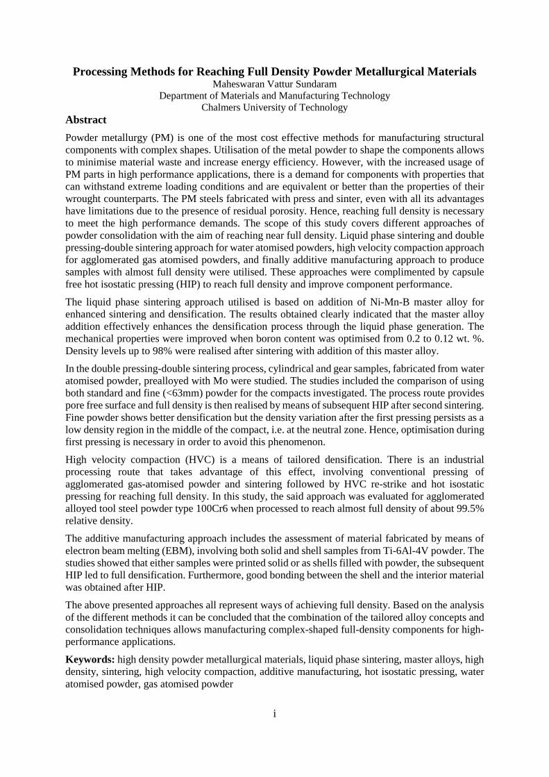
Abstract Powder metallurgy (PM) is one of the most cost effective methods for manufacturing structural components with complex shapes. Utilisation of the metal powder to shape the components allows to minimise material waste and increase energy efficiency. However, with the increased usage of PM parts in high performance applications, there is a demand for components with properties that can withstand extreme loading conditions and are equivalent or better than the properties of their wrought counterparts. The PM steels fabricated with press and sinter, even with all its advantages have limitations due to the presence of residual porosity. Hence, reaching full density is necessary to meet the high performance demands. The scope of this study covers different approaches of powder consolidation with the aim of reaching near full density. Liquid phase sintering and double pressing-double sintering approach for water atomised powders, high velocity compaction approach for agglomerated gas atomised powders, and finally additive manufacturing approach to produce samples with almost full density were utilised. These approaches were complimented by capsule free hot isostatic pressing (HIP) to reach full density and improve component performance.
The liquid phase sintering approach utilised is based on addition of Ni-Mn-B master alloy for enhanced sintering and densification. The results obtained clearly indicated that the master alloy addition effectively enhances the densification process through the liquid phase generation. The mechanical properties were improved when boron content was optimised from 0.2 to 0.12 wt. %. Density levels up to 98% were realised after sintering with addition of this master alloy.
In the double pressing-double sintering process, cylindrical and gear samples, fabricated from water atomised powder, prealloyed with Mo were studied. The studies included the comparison of using both standard and fine (<63mm) powder for the compacts investigated. The process route provides pore free surface and full density is then realised by means of subsequent HIP after second sintering. Fine powder shows better densification but the density variation after the first pressing persists as a low density region in the middle of the compact, i.e. at the neutral zone. Hence, optimisation during first pressing is necessary in order to avoid this phenomenon.
High velocity compaction (HVC) is a means of tailored densification. There is an industrial processing route that takes advantage of this effect, involving conventional pressing of agglomerated gas-atomised powder and sintering followed by HVC re-strike and hot isostatic pressing for reaching full density. In this study, the said approach was evaluated for agglomerated alloyed tool steel powder type 100Cr6 when processed to reach almost full density of about 99.5% relative density.
The additive manufacturing approach includes the assessment of material fabricated by means of electron beam melting (EBM), involving both solid and shell samples from Ti-6Al-4V powder. The studies showed that either samples were printed solid or as shells filled with powder, the subsequent HIP led to full densification. Furthermore, good bonding between the shell and the interior material was obtained after HIP.
The above presented approaches all represent ways of achieving full density. Based on the analysis of the different methods it can be concluded that the combination of the tailored alloy concepts and consolidation techniques allows manufacturing complex-shaped full-density components for high-performance applications.
Keywords: high density powder metallurgical materials, liquid phase sintering, master alloys, high density, sintering, high velocity compaction, additive manufacturing, hot isostatic pressing, water atomised powder, gas atomised powder

ii
iii
PREFACE This licentiate thesis is based on the work performed in the Department of Materials and Manufacturing technology at Chalmers University of Technology. The work has been carried out under the supervision of Professor Lars Nyborg and Associate Professor Eduard Hryha. This work has been performed within the framework of different projects supported by VINNOVA.
The thesis will introduce to the topic of powder metallurgy, with further review of the high density PM steels and its processes followed by chapters on various high density approaches and its summary is based on the appended papers as below
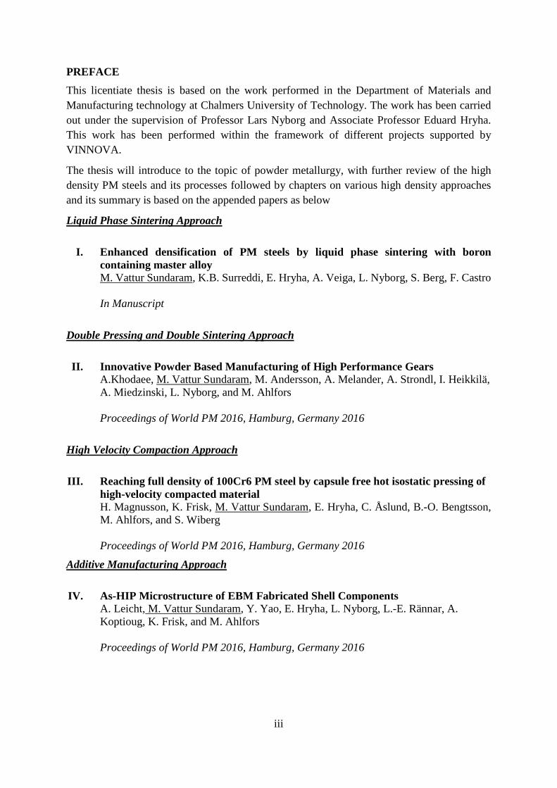
Liquid Phase Sintering Approach
I. Enhanced densification of PM steels by liquid phase sintering with boron containing master alloy M. Vattur Sundaram, K.B. Surreddi, E. Hryha, A. Veiga, L. Nyborg, S. Berg, F. Castro In Manuscript
Double Pressing and Double Sintering Approach II. Innovative Powder Based Manufacturing of High Performance Gears
A.Khodaee, M. Vattur Sundaram, M. Andersson, A. Melander, A. Strondl, I. Heikkilä, A. Miedzinski, L. Nyborg, and M. Ahlfors Proceedings of World PM 2016, Hamburg, Germany 2016
High Velocity Compaction Approach
III. Reaching full density of 100Cr6 PM steel by capsule free hot isostatic pressing of high-velocity compacted material H. Magnusson, K. Frisk, M. Vattur Sundaram, E. Hryha, C. Åslund, B.-O. Bengtsson, M. Ahlfors, and S. Wiberg Proceedings of World PM 2016, Hamburg, Germany 2016
Additive Manufacturing Approach IV. As-HIP Microstructure of EBM Fabricated Shell Components
A. Leicht, M. Vattur Sundaram, Y. Yao, E. Hryha, L. Nyborg, L.-E. Rännar, A. Koptioug, K. Frisk, and M. Ahlfors Proceedings of World PM 2016, Hamburg, Germany 2016
iv
Contribution to the appended Papers
I. The author planned and performed the experimental work, analysis of the results as well as wrote the paper with cooperation of the co-authors.
II. The author performed the characterisation of the material, as well as the analysis of the results and contributed to the writing of the paper.
III. The author took part in the planning and characterisation of the material and contributed to the writing of the paper.
IV. The author took part in planning in collaboration with the co-authors and also performed the material characterisation and as well as the analysis of the results along with the main author and contributed to the writing of the paper, along with the co-authors
Papers not appended in this thesis
I. Vacuum sintering studies on chromium alloyed PM steels M. Vattur Sundaram, S. Karamchedu, C. Gouhier, E. Hryha, L. Nyborg Proceedings of World PM 2016, Germany 2016
II. XPS Analysis of Oxide Transformation During Sintering of Chromium Alloyed PM Steels M. Vattur Sundaram, E. Hryha, and L. Nyborg, Powder Metallurgy Progress, vol. 14, no. 2, pp. 85–92, 2014.

v
CONTENTS 1 INTRODUCTION ..................................................................................................................... 1
Background ................................................................................................................. 1 Research Objectives .................................................................................................... 2
2 POWDER METALLURGY .................................................................................................... 3 Powder Production ..................................................................................................... 4 Alloying ....................................................................................................................... 5 Compaction ................................................................................................................. 6 Delubrication .............................................................................................................. 6 Sintering ..................................................................................................................... 7 Post-sintering Processes .............................................................................................. 7
3 PROPERTIES OF PM COMPONENTS ............................................................................. 8 Pore Free Density ........................................................................................................ 8 Influence of Density ..................................................................................................... 9 Effect of Porosity on the Properties ............................................................................. 9 Effect of Sintering Temperatures on Properties ........................................................ 10
4 HIGH DENSITY PROCESSES .......................................................................................... 12 Warm Compaction .................................................................................................... 12 Warm Die Compaction ............................................................................................. 12 Double Pressing and Double Sintering Approach ...................................................... 12 High Velocity Compaction Process ............................................................................ 13 Cold Isostatic Pressing .............................................................................................. 13 Powder Forging ......................................................................................................... 13 High Temperature Sintering ..................................................................................... 13 Liquid Phase Sintering .............................................................................................. 14 4.8.1 Boron in PM Steel ........................................................................................................... 15 Additive Manufacturing ............................................................................................ 16
Hot Isostatic Pressing ................................................................................................ 16
5 ANALYTICAL TECHNIQUES .......................................................................................... 18 Differential Scanning Calorimetry ............................................................................ 18 Dilatometry ............................................................................................................... 18 Density Measurements .............................................................................................. 18 Light Optical Microscopy .......................................................................................... 19 Scanning Electron Microscopy .................................................................................. 19 Hardness Testing....................................................................................................... 19
6 APPROACHES TO HIGH/FULL DENSITY .................................................................. 21
7 MATERIALS AND METHODS ......................................................................................... 23 Liquid Phase Sintering Approach ............................................................................. 23 Double Pressing and Double Sintering ...................................................................... 23 High Velocity Compaction ........................................................................................ 24 Additive Manufacturing ............................................................................................ 25
8 RESULTS AND SUMMARY OF PAPERS ..................................................................... 27 Liquid Phase Sintering - Paper I ............................................................................... 27 Double Pressing and Double Sintering Approach - Paper II ..................................... 29 8.2.1 Neutral Zone .................................................................................................................... 30 High Velocity Compaction – Paper III ...................................................................... 31

vi
Additive Manufacturing Approach - Paper IV .......................................................... 32
9 CONCLUSIONS ..................................................................................................................... 33
10 FUTURE WORK .................................................................................................................... 34 Liquid Phase Sintering Approach ............................................................................. 34 Cold Isostatic Pressing Approach .............................................................................. 34
11 ACKNOWLEDGEMENTS .................................................................................................. 35
12 REFERENCES ........................................................................................................................ 36

1
1 INTRODUCTION Background
Powder metallurgy (PM) as a manufacturing technology progressed rapidly during the last century, with structural PM steels constituting a major portion of the total PM parts produced globally [1], [2]. The uniqueness of PM is its ability to form complex shape components in a single pressing and single sintering step with high production volumes and low material waste. Application of PM is growing due to its cost competitiveness against other processes. Ferrous structural parts constitute almost 70% of the total PM parts produced globally [2]. When it comes to the PM steels, about 80% of the raw material for the powder production is coming from the recycled scrap. This makes it even more resource efficient and overall a sustainable manufacturing process [3], [4].
The typical densities for PM steels are between 7.0 to 7.2 g/cm3 which is ~ 90% of the theoretical density and remaining volume is generally occupied by pores. Pores are the limiting factors as they affect the final properties which in turn limits the range of applications. All the current applications of PM steels meet the part specific requirements well enough with low densities. Higher performance applications (e.g. gears, transmission parts and some engine components, etc.) demand more stringent property requirements. Considering components for dynamic loading conditions, high strength and fatigue properties should be close to the characteristic properties of wrought components. Therefore full or near full density is desirable to meet these high performance requirements and properties. Increasing the density is challenging [3], but in most cases increasing the alloying additions to improve the properties is an economically viable approach. Earlier studies have shown the dimensional instability associated with PM steel components when subjected to high loading conditions [5]. To avoid such behaviour or tendency, PM steels with full density could be a good solution.
Figure 1: Optical micrograph of polished PM steel with porosity (left) and full dense (right)
For PM manufacturing processes to remain competitive and have an advantage over other manufacturing processes such as casting, forging and machining, it is necessary to improve the process continuously in order to increase the current density levels and improve the properties, while maintain the advantage of PM as net-shaping or near-net-shaping technology. For high performance applications this can be done by number of ways as shown in Figure 1. Increasing the density to this stage involves pushing the limits of the processing equipment at the different stages of the PM process. Further such components can be densified by means of post sintering
Alloying +
Pressing +
Sintering +
Post Processing
2
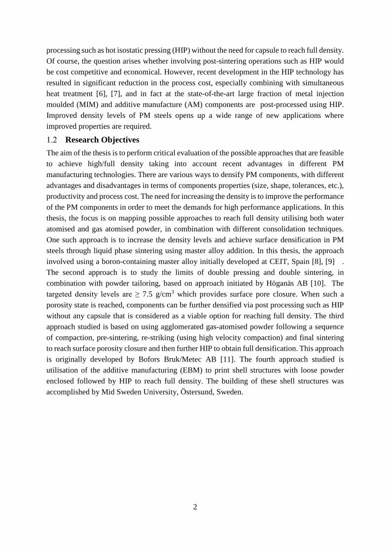
processing such as hot isostatic pressing (HIP) without the need for capsule to reach full density. Of course, the question arises whether involving post-sintering operations such as HIP would be cost competitive and economical. However, recent development in the HIP technology has resulted in significant reduction in the process cost, especially combining with simultaneous heat treatment [6], [7], and in fact at the state-of-the-art large fraction of metal injection moulded (MIM) and additive manufacture (AM) components are post-processed using HIP. Improved density levels of PM steels opens up a wide range of new applications where improved properties are required.
Research Objectives The aim of the thesis is to perform critical evaluation of the possible approaches that are feasible to achieve high/full density taking into account recent advantages in different PM manufacturing technologies. There are various ways to densify PM components, with different advantages and disadvantages in terms of components properties (size, shape, tolerances, etc.), productivity and process cost. The need for increasing the density is to improve the performance of the PM components in order to meet the demands for high performance applications. In this thesis, the focus is on mapping possible approaches to reach full density utilising both water atomised and gas atomised powder, in combination with different consolidation techniques. One such approach is to increase the density levels and achieve surface densification in PM steels through liquid phase sintering using master alloy addition. In this thesis, the approach involved using a boron-containing master alloy initially developed at CEIT, Spain [8], [9] . The second approach is to study the limits of double pressing and double sintering, in combination with powder tailoring, based on approach initiated by Höganäs AB [10]. The targeted density levels are ≥ 7.5 g/cm3 which provides surface pore closure. When such a porosity state is reached, components can be further densified via post processing such as HIP without any capsule that is considered as a viable option for reaching full density. The third approach studied is based on using agglomerated gas-atomised powder following a sequence of compaction, pre-sintering, re-striking (using high velocity compaction) and final sintering to reach surface porosity closure and then further HIP to obtain full densification. This approach is originally developed by Bofors Bruk/Metec AB [11]. The fourth approach studied is utilisation of the additive manufacturing (EBM) to print shell structures with loose powder enclosed followed by HIP to reach full density. The building of these shell structures was accomplished by Mid Sweden University, Östersund, Sweden.
3
2 POWDER METALLURGY
From a historical perspective, utilising metal powder for making goods, monuments and jewellery was adopted as early as 3000 BC by Egyptians. Inca’s used gold powder for making ornaments and in India reduced iron ore was used for making the iron pillar in Delhi which exists today as a standing example [3], [12]. The PM as an industrial process has grown rapidly within the last century. Earlier development was focused on tungsten filaments as it was not possible to process tungsten through other methods due to the high melting point. In case of PM steels, the earlier applications were for self-lubricating bearings and valves where the pores helped in retaining the lubricant.
The PM is the most energy and material efficient technology in comparison to e.g. casting, forging, machining, etc. In the case of PM, powder is consolidated into required shape and dimensions. This includes number of the following processes, as for example conventional uniaxial compaction, metal injection moulding (MIM), HIP, cold isostatic pressing (CIP) and AM [3] . The advantages of using PM are its ability to produce complex shaped components that are otherwise difficult or impossible to manufacture with precise dimensional control. The other advantages are the flexibility in alloy design and compositional control which is not possible by other methods. It is possible to produce materials with high melting points and difficult-to-machine materials. In some PM sectors, the move towards fine powder and advanced parts seems to be attractive.
The status of PM parts produced in the Europe as of 2014, revealed that ferrous PM accounts for 81% of the total parts produced in tonnage. The automotive segment continues to be the major consumer of the PM parts. Novel applications such as aerospace, medical, aero engine and land based gas turbines represent growing markets. The PM parts are also used in other areas such as agricultural machinery, heavy -mining and construction equipment, etc.
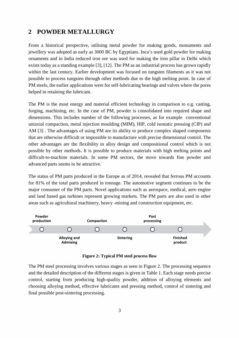
Figure 2: Typical PM steel process flow
The PM steel processing involves various stages as seen in Figure 2. The processing sequence and the detailed description of the different stages is given in Table 1. Each stage needs precise control, starting from producing high-quality powder, addition of alloying elements and choosing alloying method, effective lubricants and pressing method, control of sintering and final possible post-sintering processing.
Powder production
Alloying and Admixing
Compaction
Sintering
Postprocessing
Finished product
4
Table 1: Some of the processes involved within each PM processing steps
Processes Approach Powder
Production • Gas atomisation • Water atomisation
Powder alloying • Prealloying • Diffusion bonding • Admixing
Compaction
• Uniaxial compaction o Single pressing o Double pressing o Warm compaction o Warm die compaction
• Cold isostatic pressing • High velocity compaction
Sintering
• Low temperature sintering • High temperature sintering • Vacuum sintering • Liquid phase sintering
Post-sintering processing
• Heat treatments • Repressing/sizing • Secondary operations
Powder Production
Atomisation is the most common method for producing metal powder. In case of low alloyed steel powder, water atomisation is used. Gas atomisation is commonly used for manufacturing powders sensitive to oxidation such as e.g. high-alloyed steels, stainless steels, tool steels, titanium and its alloys, etc.
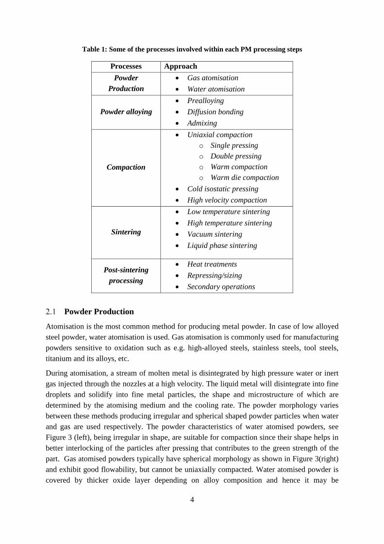
During atomisation, a stream of molten metal is disintegrated by high pressure water or inert gas injected through the nozzles at a high velocity. The liquid metal will disintegrate into fine droplets and solidify into fine metal particles, the shape and microstructure of which are determined by the atomising medium and the cooling rate. The powder morphology varies between these methods producing irregular and spherical shaped powder particles when water and gas are used respectively. The powder characteristics of water atomised powders, see Figure 3 (left), being irregular in shape, are suitable for compaction since their shape helps in better interlocking of the particles after pressing that contributes to the green strength of the part. Gas atomised powders typically have spherical morphology as shown in Figure 3(right) and exhibit good flowability, but cannot be uniaxially compacted. Water atomised powder is covered by thicker oxide layer depending on alloy composition and hence it may be
5
subsequently annealed in reducing atmosphere to remove oxides and to settle good compressibility. After the annealing, the powder surface is covered by a thin oxide layer of the base metal with the presence of the low amount of oxide particles. The thin oxide layer is basically a result of the handling the powder in air after the annealing, while the oxide particles may be remains from the annealing. Depending on alloying elements present, the surface features will be enriched accordingly. In case of gas-atomised powder, additional annealing procedure is not required as powder possesses high purity after atomisation. Figure 3 shows irregular and spherical morphology of typical water and gas atomised metal particles.
Figure 3: SEM micrographs showing typical powder morphology of water (left, courtesy of Dr.
Seshendra Karamchedu) and gas atomised powder (right, courtesy of Alexander Leicht).
Alloying
(a) (b) (c) (d)
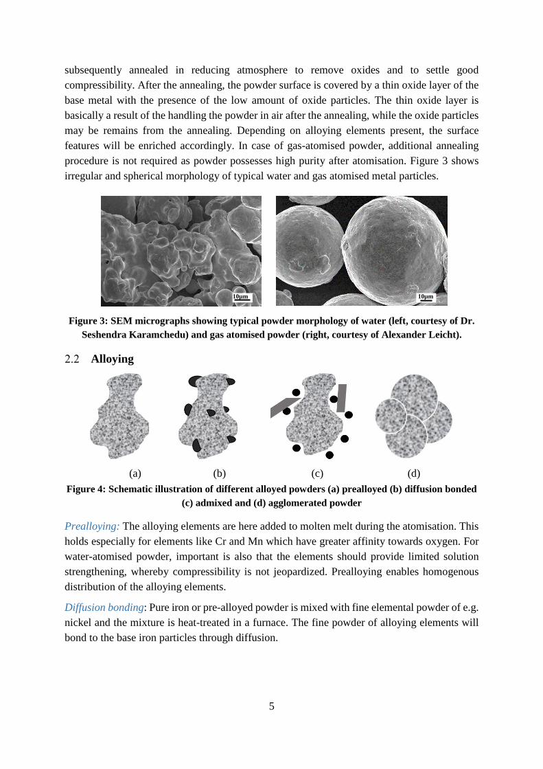
Figure 4: Schematic illustration of different alloyed powders (a) prealloyed (b) diffusion bonded (c) admixed and (d) agglomerated powder
Prealloying: The alloying elements are here added to molten melt during the atomisation. This holds especially for elements like Cr and Mn which have greater affinity towards oxygen. For water-atomised powder, important is also that the elements should provide limited solution strengthening, whereby compressibility is not jeopardized. Prealloying enables homogenous distribution of the alloying elements.
Diffusion bonding: Pure iron or pre-alloyed powder is mixed with fine elemental powder of e.g. nickel and the mixture is heat-treated in a furnace. The fine powder of alloying elements will bond to the base iron particles through diffusion.
10µm 10µm

6
Admixing: This is a flexible method of producing powder mixes, by mixing iron/steel powder with the powder of required alloying elements. Graphite, additives and lubricants are mixed during this process.
Powder Agglomeration: Gas atomised powder is agglomerated using a binder to form agglomerates that macroscopically looks like irregular shaped particles, providing consolidation opportunity and green strength after pressing. This is the basis for the Scanpac process by Metal Value/Bofors Bruk (formerly Metec Powder Products) [13].
Compaction
Uniaxial compaction is the most common method of densification in PM steels. Water atomised powder admixed with lubricant and graphite is filled in the die cavity and pressed by the axial movement of the punches [14]. The compaction pressure is typically between 400 to 1000 MPa. During the powder pressing, the metal particles will rearrange with the pressure exerted by the punches and interlocking between them occurs due to their irregular shape. Sometimes even cold welding of the particles can take place at high pressures. This gives the compact sufficient green strength for further handling. There will be a density gradient after pressing due to the difference in pressure distribution because of the moving punches and solid die. This density gradient is especially created in the surface region along the compaction direction owing to the frictional resistance at die wall, while it is much less pronounced inside the compact. The compaction presses are either mechanical or hydraulic with multilevel punch movements. For the multilevel components (e.g. synchroniser hubs, oil pump gears, etc.), in order to have the uniform densification and to avoid variation in density among different sections, the punches moves relative to one another with the help of platens according to the density requirements of different sections in the component [14]. The component size is limited by the weight maximum and the aspect ratio (height to diameter ratio), since the ejection forces will be too high with the increased height. The final properties of the PM component obtained heavily depends on this stage of the process. To overcome these issues and have high density after pressing there are other possible ways [15]–[17] that will be discussed in the following chapter 4.
Delubrication
The additives, such as lubricants or binders, admixed before the compaction step have to be removed completely before sintering. In case of gaseous sintering process, delubrication is carried out in the zone prior to the sintering zone in a continuous sintering furnace. The typical temperature recommended for the delubrication of Cr-alloyed PM steels is 450 °C for 30 minutes in a dry inert (e.g. nitrogen) atmosphere [18]. At this temperature, the powder characteristics remain unchanged after delubrication. The removal of the lubricant occurs in two stages, starting with the melting and then decomposition [18]. The various parameters affecting delubrication are initial density, heating rates, sample geometry, gas flow rates, temperature, and atmosphere composition. Improper control of these parameters can adversely affect the final properties of the components after subsequent sintering.
7
Sintering
Sintering imparts necessary strength to the component by creating bonding between the metal particles. Sintering is usually performed below the melting point at roughly 75-80% of the melting temperature. Through the mass transport between the adjoining metal particles, the inter-particle necks are developed. Surface diffusion is dominant in the case of the solid state sintering of PM steels. The degree of sintering is determined by the number and strength of the established sinter necks. Formation and growth of inter-particle necks are enabled by early and efficient reduction of the surface oxides covering the powder [19], [20]. Sintering in reducing atmospheres removes the surface oxides. Admixed graphite also plays an extremely vital part during deoxidation by reducing the oxides through direct and indirect carbothermal reduction mechanisms.
In PM steels, endo gas is the most commonly used sintering atmosphere. When it comes to Cr-alloyed PM steels, N2-10%H2 is used as a processing atmosphere for reducing oxides. During cooling endo gases provide carbon restoration but not with Cr-alloyed PM steels. Hence, carbon control during sintering is vital in order to reach the required properties [21]. Studies on lean sintering atmospheres containing carbon monoxide have shown that the CO acts as both reducing-oxidising and carburising–decarburising agent [18]. This implies that proper control of the atmosphere during sintering is extremely critical for robust PM steel processing and also for tailoring the sintered properties. Apart from solid state sintering, which mainly contributes to the strengthening of PM steel, liquid phase sintering can be applied to improve densification. This can be applied to improve densification during sintering without changing demand on the compacting stage and hence minimizing demands on new equipment solutions for compaction. Liquid phase sintering is covered in chapter 4.
Post-sintering Processes Following the sintering, the secondary operations involved depend very much on the part specific requirements that it has to fulfil. There are number of operations such as sizing or repressing to increase the density and retain the final dimensional tolerances. Heat treatments such as steam treatment, case hardening (carburising, nitriding, induction hardening, etc.) are perfomed to obtain the desired microstructure and these processes are usually followed by a tempering operation. Continuous sintering process offers another advantage of rapid cooling in the cooling zone after sintering with a cooling rate of ~ 2.5 to 5 °C/s, which allows component hardening. This is called sinter hardening process as it combines both sintering and hardening in a single process [22]. As mentioned above, all these hardening processes can be “avoided” by sinter hardening. Tempering at 200 or 300 °C is performed to improve the toughness of the components, involving relieving the stresses incurred during the hardening and also the initial tempering of the martensitic microstructure. Dimensional instability associated with the PM steel parts in applications can be avoided by optimised tempering [5]. Other processes such as oil impregnation, machining, grinding, honing and lapping, etc., depending on the requirements, can be applied as well.
8
3 PROPERTIES OF PM COMPONENTS Pore Free Density
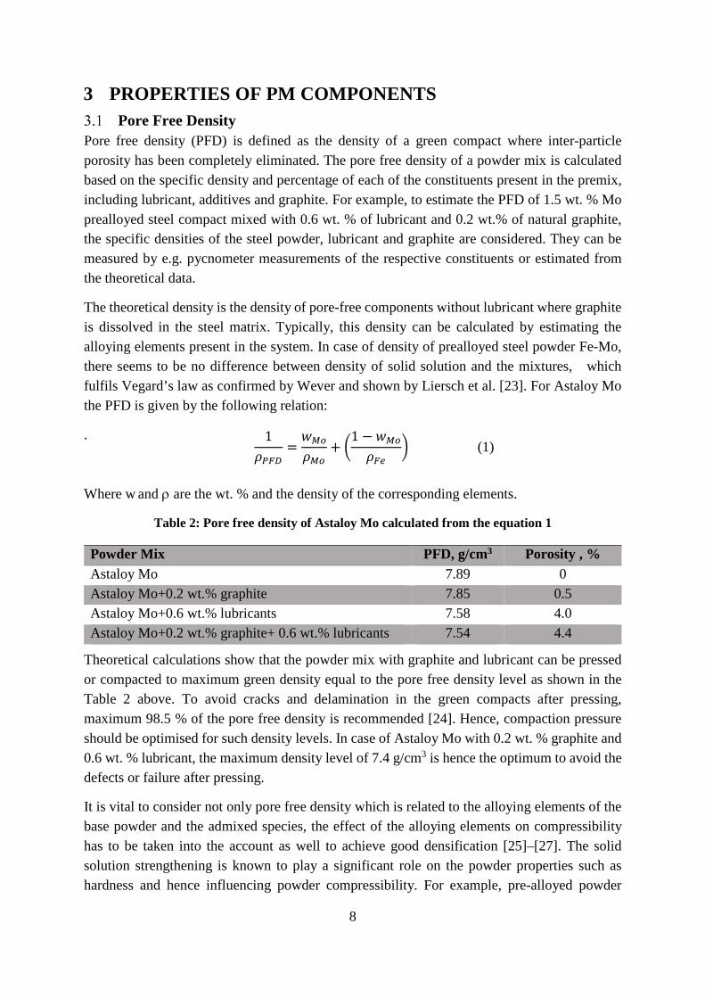
Pore free density (PFD) is defined as the density of a green compact where inter-particle porosity has been completely eliminated. The pore free density of a powder mix is calculated based on the specific density and percentage of each of the constituents present in the premix, including lubricant, additives and graphite. For example, to estimate the PFD of 1.5 wt. % Mo prealloyed steel compact mixed with 0.6 wt. % of lubricant and 0.2 wt.% of natural graphite, the specific densities of the steel powder, lubricant and graphite are considered. They can be measured by e.g. pycnometer measurements of the respective constituents or estimated from the theoretical data.
The theoretical density is the density of pore-free components without lubricant where graphite is dissolved in the steel matrix. Typically, this density can be calculated by estimating the alloying elements present in the system. In case of density of prealloyed steel powder Fe-Mo, there seems to be no difference between density of solid solution and the mixtures, which fulfils Vegard’s law as confirmed by Wever and shown by Liersch et al. [23]. For Astaloy Mo the PFD is given by the following relation:
.
Where w and ρ are the wt. % and the density of the corresponding elements.
Table 2: Pore free density of Astaloy Mo calculated from the equation 1
Powder Mix PFD, g/cm3 Porosity , % Astaloy Mo 7.89 0 Astaloy Mo+0.2 wt.% graphite 7.85 0.5 Astaloy Mo+0.6 wt.% lubricants 7.58 4.0 Astaloy Mo+0.2 wt.% graphite+ 0.6 wt.% lubricants 7.54 4.4
Theoretical calculations show that the powder mix with graphite and lubricant can be pressed or compacted to maximum green density equal to the pore free density level as shown in the Table 2 above. To avoid cracks and delamination in the green compacts after pressing, maximum 98.5 % of the pore free density is recommended [24]. Hence, compaction pressure should be optimised for such density levels. In case of Astaloy Mo with 0.2 wt. % graphite and 0.6 wt. % lubricant, the maximum density level of 7.4 g/cm3 is hence the optimum to avoid the defects or failure after pressing.
It is vital to consider not only pore free density which is related to the alloying elements of the base powder and the admixed species, the effect of the alloying elements on compressibility has to be taken into the account as well to achieve good densification [25]–[27]. The solid solution strengthening is known to play a significant role on the powder properties such as hardness and hence influencing powder compressibility. For example, pre-alloyed powder
1
𝜌𝜌𝑃𝑃𝑃𝑃𝑃𝑃=𝑤𝑤𝑀𝑀𝑀𝑀
𝜌𝜌𝑀𝑀𝑀𝑀+ �
1 − 𝑤𝑤𝑀𝑀𝑀𝑀
𝜌𝜌𝑃𝑃𝐹𝐹� (1)

9
depending on effect of specific alloying element require higher compaction pressures than the diffusion bonded or blended powder to reach similar density levels [9]. This is because of solution hardening of the ferrous particles (hardening of ferrite) by alloying elements.
Influence of Density Numerous studies have shown how the density influences the properties of PM steel and is a limiting factor for applications. Based on the summary and review of all the previous studies, Beiss et al. [28] have given the following general relation to estimate the PM steel properties:
𝑃𝑃 = 𝑃𝑃0�𝜌𝜌𝜌𝜌0� �
𝑚𝑚 (2)
where, 𝑃𝑃 is the property of the PM material, 𝑃𝑃0 is the property of the pore free material, 𝜌𝜌 is the density of the PM material and 𝜌𝜌0 is the theoretical density of pore free state. The value of 𝑚𝑚 varies between 2 to 3 depending on the type of powder and sintering conditions.
Figure 5: Mechanical properties vs the relative density of PM steels with different processes
redrawn from [29]
Figure 5 summarises the effect of density on the mechanical properties in dependence on different processes, showing increase in all cases with increasing relative density. Numerous studies [30]–[32] have shown in particular the effect of density on the strength of the PM steel. The way to achieve specific density level, i.e. the consolidation technique applied, appears not be crucial, but rather the resulting density itself [33].
Effect of Porosity on the Properties
When it comes to the applications such as gears, fatigue properties play a crucial role. Even the presence of small amount of inclusions tends to be detrimental for the performance of the normal gear wheels. Hence, the presence of the pores in the PM steels will have an unprecedented effect on the material properties as they result in stress concentration regions. Still, the major issue with PM steel is of course the pore characteristics. In addition to the porosity level, the mechanical properties are affected by the amount of pores, their size

10
distribution and pore morphology [34]. Depending on the kind of pores there are differences in their impact. Open or interconnected pores have more significant effect on mechanical properties rather than isolated and closed pores. The interconnected pores are dominant when the porosity level exceeds > 5%. Fatigue cracks initiate and grow through such pores and pore clusters [34]. The higher the sintered density or smaller the pores size, the lower effect on the properties can be expected with respect to fatigue properties.
Considering the sintering to higher sintered density, there is a concern when reaching low porosity of less than 5 % when interconnected porosity practically ceases. This also means that gas transport inside the sintered part is limited and hence there is a risk that surface oxides are not reduced. At high temperatures, the reduction is governed by the carbothermal reactions set up via the initial presence of admixed graphite. To enable, the effective reduction, it is hence important that the necessary microclimate conditions are created early during the sintering. . Sintering in vacuum at high temperatures has been shown to be an option to consider for large components with high densities[35], [36].
Another interesting aspect of the PM gears is the ability to trap the lubricants owing to characteristic pores that provides improved frictional and wear properties [37]. Li et al. [38] have shown how the pore size is important in case of mating gears. With the presence of larger pores in PM gear surfaces, damage due to scuffing and peeling occurred on the mating surfaces. Hence, it was recommended to have smaller pore size when using PM gears for best performance. When it comes to corrosion resistance, presence of open pores at the surface tends to be a concern as well. The post-sintering heat treatment of PM parts like carburizing or carbo-nitriding when carried out in the presence of open or interconnected pores resulting in deeper penetration of active gas forming inconsistence case depth [39]. To improve the fatigue properties of PM gears, considering tooth root failure, selective densification of gear sections and surfaces such as tooth and the flank have been employed. It was shown [40] how gear rolling or surface rolling can be used to increase the load bearing capacity leading to surface densification of the PM gears that in turn improves the fatigue properties almost equal to the wrought material .
Effect of Sintering Temperatures on Properties
Haynes et al. [41] have shown how the property of the pure iron powder varies for sintering at low and high temperatures. Their results indicate that compacts made of pure iron powder for fixed density exhibit better mechanical properties either with increasing sintering time or increasing temperature. This is supposed to be a result of the reduced stress concentration owing to the rounding of pores. The strength of the PM material is related to the load bearing area that in turn is typically governed by the extent and characteristics of inter-particle necks. A model developed for predicting strength evolution considering the inter-particle neck size [42] showed very good correlation with actual mechanical properties. The inter-particle necks grow during sintering. Stronger necks denotes better mechanical properties [43]. The higher the density is, the better the contact is between the metal particles and the lower is also the porosity. To improve the load carrying capacity in PM steels, the relative density levels of above 95% are

11
required [28]. As this is the limit of density at which the open pores change to closed ones, it is essential to determine and also to optimise the pressing operation [44].
Figure 6: Fracture surface of the typical PM steel showing well-developed necks, inter- and
trans-particle dimple ductile fracture
It is also essential during the initial stages of sintering to have the interconnected pores open to the surface. Open pores are necessary for the efficient removal of the lubricants and also in order to enable escape of gaseous products (like water vapour) at early reduction of iron oxide, important for the formation of inter-particle necks. The neck formation starts with the inter-particle contacts and grows with increase in temperature, forming a continuous network. Through diffusion, strong inter-particle necks are formed and this is a necessity for good mechanical properties. This kind of characteristics can be assessed by means of the analysis of the fracture surfaces of tested sintered specimens. Figure 6 illustrates the fracture surface with the presence of the interparticle and transparticle failure regions with completely reduced powder surfaces and well developed necks as an example of well sintered material.
12
4 HIGH DENSITY PROCESSES For the continuous progress of PM industry, the trend towards reaching higher relative density levels should be emphasised. There has been an increasing trend in the usage of high density PM steels over the last decades [45]. Through improvements and innovation in alloy design, machine development (compaction techniques) and liquid phase sintering, a significant increase in the density and overall material properties has been demonstrated. To sustain the future development of PM and competitiveness with the other manufacturing processes, reaching full or near-full density is a key factor. There are various processes within the PM field that can be used alone or in combination to achieve increased density levels [24], [32]. These processes can be classified into compaction-based, sintering-based and hybrid approaches and include methods as listed below.
• Warm compaction • Warm die compaction • Double pressing and double sintering (DPDS) • High velocity compaction (HVC) • Cold Isostatic pressing (CIP) • Powder forging (PF) • High temperature sintering (HTS) • Liquid phase sintering (LPS) • Additive manufacturing (AM) • Hot isostatic pressing (HIP)
Warm Compaction
In this process, both die and powder are preheated to a temperature of 130-140°C at which compaction is performed. Here, densities of up to 7.3 g/cm3 for ferrous material can be achieved.
Warm Die Compaction
Unlike warm compaction, only the die is now heated and the powder remains at room temperature. This procedure allows for increase in productivity and decrease in process costs. However, lower density levels are achieved in comparison with the warm compaction, see Figure 5.
Double Pressing and Double Sintering Approach
In this process, component after first compaction is pre-sintered. By doing so, the lubricants are removed and material is annealed, which helps during the second pressing stage. Then it is again compacted and sintered at high temperature to obtain higher density. The pores remaining after the lubricant removal will be eliminated to some extent which contributes to the increase in density of about ~ 3 to 4%. This approach can be considered as a pressure-based densification

13
process. Sintering at high temperature is performed after second pressing to attain high density and also the distortions are avoided, which retain the component tolerances and dimensions.
High Velocity Compaction Process
Powder densification is achieved by intense shock waves generated from the high velocity striking of the die. This high energy can be utilised to impact the samples once or twice based on the machine capacity. It is up to 1000 times faster than the conventional pressing. Components produced are characterised by the uniform density with lower ejection force and spring back [46] but only simple geometries can be compacted. The amount of lubricant can be reduced or even avoided in some cases with this process [47].
Cold Isostatic Pressing
In this process, pressure is applied uniformly at room temperature through pressurising medium like liquid or air. The process can be either the wet bag process or dry bag process, depending on how the moulds are used. In the wet bag process, a flexible rubber mould is filled with powder which is then sealed and evacuated. The mould with powder inside is further placed directly in the cold isostatic pressing (CIP) chamber and exposed to the pressurising liquid. In the dry bag process, the flexible mould is fixed within the chamber and is filled with powder before each compaction cycle. The CIP is highly advantageous with regard to the component size, cheaper mould price (in comparison with HIP) and the ability to achieve homogeneous density distribution without the need for lubricants. These features make CIP an attractive consolidation process [48]. Due to the isostatic pressing, the density variation inside the component being small reduces the distortions during sintering [3], [12].
Powder Forging
In this process the compact either in green, pre-sintered or sintered state is hot forged into a final fully-dense component [12]. Almost all the automotive connecting rods, produced nowadays, are processed through powder forging.
High Temperature Sintering
Sintering at around 1120 °C is a standard industrial practice for majority of PM components, the reasons being that industrial belt furnaces are limited in use to around such a temperature, while there is also a concern not to apply too high temperature to maintain proper tolerance control of sintered parts. Sintering at higher temperature is, however, beneficial for more efficient oxide reduction since the equilibrium for oxide reduction is shifted with increasing temperature. This fact is of particular importance in case of PM steels containing alloying elements like Cr, Mn and Si all prone to form stable oxides. At higher temperatures, lattice diffusion becomes also significantly improved and this fact plays a major role in alloy homogenisation, which is important in particular for the case of admixed and diffusion alloyed PM steels. Another important effect of the high-temperature sintering is the rounding of the pores and strengthening of the inter-particle necks owing to e.g. improved oxide reduction, which results in a significant improvement in the strength, especially fatigue properties of PM
14
components [44]. The drawback with high temperature sintering may be that there is some more marginal shrinkage during sintering and hence dimensional control could be worse.
Liquid Phase Sintering
Liquid Phase sintered components account for ~70% of all the sintered goods which includes low alloyed steels, tool steels and especially hard metals [49]. Liquid phase sintering (LPS) is a well-known method to achieve densification through addition of low melting alloys or elemental powder that melts below the sintering temperature. The densification is hence assisted by liquid phase formation. The LPS is employed mainly in the case of high speed steels, tool steels and hard metal, where the necessity for LPS is realised to its full potential. With respect to low alloyed ferrous PM steel components, LPS is not a dominant process. For ferrous PM, the liquid phase formers are added either in the form of elemental mix or as a master alloy.
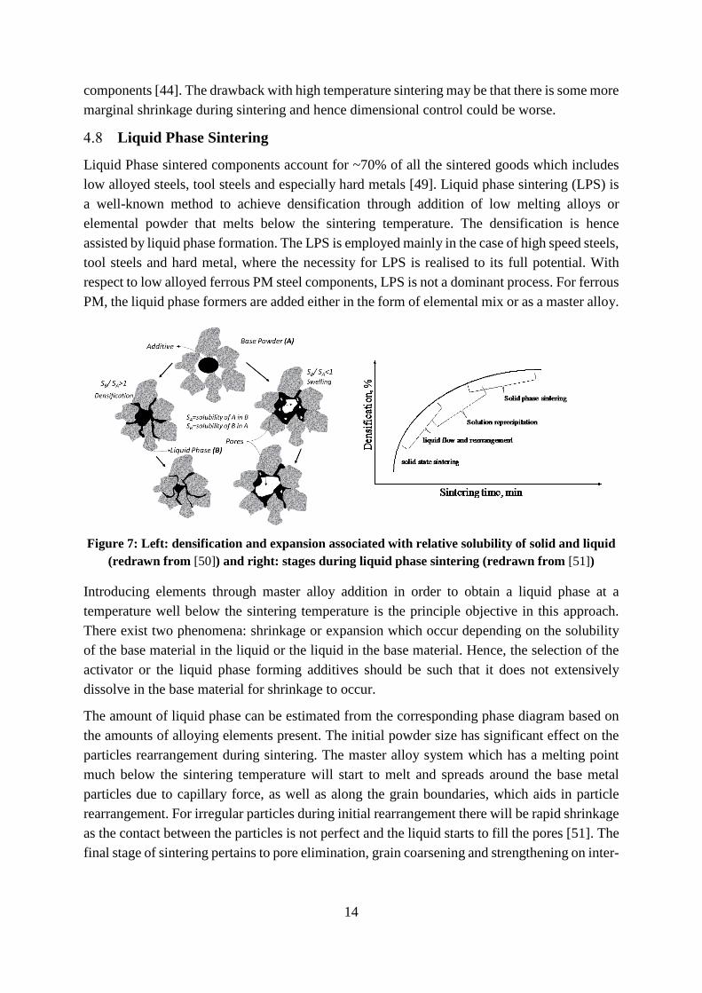
Figure 7: Left: densification and expansion associated with relative solubility of solid and liquid (redrawn from [50]) and right: stages during liquid phase sintering (redrawn from [51])
Introducing elements through master alloy addition in order to obtain a liquid phase at a temperature well below the sintering temperature is the principle objective in this approach. There exist two phenomena: shrinkage or expansion which occur depending on the solubility of the base material in the liquid or the liquid in the base material. Hence, the selection of the activator or the liquid phase forming additives should be such that it does not extensively dissolve in the base material for shrinkage to occur.
The amount of liquid phase can be estimated from the corresponding phase diagram based on the amounts of alloying elements present. The initial powder size has significant effect on the particles rearrangement during sintering. The master alloy system which has a melting point much below the sintering temperature will start to melt and spreads around the base metal particles due to capillary force, as well as along the grain boundaries, which aids in particle rearrangement. For irregular particles during initial rearrangement there will be rapid shrinkage as the contact between the particles is not perfect and the liquid starts to fill the pores [51]. The final stage of sintering pertains to pore elimination, grain coarsening and strengthening on inter-

15
particle necks. One critical consideration during sintering is the preservation of the dimensional stability of the component. For this, tailored master alloy approach is well suited [52]–[54].
Master alloy additions to PM steels were studied by Zapf et al. [55] in the beginning of 70’s using Mn-Cr-Mo additions and they found that this gave better mechanical strength considering the very least addition of each alloying element. Master alloy in ferrous PM steel has been widely studied before using different alloying additions, especially based on phosphorus and boron compounds, which form eutectic at low temperatures. Boron addition is of special interest and is addressed in this work.
4.8.1 Boron in PM Steel In PM steels, boron is an attractive alloying element and is added in large quantity as compared to the wrought steels. Here it acts as sintering enhancer and enables the formation of liquid phase and promotes densification [16]. Based on primary investigation by Klein et al. [56] relative density levels of 99.7% were reached for carbonyl powder sintered with 0.97 wt.% boron. According to Madan et al. [57] boron is a good sintering activator for iron, based on the electronic configuration, thermodynamic phase stability criteria and grain boundary cohesion criteria.
Boron addition enhances sintering by formation of liquid phase due to the eutectic reaction Fe(γ) +Fe2B L at ~1175 °C. Due to the unipolar solubility, iron will dissolve in the liquid and not the other way around as the B has extremely low solubility in Fe. More liquid will be generated when iron dissolves in the liquid that then will have persistent character with an excellent wettability with the dihedral angle being less than 10° [58]. Due to thereby strong capillary action, the liquid will penetrate the particle boundaries and inter-particle regions with ease and finally impregnate into the grain boundaries. This causes shrinkage overall by primary and secondary rearrangement of the metal particles as illustrated in Figure 7. The liquid phase will act as a short circuit path for diffusion of iron and as a result densification will occur eventually.
Studies by German et al. and by Madan et al. [57], [59] have shown that with increasing boron content the density increases, which improves the strength and hardness but lowers the ductility. Selecká et al. [60] have shown that boron addition of up to 0.2 wt. % results in no significant increase in the density for Fe and Fe-Mo materials when sintered at 1200°C for 60 min. There is a significant increase in the density only when boron is added beyond the level of 0.2 wt. %. This is related to the amount of liquid phase formed that helps the densification. The boron ensures that there will be adequate liquid generation, when added in quantities corresponding to total level beyond > 0.2 wt. %. This will also result in an increase in hardness due to the formation of continuous boride network along the grain boundaries, which is extremely brittle. Infiltration of iron-carbon compacts with different materials based on the Fe-B system (ferroboron) have been studied for making composites with very high hardness [61].
Boron is added either as elemental powder, ferroboron or master alloy mix in range of 0.01 to 1.2 wt. % of boron. Appropriate alloying method should be chosen to obtain the maximum

16
utilisation of its liquid phase sintering effect. Though the boron addition increases the density, the consequent embrittlement effect is still an issue. Even though the Fe-B alloy system has been known for years, numerous studies have shown that the problem still persists [58]. Adding boron as a master alloy addition has been studied extensively for ferrous steel and stainless steel 316L [8], [52], [54], [62], [63] and the reports have shown densification in combination with high ductility. This is of significant interest in our case to review and explore the appropriate master alloy containing boron.
Additive Manufacturing
Additive manufacturing (AM) involves adding the material layer by layer required for building a component. The AM offers flexibility in manufacturing, as components with complicated features and shape can be manufactured. It contributes to lower material waste. Powder bed process with utilisation of the focused energy source as electron or laser beam is commonly used for layer by layer fabrication of structural components to its final dimensions. Powder is locally melted using electron beam or laser beam when it moves along and fuses the powder after every layer of spreading.
Figure 8: Interdependence of additive manufacturing
Electron Beam Melting (EBM) involves preheating the powder chamber to ~600 to 700 °C and pre-sintering powder layer in vacuum before the local melting process, whereas in laser sintering (LS, also known as Direct Metal Laser Sintering (DMLS) or Selective Laser Melting (SLM)) is performed in an inert atmosphere (N2 or Ar) inside the build chamber without any preheating. Both EBM and LS process itself can provide up to full densities of > 99.5% with optimised process parameters. Factors such as powder properties, powder purity, process parameters (laser/electron beam power, scan speed, layer thickness, hatch spacing, building direction, component design, etc.) will certainly effect the final component properties. Figure 8 shows the interdependence of material, design and process that are interlinked for fabricating the defect free and fully dense AM component.
Hot Isostatic Pressing
Hot isostatic pressing (HIP) involves simultaneous application of pressure and temperature onto a metallic container encapsulating the powder or components containing porosity in order to reach full densification. Figure 9 shows the cross section of the typical hot isostatic press. This process is used to eliminate pores, defects and also for heat treatment of cast parts, powder

17
consolidation, densifying ceramic and metal parts, material joining, infiltration and densification of powder-based components [64]. The consolidation in HIP is usually done by having powder filled into a capsule of the required dimensions made of similar material. The capsule is further evacuated, sealed and placed in the HIP. Upon HIP, the powder is densified into a single part with the help of high pressure and temperatures. The densification is governed by yield, creep and final diffusion process. The main advantage of the HIP is the very large components with high length to diameter ratio that can be HIP-processed, otherwise difficult/impossible to realise by means other alternative techniques as e.g. die pressing [64].
Figure 9: Cross section of the Hot Isostatic Press [courtesy: Quintus Technologies AB]
The sequence of stages involved before the HIP consists of preparation of the capsule, filling with powder, welding, evacuation and sealing. After HIP process, the capsule have to be removed. Hence, this process is more time consuming and not economical for mass production. However, it is also a very widely applied technology for securing full density in the case of components produced by MIM and AM. For parts created with these methods, there is no need for the capsule as they are fabricated before HIP to the near-full density and closed porosity. Similar approach connected to closing surface porosity by means of different methods and further HIP is elaborated in this thesis study the conventional pressed and sintered PM components. The recent development of the HIP furnace systems with the combination of rapid cooling and quenching not only reduces the HIP processing time but also means that the heat-treatment and hardening processes can integrated in the HIP run [7].

18
5 ANALYTICAL TECHNIQUES Differential Scanning Calorimetry
Differential scanning calorimetry (DSC) is a thermo-analytical technique which measures heat flow between the sample and reference material during controlled temperature profile. Alumina crucibles with lids were used in this study; one for the samples and one as an empty crucible to record the difference in the heat flow. The energy absorbed or released associated with specific phase change as e.g. crystallisation, melting, phase transformations, etc., was measured. It is used for determining the phase transformation temperatures as well as specific heat capacity of the material.
In this study, simultaneous thermal analyser STA 449 F1 Jupiter® was used with DSC sensor which allows both DSC and TG measurements in one run. All the trails were performed using high purity Ar gas atmosphere with heating and cooling rate of 10 K/min. A correction run was performed before starting the actual measurements with the same temperature profile, using same crucible material and atmosphere.
Dilatometry
The thermal expansion or shrinkage associated with the phase transformations can be determined using the dilatometer by accurately measuring the dimensional change during controlled temperature profile. As the sintered properties are affected by the heating and cooling rate, it is essential to have a controlled process to simulate the actual conditions here. DIL402C horizontal pushrod dilatometer from Netzsch equipped with W-Re thermocouple that can be used for reducing and inert atmospheres was applied in this study. Dilatometer is equipped with vacuum-tight SiC furnace and is connected to the rotary and turbo pump that allows to perform sintering in vacuum up to 10-4 mbar. It is possible to have a very good atmosphere control and flexibility to change the atmosphere during the process with the help of mass flow controller.
The sample is placed in the alumina sample holder and the push rod is pushed against the sample with a minimum force of 25 cN. The push rod is connected to the transducer that converts the linear displacement into electrical signals with a resolution of up to 0.125 nm or 1.25 nm, depending on the measurement range. Before starting the experiment, the dilatometer is evacuated and further flushed three times using high purity Ar gas and the program is set to begin with the appropriate atmosphere.
Density Measurements
Density measurements were done according to the Archimedes principle (ISO 3369). This was done by measuring the weight of the sample in air first and measuring the weight of sample in the water using a special set up. The density of the sample is calculated according to:
Density, 𝜌𝜌 = 𝑚𝑚𝑎𝑎×𝜌𝜌𝑤𝑤𝑚𝑚𝑎𝑎−𝑚𝑚𝑤𝑤
(in g/cm3) (3)
19
where, 𝑚𝑚𝑎𝑎 and 𝑚𝑚𝑤𝑤 are the masses of the sample in air and water in gram and 𝜌𝜌𝑤𝑤 is the density of water (1 g/cm3). The samples are impregnated with paraffin wax to seal the pores in case of open pores.
Light Optical Microscopy
Light optical microscope is a basic yet powerful tool in the field of materials science. As the light source illuminates the surface of a sample, the reflected light is collected through the lenses forming the image. This image can be captured by the digital camera for further analysis. The image resolution is limited by the wavelength of the light and numerical aperture of the objective. In this work Leitz DMRX microscope equipped with Zeiss digital camera and AxioVision software for analysis was used. All the metallographic samples were polished and etched to reveal the microstructure under the light optical microscope.
Scanning Electron Microscopy
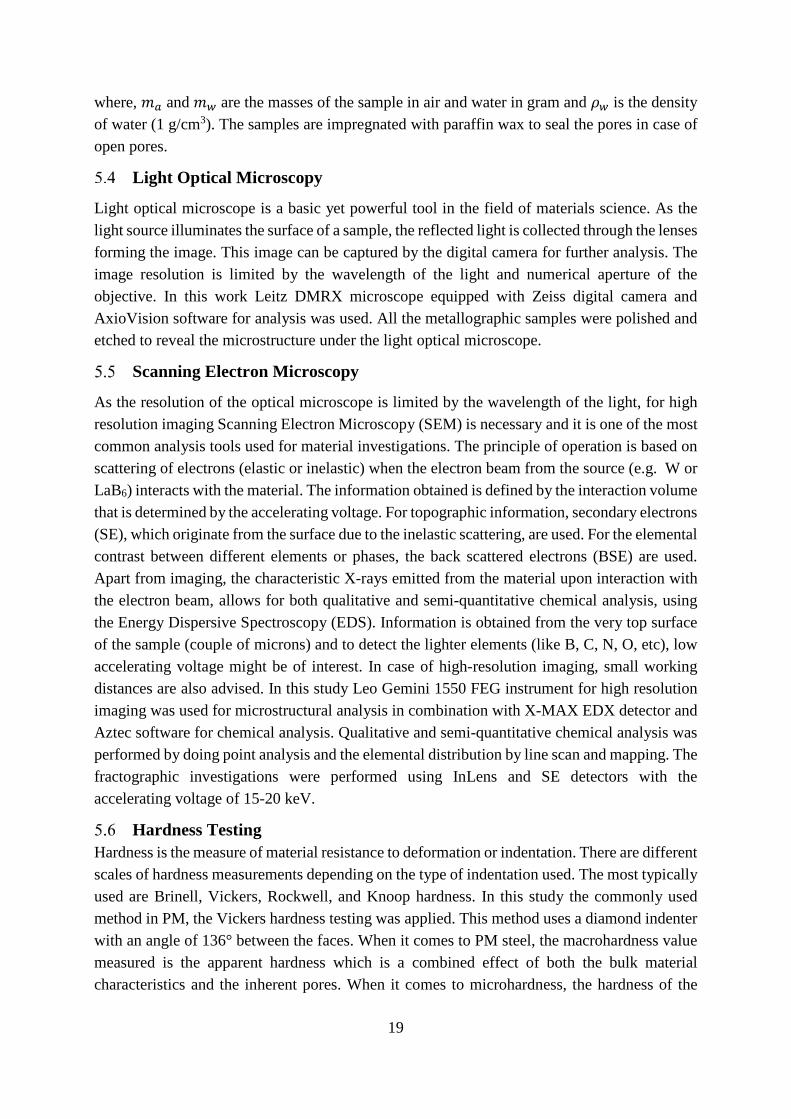
As the resolution of the optical microscope is limited by the wavelength of the light, for high resolution imaging Scanning Electron Microscopy (SEM) is necessary and it is one of the most common analysis tools used for material investigations. The principle of operation is based on scattering of electrons (elastic or inelastic) when the electron beam from the source (e.g. W or LaB6) interacts with the material. The information obtained is defined by the interaction volume that is determined by the accelerating voltage. For topographic information, secondary electrons (SE), which originate from the surface due to the inelastic scattering, are used. For the elemental contrast between different elements or phases, the back scattered electrons (BSE) are used. Apart from imaging, the characteristic X-rays emitted from the material upon interaction with the electron beam, allows for both qualitative and semi-quantitative chemical analysis, using the Energy Dispersive Spectroscopy (EDS). Information is obtained from the very top surface of the sample (couple of microns) and to detect the lighter elements (like B, C, N, O, etc), low accelerating voltage might be of interest. In case of high-resolution imaging, small working distances are also advised. In this study Leo Gemini 1550 FEG instrument for high resolution imaging was used for microstructural analysis in combination with X-MAX EDX detector and Aztec software for chemical analysis. Qualitative and semi-quantitative chemical analysis was performed by doing point analysis and the elemental distribution by line scan and mapping. The fractographic investigations were performed using InLens and SE detectors with the accelerating voltage of 15-20 keV.
Hardness Testing Hardness is the measure of material resistance to deformation or indentation. There are different scales of hardness measurements depending on the type of indentation used. The most typically used are Brinell, Vickers, Rockwell, and Knoop hardness. In this study the commonly used method in PM, the Vickers hardness testing was applied. This method uses a diamond indenter with an angle of 136° between the faces. When it comes to PM steel, the macrohardness value measured is the apparent hardness which is a combined effect of both the bulk material characteristics and the inherent pores. When it comes to microhardness, the hardness of the

20
individual grain, phase or particle is measured. All the hardness measurements were done according to the PM steel standard ISO 6507-1. The apparent hardness measurements were carried using Wolpert Dia Tester with 10 kgf. The microhardness was measured using Schimadzu HMV-2000 and loads used were typically between 50 to 100 g.

21
6 APPROACHES TO HIGH/FULL DENSITY This section addresses the five different approaches for reaching high or full densities considered, see Figure 10.
Figure 10: Process flow for reaching high density powder metallurgy components, addressed in
this study
High Density processes
WATER ATOMISED POWDERS
GAS ATOMISED POWDERS
Admixing
Powder Agglomeration
AM Powder Bed
Die Pressing Cold Isostatic Pressing
High Temperature Sintering
Pre-sintering
Re-pressing
Hot Isostatic Pressing
Die Pressing Electron Beam Melting
LT Sintering
HVC Re-striking
Liquid Phase Sintering
Full Dense PM Components
High Density Components

22
All the five approaches with the stages are summarised as follows:
1. Tailored powder mix containing master alloy containing boron liquid phase sintering HIP
2. Double pressing and double sintering HIP 3. Cold isostatic pressing HT sintering HIP (ongoing work) 4. Powder agglomeration compaction LT sintering HVC HIP 5. Additive manufacturing (shell structures) HIP
The approaches 1 and 2 use water-atomised powder through conventional press and sinter routes of PM steel. The approach 3 use water-atomised powder and the consolidation is performed using cold isostatic pressing (CIP) and high temperature sintering. The approach 4 use gas-atomised agglomerated powder further processed by press and sinter followed by HVC and possible final HIP. The approach 5 utilises gas atomised powder for fabricating components involving EBM process creating shell and containing powder inside, followed by HIP. All the approaches are intended for reaching density high enough for the surface pore closure to occur, whereby capsule-free HIP can be applied to reach full density. In the following section the work performed with all these approaches will be discussed except approach 3 (CIPHIP) which is ongoing work and will be finalised as a part of the PhD thesis.

23
7 MATERIALS AND METHODS Liquid Phase Sintering Approach
In this study gas atomised master alloy powder containing Ni-Mn-B alloy developed by CEIT, Spain [8], [9] and manufactured by Höganäs AB was used. The composition of the master alloy powder is presented below in Table 3. The base powder used was either water atomised iron powder (ASC 100.29) or powder pre-alloyed with Mo (X-Astaloy pre-alloyed with 0.45 wt.%Mo), fabricated by Höganäs AB. The different kinds of base powder were admixed with the Ni-Mn-B Master alloy powder of size fraction <45 µm, and 0.4 wt. % Kenolube as lubricant. Compacts were prepared by uniaxial pressing into Charpy impact bars with the dimensions of 10 x 10 x 55 mm3 (ISO 5754) to density of ~7.3 g/cm3. To analyse the effect of carbon, 0.3 wt. %C in the form of natural graphite (UF4, Kropfműhl) was also admixed. Table 4 below gives the summary of all the mixes used for preparing the samples and the following designation is used henceforth.
Table 3: Chemical composition of Ni-Mn-B master alloy powder in wt. %
Master alloy Ni Mn B N C O S Wt. %. 46.00 46.10 7.90 0.001 0.075 0.025 0.004
Table 4: Fe and Fe-Mo alloy mixes containing master alloy with and without carbon in wt. %
Designation Fe Mo MA Graphite Kenolube Fe+2.5MA Bal - 2.5 - 0.4
Fe+2.5MA+C Bal - 2.5 0.3 0.4 Fe-Mo+2.5MA Bal 0.45 2.5 - 0.4
Fe-Mo+2.5MA+C Bal 0.45 2.5 0.3 0.4 Fe-Mo+1.5MA Bal 0.45 1.5 - 0.4
Fe-Mo+1.5MA+C Bal 0.45 1.5 0.3 0.4 After pressing, all the samples were delubricated in laboratory tube furnace at 450 °C for 30 minutes in dry nitrogen atmosphere. The sintering was performed at 1240 °C for 30 minutes in Netzcsch 402L dilatometer with 10 °C/min heating rate and 30 °C/min cooling rate in Ar-50%H2 atmosphere unless otherwise specified. Interrupted sintering trails were also performed to see the formation of the liquid phase at 1000, 1100 and 1240 °C for 1 minute holding time. After sintering all the samples were tempered at 200 °C and then impact tested.
Double Pressing and Double Sintering
Water atomised steel powder prealloyed with 1.5 wt. % Mo was prepared by Höganäs AB with two different size fractions – standard (mean size ~ 70-80 µm) and fine powders (< 63µm). The powder samples were admixed with 0.2 wt. % natural graphite UF4 and 0.6 wt. % lubricant. Table 5 shows the four different variants used. Cylinders with 25 mm in diameter and 20 mm
24
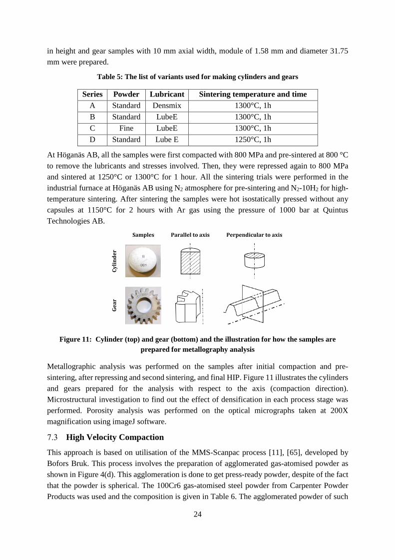
in height and gear samples with 10 mm axial width, module of 1.58 mm and diameter 31.75 mm were prepared.
Table 5: The list of variants used for making cylinders and gears
Series Powder Lubricant Sintering temperature and time A Standard Densmix 1300°C, 1h B Standard LubeE 1300°C, 1h C Fine LubeE 1300°C, 1h D Standard Lube E 1250°C, 1h
At Höganäs AB, all the samples were first compacted with 800 MPa and pre-sintered at 800 °C to remove the lubricants and stresses involved. Then, they were repressed again to 800 MPa and sintered at 1250°C or 1300°C for 1 hour. All the sintering trials were performed in the industrial furnace at Höganäs AB using N2 atmosphere for pre-sintering and N2-10H2 for high-temperature sintering. After sintering the samples were hot isostatically pressed without any capsules at 1150°C for 2 hours with Ar gas using the pressure of 1000 bar at Quintus Technologies AB.
Figure 11: Cylinder (top) and gear (bottom) and the illustration for how the samples are
prepared for metallography analysis
Metallographic analysis was performed on the samples after initial compaction and pre-sintering, after repressing and second sintering, and final HIP. Figure 11 illustrates the cylinders and gears prepared for the analysis with respect to the axis (compaction direction). Microstructural investigation to find out the effect of densification in each process stage was performed. Porosity analysis was performed on the optical micrographs taken at 200X magnification using imageJ software.
High Velocity Compaction
This approach is based on utilisation of the MMS-Scanpac process [11], [65], developed by Bofors Bruk. This process involves the preparation of agglomerated gas-atomised powder as shown in Figure 4(d). This agglomeration is done to get press-ready powder, despite of the fact that the powder is spherical. The 100Cr6 gas-atomised steel powder from Carpenter Powder Products was used and the composition is given in Table 6. The agglomerated powder of such
Samples Parallel to axis Perpendicular to axis
Cyli
nd
er
Gea
r
25
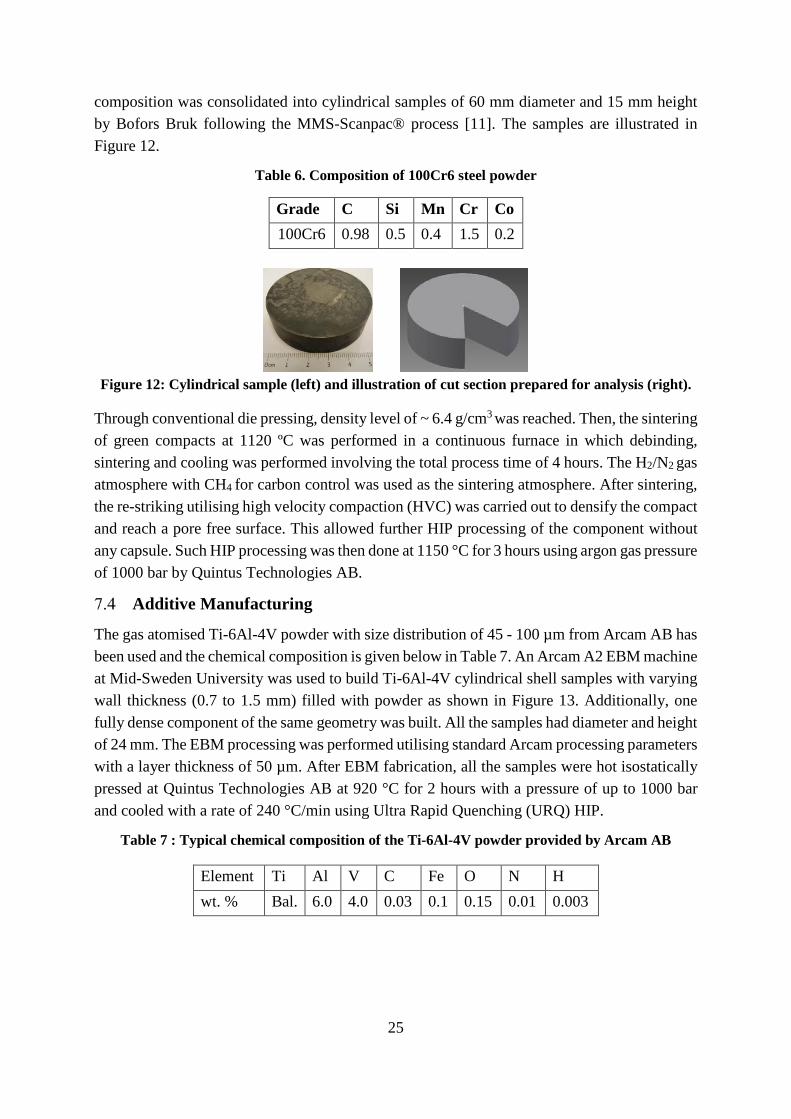
composition was consolidated into cylindrical samples of 60 mm diameter and 15 mm height by Bofors Bruk following the MMS-Scanpac® process [11]. The samples are illustrated in Figure 12.
Table 6. Composition of 100Cr6 steel powder
Figure 12: Cylindrical sample (left) and illustration of cut section prepared for analysis (right).
Through conventional die pressing, density level of ~ 6.4 g/cm3 was reached. Then, the sintering of green compacts at 1120 ºC was performed in a continuous furnace in which debinding, sintering and cooling was performed involving the total process time of 4 hours. The H2/N2 gas atmosphere with CH4 for carbon control was used as the sintering atmosphere. After sintering, the re-striking utilising high velocity compaction (HVC) was carried out to densify the compact and reach a pore free surface. This allowed further HIP processing of the component without any capsule. Such HIP processing was then done at 1150 °C for 3 hours using argon gas pressure of 1000 bar by Quintus Technologies AB.
Additive Manufacturing
The gas atomised Ti-6Al-4V powder with size distribution of 45 - 100 µm from Arcam AB has been used and the chemical composition is given below in Table 7. An Arcam A2 EBM machine at Mid-Sweden University was used to build Ti-6Al-4V cylindrical shell samples with varying wall thickness (0.7 to 1.5 mm) filled with powder as shown in Figure 13. Additionally, one fully dense component of the same geometry was built. All the samples had diameter and height of 24 mm. The EBM processing was performed utilising standard Arcam processing parameters with a layer thickness of 50 µm. After EBM fabrication, all the samples were hot isostatically pressed at Quintus Technologies AB at 920 °C for 2 hours with a pressure of up to 1000 bar and cooled with a rate of 240 °C/min using Ultra Rapid Quenching (URQ) HIP.
Table 7 : Typical chemical composition of the Ti-6Al-4V powder provided by Arcam AB
Element Ti Al V C Fe O N H wt. % Bal. 6.0 4.0 0.03 0.1 0.15 0.01 0.003
Grade C Si Mn Cr Co 100Cr6 0.98 0.5 0.4 1.5 0.2

26
Figure 13: Illustration of EBM built cylindrical shell with different wall thickness, filled with powders
The specimens were cut along the build direction and then ground in five steps (from 240 grit up to 4000 grit with SiC abrasive) followed by polishing using colloidal silica suspension (OP-S) with 10% H2O2 (30% conc.) for 10 min. The samples were chemically etched with Kroll’s Reagent (2% HF+ 2% HNO3) for less than 10 seconds to reveal the microstructure before and after HIP.
Presintered powders after EBM fabrication
Different wall thickness
27
8 RESULTS AND SUMMARY OF PAPERS Liquid Phase Sintering - Paper I
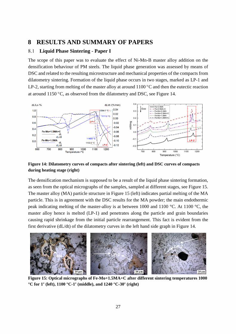
The scope of this paper was to evaluate the effect of Ni-Mn-B master alloy addition on the densification behaviour of PM steels. The liquid phase generation was assessed by means of DSC and related to the resulting microstructure and mechanical properties of the compacts from dilatometry sintering. Formation of the liquid phase occurs in two stages, marked as LP-1 and LP-2, starting from melting of the master alloy at around 1100 °C and then the eutectic reaction at around 1150 °C, as observed from the dilatometry and DSC, see Figure 14.
Figure 14: Dilatometry curves of compacts after sintering (left) and DSC curves of compacts during heating stage (right)
The densification mechanism is supposed to be a result of the liquid phase sintering formation, as seen from the optical micrographs of the samples, sampled at different stages, see Figure 15. The master alloy (MA) particle structure in Figure 15 (left) indicates partial melting of the MA particle. This is in agreement with the DSC results for the MA powder; the main endothermic peak indicating melting of the master-alloy is at between 1000 and 1100 °C. At 1100 °C, the master alloy hence is melted (LP-1) and penetrates along the particle and grain boundaries causing rapid shrinkage from the initial particle rearrangement. This fact is evident from the first derivative (dL/dt) of the dilatometry curves in the left hand side graph in Figure 14.
Figure 15: Optical micrographs of Fe-Mo+1.5MA+C after different sintering temperatures 1000 °C for 1’ (left), 1100 °C-1’ (middle), and 1240 °C-30’ (right)
LP-2
LP-1
LP-2
MA
28
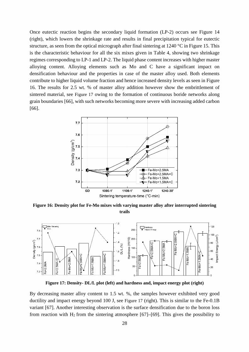
Once eutectic reaction begins the secondary liquid formation (LP-2) occurs see Figure 14 (right), which lowers the shrinkage rate and results in final precipitation typical for eutectic structure, as seen from the optical micrograph after final sintering at 1240 °C in Figure 15. This is the characteristic behaviour for all the six mixes given in Table 4, showing two shrinkage regimes corresponding to LP-1 and LP-2. The liquid phase content increases with higher master alloying content. Alloying elements such as Mo and C have a significant impact on densification behaviour and the properties in case of the master alloy used. Both elements contribute to higher liquid volume fraction and hence increased density levels as seen in Figure 16. The results for 2.5 wt. % of master alloy addition however show the embrittlement of sintered material, see Figure 17 owing to the formation of continuous boride networks along grain boundaries [66], with such networks becoming more severe with increasing added carbon [66].
Figure 16: Density plot for Fe-Mo mixes with varying master alloy after interrupted sintering
trails
Figure 17: Density- DL/L plot (left) and hardness and, impact energy plot (right)
By decreasing master alloy content to 1.5 wt. %, the samples however exhibited very good ductility and impact energy beyond 100 J, see Figure 17 (right). This is similar to the Fe-0.1B variant [67]. Another interesting observation is the surface densification due to the boron loss from reaction with H2 from the sintering atmosphere [67]–[69]. This gives the possibility to

29
perform capsule free HIP to reach full densification. The results obtained clearly indicate that the master alloy addition effectively enhances the densification behaviour. The behaviour during sintering, along with the liquid phase generation, microstructural characteristics and mechanical testing, reveals that the optimised master alloy addition from 2.5 to 1.5 wt. % is necessary for the better performance.
Double Pressing and Double Sintering Approach - Paper II
The scope of this study is to evaluate the limits of double pressing and double sintering in case of optimised powder pre-alloyed with molybdenum. Cylindrical samples and gears were manufactured by Höganäs AB. Characterisation at different stages of the process was then performed as part of this thesis study to evaluate the effect of parameters on the densification after final sintering and HIP as follows:
• Powder size fraction (standard and fine powder) • Lubricant • Sintering temperature • Pressing
The results show that the double pressing and sintering is effective for surface pore closure after sintering at 1300 °C and can be further HIP-processed to full density.
Process:
1P - First pressing
1S - First sintering
2P - Second pressing
2S - Second sintering
HIP - Hot isostatic pressing
Figure 18: Density plot for cylindrical samples showing the increasing density levels with the subsequent process. Sample B, C and D as given in Table 5
Table 8: Summary of the results from Paper II
Parameters Cylinder and Gears samples Lubricant LubeE shows better densification than Densmix for cylindrical samples.
Pressing Double pressing enables the closure of surface pores which provides the surface densified part good enough for HIP to reach full density

30
Powder size fraction
Fine powder fraction shows better densification with smaller pore size and almost full densification after HIP.
Sintering temperature
Sintering at 1300 °C shows similar densification as sintering at 1250°C, even if the higher temperature certainly helps in the surface pore closure. The material can be further HIP processed without any capsule.
Figure 19: Illustration of the gear section with density variation at the middle (left) and Optical
micrograph showing density variation (right)
8.2.1 Neutral Zone For gear samples it is evident that the neutral zone problem persists even after HIP-processing. This phenomenon arises from the first pressing step where the density gradient or variation within the compact arises due to the pressure gradient during compaction along the component height at the tool/powder compact interface. This fact causes low density levels in the middle region in the component surface, see Figure 19. This is evident in the case of coarse powder used for the gear samples. The densification behaviour is also predicted when simulating using FEM by the corresponding author Khodaee of Paper II, by using the same parameters after pressing. From the porosity values of the gears with finer powder (B and C), it can be seen that despite of the slightly higer porosity after first pressing and sintering, these materials show overall better densification after the high-temperature sintering and HIP. The average pore size is comparatively lower than that for the standard powder samples. Considering the geometrical aspects, smaller gear tooth geometry will result in neutral zone due to the incomplete powder filling and this problem can be eliminated for larger gear geometry as observed from the powder pressing simulations.

31
High Velocity Compaction – Paper III
This paper reports on the approach to reach density sufficient for the surface pore closure involving high velocity compaction (HVC) as one of the processing stages for HIP without any capsule to reach full density. The approach is developed by Bofors Bruk applying MMS-Scanpac process [11], [65], in which agglomerated gas-atomised powder is used as the base material. After initial compaction and low temperature sintering, the pores located at between metal particle boundaries are clearly visible, see Figure 20 (left). After HVC re-strike and final HIP, a complete homogenised structure was reached, see Figure 20 (right).
Figure 20 : SEM micrograph after low temperature sintering (left) and fully densified part after
HIP (right)
The examination of the samples, see Figure 21, after each process showed that from the initial density of ~ 84 % of the theoretical density after compaction, density increased up to 97% after HVC re-strike, at which the surface pores were closed and reached ~ 99.4% of the theoretical density after HIP.
Figure 21 : Densification of 100Cr6 after each process
The homogenous microstructure after HIP is obtained. The presence of stable oxides rich in Si and, Cr, surrounding the particle boundaries, was observed. These oxides were not reduced during the sintering. This observation emphasises that the proper control of the sintering

32
atmosphere is necessary to minimize presence of stable oxide particles at particle boundaries. Alternatively, increasing in sintering temperature can be considered to improve the reduction of the stable oxides. The maximum size of the oxide particles observed was around 4-5 µm, while 75 % of the oxide particles were less than 1 µm in size, based on the image analysis.
Additive Manufacturing Approach - Paper IV
This approach is based on the idea of manufacturing complex-shaped components with fine microstructure by combination of AM and HIP. The idea is developed within a joint industry-academia-institute project involving the authors to Paper IV and it is based on the approach to build a shell structures by Electron Beam Melting process (EBM), filled with loose powder, and then densify the so-obtained specimens by means of HIP to reach full densification. This approach significantly minimises the built time by EBM as well as it allows you to produce a well-controlled microstructure, characteristic for HIP compacts. Using EBM, cylindrical shells with varying wall thickness were hence fabricated with powder from the powder bed inside. The result was that the powder inside was pre-sintered and successfully enclosed into the built cylinders. The cylindrical components were then HIP-processed without any capsule to reach full densification with loose-sintered powder inside. Figure 22 (left) shows the fabricated shell with the loosely packed and pre-sintered powder inside. The microstructure of material in the shell part has columnar grains characteristic for EBM built samples [70]. After HIP of these shell samples, see Figure 22 (middle and right), fully densified microstructure has been achieved, hence also eliminating all defects like any finite pores or lack of fusion zones.
Figure 22: Cut section of Shell structure with powders after EBM fabrication (left), after HIP
(middle) and the micrograph of the interface region between shell and powders after HIP (right)
Microstructure coarsening occurred after HIP also for the as-built regions. The microstructure of the densified powder after HIP was equiaxed fine grain structure. The interface between the shell and the internal part showed good bonding without any defects and the clear microstructural distinction is observed. From the testing of different EBM-built wall thicknesses of the samples, it is observed that the critical thickness of > 0.9 mm is necessary for pore or defect free surface, suitable for capsule free HIP.

33
9 CONCLUSIONS The aim of this study has been to summarize and demonstrate recent developments in the conventional powder metallurgy approaches and their combination to develop novel hybrid approaches to reach nearly full density – above 95 % of the full density. Such density level is sufficient enough to provide a sample surface with closed porosity that allows subsequent HIP of the component without any capsule. All the four approaches studied allowed to reach the aimed density levels with their different potential advantages.
The liquid phase sintering using recently developed boron-containing master alloy powder (initially developed at CEIT, Spain) enables the densification to > 95 % of the theoretical density. The molybdenum and carbon have significant impact on the densification and final properties. Microstructural embrittlement occurs when adding 2.5 wt. % master alloy. Carbon addition may also results in significant embrittlement of the final components. Hence, for improved properties, optimised content of boron is needed and it was shown to be around 0.12 wt. % (1.5 wt. % master alloy addition). In addition, surface densification during liquid phase sintering, specifically characteristic for the master alloy, is an advantage that allows subsequent HIP without any capsule to reach full density.
The double pressing and double sintering of standard and fine powders in case of Fe-1.5Mo grade gives the high enough density to close the surface pores and this sequence allows subsequent HIP without capsule. The result is near full density for both processed gears and cylinders. The approach developed originally by Höganäs AB could be potential route for making fully dense PM parts. However, the neutral zone problems associated with the pressing operation needs to be addressed and tuned for successful final densification of parts in all locations by means of HIP.
The high velocity compaction route using agglomerated gas-atomised powder as base material enables to densify alloy powder compacts, i.e. tool steel like 100Cr6, up to density levels of ~97% of the theoretical density with the surface pore closure. Near full density ~99.4% is then reached after HIP without any capsule. The further control of sintering atmosphere is needed for the efficient reduction of oxides.
The additive manufacturing combined with HIP, using electron beam melting process to produce shell structures, allows to reach full density with fine microstructure and at the same time potentially increased productivity in comparison with EBM of solid parts. Compared to traditional HIP of encapsulated powder, this approach also constitutes capacity for increased parts complexity. The EBM-fabricated walls act as a capsule during HIP. The critical wall thickness was shown to be around 1 mm in order to assure successful HIP. The interface between the densified powder inside and the walls had excellent bonding. The shrinkage resulting from the HIP can be compensated by adaptive design of the structures. It can be concluded that the combination of AM and HIP shows potential for manufacture of the complex-shape components with isotropic microstructure.

34
10 FUTURE WORK Liquid Phase Sintering Approach
• There is need for detailed characterisation, starting with the master alloy powders itself to identify the different phases formed within the master alloy as well as the phases evolved during sintering with the steel powders.
• The formation, composition and distribution of the eutectic as well as the effect of different alloying elements have to be studied in details. This will be performed through dedicated characterisation of the different phases utilising EBSD and TEM.
• A tailored master alloy system based on boron will be hence proposed.
Cold Isostatic Pressing Approach
• The integration of the cold isostatic pressing as the part of the PM manufacturing route to reach full density PM components with complex shape and large size, not possible using conventional compaction due to the uniaxial press capacities, is a very interesting approach. Initial trials performed indicate technical possibility and economic feasibility of the approach that will be further developed in the PhD work by the author.
35
11 ACKNOWLEDGEMENTS • First of all, I would like to thank my supervisors Professor Lars Nyborg and Associate
professor Eduard Hryha for the opportunity and the freedom they gave me in my pursuit of Powder Metallurgy that I cherish always.
• Then, I would like to express my gratitude to Dr Seshendra Karamchedu for being a mentor and for the boundless discussions we had.
• Then I want to extend my thanks to Docent Kumar Babu Surreddi for all the support right from my master thesis and showing that anything can be done.
• Höganäs AB is greatly acknowledged for their technical support, especially Sigurd Berg for all the support and thanks to Karin Ljung for helping me with the experiments there.
• Dr. Ola Bergman and Dr. Dimitris Chasoglou from Höganäs AB are also greatly acknowledged.
• Dr. Michael Andersson from Höganäs AB is thanked for his support and co-operation within the HIPGEAR project.
• Christer Åslund, Bofors Bruk and Dr. Lars Erik Rännar from Mid Sweden University are greatly acknowledged for supporting with the materials and experiments for this study.
• Magnus Ahlfors from Quintus Technologies AB is greatly acknowledged for all the HIP trails and collaboration.
• Dr. Hans Magnusson from Swerea KIMAB is greatly acknowledged for all the discussions and collaboration within the framework of several projects.
• All the co-authors, academic and industrial partners within the several projects of the articles are greatly acknowledged.
• Support from Sweden’s innovation agency VINNOVA in the following projects are greatfully acknowledged Dnr: 2010-01619, High-performance sintered steels with high density and dimension
control – next generation sintered steels (HIPERSINT) Dnr: 2013-05594, Innovative powder based manufacturing of gear wheels with high
performance (HIPGEAR) Dnr: 2013-03299, Novel sintering strategy for the competitive manufacturing of the
high-performance PM components (COMPRESINT) Dnr: 2014-00795, Innovative components manufacturing technology through powder
technology (in the frame of VINNOVA’s challenge driven innovation program) • Thanks are extended to Dr. Yiming Yao, Dr. Eric Tam, and Roger Sagdahl for the
continuous help and solving any technical difficulties with the analysis and instruments. • All the colleagues at the Department of Materials and Manufacturing Technology are
greatly acknowledged and thanks to especially Associate Professor Johan Ahlström, Giulio, Associate Professor Sheng Guo, Dr. Amir, Dr. Ruslan, Johan Wendel, for all the interesting discussions and Swathi for proof reading this thesis.
• A special thanks to my wife Brindha and my grandparents and parents for all the support.
36
12 REFERENCES [1] W. Schatt and K. P. Wieters, Powder Metallurgy - Processing and Materials.
Shrewsbury: EPMA, 1997.
[2] “World PM2016: Current status and future outlook for the global PM industry reviewed in Hamburg,” Powder Metallurgy Review, pp. 47–51, 2016.
[3] R. M. German, Powder Metallurgy of Iron and Steel. Wiley-Interscience, 1998.
[4] J. R. Dale, “Powder Metallurgy -Intrinsically Sustainable,” Int. J. Powder Metall., vol. 47, no. 1, pp. 27–31, 2011.
[5] M. Vattur Sundaram, H. Karlsson, K. B. Surreddi, E. Hryha, M. Andersson, G. Åkerström, and L. Nyborg, “Investigation of Low Temperature Creep Behaviour of PM Steels,” Powder Metall. Prog., vol. 14, no. 2, pp. 67–72, 2014.
[6] “Powder Metallurgy Market Trends.” [Online]. Available: http://www.strategyr.com/MarketResearch/Powder_Metallurgy_Market_Trends.asp. [Accessed: 22-Mar-2016].
[7] M. Ahlfors, “The Possibilities and Advantages with Heat Treatments in HIP,” in HIP14 Proceedings, 2014.
[8] M. Sarasola, S. Sainz, and F. Castro, “Liquid Phase Sinterng of PM Steels Through Boron-Containing Master Alloy Additions,” in Euro PM 2005, 2005, vol. 1, pp. 349–356.
[9] A. Veiga, “Development of high performance nickel or boron PM steels respectively obtained after solid state and liquid phase sintering-PhD Thesis,” University of Navarra, San Sebastian, Spain, 2015.
[10] A. Flodin, M. Andersson, and A. Miedzinski, “Full density powder metal components through Hot Isostatic Pressing,” Met. Powder Rep., pp. 2–5, 2016.
[11] C. Åslund, “New PM Process with Wrought Steel properties,” in Euro PM2012-PM Improving compaction and Shaping, 2012.
[12] ASM International, ASM Handbook Vol 07 Powder Metal Technologies and Applications, vol. 7. 2015.
[13] C. Åslund and C. Quichaud, “Metallic powder for producing pieces by compression and sintering, and a process for obtaining this powder-US Patent,” 5460641, 1995.
[14] “Production of Sintered Components,” in Höganäs Handbook 2, Höganäs AB, 2004.
[15] W. Brian James, “High performance ferrous PM materials for automotive applications,” Met. Powder Rep., vol. 46, no. 9, pp. 26–32, Sep. 1991.
[16] U. Engström, C. Lindberg, and J. Tengzelius, “Powders and processes for high performance PM steels,” Powder Metall., vol. 35, no. 1, pp. 67–73, 1992.
[17] C. Recknagel, A. Marquardt, I. Langer, S. Müller, and B. Kieback, “Higher Densities of PM-Steels by Warm Secondary Compaction and Sizing,” Proc. EURO PM 2011, 2011.
[18] S. Karamchedu, “Critical Aspects of Delubrication and Sintering of Chromium-alloyed Powder Metallurgy Steels-PhD Thesis,” Chalmers University of Technology, 2015.
[19] H. Karlsson, “Role of surface oxides in sintering of chromium-alloyed steel powder-PhD Thesis,” Chalmers University of Technology, 2005.

37
[20] D. Chasoglou, “Surface Chemical Characteristics of Chromium-alloyed Steel Powder and the Role of Process Parameters during Sintering-PhD Thesis,” Chalmers University of Technology, 2012.
[21] O. Bergman, “Key Aspects of Sintering Powder Metallurgy Steel Prealloyed with Chromium and Manganese-PhD Thesis,” Chalmers University of Technology, 2011.
[22] W. B. James, “What is Sinter-Hardening?,” in International Conference on Powder Metallurgy & Particlulate Materials PM2TEC, 1998, vol. 98, pp. 55–60.
[23] A. Liersch, H. Danninger, and R. Ratzi, “The Role of Admixed Hexagonal Boron Nitride in Sintered Steels 2 . Effect on Sliding Wear and Machinability,” Powder Metall. Prog., vol. 7, no. 2, p. 2007, 2007.
[24] F. Hanejko, “High Density via Single Pressing / Single Sintering,” Powder Metall. Technol., vol. 28, no. 1, pp. 73–76, 2010.
[25] C. Oikonomou, E. Hryha, Å. Ahlin, and L. Nyborg, “Effect of Powder Properties on the Compressibility of Water-Atomized Iron and Low-Alloyed Steel Grades,” in Euro PM2013, 2013, vol. 2, pp. 205–212.
[26] E. Hryha, E. Dudrova, and S. Bengtsson, “Influence of powder properties on compressibility of prealloyed atomised powders,” Powder Metall., vol. 51, no. 4, pp. 340–342, 2008.
[27] F. J. Semel and D. A. Lados, “Porosity analysis of PM materials by helium pycnometry,” Powder Metall., vol. 49, no. 2, pp. 173–182, Jun. 2006.
[28] P. Beiss, “Iron and steel: manufacturing route, chap 5, structural mass production,” in Landolt-Börnstein—Group VIII Advanced Materials and Technologies, 2003, pp. 5–20.
[29] Höganäs Handbook for Sintered Components-3.Design and Mechanical Properties. Höganäs AB, 2004.
[30] G. F. Bocchini, “The influence of porosity on the characteristics of sintered materials,” Int. J. powder Metall., vol. 22, no. 3, pp. 185–202, 1986.
[31] H. Danninger, G. Jangg, P. Beiss, and R. Stickler, “Microstructure and mechanical properties of sintered iron. II: Experimental study,” PMI. Powder Metall. Int., vol. 25, no. 5, pp. 219–223, 1993.
[32] H. G. Rutz and F. G. Hanejko, “High density processing of high performance ferrous materials,” Adv. Powder Metall. Part. Mater., vol. 5, p. 117, 1994.
[33] I. Hauer, M. Larsson, and U. Engström, “Properties of high-strength PM materials obtained by different compaction methods in combination with high temperature sintering,” Adv. Powder Metall. Part. Mater., vol. 8, pp. 8–29, 2002.
[34] N. Chawla, J. J. Williams, X. Deng, C. Mcclimon, L. Hunter, and S. H. Lau, “Three-dimensional characterization ahd modeling of porosity in PM steels,” Int. J. Powder Metall. (Princeton, New Jersey), vol. 45, no. 2, pp. 19–27, 2009.
[35] E. Hryha and L. Nyborg, “Thermogravimetry study of the effectiveness of different reducing agents during sintering of Cr-prealloyed PM steels,” J. Therm. Anal. Calorim., Jul. 2014.
[36] M. Vattur Sundaram, S. Karamchedu, C. Gouhier, E. Hryha, and L. Nyborg, “Vacuum sintering studies on chromium alloyed PM steels,” in WORLD PM 2016, 2016.

38
[37] B. Dubrujeaud, M. Vardavoulias, and M. Jeandin, “The role of porosity in the dry sliding wear of a sintered ferrous alloy,” Wear, vol. 174, no. 1–2, pp. 155–161, 1994.
[38] X. Li, “Efficiency and wear properties of spur gears made of powder metallurgy materials-PhD Thesis,” KTH Royal Institute of Technology, 2016.
[39] C. Menapace, a. Molinari, J. Kazior, and T. Pieczonka, “Surface self-densification in boron alloyed austenitic stainless steel and its effect on corrosion and impact resistance,” Powder Metall., vol. 50, no. 4, pp. 326–335, Dec. 2007.
[40] L. Forden, S. Bengtsson, and M. Bergström, “High performance gears,” in Euro PM2004, 2004.
[41] R. Haynes, “Effects of porosity on the tensile strengths of sintered irons,” Met. Powder Rep., vol. 46, no. 2, pp. 49–51, Feb. 1991.
[42] X. Xu, W. Yi, and R. M. German, “Densification and strength evolution in solid-state sintering. Part I Experimental investigation,” J. Mater. Sci., vol. 37, no. 3, pp. 567–575, 2002.
[43] E. Dudrova and M. Kabátova, “A review of failure of sintered steels: fractography of static and dynamic crack nucleation, coalescence, growth and propagation,” Powder Metall., vol. 59, no. 2, pp. 148–167, 2016.
[44] M. Dlapka, H. Danninger, C. Gierl, and B. Lindqvist, “Defining the pores in PM components,” Met. Powder Rep., vol. 65, no. 2, pp. 30–33, Feb. 2010.
[45] K. . Narasimhan, “Sintering of powder mixtures and the growth of ferrous powder metallurgy,” Mater. Chem. Phys., vol. 67, no. 1–3, pp. 56–65, Jan. 2001.
[46] P. Skoglund, “High density PM parts by high velocity compaction,” Powder Metall., vol. 44, no. 3, p. 199, 2001.
[47] P. Jonsén, H. Å. Häggblad, L. Troive, J. Furuberg, S. Allroth, and P. Skoglund, “Green Body Behaviour of High Velocity Pressed Metal Powder,” Mater. Sci. Forum, vol. 534–536, pp. 289–292, 2007.
[48] C. Åslund and A. Eklund, “Preform CIP for fully dense PM parts,” in PowderMet 2012, 2012, pp. 3126–3132.
[49] R. Tandon and J. Johnson, “Liquid Phase Sintering,” in ASM Handbook, Volume 7 - Powder Metal Technologies and Applications, vol. 7, 1998, pp. 565–573.
[50] R. M. German, Sintering Theory and Practice. New York: John Wiley & Sons, Inc., 1996.
[51] R. M. German, Liquid Phase Sintering. Springer Science & Business Media, 1985.
[52] A. Veiga and F. Castro, “Master Alloys for High Strength PM Steels,” World PM2012 Proc., no. 2, 2012.
[53] F. Castro, S. Sainz, A. Veiga, and P. Ortiz, “The Master Alloy Concept and its Consequences,” in Advances in Powder Metallurgy and Particulate Materials - 2012, 2012.
[54] A. Veiga, C. Bilbao, S. Sainz, and F. Castro, “Controlled Shrinkage of Low Alloyed PM Steels During LPS,” in PowderMet2015, 2015.
[55] G. Zapf, G. Hoffmann, and K. Dalal, “Effect of additional alloying elements on the properties of sintered manganese steels,” Powder Metall., vol. 18, no. 35, pp. 214–236,

39
Mar. 1975.
[56] J. Klein, “Preliminary investigation of liquid phase sintering in ferrous systems,” California Univ., Berkeley (USA). Lawrence Berkeley Lab., 1975.
[57] D. S. Madan and R. M. German, “Enhanced Sintering for Ferrous Components,” in Modern Developments in Powder Metallurgy., 1984, vol. 15, pp. 441–454.
[58] K. S. Narasimhan and F. J. Semel, “Sintering of Powder Premixes-A Brief Overview,” Adv. POWDER Metall. Part. Mater., vol. 1, p. 5, 2007.
[59] R. M. German, K. S. Hwang, and D. S. Madan, “Analysis of Fe-Mo-B sintered alloys,” Powder Metall. Int., vol. 19, no. 2, pp. 15–18, 1987.
[60] M. Selecká, A. Šalak, and H. Danninger, “The effect of boron liquid phase sintering on properties of Ni-, Mo- and Cr-alloyed structural steels,” J. Mater. Process. Technol., vol. 141, no. 3, pp. 379–384, Nov. 2003.
[61] A. K. Mashkov, V. I. Gurdin, and E. P. Polyakov, “A boron-containing material for the infiltration of iron compacts,” Sov. Powder Metall. Met. Ceram., vol. 18, no. 5, pp. 344–346, 1979.
[62] L. Lozada and F. Castro, “Controlled densification of boron-containing stainless steels,” in Advances in Powder Metallurgy and Particulate Materials, 2011, pp. 778–788.
[63] J. C. Rodriguez, L. Lozada, C. Tojal, T. Gómez-Acebo, and F. Castro, “Thermodynamic Aspects of Liquid Phase Sintering B-Containing P/M Stainless Steels,” Solid State Phenom., vol. 172–174, pp. 1164–1170, 2011.
[64] D. Richter, G. Haour, and D. Richon, “Hot isostatic pressing (HIP),” Mater. Des., vol. 6, no. 6, pp. 303–305, Dec. 1985.
[65] C. Aslund, “Sintered scanpac powders outperforms wrought stainless steels,” in PowderMet 2009, 2009, pp. 938–962.
[66] C. Gierl-mayer, J. Zbiral, and H. Danninger, “Enhanced Sintering of PM Steels by Addition of Fe-Ni-B Masteralloy,” in Euro PM2014, 2014, pp. 1–6.
[67] V. Vassileva, H. Danninger, S. Strobl, and C. Gierl, “Atmosphere Effects on Sintering of Ferrous Powder Compacts Containing Boron,” in Euro PM2007, 2007, vol. 1, no. 1, pp. 53–58.
[68] C. Menapace, A. Molinari, J. Kazior, and T. Pieczonka, “Surface phenomena on boron alloyed astaloy CrM powders,” in Euro PM 2007, 2007, vol. 1, pp. 41–46.
[69] J. Karwan-Baczewska, “The properties of Fe-Ni-Mo-Cu-B materials produced via liquid phase sintering,” Arch. Metall. Mater., vol. 56, no. 3, pp. 789–796, 2011.
[70] X. Tan, Y. Kok, Y. J. Tan, M. Descoins, D. Mangelinck, S. B. Tor, K. F. Leong, and C. K. Chua, “Graded microstructure and mechanical properties of additive manufactured Ti–6Al–4V via electron beam melting,” Acta Mater., vol. 97, pp. 1–16, Sep. 2015.