processor expert - user guide - nxp...
TRANSCRIPT
Processor Expert User Guide
Document Number: QCSPEXUGRev 4.0, 08/2014

Processor Expert User Guide, Rev. 4.0, 08/2014
2 Freescale Semiconductor, Inc.

Contents
Section number Title Page
Chapter 1Introduction
1.1 Overview...........................................................................................................................................................................7
1.2 Features.............................................................................................................................................................................7
1.3 Benefits............................................................................................................................................................................. 8
1.4 Concepts............................................................................................................................................................................8
Chapter 2User Interface
2.1 User Interface.................................................................................................................................................................... 0
2.2 Main Menu........................................................................................................................................................................11
2.2.1 Project Pop-up Menu............................................................................................................................................. 12
2.2.2 Processor Expert Options.......................................................................................................................................12
2.2.2.1 Project Options.........................................................................................................................................12
2.2.2.2 Preferences............................................................................................................................................... 13
2.3 Components View.............................................................................................................................................................15
2.3.1 View Menu.............................................................................................................................................................17
2.3.2 Popup Menu........................................................................................................................................................... 17
2.4 Components Library View................................................................................................................................................19
2.4.1 Modes.....................................................................................................................................................................19
2.4.2 Filtering..................................................................................................................................................................20
2.4.3 Pop-up Menu..........................................................................................................................................................20
2.4.4 Component Assistant............................................................................................................................................. 21
2.5 Component Inspector View.............................................................................................................................................. 22
2.5.1 Read Only Items.....................................................................................................................................................23
2.5.2 View Mode Buttons............................................................................................................................................... 23
2.5.3 View Menu.............................................................................................................................................................23
2.5.4 Graphical Mode......................................................................................................................................................24
2.5.5 Pop-up Menu..........................................................................................................................................................24
Processor Expert User Guide, Rev. 4.0, 08/2014
Freescale Semiconductor, Inc. 3
Section number Title Page
2.5.6 Inspector Items.......................................................................................................................................................25
2.5.7 Items Visibility.......................................................................................................................................................27
2.5.8 Configuration Inspector......................................................................................................................................... 28
2.5.8.1 Properties................................................................................................................................................. 28
2.6 Processor View................................................................................................................................................................. 29
2.6.1 Control Buttons...................................................................................................................................................... 30
2.6.1.1 Pins...........................................................................................................................................................31
2.6.1.2 Hints......................................................................................................................................................... 31
2.6.1.3 Shared Pins...............................................................................................................................................32
2.6.1.4 On-chip Peripherals..................................................................................................................................32
2.6.1.4.1 Peripheral or Pin Pop-up Menu...............................................................................................33
2.7 Memory Map View...........................................................................................................................................................34
2.8 Configuration Registers View...........................................................................................................................................34
Chapter 3Using Processor Expert
3.1 Create Project....................................................................................................................................................................37
3.1.1 Select Components.................................................................................................................................................37
3.1.2 Configure Components.......................................................................................................................................... 38
3.1.3 Verify Settings....................................................................................................................................................... 38
3.1.4 Generate Code........................................................................................................................................................38
3.1.5 Build and Debug.................................................................................................................................................... 39
3.2 Basic Principles.................................................................................................................................................................39
3.2.1 Embedded Components......................................................................................................................................... 39
3.2.1.1 Easy Initialization.................................................................................................................................... 40
3.2.1.2 Easy On-chip Peripherals Management...................................................................................................40
3.2.1.3 Component Categories.............................................................................................................................41
3.2.1.4 Levels of Abstraction............................................................................................................................... 41
3.2.2 SoC Components....................................................................................................................................................42
Processor Expert User Guide, Rev. 4.0, 08/2014
4 Freescale Semiconductor, Inc.
Section number Title Page
3.3 Configuring Components..................................................................................................................................................43
3.3.1 Configurations........................................................................................................................................................43
3.3.2 Design Time Checking...........................................................................................................................................43
3.3.3 Creating User Component Templates.................................................................................................................... 44
3.3.4 Signal Names......................................................................................................................................................... 45
3.3.4.1 Documentation......................................................................................................................................... 45
3.4 Component Inheritance and Component Sharing............................................................................................................. 46
3.4.1 Inheritance..............................................................................................................................................................47
3.4.2 Settings in Processor Expert.................................................................................................................................. 47
3.4.3 Component Sharing................................................................................................................................................48
3.4.4 Settings in Processor Expert.................................................................................................................................. 48
3.4.5 Run-time Resources Allocation............................................................................................................................. 48
3.5 Sharing Pins Among Peripherals...................................................................................................................................... 49
3.5.1 ConnectPin Method................................................................................................................................................49
3.6 Export and Import.............................................................................................................................................................49
3.6.1 Export Component Settings................................................................................................................................... 50
3.6.2 Export Board Configuration...................................................................................................................................52
3.6.3 Import Component Settings................................................................................................................................... 54
3.6.4 Apply Board Configuration................................................................................................................................... 57
3.6.5 Import Component(s) from Package......................................................................................................................58
3.7 Code Generation and Usage..............................................................................................................................................60
3.7.1 Files Produced by Processor Expert.......................................................................................................................60
3.7.2 Tracking Changes in Generated Code................................................................................................................... 61
3.8 PE Project File.................................................................................................................................................................. 62
3.8.1 Project Directory Structure.................................................................................................................................... 63
Processor Expert User Guide, Rev. 4.0, 08/2014
Freescale Semiconductor, Inc. 5

Processor Expert User Guide, Rev. 4.0, 08/2014
6 Freescale Semiconductor, Inc.

Chapter 1Introduction
It describes how to get started with the Processor Expert tool.
The document also makes you familiar with the user interface of Processor Expert.
This chapter explains:
• Overview• Features• Benefits• Concepts
1.1 Overview
Both hardware and software design have progressed with the ever-advancing newtechnologies emerging everyday, but their interrelationships and interdependence havebeen mostly neglected. On one hand, you often see a good new hardware architecture, butthe software design is too expensive for such an architecture. On the other hand, thecomputerization of nearly all mechanical gadgets all over the modern world leads to theuse of embedded computer systems. In situations where expense is a consideration,
embedded computer systems with efficient software can significantly reduce the overalldesign cost. Processor Expert is designed for rapid application development of embeddedapplications for a wide range of processors.
1.2 Features
The key features of Processor Expert are:
Processor Expert User Guide, Rev. 4.0, 08/2014
Freescale Semiconductor, Inc. 7

• Includes a library of embedded system building blocks• Created from Embedded Components• Provides built-in SOC verification system for verifying component settings• Supports automatic configuration management and data generation• Easy to use graphical user interface• Integrated into Eclipse environment
1.3 Benefits
The benefits of Processor Expert are:
• Embedded Components encapsulate the functionality of basic elements of embeddedsystems, such as CPU core, on-chip peripherals, FPGA, standalone peripherals,virtual devices, and pure software algorithms, and change these facilities toproperties, methods, and events such as objects in OOP.
• The Peripheral Initialization components of Processor Expert generate effectiveinitialization code for all on-chip devices and support all their features.
• Processor Expert allows easy examination of the details of the architecture and therelationship between the Embedded Component setup and processor's controlregisters initialization.
1.4 Concepts
Embedded device's configuration or functionality is separated into building blocks calledEmbedded Components. The Processor Expert application is created from EmbeddedComponents. These components generate a source code or data files for initialization andconfiguration of selected Freescale silicon. They have an interface similar to the object-oriented programming models that consists of:
• Properties - to modify or customize the object behavior. You can control propertiesin design time by using the Component Inspector.
• Methods (not used in this version) - the procedures that can be executed inapplication code and function calls.
• Events (not used in this version) - the interfacing hardware or software events whichare invoked by the component to the user's code.
Benefits
Processor Expert User Guide, Rev. 4.0, 08/2014
8 Freescale Semiconductor, Inc.
The Embedded Components have a subset called as Peripheral Initialization Components,which allow you to setup initialization of the particular on-chip device to any possiblemode of operation. You can easily view all initialization values of the processor producedby Processor Expert with highlighted differences between the last and current propertiessettings.
Processor Expert performs a design time checking of the settings of all components andreports errors and warnings notifying you about wrong property values or conflicts in thesettings with other components in the project.
Processor Expert contains many useful tools for exploring a structure of the targetprocessor showing the details about the allocated on-chip peripherals and pins. Itgenerates a ready-to-use code or the data files initializing all on-chip peripherals used bythe component according to the component setup.
Chapter 1 Introduction
Processor Expert User Guide, Rev. 4.0, 08/2014
Freescale Semiconductor, Inc. 9

Concepts
Processor Expert User Guide, Rev. 4.0, 08/2014
10 Freescale Semiconductor, Inc.

Chapter 2User Interface
The Processor Expert menu is integrated as a plugin in the Eclipse IDE providing set ofviews.
The Eclipse IDE main menu has a menu item named Processor Expert.
The user interface of Processor Expert consists of the following views:
• Component Inspector - Allows you to setup components of the project.• Component Library - Shows all supported components including processor
components and component templates.• Configuration Registers - Shows overview of the peripheral initialization settings for
the current processor.• Memory Map - Shows the processor address space and internal and external memory
mapping.• Components - Shows an embedded component that can be used in Processor Expert.• Processor - The processor used in a given project.
This chapter explains:
• Main Menu• Components View• Components Library View• Components Inspector View• Processor View• Memory Map View• Configuration Registers View
2.2 Main Menu
Processor Expert User Guide, Rev. 4.0, 08/2014
Freescale Semiconductor, Inc. 11
The Processor Expert plugin is integrated into the Eclipse IDE as plugin application. TheIDE main menu contains a new menu item named Processor Expert.
The Processor Expert menu includes:
• Show views - Shows standard Processor Expert windows in case they are hidden.• Hide views - Hides Processor Expert views.• Import Component(s) from Package - This command allows to select and install
Processor Expert update packages ( .PEUpd) files. These files can be created in CDEby exporting a user's component.
2.2.1 Project Pop-up Menu
This menu is available on right-clicking at the ProcessorExpert.pe file. It contains thestandard commands with the Processor Expert specific command:
Generate Processor Expert Code - Invokes code generation for the current project. Thegenerated files are automatically inserted into the active (default) target in the QorIQConfiguration project. Generated files corresponding to the Embedded Components canbe accessed from the Generated_Code folder. For more details, refer to the CodeGeneration and Usage topic.
For Processor Expert related settings and options, refer to the Processor Expert Options.
2.2.2 Processor Expert Options
This section contains the following topics:
• Project Options• Preferences
2.2.2.1 Project Options
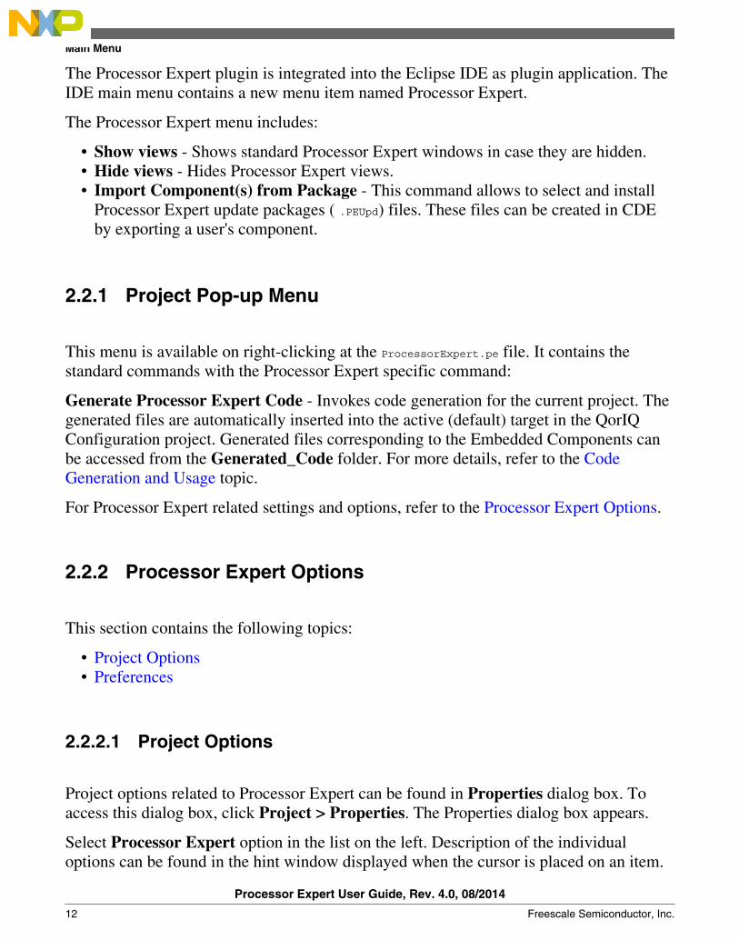
Project options related to Processor Expert can be found in Properties dialog box. Toaccess this dialog box, click Project > Properties. The Properties dialog box appears.
Select Processor Expert option in the list on the left. Description of the individualoptions can be found in the hint window displayed when the cursor is placed on an item.
Main Menu
Processor Expert User Guide, Rev. 4.0, 08/2014
12 Freescale Semiconductor, Inc.
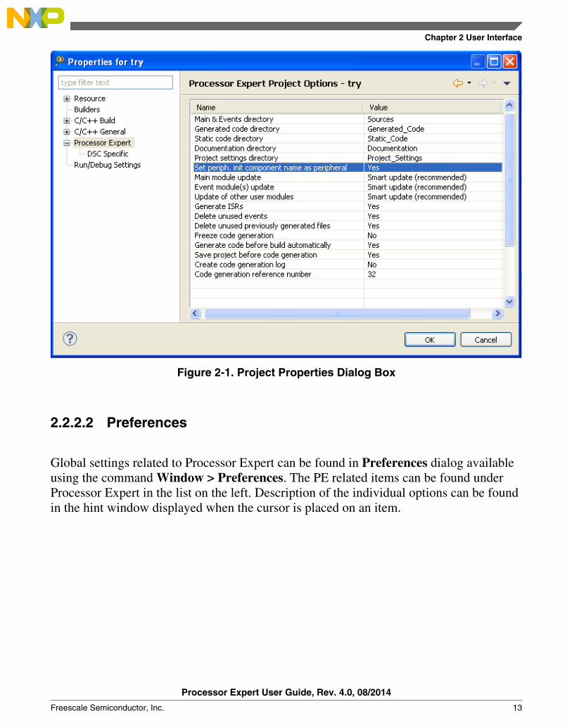
Figure 2-1. Project Properties Dialog Box
2.2.2.2 Preferences
Global settings related to Processor Expert can be found in Preferences dialog availableusing the command Window > Preferences. The PE related items can be found underProcessor Expert in the list on the left. Description of the individual options can be foundin the hint window displayed when the cursor is placed on an item.
Chapter 2 User Interface
Processor Expert User Guide, Rev. 4.0, 08/2014
Freescale Semiconductor, Inc. 13
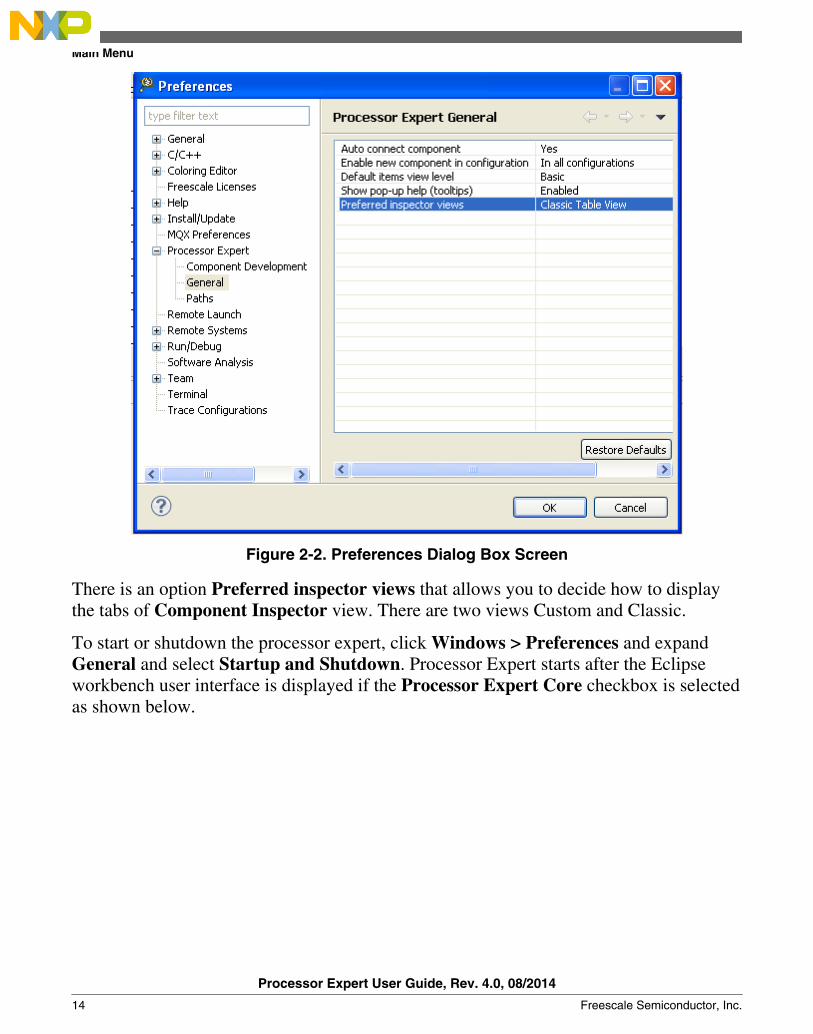
Figure 2-2. Preferences Dialog Box Screen
There is an option Preferred inspector views that allows you to decide how to displaythe tabs of Component Inspector view. There are two views Custom and Classic.
To start or shutdown the processor expert, click Windows > Preferences and expandGeneral and select Startup and Shutdown. Processor Expert starts after the Eclipseworkbench user interface is displayed if the Processor Expert Core checkbox is selectedas shown below.
Main Menu
Processor Expert User Guide, Rev. 4.0, 08/2014
14 Freescale Semiconductor, Inc.
Figure 2-3. Preferences - Startup and Shutdown
2.3 Components View
To open this view, click Window > Show View > Other... and select Processor Expert> Components.
Components view shows the tree with the following items:
• Generator_Configurations - Configurations of the project.
Chapter 2 User Interface
Processor Expert User Guide, Rev. 4.0, 08/2014
Freescale Semiconductor, Inc. 15
• Operating System - contains special components that provide operating systeminterface and configuration if there are any used.
• Processors - contains processor components included in the project.• Components - it is included in the project. Every component inserted in the project
is displayed in the Component Inspector view and may have a sub tree showingitems available for the component (note that components can offer only some or evennone of these items):
• Methods - Methods allow runtime control of the component's functionality.• Events routines - Events allow handling of the hardware or software events
related to the component. If the event is disabled, the name of the event isshown. For enabled events, the name of the handling function is shown.
• ISRs - Represent component-related interrupt routines that is created by you forlow-level interrupt processing. For items, whose ISR names have been specifiedwithin component settings, a user-specified name of an ISR and name of theinterrupt vector is shown. If an ISR name is not specified (interrupt has to bedisabled in this case), only the interrupt vector name is present.
All component's items have status icons that signify the enabled or disabled state. If thisstate cannot be changed directly, the background of the icon is gray. For more details,refer to the Embedded Components topic.
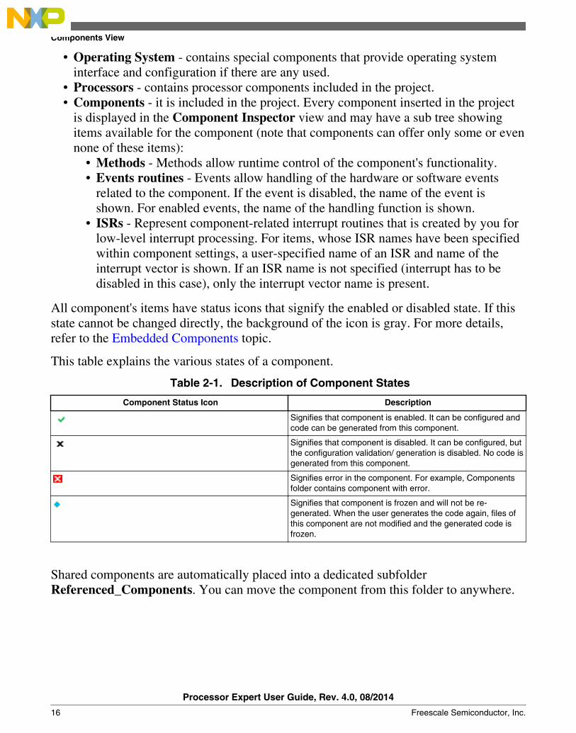
This table explains the various states of a component.
Table 2-1. Description of Component States
Component Status Icon Description
Signifies that component is enabled. It can be configured andcode can be generated from this component.
Signifies that component is disabled. It can be configured, butthe configuration validation/ generation is disabled. No code isgenerated from this component.
Signifies error in the component. For example, Componentsfolder contains component with error.
Signifies that component is frozen and will not be re-generated. When the user generates the code again, files ofthis component are not modified and the generated code isfrozen.
Shared components are automatically placed into a dedicated subfolderReferenced_Components. You can move the component from this folder to anywhere.
Components View
Processor Expert User Guide, Rev. 4.0, 08/2014
16 Freescale Semiconductor, Inc.
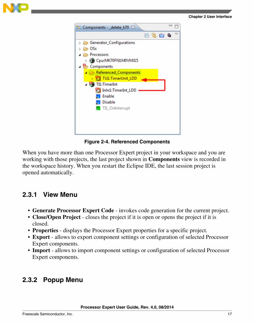
Figure 2-4. Referenced Components
When you have more than one Processor Expert project in your workspace and you areworking with those projects, the last project shown in Components view is recorded inthe workspace history. When you restart the Eclipse IDE, the last session project isopened automatically.
2.3.1 View Menu
• Generate Processor Expert Code - invokes code generation for the current project.• Close/Open Project - closes the project if it is open or opens the project if it is
closed.• Properties - displays the Processor Expert properties for a specific project.• Export - allows to export component settings or configuration of selected Processor
Expert components.• Import - allows to import component settings or configuration of selected Processor
Expert components.
2.3.2 Popup Menu
Chapter 2 User Interface
Processor Expert User Guide, Rev. 4.0, 08/2014
Freescale Semiconductor, Inc. 17
• Inspector - opens Component Inspector view for the component. For more details,refer to the Component Inspector View topic.
• Inspector - Pinned - opens Component Inspector view for the component in"pinned" mode. This command allows to have several inspector views for differentcomponents opened at once. For more details, refer to the Component InspectorView topic.
• Code Generation - allows to disable/enable the generated module for the componentand CPU component.
• Configuration Registers - displays the Configuration Registers view for theperipheral initialized by the selected component. For more details, refer to theConfiguration Registers View topic.
• Target Processor Package - displays the Processor view for the processor derivativeused in a given project.
• Processor Memory Map - displays the Memory Map view for the processor addressspace and internal and external memory mapping.
• Rename Component - changes the name of the component.• Select Distinct/ Shared mode - switches between shared and distinct mode of the
component. This setting is available for LDD components only.• Open File - opens the generated code from the selected component for the source
code editor. Note that the code is available only after successful code generation.• Component Enabled - enables/disables component in the project.• Copy/Paste - components can be copied and pasted inside the same project, between
two projects in the same workspace, and between two projects having each project inseparate workspace.
• Remove component from project - deletes the component from the project.• Help on component - shows a help page for the component.• Save Component Settings As Template - creates a template of the selected
component. For more details, refer to the Creating User Component Templates topic.• Hot key Delete is used for deleting components from the project.• View Code - Opens code editor at the code of the selected method or event.• Toggle Enable/Disable - Enables/Disables the Method or Event.
Components View
Processor Expert User Guide, Rev. 4.0, 08/2014
18 Freescale Semiconductor, Inc.
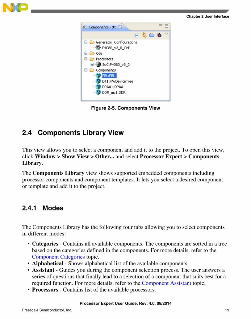
Figure 2-5. Components View
2.4 Components Library View
This view allows you to select a component and add it to the project. To open this view,click Window > Show View > Other... and select Processor Expert > ComponentsLibrary.
The Components Library view shows supported embedded components includingprocessor components and component templates. It lets you select a desired componentor template and add it to the project.
2.4.1 Modes
The Components Library has the following four tabs allowing you to select componentsin different modes:
• Categories - Contains all available components. The components are sorted in a treebased on the categories defined in the components. For more details, refer to theComponent Categories topic.
• Alphabetical - Shows alphabetical list of the available components.• Assistant - Guides you during the component selection process. The user answers a
series of questions that finally lead to a selection of a component that suits best for arequired function. For more details, refer to the Component Assistant topic.
• Processors - Contains list of the available processors.
Chapter 2 User Interface
Processor Expert User Guide, Rev. 4.0, 08/2014
Freescale Semiconductor, Inc. 19
Component names are colored black and the component template names are colored blue.The components that are not supported for the currently selected target processor aregray. By double-clicking on the component, it is possible to insert the component into thecurrent project. The description of the component is shown in a hint.
2.4.2 Filtering
You can activate or deactivate the filtering icon.
Filter can be activated using the filtering icon. If it is active, only the components thatcould be used with the currently selected target processors are shown.
If the filter is inactive, Processor Expert also shows components that are not available forthe current processor.
2.4.3 Pop-up Menu
A pop-up menu opens by right-clicking a component or folder. It contains the followingcommands:
• Add to project - Adds the component to the current project.• Add to project with wizard - Adds the component to the current project and opens a
configuration wizard.• Expand all - Expands the folder and all its subfolders.• Collapse all - Collapses the folder and all its subfolders.• Refresh - Refreshes the view area.• Delete - Only user templates and components are deleted. User component is deleted
from the User Working Directory, from the Beans sub-directory. See ProcessorExpert Eclipse console for the location of the User Working Directory. Other fileslike *.inc, *.drv, *.src remain intact.
• Help on component - Opens help information for the selected component.
Components Library View
Processor Expert User Guide, Rev. 4.0, 08/2014
20 Freescale Semiconductor, Inc.

Figure 2-6. Component Library View
2.4.4 Component Assistant
It guides you during the selection of components while creating basic applicationbuilding blocks.
The Component Assistant is a mode of Components Library view. You will have toanswer a series of questions that finally lead to a selection of a component that suits bestfor a required function. In this mode, the Components Library view consists of thefollowing parts:
• History navigation buttons and the history line showing answers for alreadyanswered questions. You can walk through the history using the arrow buttons or byclicking the individual items.
• A box with a current question.• A list of available answers for the current question.
If the answer already corresponds to a single component (it has an icon of thecomponent and there is a [component name] at the end of the list line) and userdouble-clicks it, it is added into the project. Also, you can right-click on the line toopen the pop-up menu of the component, allowing to add it into the project or viewits documentation (for details, refer to the Components Library View topic).
Chapter 2 User Interface
Processor Expert User Guide, Rev. 4.0, 08/2014
Freescale Semiconductor, Inc. 21

If more questions are necessary for the component selection, the line with the answercontains a group icon and in brackets a number of components that still can possiblybe selected. After clicking on such line a next question is displayed.
This mode of Components Library does not offer addition of processor components. Ifyou would like to add another processor component, switch to processors tab.
2.5 Component Inspector View
To open this view, click Window > Show View > Other... and select Processor Expert> Components Inspector.
Inspector window contains three columns:
• Name - Name of the item to be selected. Groups of items may be collapsed orexpanded by double clicking on the first line of the group with its name, it has '+' or'-' sign on the left.
• Value - the settings of the items are made in this column. For list of item types, referto the Inspector Items topic for details.
• Details - the current setting or an error status may be reflected on the same line, inthe rightmost column of the inspector.
Figure 2-7. Component Inspector View - Displaying Pin variant and Package
Component Inspector View
Processor Expert User Guide, Rev. 4.0, 08/2014
22 Freescale Semiconductor, Inc.
2.5.1 Read Only Items
The values that are read-only appear in gray.
Some items are read-only so you can not change the content. Such values are gray.
2.5.2 View Mode Buttons
The buttons will allow you to switch to the complex view of the component's items.
They are placed at the top of the window (Basic, Advanced, Expert). Refer to the ItemsVisibility topic for details.
2.5.3 View Menu
The View menu of Component Inspector is invoked by clicking on the down-arrow icon.
The menu contains the following options:
• Basic, Advanced, Expert - view mode switching. These options have the samemeaning as the view mode buttons.
• Ignore Constraints and non-Critical Errors - this option enables a special mode ofProcessor Expert. In this mode, Processor Expert allows you to generate output files,even though some settings may break some constraints or limits and errors arereported. The mode also allows you to set some enumeration of numeric properties toa custom value out of allowed range. Use the Graphical Mode of ComponentInspector to enter the custom value.
• Expand All - if a group is selected, expands all items within the selected group.Otherwise, all groups in the Inspector are expanded. If the expanded group containsany groups that are disabled (gray), the user is asked if the disabled groups should allbe expanded.
• Collapse All - if a group is selected, collapses all items within the selected group.Otherwise, all groups in the Inspector are collapsed.
• Help on Component - shows a help page for the component.• Save component settings as template - creates a template for the current component
settings. Refer to the Creating User Component Templates topic for details.
Chapter 2 User Interface
Processor Expert User Guide, Rev. 4.0, 08/2014
Freescale Semiconductor, Inc. 23

• Open pinned view - opens a copy of the inspector for currently selected component.This command allows to have several inspector views for different componentsopened at once.
• Search - searches Inspector item by name. It also accepts wild cards like * or ? (*=any string and ? = any character).
2.5.4 Graphical Mode
The graphical mode can be switched on/off using the Graphical Mode toolbar button.
When you click on the Graphical Mode button, the inspector view is split into twopanels. The left contains a list of items (properties) and the right one allows an alternativeway of editing the property selected on the left.
Figure 2-8. Component Inspector with Graphical Mode On
2.5.5 Pop-up Menu
The Pop-up menu is invoked by right-clicking a specific Component Inspector item.
The menu contains the following options:
• Expand All - if a group is selected, expands all items within the selected group.Otherwise, all groups in the inspector are expanded. If the expanded group containsany groups that are disabled (gray), the user is asked if the disabled groups should allbe expanded.
Component Inspector View
Processor Expert User Guide, Rev. 4.0, 08/2014
24 Freescale Semiconductor, Inc.

• Collapse All - if a group is selected, collapses all items within the selected group.Otherwise, all groups in the inspector are collapsed.
• Help on Component - shows a help page for the component.• Delete Item - does not delete the component, but can delete the property item from
the list of property. The list of items can have some constraints on minimal ormaximum number of items. Add ADC component into the project and add at leastone extra channel then you will be able to see this option enabled as shown below.
Figure 2-9. Delete Item• Pin Sharing Enabled - enables the pin sharing. This command is available only for
pin properties. For more information, refer to the Sharing Pins Among Peripheralstopic.
2.5.6 Inspector Items
The following types of the items are there in the Component Inspector view.
Figure 2-10. Example Component with Various Inspector Item Types
Chapter 2 User Interface
Processor Expert User Guide, Rev. 4.0, 08/2014
Freescale Semiconductor, Inc. 25
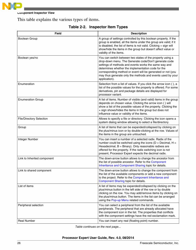
This table explains the various types of items.
Table 2-2. Inspector Item Types
Field Description
Boolean Group A group of settings controlled by this boolean property. If thegroup is enabled, all the items under the group are valid; if itis disabled, the list of items is not valid. Clicking + sign willshow/hide the items in the group but doesn't affect value orvalidity of the items.
Boolean yes/no You can switch between two states of the property using adrop-down menu. The Generate code/Don't generate codesettings of methods and events works the same way anddetermines whether the implementation code for thecorresponding method or event will be generated or not (youmay thus generate only the methods and events used by yourapplication).
Enumeration Selection from a list of values. If you click the arrow icon ( ), alist of the possible values for the property is offered. For somederivatives, pin and package details are displayed forprocessor variant.
Enumeration Group A list of items. Number of visible (and valid) items in the groupdepends on chosen value. Clicking the arrow icon ( ) willshow a list of the possible values of the property. Clicking the+ sign shows/hides the items in the group but does notinfluence value or validity of the items.
File/Directory Selection Allows to specify a file or directory. Clicking the icon opens asystem dialog window allowing to select a file/directory.
Group A list of items that can be expanded/collapsed by clicking onthe plus/minus icon or by double-clicking at the row. Values ofthe items in the group are untouched.
Integer Number You can insert a number of a selected radix. Radix of thenumber could be switched using the icons (D = Decimal, H =Hexadecimal, B = Binary). Only reasonable radixes areoffered for the property. If the radix switching icon is notpresent, Processor Expert expects the decimal radix.
Link to Inherited component The down-arrow button allows to change the ancestor fromthe list of possible ancestor. Refer to the ComponentInheritance and Component Sharing topic for details.
Link to shared component The down-arrow button allows to change the component fromthe list of the available components or add a new componentto the project. Refer to the Component Inheritance andComponent Sharing topic for details.
List of items A list of items may be expanded/collapsed by clicking on theplus/minus button in the left side of the row or by doubleclicking on the row. You may add/remove items by clicking onthe plus/minus button. The items in the list can be arrangedusing the Pop-up Menu related commands.
Peripheral selection You can select a peripheral from the list of the availableperipherals. The peripheral that are already allocated havethe component icon in the list. The properties that conflictswith the component settings have the red exclamation mark.
Real Number You can insert any real (floating point) number.
Table continues on the next page...
Component Inspector View
Processor Expert User Guide, Rev. 4.0, 08/2014
26 Freescale Semiconductor, Inc.
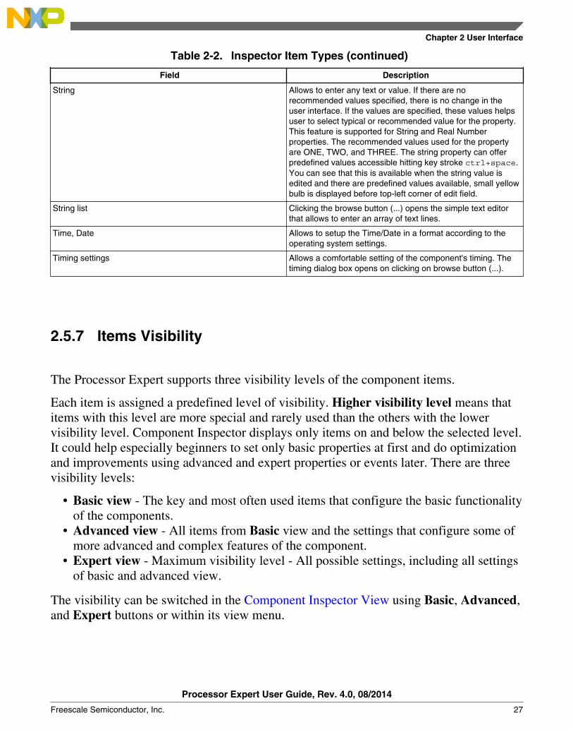
Table 2-2. Inspector Item Types (continued)
Field Description
String Allows to enter any text or value. If there are norecommended values specified, there is no change in theuser interface. If the values are specified, these values helpsuser to select typical or recommended value for the property.This feature is supported for String and Real Numberproperties. The recommended values used for the propertyare ONE, TWO, and THREE. The string property can offerpredefined values accessible hitting key stroke ctrl+space.You can see that this is available when the string value isedited and there are predefined values available, small yellowbulb is displayed before top-left corner of edit field.
String list Clicking the browse button (...) opens the simple text editorthat allows to enter an array of text lines.
Time, Date Allows to setup the Time/Date in a format according to theoperating system settings.
Timing settings Allows a comfortable setting of the component's timing. Thetiming dialog box opens on clicking on browse button (...).
2.5.7 Items Visibility
The Processor Expert supports three visibility levels of the component items.
Each item is assigned a predefined level of visibility. Higher visibility level means thatitems with this level are more special and rarely used than the others with the lowervisibility level. Component Inspector displays only items on and below the selected level.It could help especially beginners to set only basic properties at first and do optimizationand improvements using advanced and expert properties or events later. There are threevisibility levels:
• Basic view - The key and most often used items that configure the basic functionalityof the components.
• Advanced view - All items from Basic view and the settings that configure some ofmore advanced and complex features of the component.
• Expert view - Maximum visibility level - All possible settings, including all settingsof basic and advanced view.
The visibility can be switched in the Component Inspector View using Basic, Advanced,and Expert buttons or within its view menu.
Chapter 2 User Interface
Processor Expert User Guide, Rev. 4.0, 08/2014
Freescale Semiconductor, Inc. 27

NOTEIf an error occurs in a property with a higher visibility levelthan the level currently selected, then also this error isdisplayed.
2.5.8 Configuration Inspector
It is a variant of Component Inspector.
It displays the settings of a selected component. It could be invoked from configurationspop-up menu in the Components view (click on a configuration with the right-button andchoose the Configuration Inspector). For details on configurations, refer to theConfigurations topic.
2.5.8.1 Properties
The Properties tab of Component Inspector contains optimization settings related to theconfiguration.
These settings should be used when the code is already debugged. It could increase speedof the code, but the generated code is less protected for the unexpected situations andfinding errors could be more difficult.
Note that some of the options may not be present for all Processor Expert versions.
• Ignore range checking - This option can disable generation of the code thatprovides testing for parameter range. If the option is set to yes, methods do not returnerror code ERR_VALUE neither ERR_RANGE. If the method is called with incorrectparameter, it may not work correctly.
• Ignore enable test - This option can disable generation of the code that providestesting if the component/peripheral is internally enabled or not. If the option is set toyes, methods do not return error code ERR_DISABLED neither ERR_ENABLED. If the method iscalled in unsupported mode, it may not work correctly.
• Ignore speed mode test - This option can disable generation of the code, thatprovides a testing, if the component is internally supported in the selected speedmode. If the option is set to yes, methods do not return error code ERR_SPEED. If themethod is called in the speed mode when the component is not supported, it may notwork correctly.
Component Inspector View
Processor Expert User Guide, Rev. 4.0, 08/2014
28 Freescale Semiconductor, Inc.

• Use after reset values - This option allows Processor Expert to use the values ofperipheral registers which are declared by a chip manufacturer as default after resetvalues. If the option is set to no, all registers are initialized by a generated code, evenif the value after reset is the same as the required initialization value. If the option isset to yes, the register values same as the after reset values are not initialized.
• Complete initialization in Peripheral Init. Component - This option can disableshared initialization peripheral in Init methods of Peripheral InitializationComponents. If this option is set to yes, the complete peripheral initialization isprovided in Init method, even for parts that are already initialized in processor orelsewhere. It could mean longer code, but the initialization can be repeated inapplication using the Init method.
2.6 Processor View
It allows you to generate code from processor and also to switch the processor's package.To open this view, click Window > Show View > Other... and select Processor Expert> Processor.
Chapter 2 User Interface
Processor Expert User Guide, Rev. 4.0, 08/2014
Freescale Semiconductor, Inc. 29

Figure 2-11. Processor View
2.6.1 Control Buttons
The following table lists and describes the control buttons:
Table 2-3. Control Buttons
Buttons Description
Zoom in - Increases the detail level of the view. The wholepicture might not fit the viewing area.
Table continues on the next page...
Processor View
Processor Expert User Guide, Rev. 4.0, 08/2014
30 Freescale Semiconductor, Inc.
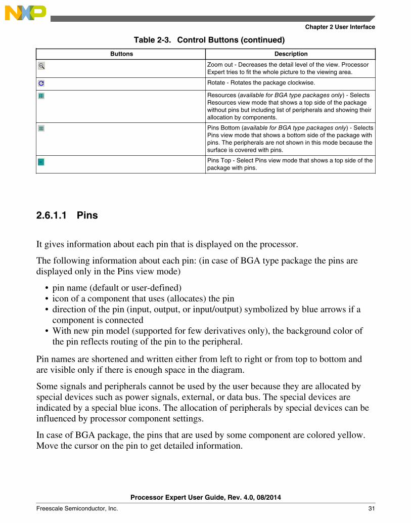
Table 2-3. Control Buttons (continued)
Buttons Description
Zoom out - Decreases the detail level of the view. ProcessorExpert tries to fit the whole picture to the viewing area.
Rotate - Rotates the package clockwise.
Resources (available for BGA type packages only) - SelectsResources view mode that shows a top side of the packagewithout pins but including list of peripherals and showing theirallocation by components.
Pins Bottom (available for BGA type packages only) - SelectsPins view mode that shows a bottom side of the package withpins. The peripherals are not shown in this mode because thesurface is covered with pins.
Pins Top - Select Pins view mode that shows a top side of thepackage with pins.
2.6.1.1 Pins
It gives information about each pin that is displayed on the processor.
The following information about each pin: (in case of BGA type package the pins aredisplayed only in the Pins view mode)
• pin name (default or user-defined)• icon of a component that uses (allocates) the pin• direction of the pin (input, output, or input/output) symbolized by blue arrows if a
component is connected• With new pin model (supported for few derivatives only), the background color of
the pin reflects routing of the pin to the peripheral.
Pin names are shortened and written either from left to right or from top to bottom andare visible only if there is enough space in the diagram.
Some signals and peripherals cannot be used by the user because they are allocated byspecial devices such as power signals, external, or data bus. The special devices areindicated by a special blue icons. The allocation of peripherals by special devices can beinfluenced by processor component settings.
In case of BGA package, the pins that are used by some component are colored yellow.Move the cursor on the pin to get detailed information.
Chapter 2 User Interface
Processor Expert User Guide, Rev. 4.0, 08/2014
Freescale Semiconductor, Inc. 31

2.6.1.2 Hints
It displays the basic information about the pin.
Pin hint contains:
• number of the pin (on package)• both names (default and user-defined)• owner of the pin (component that allocates it)• short pin description from processor database
Component icon hint contains:
• component name• component type• component description
2.6.1.3 Shared Pins
It explains how a pin is shared among peripherals.
If a pin is shared by multiple components, the line connecting the pin to the componenthas a red color. Refer to the Sharing Pins Among Peripherals topic for details.
2.6.1.4 On-chip Peripherals
The basic information about each on-chip peripheral is displayed on the processorpackage.
The following information is displayed on the processor package:
• peripheral device name (default or user-defined)• icon of the component that uses (allocates) the peripheral device
Peripheral device hint contains:
• peripheral device name• owner of the pin (component that allocates it)• short peripheral device description
Hint on icon contains:
Processor View
Processor Expert User Guide, Rev. 4.0, 08/2014
32 Freescale Semiconductor, Inc.
• component name• component type• component description
If a peripheral is shared by several components (for example, several components mayuse single pins of the same port), the icon is displayed.
NOTESome peripherals work in several modes and these peripheralscan be represented by a several devices in the processordatabases. For example, the device TimerX_PPG and TimerX_PWMrepresents TimerX in the PPG and PWM mode. These devicescan be displayed on the processor package, but they are alsorepresented as a single block in the microcontroller blockdiagram.
2.6.1.4.1 Peripheral or Pin Pop-up Menu
It displays peripheral or pin specific pop-up options.
The following options are available in the pop-up menu:
• Show Peripheral Initialization - Shows initialization values of all control, status,and data registers. This option is supported for all devices displayed on a processorpackage. Refer to the Configuration Registers View topic for details.
• Zoom in - Increases the detail level of the view. The whole picture might not fit theviewing area.
• Zoom out - Decreases the size of the picture and detail level of the view.• Rotate - Rotates the package by 90 degrees.• Add Component/Template - Adds a component or template for the appropriate
peripheral; all available components and templates suitable for the selectedperipheral are listed. The components and templates in the list are divided by ahorizontal line. It is possible to add only components or templates which areapplicable for the peripheral. It means that is possible to add the component ortemplate only if the peripheral is not already allocated to another component orcomponents. The components/templates that cannot be added to the peripheral aregrayed in the pop-up menu as unavailable. This option is supported for all devicesdisplayed on processor package.
• Remove Component - Allows to remove all components allocating peripheral inProcessor view. Processor component cannot be removed.
Chapter 2 User Interface
Processor Expert User Guide, Rev. 4.0, 08/2014
Freescale Semiconductor, Inc. 33
2.7 Memory Map ViewTo open this view, click Window > Show View > Other... and select Processor Expert>Memory Map.
Figure below shows the processor address space and internal and external memorymapping. Detailed information for an individual memory area is provided as a hint whenyou move the cursor over it.
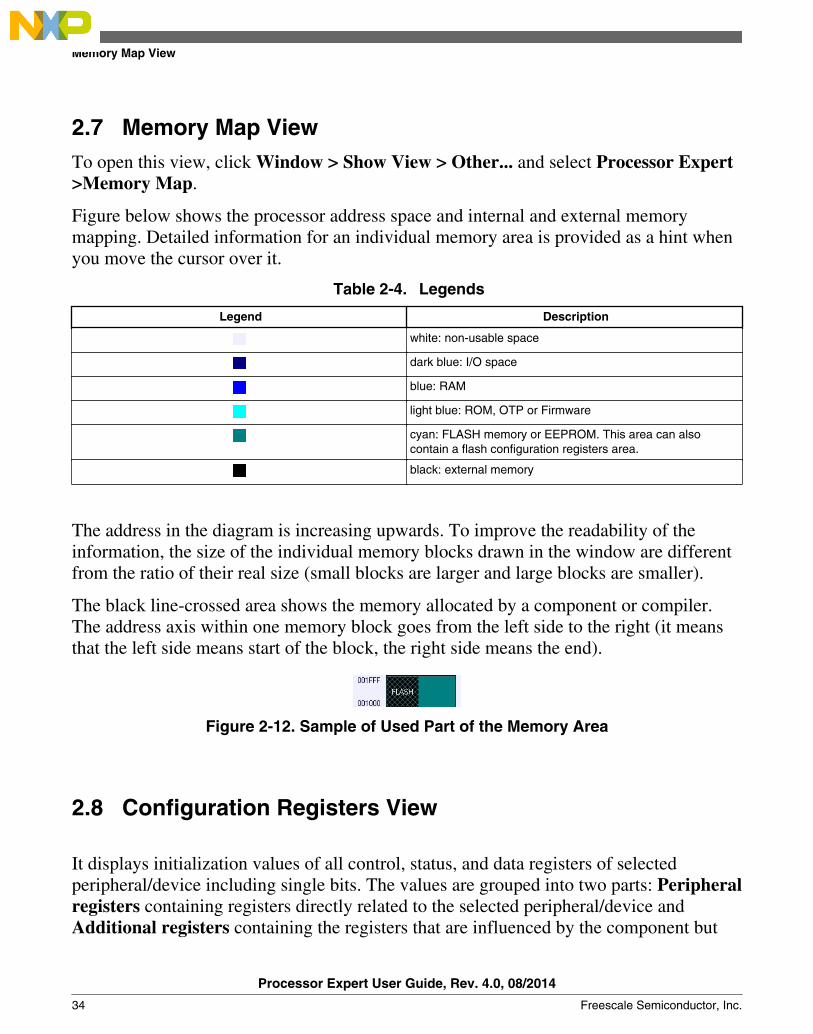
Table 2-4. Legends
Legend Description
white: non-usable space
dark blue: I/O space
blue: RAM
light blue: ROM, OTP or Firmware
cyan: FLASH memory or EEPROM. This area can alsocontain a flash configuration registers area.
black: external memory
The address in the diagram is increasing upwards. To improve the readability of theinformation, the size of the individual memory blocks drawn in the window are differentfrom the ratio of their real size (small blocks are larger and large blocks are smaller).
The black line-crossed area shows the memory allocated by a component or compiler.The address axis within one memory block goes from the left side to the right (it meansthat the left side means start of the block, the right side means the end).
Figure 2-12. Sample of Used Part of the Memory Area
2.8 Configuration Registers View
It displays initialization values of all control, status, and data registers of selectedperipheral/device including single bits. The values are grouped into two parts: Peripheralregisters containing registers directly related to the selected peripheral/device andAdditional registers containing the registers that are influenced by the component but
Memory Map View
Processor Expert User Guide, Rev. 4.0, 08/2014
34 Freescale Semiconductor, Inc.
are not listed for the peripheral currently selected in this view. To open this view, clickWindow > Show View > Other... and select Processor Expert > ConfigurationRegisters.
The initialization information reflects:
• Processor default settings - When the peripheral is not utilized by any EmbeddedComponent.
• Embedded Component settings - When the peripheral is utilized by an EmbeddedComponent and the component settings are correct. Peripheral Initialization Inspectorshows initialization as required by the component settings.
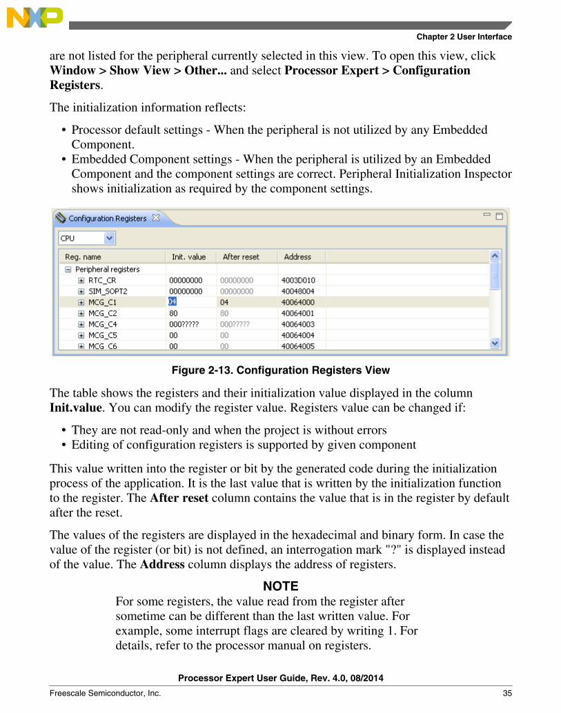
Figure 2-13. Configuration Registers View
The table shows the registers and their initialization value displayed in the columnInit.value. You can modify the register value. Registers value can be changed if:
• They are not read-only and when the project is without errors• Editing of configuration registers is supported by given component
This value written into the register or bit by the generated code during the initializationprocess of the application. It is the last value that is written by the initialization functionto the register. The After reset column contains the value that is in the register by defaultafter the reset.
The values of the registers are displayed in the hexadecimal and binary form. In case thevalue of the register (or bit) is not defined, an interrogation mark "?" is displayed insteadof the value. The Address column displays the address of registers.
NOTEFor some registers, the value read from the register aftersometime can be different than the last written value. Forexample, some interrupt flags are cleared by writing 1. Fordetails, refer to the processor manual on registers.
Chapter 2 User Interface
Processor Expert User Guide, Rev. 4.0, 08/2014
Freescale Semiconductor, Inc. 35

In case the peripheral is allocated by a component and the setting of the component isincorrect, the initialization values are not displayed in the Configuration Registers view.
Configuration Registers View
Processor Expert User Guide, Rev. 4.0, 08/2014
36 Freescale Semiconductor, Inc.
Chapter 3Using Processor Expert
It explains how to start using the Processor Expert tool and Embedded Components.
The Processor Expert menu is integrated as a plugin in the Eclipse IDE providing set ofviews.
This chapter explains:
• Create Projects• Basic Principles• Configuring Components• Component Inheritance and Component Sharing• Export and Import• Code Generation and Usage• Processor Expert Files and Directories
3.1 Create Project
To create a new project, select File > New > QorIQ Configuration Project from theEclipse IDE menu bar. Follow the steps in the New QorIQ Configuration Projectwizard that appears, and select a processor you want to use. For details on creating a newProcessor Expert project, refer to the QorIQ Configuration Suite Getting Started Guide.
The Processor Expert views can be opened any time using the menu command ProcessorExpert > ShowViews.
3.1.1 Select Components
Processor Expert User Guide, Rev. 4.0, 08/2014
Freescale Semiconductor, Inc. 37
The components to be used are selected in the Components Library view. You can addthe selected component into the project by right-clicking on it and selecting the Add toproject option from the pop-up menu. The component gets added to the EmbeddedComponents folder of the Components view.
For details on individual components, see tooltip which is displayed when cursor isplaced on the component or use the pop-up menu command Help on component.
3.1.2 Configure Components
The component to be configured is selected in the Components view. The componentgets opened in the Component Inspector, refer to the Component Inspector View section.For details on how to configure components, refer to the Configuring Components andalso refer to the user guide of each component.
3.1.3 Verify Settings
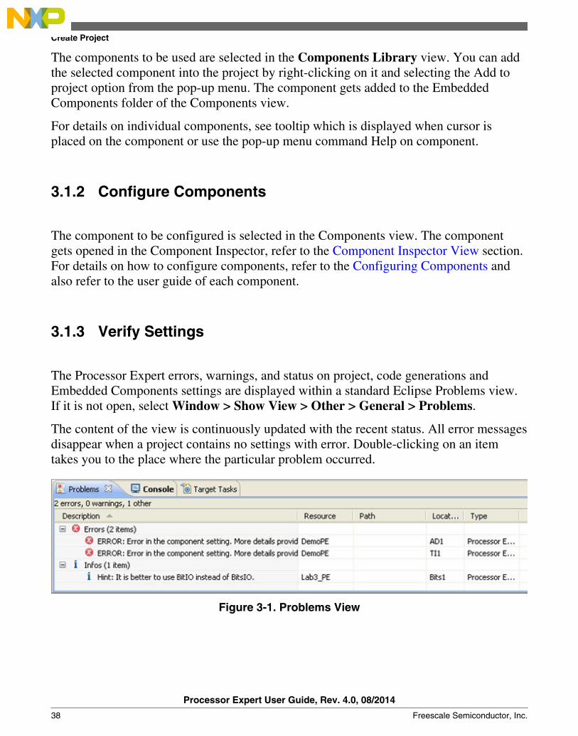
The Processor Expert errors, warnings, and status on project, code generations andEmbedded Components settings are displayed within a standard Eclipse Problems view.If it is not open, select Window > Show View > Other > General > Problems.
The content of the view is continuously updated with the recent status. All error messagesdisappear when a project contains no settings with error. Double-clicking on an itemtakes you to the place where the particular problem occurred.
Figure 3-1. Problems View
Create Project
Processor Expert User Guide, Rev. 4.0, 08/2014
38 Freescale Semiconductor, Inc.
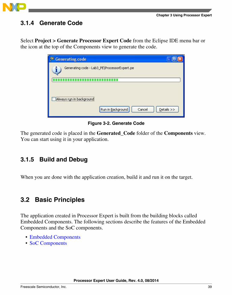
3.1.4 Generate Code
Select Project > Generate Processor Expert Code from the Eclipse IDE menu bar orthe icon at the top of the Components view to generate the code.
Figure 3-2. Generate Code
The generated code is placed in the Generated_Code folder of the Components view.You can start using it in your application.
3.1.5 Build and Debug
When you are done with the application creation, build it and run it on the target.
3.2 Basic Principles
The application created in Processor Expert is built from the building blocks calledEmbedded Components. The following sections describe the features of the EmbeddedComponents and the SoC components.
• Embedded Components• SoC Components
Chapter 3 Using Processor Expert
Processor Expert User Guide, Rev. 4.0, 08/2014
Freescale Semiconductor, Inc. 39

3.2.1 Embedded Components
Embedded Components encapsulate the initialization and functionality of embeddedsystems basic elements, such as processor core, on-chip peripherals, FPGAs, standaloneperipherals, virtual devices, and pure software algorithms. These facilities are displayedthrough properties, methods and events. It is very similar to objects in the ObjectOriented Programming (OOP) concept.
3.2.1.1 Easy Initialization
You can initialize components by setting their initialization properties in the ComponentInspector. Processor Expert generates the initialization code for the peripherals accordingto the properties of the appropriate components. You can decide whether the componentwill be initialized automatically at startup or manually by calling the component's Initmethod.
3.2.1.2 Easy On-chip Peripherals Management
Processor Expert knows exactly the relation between the allocated peripherals and theselected components. When you select a peripheral in the component properties,Processor Expert proposes all the possible candidates but signals the peripherals, whichare allocated already, using the icon of the component allocating the peripheral. ProcessorExpert also signalizes the peripherals that are not compatible with the current componentsettings with a red exclamation mark. In case of an unrealizable allocation, an error isgenerated. Unlike common libraries, Embedded Components are implemented for allpossible peripherals with optimal code. The most important advantages of the generatedmodules for driving peripherals are that you can:
• Select any peripheral that supports component function and change it whenever youwant during design time.
• Be sure that the component setting conforms to peripheral parameters.• Choose the initialization state of the component.• Choose which methods you want to use in your code and which event you want to
handle.• Use several components of the same type with optimal code for each component.
Basic Principles
Processor Expert User Guide, Rev. 4.0, 08/2014
40 Freescale Semiconductor, Inc.

The concept of the peripheral allocation generally does not enable sharing of peripheralsbecause it would make the application design too complicated. The only way to shareresources is through the components and their methods and events. For example, it ispossible to use the RTI shared component for sharing periodic interrupt from timers.
3.2.1.3 Component Categories
The complete list of the component categories and corresponding components can befound in the Categories tab of the Components Library view (refer to the ComponentsLibrary View section).
3.2.1.4 Levels of Abstraction
Processor Expert provides components with two several of abstraction and configurationcomfort.
• High Level Components - components that are the basic set of components designedcarefully to provide functionality to most microcontrollers in market. An applicationbuilt from these components can be easily ported to another microcontrollersupported by Processor Expert. This basic set contains, for example, components for
• simple I/O operations, such as BitIO, BitsIO, ByteIO, ...,• timers, such as EventCounter, TimerInt, FreeCntr, TimerOut, PWM, PPG,
Capture, WatchDog,• communication, such as AsynchroSerial, SynchroMaster, SynchroSlave,
AsynchroMaster, AsynchroSlave, IIC,• ADC,• internal memories. This group of components allows comfortable settings of a
desired functionality such as time in ms or frequency in Hz without letting youknow about the details of the hardware registers. The processor specific featuresare supported only as Processor specific settings or methods and are not portable.
• Low Level Components - components that are dependent on the peripheral structureto allow you to benefit from the non-standard features of a peripheral. The level ofportability is decreased due to a different component interface and the component isusually implemented only for a processor family offering the appropriate peripheral.However, you can easily set device features and use effective set of methods andevents.
• Peripheral Initialization Components - components that are on the lowest level ofabstraction. An interface of such components is based on the set of peripheral control
Chapter 3 Using Processor Expert
Processor Expert User Guide, Rev. 4.0, 08/2014
Freescale Semiconductor, Inc. 41
registers. These components cover all features of the peripherals and are designed forinitialization of these peripherals.
• Device Configuration - components that can produce various data, for example,configuration files, for configuring functional blocks of processors or operatingsystem.
NOTEThis version provides only Device Configuration components.
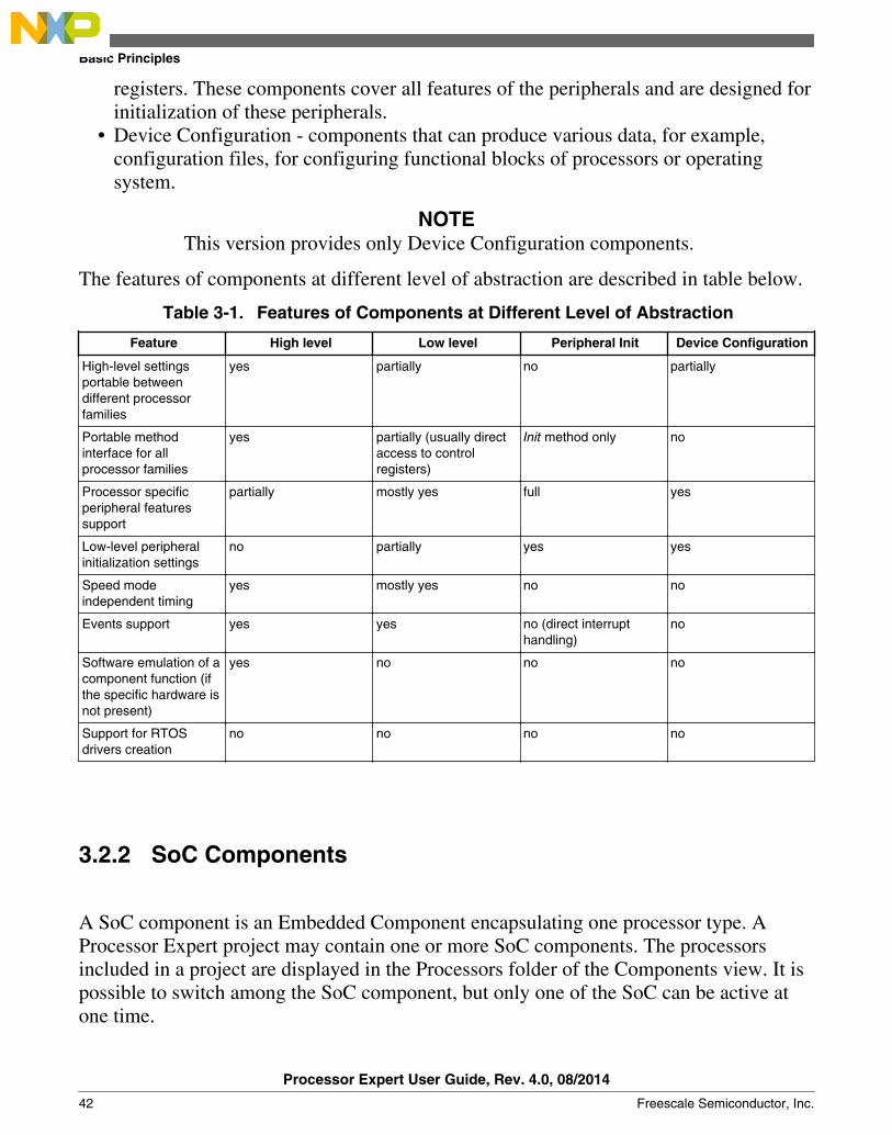
The features of components at different level of abstraction are described in table below.
Table 3-1. Features of Components at Different Level of Abstraction
Feature High level Low level Peripheral Init Device Configuration
High-level settingsportable betweendifferent processorfamilies
yes partially no partially
Portable methodinterface for allprocessor families
yes partially (usually directaccess to controlregisters)
Init method only no
Processor specificperipheral featuressupport
partially mostly yes full yes
Low-level peripheralinitialization settings
no partially yes yes
Speed modeindependent timing
yes mostly yes no no
Events support yes yes no (direct interrupthandling)
no
Software emulation of acomponent function (ifthe specific hardware isnot present)
yes no no no
Support for RTOSdrivers creation
no no no no
3.2.2 SoC Components
A SoC component is an Embedded Component encapsulating one processor type. AProcessor Expert project may contain one or more SoC components. The processorsincluded in a project are displayed in the Processors folder of the Components view. It ispossible to switch among the SoC component, but only one of the SoC can be active atone time.
Basic Principles
Processor Expert User Guide, Rev. 4.0, 08/2014
42 Freescale Semiconductor, Inc.

3.3 Configuring Components
Configuring the components in the project is one of the main activities in ProcessorExpert. It affects the initialization, run-time behavior and range of functionality availableto the user of the generated code.
The following sections describe how to configure the Embedded Components used in theproject correctly and effectively.
• Configurations• Design Time Checking• Creating User Component Templates• Signal Names
3.3.1 Configurations
Every configuration keeps the enable/disable state of all components in the project; itdoes not keep any component settings. If you enable/disable a component in the project,the component state is updated in the currently selected configuration. If you create a newconfiguration, the current project state is memorized.
The configurations of the current project are listed in the Configurations folder of theComponents view. The configurations can also hold additional settings that mayinfluence code generation and can be changed in the Configuration Inspector. Refer to theConfiguration Inspector section.
NOTEIt is possible to have two components with the same name inthe project. Each of the components could be enabled indifferent configuration. This way you can have different setupof a component (a component with the same name) in multipleconfigurations.
3.3.2 Design Time Checking
Chapter 3 Using Processor Expert
Processor Expert User Guide, Rev. 4.0, 08/2014
Freescale Semiconductor, Inc. 43

During project design time, Processor Expert performs instant checking of the project. Asa result of this checking, the error messages may appear in the Problems view or directlyin the third column of the Component Inspector. Sometimes it may happen that only onesmall change in the project causes error messages.
3.3.3 Creating User Component Templates
If you frequently use a component with some specific settings, you may need to save thecomponent with its settings as a template. This template is displayed in the ComponentsLibrary view, behaves as a normal component and could be added to any project. Thetemplate has the same properties as the original component. The values of the propertiesare preset in the template and could be marked as read only.
To create a component template and save it:
1. Open the pop-up menu of the required component in the Components view andselect the Save Component Settings as Template option. Alternatively, you can usethe Component Inspector view; open the view menu using the icon at the top rightcorner, and select Save Component Settings as Template.
2. In the Component Template dialog box, fill in the appropriate details of the template.
Figure 3-3. Save Template3. Click OK. The template appears in the Components Library view and can be
inserted into projects. Make sure that you refresh the Components Library view byselecting the Refresh option from pop-up menu.
Configuring Components
Processor Expert User Guide, Rev. 4.0, 08/2014
44 Freescale Semiconductor, Inc.

Figure 3-4. Components Library with Template Created
3.3.4 Signal Names
The main purpose of the signals is to allow you to name the pins used by componentswith names corresponding to the application.
A signal name can be assigned to an allocated pin by specifying the signal name into theappropriate property (for example, Pin_signal) in the component properties (available inAdvanced view mode). A signal name is an identifier that must start with a letter and restof the name must contain only letters, numbers, and underscore characters.
For the components that allocate a whole port, such as ByteIO, there are two options:
• Assign a same signal name to all pins of port by writing the name into the Port signalproperty. Processor Expert automatically assigns this name extended with a bitnumber suffix to each of the individual pins.
• Assign a different signal name to individual pins by writing pin signal names (fromthe lowest bit to the highest one) separated by commas or spaces into the Port signalproperty.
Figure 3-5. Signal Name List for a Port
Chapter 3 Using Processor Expert
Processor Expert User Guide, Rev. 4.0, 08/2014
Freescale Semiconductor, Inc. 45

3.3.4.1 Documentation
Processor Expert automatically generates a document ProcessorExpert_SIGNALS.txtcontaining a list of relationship between defined signals and corresponding pins. There isan additional signal direction information added next to each signal name and pin numberinformation next to each pin name.
This document is available in the Documentation folder of the Components view. Asample of generated signals documentation is shown below.
Figure 3-6. Document Containing Signals Details
3.4 Component Inheritance and Component Sharing
Component Inheritance and Component Sharing
Processor Expert User Guide, Rev. 4.0, 08/2014
46 Freescale Semiconductor, Inc.
• Ancestor is a component that is inherited (used) by another component.• Descendant is a new component that inherits (uses) another component(s).• Shared Ancestor is a component that can be used and shared by multiple
components.
3.4.1 Inheritance
Inheritance in Processor Expert means that an ancestor component is used only by thedescendant component. Inheritance is supported in order to allow components to accessperipherals by hardware-independent interface of the ancestor components. For example,a component that emulates a simple I2C transmitter may inherit two BitIO componentsfor generation of an output signal.
On several complex components inheritance is used to separate component settings intoseveral logical parts, for example, settings of channel is inherited in the component withsettings of the main peripheral module.
3.4.2 Settings in Processor Expert
The Descendant component contains a property that allows selecting an ancestorcomponent from a predefined list of templates. The component is created after selectionof an appropriate template name (or component name) from the list of the templatesfitting the specified interface. Any previously used ancestor component is discarded.
Figure 3-7. Inherited Component Item in Inspector
Processor Expert allows you to select from ancestors that implement the requiredinterface and are registered by the descendant component.
The ancestor component is displayed under its descendant in the project structure tree inthe Components view.
Figure 3-8. Example of Ancestor and Descendant Components in the Components view
Chapter 3 Using Processor Expert
Processor Expert User Guide, Rev. 4.0, 08/2014
Freescale Semiconductor, Inc. 47
An ancestor component requires a list of methods and events ( interface ), which must beimplemented by an ancestor component. The error is shown if the ancestor componentdoes not implement any of them. For example, if the settings of the descendantcomponent do not allow it to generate this method.
3.4.3 Component Sharing
Component sharing allows you to cause several components to use capability of onecomponent similar to inheritance. This feature allows sharing of its resources and itsdrivers with other components. For example, components may share an I2C componentfor communication with peripherals connected to the I2C bus or some component may doDMA transfers using DMA component.
3.4.4 Settings in Processor Expert
A shared ancestor component contains a property that allows you to select existing sharedancestor component or create a new one. In this case, the ancestor component is includedin the project tree as the other components. The ancestor component may be used withthe descendant component only if it is created from a template registered in thedescendant component or if the component type is registered in the descendantcomponent. It is recommended that you always create a shared ancestor componentthrough a descendant component.
Figure 3-9. Popup Menu for Selection/Creation of a Shared Ancestor Component
3.4.5 Run-time Resources Allocation
Processor Expert (generated code) does not check the usage of shared resources/code. It'sup to you to ensure the correct run-time resources allocation of a shared ancestorcomponent. Often, it is not possible for a shared ancestor component to be usedsimultaneously by several components.
Component Inheritance and Component Sharing
Processor Expert User Guide, Rev. 4.0, 08/2014
48 Freescale Semiconductor, Inc.
3.5 Sharing Pins Among Peripherals
Explains that some of the Processors allow few pins to be used or shared by multipleperipherals.
This may lead to the need of sharing pin(s) by multiple components. Normally, if youselect one pin in more than one component, a conflict is reported. However, it is possibleto setup a sharing for such pin in the component inspector.
One of the components sharing a pin has to be chosen as a main component. Thiscomponent will initialize the pin. In the properties of other components that use the pin,the pin has to be marked as shared (see figure below).
Pin sharing can be set in the Component Inspector. The Component Inspector must bein EXPERT view mode. Use the pop-up menu of the property and select the commandPin Sharing Enabled.
Figure 3-10. Pin Property with Sharing Enabled
Pin sharing is advanced usage of the processor peripherals and should be done only byskilled users. Pin sharing allows advanced usage of the pins even on small processorpackages and allows application-specific usage of the pins.
3.5.1 ConnectPin Method
It is necessary to invoke the component method ConnectPin to connect a component to theshared pin. It is also necessary to invoke the main component method to connect pin backto the main component. In fact, the peripherals can usually operate simultaneously, butthey have no connection to the shared pins unless the ConnectPin method is executed. Incase that all components control the shared pin using one peripheral, it is not necessary touse the ConnectPin method.
Shared pins are presented in the Processor View as well. The component to pinconnection line is red.
Chapter 3 Using Processor Expert
Processor Expert User Guide, Rev. 4.0, 08/2014
Freescale Semiconductor, Inc. 49

3.6 Export and Import
This topic explains:
• Export Component Settings• Export Board Configuration• Import Component Settings• Apply Board Configuration• Import Component(s) from Package
3.6.1 Export Component Settings
It is possible to export one or more component settings, such as:
• Configurations• Operating system• Processors• Components
To export component settings:
1. In the IDE, select File > Export. The Export wizard appears.
Expand Processor Expert tree. Select Export Component Settings option as shownbelow.
Export and Import
Processor Expert User Guide, Rev. 4.0, 08/2014
50 Freescale Semiconductor, Inc.
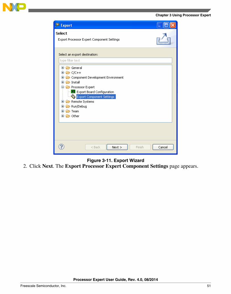
Figure 3-11. Export Wizard2. Click Next. The Export Processor Expert Component Settings page appears.
Chapter 3 Using Processor Expert
Processor Expert User Guide, Rev. 4.0, 08/2014
Freescale Semiconductor, Inc. 51
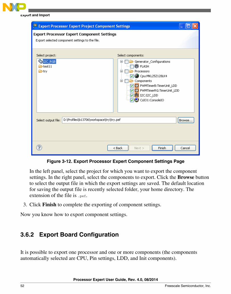
Figure 3-12. Export Processor Expert Component Settings Page
In the left panel, select the project for which you want to export the componentsettings. In the right panel, select the components to export. Click the Browse buttonto select the output file in which the export settings are saved. The default locationfor saving the output file is recently selected folder, your home directory. Theextension of the file is .pef.
3. Click Finish to complete the exporting of component settings.
Now you know how to export component settings.
3.6.2 Export Board Configuration
It is possible to export one processor and one or more components (the componentsautomatically selected are CPU, Pin settings, LDD, and Init components).
Export and Import
Processor Expert User Guide, Rev. 4.0, 08/2014
52 Freescale Semiconductor, Inc.

You can save the current state of components related to board configuration in to theexternal file. The extension of the file is .peb. The default location for saving the outputfile is recently selected folder, your home directory.
To export board configuration:
1. In the IDE, select File > Export. The Export wizard appears.
Expand Processor Expert tree. Select Export Board Configuration option asshown below.
Figure 3-13. Export Wizard2. Click Next. The Expert Processor Expert Board Configuration page appears.
Chapter 3 Using Processor Expert
Processor Expert User Guide, Rev. 4.0, 08/2014
Freescale Semiconductor, Inc. 53
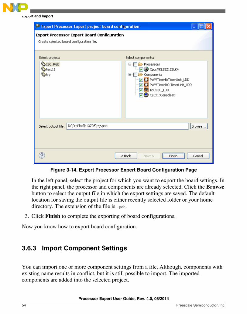
Figure 3-14. Expert Processor Expert Board Configuration Page
In the left panel, select the project for which you want to export the board settings. Inthe right panel, the processor and components are already selected. Click the Browsebutton to select the output file in which the export settings are saved. The defaultlocation for saving the output file is either recently selected folder or your homedirectory. The extension of the file is .peb.
3. Click Finish to complete the exporting of board configurations.
Now you know how to export board configuration.
3.6.3 Import Component Settings
You can import one or more component settings from a file. Although, components withexisting name results in conflict, but it is still possible to import. The importedcomponents are added into the selected project.
Export and Import
Processor Expert User Guide, Rev. 4.0, 08/2014
54 Freescale Semiconductor, Inc.

To import component settings:
1. In the IDE, select File > Import. The Import wizard appears.
Expand Processor Expert tree. Select Import Component Settings option asshown below.
Figure 3-15. Import Wizard2. Click Next. The Import Component Settings page appears.
Chapter 3 Using Processor Expert
Processor Expert User Guide, Rev. 4.0, 08/2014
Freescale Semiconductor, Inc. 55

Figure 3-16. Import Component Settings Page
To import component settings from the file to selected project, click the Browsebutton. Select the input file with the pefor .peb or .peextension. The default optionReplace settings is selected if imported component settings are having same name(or ID) and type.
You can select the mode for importing components settings, the options are:
• Ignore - do not import this component settings• Add new - add new component with imported settings• Add new, keep existing - if component with same name or type exists, it will add a
new component with imported settings and keep the existing one (may causeconflicts)
• Add new, disable existing - if component with same name or type exists, it will adda new component with imported settings and disable the existing one
• Replace settings - replace existing component with new settings from imported file• Click Finish. The settings from the .pef file is imported to the selected project.
Export and Import
Processor Expert User Guide, Rev. 4.0, 08/2014
56 Freescale Semiconductor, Inc.
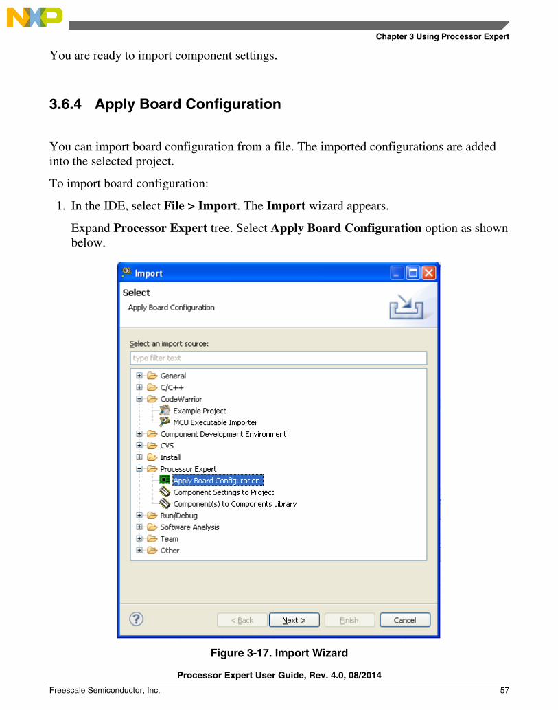
You are ready to import component settings.
3.6.4 Apply Board Configuration
You can import board configuration from a file. The imported configurations are addedinto the selected project.
To import board configuration:
1. In the IDE, select File > Import. The Import wizard appears.
Expand Processor Expert tree. Select Apply Board Configuration option as shownbelow.
Figure 3-17. Import Wizard
Chapter 3 Using Processor Expert
Processor Expert User Guide, Rev. 4.0, 08/2014
Freescale Semiconductor, Inc. 57
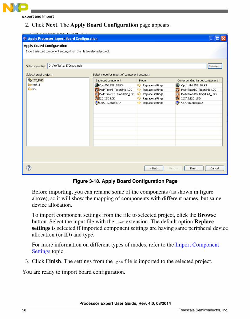
2. Click Next. The Apply Board Configuration page appears.
Figure 3-18. Apply Board Configuration Page
Before importing, you can rename some of the components (as shown in figureabove), so it will show the mapping of components with different names, but samedevice allocation.
To import component settings from the file to selected project, click the Browsebutton. Select the input file with the .peb extension. The default option Replacesettings is selected if imported component settings are having same peripheral deviceallocation (or ID) and type.
For more information on different types of modes, refer to the Import ComponentSettings topic.
3. Click Finish. The settings from the .peb file is imported to the selected project.
You are ready to import board configuration.
Export and Import
Processor Expert User Guide, Rev. 4.0, 08/2014
58 Freescale Semiconductor, Inc.
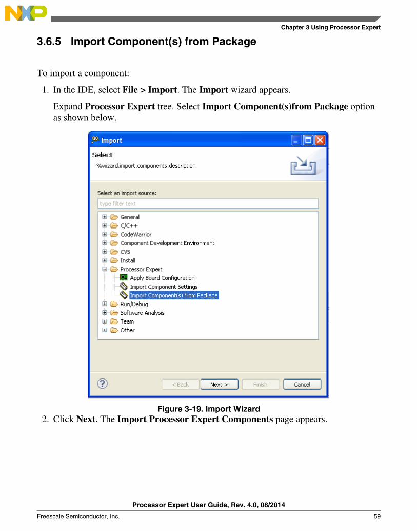
3.6.5 Import Component(s) from Package
To import a component:
1. In the IDE, select File > Import. The Import wizard appears.
Expand Processor Expert tree. Select Import Component(s)from Package optionas shown below.
Figure 3-19. Import Wizard2. Click Next. The Import Processor Expert Components page appears.
Chapter 3 Using Processor Expert
Processor Expert User Guide, Rev. 4.0, 08/2014
Freescale Semiconductor, Inc. 59

Figure 3-20. Import Processor Expert Components Page3. Click Finish to select and install Processor Expert update packages (.PEUpd) files.
3.7 Code Generation and Usage
It explains you about the principles and results of the Processor Expert code generationprocess and the correct ways and possibilities of using this code in the user application.
In the Project Explorer view, select ProcessorExpert.pe and right-click to selectGenerate Processor Expert Code Generate Code option to initiate the code generationprocess. During this process output files of the components contained in the project aregenerated. The project must be set-up correctly for successful code generation. If thegeneration is error free all generated source code files are saved to the destinationdirectory.
3.7.1 Files Produced by Processor Expert
Code Generation and Usage
Processor Expert User Guide, Rev. 4.0, 08/2014
60 Freescale Semiconductor, Inc.

The existence of the files can be conditional to project or Processor Expert environmentsettings and their usage by the components.
• Component files
Component output files. Refer to the individual component user guides for detailsabout generated output.
• Signal names
This is a simple text file {projectname}_SIGNALS.txt or {projectname}_SIGNALS.doc with alist of all used signal names. The signal name can be assigned to an allocated pin inthe component properties (available in Advanced view mode). This documentationcan be found in the Documentation folder of the Components view. Refer to theSignal Names topic for details.
• Code generation log that contains information on changes since last codegeneration.
• XML documentation containing the project information and settings of allcomponents in XML format. The generated file {projectname}_Settings.xml can befound in the Documentation folder of the Components view. It is updated after eachsuccessful code generation.
3.7.2 Tracking Changes in Generated Code
Processor Expert allows to track changes in generated modules. It is necessary to enablethe option Create code generation log in the Processor Expert Project Options dialog box.Refer to the Processor Expert Options topic for details. If this option is enabled, a fileProcessorExpert_CodeGeneration.txt is generated into Documentation folder.
The file contains a list of changes with details on purpose of each change. Refer to theexample below:
Listing 3-1. Example - Tracking Changes in Generated Code
###############################################################Code generation 2010/10/22, 15:57; CodeGen: 1 by user:
by Processor Expert 5.00 for Freescale Microcontrollers; PE core 04.46
Configuration: Debug_S08GW64CLH
Target CPU: MC9S08GW64_64; CPUDB ver 3.00.000
# The following code generation options were changed:
> option Create code generation log: value changed from false to true
Chapter 3 Using Processor Expert
Processor Expert User Guide, Rev. 4.0, 08/2014
Freescale Semiconductor, Inc. 61
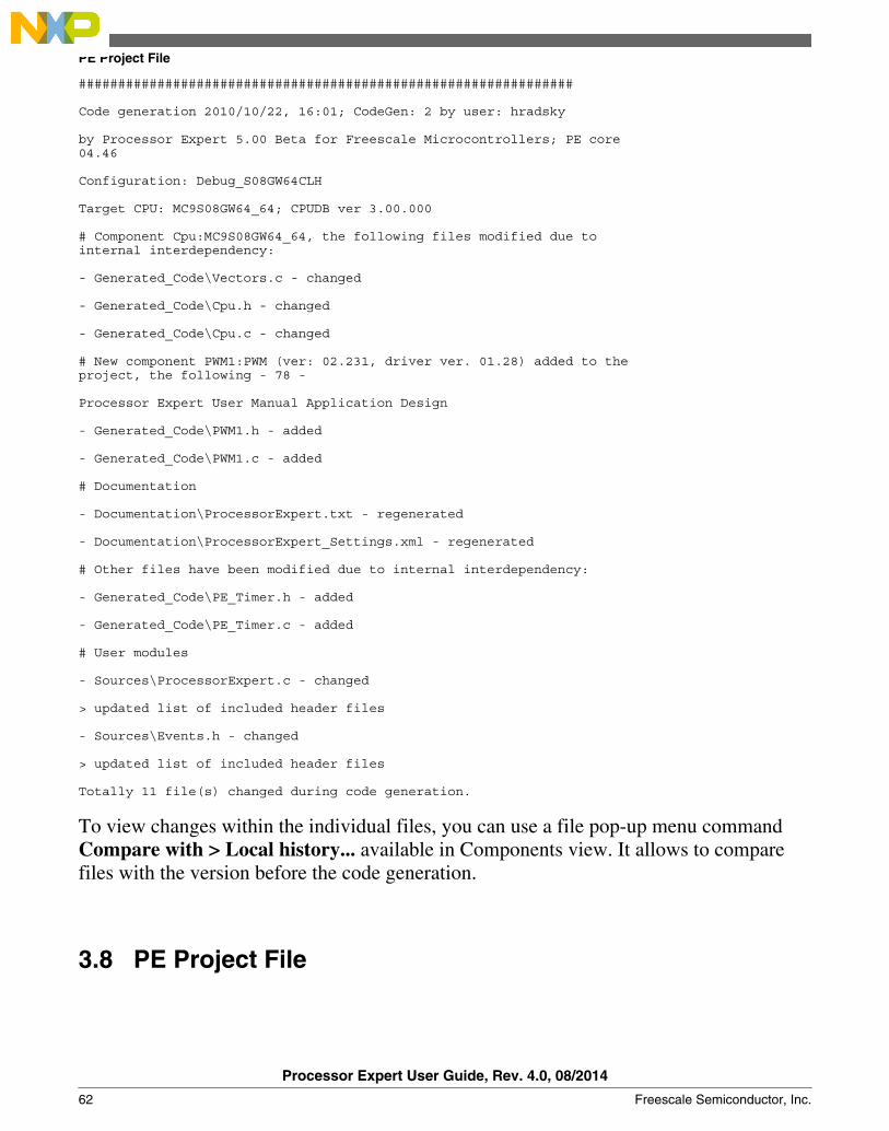
###############################################################
Code generation 2010/10/22, 16:01; CodeGen: 2 by user: hradsky
by Processor Expert 5.00 Beta for Freescale Microcontrollers; PE core 04.46
Configuration: Debug_S08GW64CLH
Target CPU: MC9S08GW64_64; CPUDB ver 3.00.000
# Component Cpu:MC9S08GW64_64, the following files modified due to internal interdependency:
- Generated_Code\Vectors.c - changed
- Generated_Code\Cpu.h - changed
- Generated_Code\Cpu.c - changed
# New component PWM1:PWM (ver: 02.231, driver ver. 01.28) added to the project, the following - 78 -
Processor Expert User Manual Application Design
- Generated_Code\PWM1.h - added
- Generated_Code\PWM1.c - added
# Documentation
- Documentation\ProcessorExpert.txt - regenerated
- Documentation\ProcessorExpert_Settings.xml - regenerated
# Other files have been modified due to internal interdependency:
- Generated_Code\PE_Timer.h - added
- Generated_Code\PE_Timer.c - added
# User modules
- Sources\ProcessorExpert.c - changed
> updated list of included header files
- Sources\Events.h - changed
> updated list of included header files
Totally 11 file(s) changed during code generation.
To view changes within the individual files, you can use a file pop-up menu commandCompare with > Local history... available in Components view. It allows to comparefiles with the version before the code generation.
3.8 PE Project File
PE Project File
Processor Expert User Guide, Rev. 4.0, 08/2014
62 Freescale Semiconductor, Inc.

All components in the project with their state and settings and all configurations arestored in one file ProcessorExpert.pe in the root of project directory. If the wholecontent of the project including subdirectories is copied or moved to another directory, itis still possible to open and use it in the new location.
3.8.1 Project Directory Structure
Processor Expert uses the following sub-directory structure within the project directory:
• \ Generated_Code - the directory containing all generated source code modules forcomponents.
• \ Documentation - the directory with the project documentation files generated byProcessor Expert.
• \ Sources - the directory for main module, event module other user modules.
User-created templates are shared by all users and are stored in the following folder:
• On Windows - %ALLUSERSPROFILE%\ApplicationData\Processor Expert\{version}\
For example, C:\Documents and Settings\All Users\ApplicationData\ProcessorExpert\CW08_PE3_02\
• On Linux - {workspace}/.metadata/.plugins/com.freescale.processorexpert.core/ProcessorExpert/{version}
The path is relative to the current Eclipse workspace directory.
Chapter 3 Using Processor Expert
Processor Expert User Guide, Rev. 4.0, 08/2014
Freescale Semiconductor, Inc. 63

PE Project File
Processor Expert User Guide, Rev. 4.0, 08/2014
64 Freescale Semiconductor, Inc.
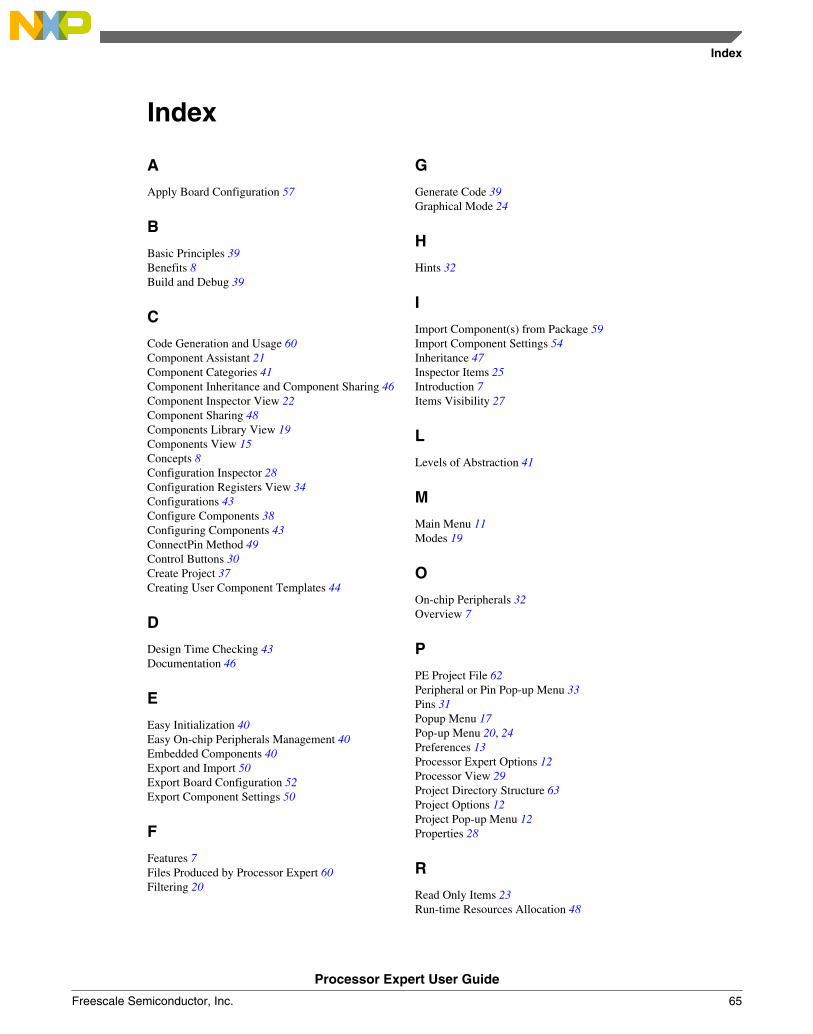
Index
A
Apply Board Configuration 57
B
Basic Principles 39Benefits 8Build and Debug 39
C
Code Generation and Usage 60Component Assistant 21Component Categories 41Component Inheritance and Component Sharing 46Component Inspector View 22Component Sharing 48Components Library View 19Components View 15Concepts 8Configuration Inspector 28Configuration Registers View 34Configurations 43Configure Components 38Configuring Components 43ConnectPin Method 49Control Buttons 30Create Project 37Creating User Component Templates 44
D
Design Time Checking 43Documentation 46
E
Easy Initialization 40Easy On-chip Peripherals Management 40Embedded Components 40Export and Import 50Export Board Configuration 52Export Component Settings 50
F
Features 7Files Produced by Processor Expert 60Filtering 20
G
Generate Code 39Graphical Mode 24
H
Hints 32
I
Import Component(s) from Package 59Import Component Settings 54Inheritance 47Inspector Items 25Introduction 7Items Visibility 27
L
Levels of Abstraction 41
M
Main Menu 11Modes 19
O
On-chip Peripherals 32Overview 7
P
PE Project File 62Peripheral or Pin Pop-up Menu 33Pins 31Popup Menu 17Pop-up Menu 20, 24Preferences 13Processor Expert Options 12Processor View 29Project Directory Structure 63Project Options 12Project Pop-up Menu 12Properties 28
R
Read Only Items 23Run-time Resources Allocation 48
Index
Processor Expert User Guide
Freescale Semiconductor, Inc. 65
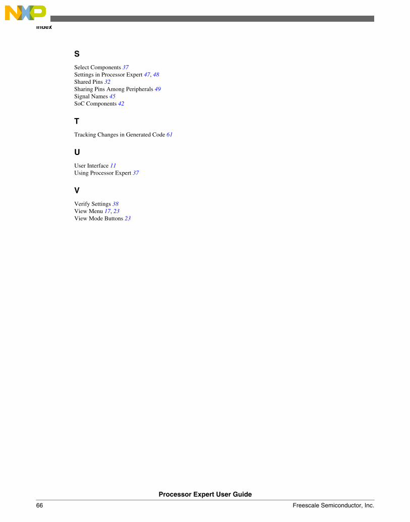
S
Select Components 37Settings in Processor Expert 47, 48Shared Pins 32Sharing Pins Among Peripherals 49Signal Names 45SoC Components 42
T
Tracking Changes in Generated Code 61
U
User Interface 11Using Processor Expert 37
V
Verify Settings 38View Menu 17, 23View Mode Buttons 23
Index
Processor Expert User Guide
66 Freescale Semiconductor, Inc.

How to Reach Us:
Home Page:freescale.com
Web Support:freescale.com/support
Information in this document is provided solely to enable system and
software implementers to use Freescale products. There are no express
or implied copyright licenses granted hereunder to design or fabricate
any integrated circuits based on the information in this document.
Freescale reserves the right to make changes without further notice to
any products herein. Freescale makes no warranty, representation, or
guarantee regarding the suitability of its products for any particular
purpose, nor does Freescale assume any liability arising out of the
application or use of any product or circuit, and specifically disclaims
any and all liability, including without limitation consequential or
incidental damages. “Typical” parameters that may be provided in
Freescale data sheets and/or specifications can and do vary in different
applications, and actual performance may vary over time. All operating
parameters, including “typicals,” must be validated for each customer
application by customer's technical experts. Freescale does not convey
any license under its patent rights nor the rights of others. Freescale
sells products pursuant to standard terms and conditions of sale, which
can be found at the following address: freescale.com/
SalesTermsandConditions.
Freescale, the Freescale logo, AltiVec, C-5, CodeTest, CodeWarrior,
ColdFire, ColdFire+, C-Ware, Energy Efficient Solutions logo, Kinetis,
mobileGT, PowerQUICC, Processor Expert, QorIQ, Qorivva, StarCore,
Symphony, and VortiQa are trademarks of Freescale Semiconductor,
Inc., Reg. U.S. Pat. & Tm. Off. Airfast, BeeKit, BeeStack, CoreNet,
Flexis, Layerscape, MagniV, MXC, Platform in a Package, QorIQ
Qonverge, QUICC Engine, Ready Play, SafeAssure, SafeAssure logo,
SMARTMOS, Tower, TurboLink, Vybrid, and Xtrinsic are trademarks of
Freescale Semiconductor, Inc. All other product or service names are
the property of their respective owners.
© 2011–2014 Freescale Semiconductor, Inc.
Document Number QCSPEXUGRevision 4.0, 08/2014