procurement of 550 automatic weather ...imdpune.gov.in/aws/rfp_550aws_tdma_ers_july2007.pdfrequest...
TRANSCRIPT
REQUEST FOR PROPOSAL (RFP) DOCUMENT
FOR
PROCUREMENT OF 550 AUTOMATIC WEATHER STATIONS (AWS) AND ONE TDMA TYPE
RECEIVING EARTH STATION
JULY 2007
Government of India
India Meteorological Department
Office of Dy. Director General of Meteorology (Surface Instruments)
Pune - 411 005.
2
CONTENTS
1. INTRODUCTION ....................................................................................................................................... 4
2. SCOPE OF PRESENT TENDER ENQUIRY ........................................................................................ 4
3. OVERALL REQUIREMENTS OF AWS SYSTEMS TO BE SUPPLIED .......................................... 4
4 SPECIFICATIONS OF SENSORS ......................................................................................................... 5
4.1 General Specifications: .......................................................................................................... 5
4.2 Individual Sensor Specifications ........................................................................................... 6
5. SPECIFICATIONS OF DATA LOGGER AND TRANSMISSION SYSTEM .................................... 9
5.1 Datalogger specifications ....................................................................................................... 9
5.2 AWS Transmitter & Antenna ................................................................................................ 11
5.3 Certification ............................................................................................................................ 13
5.4 Requirements for Optional Display Unit ............................................................................. 13
6. TIME DIVISION MULTIPLE ACCESS (TDMA) SCHEME ............................................................... 14
7. AWS SITE PREPARATION .................................................................................................................. 16
8 SPECIFICATIONS OF EARTH STATION EQUIPMENTS ............................................................... 17
8.1 General features .................................................................................................................... 17
8.2 Hardware features ................................................................................................................. 18
8.3 Details of earth station antenna ........................................................................................... 19
8.4 Features of LNA .................................................................................................................... 19
8.5 Features of Synthesized Down converter ......................................................................... 20
8.6 Features of Digital Receiver / BPSK Demodulator ............................................................. 20
8.7 Signal diagnostic features .................................................................................................... 21
8.8 Specifications of data processing computer ..................................................................... 22
8.8.1 AWS Data Processing ............................................................................................................. 23
8.8.2 General features ...................................................................................................................... 23
8.8.3 Archival .................................................................................................................................... 26
8.8.4 Software deliverables .............................................................................................................. 26
9. TELEMETRY LINK CALCULATIONS................................................................................................. 27
10. TRAINING TO IMD OFFICIALS ........................................................................................................... 29
11. WARRANTY AND MAINTENANCE .................................................................................................... 29
3
12. TESTING, INSTALLATION & CALIBRATION KIT ........................................................................... 29
13. DOCUMENTATION ............................................................................................................................... 30
14. COMPLIANCE / NON-COMPLIANCE STATEMENT ....................................................................... 30
15. RELIABILITY .......................................................................................................................................... 30
16. SPARES AND CONSUMABLES ......................................................................................................... 30
17. INSTALLATION, SYSTEM INTEGRATION AND COMMISSIONING ........................................... 30
18. DELIVERY SCHEDULE ......................................................................................................................... 31
19. PRICE PROPOSAL ................................................................................................................................ 31
20. TESTING AND ACCEPTANCE ............................................................................................................ 32
21. SITE PREPARATION............................................................................................................................. 32
22. SYSTEM DESIGN REVIEW .................................................................................................................. 32
Annexure - I ........................................................................................................................................................ 33
Annexure – II ...................................................................................................................................................... 34
Annexure – III ...................................................................................................................................................... 39
Annexure IV ....................................................................................................................................................... 40
Annexure V ........................................................................................................................................................... 43
4
SPECIFICATIONS FOR PROCUREMENT OF 550 AUTOMATIC WEATHER STATIONS AND ONE TDMA
TYPE RECEIVING EARTH STATION
(REQUEST FOR PROPOSAL (RFP) DOCUMENT)
1. INTRODUCTION
As part of augmentation of Surface Meteorological Network of IMD, it is proposed to install 550 more AWS (which includes 127 agromet stations and 50 AWS exclusively for North Eastern region) in different parts of India. These systems should be compatible with the existing Earth Receiving System and INSAT / KALPANA-1 Data Relay Transponder (DRT) as well as the DRT of future INSAT systems (INSAT-3D etc.).
2. SCOPE OF PRESENT TENDER ENQUIRY
Following is the scope of this tender document to implement the new project for installation and commissioning of 550 AWS at selected field stations all over India on a turnkey basis:
Supply of AWS equipment consisting of sensors, data logger (with built in display) and transmission system incorporating GPS facility and optional slave display unit for display of meteorological parameters.
Preparation of AWS field sites as per specifications (Annexure-II).
Transportation of equipment from Pune, installation and commissioning of AWS at field sites all over India. Details of 550 stations as shown in Annexure-III will be finalized and provided at the time of design review committee meeting to the successful bidder.
Uplinking AWS data to the satellite compatible with INSAT-3A, KALPANA-1 and INSAT-3D DRTs. Details of satellites are provided in Annexure-I
Procurement and installation of AWS data receiving earth station hardware and software compatible for TDMA type of data format.
Procurement of necessary spare AWS systems complete in all respects.
Configuration, Installation and Commissioning of 127 Agro-AWS with sensors for agrometeorological use as per international norms.
3. OVERALL REQUIREMENTS OF AWS SYSTEMS TO BE SUPPLIED 3.1 The AWS equipment should incorporate the state-of-the-art technology (e.g. micro
controller, ASIC, FPGA etc) and provide capability for unattended operation for at least one year at remote places using a 12V single sealed maintenance-free battery, rechargeable through a solar panel. All equipment should be qualified for MIL STD –
5
454K Specifications and suitable for outdoor applications. The AWS must be housed in weather-proof enclosure and shall meet all specified environmental specifications.
3.2 Transmitter and data logger must have certification from IMD for functional operation
through INSAT / Kalpana satellites. 3.3 The chassis/enclosure should withstand hostile environment and its moulding should
be completely sealed by suitable gasketing to avoid penetration of moisture, salinity etc.
3.4 AWS system should have in-built memory of storing data for at least 12 months
period. 3.5 PCMCIA memory card slot or any other commercially available latest technology
memory device for data retrieval and transfer of set up of the system. All set up and configuration files should be transferable through the solid state memory device to the data logger and vice versa.
3.6 The system should have inbuilt test facility to monitor and display the configuration
and functions of various subsystems including present and past data.
3.7 Antenna should be portable with LHCP and RHCP modes of polarization (switchable in the field) compatible with INSAT-3A/KALPANA-1/INSAT-3D DRTs.
3.8 Test points to be provided on the system for monitoring the clock and data bit stream and facility to view the above on the front panel display.
3.9 Two RS-232, one RS-485 and one USB port are to be provided. The ports are to be used for programming and data retrieval, thus making the system fully compatible with a Personal Computer (PC) / Laptop, as and when required.
3.10 System should have a dedicated port to interface a remote display unit and facilitate values of meteorological parameters to be displayed in real time basis at user-defined intervals. The location of the display unit may vary from 50 metres to 2 km from site to site.
3.11 Facility to give manual commands to transmit data for testing purpose.
3.12 Provision of extra five channels for manual data entry of conventional observations like cloud, visibility etc.
3.13 Facility for entering manually recorded Synoptic weather observation for manual and/or auto transmission through front panel keypad.
3.14 Facility for standard positioning system (SPS) with GPS (location and time) receiver. (L1 frequency).
3.15 Source code of the AWS software utilized in the data logger and transmission unit is to be provided along with compliers required for the same. Suitable training in these aspects may also be provided.
4 SPECIFICATIONS OF SENSORS
4.1 General Specifications:
6
4.1.1 The sensors along with the accessories and facilities, shall be fully compatible with the data logger and transmission system specified below (Para 5.0).
4.1.2 In the case of sensors with certain optional features which are required to be ordered separately and are not included as a part of the main offer, the same shall be clearly specified in the bid along with the functions of such features. The bidder shall provide all necessary information to enable taking decision regarding ordering for any such features or not.
4.1.3 The bidders shall enclose ORIGINAL copies of latest technical literature with their technical bids in respect of all the sensors being offered. The features which are mentioned in the literature enclosed with the bid but are not being quoted as part of the current system shall be clearly brought out in the bid. In the event of failure of the bidder to explicitly mention any such exclusion, it shall be taken as inclusion of all the features mentioned in the bid as a part of the supply and the bidder shall have to provide all such features/ accessories without claim for any extra cost to the purchaser.
4.1.4 All the accessories, tools and fixtures required for the installation and dismounting / remounting of the equipment shall be treated as a part of the supply for each type of sensors. Such kits should be supplied with the main AWS systems (10 per cent of total systems orders). Details of each item should be mentioned and quoted in the bid.
4.1.5 Bidders shall give general details of all civil works and materials including that for the equipment at the time of bidding. The successful bidder shall furnish the details of all the mounting arrangements including civil works with drawings and design calculations which shall have prior approval of IMD before commencement of work.
4.1.6 The safety and security arrangement provisions for the system and sensors installed in the open ground, like chain link fencing, locking etc., shall also be provided by the bidder. In general the AWS site should be prepared as per details given in Annexure-II.
4.2 Individual Sensor Specifications
All sensors should be NIST (National Institute for Standards and Technology, USA) traceable.
4.2.1 Air Temperature
a) Range : -40°C to +60°C
b) Accuracy : 0.2 °C or better (with radiation shield)
c) Resolution : 0.1°C
d) Sensor Type : Resistance type
e) Response Time : 10 sec or better
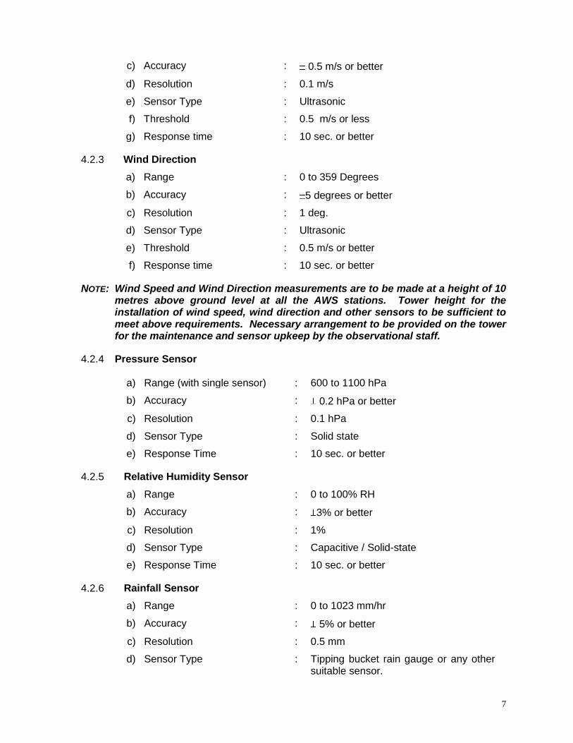
4.2.2 Wind Speed
a) Range (Operation) : 0 to 60m/s or better
b) Sustainability : Up to 75 m/sec
7
c) Accuracy : 0.5 m/s or better
d) Resolution : 0.1 m/s
e) Sensor Type : Ultrasonic
f) Threshold : 0.5 m/s or less
g) Response time : 10 sec. or better
4.2.3 Wind Direction
a) Range : 0 to 359 Degrees
b) Accuracy : 5 degrees or better
c) Resolution : 1 deg.
d) Sensor Type : Ultrasonic
e) Threshold : 0.5 m/s or better
f) Response time : 10 sec. or better
NOTE: Wind Speed and Wind Direction measurements are to be made at a height of 10 metres above ground level at all the AWS stations. Tower height for the installation of wind speed, wind direction and other sensors to be sufficient to meet above requirements. Necessary arrangement to be provided on the tower for the maintenance and sensor upkeep by the observational staff.
4.2.4 Pressure Sensor a) Range (with single sensor) : 600 to 1100 hPa
b) Accuracy : 0.2 hPa or better
c) Resolution : 0.1 hPa
d) Sensor Type : Solid state
e) Response Time : 10 sec. or better
4.2.5 Relative Humidity Sensor
a) Range : 0 to 100% RH
b) Accuracy : 3% or better
c) Resolution : 1%
d) Sensor Type : Capacitive / Solid-state
e) Response Time : 10 sec. or better
4.2.6 Rainfall Sensor
a) Range : 0 to 1023 mm/hr
b) Accuracy : 5% or better
c) Resolution : 0.5 mm
d) Sensor Type : Tipping bucket rain gauge or any other suitable sensor.
8
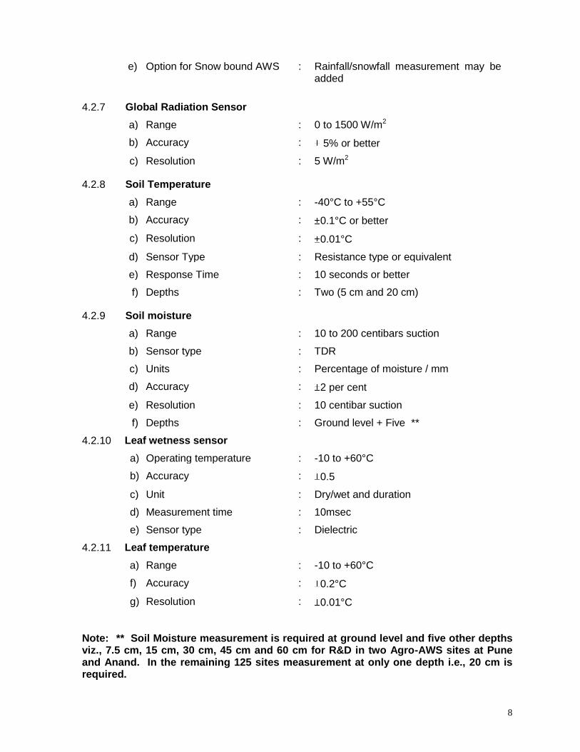
e) Option for Snow bound AWS : Rainfall/snowfall measurement may be added
4.2.7 Global Radiation Sensor
a) Range : 0 to 1500 W/m2
b) Accuracy : 5% or better
c) Resolution : 5 W/m2
4.2.8 Soil Temperature
a) Range : -40°C to +55°C
b) Accuracy : 0.1°C or better
c) Resolution : 0.01°C
d) Sensor Type : Resistance type or equivalent
e) Response Time : 10 seconds or better
f) Depths : Two (5 cm and 20 cm)
4.2.9 Soil moisture
a) Range : 10 to 200 centibars suction
b) Sensor type : TDR
c) Units : Percentage of moisture / mm
d) Accuracy : 2 per cent
e) Resolution : 10 centibar suction
f) Depths : Ground level + Five **
4.2.10 Leaf wetness sensor
a) Operating temperature : -10 to +60°C
b) Accuracy : 0.5
c) Unit : Dry/wet and duration
d) Measurement time : 10msec
e) Sensor type : Dielectric
4.2.11 Leaf temperature
a) Range : -10 to +60°C
f) Accuracy : 0.2°C
g) Resolution : 0.01°C Note: ** Soil Moisture measurement is required at ground level and five other depths viz., 7.5 cm, 15 cm, 30 cm, 45 cm and 60 cm for R&D in two Agro-AWS sites at Pune and Anand. In the remaining 125 sites measurement at only one depth i.e., 20 cm is required.
9
5. SPECIFICATIONS OF DATA LOGGER AND TRANSMISSION SYSTEM
5.1 Datalogger specifications
5.1.1 The system shall automatically collect the observations from attached sensors, process the same and store them into its memory as per the pre programmed procedure at every full hour UTC and data shall be transmitted to the INSAT-DRT in TDMA mode. Details of TDMA mode are provided in para 6.0. In-depth details of TDMA technique will be provided during the Design Review Committee Meeting which will be held with the successful bidder.
5.1.2 The system shall also send the values of meteorological parameters (user selectable) to a remote display unit located at a distance between 50 metres to 2 km depending on the location of each of the AWS site.
5.1.3 The number of analog/digital/ SDI channels in the data logger must be compatible to the sensors being supplied. Atleast four additional analog and digital channels each, extra RS-232, RS-485 and SDI -12 channels must be available to interface other types of sensors. The type and the number of extra channels provided in the data logger must be specified.
5.1.4 The sensor's signal conditioning unit should be an integral part of the system.
5.1.5 The system shall have provision to easily include and change the following information as mandatory requirements:
Unique station identification code
Time of observation
Sensor identification.
5.1.6 The system shall have an integrated microprocessor based data acquisition and storage system having adequate hardware configuration and software support to serve as an interface between sensors and the communication link to perform tasks as stated below:
5.1.6.1 Providing necessary electrical power to the sensors and conversion of electrical output signals from the sensors into engineering values based on calibration equations stored in the memory. Full compatibility with all types of sensors provided in the packages shall be mandatory.
5.1.6.2 Storage of observed data along with time for all the parameters in the memory. Memory capacity to retain at least one year’s data is required. Data shall be available even if the power supply to the system has failed (RAM Backup battery) for one year.
5.1.6.3 The stored data shall be retrievable via serial port to a PC/laptop and a PCMCIA card or any other compact and commercially available solid state memory device.
5.1.6.4 The system should be stand-alone and all programming functions/set-ups to be carried out through system keypad and display independent of a PC/Laptop.
10
5.1.6.5 The system should be capable of continuous updating of the values of sensed weather parameters and post processing the instantaneous values into average values over a specified period of time for transmission to the AWS earth station.
5.1.6.6 Management of data transmission to AWS earth station through satellite, which shall include formatting of transmitted data with necessary preambles, station ID codes, parity checks etc. as per transmission methodology for transmission through satellite channel, scheduling and operating the AWS transmitter automatically.
5.1.6.7 Management of AWS transmitter to optimize the battery consumption.
5.1.6.8 The system shall provide a complete health status of the battery, transmitter and other components.
5.1.6.9 The health data shall be stored as a log record and shall be capable of being retrieved and displayed when required.
5.1.6.10 The system shall have in-built sensor simulation system options to conduct tests on the system for field installation, two-point calibration/re-calibration and maintenance of the sensors.
5.1.6.11 The system shall have a weather-proof housing.
5.1.6.12 The system shall support the following functions:
Easy programming set up.
Multi tasking capability
User friendly software programming.
5.1.6.13 Transmission via satellite and / or telephone modem, selectable by the user.
5.1.6.14 The system shall have self-diagnostic facility and be capable of displaying Station ID/Sensor ID codes and messages on the display panel for general identification of the fault. Facility to monitor these codes and other health status through an external lap top/PC.
5.1.6.15 The system shall be provided with a keypad option and at least 16 character display in the front panel. Setup shall be organised in a tree of menus and sub-menus. Protection of setup parameters and data through password should be supported by the system. In addition, the AWS shall support the manual entry of data through keypad and its display.
5.1.6.16 Data including the setup and program files shall be transferable from the system via a serial port to PC and PCMCIA card or other suitable memory device and vice versa.
5.1.7 Analog to digital converter
Resolution : 16 bit or better
Conversion Accuracy : ± 1 LSB
5.1.8 System clock:
Stability Long-term : 1 ppm/year or better
Stability (Temperature) : 3 ppm or better from -40°C to 55°C

11
5.1.9 Operating Temperature range : -40°C to + 55°C
5.1.10 Internal Memory : 1 MB RAM minimum
5.1.11 Battery Backup (internal) : Lithium Battery, storage: 2 years
5.1.12 Real-Time Clock : GPS synchronised
5.1.13 Watchdog Timer : System Reset upon microprocessor failure
5.1.14 Sample Intervals : 1 sec. to 24 hr. in 1 second increments
(user selectable)
5.1.15 Visual display : 16 Character or more, alphanumeric LED/LCD to operate in temp. range -10°C to +55°C
5.1.16 Power consumption : Average over an hour shall be less than 0.5 A at 12V D.C. including that of sensors, GPS and transmitter.
5.1.17 Power Supply:
a) Battery :
Single 12V chargeable maintenance-free battery 65 AH capacity
b) Charge controller : Internal or External
c) Solar panel : Rated capacity 30W, Open circuit voltage: 21V, Short circuit current 2.4 A
5.2 AWS Transmitter & Antenna
The system transmitter should be an internal component of AWS. It should have necessary hardware and software to receive data from the datalogger and transmit either in TDMA mode as in para 6.0. The transmitter should have the capability to handle data transmission to the DRTs located on any of the INSAT series of satellites as given under Annexure I. The selection of frequency and mode of transmission shall be through software settings only. No hardware changes for switching from one satellite DRT to another are desirable.
5.2.1 Transmitter features 5.2.1.1 Carrier Frequency Band : 402.0 MHz - 403.0 MHz
Carrier frequency 402.658 MHz
5.2.1.2 Carrier Settability : In steps of 100 Hz from 402.0 MHz to 403.0 MHz
5.2.1.3 Modulator : PCM/BPSK
5.2.1.4 Data bit rate : 4.8 KBPS ( User selectable)
5.2.1.5 Data coding : NRZ(L)
5.2.1.6 Frequency stability:
a) Long term : Transmit frequency inaccuracy including
aging of oscillator should not exceed 400 Hz per year. Oscillator/synthesizer should have provision to adjust for the long term drift
12
b) for temperature : 1 ppm or better (-40 to +55oC)
5.2.1.7 Signal Bandwidth : 6.0 KHz maximum or better
5.2.1.8 Output Power : 3-10 W (settable)
5.2.1.9 Power Stability : 1 dB
5.2.1.10 Spurious : -60 dB or better
5.2.1.11 Harmonics : -40 dB or better
5.2.1.12 Environmental Operating Temperature
: -40°C to +55°C
5.2.1.13 Environmental Relative Humidity
: 0 to 100% RH for out door equipments
5.2.1.14 Operating power : Switched 12V D.C controlled by data
logger. 5.2.2 Antenna features
o The bidder shall ensure compatibility of the antenna in the entire system and also ensure achievement of objectives given in the telemetry link calculations to be provided by the bidder.
o The antenna shall have a proper mounting and pointing arrangement suitable for transmission to any one of INSAT satellites based DRTs (located anywhere in the geostationary arc from 45°E to 115°E longitude). The bidder shall also provide suitable templates and fixtures/tools for reorienting of the antenna towards any satellite by the field personnel as and when required.
o Proper lightning and surge protection shall be provided to protect all the equipment connected to the antenna from atmospheric hazards.
o Antenna to be designed with an optimum size so that it could be easily transported to remote and inaccessible places. Mounting of antenna should take care of Azimuth and Elevation changes. Systems have to operate in harsh and saline conditions and adaptable to tropical conditions.
o The following technical features shall be supplied by the bidder in addition to the technical information being provided by him as part of the bid.
5.2.2.1 Polarization : LHCP and RHCP (Switchable in field)
5.2.2.2 Gain : Minimum 11 dBi or better
5.2.2.3 Center frequency : 402.0 MHz to 403.0 MHz
5.2.2.4 3dB Beam width : 40o
5.2.2.5 VSWR : 1.2 : 1
5.2.2.6 Impedance : 50 ohms
5.2.2.7 Axial Ratio : To be specified by bidder
5.2.2.8 Operating wind speed : 250 kmph
5.2.2.9 Wind Survival : 300 kmph
13
5.2.2.10 Material : Rust-proof and oxidation-proof for use in coastal and saline areas
5.2.2.11 Connector type : To be specified by bidder
5.2.2.12 Mounting : Should have engraved elevation angle marking
5.2.2.13 Operating temperature : -40°C to +55°C
5.2.2.14 Operating Relative Humidity
: 0 to 100% RH
5.2.2.15 Weight : Light weight
5.2.2.16 Size : Small, portable
5.2.2.17 Operating rain rate : 100 mm/hr and water proof
5.3 Certification
Transmitter and data logger must have certification from IMD for functional operation through INSAT/Kalpana-1 satellites for either TDMA or PRBS (Pseudo Random Burst Sequence) type of transmission technique.
5.4 Requirements for Optional Display Unit
Slave display units to display the values of eight or more meteorological parameters near the premises of the AWS site are required. The following details are to be provided by the bidder.
5.4.1 Option for selection of sensors whose data is to be displayed is to be provided. 5.4.2 Measurement schedules for selected sensors (1minute, 2 minute, 5 minute) alongwith
option for displaying instantaneous or average values to be provided. 5.4.3 Selections required in the configuration and set up files to be provided.
5.4.4 Measured data should be sent to the display through a suitable output port, preferably RS-485 port so as to support a distance between 50 mtr to 2 km between AWS and display.
5.4.5 Suitable display unit compatible with the data logger having alpha-numeric LED display or background-lit LCD display with character height of two inches.
5.4.6 The display unit can be software programmable with a PC, if required.
5.4.7 The design of the display unit should be universal with compatibility to interface any type of datalogger.
5.4.8 Display unit should have independent power supply (AC Mains / Battery )
14
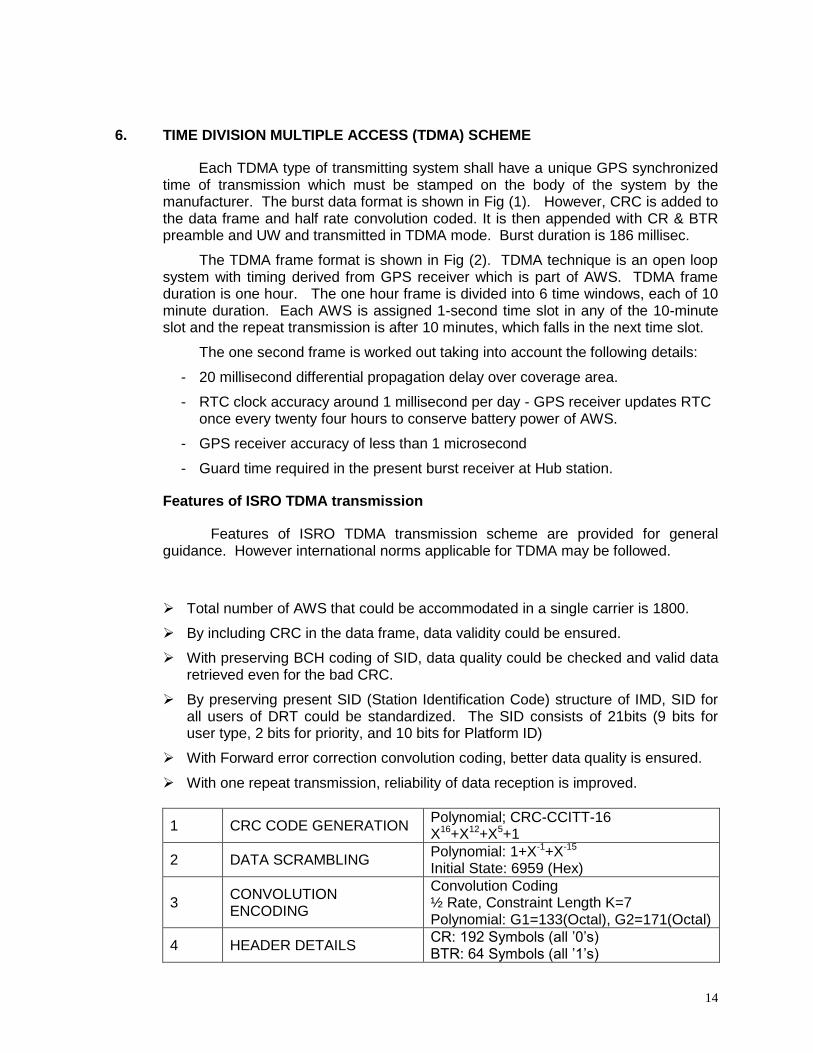
6. TIME DIVISION MULTIPLE ACCESS (TDMA) SCHEME
Each TDMA type of transmitting system shall have a unique GPS synchronized time of transmission which must be stamped on the body of the system by the manufacturer. The burst data format is shown in Fig (1). However, CRC is added to the data frame and half rate convolution coded. It is then appended with CR & BTR preamble and UW and transmitted in TDMA mode. Burst duration is 186 millisec.
The TDMA frame format is shown in Fig (2). TDMA technique is an open loop system with timing derived from GPS receiver which is part of AWS. TDMA frame duration is one hour. The one hour frame is divided into 6 time windows, each of 10 minute duration. Each AWS is assigned 1-second time slot in any of the 10-minute slot and the repeat transmission is after 10 minutes, which falls in the next time slot.
The one second frame is worked out taking into account the following details:
- 20 millisecond differential propagation delay over coverage area.
- RTC clock accuracy around 1 millisecond per day - GPS receiver updates RTC once every twenty four hours to conserve battery power of AWS.
- GPS receiver accuracy of less than 1 microsecond
- Guard time required in the present burst receiver at Hub station.
Features of ISRO TDMA transmission
Features of ISRO TDMA transmission scheme are provided for general guidance. However international norms applicable for TDMA may be followed.
Total number of AWS that could be accommodated in a single carrier is 1800.
By including CRC in the data frame, data validity could be ensured.
With preserving BCH coding of SID, data quality could be checked and valid data retrieved even for the bad CRC.
By preserving present SID (Station Identification Code) structure of IMD, SID for all users of DRT could be standardized. The SID consists of 21bits (9 bits for user type, 2 bits for priority, and 10 bits for Platform ID)
With Forward error correction convolution coding, better data quality is ensured.
With one repeat transmission, reliability of data reception is improved.
1 CRC CODE GENERATION Polynomial; CRC-CCITT-16 X16+X12+X5+1
2 DATA SCRAMBLING Polynomial: 1+X-1+X-15 Initial State: 6959 (Hex)
3 CONVOLUTION ENCODING
Convolution Coding ½ Rate, Constraint Length K=7 Polynomial: G1=133(Octal), G2=171(Octal)
4 HEADER DETAILS CR: 192 Symbols (all ’0’s) BTR: 64 Symbols (all ’1’s)
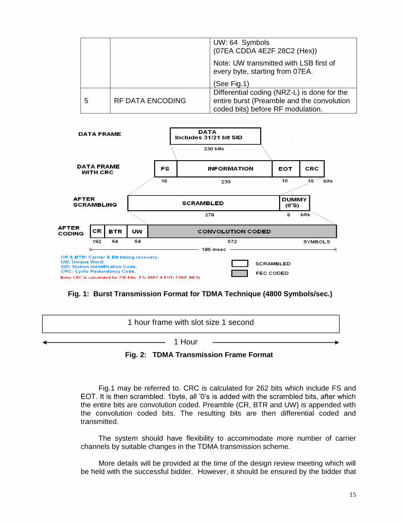
15
UW: 64 Symbols (07EA CDDA 4E2F 28C2 (Hex))
Note: UW transmitted with LSB first of every byte, starting from 07EA.
(See Fig.1)
5 RF DATA ENCODING Differential coding (NRZ-L) is done for the entire burst (Preamble and the convolution coded bits) before RF modulation.
Fig. 1: Burst Transmission Format for TDMA Technique (4800 Symbols/sec.)
Fig. 2: TDMA Transmission Frame Format
Fig.1 may be referred to. CRC is calculated for 262 bits which include FS and
EOT. It is then scrambled. 1byte, all ’0’s is added with the scrambled bits, after which the entire bits are convolution coded. Preamble (CR, BTR and UW) is appended with the convolution coded bits. The resulting bits are then differential coded and transmitted.
The system should have flexibility to accommodate more number of carrier
channels by suitable changes in the TDMA transmission scheme. More details will be provided at the time of the design review meeting which will
be held with the successful bidder. However, it should be ensured by the bidder that
1 hour frame with slot size 1 second
1 Hour
16
the system configuration is flexible and accommodate more than 30 sensors without any additional cost.
Table below gives the present AWS parameters and their identification
code used in the TDMA transmission format.
Sl.No. Channel No.
Identification Code
Parameter
1. 1 0000 (:0) Instantaneous sampled value of air temperature in deg C at the end of every full hour UTC.
2. 2 0001(:1) Max. air temperature of the hour (samples taken every minute).
3. 3 0010(:2) Minimum air temperature of the hour (samples taken every minute).
4. 4 0100(:4) Wind speed in knots (3 minute vector averaging prior to full hour UTC).
5. 5 0101(:5) Wind direction in degrees (3 minute vector averaging prior to full hour UTC).
6. 6 0110(:6) Station level pressure (sampled at the end of every full hour UTC).
7. 7 0111(:7) Instantaneous value of RH at the end of every full hour UTC.
8. 8 1100(:12) Cumulative rainfall since last reset (reset at every 03 UTC everyday), rounded off to the next higher integer.
9. 9 1101(:13) Hourly soil temperature
10. 10 1110(:14) Duration of bright sunshine since last 20 UTC. Reset to zero at 20 UTC. (Global radiation will be transmitted in this slot instead of duration of sunshine.
11. Cal1 :C1 Battery voltage (volts)
12. Cal2 :C2 Hourly rainfall (rounded off to next higher integer).
13. Cal3 :C3 Hourly soil moisture
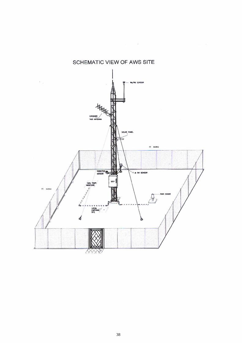
7. AWS SITE PREPARATION
The bidder shall prepare the AWS site according to the details and layout given in Annexure-II in different parts of India. It is to be ensured that IMD’s representative is present at the site at the time of site preparation / installation and official commissioning of the AWS site. All cabling in the AWS site should be concealed/underground using suitable GI/steel piping /conduits. Each site should have a good quality metal sign board (Size: Height 2 ft x width 3 ft) painted in English or Hindi, as per the State where AWS is located with the following information:
17
Government of India
India Meteorological Department
AUTOMATIC WEATHER STATION (Name of the station)
Contact: Dy. Director General of Meteorology (Surface Instruments)
INDIA METEOROLOGICAL DEPARTMENT Shivajinagar, PUNE – 411 005. Phone: 020 - 25535411 Fax : 020 - 25521529
(Property of Govt. of India. Trespassers will be prosecuted)
Fig. 3: Details for metal sign board
8 SPECIFICATIONS OF EARTH STATION EQUIPMENTS
All components of the earth station equipment shall be compatible with TDMA transmission techniques. Accordingly equipment required for reception and processing the data may be provided. The whole system shall have complete redundancy.
Detailed specifications of the equipment required like down converter,
demodulator, processing software will be discussed at the time of Design Review Meeting with the successful bidder.
A general overview of the requirement is given below: 8.1 General features
8.1.1 The ground station to be installed at IMD Office, Pune should continuously receive the data transmitted by all AWS in India and neighbourhood. The received data should be decoded in real time for extraction of the actual values of meteorological parameters and station names with sensor identifications.
8.1.2 The ground station shall be based on latest state-of-the-art, digital technology for rugged and reliable operation under all types of adverse environmental conditions.
8.1.3 The earth station shall be capable of receiving downlink transmissions in the entire 300 MHz band (4500 – 4800 MHz) from any of the DRTs on board INSAT / KALPANA- series of satellites 1 (LHCP/RHCP polarizations).
8.1.4 The earth station shall have the capability to provide an overall performance of better than 99% of error free data which shall be demonstrated by the bidder as part of the acceptance test procedures. The proof of actual performance of a similar system if already functioning elsewhere shall also be supplied with the bid.
8.1.5 The receive station shall have necessary software for interfacing with a processing computer. The supply of processing computer along with its software is also part of
18
the bid. The software should convert the meteorological data values of all stations for every hour into a WMO synop format (Annexure- IV) to disseminate the data in real time automatically through FTP (File Transfer Protocol) over a dedicated leased line connection available at AWS lab, Pune, IMD to a switching computer located at AMSS Mumbai for onward transmission to GTS.
8.1.6 All civil works associated with the installation of outdoor and indoor equipments shall be the responsibility of the bidder.
8.2 Hardware features
8.2.1 All necessary mechanisms and pointing arrangements for switching from one INSAT satellite to another in orbital positions from 45°E to 115°E shall be provided.
8.2.2 Indication of position of antenna (azimuth & elevation angles may be engraved in the pedestal of the antenna.
8.2.3 The LNA shall be 1+1 with redundancy and a control unit should be provided for automatic switching from one LNA to the other.
8.2.4 The down converter (1+1) shall be capable of receiving downlink transmissions in the entire 300 MHz band (4500 to 4800 MHz). It shall have rear panel connectors for IF input to the receiver and IF monitor point for the spectrum analyzer.
8.2.5 Synthesized Digital Signal Processor (DSP) based demodulator/ receiver. Full specifications to be provided in the tender offer.
8.2.6 Front panel indicators for pilot lock, channel activity and diagnostics
8.2.7 Automatic time synchronization using GPS among different components of the earth station. GPS shall be part of the supply.
8.2.8 The processing computer shall have capability to set up different channel assignments, change demodulation characteristics, monitor signal quality and diagnostics capability.
8.2.9 The processing computer shall have facility for complete control and customization of the ground station operations and diagnostics
8.2.10 The mains power shall be supplied out of a wall mounted Indian standard outlet at 230VAC +10%, 50Hz. The bidder shall include all necessary cables, connectors, On-line UPS (5 KVA, 12 hours back-up) preferably APC-make, surge and lightning protection for safe and stable power supply to the receiver.230 V +10%, 50 Hz AC supply operation
8.2.11 The battery backup provided by the online UPS shall be 12 hrs at full load in redundant mode.
8.2.12 The bidder shall offer complete redundancy of critical components with a receiver indoor or outdoor electronics with facilities for automatic take over and appropriate alarms to commence maintenance of defective components.

19
8.3 Details of earth station antenna The following features shall be provided by the bidder. Any additional options
available in respect of any of the features shall be clearly brought out with the recommendations for a specific option selection.
8.3.1 Reflector size : 3.8 metres or less diameter.
8.3.2 Reflector type : Solid fibre glass material
8.3.3 Mount Design : Polar mount / any other suitable design (TBS)
8.3.4 Feed Mount : Prime focus feed
8.3.5 Feed type : Linear
8.3.6 Input frequency (for feed) 4.5 to 4.8 GHz
8.3.7 G/T : 31.7 dB / K
8.3.8 Operating frequency : 4500- 4800 MHz
8.3.9 Gain : >=43 dB
8.3.10 Polarization : LHCP / RHCP selectable
8.3.11 Elevation Adjustment Range : 0-90 ( Coarse & fine adjustment) Angles to be engraved on the antenna
8.3.12
Azimuth Adjustment Range : 0-360 (Coarse & fine adjustment) Angles to be engraved on the antenna
8.3.13 Wind loading : a) Operational
:
100 KMPH or better
b) Survival : 175 KMPH or better
8.3.14 Operating rainfall rate : 100mm/hr and water proof.
8.4 Features of LNA
The following features shall be provided by the bidder. Any additional options available in respect of any of the features shall be clearly brought out with the recommendations for a specific option selection.
Frequency range : 4500 – 4800 MHz
Bandwidth : 300 MHz(typical)
Noise temperature
(Ambient Temp. 25°C)
: <=50 K (45 K typical)
Gain : >= 60 dB
Gain ripple : Not more than 0.5 dB (Over entire 300 MHz pass band)
Max. RF input : -50 dBm composite
Max. RF input with no damage
: 0 dBm CW in pass band

20
Input / Output VSWR : (4.5 GHz to 4.8 GHz )
: 1.2 : 1
Operating Temperature : 0 to 55 oC
Humidity : 0-100 per cent with condensation 8.4.1 Switching of redundant LNA
A redundant LNA should also be mounted in parallel with the primary LNA. The system controller should automatically switch over the LNA to the redundant one by sensing a change in the amplifier current. A provision of manual switchover should also be available. The amplifiers and switches should be weatherproof and designed for mounting at the feed.
8.5 Features of Synthesized Down converter
The general features are provided below.
RF input : 4500 – 4800 MHz
IF output range : Compatible to Demodulator Input (May be 100-180 MHz)
IF bandwidth :
Frequency sensing :
RF input level : -55 dBm typical
RF input noise figure :
IF Attenuation :
IF output level : +20 dBm at 1 dB compression
Total conversion gain :
Spurious and LO leakage :
Image rejection :
Frequency stability over time : +/- 1 x 10⁻⁹ / day
Frequency stability over temperature : +/- 1 x 10⁻⁸ / day
Frequency step resolution :
Test points :
Operating Power :
Power dissipation :
Environmental operating temp. range :
Environmental operating humidity range :
8.6 Features of Digital Receiver / BPSK Demodulator
All features of the receiver / demodulator have to be provided by the bidder for full compatibility to TDMA processing. General features are listed below.
21
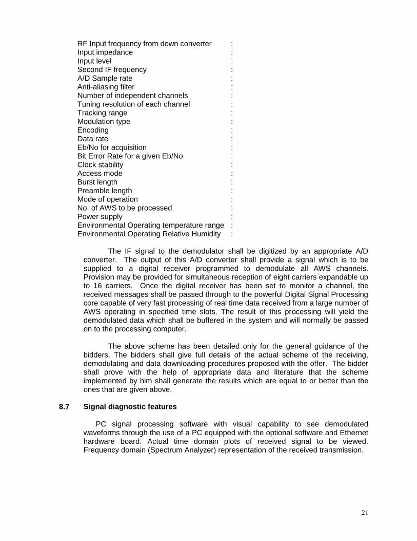
RF Input frequency from down converter : Input impedance : Input level : Second IF frequency : A/D Sample rate : Anti-aliasing filter : Number of independent channels : Tuning resolution of each channel : Tracking range : Modulation type : Encoding : Data rate : Eb/No for acquisition : Bit Error Rate for a given Eb/No : Clock stability : Access mode : Burst length : Preamble length : Mode of operation : No. of AWS to be processed : Power supply : Environmental Operating temperature range : Environmental Operating Relative Humidity :
The IF signal to the demodulator shall be digitized by an appropriate A/D converter. The output of this A/D converter shall provide a signal which is to be supplied to a digital receiver programmed to demodulate all AWS channels. Provision may be provided for simultaneous reception of eight carriers expandable up to 16 carriers. Once the digital receiver has been set to monitor a channel, the received messages shall be passed through to the powerful Digital Signal Processing core capable of very fast processing of real time data received from a large number of AWS operating in specified time slots. The result of this processing will yield the demodulated data which shall be buffered in the system and will normally be passed on to the processing computer.
The above scheme has been detailed only for the general guidance of the
bidders. The bidders shall give full details of the actual scheme of the receiving, demodulating and data downloading procedures proposed with the offer. The bidder shall prove with the help of appropriate data and literature that the scheme implemented by him shall generate the results which are equal to or better than the ones that are given above.
8.7 Signal diagnostic features
Si PC signal processing software with visual capability to see demodulated waveforms through the use of a PC equipped with the optional software and Ethernet hardware board. Actual time domain plots of received signal to be viewed. Frequency domain (Spectrum Analyzer) representation of the received transmission.
22
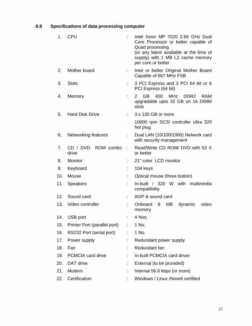
8.8 Specifications of data processing computer
1. CPU : Intel Xeon MP 7020 2.66 GHz Dual Core Processor or better capable of Quad processing (or any latest available at the time of supply) with 1 MB L2 cache memory per core or better
2. Mother board : Intel or better Original Mother Board Capable of 667 MHz FSB
3. Slots : 3 PCI Express and 3 PCI 64 bit or 6 PCI Express (64 bit)
4. Memory : 2 GB 400 MHz DDR2 RAM upgradable upto 32 GB on 16 DIMM slots
5. Hard Disk Drive : 3 x 120 GB or more
10000 rpm SCSI controller ultra 320 hot plug.
6. Networking features : Dual LAN (10/100/1000) Network card with security management
7. CD / DVD ROM combo drive
: Read/Write CD ROM/ DVD with 52 X or better
8. Monitor : 21" color LCD monitor
9. Keyboard : 104 keys
10. Mouse : Optical mouse (three button)
11. Speakers : In-built / 320 W with multimedia compatibility
12. Sound card : AGP & sound card
13. Video controller : Onboard 8 MB dynamic video memory
14. USB port : 4 Nos.
15. Printer Port (parallel port) : 1 No.
16. RS232 Port (serial port) : : 1 No.
17. Power supply : Redundant power supply
18. Fan : Redundant fan
19. PCMCIA card drive : In-built PCMCIA card driver
20. DAT drive : External (to be provided)
21. Modem : Internal 56.6 kbps (or more)
22. Certification : Windows / Linux /Novell certified
23
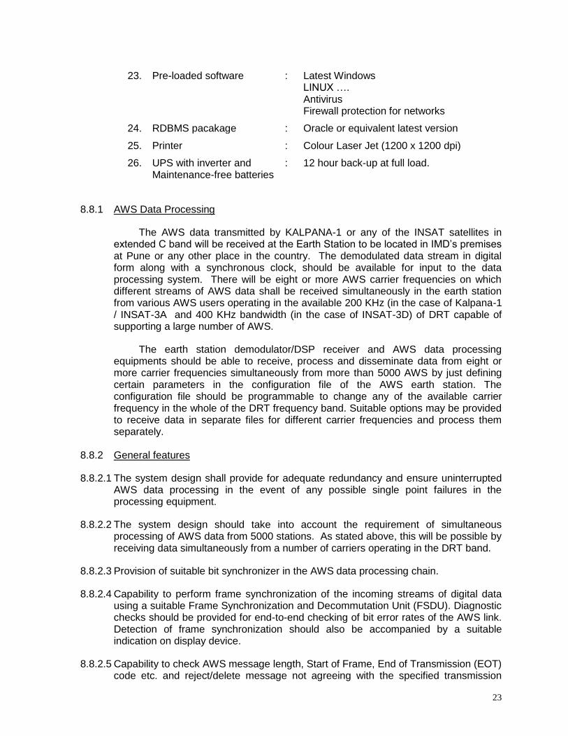
23. Pre-loaded software : Latest Windows LINUX …. Antivirus Firewall protection for networks
24. RDBMS pacakage : Oracle or equivalent latest version
25. Printer : Colour Laser Jet (1200 x 1200 dpi)
26. UPS with inverter and Maintenance-free batteries
: 12 hour back-up at full load.
8.8.1 AWS Data Processing
The AWS data transmitted by KALPANA-1 or any of the INSAT satellites in extended C band will be received at the Earth Station to be located in IMD’s premises at Pune or any other place in the country. The demodulated data stream in digital form along with a synchronous clock, should be available for input to the data processing system. There will be eight or more AWS carrier frequencies on which different streams of AWS data shall be received simultaneously in the earth station from various AWS users operating in the available 200 KHz (in the case of Kalpana-1 / INSAT-3A and 400 KHz bandwidth (in the case of INSAT-3D) of DRT capable of supporting a large number of AWS.
The earth station demodulator/DSP receiver and AWS data processing equipments should be able to receive, process and disseminate data from eight or more carrier frequencies simultaneously from more than 5000 AWS by just defining certain parameters in the configuration file of the AWS earth station. The configuration file should be programmable to change any of the available carrier frequency in the whole of the DRT frequency band. Suitable options may be provided to receive data in separate files for different carrier frequencies and process them separately.
8.8.2 General features
8.8.2.1 The system design shall provide for adequate redundancy and ensure uninterrupted AWS data processing in the event of any possible single point failures in the processing equipment.
8.8.2.2 The system design should take into account the requirement of simultaneous processing of AWS data from 5000 stations. As stated above, this will be possible by receiving data simultaneously from a number of carriers operating in the DRT band.
8.8.2.3 Provision of suitable bit synchronizer in the AWS data processing chain.
8.8.2.4 Capability to perform frame synchronization of the incoming streams of digital data using a suitable Frame Synchronization and Decommutation Unit (FSDU). Diagnostic checks should be provided for end-to-end checking of bit error rates of the AWS link. Detection of frame synchronization should also be accompanied by a suitable indication on display device.
8.8.2.5 Capability to check AWS message length, Start of Frame, End of Transmission (EOT) code etc. and reject/delete message not agreeing with the specified transmission
24
format. If another “Start of Frame” occurs before EOT, that particular AWS data may be rejected and suitable message indicating “Collisions” may be echoed on system terminal.
8.8.2.6 Capability for amendment of number of AWS stations and their parameters stored in the AWS station configuration file.
8.8.2.7 Check for errors in the station ID based on BCH code and parity errors in the sensor data stream.
8.8.2.8 Check whether the AWS messages received correspond to the allotted 10 minute transmission window and select only one best AWS message out of the three received. Parity check of data bits has to be done. Data to be accepted if parity check is alright, otherwise data may be called invalid and rejected.
8.8.2.9 Out of the messages accepted for a particular station every hour, the values of meteorological parameters are to be compared with each of those received in that hour and identical ones are to be displayed. Any random data needs to be rejected.
8.8.2.10 Check for BCH Code and apply standard code for forward error correction. The code used for error corrections and the precise methodology proposed to be adopted for this, together with software used, should be included in the tender offer.
8.8.2.11 If for a particular station and time more than three messages are received, the station ID and the time of observation should be reported.
8.8.2.12 Data corresponding to the best AWS message for each hour of observation and for each station is to be converted into meteorological parameters corresponding to the station name, time of observation, and sensor values.
8.8.2.13 The derived meteorological parameters are to be compared with corresponding values of previous hour(s) and / or preset limits. Those found to be beyond the tolerance limits should be flagged and be available for operator’s interventions/correction/deletion. Suitable flags to be provided on operator’s console for intervention in case any error is detected in the incoming message. The present threshold limits have to be based on surface meteorological normals for various parameters which will be provided by the department at the time of implementation of the project to the selected vendor.
8.8.2.14 The final output of AWS data should be formatted, and/or printed on a printer and also stored on appropriate data base disk for next 4-8 weeks.
8.8.2.15 Facility to automatically transmit the synop messages in WMO format through a dedicated leased line provided by IMD. The synop messages should be generated in BUFR code format also.
8.8.2.16 If all messages received from an AWS have parity errors, this may be reported in the summary.
8.8.2.17 The processing software should have capability to derive a number of standard statistical functions with the processed data for each parameter, for R&D / quick analysis of data quality.
25
8.8.2.18 Capability to monitor the number of messages received from the individual AWS stations and to provide an hourly summary/daily summary of missing and received messages parameter-wise on operator’s command in the form of engineering print out.
8.8.2.19 Provision of a suitable AWS data simulator in the processing system for quick checking of all functionalities of the data processing sub-systems.
8.8.2.20 Capability to extract all the meteorological parameters or to select any particular meteorological parameters from the processed data stored on the data base disk along with the latitude/longitude information.
8.8.2.21 Capability to generate suitable reports on hard copy device indicating:
i) AWS which report more than 3 messages in 10 minutes time-slot
ii) AWS transmitting data in non-scheduled time windows
iii) Daily / Monthly transmission reports for all AWS enabled for monitoring
iv) Monthly / Seasonal rainfall reports for all AWS
8.8.2.22 If data of a particular sensor is received out of range or with parity errors, the software should be such that data is still processed, and that the data for erratic sensor alone is not transmitted to the users and suitable report is generated on the hard-copy terminal for operator’s action.
8.8.2.23 Facility to block data of any one or more AWS from transmission to the users as and when required due to any reason.
8.8.2.24 Facility to block data of any one or more sensors for selected stations from transmission to the users as and when required due to problem in sensors at few stations.
8.8.2.25 Facility to print 24 hours statistics for each AWS giving details of total number of messages received, number of messages valid/invalid, number of errors, data quality etc.
8.8.2.26 Facility to selectively stop the processing of AWS data of any particular station/stations if found to be behaving erratically.
8.8.2.27 Facility to report error messages on operator console and store in a log for detailed examination.
The software module shall include a wide range of error messages, to provide information in respect of various error conditions as detailed below. The errors listed below are the minimum and the bidder shall describe various other errors also that can be tapped and displayed by the software offered.
o Last Receipt of data o Garbage data o Data with improper format o Overflow of data o Protocol Analysis o Receipt of data from another channel
26
o Invalid parameters o Transmission and radio frequency interference related problems o Parity error related problems.
8.8.3 Archival
Necessary software for archival and retrieval of all processed AWS data on 4 mm/ 8 mm DATs / 12GB DLTs to be provided by the tenderer. Full details of the analysis of tape length requirements, CD ROMs / DATs / DLTs etc., for recording 24 hours of data from 5000 AWS, shall be included in the tender offer. Archival should be of finally processed, edited and corrected data sets with all the auxiliary information required to identify the data sets. Full details of error characteristics of the data should also be archived.
Data archival from data base to the tapes / CD ROMs may be once in a month. Tape archival format shall also be supplied by the tenderers with full details. Format should be of standard type for ease of use by various users.
8.8.4 Software deliverables
8.8.4.1 Source code of all aspects of the AWS data receiving and processing software for the Earth Station is to be provided.
8.8.4.2 The necessary compilers and libraries required for recompilation of the source code after any modifications shall also be inclusive in the supply.
8.8.4.3 The supply shall be inclusive of complete software modules running on the system for provision of complete functionality as described above. The supplier shall mention all the modules which are available along with their costs for selection of any one or more of them. The essential modules which are obligatory for a standard system performance shall be indicated separately.
8.8.4.4 The system shall have appropriate operating system software to provide password protection of different levels for system setting and data downloading operations etc.
8.8.4.5 The software shall support and include a suitable application like Oracle or other standard RDBMS for management of the database.
8.8.4.6 The system shall include software for the following facilities:
Setting up station parameters, importing data files, provision to edit or modify existing set up of receiver ground station.
Network Management: The facility for detailed analysis of working status of field stations and sensors. GIS base graphical output shall be provided.
Data Management: The package shall manage the data received from the AWS and provide facilities for display, graph, and printouts in various formats.
Trouble shooting: Test and Troubleshoot a Receiver Ground Station System including analysis of protocols and initialization of calibration and health checking.
27
Data Translation: Translation of downloaded data files into standard ASCII, RDBMS formats.
Data Plotting: To generate surface meteorological charts and analysed charts.
Tutorial: An online tutorial shall be available for access by the users. It should include a step-by-step procedure for familiarizing with all the features of the software package.
8.8.4.7 Facility to develop/find out station ID for all AWS stations (BCH code or any standard forward error correcting code) in binary as well as hexadecimal code.
8.8.4.8 Facility to find out AWS antenna azimuth / elevation for a particular sub-satellite point.
8.8.4.9 Facility to generate surface meteorological charts using all available data in standard format.
8.8.4.10 Facility to generate analysed surface meteorological charts such as isobars, isotherms, stream lines, isohyets and other standard analysis techniques on India map. Details will be provided at the time of design review meeting.
8.8.4.11 Final plotted and analysed output of meteorological charts should be printed through a plotter which is to be provided by the bidder.
8.8.4.12 Software for maintenance/servicing/data retrieval schedule for all AWS stations (upkeep of meta data of AWS station).
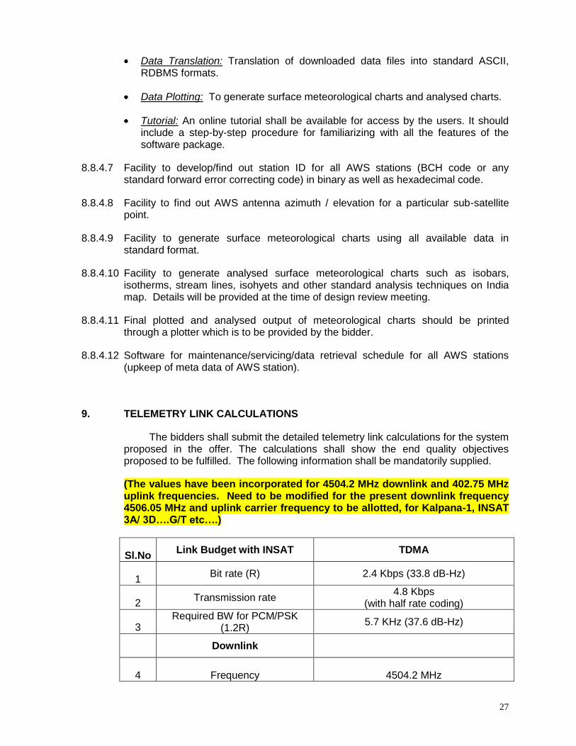
9. TELEMETRY LINK CALCULATIONS
The bidders shall submit the detailed telemetry link calculations for the system proposed in the offer. The calculations shall show the end quality objectives proposed to be fulfilled. The following information shall be mandatorily supplied.
(The values have been incorporated for 4504.2 MHz downlink and 402.75 MHz uplink frequencies. Need to be modified for the present downlink frequency 4506.05 MHz and uplink carrier frequency to be allotted, for Kalpana-1, INSAT 3A/ 3D….G/T etc….)
Sl.No Link Budget with INSAT TDMA
1 Bit rate (R) 2.4 Kbps (33.8 dB-Hz)
2 Transmission rate
4.8 Kbps (with half rate coding)
3 Required BW for PCM/PSK
(1.2R) 5.7 KHz (37.6 dB-Hz)
Downlink
4 Frequency 4504.2 MHz
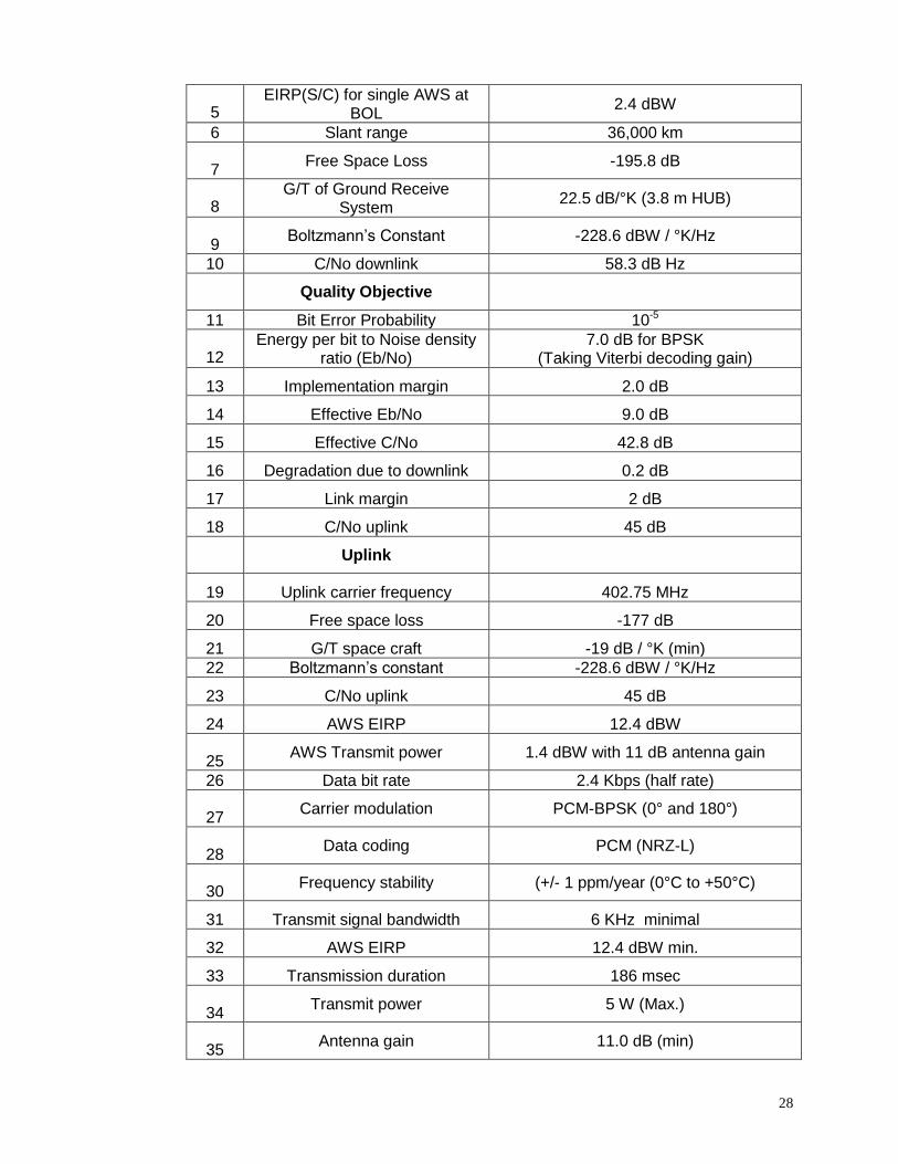
28
5 EIRP(S/C) for single AWS at
BOL 2.4 dBW
6 Slant range 36,000 km
7 Free Space Loss -195.8 dB
8 G/T of Ground Receive
System 22.5 dB/°K (3.8 m HUB)
9 Boltzmann’s Constant -228.6 dBW / °K/Hz
10 C/No downlink 58.3 dB Hz
Quality Objective
11 Bit Error Probability 10-5
12 Energy per bit to Noise density
ratio (Eb/No) 7.0 dB for BPSK
(Taking Viterbi decoding gain)
13 Implementation margin 2.0 dB
14 Effective Eb/No 9.0 dB
15 Effective C/No 42.8 dB
16 Degradation due to downlink 0.2 dB
17 Link margin 2 dB
18 C/No uplink 45 dB
Uplink
19 Uplink carrier frequency 402.75 MHz
20 Free space loss -177 dB
21 G/T space craft -19 dB / °K (min)
22 Boltzmann’s constant -228.6 dBW / °K/Hz
23 C/No uplink 45 dB
24 AWS EIRP 12.4 dBW
25 AWS Transmit power 1.4 dBW with 11 dB antenna gain
26 Data bit rate 2.4 Kbps (half rate)
27 Carrier modulation PCM-BPSK (0° and 180°)
28 Data coding PCM (NRZ-L)
30 Frequency stability (+/- 1 ppm/year (0°C to +50°C)
31 Transmit signal bandwidth 6 KHz minimal
32 AWS EIRP 12.4 dBW min.
33 Transmission duration 186 msec
34 Transmit power 5 W (Max.)
35 Antenna gain 11.0 dB (min)
29
36 Antenna polarisation
Left / Right hand circular polarization (field selectable)
10. TRAINING TO IMD OFFICIALS
The manufacturer / supplier should provide in-depth training in hardware and software to at least TEN IMD officers in the installation, operation and maintenance of the system, TDMA receiving earth station and about all software aspects including source code, at the manufacturer’s place for a minimum period of four weeks. The firm will bear the cost of IMD officers towards travel expenses and per diem at Govt. of India rates.
11. WARRANTY AND MAINTENANCE
The manufacturer should provide a free comprehensive warranty of at least two years after commissioning of the system in the field. The manufacturer should simultaneously take on the work of servicing and routine maintenance of field equipment once in three months. Response time for rectifications of faults in the field AWS equipment should not be more than two days. If the down time is more than two days, the warranty period will be presumed to be extended by a period twice the down time.
Reports of maintenance visits should be submitted on a quarterly basis to the respective regional maintenance centres along with a copy to DDGM(SI), Pune. Analysis of the data quality with a co-located meteorological observatory, if available, should be submitted. Hand-held digital standards for pressure, air temperature, relative humidity should be compulsorily available with the firm and taken to the AWS sites by the maintenance party to compare and evaluate the data quality. Hand-held GPS should be carried to the sites to get the correct geographical coordinates of the sites.
In the case of indigenous firms, 80% of the total cost of equipment will be paid
on receipt and acceptance of the material at Pune. 20% of the balance amount will be paid after final commissioning and acceptance of the AWS.
In the case of import of equipments, 90% of the total cost of equipment will be
paid upon opening of Letter of Credit and the balance 10% will be paid after final commissioning and acceptance of AWS.
No advance payment will be made towards installation charges. Payment will
be made in instalments for every 50 AWS sites commissioned and accepted.
12. TESTING, INSTALLATION & CALIBRATION KIT
The supplier shall provide 50 sets of kits of all equipment, meters, tools and test kits required for the purpose, including telecommunication equipment. The kit shall have all the necessary jigs, tools and fixtures required for installation and dismounting of telecommunication equipment, including antennae and associated cables of all types. All the tools and fixtures required for mounting and dismounting all the equipment from their respective installation sites shall be included.
30
13. DOCUMENTATION
The authorisation of representation from the manufacturer of the equipment should be submitted by the bidder along with the technical bids. The manufacturer should provide detailed manuals for operation, servicing and maintenance of each sub system including all block diagrams and detailed circuit diagrams. The catalogues of all the vital components used in the system should also be provided. The copies of software listings may be provided in the form of CD ROMs or other suitable media. All manuals should be given in printed form also.
14. COMPLIANCE / NON-COMPLIANCE STATEMENT
The tenderer shall submit a detailed item-wise compliance / non-compliance statement referring para-wise to the requirements given in this document, for quick evaluation of tender and for any future reference. The compliance statement shall be supported by original brochure(s) of the equipment or sub component from the manufacturer. In case the original brochure is silent on any part of tender specification, it shall be supported by an undertaking by the manufacturer, if claimed complied. The technical specifications and other requirements contained in this document are essentially required by the indenter. However, reasons for non-compliance, if any, for certain limited paras, or even sub-paras of the document may also be given by the tenderer. Silence on any part of the technical specification or failure / omission to provide any such details will be treated as non-compliance. All non-compliance of specifications, even of small nature, should be clearly brought out.
15. RELIABILITY
In general, it is desired that sensors should be capable of operating for 2-3 years without physical technical intervention. Sensors and AWS system should have built-in performance checks and indicators which should be utilized whenever possible.
16. SPARES AND CONSUMABLES
The manufacturer should submit a list of critical spares including sensors and components for operating these systems for a period of 2 years after the expiry of warranty period. The cost of these spares to be restricted within 15 per cent of the total cost of equipment.
A list of accessories and test equipment along with their cost should also be submitted by the manufacturer along with the offer.
The manufacturer should also quote for all the required supporting structures, housing, masts, shelters etc along with the main equipment.
17. INSTALLATION, SYSTEM INTEGRATION AND COMMISSIONING
Land based AWS will be located in a fenced plot of land measuring 15 m X12 m having adequate exposure for sensors. The area of the site for Agro-AWS is 15 m x 15 m located in a bigger site of dimensions 36 m x 36 m.

31
One test-AWS and one Agro-AWS are required to be installed in Pune for test and evaluation and complete testing of configuration of agro-related parameters.
The bidding firm should undertake the installation work in the presence of IMD personnel who will officially commission the AWS after verification of the data quality. A report on the data quality of the AWS is also required to be submitted by the firm after ensuring data reception at the Earth Station, Pune.
Transportation of equipment from Pune to AWS at field sites all over India is also part of the contract. In order to ensure safety during transportation, proper insurance shall be arranged by the bidder.
18. DELIVERY SCHEDULE
Complete set of data loggers and transmission systems (550 Nos.):
(a) Delivery : In two approx. equal parts
First consignment: Six months from the date of award of contract. Second consignment: 12 months from the date of award of contract.
(b) Commissioning : Two years (for all 550)
In case of delay of supply of the consignment, liquidated damage charge will be imposed @ 2% in delay of every month or its part to a maximum of 10%.
Delivery of the equipment should be done at the O/o DDGM(SI) Pune free of cost. The equipment must be under insurance during transportation.
If the bidder is unable to execute the project to the satisfaction of consignee, IMD
has the right to re-tender after giving adequate notice to the supplier. The cost of re-tendering demurrage and the difference in the cost, if any, of the new order would be payable by the supplier.
19. PRICE PROPOSAL
The bidder shall submit the detailed price proposal containing separately, item-wise, the prices for each and every deliverable item and support services like fencing and other civil works separately. Since the plot size may vary, different items of the work for site preparation may be quoted as rate per square metre or per metre as the case may be.
The price proposal should be given in a separate sealed cover. Technical
document should contain an exact copy of the price bid without revealing the price details.
List of deliverables is given in Annexure-V.
32
20. TESTING AND ACCEPTANCE
The bidder shall submit testing and acceptance plan for comments by IMD. The systems will be tested and evaluated in the laboratory at Pune according to the document.
21. SITE PREPARATION
The preparation of the AWS field sites will be taken up by the bidder after placing the firm order as per the agreed site preparation layout document (Annexure-II).
(Note: The value and number based specifications specified above can be marginally modified by the individual supplier in order to meet the specific system design offered by him. Wherever such modifications are suggested, the supplier shall clearly bring out the benefits that may accrue by way of these modifications of the specific parameters. If any parameter value is changed without giving full justification in the bid, the same shall be treated as a material deviation from technical specifications)
22. SYSTEM DESIGN REVIEW
After award of contract a detailed design review meeting will be conducted where full technical details of the system will be mutually discussed between IMD and vendor’s engineers. A detailed design review document needs to be provided by the supplier. The full technical details of the AWS system, TDMA technique and all required hardware aspects of the AWS and the components of the Receiving Earth Station will be discussed and finalized in the Design Review Meeting. Test plan and general test procedures will also be discussed during this review. Detailed procedures for conducting Acceptance Tests will be finalized subsequently based on the outcome of discussions in the design review.
33
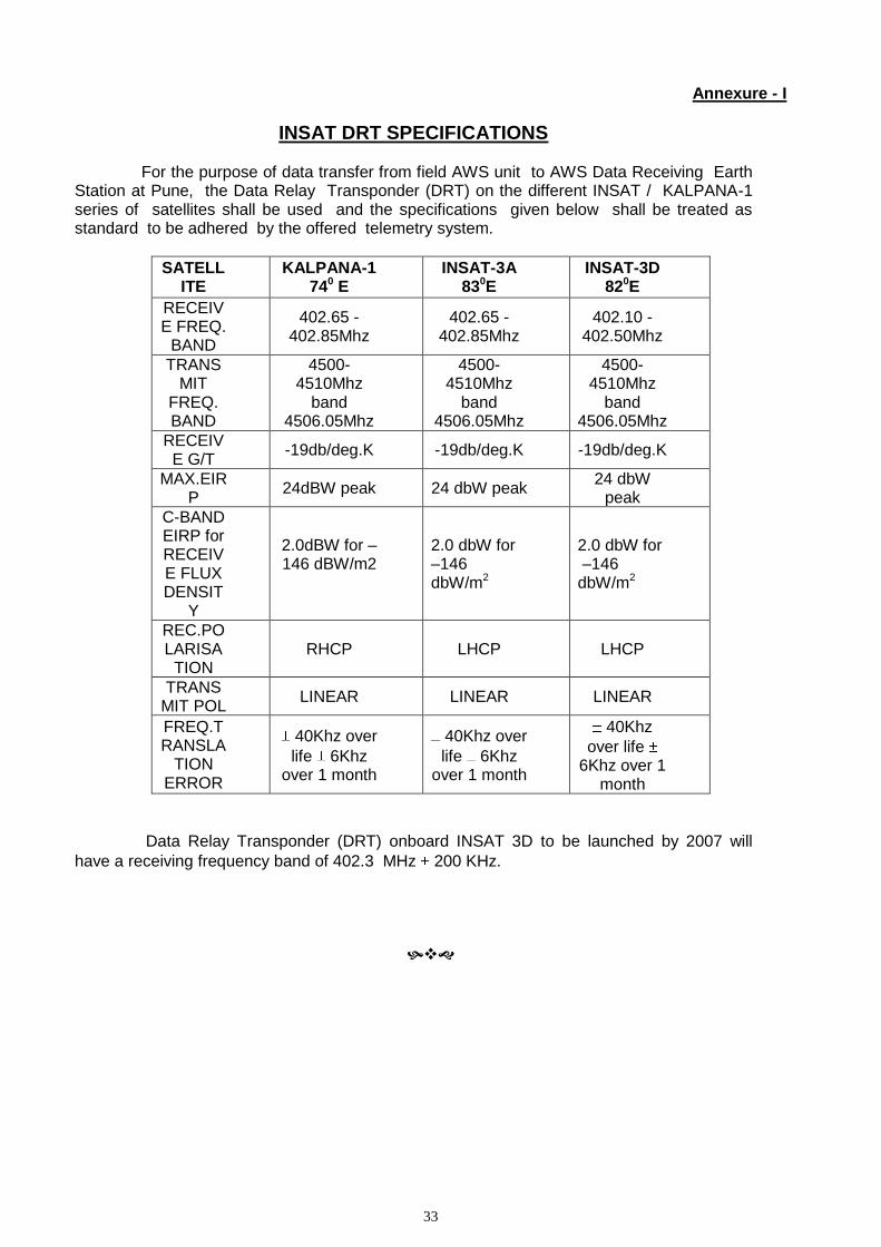
Annexure - I
INSAT DRT SPECIFICATIONS For the purpose of data transfer from field AWS unit to AWS Data Receiving Earth Station at Pune, the Data Relay Transponder (DRT) on the different INSAT / KALPANA-1 series of satellites shall be used and the specifications given below shall be treated as standard to be adhered by the offered telemetry system.
SATELLITE
KALPANA-1 740 E
INSAT-3A 830E
INSAT-3D 820E
RECEIVE FREQ.
BAND
402.65 - 402.85Mhz
402.65 - 402.85Mhz
402.10 - 402.50Mhz
TRANSMIT
FREQ. BAND
4500-4510Mhz
band 4506.05Mhz
4500-4510Mhz
band 4506.05Mhz
4500-4510Mhz
band 4506.05Mhz
RECEIVE G/T
-19db/deg.K -19db/deg.K -19db/deg.K
MAX.EIRP
24dBW peak 24 dbW peak 24 dbW
peak
C-BAND EIRP for RECEIVE FLUX DENSIT
Y
2.0dBW for –146 dBW/m2
2.0 dbW for –146 dbW/m2
2.0 dbW for –146 dbW/m2
REC.POLARISA
TION RHCP LHCP LHCP
TRANSMIT POL
LINEAR LINEAR LINEAR
FREQ.TRANSLA
TION ERROR
40Khz over
life 6Khz over 1 month
40Khz over
life 6Khz over 1 month
40Khz
over life 6Khz over 1
month
Data Relay Transponder (DRT) onboard INSAT 3D to be launched by 2007 will
have a receiving frequency band of 402.3 MHz 200 KHz.
34
Annexure – II
SPECIFICATIONS OF AWS SITE PREPARATION
1. AWS enclosure
Area of the AWS enclosure should be ideally 15 m x 12 m. If a rare condition demands then even lesser area (10 m x 10 m) can be demarcated in consultation with IMD officials at respective Regional Met. Centre / Met Observatory. The approach to the site should be made free of obstacles like bushes, trees etc and a suitable cement platform must be laid to approach the site. In the case of Agro-AWS (127 locations) a site of dimensions 36 m x 36 m is required to grow a patch of crops and monitor crop related parameters. The Agro-AWS site of dimensions 15 m x 15 m will be located within the 36 m x 36 m enclosure
2. Fencing for the AWS site 2.1. The height of the fencing for the AWS site enclosure must be 2 metres from the ground
level.
2.2. The fencing must be made over a concrete wall which is nine inches above ground level having a width of one feet. The depth of the foundation should be 2 ft. below ground level. Fencing angles must be mounted within the concrete and chainlink fixed around it.
2.3. Fencing angle should be of size 50mm x 50mm x 6mm and pre coated with red-oxide. Length of the angle shall be 2.8 metres i.e. (2.0m above ground level + 0.8 m below ground level)
2.4. Two MS angles must be used diagonally at each of the four corner angles of the site. The
angles can be attached (with welding or the other appropriate means) from the middle of the existing corner angle to the ground. The depth of the support will remain the same as of main angle.
2.5. Distance between each fencing angle should be not more than 1 m.
3. Chainlink 3.1 Dimensions of GI Chainlink : 3 inches x 3 inches and of Gauge :10 ( 3 mm diameter). 3.2 GI chainlink mesh must be stretched and welded/fixed properly on the fencing angles. 3.3 A pipe or angle must be fixed on the upper part of the fencing to have a neat finishing and
at the same time to avoid loosening of the fencing over a period of time.
4. Gate 4.1 Dimensions: 2 m X 1 m x 6 mm (Length x Width x Thickness) with locking facility. 4.2 The gate must be fabricated by MS Angle whose dimensions should be minimum 40mm x
40mm x 6mm
4.3 Suitable locking facility with 3 keys for safety purposes is mandatory. Standard rust-proof locks like Godrej shall be used.
35
4.4 Make sure that tower foundation and the gate are in a straight line.
4.5 Gate and MS Angle must be well painted with white / silver colour. 4.6 Gate should have proper support of MS angles with additional support of crossed MS
angles.
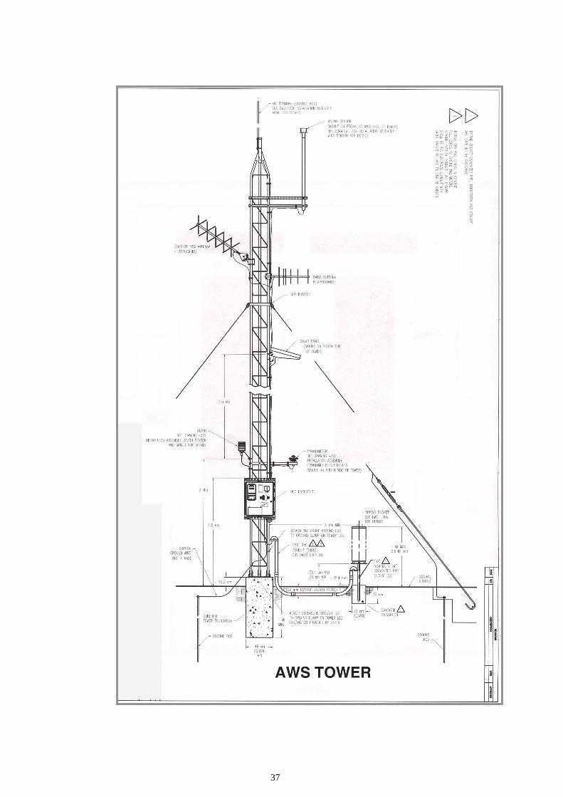
5. Tower Foundation
Dimensions: 3.5 ft x 3.5 ft (length x width) and 5 ft deep. The raised platform of the foundation must be 2.0 ft. above the ground level.
6. Rain Gauge foundation
The Rain gauge foundation must be of dimensions 1.5 ft x 1.5 ft (length x width) and 3 ft deep. The raised platform should be six inches above the ground level. The base plate of rain gauge should be 1.0 ft. above ground level. In the case of flood prone areas the base plate on which the rain gauge is mounted should be placed 1.0 metre above ground level. Such locations are to be decided based on the suggestion of respective Regional Met. Centre /Met Observatory.
7. Anchor Rod and Guy rope
The foundation for the Anchor Rod which holds the guy rope must be of dimensions 1.0 ft x 1.0 ft (length x width) at the ground level and 3 feet deep.
8. Proportions for concrete foundations
Concrete pillar foundations for the AWS tower, fencing angle, anchor rod should be made in the volumetric mixing proportions as follows:
8.1 Concrete foundation : 1 (Cement) : 2 (Sand) : 4 (Metal) 8.2 Fine plastering : 4(Cement) : 1 (Sand) 8.3 Concrete Pillar must be cemented to achieve smooth finish above the ground level. 8.4 After 8 hours, these foundations should be cured with water at least 3 times a day
for four days.
9. Local Earthing 9.1 Material required
Salt: 20 Kg, Charcoal: 20 Kg, Sand: 100 Kg
The lightning arrestor rod is made of copper which is mounted on the top most part of the ARG tower. It should be of thickness 12 mm and of one metre length with a connected copper wire of dimensions 15 metres length and 6 mm thickness (gauge). At the other end of the copper wire is the Earthing rod of dimensions 15mm thickness and 1.8 meter length, which is buried into the ground. On the bottom of Earthing rod, one copper plate of dimensions 1’ x 1’ should be connected. AWS datalogger enclosure should also be grounded with local earthing.
9.2 Procedure
A pit of 4-5 feet depth, 2’ X 2’ wide at bottom (like a cone shaped pit) has to be dug.

36
After leveling the bottom of the pit, uniform layer in the sequence of 6 inches of Salt + 6 inches Charcoal + 6 inches Sand is filled. Such sequence is repeated 3 times till the earth pit is filled to the top. The copper earthing rod is placed in the center of the pit. The pit is closed and leveled.
10. Painting
The AWS tower is painted in equal sections of alternate colours of red and white.
The fencing angles, chain-link fencing and gate should be properly painted in silver colour to avoid rusting.
All concrete foundation shall be painted using white cement.
37
38
39
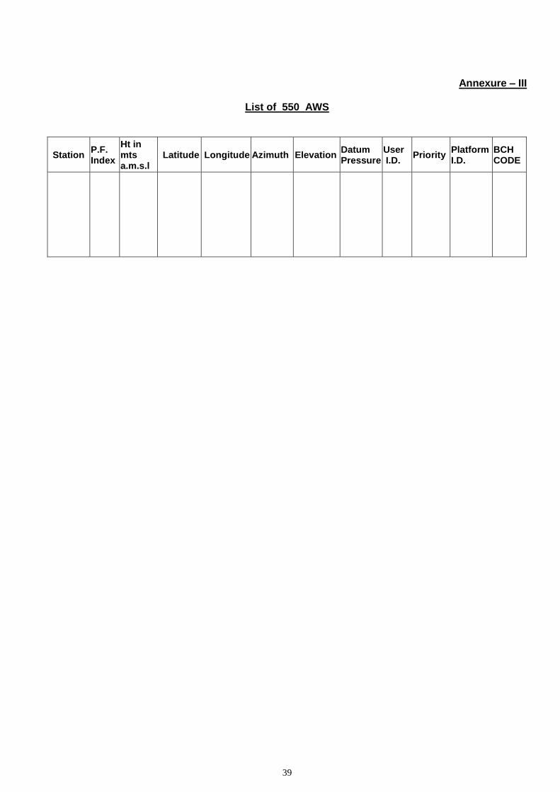
Annexure – III
List of 550 AWS
Station P.F. Index
Ht in mts a.m.s.l
Latitude Longitude Azimuth Elevation Datum Pressure
User I.D.
Priority Platform I.D.
BCH CODE
40
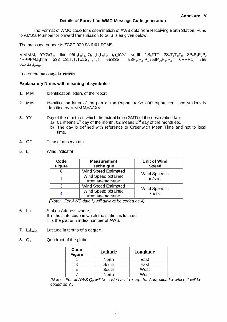
Annexure IV Details of Format for WMO Message Code generation
The Format of WMO code for dissemination of AWS data from Receiving Earth Station, Pune
to AMSS, Mumbai for onward transmission to GTS is as given below. The message header is ZCZC 000 SNIN01 DEMS MiMiMjMj YYGGiw IIiii 99LaLaLa QcL0L0L0L0 iRiXhVV Nddff 1SnTTT 2SnTdTdTd 3P0P0P0P0 4PPPP/4a3hhh 333 1SnTxTxTx/2SnTnTnTn 55SSS 58P24P24P24/59P24P24P24 6RRRtR 555 6SGSGSgSg. End of the message is NNNN Explanatory Notes with meaning of symbols:- 1. MiMi Identification letters of the report 2. MjMj Identification letter of the part of the Report. A SYNOP report from land stations is
identified by MiMiMjMj=AAXX 3. YY Day of the month on which the actual time (GMT) of the observation falls.
a) 01 means 1st day of the month, 02 means 2nd day of the month etc. b) The day is defined with reference to Greenwich Mean Time and not to local
time.
4. GG Time of observation. 5. iw Wind indicator
Code Figure
Measurement Technique
Unit of Wind Speed
0 Wind Speed Estimated Wind Speed in
m/sec. 1 Wind Speed obtained
from anemometer
3 Wind Speed Estimated Wind Speed in
knots. 4 Wind Speed obtained
from anemometer
(Note: - For AWS data iw will always be coded as 4)
6. IIiii Station Address where, II is the state code in which the station is located iii is the platform index number of AWS.
7. LaLaLa Latitude in tenths of a degree. 8. Qc Quadrant of the globe
Code Figure
Latitude Longitude
1 North East
3 South East
5 South West
7 North West
(Note: - For all AWS Qc will be coded as 1 except for Antarctica for which it will be coded as 3.)
41
9. LoLoLoLo Longitude in tenths of a degree. 10. iR Indicator for inclusion or omission of precipitation data.
Code Figure
Group 6RRRtR is
1 Included in section 1
2 Included in section 3
3 Omitted in section 1 and 3 (precipitation amount=0)
4 Omitted in section 1 and 3
(precipitation amount not available)
(Note: - For AWS data iR will always be coded as 2)
11. ix Indicator for type of station operation (manned or automatic) and for present and past weather data.
Code Figure
Type of station
operation Group 7wwW1W2 is
1 Manned Included
2 Manned Omitted (No significant phenomenon to report)
3 Manned Omitted (Not observed
data not available)
4 Automatic Included
5 Automatic Omitted (No significant phenomenon to report)
6 Automatic Omitted (Not observed
data not available)
(Note: - For AWS data ix will always be coded as 6)
12. h Height above ground of the base of the lowest cloud seen (Note: - For AWS data, h will always be coded as ‘/’)
13. VV Horizontal visibility or distance at which objects can be seen in day light (or at which lights can be seen at night) (Note: - For AWS data, VV will always be coded as ‘//’)
14. N The fraction of the sky covered by clouds of all types. (Note: - For AWS data, N will always be coded as ‘/’)
15. dd True Direction from which the surface wind blows. On the scale (01 to 36) i.e., degrees from geographic north divided by 10 and rounded off to the nearest whole number, e.g. 145 is reported as 15.
16. ff Wind Speed in knots rounded off to nearest whole number. 17. Sn Sign of temperature to be reported as zero (0) for positive temperatures or 0 °C and
one (1) for negative temperatures. 18. TTT Air temperature in tenths of a degree Celsius. 19. TdTdTd Dew point temperature in tenths of a degree Celcius. 20. P0P0P0P0 Pressure at station level in tenths of hPa, omitting thousands digit. 21. PPPP Pressure at mean sea level in tenths of hPa, omitting thousands digit.
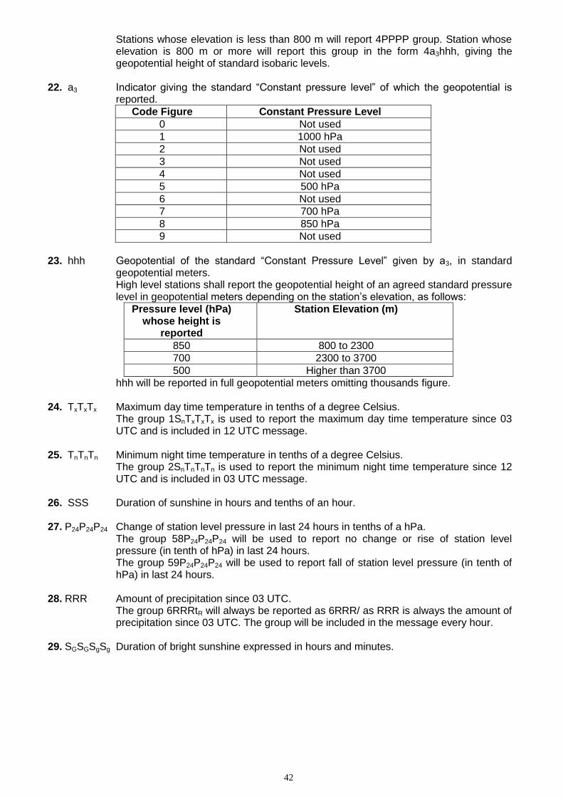
42
Stations whose elevation is less than 800 m will report 4PPPP group. Station whose elevation is 800 m or more will report this group in the form 4a3hhh, giving the geopotential height of standard isobaric levels.
22. a3 Indicator giving the standard “Constant pressure level” of which the geopotential is reported.
Code Figure Constant Pressure Level
0 Not used
1 1000 hPa
2 Not used
3 Not used
4 Not used
5 500 hPa
6 Not used
7 700 hPa
8 850 hPa
9 Not used
23. hhh Geopotential of the standard “Constant Pressure Level” given by a3, in standard
geopotential meters. High level stations shall report the geopotential height of an agreed standard pressure level in geopotential meters depending on the station’s elevation, as follows:
Pressure level (hPa) whose height is
reported
Station Elevation (m)
850 800 to 2300
700 2300 to 3700
500 Higher than 3700
hhh will be reported in full geopotential meters omitting thousands figure.
24. TxTxTx Maximum day time temperature in tenths of a degree Celsius. The group 1SnTxTxTx is used to report the maximum day time temperature since 03 UTC and is included in 12 UTC message.
25. TnTnTn Minimum night time temperature in tenths of a degree Celsius. The group 2SnTnTnTn is used to report the minimum night time temperature since 12 UTC and is included in 03 UTC message.
26. SSS Duration of sunshine in hours and tenths of an hour. 27. P24P24P24 Change of station level pressure in last 24 hours in tenths of a hPa.
The group 58P24P24P24 will be used to report no change or rise of station level pressure (in tenth of hPa) in last 24 hours. The group 59P24P24P24 will be used to report fall of station level pressure (in tenth of hPa) in last 24 hours.
28. RRR Amount of precipitation since 03 UTC.
The group 6RRRtR will always be reported as 6RRR/ as RRR is always the amount of precipitation since 03 UTC. The group will be included in the message every hour.
29. SGSGSgSg Duration of bright sunshine expressed in hours and minutes.
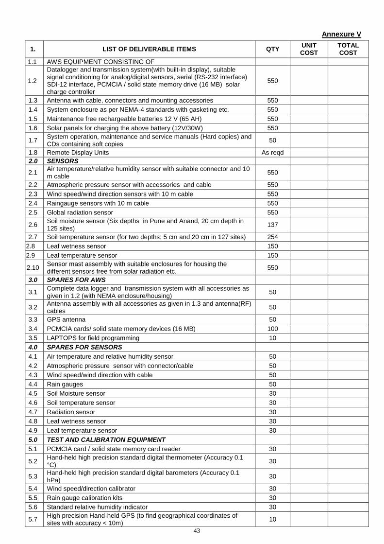
43
Annexure V
1. LIST OF DELIVERABLE ITEMS QTY UNIT COST
TOTAL COST
1.1 AWS EQUIPMENT CONSISTING OF
1.2
Datalogger and transmission system(with built-in display), suitable signal conditioning for analog/digital sensors, serial (RS-232 interface) SDI-12 interface, PCMCIA / solid state memory drive (16 MB) solar charge controller
550
1.3 Antenna with cable, connectors and mounting accessories 550
1.4 System enclosure as per NEMA-4 standards with gasketing etc. 550
1.5 Maintenance free rechargeable batteries 12 V (65 AH) 550
1.6 Solar panels for charging the above battery (12V/30W) 550
1.7 System operation, maintenance and service manuals (Hard copies) and CDs containing soft copies
50
1.8 Remote Display Units As reqd
2.0 SENSORS
2.1 Air temperature/relative humidity sensor with suitable connector and 10 m cable
550
2.2 Atmospheric pressure sensor with accessories and cable 550
2.3 Wind speed/wind direction sensors with 10 m cable 550
2.4 Raingauge sensors with 10 m cable 550
2.5 Global radiation sensor 550
2.6 Soil moisture sensor (Six depths in Pune and Anand, 20 cm depth in 125 sites)
137
2.7 Soil temperature sensor (for two depths: 5 cm and 20 cm in 127 sites) 254
2.8 Leaf wetness sensor 150
2.9 Leaf temperature sensor 150
2.10 Sensor mast assembly with suitable enclosures for housing the different sensors free from solar radiation etc.
550
3.0 SPARES FOR AWS
3.1 Complete data logger and transmission system with all accessories as given in 1.2 (with NEMA enclosure/housing)
50
3.2 Antenna assembly with all accessories as given in 1.3 and antenna(RF) cables
50
3.3 GPS antenna 50
3.4 PCMCIA cards/ solid state memory devices (16 MB) 100
3.5 LAPTOPS for field programming 10
4.0 SPARES FOR SENSORS
4.1 Air temperature and relative humidity sensor 50
4.2 Atmospheric pressure sensor with connector/cable 50
4.3 Wind speed/wind direction with cable 50
4.4 Rain gauges 50
4.5 Soil Moisture sensor 30
4.6 Soil temperature sensor 30
4.7 Radiation sensor 30
4.8 Leaf wetness sensor 30
4.9 Leaf temperature sensor 30
5.0 TEST AND CALIBRATION EQUIPMENT
5.1 PCMCIA card / solid state memory card reader 30
5.2 Hand-held high precision standard digital thermometer (Accuracy 0.1 °C)
30
5.3 Hand-held high precision standard digital barometers (Accuracy 0.1 hPa)
30
5.4 Wind speed/direction calibrator 30
5.5 Rain gauge calibration kits 30
5.6 Standard relative humidity indicator 30
5.7 High precision Hand-held GPS (to find geographical coordinates of sites with accuracy < 10m)
10
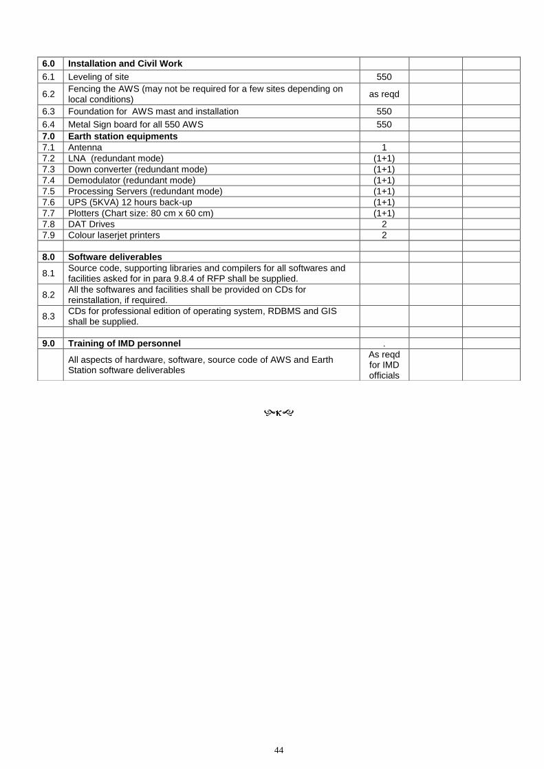
44
6.0 Installation and Civil Work
6.1 Leveling of site 550
6.2 Fencing the AWS (may not be required for a few sites depending on local conditions)
as reqd
6.3 Foundation for AWS mast and installation 550
6.4 Metal Sign board for all 550 AWS 550
7.0 Earth station equipments
7.1 Antenna 1
7.2 LNA (redundant mode) (1+1)
7.3 Down converter (redundant mode) (1+1)
7.4 Demodulator (redundant mode) (1+1)
7.5 Processing Servers (redundant mode) (1+1)
7.6 UPS (5KVA) 12 hours back-up (1+1)
7.7 Plotters (Chart size: 80 cm x 60 cm) (1+1)
7.8 DAT Drives 2
7.9 Colour laserjet printers 2
8.0 Software deliverables
8.1 Source code, supporting libraries and compilers for all softwares and facilities asked for in para 9.8.4 of RFP shall be supplied.
8.2 All the softwares and facilities shall be provided on CDs for reinstallation, if required.
8.3 CDs for professional edition of operating system, RDBMS and GIS shall be supplied.
9.0 Training of IMD personnel .
All aspects of hardware, software, source code of AWS and Earth Station software deliverables
As reqd for IMD officials