product catalog€¦ · · 2018-03-03cg-prc019-e4 aquastream 3g™ air-cooled liquid chillers...
TRANSCRIPT
CG-PRC019-E4
AquaStream 3G™ Air-Cooled Liquid ChillersModel CGAM
Product Catalog
© 2009 Trane All rights reserved CG-PRC019-EN
Introduction
Design and manufacturing excellence makes Trane a leader in the air-cooled chiller marketplace.
This tradition of using excellence to meet market demands is illustrated with the new Trane
AquaStream 3G the 55-450 kW air-cooled cooling unit. The introduction of this next-generation
chiller is an exciting step forward in energy-efficiency, sound, reliability, ease of serviceability,
control precision, application versatility, and operational cost-effectiveness. The new chiller is
designed to deliver proven AquaStream 3G performance based on the redesign of a European
model that has been a market leader, plus all the benefits of new heat transfer and fan designs, as
well as, low-speed, direct-drive scroll compressors.
Important Design Advances and New Features
• Higher full-load and part-load energy efficiency that reduce operating costs.
• Significantly lower noise levels than other scroll compressor chillers.
• HFC-410A optimized design.
• Factory-installed evaporator pump and buffer tank available to make installation easier.
• Flow switch and water strainer are factory installed in the optimum locations for seamless
operation and reduced chiller installation and maintenance time.
• Trane CH530™ with Adaptive Controls™ have improved fan algorithms for more reliable
operation at extreme conditions.
• Single chiller time of day scheduling communication for easier control of small jobs.
• Easily integrated with existing BAS via BACnet™, Modbus™, or LonTalk™ communication
interface.
• All major service components are close to the unit edge for safe and easy maintenance.
• The chiller is designed for easy serviceability with input from our extended experience in
design, testing and field operation.
Table of Contents
CG-PRC019-EN 3
Features and Benefits . . . . . . . . . . . . . . . . . . . . . . . . . . . . . . . . . . . . . . . . . . . . . . . . . . . 4
Application Considerations . . . . . . . . . . . . . . . . . . . . . . . . . . . . . . . . . . . . . . . . . . . . . . 7
Model Number Descriptions . . . . . . . . . . . . . . . . . . . . . . . . . . . . . . . . . . . . . . . . . . . . 16
General Data . . . . . . . . . . . . . . . . . . . . . . . . . . . . . . . . . . . . . . . . . . . . . . . . . . . . . . . . . . 18
Controls . . . . . . . . . . . . . . . . . . . . . . . . . . . . . . . . . . . . . . . . . . . . . . . . . . . . . . . . . . . . . . 54
Dimensions . . . . . . . . . . . . . . . . . . . . . . . . . . . . . . . . . . . . . . . . . . . . . . . . . . . . . . . . . . . 60
Mechanical Specifications . . . . . . . . . . . . . . . . . . . . . . . . . . . . . . . . . . . . . . . . . . . . . . 66
Options . . . . . . . . . . . . . . . . . . . . . . . . . . . . . . . . . . . . . . . . . . . . . . . . . . . . . . . . . . . . . . . 69
Hydraulic Data . . . . . . . . . . . . . . . . . . . . . . . . . . . . . . . . . . . . . . . . . . . . . . . . . . . . . . . . 74
Operating Map . . . . . . . . . . . . . . . . . . . . . . . . . . . . . . . . . . . . . . . . . . . . . . . . . . . . . . . . 80
Unit Schematics . . . . . . . . . . . . . . . . . . . . . . . . . . . . . . . . . . . . . . . . . . . . . . . . . . . . . . . 81
4 CG-PRC019-E4
Features and Benefits
Reliability
• Years of laboratory testing including running the chiller at extreme operating conditions have
resulted in optimized compressor and chiller systems reliability by confirming a robust design
and verifying quality each step of the way.
• Direct-drive, low-speed scroll compressors with fewer moving parts provide maximum
efficiency, high reliability, and low maintenance requirements. Suction gas-cooled motor stays
at a uniformly low temperature for long motor life.
• The third generation microprocessor control system provides improved control capabilities
with Adaptive Control™ to keep the unit operating even in adverse conditions. Advanced
microelectronics protect both the compressor and the motor from typical electrical fault
conditions like thermal overload and phase rotation.
• Flow switch is factory-installed at the optimum location in the piping for reduced chiller
installation cost and superior flow sensing, reducing the potential for nuisance trips.
• Exceptionally rigid condenser coil structure is designed with finished element analysis.
• Innovative condenser pressure integrated fan control algorithms provide more reliable
operation at extreme temperature conditions.
Life Cycle Cost-Effectiveness
• Industry leading full- and part-load efficiency
• Electronic expansion valve and high speed suction temperature sensor enables tight chilled
water temperature control and low superheat, resulting in more efficient full-load and part-load
operation than previously available.
• The factory-installed and tested pump package available with many options to meet a variety
of customer needs.
CG-PRC019-E4 5
Features and Benefits
Application Versatility
• Industrial/low temperature process cooling - Excellent operating temperature range and
precise control capabilities enable tight control.
• Ice/thermal storage - Utilities and owners benefit from reduced cooling energy cost. The
AquaStream 3G chiller’s dual setpoint control and industry leading ice energy storage
efficiency assures reliable operation and superior system efficiency.
Simple, Economical Installation
• There are a variety of sound options to help meet many different job site requirements:
compact, super quiet and comprehensive acoustic package.
• System integration available with LonTalk, or ModBus, or BACnet through a single twisted-pair
wire for a less expensive translation to an existing building automation system.
• Powder-coated paint provides superior durability, corrosion protection, and is less likely to be
damaged while rigging/lifting/installing the chiller.
• Factory commissioned unit-mounted starter reduces overall job cost and improves system
reliability by eliminating job site design, installation and labor coordination requirements.
Precision Control
• Microprocessor-based Trane CH530 controls monitor and maintain optimal operation of the
chiller and its associated sensors, actuators, relays, and switches, all of which are factory-
installed, powered up and tested prior to shipping.
• Adaptive Control maintains chiller operation under adverse conditions, when many other
chillers might simply shut down. Operating conditions that are compensated for include high
condensing pressure and low suction pressure.
6 CG-PRC019-E4
Features and Benefits
• AquaStream 3G advanced microprocessor controls enable variable primary flow applications
providing chilled water temperature control accuracy of ±2°F (1.1°C) for flow changes up to 10
percent per minute, plus handling of flow changes up to 30 percent per minute with continuous
operation.
• Easy-to-use operator interface displays all operating and safety messages, with complete
diagnostics information, on a highly readable panel with a scrolling touch-screen display.
Status and diagnostic messages are in plain language - no codes to interpret - and are available
in 20 languages.
Improved Serviceability
• All major serviceable components are close to the edge. Service shutoff valves and water
strainer are conveniently located to enable easy service.
• Water piping connections are factory piped to the edge of the unit to make installation safer and
faster.
• Electronic expansion valve designed so controls can be removed and serviced without
refrigerant handling.
• The optional pump package is designed to be serviced in place. The unit structure includes a
rigging point for pump servicing, making inspection, cleaning and pump seal changes easier.
• High pressure transducer and temperature sensors mountings enable troubleshooting and
replacement without removing refrigerant charge, greatly improving serviceability over the life
of the unit.
• Dead front panel construction provides for enhanced service technician safety.
CG-PRC019-E4 7
Application Considerations
Certain application constraints should be considered when sizing, selecting and installing Trane
AquaStream 3G chillers. Unit and system reliability is often dependent upon proper and complete
compliance with these considerations. Where the application varies from the guidelines presented,
it should be reviewed with your local Trane sales engineer.
Note: The terms water and solution are used interchangeably in the following paragraphs.
Unit Sizing
Intentionally over-sizing a unit to assure adequate capacity is not recommended. Erratic system
operation and excessive compressor cycling are often a direct result of an oversized chiller. In
addition, an oversized unit is usually more expensive to purchase, install, and operate. If over sizing
is desired consider using two smaller units.
Water Treatment
The use of untreated or improperly treated water in chillers may result in scaling, erosion,
corrosion, and algae or slime buildup. This will adversely affect heat transfer between the water
and system components. Proper water treatment must be determined locally and depends on the
type of system and local water characteristics.
Neither salt nor brackish water is recommend for use in Trane air-cooled AquaStream 3G chillers.
Use of either will lead to a shortened life. Trane encourages the employment of a qualified water
treatment specialist, familiar with local water conditions, to assist in the establishment of a proper
water treatment program.
Foreign matter in the chilled water system can also increase pressure drop and, consequently,
reduce water flow. For this reason it is important to thoroughly flush all water piping to the unit
before making the final piping connections to the unit.
Effect of Altitude on Capacity
At elevations substantially above sea level, the decreased air density will decrease condenser
capacity and, therefore, unit capacity and efficiency.
8 CG-PRC019-E4
Application Considerations
Ambient Limitations
Trane AquaStream 3G chillers are designed for year-round operation over a range of ambient
temperatures. The air-cooled model CGAM chiller will operate in ambient temperatures of 46°C.
Selecting the low ambient option will allow the chiller to operate with ambient temperature as low
as -18°C and high ambient option will increase the operational capability of the chiller to operate
in ambient temperatures up to 52°C.
The minimum ambient temperatures are based on still conditions (winds not exceeding 8 km/h).
Greater wind velocities will result in a drop in head pressure, therefore increasing the minimum
starting and operating ambient temperature. The Adaptive Control™ microprocessor will attempt
to keep the chiller on-line when high or low ambient conditions exist, making every effort to avoid
nuisance trip-outs and provide the maximum allowable tonnage.
Water Flow Limits
The minimum water flow rates are given in the General Data section of this catalog. Evaporator
flow rates below the tabulated values will result in laminar flow causing freeze-up problems,
scaling, stratification and poor control. The maximum evaporator water flow rate is also given.
Flow rates exceeding those listed may result in very high pressure drop across the evaporator.
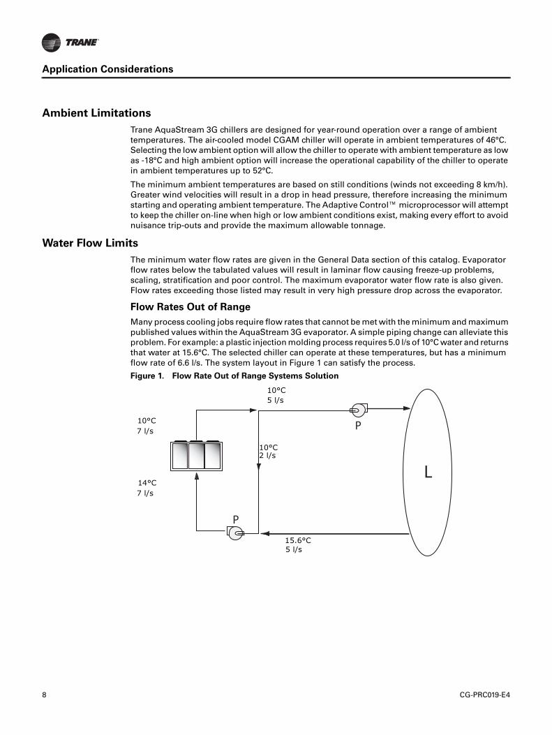
Flow Rates Out of Range
Many process cooling jobs require flow rates that cannot be met with the minimum and maximum
published values within the AquaStream 3G evaporator. A simple piping change can alleviate this
problem. For example: a plastic injection molding process requires 5.0 l/s of 10°C water and returns
that water at 15.6°C. The selected chiller can operate at these temperatures, but has a minimum
flow rate of 6.6 l/s. The system layout in Figure 1 can satisfy the process.
Figure 1. Flow Rate Out of Range Systems Solution
10°C
7 l/s
10°C
5 l/s
15.6°C
5 l/s
10°C2 l/s
14°C
7 l/s
CG-PRC019-E4 9
Application Considerations
Flow Proving
Trane provides a factory-installed water flow switch monitored by CH530 which protects the chiller
from operating in loss of flow conditions.
Variable Flow in the Evaporator
An attractive chilled water system option may be a Variable Primary Flow (VPF) system. VPF
systems present building owners with several cost-saving benefits when compared with Primary/
Secondary chilled water systems. The most obvious cost savings results from eliminating the
constant volume chiller pump(s), which in turn eliminates the related expenses of the associated
piping connections (material, labor), and electrical service and switch gear. In addition to the
installed cost advantage building owners often cite pump related energy savings as the reasons
that prompted them to select a VPF system.
The AquaStream 3G has the capability to handle variable evaporator flow without losing leaving
water temperature control. The microprocessor and capacity control algorithms are designed to
take a 10 percent change in water flow rate per minute while maintaining a ±1.1°C leaving water
temperature control accuracy. The chiller tolerates up to 30 percent per minute water flow variation
as long as the flow is equal or above the minimum flow rate requirement.
With the help of a software analysis tool such as System Analyzer™, DOE-2 or TRACE™, you can
determine whether the anticipated energy savings justify the use of variable primary flow in a
particular application. Existing constant flow chilled water systems may be relatively easily
converted to VPF and benefit greatly from the inherent efficiency advantages.
Water Temperature
Leaving Water Temperature Limits
Trane AquaStream 3G chillers have three distinct leaving water categories:
• standard, with a leaving solution range of 5.5 to 18°C
• low temperature process cooling, with leaving solution range of -12 to 18°C
• ice-making, with leaving solution range of -7 to 18°C
Since leaving solution temperature below 5.5°C results in suction temperature at or below the
freezing point of water, a glycol solution is required for all low temperature and ice-making
machines. Ice making control includes dual setpoint controls and safeties for ice making and
standard cooling capabilities. Consult your local Trane sales engineer for applications or selections
involving low temperature or ice making machines.
The maximum water temperature that can be circulated through the CGAM evaporator when the
unit is not operating is 51.7°C.
10 CG-PRC019-E4
Application Considerations
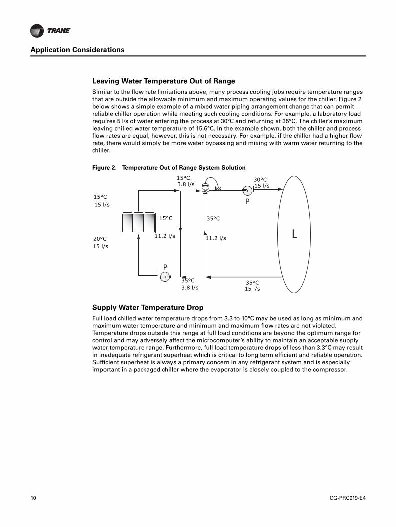
Leaving Water Temperature Out of Range
Similar to the flow rate limitations above, many process cooling jobs require temperature ranges
that are outside the allowable minimum and maximum operating values for the chiller. Figure 2
below shows a simple example of a mixed water piping arrangement change that can permit
reliable chiller operation while meeting such cooling conditions. For example, a laboratory load
requires 5 l/s of water entering the process at 30°C and returning at 35°C. The chiller’s maximum
leaving chilled water temperature of 15.6°C. In the example shown, both the chiller and process
flow rates are equal, however, this is not necessary. For example, if the chiller had a higher flow
rate, there would simply be more water bypassing and mixing with warm water returning to the
chiller.
Supply Water Temperature Drop
Full load chilled water temperature drops from 3.3 to 10°C may be used as long as minimum and
maximum water temperature and minimum and maximum flow rates are not violated.
Temperature drops outside this range at full load conditions are beyond the optimum range for
control and may adversely affect the microcomputer’s ability to maintain an acceptable supply
water temperature range. Furthermore, full load temperature drops of less than 3.3°C may result
in inadequate refrigerant superheat which is critical to long term efficient and reliable operation.
Sufficient superheat is always a primary concern in any refrigerant system and is especially
important in a packaged chiller where the evaporator is closely coupled to the compressor.
Figure 2. Temperature Out of Range System Solution
L
P
P
15°C 30°C15 l/s
35°C
11.2 l/s
35°C15 l/s
35°C
3.8 l/s
15°C
11.2 l/s20°C
15 l/s
3.8 l/s
15 l/s
15°C
CG-PRC019-E4 11
Application Considerations
Parameters which influence the water temperature stability:
• Ambient temperature and water temperature (modify cooling capacity)
• Number of capacity steps
• Minimum time between starts of a compressor
• Control dead band
• Water loop volume
• Load fluctuations
• Fluid type or percentage of glycol
Typical Water Piping
All building water piping must be flushed prior to making final connections to the chiller. To reduce
heat loss and prevent condensation, insulation should be applied. Expansion tanks are also usually
required so that chilled water volume changes can be accommodated.
Avoidance of Short Water Loops
Adequate chilled water system water volume is an important system design parameter because it
provides for stable chilled water temperature control and helps limit unacceptable short cycling of
chiller compressors.
The AquaStream 3G chiller’s temperature control sensor is located in the supply (outlet) water
connection or pipe. This location allows the building to act as a buffer to slow the rate of change
of the system water temperature. If there is not a sufficient volume of water in the system to provide
an adequate buffer, temperature control can suffer, resulting in erratic system operation and
excessive compressor cycling.
Typically, a two-minute water loop circulation time is sufficient to prevent short water loop issues.
Therefore, as a guideline, ensure the volume of water in the chilled water loop equals or exceeds
two times the evaporator flow rate. For systems with a rapidly changing load profile the amount
of volume should be increased.
If the installed system volume does not meet the above recommendations, the following items
should be given careful consideration to increase the volume of water in the system and, therefore,
reduce the rate of change of the return water temperature.
• A volume buffer tank located in the return water piping.
• Larger system supply and return header piping (which also reduces system pressure drop and
pump energy use).
12 CG-PRC019-E4
Application Considerations
An optional factory-installed buffer tank is designed to meet the minimum two minute loop time
without additional job site piping. The buffer tank can also be used on jobs that already meet or
exceed the minimum loop time to further reduce the potential for compressor cycling, increasing
the compressor life span, and reducing system temperature fluctuations.
Minimum water volume for a process application
If a chiller is attached to an on/off load such as a process load, it may be difficult for the controller
to respond quickly enough to the very rapid change in return solution temperature if the system
has only the minimum water volume recommended. Such systems may cause chiller low
temperature safety trips or in the extreme case evaporator freezing. In this case, it may be
necessary to add or increase the size of the mixing tank in the return line or consider the optional
factory-installed buffer tank with the chiller.
Multiple Unit Operation
Whenever two or more units are used on one chilled water loop, Trane recommends that their
operation be coordinated with a higher level system controller for best system efficiency and
reliability. The Trane Tracer system has advanced chilled plant control capabilities designed to
provide such operation.
Ice Storage Operation
An ice storage system uses the chiller to make ice at night when utilities generate electricity more
efficiently and charge less for electricity with lower demand and energy charges. The stored ice
reduces or even replaces mechanical cooling during the day when utility rates are at their highest.
This reduced need for cooling results in significant utility cost savings and source energy savings.
Another advantage of an ice storage system is its ability to eliminate chiller over sizing. A
“rightsized” chiller plant with ice storage operates more efficiently with smaller support equipment
while lowering the connected load and reducing operating costs. Best of all this system still
provides a capacity safety factor and redundancy by building it into the ice storage capacity for
practically no cost compared to over sized systems.
The Trane air-cooled chiller is uniquely suited to low temperature applications like ice storage
because of the ambient relief experienced at night. Chiller ice making efficiencies are typically
similar to or even better than standard cooling daytime efficiencies as a result of night-time dry-
bulb ambient relief.
Standard smart control strategies for ice storage systems are another advantage of the
AquaStream 3G chiller. The dual mode control functionality are integrated right into the chiller.
Trane Tracer building management systems can measure demand and receive pricing signals from
the utility and decide when to use the stored cooling and when to use the chiller.
CG-PRC019-E4 13
Application Considerations
Unit Placement
Setting The Unit
A base or foundation is not required if the selected unit location is level and strong enough to
support the unit’s operating weight (see “Weights” section of this catalog).
For a detailed discussion of base and foundation construction, refer to the sound engineering
bulletin or the unit IOM. Manuals are available through the local Trane office.
HVAC equipment must be located to minimize sound and vibration transmission to the occupied
spaces of the building structure it serves. If the equipment must be located in close proximity to
a building, it should be placed next to an unoccupied space such as a storage room, mechanical
room, etc. It is not recommended to locate the equipment near occupied, sound sensitive areas of
the building or near windows. Locating the equipment away from structures will also prevent
sound reflection, which can increase sound levels at property lines or other sensitive points.
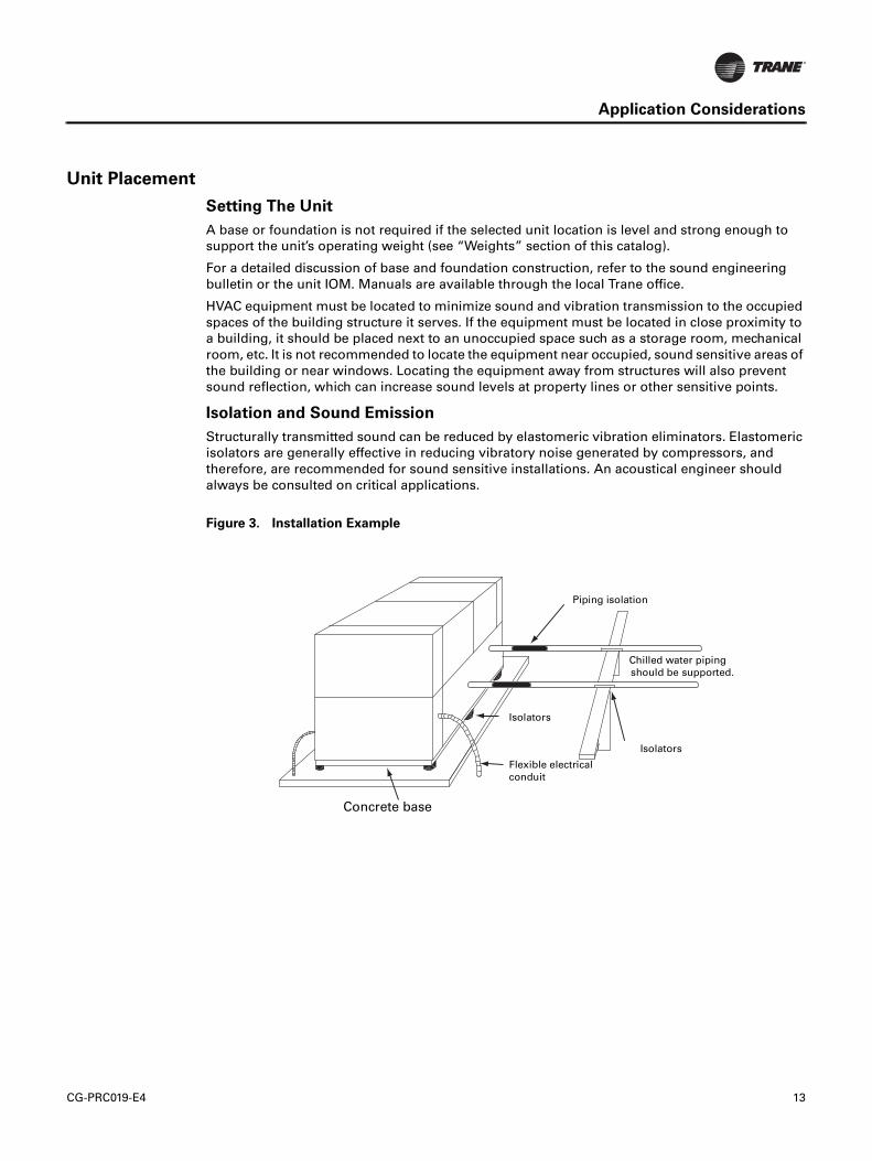
Isolation and Sound Emission
Structurally transmitted sound can be reduced by elastomeric vibration eliminators. Elastomeric
isolators are generally effective in reducing vibratory noise generated by compressors, and
therefore, are recommended for sound sensitive installations. An acoustical engineer should
always be consulted on critical applications.
Figure 3. Installation Example
Flexible electrical
conduit
Chilled water piping
Isolators
Piping isolation
Concrete base
Isolators
supported.should be
14 CG-PRC019-E4
Application Considerations
For maximum isolation effect, water lines and electrical conduit should also be isolated. Wall
sleeves and rubber isolated piping hangers can be used to reduce the sound transmitted through
water piping. To reduce the sound transmitted through electrical conduit, use flexible electrical
conduit.
Local codes on sound emissions should always be considered. Since the environment in which a
sound source is located affects sound pressure, unit placement must be carefully evaluated. Sound
power levels for chillers are available on request.
Servicing
Adequate clearance for evaporator and compressor servicing should be provided. Recommended
minimum space envelopes for servicing are located in the dimensional data section and can serve
as a guideline for providing adequate clearance. The minimum space envelopes also allow for
control panel door swing and routine maintenance requirements. Local code requirements may
take precedence.
Unit Location
General
Unobstructed flow of condenser air is essential to maintain chiller capacity and operating
efficiency. When determining unit placement, careful consideration must be given to assure a
sufficient flow of air across the condenser heat transfer surface. Two detrimental conditions are
possible and must be avoided: warm air recirculation and coil starvation. Air recirculation occurs
when discharge air from the condenser fans is recycled back to the condenser coil inlet. Coil
starvation occurs when free airflow to the condenser is restricted.
Condenser coils and fan discharge must be kept free of snow or other obstructions to permit
adequate airflow for satisfactory unit operation. Debris, trash, supplies, etc., should not be allowed
to accumulate in the vicinity of the air-cooled chiller. Supply air movement may draw debris into
the condenser coil, blocking spaces between coil fins and causing coil starvation.
CG-PRC019-E4 15
Application Considerations
Both warm air recirculation and coil starvation cause reductions in unit efficiency and capacity
because of the higher head pressures associated with them. The air-cooled AquaStream 3G chiller
offers an advantage over competitive equipment in these situations. Operation is minimally
affected in many restricted air flow situations due to its advanced Adaptive Control™
microprocessor which has the ability to understand the operating environment of the chiller and
adapt to it by first optimizing its performance and then staying on line through abnormal
conditions. For example, high ambient temperatures combined with a restricted air flow situation
will generally not cause the air-cooled model CGAM chiller to shut down. Other chillers would
typically shut down on a high pressure nuisance cut-out in these conditions.
Cross winds, those perpendicular to the condenser, tend to aid efficient operation in warmer
ambient conditions. However, they tend to be detrimental to operation in lower ambients due to
the accompanying loss of adequate head pressure. Special consideration should be given to low
ambient units. As a result, it is advisable to protect air-cooled chillers from continuous direct winds
exceeding 4.5 m/s in low ambient conditions.
The recommended lateral clearances are depicted in the close spacing engineering bulletin
available from your local office.
Provide Sufficient Unit-to-Unit Clearance
Units should be separated from each other by sufficient distance to prevent warm air recirculation
or coil starvation. Doubling the recommended single unit air-cooled chiller clearances will
generally prove to be adequate.
Walled Enclosure Installations
When the unit is placed in an enclosure or small depression, the top of the surrounding walls
should be no higher than the top of the fans. The chiller should be completely open above the fan
deck. There should be no roof or structure covering the top of the chiller. Ducting individual fans
is not recommended.
16 CG-PRC019-E4
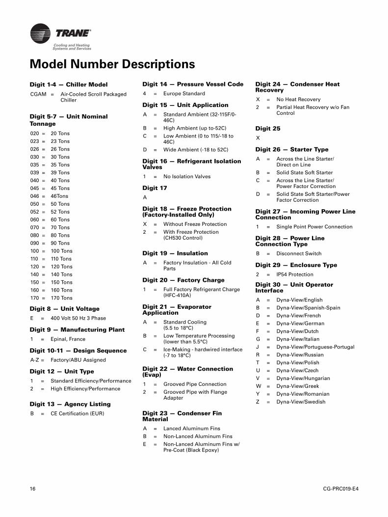
Digit 1-4 — Chiller Model
Digit 5-7 — Unit Nominal
Tonnage
Digit 8 — Unit Voltage
Digit 9 — Manufacturing Plant
Digit 10-11 — Design Sequence
Digit 12 — Unit Type
Digit 13 — Agency Listing
CGAM = Air-Cooled Scroll Packaged Chiller
020 = 20 Tons
023 = 23 Tons
026 = 26 Tons
030 = 30 Tons
035 = 35 Tons
039 = 39 Tons
040 = 40 Tons
045 = 45 Tons
046 = 46Tons
050 = 50 Tons
052 = 52 Tons
060 = 60 Tons
070 = 70 Tons
080 = 80 Tons
090 = 90 Tons
100 = 100 Tons
110 = 110 Tons
120 = 120 Tons
140 = 140 Tons
150 = 150 Tons
160 = 160 Tons
170 = 170 Tons
E = 400 Volt 50 Hz 3 Phase
1 = Epinal, France
A-Z = Factory/ABU Assigned
1 = Standard Efficiency/Performance
2 = High Efficiency/Performance
B = CE Certification (EUR)
Digit 14 — Pressure Vessel Code
Digit 15 — Unit Application
Digit 16 — Refrigerant Isolation Valves
Digit 17
Digit 18 — Freeze Protection (Factory-Installed Only)
Digit 19 — Insulation
Digit 20 — Factory Charge
Digit 21 — Evaporator Application
Digit 22 — Water Connection (Evap)
Digit 23 — Condenser Fin Material
4 = Europe Standard
A = Standard Ambient (32-115F/0-46C)
B = High Ambient (up to-52C)
C = Low Ambient (0 to 115/-18 to 46C)
D = Wide Ambient (-18 to 52C)
1 = No Isolation Valves
A
X = Without Freeze Protection
2 = With Freeze Protection (CH530 Control)
A = Factory Insulation - All Cold Parts
1 = Full Factory Refrigerant Charge (HFC-410A)
A = Standard Cooling (5.5 to 18°C)
B = Low Temperature Processing(lower than 5.5°C)
C = Ice-Making - hardwired interface (-7 to 18°C)
1 = Grooved Pipe Connection
2 = Grooved Pipe with Flange Adapter
A = Lanced Aluminum Fins
B = Non-Lanced Aluminum Fins
E = Non-Lanced Aluminum Fins w/ Pre-Coat (Black Epoxy)
Digit 24 — Condenser Heat Recovery
Digit 25
Digit 26 — Starter Type
Digit 27 — Incoming Power Line Connection
Digit 28 — Power Line Connection Type
Digit 29 — Enclosure Type
Digit 30 — Unit Operator Interface
X = No Heat Recovery
2 = Partial Heat Recovery w/o Fan Control
X
A = Across the Line Starter/Direct on Line
B = Solid State Soft Starter
C = Across the Line Starter/Power Factor Correction
D = Solid State Soft Starter/Power Factor Correction
1 = Single Point Power Connection
B = Disconnect Switch
2 = IP54 Protection
A = Dyna-View/English
B = Dyna-View/Spanish-Spain
D = Dyna-View/French
E = Dyna-View/German
F = Dyna-View/Dutch
G = Dyna-View/Italian
J = Dyna-View/Portuguese-Portugal
R = Dyna-View/Russian
T = Dyna-View/Polish
U = Dyna-View/Czech
V = Dyna-View/Hungarian
W = Dyna-View/Greek
Y = Dyna-View/Romanian
Z = Dyna-View/Swedish
Model Number Descriptions
CG-PRC019-E4 17
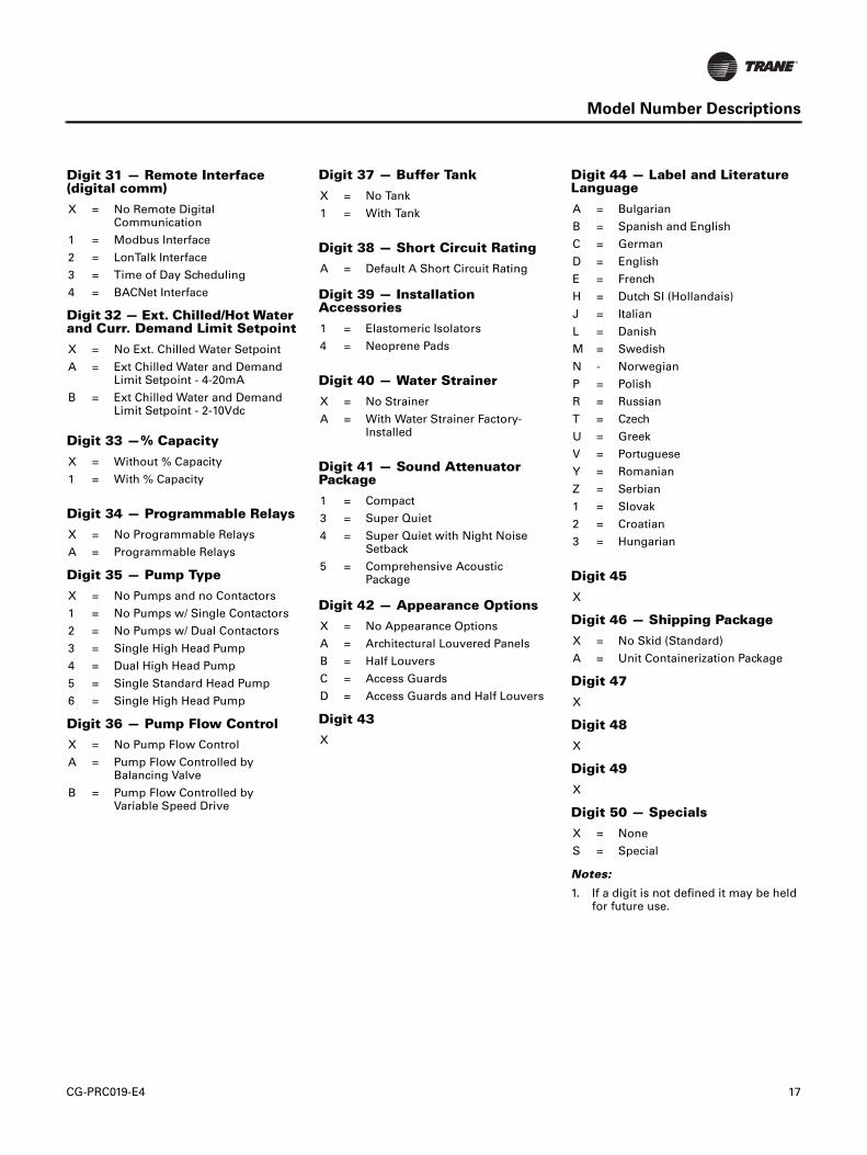
Model Number Descriptions
Digit 31 — Remote Interface (digital comm)
Digit 32 — Ext. Chilled/Hot Water and Curr. Demand Limit Setpoint
Digit 33 —% Capacity
Digit 34 — Programmable Relays
Digit 35 — Pump Type
Digit 36 — Pump Flow Control
X = No Remote Digital Communication
1 = Modbus Interface
2 = LonTalk Interface
3 = Time of Day Scheduling
4 = BACNet Interface
X = No Ext. Chilled Water Setpoint
A = Ext Chilled Water and Demand Limit Setpoint - 4-20mA
B = Ext Chilled Water and Demand Limit Setpoint - 2-10Vdc
X = Without % Capacity
1 = With % Capacity
X = No Programmable Relays
A = Programmable Relays
X = No Pumps and no Contactors
1 = No Pumps w/ Single Contactors
2 = No Pumps w/ Dual Contactors
3 = Single High Head Pump
4 = Dual High Head Pump
5 = Single Standard Head Pump
6 = Single High Head Pump
X = No Pump Flow Control
A = Pump Flow Controlled by Balancing Valve
B = Pump Flow Controlled by Variable Speed Drive
Digit 37 — Buffer Tank
Digit 38 — Short Circuit Rating
Digit 39 — Installation Accessories
Digit 40 — Water Strainer
Digit 41 — Sound Attenuator Package
Digit 42 — Appearance Options
Digit 43
X = No Tank
1 = With Tank
A = Default A Short Circuit Rating
1 = Elastomeric Isolators
4 = Neoprene Pads
X = No Strainer
A = With Water Strainer Factory- Installed
1 = Compact
3 = Super Quiet
4 = Super Quiet with Night Noise Setback
5 = Comprehensive Acoustic Package
X = No Appearance Options
A = Architectural Louvered Panels
B = Half Louvers
C = Access Guards
D = Access Guards and Half Louvers
X
Digit 44 — Label and Literature Language
Digit 45
Digit 46 — Shipping Package
Digit 47
Digit 48
Digit 49
Digit 50 — Specials
Notes:
1. If a digit is not defined it may be held for future use.
A = Bulgarian
B = Spanish and English
C = German
D = English
E = French
H = Dutch SI (Hollandais)
J = Italian
L = Danish
M = Swedish
N - Norwegian
P = Polish
R = Russian
T = Czech
U = Greek
V = Portuguese
Y = Romanian
Z = Serbian
1 = Slovak
2 = Croatian
3 = Hungarian
X
X = No Skid (Standard)
A = Unit Containerization Package
X
X
X
X = None
S = Special
18 CG-PRC019-E4
General Data
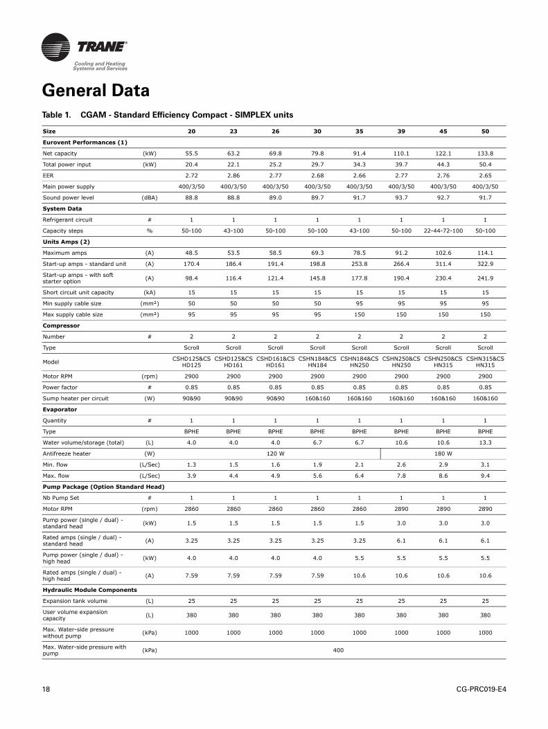
Table 1. CGAM - Standard Efficiency Compact - SIMPLEX units
Size 20 23 26 30 35 39 45 50
Eurovent Performances (1)
Net capacity (kW) 55.5 63.2 69.8 79.8 91.4 110.1 122.1 133.8
Total power input (kW) 20.4 22.1 25.2 29.7 34.3 39.7 44.3 50.4
EER 2.72 2.86 2.77 2.68 2.66 2.77 2.76 2.65
Main power supply 400/3/50 400/3/50 400/3/50 400/3/50 400/3/50 400/3/50 400/3/50 400/3/50
Sound power level (dBA) 88.8 88.8 89.0 89.7 91.7 93.7 92.7 91.7
System Data
Refrigerant circuit # 1 1 1 1 1 1 1 1
Capacity steps % 50-100 43-100 50-100 50-100 43-100 50-100 22-44-72-100 50-100
Units Amps (2)
Maximum amps (A) 48.5 53.5 58.5 69.3 78.5 91.2 102.6 114.1
Start-up amps - standard unit (A) 170.4 186.4 191.4 198.8 253.8 266.4 311.4 322.9
Start-up amps - with soft starter option
(A) 98.4 116.4 121.4 145.8 177.8 190.4 230.4 241.9
Short circuit unit capacity (kA) 15 15 15 15 15 15 15 15
Min supply cable size (mm²) 50 50 50 50 95 95 95 95
Max supply cable size (mm²) 95 95 95 95 150 150 150 150
Compressor
Number # 2 2 2 2 2 2 2 2
Type Scroll Scroll Scroll Scroll Scroll Scroll Scroll Scroll
ModelCSHD125&CS
HD125CSHD125&CS
HD161CSHD161&CS
HD161CSHN184&CS
HN184CSHN184&CS
HN250CSHN250&CS
HN250CSHN250&CS
HN315CSHN315&CS
HN315
Motor RPM (rpm) 2900 2900 2900 2900 2900 2900 2900 2900
Power factor # 0.85 0.85 0.85 0.85 0.85 0.85 0.85 0.85
Sump heater per circuit (W) 90&90 90&90 90&90 160&160 160&160 160&160 160&160 160&160
Evaporator
Quantity # 1 1 1 1 1 1 1 1
Type BPHE BPHE BPHE BPHE BPHE BPHE BPHE BPHE
Water volume/storage (total) (L) 4.0 4.0 4.0 6.7 6.7 10.6 10.6 13.3
Antifreeze heater (W) 120 W 180 W
Min. flow (L/Sec) 1.3 1.5 1.6 1.9 2.1 2.6 2.9 3.1
Max. flow (L/Sec) 3.9 4.4 4.9 5.6 6.4 7.8 8.6 9.4
Pump Package (Option Standard Head)
Nb Pump Set # 1 1 1 1 1 1 1 1
Motor RPM (rpm) 2860 2860 2860 2860 2860 2890 2890 2890
Pump power (single / dual) - standard head
(kW) 1.5 1.5 1.5 1.5 1.5 3.0 3.0 3.0
Rated amps (single / dual) - standard head
(A) 3.25 3.25 3.25 3.25 3.25 6.1 6.1 6.1
Pump power (single / dual) - high head
(kW) 4.0 4.0 4.0 4.0 5.5 5.5 5.5 5.5
Rated amps (single / dual) - high head
(A) 7.59 7.59 7.59 7.59 10.6 10.6 10.6 10.6
Hydraulic Module Components
Expansion tank volume (L) 25 25 25 25 25 25 25 25
User volume expansion capacity
(L) 380 380 380 380 380 380 380 380
Max. Water-side pressure without pump
(kPa) 1000 1000 1000 1000 1000 1000 1000 1000
Max. Water-side pressure with pump
(kPa) 400

CG-PRC019-E4 19
General Data
(1) Eurovent Conditions (Evap. 12°C/7°C - Air. 35°C)
(2) amps for base unit without pump package, without freeze protection
(3) without pump package
Antifreeze heater (W) 180
Pump package antifreeze heater
(W) 530
Water tank antifreeze heater (W) 860
Water tank volume (L) 500
Condenser
Type Fin and Tube Fin and Tube Fin and Tube Fin and Tube Fin and Tube Fin and Tube Fin and Tube Fin and Tube
Qty of coils # 1 1 1 1 1 1 1 1
Fan
Type Propeller Propeller Propeller Propeller Propeller Propeller Propeller Propeller
Quantity per circuit # 2 2 2 2 2 3 3 3
Diameter (mm) 732 732 732 732 732 732 732 732
Drive type Direct Direct Direct Direct Direct Direct Direct Direct
Airflow per fan (m3/h) 13486 16114 16120 16129 17637 16087 17188 17194
Static pressure (Pa) 0 0 0 0 0 0 0 0
Motor rpm # 920 920 920 920 920 920 920 920
Unit Water Connection
Chilled water (mm) 50 50 50 65 65 65 65 65
Type (standard) Grooved Grooved Grooved Grooved Grooved Grooved Grooved Grooved
Dimensions
Unit length with buffer tank (mm) 3340 3340 3340 3340 3340 4254 4254 4254
Unit length without buffer tank (mm) 2890 2890 2890 2890 2890 3804 3804 3804
Unit width (mm) 1280 1280 1280 1280 1280 1280 1280 1280
Unit height (mm) 2145 2145 2145 2145 2145 2145 2145 2145
Weight
Operating weight(3) (kg) 855 873 877 978 992 1147 1208 1267
Shipping weight(3) (kg) 828 846 850 949 962 1113 1175 1231
Additional weight (single pump standard head)
(kg) 154 153 153 153 155 199 198 207
Additional weight (dual pump standard head)
(kg) 183 183 184 183 184 232 231 250
Additional weight (single pump high head)
(kg) 163 163 162 162 167 209 208 208
Additional weight (dual pump high head)
(kg) 199 200 200 199 214 257 255 255
Additional shipping weight (buffer tank)
(kg) 327 326 325 326 326 326 326 326
Refrigerant & Oil Charge
Refrigerant Charge (Circuit 1/Circuit 2)
(kg) 10.9 12.7 12.7 15.4 17.2 20.9 21.8 22.7
Oil Charge (Circuit 1/Circuit 2) (L) 6.6 6.6 6.6 13.4 13.4 13.4 13.4 13.4
Table 1. CGAM - Standard Efficiency Compact - SIMPLEX units (continued)
Size 20 23 26 30 35 39 45 50
20 CG-PRC019-E4
General Data
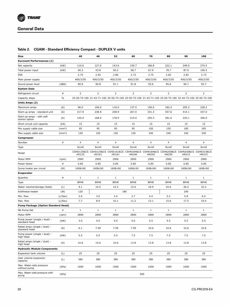
Table 2. CGAM - Standard Efficiency Compact - DUPLEX V units
Size 40 46 52 60 70 80 90 100
Eurovent Performances (1)
Net capacity (kW) 110.6 127.6 143.6 159.7 186.8 222.1 249.0 274.5
Total power input (kW) 40.3 43.8 50.2 58.7 67.9 78.7 87.9 100.5
EER 2.75 2.92 2.86 2.72 2.75 2.82 2.83 2.73
Main power supply 400/3/50 400/3/50 400/3/50 400/3/50 400/3/50 400/3/50 400/3/50 400/3/50
Sound power level (dBA) 90.9 90.8 91.1 91.8 93.6 95.6 94.7 93.7
System Data
Refrigerant circuit # 2 2 2 2 2 2 2 2
Capacity steps % 25-50-75-100 21-43-71-100 25-50-75-100 25-50-75-100 21-43-71-100 25-50-75-100 22-44-72-100 25-50-75-100
Units Amps (2)
Maximum amps (A) 96.0 106.0 116.0 137.5 156.0 182.4 205.3 228.2
Start-up amps - standard unit (A) 217.9 238.9 248.9 267.0 331.3 357.6 414.1 437.0
Start-up amps - with soft starter option
(A) 145.9 168.9 178.9 214.0 255.3 281.6 333.1 356.0
Short circuit unit capacity (kA) 15 15 15 15 15 15 15 15
Min supply cable size (mm²) 95 95 95 95 150 150 185 185
Max supply cable size (mm²) 150 150 150 150 240 240 240 240
Compressor
Number # 4 4 4 4 4 4 4 4
Type Scroll Scroll Scroll Scroll Scroll Scroll Scroll Scroll
ModelCSHD125&CS
HD125CSHD125&CS
HD161CSHD161&CS
HD161CSHN184&CS
HN184CSHN184&CS
HN250CSHN250&CS
HN250CSHN250&CS
HN315CSHN315&CS
HN315
Motor RPM (rpm) 2900 2900 2900 2900 2900 2900 2900 2900
Power factor # 0.85 0.85 0.85 0.85 0.85 0.85 0.85 0.85
Sump heater per circuit (W) 160&160 160&160 160&160 160&160 160&160 160&160 160&160 160&160
Evaporator
Quantity # 1 1 1 1 1 1 1 1
Type BPHE BPHE BPHE BPHE BPHE BPHE BPHE BPHE
Water volume/storage (total) (L) 9.1 10.5 14.3 15.6 18.9 24.0 26.5 32.4
Antifreeze heater (W) 120 180 240
Min. flow (L/Sec) 2.6 3.0 3.4 3.7 4.4 5.2 5.8 6.5
Max. flow (L/Sec) 7.7 8.9 10.1 11.2 13.1 15.6 17.5 19.4
Pump Package (Option Standard Head)
Nb Pump Set # 1 1 1 1 1 1 1 1
Motor RPM (rpm) 2890 2890 2890 2890 2890 2890 2890 2890
Pump power (single / dual) - standard head
(kW) 3.0 4.0 4.0 4.0 5.5 5.5 5.5 5.5
Rated amps (single / dual) - standard head
(A) 6.1 7.59 7.59 7.59 10.6 10.6 10.6 10.6
Pump power (single / dual) - high head
(kW) 5.5 5.5 5.5 7.5 7.5 7.5 7.5 7.5
Rated amps (single / dual) - high head
(A) 10.6 10.6 10.6 13.8 13.8 13.8 13.8 13.8
Hydraulic Module Components
Expansion tank volume (L) 25 25 25 25 25 25 25 25
User volume expansion capacity
(L) 380 380 380 380 380 380 380 380
Max. Water-side pressure without pump
(kPa) 1000 1000 1000 1000 1000 1000 1000 1000
Max. Water-side pressure with pump
(kPa) 400
CG-PRC019-E4 21
General Data
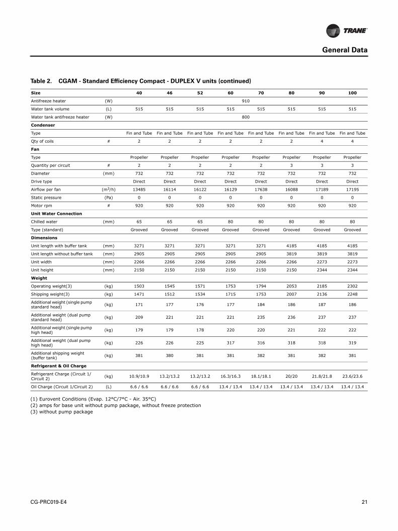
(1) Eurovent Conditions (Evap. 12°C/7°C - Air. 35°C)
(2) amps for base unit without pump package, without freeze protection
(3) without pump package
Antifreeze heater (W) 910
Water tank volume (L) 515 515 515 515 515 515 515 515
Water tank antifreeze heater (W) 800
Condenser
Type Fin and Tube Fin and Tube Fin and Tube Fin and Tube Fin and Tube Fin and Tube Fin and Tube Fin and Tube
Qty of coils # 2 2 2 2 2 2 4 4
Fan
Type Propeller Propeller Propeller Propeller Propeller Propeller Propeller Propeller
Quantity per circuit # 2 2 2 2 2 3 3 3
Diameter (mm) 732 732 732 732 732 732 732 732
Drive type Direct Direct Direct Direct Direct Direct Direct Direct
Airflow per fan (m3/h) 13485 16114 16122 16129 17638 16088 17189 17195
Static pressure (Pa) 0 0 0 0 0 0 0 0
Motor rpm # 920 920 920 920 920 920 920 920
Unit Water Connection
Chilled water (mm) 65 65 65 80 80 80 80 80
Type (standard) Grooved Grooved Grooved Grooved Grooved Grooved Grooved Grooved
Dimensions
Unit length with buffer tank (mm) 3271 3271 3271 3271 3271 4185 4185 4185
Unit length without buffer tank (mm) 2905 2905 2905 2905 2905 3819 3819 3819
Unit width (mm) 2266 2266 2266 2266 2266 2266 2273 2273
Unit height (mm) 2150 2150 2150 2150 2150 2150 2344 2344
Weight
Operating weight(3) (kg) 1503 1545 1571 1753 1794 2053 2185 2302
Shipping weight(3) (kg) 1471 1512 1534 1715 1753 2007 2136 2248
Additional weight (single pump standard head)
(kg) 171 177 176 177 184 186 187 186
Additional weight (dual pump standard head)
(kg) 209 221 221 221 235 236 237 237
Additional weight (single pump high head)
(kg) 179 179 178 220 220 221 222 222
Additional weight (dual pump high head)
(kg) 226 226 225 317 316 318 318 319
Additional shipping weight (buffer tank)
(kg) 381 380 381 381 382 381 382 381
Refrigerant & Oil Charge
Refrigerant Charge (Circuit 1/Circuit 2)
(kg) 10.9/10.9 13.2/13.2 13.2/13.2 16.3/16.3 18.1/18.1 20/20 21.8/21.8 23.6/23.6
Oil Charge (Circuit 1/Circuit 2) (L) 6.6 / 6.6 6.6 / 6.6 6.6 / 6.6 13.4 / 13.4 13.4 / 13.4 13.4 / 13.4 13.4 / 13.4 13.4 / 13.4
Table 2. CGAM - Standard Efficiency Compact - DUPLEX V units (continued)
Size 40 46 52 60 70 80 90 100

22 CG-PRC019-E4
General Data
Table 3. CGAM - Standard Efficiency Compact - DUPLEX W units
Size 110 120 140 150 160 170
Eurovent Performances (1)
Net capacity (kW) 296.7 327.2 380.9 407.4 434.2 460.5
Total power input (kW) 106.8 110.6 130.7 143.5 151.5 156.2
EER 2.78 2.96 2.91 2.84 2.86 2.95
Main power supply 400/3/50 400/3/50 400/3/50 400/3/50 400/3/50 400/3/50
Sound power level (dBA) 95.2 93.4 94.7 93.0 94.1 94.6
System Data
Refrigerant circuit # 2 2 2 2 2 2
Capacity steps % 23-45-73-100 25-50-75-10014-29-46-64-82-
10017-33-50-67-83-
10016-31-47-63-81-
10015-29-47-65-82-
100
Units Amps (2)
Maximum amps (A) 241.6 255.0 314.5 330.6 350.8 364.2
Start-up amps - standard unit (A) 503.7 517.1 523.3 539.4 612.9 626.3
Start-up amps - with soft starter option
(A) 386.7 400.1 442.3 458.4 495.9 509.3
Short circuit unit capacity (kA) 15 15 15 15 15 15
Min supply cable size (mm²) 150 185 240 240 240 240
Max supply cable size (mm²) 240 240 240 240 240 240
Compressor
Number # 4 4 6 6 6 6
Type Scroll Scroll Scroll Scroll Scroll Scroll
ModelCSHN315&CSHN3
74CSHN374&CSHN3
74CSHN250&CSHN315&CSHN315
CSHN315&CSHN315&CSHN315
CSHN315&CSHN315&CSHN374
CSHN315&CSHN374&CSHN374
Motor RPM (rpm) 2900 2900 2900 2900 2900 2900
Power factor # 0.85 0.85 0.85 0.85 0.85 0.85
Sump heater per circuit (W) 160&160 160&160 160&160&160 160&160&160 160&160&160 160&160&160
Evaporator
Quantity # 1 1 1 1 1 1
Type BPHE BPHE BPHE BPHE BPHE BPHE
Water volume/storage (total) (L) 32.4 34.1 40.8 46.7 46.7 46.7
Antifreeze heater (W) 240 300
Min. flow (L/Sec) 7.0 7.7 9.0 9.6 10.2 10.8
Max. flow (L/Sec) 21.0 23.2 27.1 28.8 30.7 32.5
Pump Package (Option Standard Head)
Nb Pump Set # 1 1 1 1 1 1
Motor RPM (rpm) 2900 2900 2900 2900 2900 2900
Pump power (single / dual) - standard head
(kW) 7.5 7.5 11.0 11.0 11.0 11.0
Rated amps (single / dual) - standard head
(A) 13.8 13.8 19.6 19.6 19.6 19.6
Pump power (single / dual) - high head
(kW) 7.5 11.0 11.0 11.0 15.0 15.0
Rated amps (single / dual) - high head
(A) 13.8 19.6 19.6 19.6 26.5 26.5
Hydraulic Module Components
Expansion tank volume (L) 60 60 60 60 60 60
User volume expansion capacity
(L) 1750 1750 1750 1750 1750 1750
Max. Water-side pressure without pump
(kPa) 1000 1000 1000 1000 1000 1000

CG-PRC019-E4 23
General Data
(1) Eurovent Conditions (Evap. 12°C/7°C - Air. 35°C)
(2) amps for base unit without pump package, without freeze protection
(3) without pump package
Max. Water-side pressure with pump
(kPa) 500 500 500 500 500 500
Antifreeze heater (W) 300
Pump package anti freeze heater
(W) 1150
Water tank antifreeze heater (W) 800 1200
Water tank volume (L) 592 592 762 762 762 762
Condenser
Type Fin and Tube Fin and Tube Fin and Tube Fin and Tube Fin and Tube Fin and Tube
Qty of coils # 4 4 4 4 4 4
Fan
Type Propeller Propeller Propeller Propeller Propeller Propeller
Quantity per circuit # 3 3 4 3 4 4
Diameter (mm) 732 732 732 732 732 732
Drive type Direct Direct Direct Direct Direct Direct
Airflow per fan (m3/h) 18757 17770 17092 18618 17097 18325
Static pressure (Pa) 0 0 0 0 0 0
Motor rpm # 920 920 920 920 920 920
Unit Water Connection
Chilled water (mm) 100 100 100 100 100 100
Type (standard) Grooved Grooved Grooved Grooved Grooved Grooved
Dimensions
Unit length with buffer tank (mm) 3647 3647 4230 4230 4230 5145
Unit length without buffer tank (mm) 3647 3647 4230 4230 4230 5145
Unit width (mm) 2273 2273 2273 2273 2273 2273
Unit height (mm) 2344 2344 2344 2344 2344 2344
Weight
Operating weight(3) (kg) 2494 2615 3055 3082 3172 3426
Shipping weight(3) (kg) 2440 2560 2993 3014 3104 3359
Additional weight (single pump standard head)
(kg) 314 314 354 355 355 376
Additional weight (dual pump standard head)
(kg) 405 405 487 488 488 509
Additional weight (single pump high head)
(kg) 310 356 355 355 368 389
Additional weight (dual pump high head)
(kg) 407 489 488 489 515 536
Additional shipping weight (buffer tank)
(kg) 203 203 251 251 252 252
Refrigerant & Oil Charge
Refrigerant Charge (Circuit 1/Circuit 2)
(kg) 27.2/27.2 33.6/33.6 41.7/41.7 40.8/40.8 42.6/42.6 51.7/51.7
Oil Charge (Circuit 1/Circuit 2) (L) 13.9 / 13.9 14.4 / 14.4 20.1 / 20.1 20.1 / 20.1 20.6 / 20.6 21.1 / 21.1
Table 3. CGAM - Standard Efficiency Compact - DUPLEX W units (continued)
Size 110 120 140 150 160 170

24 CG-PRC019-E4
General Data
Table 4. CGAM - Standard Efficiency Super Quiet - SIMPLEX units
Size 20 23 26 30 35 39 45 50
Eurovent Performances (1)
Net capacity (kW) 54.2 62.4 68.7 78.2 90.1 108.3 120.5 131.8
Total power input (kW) 20.0 21.7 25.0 29.8 34.3 39.5 44.2 50.8
EER 2.70 2.87 2.74 2.62 2.62 2.74 2.72 2.60
Main power supply 400/3/50 400/3/50 400/3/50 400/3/50 400/3/50 400/3/50 400/3/50 400/3/50
Sound power level (dBA) 82.5 82.4 82.4 83.0 84.7 86.7 86.0 85.2
System Data
Refrigerant circuit # 1 1 1 1 1 1 1 1
Capacity steps % 50-100 43-100 50-100 50-100 43-100 50-100 22-44-72-100 50-100
Units Amps (2)
Maximum amps (A) 50.3 55.3 60.3 71.1 80.3 93.9 105.3 116.8
Start-up amps - standard unit (A) 172.2 188.2 193.2 200.6 255.6 269.1 314.1 325.6
Start-up amps - with soft starter option
(A) 100.2 118.2 123.2 147.6 179.6 193.1 233.1 244.6
Short circuit unit capacity (kA) 15 15 15 15 15 15 15 15
Min supply cable size (mm2) 50 50 50 50 95 95 95 95
Max supply cable size (mm2) 95 95 95 95 150 150 150 150
Compressor
Number # 2 2 2 2 2 2 2 2
Type Scroll Scroll Scroll Scroll Scroll Scroll Scroll Scroll
ModelCSHD125&CS
HD125CSHD125&CS
HD161CSHD161&CS
HD161CSHN184&CS
HN184CSHN184&CS
HN250CSHN250&CS
HN250CSHN250&CS
HN315CSHN315&CS
HN315
Motor RPM (rpm) 2900 2900 2900 2900 2900 2900 2900 2900
Power factor # 0.85 0.85 0.85 0.85 0.85 0.85 0.85 0.85
Sump heater per circuit (W) 90&90 90&90 90&90 160&160 160&160 160&160 160&160 160&160
Evaporator
Quantity # 1 1 1 1 1 1 1 1
Type BPHE BPHE BPHE BPHE BPHE BPHE BPHE BPHE
Water volume/storage (total) (L) 4.0 4.0 4.0 6.7 6.7 10.6 10.6 13.3
Antifreeze heater (W) 120 180
Min. flow (L/Sec) 1.3 1.5 1.6 1.8 2.1 2.5 2.8 3.1
Max. flow (L/Sec) 3.8 4.4 4.8 5.5 6.3 7.6 8.5 9.3
Pump Package (Option Standard Head)
Nb Pump Set # 1 1 1 1 1 1 1 1
Motor RPM (rpm) 2860 2860 2860 2860 2860 2890 2890 2890
Pump power (single / dual) - standard head
(kW) 1.5 1.5 1.5 1.5 1.5 3.0 3.0 3.0
Rated amps (single / dual) - standard head
(A) 3.25 3.25 3.25 3.25 3.25 6.1 6.1 6.1
Pump power (single / dual) - high head
(kW) 4.0 4.0 4.0 4.0 5.5 5.5 5.5 5.5
Rated amps (single / dual) - high head
(A) 7.59 7.59 7.59 7.59 10.6 10.6 10.6 10.6
Hydraulic Module Components
Expansion tank volume (L) 25 25 25 25 25 25 25 25
User volume expansion capacity
(L) 380 380 380 380 380 380 380 380
Max. Water-side pressure without pump
(kPa) 1000 1000 1000 1000 1000 1000 1000 1000
Max. Water-side pressure with pump
(kPa) 400
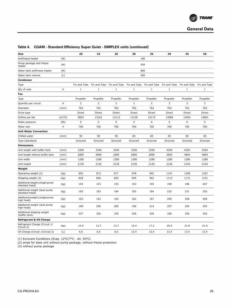
CG-PRC019-E4 25
General Data
(1) Eurovent Conditions (Evap. 12°C/7°C - Air. 35°C)
(2) amps for base unit without pump package, without freeze protection
(3) without pump package
Antifreeze heater (W) 180
Pump package anti freeze heater
(W) 530
Water tank antifreeze heater (W) 860
Water tank volume (L) 500
Condenser
Type Fin and Tube Fin and Tube Fin and Tube Fin and Tube Fin and Tube Fin and Tube Fin and Tube Fin and Tube
Qty of coils # 1 1 1 1 1 1 1 1
Fan
Type Propeller Propeller Propeller Propeller Propeller Propeller Propeller Propeller
Quantity per circuit # 2 2 2 2 2 3 3 3
Diameter (mm) 762 762 762 762 762 762 762 762
Drive type Direct Direct Direct Direct Direct Direct Direct Direct
Airflow per fan (m3/h) 9824 13101 13113 13130 15172 13068 14591 14601
Static pressure (Pa) 0 0 0 0 0 0 0 0
Motor rpm # 700 700 700 700 700 700 700 700
Unit Water Connection
Chilled water (mm) 50 50 50 65 65 65 65 65
Type (standard) Grooved Grooved Grooved Grooved Grooved Grooved Grooved Grooved
Dimensions
Unit length with buffer tank (mm) 3340 3340 3340 3340 3340 4254 4254 4254
Unit length without buffer tank (mm) 2890 2890 2890 2890 2890 3804 3804 3804
Unit width (mm) 1280 1280 1280 1280 1280 1280 1280 1280
Unit height (mm) 2145 2145 2145 2145 2145 2145 2145 2145
Weight
Operating weight (3) (kg) 855 873 877 978 992 1147 1208 1267
Shipping weight (3) (kg) 828 846 850 949 962 1113 1175 1231
Additional weight (single pump standard head)
(kg) 154 153 153 153 155 199 198 207
Additional weight (dual pump standard head)
(kg) 183 183 184 183 184 232 231 250
Additional weight (single pump high head)
(kg) 163 163 162 162 167 209 208 208
Additional weight (dual pump high head)
(kg) 199 200 200 199 214 257 255 255
Additional shipping weight (buffer tank)
(kg) 327 326 325 326 326 326 326 326
Refrigerant & Oil Charge
Refrigerant Charge (Circuit 1/Circuit 2)
(kg) 10.9 12.7 12.7 15.4 17.2 20.0 21.8 21.8
Oil Charge (Circuit 1/Circuit 2) (L) 6.6 6.6 6.6 13.4 13.4 13.4 13.4 13.4
Table 4. CGAM - Standard Efficiency Super Quiet - SIMPLEX units (continued)
Size 20 23 26 30 35 39 45 50

26 CG-PRC019-E4
General Data
Table 5. CGAM - Standard Efficiency Super Quiet - DUPLEX V units
Size 40 46 52 60 70 80 90 100
Eurovent Performances (1)
Net capacity (kW) 107.9 125.9 141.2 156.5 184.0 218.3 245.6 270.0
Total power input (kW) 39.6 43.1 49.8 58.9 68.3 78.5 87.6 100.6
EER 2.73 2.92 2.83 2.66 2.70 2.78 2.80 2.68
Main power supply 400/3/50 400/3/50 400/3/50 400/3/50 400/3/50 400/3/50 400/3/50 400/3/50
Sound power level (dBA) 85.4 85.3 85.5 86.0 87.6 89.5 88.8 88.0
System Data
Refrigerant circuit # 2 2 2 2 2 2 2 2
Capacity steps % 25-50-75-100 21-43-71-100 25-50-75-100 25-50-75-100 21-43-71-100 25-50-75-100 22-44-72-100 25-50-75-100
Units Amps (2)
Maximum amps (A) 99.6 109.6 119.6 141.1 159.6 186.8 209.7 232.6
Start-up amps - standard unit (A) 221.5 242.5 252.5 270.6 334.9 362.0 418.5 441.4
Start-up amps - with soft starter option
(A) 149.5 172.5 182.5 217.6 258.9 286.0 337.5 360.4
Short circuit unit capacity (kA) 15 15 15 15 15 15 15 15
Min supply cable size (mm²) 95 95 95 95 150 150 185 185
Max supply cable size (mm²) 150 150 150 150 240 240 240 240
Compressor
Number # 4 4 4 4 4 4 4 4
Type Scroll Scroll Scroll Scroll Scroll Scroll Scroll Scroll
ModelCSHD125&CS
HD125CSHD125&CS
HD161CSHD161&CS
HD161CSHN184&CS
HN184CSHN184&CS
HN250CSHN250&CS
HN250CSHN250&CS
HN315CSHN315&CS
HN315
Motor RPM (rpm) 2900 2900 2900 2900 2900 2900 2900 2900
Power factor # 0.85 0.85 0.85 0.85 0.85 0.85 0.85 0.85
Sump heater per circuit (W) 160&160 160&160 160&160 160&160 160&160 160&160 160&160 160&160
Evaporator
Quantity # 1 1 1 1 1 1 1 1
Type BPHE BPHE BPHE BPHE BPHE BPHE BPHE BPHE
Water volume/storage (total) (L) 9.1 10.5 14.3 15.6 18.9 24.0 26.5 32.4
Antifreeze heater (W) 120 180 240
Min. flow (L/Sec) 2.5 2.9 3.3 3.7 4.3 5.1 5.8 6.3
Max. flow (L/Sec) 7.5 8.8 9.9 11.0 12.9 15.4 17.3 19.0
Pump Package (Option Standard Head)
Nb Pump Set # 1 1 1 1 1 1 1 1
Motor RPM (rpm) 2890 2890 2890 2890 2890 2890 2890 2890
Pump power (single / dual) - standard head
(kW) 3.0 4.0 4.0 4.0 5.5 5.5 5.5 5.5
Rated amps (single / dual) - standard head
(A) 6.1 7.59 7.59 7.59 10.6 10.6 10.6 10.6
Pump power (single / dual) - high head
(kW) 5.5 5.5 5.5 7.5 7.5 7.5 7.5 7.5
Rated amps (single / dual) - high head
(A) 10.6 10.6 10.6 13.8 13.8 13.8 13.8 13.8
Hydraulic Module Components
Expansion tank volume (L) 25 25 25 25 25 25 25 25
User volume expansion capacity
(L) 380 380 380 380 380 380 380 380
Max. Water-side pressure without pump
(kPa) 1000 1000 1000 1000 1000 1000 1000 1000
Max. Water-side pressure with pump
(kPa) 400
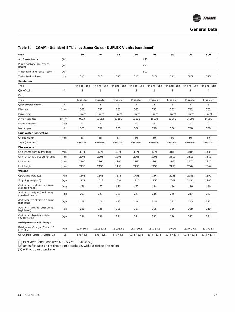
CG-PRC019-E4 27
General Data
(1) Eurovent Conditions (Evap. 12°C/7°C - Air. 35°C)
(2) amps for base unit without pump package, without freeze protection
(3) without pump package
Antifreeze heater (W) 120
Pump package anti freeze heater
(W) 910
Water tank antifreeze heater (W) 800
Water tank volume (L) 515 515 515 515 515 515 515 515
Condenser
Type Fin and Tube Fin and Tube Fin and Tube Fin and Tube Fin and Tube Fin and Tube Fin and Tube Fin and Tube
Qty of coils # 2 2 2 2 2 2 4 4
Fan
Type Propeller Propeller Propeller Propeller Propeller Propeller Propeller Propeller
Quantity per circuit # 2 2 2 2 2 3 3 3
Diameter (mm) 762 762 762 762 762 762 762 762
Drive type Direct Direct Direct Direct Direct Direct Direct Direct
Airflow per fan (m3/h) 9824 13102 13115 13130 15173 13069 14592 14603
Static pressure (Pa) 0 0 0 0 0 0 0 0
Motor rpm # 700 700 700 700 700 700 700 700
Unit Water Connection
Chilled water (mm) 65 65 65 80 80 80 80 80
Type (standard) Grooved Grooved Grooved Grooved Grooved Grooved Grooved Grooved
Dimensions
Unit length with buffer tank (mm) 3271 3271 3271 3271 3271 4185 4185 4185
Unit length without buffer tank (mm) 2905 2905 2905 2905 2905 3819 3819 3819
Unit width (mm) 2266 2266 2266 2266 2266 2266 2273 2273
Unit height (mm) 2150 2150 2150 2150 2150 2150 2344 2344
Weight
Operating weight(3) (kg) 1503 1545 1571 1753 1794 2053 2185 2302
Shipping weight(3) (kg) 1471 1512 1534 1715 1753 2007 2136 2248
Additional weight (single pump standard head)
(kg) 171 177 176 177 184 186 186 186
Additional weight (dual pump standard head)
(kg) 209 221 221 221 235 236 237 237
Additional weight (single pump high head)
(kg) 179 179 178 220 220 222 223 222
Additional weight (dual pump high head)
(kg) 226 226 225 317 316 319 318 319
Additional shipping weight (buffer tank)
(kg) 381 380 381 381 382 380 382 381
Refrigerant & Oil Charge
Refrigerant Charge (Circuit 1/Circuit 2)
(kg) 10.9/10.9 13.2/13.2 13.2/13.2 16.3/16.3 18.1/18.1 20/20 20.9/20.9 22.7/22.7
Oil Charge (Circuit 1/Circuit 2) (L) 6.6 / 6.6 6.6 / 6.6 6.6 / 6.6 13.4 / 13.4 13.4 / 13.4 13.4 / 13.4 13.4 / 13.4 13.4 / 13.4
Table 5. CGAM - Standard Efficiency Super Quiet - DUPLEX V units (continued)
Size 40 46 52 60 70 80 90 100

28 CG-PRC019-E4
General Data
Table 6. CGAM - Standard Efficiency Super Quiet - DUPLEX W units
Size 110 120 140 150 160 170
Eurovent Performances (1)
Net capacity (kW) 291.7 321.6 374.3 399.8 424.5 453.8
Total power input (kW) 107.5 112.2 132.3 145.8 154.5 158.1
EER 2.71 2.87 2.83 2.74 2.75 2.87
Main power supply 400/3/50 400/3/50 400/3/50 400/3/50 400/3/50 400/3/50
Sound power level (dBA) 89.7 88.1 88.7 87.2 88.5 89.1
System Data
Refrigerant circuit # 2 2 2 2 2 2
Capacity steps % 23-45-73-100 25-50-75-10014-29-46-64-82-
10017-33-50-67-83-
10016-31-47-63-81-
10015-29-47-65-82-
100
Units Amps (2)
Maximum amps (A) 246.0 259.4 320.7 335.0 357.0 370.4
Start-up amps - standard unit (A) 508.1 521.5 529.5 543.8 619.1 632.5
Start-up amps - with soft starter option
(A) 391.1 404.5 448.5 462.8 502.1 515.5
Short circuit unit capacity (kA) 15 15 15 15 15 15
Min supply cable size (mm²) 150 185 240 240 240 240
Max supply cable size (mm²) 240 240 240 240 240 240
Compressor
Number # 4 4 6 6 6 6
Type Scroll Scroll Scroll Scroll Scroll Scroll
ModelCSHN315&CSHN3
74CSHN374&CSHN3
74CSHN250&CSHN315&CSHN315
CSHN315&CSHN315&CSHN315
CSHN315&CSHN315&CSHN374
CSHN315&CSHN374&CSHN374
Motor RPM (rpm) 2900 2900 2900 2900 2900 2900
Power factor # 0.85 0.85 0.85 0.85 0.85 0.85
Sump heater per circuit (W) 160&160 160&160 160&160&160 160&160&160 160&160&160 160&160&160
Evaporator
Quantity # 1 1 1 1 1 1
Type BPHE BPHE BPHE BPHE BPHE BPHE
Water volume/storage (total) (L) 32.4 34.1 40.8 46.7 46.7 46.7
Antifreeze heater (W) 400 500 500 500 500 500
Min. flow (L/Sec) 6.9 7.6 8.9 9.4 10.0 10.7
Max. flow (L/Sec) 20.6 22.8 26.6 28.2 30.0 32.0
Pump Package (Option Standard Head)
Nb Pump Set # 1 1 1 1 1 1
Motor RPM (rpm) 2900 2900 2900 2900 2900 2900
Pump power (single / dual) - standard head
(kW) 7.5 7.5 11.0 11.0 11.0 11.0
Rated amps (single / dual) - standard head
(A) 13.8 13.8 19.6 19.6 19.6 19.6
Pump power (single / dual) - high head
(kW) 7.5 11.0 11.0 11.0 15.0 15.0
Rated amps (single / dual) - high head
(A) 13.8 19.6 19.6 19.6 26.5 26.5
Hydraulic Module Components
(mm) 100 100 100 100 100 100
Expansion tank volume (L) 60 60 60 60 60 60
User volume expansion capacity
(L) 1750 1750 1750 1750 1750 1750
Max. Water-side pressure without pump
(kPa) 1000 1000 1000 1000 1000 1000
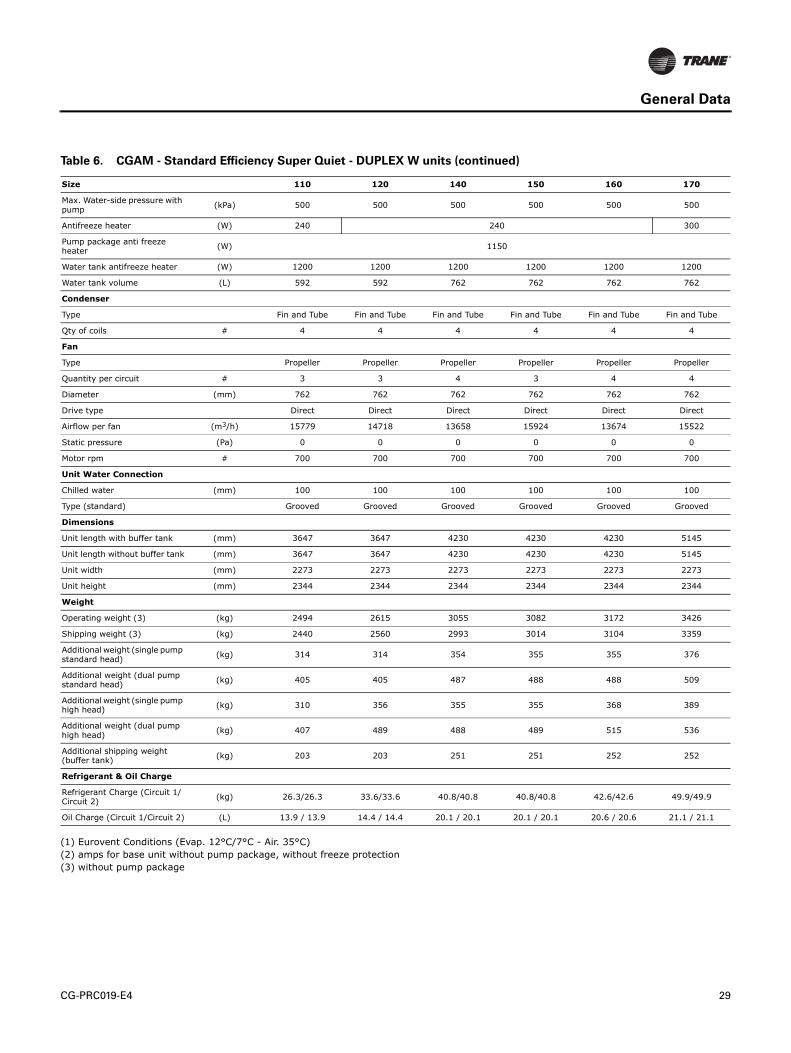
CG-PRC019-E4 29
General Data
(1) Eurovent Conditions (Evap. 12°C/7°C - Air. 35°C)
(2) amps for base unit without pump package, without freeze protection
(3) without pump package
Max. Water-side pressure with pump
(kPa) 500 500 500 500 500 500
Antifreeze heater (W) 240 240 300
Pump package anti freeze heater
(W) 1150
Water tank antifreeze heater (W) 1200 1200 1200 1200 1200 1200
Water tank volume (L) 592 592 762 762 762 762
Condenser
Type Fin and Tube Fin and Tube Fin and Tube Fin and Tube Fin and Tube Fin and Tube
Qty of coils # 4 4 4 4 4 4
Fan
Type Propeller Propeller Propeller Propeller Propeller Propeller
Quantity per circuit # 3 3 4 3 4 4
Diameter (mm) 762 762 762 762 762 762
Drive type Direct Direct Direct Direct Direct Direct
Airflow per fan (m3/h) 15779 14718 13658 15924 13674 15522
Static pressure (Pa) 0 0 0 0 0 0
Motor rpm # 700 700 700 700 700 700
Unit Water Connection
Chilled water (mm) 100 100 100 100 100 100
Type (standard) Grooved Grooved Grooved Grooved Grooved Grooved
Dimensions
Unit length with buffer tank (mm) 3647 3647 4230 4230 4230 5145
Unit length without buffer tank (mm) 3647 3647 4230 4230 4230 5145
Unit width (mm) 2273 2273 2273 2273 2273 2273
Unit height (mm) 2344 2344 2344 2344 2344 2344
Weight
Operating weight (3) (kg) 2494 2615 3055 3082 3172 3426
Shipping weight (3) (kg) 2440 2560 2993 3014 3104 3359
Additional weight (single pump standard head)
(kg) 314 314 354 355 355 376
Additional weight (dual pump standard head)
(kg) 405 405 487 488 488 509
Additional weight (single pump high head)
(kg) 310 356 355 355 368 389
Additional weight (dual pump high head)
(kg) 407 489 488 489 515 536
Additional shipping weight (buffer tank)
(kg) 203 203 251 251 252 252
Refrigerant & Oil Charge
Refrigerant Charge (Circuit 1/Circuit 2)
(kg) 26.3/26.3 33.6/33.6 40.8/40.8 40.8/40.8 42.6/42.6 49.9/49.9
Oil Charge (Circuit 1/Circuit 2) (L) 13.9 / 13.9 14.4 / 14.4 20.1 / 20.1 20.1 / 20.1 20.6 / 20.6 21.1 / 21.1
Table 6. CGAM - Standard Efficiency Super Quiet - DUPLEX W units (continued)
Size 110 120 140 150 160 170
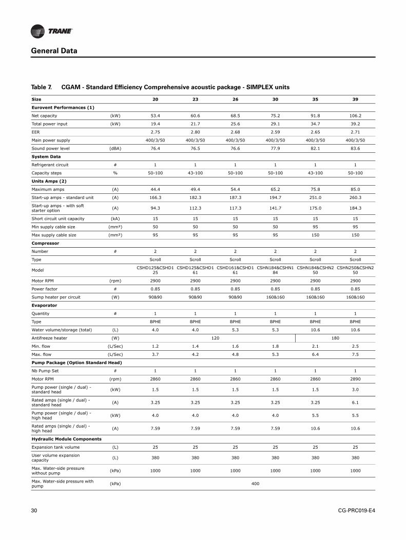
30 CG-PRC019-E4
General Data
Table 7. CGAM - Standard Efficiency Comprehensive acoustic package - SIMPLEX units
Size 20 23 26 30 35 39
Eurovent Performances (1)
Net capacity (kW) 53.4 60.6 68.5 75.2 91.8 106.2
Total power input (kW) 19.4 21.7 25.6 29.1 34.7 39.2
EER 2.75 2.80 2.68 2.59 2.65 2.71
Main power supply 400/3/50 400/3/50 400/3/50 400/3/50 400/3/50 400/3/50
Sound power level (dBA) 76.4 76.5 76.6 77.9 82.1 83.6
System Data
Refrigerant circuit # 1 1 1 1 1 1
Capacity steps % 50-100 43-100 50-100 50-100 43-100 50-100
Units Amps (2)
Maximum amps (A) 44.4 49.4 54.4 65.2 75.8 85.0
Start-up amps - standard unit (A) 166.3 182.3 187.3 194.7 251.0 260.3
Start-up amps - with soft starter option
(A) 94.3 112.3 117.3 141.7 175.0 184.3
Short circuit unit capacity (kA) 15 15 15 15 15 15
Min supply cable size (mm²) 50 50 50 50 95 95
Max supply cable size (mm²) 95 95 95 95 150 150
Compressor
Number # 2 2 2 2 2 2
Type Scroll Scroll Scroll Scroll Scroll Scroll
ModelCSHD125&CSHD1
25CSHD125&CSHD1
61CSHD161&CSHD1
61CSHN184&CSHN1
84CSHN184&CSHN2
50CSHN250&CSHN2
50
Motor RPM (rpm) 2900 2900 2900 2900 2900 2900
Power factor # 0.85 0.85 0.85 0.85 0.85 0.85
Sump heater per circuit (W) 90&90 90&90 90&90 160&160 160&160 160&160
Evaporator
Quantity # 1 1 1 1 1 1
Type BPHE BPHE BPHE BPHE BPHE BPHE
Water volume/storage (total) (L) 4.0 4.0 5.3 5.3 10.6 10.6
Antifreeze heater (W) 120 180
Min. flow (L/Sec) 1.2 1.4 1.6 1.8 2.1 2.5
Max. flow (L/Sec) 3.7 4.2 4.8 5.3 6.4 7.5
Pump Package (Option Standard Head)
Nb Pump Set # 1 1 1 1 1 1
Motor RPM (rpm) 2860 2860 2860 2860 2860 2890
Pump power (single / dual) - standard head
(kW) 1.5 1.5 1.5 1.5 1.5 3.0
Rated amps (single / dual) - standard head
(A) 3.25 3.25 3.25 3.25 3.25 6.1
Pump power (single / dual) - high head
(kW) 4.0 4.0 4.0 4.0 5.5 5.5
Rated amps (single / dual) - high head
(A) 7.59 7.59 7.59 7.59 10.6 10.6
Hydraulic Module Components
Expansion tank volume (L) 25 25 25 25 25 25
User volume expansion capacity
(L) 380 380 380 380 380 380
Max. Water-side pressure without pump
(kPa) 1000 1000 1000 1000 1000 1000
Max. Water-side pressure with pump
(kPa) 400

CG-PRC019-E4 31
General Data
(1) Eurovent Conditions (Evap. 12°C/7°C - Air. 35°C)
(2) amps for base unit without pump package, without freeze protection
(3) without pump package
Antifreeze heater (W) 180
Pump package anti freeze heater
(W) 530
Water tank antifreeze heater (W) 860
Water tank volume (L) 500
Condenser
Type Fin and Tube Fin and Tube Fin and Tube Fin and Tube Fin and Tube Fin and Tube
Qty of coils # 1 1 1 1 1 1
Fan
Type Propeller Propeller Propeller Propeller Propeller Propeller
Quantity per circuit # 2 2 2 2 3 3
Diameter (mm) 757 757 757 757 757 757
Drive type Direct Direct Direct Direct Direct Direct
Airflow per fan (m3/h) 8559 9520 9525 10085 8929 9917
Static pressure (Pa) 0 0 0 0 0 0
Motor rpm # 700 700 700 700 700 700
Unit Water Connection
Chilled water (mm) 50 50 50 65 65 65
Type (standard) Grooved Grooved Grooved Grooved Grooved Grooved
Dimensions
Unit length with buffer tank (mm) 3340 3340 3340 3340 4254 4254
Unit length without buffer tank (mm) 2890 2890 2890 2890 3804 3804
Unit width (mm) 1280 1280 1280 1280 1280 1280
Unit height (mm) 2145 2145 2145 2145 2145 2145
Weight
Operating weight(3) (kg) 889 907 916 1031 1179 1206
Shipping weight(3) (kg) 862 880 888 1003 1146 1173
Additional weight (single pump standard head)
(kg) 154 154 154 154 195 198
Additional weight (dual pump standard head)
(kg) 184 183 184 183 225 231
Additional weight (single pump high head)
(kg) 163 162 163 163 207 208
Additional weight (dual pump high head)
(kg) 200 199 200 200 255 255
Additional shipping weight (buffer tank)
(kg) 326 326 326 326 326 326
Refrigerant & Oil Charge
Refrigerant Charge (Circuit 1/Circuit 2)
(kg) 10.9 12.7 12.7 16.3 17.2 20.0
Oil Charge (Circuit 1/Circuit 2) (L) 6.6 6.6 6.6 13.4 13.4 13.4
Table 7. CGAM - Standard Efficiency Comprehensive acoustic package - SIMPLEX units (continued)
Size 20 23 26 30 35 39
32 CG-PRC019-E4
General Data
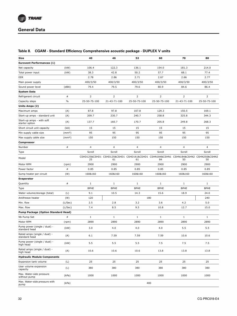
Table 8. CGAM - Standard Efficiency Comprehensive acoustic package - DUPLEX V units
Size 40 46 52 60 70 80
Eurovent Performances (1)
Net capacity (kW) 106.4 122.3 136.1 154.0 181.3 214.0
Total power input (kW) 38.3 42.8 50.2 57.7 68.1 77.4
EER 2.78 2.86 2.71 2.67 2.66 2.77
Main power supply 400/3/50 400/3/50 400/3/50 400/3/50 400/3/50 400/3/50
Sound power level (dBA) 79.4 79.5 79.6 80.9 84.6 86.4
System Data
Refrigerant circuit # 2 2 2 2 2 2
Capacity steps % 25-50-75-100 21-43-71-100 25-50-75-100 25-50-75-100 21-43-71-100 25-50-75-100
Units Amps (2)
Maximum amps (A) 87.8 97.8 107.8 129.3 150.5 169.1
Start-up amps - standard unit (A) 209.7 230.7 240.7 258.8 325.8 344.3
Start-up amps - with soft starter option
(A) 137.7 160.7 170.7 205.8 249.8 268.3
Short circuit unit capacity (kA) 15 15 15 15 15 15
Min supply cable size (mm²) 95 95 95 95 95 95
Max supply cable size (mm²) 150 150 150 150 150 150
Compressor
Number # 4 4 4 4 4 4
Type Scroll Scroll Scroll Scroll Scroll Scroll
ModelCSHD125&CSHD1
25CSHD125&CSHD1
61CSHD161&CSHD1
61CSHN184&CSHN1
84CSHN184&CSHN2
50CSHN250&CSHN2
50
Motor RPM (rpm) 2900 2900 2900 2900 2900 2900
Power factor # 0.85 0.85 0.85 0.85 0.85 0.85
Sump heater per circuit (W) 160&160 160&160 160&160 160&160 160&160 160&160
Evaporator
Quantity # 1 1 1 1 1 1
Type BPHE BPHE BPHE BPHE BPHE BPHE
Water volume/storage (total) (L) 9.1 10.5 14.3 15.6 18.9 24.0
Antifreeze heater (W) 120 180 240
Min. flow (L/Sec) 2.5 2.8 3.2 3.6 4.2 5.0
Max. flow (L/Sec) 7.4 8.5 9.5 10.8 12.7 15.0
Pump Package (Option Standard Head)
Nb Pump Set # 1 1 1 1 1 1
Motor RPM (rpm) 2890 2890 2890 2890 2890 2890
Pump power (single / dual) - standard head
(kW) 3.0 4.0 4.0 4.0 5.5 5.5
Rated amps (single / dual) - standard head
(A) 6.1 7.59 7.59 7.59 10.6 10.6
Pump power (single / dual) - high head
(kW) 5.5 5.5 5.5 7.5 7.5 7.5
Rated amps (single / dual) - high head
(A) 10.6 10.6 10.6 13.8 13.8 13.8
Hydraulic Module Components
Expansion tank volume (L) 25 25 25 25 25 25
User volume expansion capacity
(L) 380 380 380 380 380 380
Max. Water-side pressure without pump
(kPa) 1000 1000 1000 1000 1000 1000
Max. Water-side pressure with pump
(kPa) 400

CG-PRC019-E4 33
General Data
(1) Eurovent Conditions (Evap. 12°C/7°C - Air. 35°C)
(2) amps for base unit without pump package, without freeze protection
(3) without pump package
Antifreeze heater (W) 120
Pump package anti freeze heater
(W) 910
Water tank antifreeze heater (W) 800
Water tank volume (L) 515 515 515 515 515 515
Condenser
Type Fin and Tube Fin and Tube Fin and Tube Fin and Tube Fin and Tube Fin and Tube
Qty of coils # 2 2 2 2 2 2
Fan
Type Propeller Propeller Propeller Propeller Propeller Propeller
Quantity per circuit # 2 2 2 2 3 3
Diameter (mm) 757 757 757 757 757 757
Drive type Direct Direct Direct Direct Direct Direct
Airflow per fan (m3/h) 8559 9520 9525 10086 8929 9917
Static pressure (Pa) 0 0 0 0 0 0
Motor rpm # 700 700 700 700 700 700
Unit Water Connection
Chilled water (mm) 65 65 65 80 80 80
Type (standard) Grooved Grooved Grooved Grooved Grooved Grooved
Dimensions
Unit length with buffer tank (mm) 3271 3271 3271 3271 4185 4185
Unit length without buffer tank (mm) 2905 2905 2905 2905 3819 3819
Unit width (mm) 2266 2266 2266 2266 2266 2266
Unit height (mm) 2150 2150 2150 2150 2150 2150
Weight
Operating weight (3) (kg) 1571 1613 1638 1870 2095 2170
Shipping weight (3) (kg) 1539 1580 1601 1832 2054 2124
Additional weight (single pump standard head)
(kg) 171 177 178 178 186 186
Additional weight (dual pump standard head)
(kg) 209 221 221 222 236 237
Additional weight (single pump high head)
(kg) 179 179 179 221 222 222
Additional weight (dual pump high head)
(kg) 225 226 226 317 318 318
Additional shipping weight (buffer tank)
(kg) 382 380 381 382 381 381
Refrigerant & Oil Charge
Refrigerant Charge (Circuit 1/Circuit 2)
(kg) 10.9/10.9 13.2/13.2 13.2/13.2 17.2/17.2 17.2/17.2 20.9/20.9
Oil Charge (Circuit 1/Circuit 2) (L) 6.6 / 6.6 6.6 / 6.6 6.6 / 6.6 13.4 / 13.4 13.4 / 13.4 13.4 / 13.4
Table 8. CGAM - Standard Efficiency Comprehensive acoustic package - DUPLEX V units (continued)
Size 40 46 52 60 70 80
34 CG-PRC019-E4
General Data
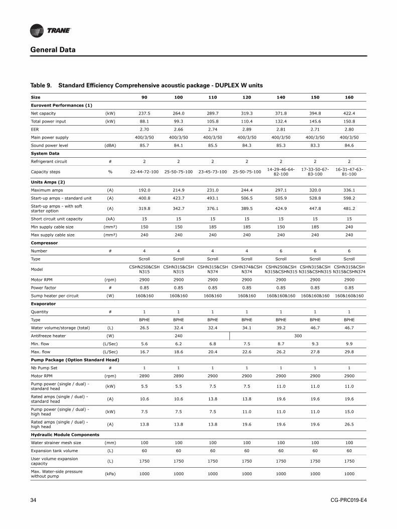
Table 9. Standard Efficiency Comprehensive acoustic package - DUPLEX W units
Size 90 100 110 120 140 150 160
Eurovent Performances (1)
Net capacity (kW) 237.5 264.0 289.7 319.3 371.8 394.8 422.4
Total power input (kW) 88.1 99.3 105.8 110.4 132.4 145.6 150.8
EER 2.70 2.66 2.74 2.89 2.81 2.71 2.80
Main power supply 400/3/50 400/3/50 400/3/50 400/3/50 400/3/50 400/3/50 400/3/50
Sound power level (dBA) 85.7 84.1 85.5 84.3 85.3 83.3 84.6
System Data
Refrigerant circuit # 2 2 2 2 2 2 2
Capacity steps % 22-44-72-100 25-50-75-100 23-45-73-100 25-50-75-10014-29-46-64-
82-10017-33-50-67-
83-10016-31-47-63-81-100
Units Amps (2)
Maximum amps (A) 192.0 214.9 231.0 244.4 297.1 320.0 336.1
Start-up amps - standard unit (A) 400.8 423.7 493.1 506.5 505.9 528.8 598.2
Start-up amps - with soft starter option
(A) 319.8 342.7 376.1 389.5 424.9 447.8 481.2
Short circuit unit capacity (kA) 15 15 15 15 15 15 15
Min supply cable size (mm²) 150 150 185 185 150 185 240
Max supply cable size (mm²) 240 240 240 240 240 240 240
Compressor
Number # 4 4 4 4 6 6 6
Type Scroll Scroll Scroll Scroll Scroll Scroll Scroll
ModelCSHN250&CSH
N315CSHN315&CSH
N315CSHN315&CSH
N374CSHN374&CSH
N374CSHN250&CSHN315&CSHN315
CSHN315&CSHN315&CSHN315
CSHN315&CSHN315&CSHN374
Motor RPM (rpm) 2900 2900 2900 2900 2900 2900 2900
Power factor # 0.85 0.85 0.85 0.85 0.85 0.85 0.85
Sump heater per circuit (W) 160&160 160&160 160&160 160&160 160&160&160 160&160&160 160&160&160
Evaporator
Quantity # 1 1 1 1 1 1 1
Type BPHE BPHE BPHE BPHE BPHE BPHE BPHE
Water volume/storage (total) (L) 26.5 32.4 32.4 34.1 39.2 46.7 46.7
Antifreeze heater (W) 240 300
Min. flow (L/Sec) 5.6 6.2 6.8 7.5 8.7 9.3 9.9
Max. flow (L/Sec) 16.7 18.6 20.4 22.6 26.2 27.8 29.8
Pump Package (Option Standard Head)
Nb Pump Set # 1 1 1 1 1 1 1
Motor RPM (rpm) 2890 2890 2900 2900 2900 2900 2900
Pump power (single / dual) - standard head
(kW) 5.5 5.5 7.5 7.5 11.0 11.0 11.0
Rated amps (single / dual) - standard head
(A) 10.6 10.6 13.8 13.8 19.6 19.6 19.6
Pump power (single / dual) - high head
(kW) 7.5 7.5 7.5 11.0 11.0 11.0 15.0
Rated amps (single / dual) - high head
(A) 13.8 13.8 13.8 19.6 19.6 19.6 26.5
Hydraulic Module Components
Water strainer mesh size (mm) 100 100 100 100 100 100 100
Expansion tank volume (L) 60 60 60 60 60 60 60
User volume expansion capacity
(L) 1750 1750 1750 1750 1750 1750 1750
Max. Water-side pressure without pump
(kPa) 1000 1000 1000 1000 1000 1000 1000

CG-PRC019-E4 35
General Data
(1) Eurovent Conditions (Evap. 12°C/7°C - Air. 35°C)
(2) amps for base unit without pump package, without freeze protection
(3) without pump package
Max. Water-side pressure with pump
(kPa) 500 500 500 500 500 500 500
Antifreeze heater (W) 240 300
Pump package anti freeze heater
(W) 1150
Water tank antifreeze heater (W) 800 1200 1200 1200 1200 1200 1200
Water tank volume (L) 592 592 592 592 762 762 762
Condenser
Type Fin and Tube Fin and Tube Fin and Tube Fin and Tube Fin and Tube Fin and Tube Fin and Tube
Qty of coils # 4 4 4 4 4 4 4
Fan
Type Propeller Propeller Propeller Propeller Propeller Propeller Propeller
Quantity per circuit # 3 3 4 4 4 4 5
Diameter (mm) 757 757 757 757 757 757 757
Drive type Direct Direct Direct Direct Direct Direct Direct
Airflow per fan (m3/h) 10292 10596 10052 9633 10168 10170 9636
Static pressure (Pa) 0 0 0 0 0 0 0
Motor rpm # 700 700 700 700 700 700 700
Unit Water Connection
Chilled water (mm) 100 100 100 100 100 100 100
Type (standard) Grooved Grooved Grooved Grooved Grooved Grooved Grooved
Dimensions
Unit length with buffer tank (mm) 3647 4230 4230 4230 5145 5145 5145
Unit length without buffer tank (mm) 3647 4230 4230 4230 5145 5145 5145
Unit width (mm) 2273 2273 2273 2273 2273 2273 2273
Unit height (mm) 2344 2344 2344 2344 2344 2344 2344
Weight
Operating weight(3) (kg) 2491 2683 2773 2916 3454 3580 3670
Shipping weight(3) (kg) 2442 2629 2719 2861 3394 3513 3602
Additional weight (single pump standard head)
(kg) 273 274 314 314 377 376 377
Additional weight (dual pump standard head)
(kg) 324 325 405 405 511 509 509
Additional weight (single pump high head)
(kg) 310 310 310 355 377 376 390
Additional weight (dual pump high head)
(kg) 406 407 407 489 511 510 537
Additional shipping weight (buffer tank)
(kg) 203 203 202 203 252 251 251
Refrigerant & Oil Charge
Refrigerant Charge (Circuit 1/Circuit 2)
(kg) 25.4/25.4 28.1/28.1 29/29 38.1/38.1 47.2/47.2 47.2/47.2 47.2/47.2
Oil Charge (Circuit 1/Circuit 2) (L) 13.4 / 13.4 13.4 / 13.4 13.9 / 13.9 14.4 / 14.4 20.1 / 20.1 20.1 / 20.1 20.6 / 20.6
Table 9. Standard Efficiency Comprehensive acoustic package - DUPLEX W units (continued)
Size 90 100 110 120 140 150 160
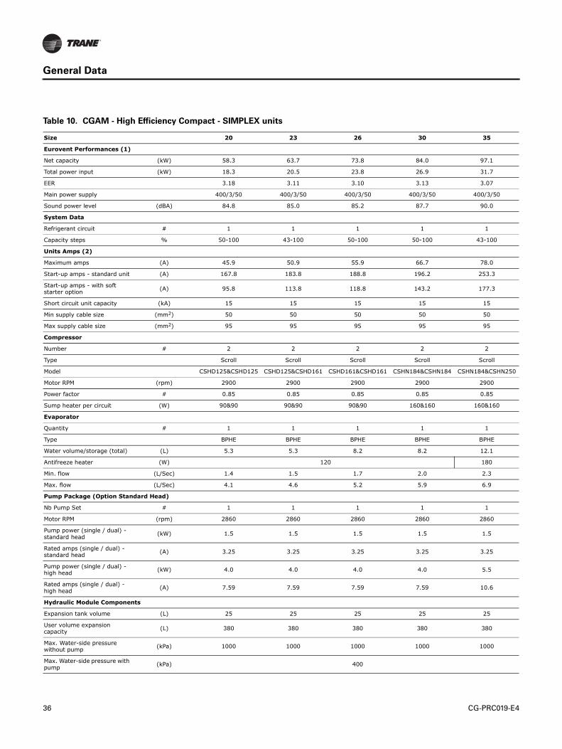
36 CG-PRC019-E4
General Data
Table 10. CGAM - High Efficiency Compact - SIMPLEX units
Size 20 23 26 30 35
Eurovent Performances (1)
Net capacity (kW) 58.3 63.7 73.8 84.0 97.1
Total power input (kW) 18.3 20.5 23.8 26.9 31.7
EER 3.18 3.11 3.10 3.13 3.07
Main power supply 400/3/50 400/3/50 400/3/50 400/3/50 400/3/50
Sound power level (dBA) 84.8 85.0 85.2 87.7 90.0
System Data
Refrigerant circuit # 1 1 1 1 1
Capacity steps % 50-100 43-100 50-100 50-100 43-100
Units Amps (2)
Maximum amps (A) 45.9 50.9 55.9 66.7 78.0
Start-up amps - standard unit (A) 167.8 183.8 188.8 196.2 253.3
Start-up amps - with soft starter option
(A) 95.8 113.8 118.8 143.2 177.3
Short circuit unit capacity (kA) 15 15 15 15 15
Min supply cable size (mm2) 50 50 50 50 50
Max supply cable size (mm2) 95 95 95 95 95
Compressor
Number # 2 2 2 2 2
Type Scroll Scroll Scroll Scroll Scroll
Model CSHD125&CSHD125 CSHD125&CSHD161 CSHD161&CSHD161 CSHN184&CSHN184 CSHN184&CSHN250
Motor RPM (rpm) 2900 2900 2900 2900 2900
Power factor # 0.85 0.85 0.85 0.85 0.85
Sump heater per circuit (W) 90&90 90&90 90&90 160&160 160&160
Evaporator
Quantity # 1 1 1 1 1
Type BPHE BPHE BPHE BPHE BPHE
Water volume/storage (total) (L) 5.3 5.3 8.2 8.2 12.1
Antifreeze heater (W) 120 180
Min. flow (L/Sec) 1.4 1.5 1.7 2.0 2.3
Max. flow (L/Sec) 4.1 4.6 5.2 5.9 6.9
Pump Package (Option Standard Head)
Nb Pump Set # 1 1 1 1 1
Motor RPM (rpm) 2860 2860 2860 2860 2860
Pump power (single / dual) - standard head
(kW) 1.5 1.5 1.5 1.5 1.5
Rated amps (single / dual) - standard head
(A) 3.25 3.25 3.25 3.25 3.25
Pump power (single / dual) - high head
(kW) 4.0 4.0 4.0 4.0 5.5
Rated amps (single / dual) - high head
(A) 7.59 7.59 7.59 7.59 10.6
Hydraulic Module Components
Expansion tank volume (L) 25 25 25 25 25
User volume expansion capacity
(L) 380 380 380 380 380
Max. Water-side pressure without pump
(kPa) 1000 1000 1000 1000 1000
Max. Water-side pressure with pump
(kPa) 400

CG-PRC019-E4 37
General Data
(1) Eurovent Conditions (Evap. 12°C/7°C - Air. 35°C)
(2) amps for base unit without pump package, without freeze protection
(3) without pump package
Antifreeze heater (W) 180
Pump package anti freeze heater
(W) 530
Water tank antifreeze heater (W) 860
Water tank volume (L) 500
Condenser
Type Fin and Tube Fin and Tube Fin and Tube Fin and Tube Fin and Tube
Qty of coils # 1 1 1 1 1
Fan
Type Propeller Propeller Propeller Propeller Propeller
Quantity per circuit # 2 2 2 3 3
Diameter (mm) 757 757 757 757 757
Drive type Direct Direct Direct Direct Direct
Airflow per fan (m3/h) 13341 13344 13347 13129 13133
Static pressure (Pa) 0 0 0 0 0
Motor rpm # 920 920 920 920 920
Unit Water Connection
Chilled water (mm) 50 50 50 65 65
Type (standard) Grooved Grooved Grooved Grooved Grooved
Dimensions
Unit length with buffer tank (mm) 3340 3340 3340 4254 4254
Unit length without buffer tank (mm) 2890 2890 2890 3804 3804
Unit width (mm) 1280 1280 1280 1280 1280
Unit height (mm) 2145 2145 2145 2145 2145
Weight
Operating weight(3) (kg) 888 887 902 1105 1161
Shipping weight(3) (kg) 860 860 873 1074 1128
Additional weight (single pump standard head)
(kg) 154 153 154 195 195
Additional weight (dual pump standard head)
(kg) 184 183 183 225 225
Additional weight (single pump high head)
(kg) 163 163 162 205 208
Additional weight (dual pump high head)
(kg) 200 199 199 241 255
Additional shipping weight (buffer tank)
(kg) 326 326 326 326 326
Refrigerant & Oil Charge
Refrigerant Charge (Circuit 1/Circuit 2)
(kg) 14.5 14.5 15.4 21.8 21.8
Oil Charge (Circuit 1/Circuit 2) (L) 6.6 6.6 6.6 13.4 13.4
Table 10. CGAM - High Efficiency Compact - SIMPLEX units (continued)
Size 20 23 26 30 35
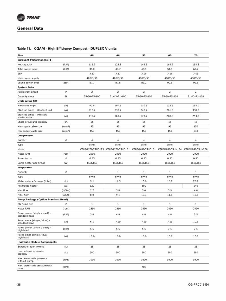
38 CG-PRC019-E4
General Data
Table 11. CGAM - High Efficiency Compact - DUPLEX V units
Size 40 46 52 60 70
Eurovent Performances (1)
Net capacity (kW) 112.9 128.8 143.5 163.9 193.8
Total power input (kW) 36.0 40.7 46.9 51.9 62.7
EER 3.13 3.17 3.06 3.16 3.09
Main power supply 400/3/50 400/3/50 400/3/50 400/3/50 400/3/50
Sound power level (dBA) 87.7 87.8 88.2 90.5 92.8
System Data
Refrigerant circuit # 2 2 2 2 2
Capacity steps % 25-50-75-100 21-43-71-100 25-50-75-100 25-50-75-100 21-43-71-100
Units Amps (2)
Maximum amps (A) 90.8 100.8 110.8 132.3 155.0
Start-up amps - standard unit (A) 212.7 233.7 243.7 261.8 330.3
Start-up amps - with soft starter option
(A) 140.7 163.7 173.7 208.8 254.3
Short circuit unit capacity (kA) 15 15 15 15 15
Min supply cable size (mm²) 95 95 95 95 150
Max supply cable size (mm²) 150 150 150 150 240
Compressor
Number # 4 4 4 4 4
Type Scroll Scroll Scroll Scroll Scroll
Model CSHD125&CSHD125 CSHD125&CSHD161 CSHD161&CSHD161 CSHN184&CSHN184 CSHN184&CSHN250
Motor RPM (rpm) 2900 2900 2900 2900 2900
Power factor # 0.85 0.85 0.85 0.85 0.85
Sump heater per circuit (W) 160&160 160&160 160&160 160&160 160&160
Evaporator
Quantity # 1 1 1 1 1
Type BPHE BPHE BPHE BPHE BPHE
Water volume/storage (total) (L) 9.1 14.3 15.6 18.9 28.2
Antifreeze heater (W) 120 180 240
Min. flow (L/Sec) 2.7 3.0 3.4 3.9 4.6
Max. flow (L/Sec) 8.0 9.1 10.3 11.8 13.8
Pump Package (Option Standard Head)
Nb Pump Set # 1 1 1 1 1
Motor RPM (rpm) 2890 2890 2890 2890 2890
Pump power (single / dual) - standard head
(kW) 3.0 4.0 4.0 4.0 5.5
Rated amps (single / dual) - standard head
(A) 6.1 7.59 7.59 7.59 10.6
Pump power (single / dual) - high head
(kW) 5.5 5.5 5.5 7.5 7.5
Rated amps (single / dual) - high head
(A) 10.6 10.6 10.6 13.8 13.8
Hydraulic Module Components
Expansion tank volume (L) 25 25 25 25 25
User volume expansion capacity
(L) 380 380 380 380 380
Max. Water-side pressure without pump
(kPa) 1000 1000 1000 1000 1000
Max. Water-side pressure with pump
(kPa) 400

CG-PRC019-E4 39
General Data
(1) Eurovent Conditions (Evap. 12°C/7°C - Air. 35°C)
(2) amps for base unit without pump package, without freeze protection
(3) without pump package
Antifreeze heater (W) 120
Pump package anti freeze heater
(W) 910
Water tank antifreeze heater (W) 800
Water tank volume (L) 515 515 515 515 515
Condenser
Type Fin and Tube Fin and Tube Fin and Tube Fin and Tube Fin and Tube
Qty of coils # 2 2 2 2 2
Fan
Type Propeller Propeller Propeller Propeller Propeller
Quantity per circuit # 2 2 2 3 3
Diameter (mm) 757 757 757 757 757
Drive type Direct Direct Direct Direct Direct
Airflow per fan (m3/h) 13341 13344 13347 13129 13133
Static pressure (Pa) 0 0 0 0 0
Motor rpm # 920 920 920 920 920
Unit Water Connection
Chilled water (mm) 65 65 80 80 80
Type (standard) Grooved Grooved Grooved Grooved Grooved
Dimensions
Unit length with buffer tank (mm) 3271 3271 3271 4185 4185
Unit length without buffer tank (mm) 2905 2905 2905 3819 3819
Unit width (mm) 2266 2266 2266 2266 2266
Unit height (mm) 2150 2150 2150 2150 2150
Weight
Operating weight(3) (kg) 1558 1573 1598 1996 2070
Shipping weight(3) (kg) 1526 1539 1560 1955 2026
Additional weight (single pump standard head)
(kg) 171 177 178 179 187
Additional weight (dual pump standard head)
(kg) 209 221 221 222 237
Additional weight (single pump high head)
(kg) 179 179 179 222 223
Additional weight (dual pump high head)
(kg) 225 226 226 318 319
Additional shipping weight (buffer tank)
(kg) 382 381 381 381 381
Refrigerant & Oil Charge
Refrigerant Charge (Circuit 1/Circuit 2)
(kg) 14.5/14.5 14.5/14.5 14.5/14.5 21.8/21.8 21.8/21.8
Oil Charge (Circuit 1/Circuit 2) (L) 6.6 / 6.6 6.6 / 6.6 6.6 / 6.6 13.4 / 13.4 13.4 / 13.4
Table 11. CGAM - High Efficiency Compact - DUPLEX V units (continued)
Size 40 46 52 60 70
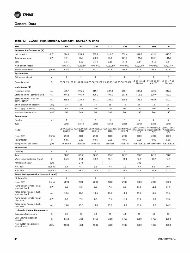
40 CG-PRC019-E4
General Data
Table 12. CGAM - High Efficiency Compact - DUPLEX W units
Size 80 90 100 110 120 140 150 160
Eurovent Performances (1)
Net capacity (kW) 224.1 254.6 282.8 311.7 332.4 391.7 419.2 443.3
Total power input (kW) 72.1 80.0 89.9 97.6 107.3 124.6 133.1 141.2
EER 3.11 3.18 3.14 3.19 3.10 3.14 3.15 3.14
Main power supply 400/3/50 400/3/50 400/3/50 400/3/50 400/3/50 400/3/50 400/3/50 400/3/50
Sound power level (dBA) 93.8 92.6 91.1 91.8 92.6 93.8 92.7 93.4
System Data
Refrigerant circuit # 2 2 2 2 2 2 2 2
Capacity steps % 25-50-75-100 22-44-72-100 25-50-75-100 23-45-73-100 25-50-75-10014-29-46-64-
82-10017-33-50-67-
83-10016-31-47-63-81-100
Units Amps (2)
Maximum amps (A) 169.4 196.5 219.4 237.0 250.4 307.3 330.2 347.8
Start-up amps - standard unit (A) 344.6 405.3 428.2 499.1 512.5 516.1 539.0 609.9
Start-up amps - with soft starter option
(A) 268.6 324.3 347.2 382.1 395.5 435.1 458.0 492.9
Short circuit unit capacity (kA) 15 15 15 15 15 15 15 15
Min supply cable size (mm²) 95 150 150 150 185 240 240 240
Max supply cable size (mm²) 240 240 240 240 240 240 240 240
Compressor
Number # 4 4 4 4 4 6 6 6
Type Scroll Scroll Scroll Scroll Scroll Scroll Scroll Scroll
ModelCSHN250&CS
HN250CSHN250&CS
HN315CSHN315&CS
HN315CSHN315&CS
HN374CSHN374&CS
HN374
CSHN250&CSHN315&CSHN
315
CSHN315&CSHN315&CSHN
315
CSHN315&CSHN315&CSHN
374
Motor RPM (rpm) 2900 2900 2900 2900 2900 2900 2900 2900
Power factor # 0.85 0.85 0.85 0.85 0.85 0.85 0.85 0.85
Sump heater per circuit (W) 160&160 160&160 160&160 160&160 160&160 160&160&160 160&160&160 160&160&160
Evaporator
Quantity # 1 1 1 1 1 1 1 1
Type BPHE BPHE BPHE BPHE BPHE BPHE BPHE BPHE
Water volume/storage (total) (L) 26.5 34.1 39.2 43.4 43.4 46.7 46.7 46.7
Antifreeze heater (W) 240 300
Min. flow (L/Sec) 5.4 6.1 6.8 7.4 7.9 9.3 9.9 10.4
Max. flow (L/Sec) 16.2 18.2 20.5 22.2 23.7 27.8 29.8 31.3
Pump Package (Option Standard Head)
Nb Pump Set # 1 1 1 1 1 1 1 1
Motor RPM (rpm) 2890 2890 2890 2900 2900 2900 2900 2900
Pump power (single / dual) - standard head
(kW) 5.5 5.5 5.5 7.5 7.5 11.0 11.0 11.0
Rated amps (single / dual) - standard head
(A) 10.6 10.6 10.6 13.8 13.8 19.6 19.6 19.6
Pump power (single / dual) - high head
(kW) 7.5 7.5 7.5 7.5 11.0 11.0 11.0 15.0
Rated amps (single / dual) - high head
(A) 13.8 13.8 13.8 13.8 19.6 19.6 19.6 26.5
Hydraulic Module Components
Expansion tank volume (L) 60 60 60 60 60 60 60 60
User volume expansion capacity
(L) 1750 1750 1750 1750 1750 1750 1750 1750
Max. Water-side pressure without pump
(kPa) 1000 1000 1000 1000 1000 1000 1000 1000
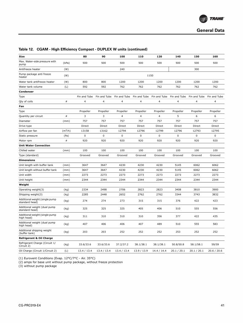
CG-PRC019-E4 41
General Data
(1) Eurovent Conditions (Evap. 12°C/7°C - Air. 35°C)
(2) amps for base unit without pump package, without freeze protection
(3) without pump package
Max. Water-side pressure with pump
(kPa) 500 500 500 500 500 500 500 500
Antifreeze heater (W) 240 300
Pump package anti freeze heater
(W) 1150
Water tank antifreeze heater (W) 800 800 1200 1200 1200 1200 1200 1200
Water tank volume (L) 592 592 762 762 762 762 762 762
Condenser
Type Fin and Tube Fin and Tube Fin and Tube Fin and Tube Fin and Tube Fin and Tube Fin and Tube Fin and Tube
Qty of coils # 4 4 4 4 4 4 4 4
Fan
Type Propeller Propeller Propeller Propeller Propeller Propeller Propeller Propeller
Quantity per circuit # 3 3 4 4 4 5 6 6
Diameter (mm) 757 757 757 757 757 757 757 757
Drive type Direct Direct Direct Direct Direct Direct Direct Direct
Airflow per fan (m3/h) 13158 13162 12794 12796 12799 12796 12793 12795
Static pressure (Pa) 0 0 0 0 0 0 0 0
Motor rpm # 920 920 920 920 920 920 920 920
Unit Water Connection
Chilled water (mm) 100 100 100 100 100 100 100 100
Type (standard) Grooved Grooved Grooved Grooved Grooved Grooved Grooved Grooved
Dimensions
Unit length with buffer tank (mm) 3647 3647 4230 4230 4230 5145 6062 6062
Unit length without buffer tank (mm) 3647 3647 4230 4230 4230 5145 6062 6062
Unit width (mm) 2273 2273 2273 2273 2273 2273 2273 2273
Unit height (mm) 2344 2344 2344 2344 2344 2344 2344 2344
Weight
Operating weight(3) (kg) 2334 2498 2706 2823 2823 3408 3810 3900
Shipping weight(3) (kg) 2285 2448 2652 2762 2762 3344 3743 3832
Additional weight (single pump standard head)
(kg) 274 274 273 315 315 376 422 423
Additional weight (dual pump standard head)
(kg) 325 325 325 405 406 510 555 556
Additional weight (single pump high head)
(kg) 311 310 310 310 356 377 422 435
Additional weight (dual pump high head)
(kg) 407 406 406 407 489 510 555 583
Additional shipping weight (buffer tank)
(kg) 203 203 252 252 252 253 252 252
Refrigerant & Oil Charge
Refrigerant Charge (Circuit 1/Circuit 2)
(kg) 33.6/33.6 33.6/33.6 37.2/37.2 38.1/38.1 38.1/38.1 50.8/50.8 58.1/58.1 59/59
Oil Charge (Circuit 1/Circuit 2) (L) 13.4 / 13.4 13.4 / 13.4 13.4 / 13.4 13.9 / 13.9 14.4 / 14.4 20.1 / 20.1 20.1 / 20.1 20.6 / 20.6
Table 12. CGAM - High Efficiency Compact - DUPLEX W units (continued)
Size 80 90 100 110 120 140 150 160

42 CG-PRC019-E4
General Data
Table 13. CGAM - High Efficiency Super Quiet - SIMPLEX units
Size 20 23 26 30 35
Eurovent Performances (1)
Net capacity (kW) 58.1 63.7 73.8 82.1 97.0
Total power input (kW) 18.4 20.4 23.8 26.5 31.7
EER 3.15 3.12 3.10 3.10 3.06
Main power supply 400/3/50 400/3/50 400/3/50 400/3/50 400/3/50
Sound power level (dBA) 79.5 79.5 79.6 81.8 83.9
System Data
Refrigerant circuit # 1 1 1 1 1
Capacity steps % 50-100 43-100 50-100 50-100 43-100
Units Amps (2)
Maximum amps (A) 45.9 50.9 55.9 66.7 78.0
Start-up amps - standard unit (A) 167.8 183.8 188.8 196.2 253.3
Start-up amps - with soft starter option
(A) 95.8 113.8 118.8 143.2 177.3
Short circuit unit capacity (kA) 15 15 15 15 15
Min supply cable size (mm²) 50 50 50 50 50
Max supply cable size (mm²) 95 95 95 95 95
Compressor
Number # 2 2 2 2 2
Type Scroll Scroll Scroll Scroll Scroll
Model CSHD125&CSHD125 CSHD125&CSHD161 CSHD161&CSHD161 CSHN184&CSHN184 CSHN184&CSHN250
Motor RPM (rpm) 2900 2900 2900 2900 2900
Power factor # 0.85 0.85 0.85 0.85 0.85
Sump heater per circuit (W) 90&90 90&90 90&90 160&160 160&160
Evaporator
Quantity # 1 1 1 1 1
Type BPHE BPHE BPHE BPHE BPHE
Water volume/storage (total) (L) 5.3 5.3 8.2 8.2 12.1
Antifreeze heater (W) 120 180
Min. flow (L/Sec) 1.4 1.5 1.7 2.0 2.3
Max. flow (L/Sec) 4.1 4.6 5.2 5.9 6.8
Pump Package (Option Standard Head)
Nb Pump Set # 1 1 1 1 1
Motor RPM (rpm) 2860 2860 2860 2860 2860
Pump power (single / dual) - standard head
(kW) 1.5 1.5 1.5 1.5 1.5
Rated amps (single / dual) - standard head
(A) 3.25 3.25 3.25 3.25 3.25
Pump power (single / dual) - high head
(kW) 4.0 4.0 4.0 4.0 5.5
Rated amps (single / dual) - high head
(A) 7.59 7.59 7.59 7.59 10.6
Hydraulic Module Components
Expansion tank volume (L) 25 25 25 25 25
User volume expansion capacity
(L) 380 380 380 380 380
Max. Water-side pressure without pump
(kPa) 1000 1000 1000 1000 1000
Max. Water-side pressure with pump
(kPa) 400

CG-PRC019-E4 43
General Data
(1) Eurovent Conditions (Evap. 12°C/7°C - Air. 35°C)
(2) amps for base unit without pump package, without freeze protection
(3) without pump package
Antifreeze heater (W) 180
Pump package anti freeze heater
(W) 530
Water tank antifreeze heater (W) 860
Water tank volume (L) 500
Condenser
Type Fin and Tube Fin and Tube Fin and Tube Fin and Tube Fin and Tube
Qty of coils # 1 1 1 1 1
Fan
Type Propeller Propeller Propeller Propeller Propeller
Quantity per circuit # 2 2 2 3 3
Diameter (mm) 732 732 732 732 732
Drive type Direct Direct Direct Direct Direct
Airflow per fan (m3/h) 13245 13249 13254 12890 12896
Static pressure (Pa) 0 0 0 0 0
Motor rpm # 700 700 700 700 700
Unit Water Connection
Chilled water (mm) 50 50 50 65 65
Type (standard) Grooved Grooved Grooved Grooved Grooved
Dimensions
Unit length with buffer tank (mm) 3340 3340 3340 4254 4254
Unit length without buffer tank (mm) 2890 2890 2890 3804 3804
Unit width (mm) 1280 1280 1280 1280 1280
Unit height (mm) 2145 2145 2145 2145 2145
Weight
Operating weight(3) (kg) 888 887 902 1105 1161
Shipping weight(3) (kg) 860 860 873 1074 1128
Additional weight (single pump standard head)
(kg) 154 153 154 195 195
Additional weight (dual pump standard head)
(kg) 184 183 183 225 225
Additional weight (single pump high head)
(kg) 163 163 162 205 208
Additional weight (dual pump high head)
(kg) 200 199 199 241 255
Additional shipping weight (buffer tank)
(kg) 326 326 326 326 326
Refrigerant & Oil Charge
Refrigerant Charge (Circuit 1/Circuit 2)
(kg) 15.4 15.4 15.4 21.8 21.8
Oil Charge (Circuit 1/Circuit 2) (L) 6.6 6.6 6.6 13.4 13.4
Table 13. CGAM - High Efficiency Super Quiet - SIMPLEX units (continued)
Size 20 23 26 30 35

44 CG-PRC019-E4
General Data
Table 14. CGAM - High Efficiency Super Quiet - DUPLEX V units
Size 40 46 52 60 70
Eurovent Performances (1)
Net capacity (kW) 112.5 128.7 143.4 164.1 193.5
Total power input (kW) 36.2 40.7 46.9 52.3 62.8
EER 3.11 3.17 3.06 3.14 3.08
Main power supply 400/3/50 400/3/50 400/3/50 400/3/50 400/3/50
Sound power level (dBA) 82.5 82.3 82.5 84.9 87.0
System Data
Refrigerant circuit # 2 2 2 2 2
Capacity steps % 25-50-75-100 21-43-71-100 25-50-75-100 25-50-75-100 21-43-71-100
Units Amps (2)
Maximum amps (A) 90.8 100.8 110.8 132.3 155.0
Start-up amps - standard unit (A) 212.7 233.7 243.7 261.8 330.3
Start-up amps - with soft starter option
(A) 140.7 163.7 173.7 208.8 254.3
Short circuit unit capacity (kA) 15 15 15 15 15
Min supply cable size (mm2) 95 95 95 95 150
Max supply cable size (mm2) 150 150 150 150 240
Compressor
Number # 4 4 4 4 4
Type Scroll Scroll Scroll Scroll Scroll
Model CSHD125&CSHD125 CSHD125&CSHD161 CSHD161&CSHD161 CSHN184&CSHN184 CSHN184&CSHN250
Motor RPM (rpm) 2900 2900 2900 2900 2900
Power factor # 0.85 0.85 0.85 0.85 0.85
Sump heater per circuit (W) 160&160 160&160 160&160 160&160 160&160
Evaporator
Quantity # 1 1 1 1 1
Type BPHE BPHE BPHE BPHE BPHE
Water volume/storage (total) (L) 9.1 14.3 15.6 18.9 28.2
Antifreeze heater (W) 120 180 240
Min. flow (L/Sec) 2.7 3.0 3.4 3.9 4.6
Max. flow (L/Sec) 8.0 9.1 10.3 11.8 13.8
Pump Package (Option Standard Head)
Nb Pump Set # 1 1 1 1 1
Motor RPM (rpm) 2890 2890 2890 2890 2890
Pump power (single / dual) - standard head
(kW) 3.0 4.0 4.0 4.0 5.5
Rated amps (single / dual) - standard head
(A) 6.1 7.59 7.59 7.59 10.6
Pump power (single / dual) - high head
(kW) 5.5 5.5 5.5 7.5 7.5
Rated amps (single / dual) - high head
(A) 10.6 10.6 10.6 13.8 13.8
Hydraulic Module Components
Expansion tank volume (L) 25 25 25 25 25
User volume expansion capacity
(L) 380 380 380 380 380
Max. Water-side pressure without pump
(kPa) 1000 1000 1000 1000 1000
Max. Water-side pressure with pump
(kPa) 400

CG-PRC019-E4 45
General Data
(1) Eurovent Conditions (Evap. 12°C/7°C - Air. 35°C)
(2) amps for base unit without pump package, without freeze protection
(3) without pump package
Antifreeze heater (W) 120
Pump package anti freeze heater
(W) 910
Water tank antifreeze heater (W) 800
Water tank volume (L) 515 515 515 515 515
Condenser
Type Fin and Tube Fin and Tube Fin and Tube Fin and Tube Fin and Tube
Qty of coils # 2 2 2 2 2
Fan
Type Propeller Propeller Propeller Propeller Propeller
Quantity per circuit # 2 2 2 3 3
Diameter (mm) 732 732 732 732 732
Drive type Direct Direct Direct Direct Direct
Airflow per fan (m3/h) 13244 13248 13254 12890 12896
Static pressure (Pa) 0 0 0 0 0
Motor rpm # 700 700 700 700 700
Unit Water Connection
Chilled water (mm) 65 65 80 80 80
Type (standard) Grooved Grooved Grooved Grooved Grooved
Dimensions
Unit length with buffer tank (mm) 3271 3271 3271 4185 4185
Unit length without buffer tank (mm) 2905 2905 2905 3819 3819
Unit width (mm) 2266 2266 2266 2266 2266
Unit height (mm) 2150 2150 2150 2150 2150
Weight
Operating weight(3) (kg) 1558 1573 1598 1996 2070
Shipping weight(3) (kg) 1526 1539 1560 1955 2026
Additional weight (single pump standard head)
(kg) 171 177 178 179 187
Additional weight (dual pump standard head)
(kg) 209 221 221 222 237
Additional weight (single pump high head)
(kg) 179 179 179 222 223
Additional weight (dual pump high head)
(kg) 225 226 226 318 319
Additional shipping weight (buffer tank)
(kg) 382 381 381 381 381
Refrigerant & Oil Charge
Refrigerant Charge (Circuit 1/Circuit 2)
(kg) 14.5/14.5 14.5/14.5 14.5/14.5 21.8/21.8 21.8/21.8
Oil Charge (Circuit 1/Circuit 2) (L) 6.6 / 6.6 6.6 / 6.6 6.6 / 6.6 13.4 / 13.4 13.4 / 13.4
Table 14. CGAM - High Efficiency Super Quiet - DUPLEX V units (continued)
Size 40 46 52 60 70

46 CG-PRC019-E4
General Data
Table 15. CGAM - High Efficiency Super Quiet - DUPLEX W units
Size 80 90 100 110 120 140 150 160
Eurovent Performances (1)
Net capacity (kW) 225.1 254.8 283.4 311.7 332.3 391.6 419.7 443.2
Total power input (kW) 71.5 79.8 89.4 97.5 107.1 124.4 132.7 140.8
EER 3.15 3.19 3.17 3.20 3.10 3.15 3.16 3.15
Main power supply 400/3/50 400/3/50 400/3/50 400/3/50 400/3/50 400/3/50 400/3/50 400/3/50
Sound power level (dBA) 87.8 86.6 85.4 86.5 87.3 87.9 86.7 87.9
System Data
Refrigerant circuit # 2 2 2 2 2 2 2 2
Capacity steps % 25-50-75-100 22-44-72-100 25-50-75-100 23-45-73-100 25-50-75-10014-29-46-64-82-100
17-33-50-67-83-100
16-31-47-63-81-100
Units Amps (2)
Maximum amps (A) 169.4 196.5 219.4 237.0 250.4 307.3 330.2 347.8
Start-up amps - standard unit (A) 344.6 405.3 428.2 499.1 512.5 516.1 539.0 609.9
Start-up amps - with soft starter option
(A) 268.6 324.3 347.2 382.1 395.5 435.1 458.0 492.9
Short circuit unit capacity (kA) 15 15 15 15 15 15 15 15
Min supply cable size (mm2) 95 150 150 150 185 240 240 240
Max supply cable size (mm2) 240 240 240 240 240 240 240 240
Compressor
Number # 4 4 4 4 4 6 6 6
Type Scroll Scroll Scroll Scroll Scroll Scroll Scroll Scroll
ModelCSHN250&CS
HN250CSHN250&CS
HN315CSHN315&CS
HN315CSHN315&CS
HN374CSHN374&CS
HN374
CSHN250&CSHN315&CSHN
315
CSHN315&CSHN315&CSHN
315
CSHN315&CSHN315&CSHN
374
Motor RPM (rpm) 2900 2900 2900 2900 2900 2900 2900 2900
Power factor # 0.85 0.85 0.85 0.85 0.85 0.85 0.85 0.85
Sump heater per circuit (W) 160&160 160&160 160&160 160&160 160&160 160&160&160 160&160&160 160&160&160
Evaporator
Quantity # 1 1 1 1 1 1 1 1
Type BPHE BPHE BPHE BPHE BPHE BPHE BPHE BPHE
Water volume/storage (total) (L) 26.5 34.1 39.2 43.4 43.4 46.7 46.7 46.7
Antifreeze heater (W) 240 300
Min. flow (L/Sec) 5.4 6.1 6.8 7.4 7.9 9.2 9.9 10.4
Max. flow (L/Sec) 16.2 18.2 20.5 22.2 23.7 27.7 29.6 31.3
Pump Package (Option Standard Head)
Nb Pump Set # 1 1 1 1 1 1 1 1
Motor RPM (rpm) 2890 2890 2890 2900 2900 2900 2900 2900
Pump power (single / dual) - standard head
(kW) 5.5 5.5 5.5 7.5 7.5 11.0 11.0 11.0
Rated amps (single / dual) - standard head
(A) 10.6 10.6 10.6 13.8 13.8 19.6 19.6 19.6
Pump power (single / dual) - high head
(kW) 7.5 7.5 7.5 7.5 11.0 11.0 11.0 15.0
Rated amps (single / dual) - high head
(A) 13.8 13.8 13.8 13.8 19.6 19.6 19.6 26.5
Hydraulic Module Components
Expansion tank volume (L) 60 60 60 60 60 60 60 60
User volume expansion capacity
(L) 1750 1750 1750 1750 1750 1750 1750 1750
Max. Water-side pressure without pump
(kPa) 1000 1000 1000 1000 1000 1000 1000 1000
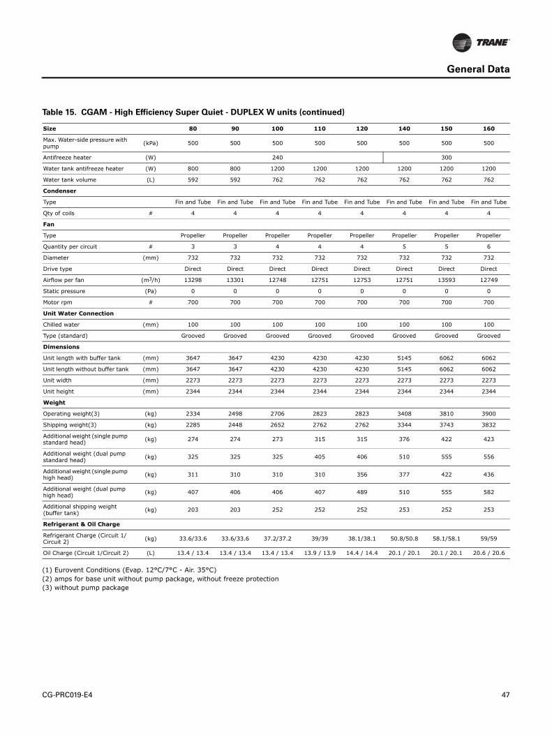
CG-PRC019-E4 47
General Data
(1) Eurovent Conditions (Evap. 12°C/7°C - Air. 35°C)
(2) amps for base unit without pump package, without freeze protection
(3) without pump package
Max. Water-side pressure with pump
(kPa) 500 500 500 500 500 500 500 500
Antifreeze heater (W) 240 300
Water tank antifreeze heater (W) 800 800 1200 1200 1200 1200 1200 1200
Water tank volume (L) 592 592 762 762 762 762 762 762
Condenser
Type Fin and Tube Fin and Tube Fin and Tube Fin and Tube Fin and Tube Fin and Tube Fin and Tube Fin and Tube
Qty of coils # 4 4 4 4 4 4 4 4
Fan
Type Propeller Propeller Propeller Propeller Propeller Propeller Propeller Propeller
Quantity per circuit # 3 3 4 4 4 5 5 6
Diameter (mm) 732 732 732 732 732 732 732 732
Drive type Direct Direct Direct Direct Direct Direct Direct Direct
Airflow per fan (m3/h) 13298 13301 12748 12751 12753 12751 13593 12749
Static pressure (Pa) 0 0 0 0 0 0 0 0
Motor rpm # 700 700 700 700 700 700 700 700
Unit Water Connection
Chilled water (mm) 100 100 100 100 100 100 100 100
Type (standard) Grooved Grooved Grooved Grooved Grooved Grooved Grooved Grooved
Dimensions
Unit length with buffer tank (mm) 3647 3647 4230 4230 4230 5145 6062 6062
Unit length without buffer tank (mm) 3647 3647 4230 4230 4230 5145 6062 6062
Unit width (mm) 2273 2273 2273 2273 2273 2273 2273 2273
Unit height (mm) 2344 2344 2344 2344 2344 2344 2344 2344
Weight
Operating weight(3) (kg) 2334 2498 2706 2823 2823 3408 3810 3900
Shipping weight(3) (kg) 2285 2448 2652 2762 2762 3344 3743 3832
Additional weight (single pump standard head)
(kg) 274 274 273 315 315 376 422 423
Additional weight (dual pump standard head)
(kg) 325 325 325 405 406 510 555 556
Additional weight (single pump high head)
(kg) 311 310 310 310 356 377 422 436
Additional weight (dual pump high head)
(kg) 407 406 406 407 489 510 555 582
Additional shipping weight (buffer tank)
(kg) 203 203 252 252 252 253 252 253
Refrigerant & Oil Charge
Refrigerant Charge (Circuit 1/Circuit 2)
(kg) 33.6/33.6 33.6/33.6 37.2/37.2 39/39 38.1/38.1 50.8/50.8 58.1/58.1 59/59
Oil Charge (Circuit 1/Circuit 2) (L) 13.4 / 13.4 13.4 / 13.4 13.4 / 13.4 13.9 / 13.9 14.4 / 14.4 20.1 / 20.1 20.1 / 20.1 20.6 / 20.6
Table 15. CGAM - High Efficiency Super Quiet - DUPLEX W units (continued)
Size 80 90 100 110 120 140 150 160
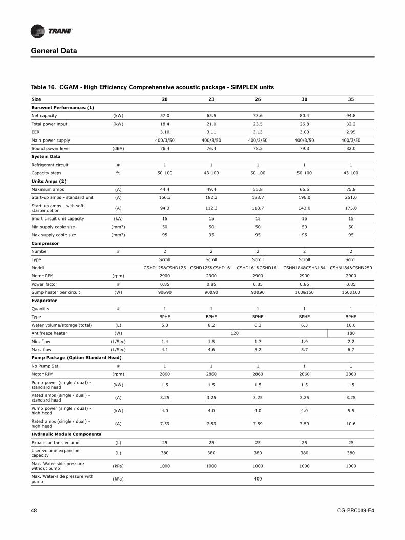
48 CG-PRC019-E4
General Data
Table 16. CGAM - High Efficiency Comprehensive acoustic package - SIMPLEX units
Size 20 23 26 30 35
Eurovent Performances (1)
Net capacity (kW) 57.0 65.5 73.6 80.4 94.8
Total power input (kW) 18.4 21.0 23.5 26.8 32.2
EER 3.10 3.11 3.13 3.00 2.95
Main power supply 400/3/50 400/3/50 400/3/50 400/3/50 400/3/50
Sound power level (dBA) 76.4 76.4 78.3 79.3 82.0
System Data
Refrigerant circuit # 1 1 1 1 1
Capacity steps % 50-100 43-100 50-100 50-100 43-100
Units Amps (2)
Maximum amps (A) 44.4 49.4 55.8 66.5 75.8
Start-up amps - standard unit (A) 166.3 182.3 188.7 196.0 251.0
Start-up amps - with soft starter option
(A) 94.3 112.3 118.7 143.0 175.0
Short circuit unit capacity (kA) 15 15 15 15 15
Min supply cable size (mm²) 50 50 50 50 50
Max supply cable size (mm²) 95 95 95 95 95
Compressor
Number # 2 2 2 2 2
Type Scroll Scroll Scroll Scroll Scroll
Model CSHD125&CSHD125 CSHD125&CSHD161 CSHD161&CSHD161 CSHN184&CSHN184 CSHN184&CSHN250
Motor RPM (rpm) 2900 2900 2900 2900 2900
Power factor # 0.85 0.85 0.85 0.85 0.85
Sump heater per circuit (W) 90&90 90&90 90&90 160&160 160&160
Evaporator
Quantity # 1 1 1 1 1
Type BPHE BPHE BPHE BPHE BPHE
Water volume/storage (total) (L) 5.3 8.2 6.3 6.3 10.6
Antifreeze heater (W) 120 180
Min. flow (L/Sec) 1.4 1.5 1.7 1.9 2.2
Max. flow (L/Sec) 4.1 4.6 5.2 5.7 6.7
Pump Package (Option Standard Head)
Nb Pump Set # 1 1 1 1 1
Motor RPM (rpm) 2860 2860 2860 2860 2860
Pump power (single / dual) - standard head
(kW) 1.5 1.5 1.5 1.5 1.5
Rated amps (single / dual) - standard head
(A) 3.25 3.25 3.25 3.25 3.25
Pump power (single / dual) - high head
(kW) 4.0 4.0 4.0 4.0 5.5
Rated amps (single / dual) - high head
(A) 7.59 7.59 7.59 7.59 10.6
Hydraulic Module Components
Expansion tank volume (L) 25 25 25 25 25
User volume expansion capacity
(L) 380 380 380 380 380
Max. Water-side pressure without pump
(kPa) 1000 1000 1000 1000 1000
Max. Water-side pressure with pump
(kPa) 400
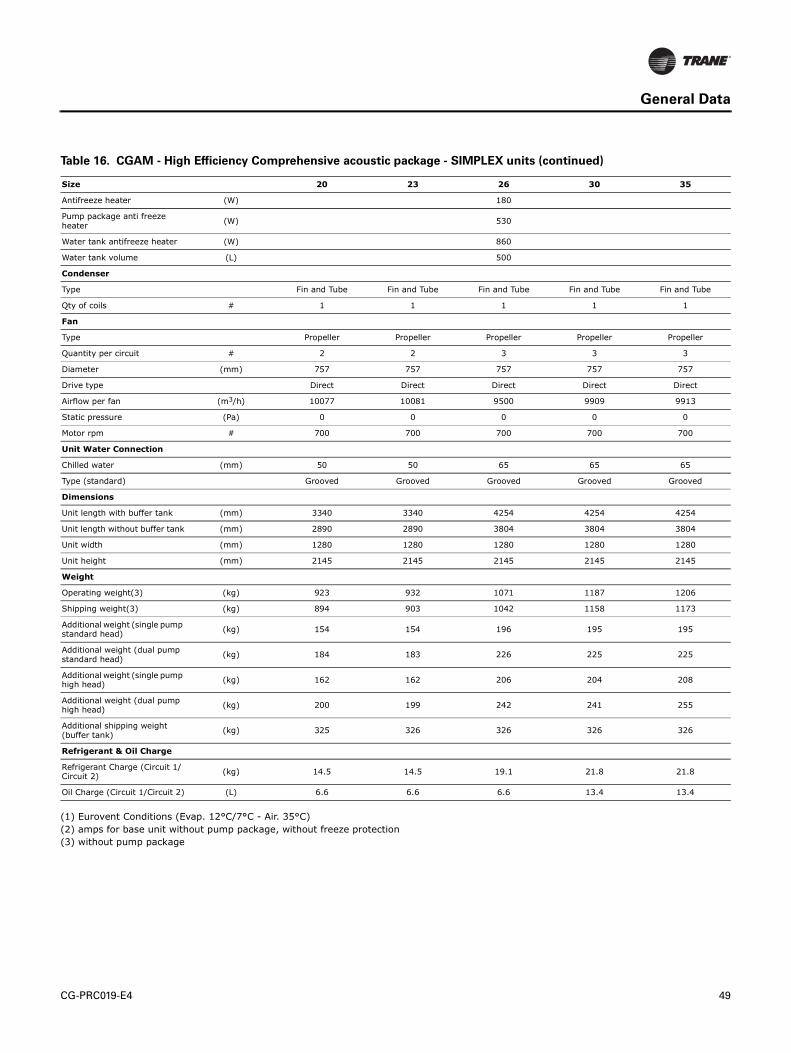
CG-PRC019-E4 49
General Data
(1) Eurovent Conditions (Evap. 12°C/7°C - Air. 35°C)
(2) amps for base unit without pump package, without freeze protection
(3) without pump package
Antifreeze heater (W) 180
Pump package anti freeze heater
(W) 530
Water tank antifreeze heater (W) 860
Water tank volume (L) 500
Condenser
Type Fin and Tube Fin and Tube Fin and Tube Fin and Tube Fin and Tube
Qty of coils # 1 1 1 1 1
Fan
Type Propeller Propeller Propeller Propeller Propeller
Quantity per circuit # 2 2 3 3 3
Diameter (mm) 757 757 757 757 757
Drive type Direct Direct Direct Direct Direct
Airflow per fan (m3/h) 10077 10081 9500 9909 9913
Static pressure (Pa) 0 0 0 0 0
Motor rpm # 700 700 700 700 700
Unit Water Connection
Chilled water (mm) 50 50 65 65 65
Type (standard) Grooved Grooved Grooved Grooved Grooved
Dimensions
Unit length with buffer tank (mm) 3340 3340 4254 4254 4254
Unit length without buffer tank (mm) 2890 2890 3804 3804 3804
Unit width (mm) 1280 1280 1280 1280 1280
Unit height (mm) 2145 2145 2145 2145 2145
Weight
Operating weight(3) (kg) 923 932 1071 1187 1206
Shipping weight(3) (kg) 894 903 1042 1158 1173
Additional weight (single pump standard head)
(kg) 154 154 196 195 195
Additional weight (dual pump standard head)
(kg) 184 183 226 225 225
Additional weight (single pump high head)
(kg) 162 162 206 204 208
Additional weight (dual pump high head)
(kg) 200 199 242 241 255
Additional shipping weight (buffer tank)
(kg) 325 326 326 326 326
Refrigerant & Oil Charge
Refrigerant Charge (Circuit 1/Circuit 2)
(kg) 14.5 14.5 19.1 21.8 21.8
Oil Charge (Circuit 1/Circuit 2) (L) 6.6 6.6 6.6 13.4 13.4
Table 16. CGAM - High Efficiency Comprehensive acoustic package - SIMPLEX units (continued)
Size 20 23 26 30 35
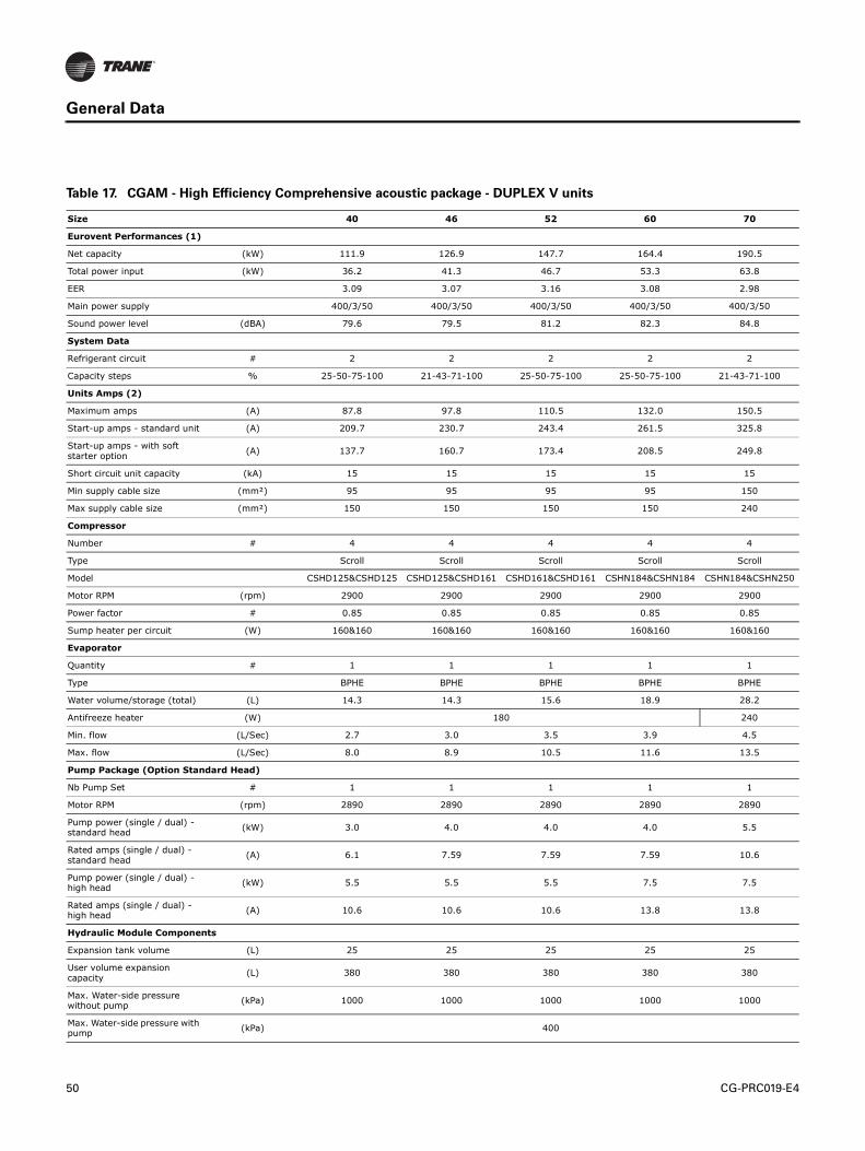
50 CG-PRC019-E4
General Data
Table 17. CGAM - High Efficiency Comprehensive acoustic package - DUPLEX V units
Size 40 46 52 60 70
Eurovent Performances (1)
Net capacity (kW) 111.9 126.9 147.7 164.4 190.5
Total power input (kW) 36.2 41.3 46.7 53.3 63.8
EER 3.09 3.07 3.16 3.08 2.98
Main power supply 400/3/50 400/3/50 400/3/50 400/3/50 400/3/50
Sound power level (dBA) 79.6 79.5 81.2 82.3 84.8
System Data
Refrigerant circuit # 2 2 2 2 2
Capacity steps % 25-50-75-100 21-43-71-100 25-50-75-100 25-50-75-100 21-43-71-100
Units Amps (2)
Maximum amps (A) 87.8 97.8 110.5 132.0 150.5
Start-up amps - standard unit (A) 209.7 230.7 243.4 261.5 325.8
Start-up amps - with soft starter option
(A) 137.7 160.7 173.4 208.5 249.8
Short circuit unit capacity (kA) 15 15 15 15 15
Min supply cable size (mm²) 95 95 95 95 150
Max supply cable size (mm²) 150 150 150 150 240
Compressor
Number # 4 4 4 4 4
Type Scroll Scroll Scroll Scroll Scroll
Model CSHD125&CSHD125 CSHD125&CSHD161 CSHD161&CSHD161 CSHN184&CSHN184 CSHN184&CSHN250
Motor RPM (rpm) 2900 2900 2900 2900 2900
Power factor # 0.85 0.85 0.85 0.85 0.85
Sump heater per circuit (W) 160&160 160&160 160&160 160&160 160&160
Evaporator
Quantity # 1 1 1 1 1
Type BPHE BPHE BPHE BPHE BPHE
Water volume/storage (total) (L) 14.3 14.3 15.6 18.9 28.2
Antifreeze heater (W) 180 240
Min. flow (L/Sec) 2.7 3.0 3.5 3.9 4.5
Max. flow (L/Sec) 8.0 8.9 10.5 11.6 13.5
Pump Package (Option Standard Head)
Nb Pump Set # 1 1 1 1 1
Motor RPM (rpm) 2890 2890 2890 2890 2890
Pump power (single / dual) - standard head
(kW) 3.0 4.0 4.0 4.0 5.5
Rated amps (single / dual) - standard head
(A) 6.1 7.59 7.59 7.59 10.6
Pump power (single / dual) - high head
(kW) 5.5 5.5 5.5 7.5 7.5
Rated amps (single / dual) - high head
(A) 10.6 10.6 10.6 13.8 13.8
Hydraulic Module Components
Expansion tank volume (L) 25 25 25 25 25
User volume expansion capacity
(L) 380 380 380 380 380
Max. Water-side pressure without pump
(kPa) 1000 1000 1000 1000 1000
Max. Water-side pressure with pump
(kPa) 400

CG-PRC019-E4 51
General Data
(1) Eurovent Conditions (Evap. 12°C/7°C - Air. 35°C)
(2) amps for base unit without pump package, without freeze protection
(3) without pump package
Antifreeze heater (W) 120
Pump package anti freeze heater
(W) 910
Water tank antifreeze heater (W) 800
Water tank volume (L) 515 515 515 515 515
Condenser
Type Fin and Tube Fin and Tube Fin and Tube Fin and Tube Fin and Tube
Qty of coils # 2 2 2 2 2
Fan
Type Propeller Propeller Propeller Propeller Propeller
Quantity per circuit # 2 2 3 3 3
Diameter (mm) 757 757 757 757 757
Drive type Direct Direct Direct Direct Direct
Airflow per fan (m3/h) 10077 10080 9500 9909 9913
Static pressure (Pa) 0 0 0 0 0
Motor rpm # 700 700 700 700 700
Unit Water Connection
Chilled water (mm) 65 65 80 80 80
Type (standard) Grooved Grooved Grooved Grooved Grooved
Dimensions
Unit length with buffer tank (mm) 3271 3271 4185 4185 4185
Unit length without buffer tank (mm) 2905 2905 3819 3819 3819
Unit width (mm) 2266 2266 2266 2266 2266
Unit height (mm) 2150 2150 2150 2150 2150
Weight
Operating weight(3) (kg) 1650 1658 1907 2150 2170
Shipping weight(3) (kg) 1613 1621 1869 2109 2124
Additional weight (single pump standard head)
(kg) 170 177 179 179 187
Additional weight (dual pump standard head)
(kg) 208 221 223 222 237
Additional weight (single pump high head)
(kg) 178 178 181 222 222
Additional weight (dual pump high head)
(kg) 225 225 228 318 319
Additional shipping weight (buffer tank)
(kg) 382 381 381 381 381
Refrigerant & Oil Charge
Refrigerant Charge (Circuit 1/Circuit 2)
(kg) 14.5/14.5 14.5/14.5 19.1/19.1 21.8/21.8 21.8/21.8
Oil Charge (Circuit 1/Circuit 2) (L) 6.6 / 6.6 6.6 / 6.6 6.6 / 6.6 13.4 / 13.4 13.4 / 13.4
Table 17. CGAM - High Efficiency Comprehensive acoustic package - DUPLEX V units (continued)
Size 40 46 52 60 70
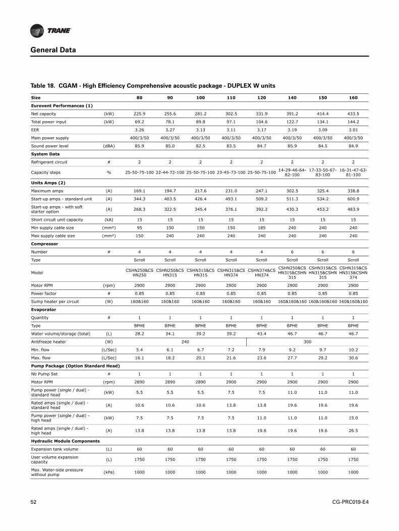
52 CG-PRC019-E4
General Data
Table 18. CGAM - High Efficiency Comprehensive acoustic package - DUPLEX W units
Size 80 90 100 110 120 140 150 160
Eurovent Performances (1)
Net capacity (kW) 225.9 255.6 281.2 302.5 331.9 391.2 414.4 433.5
Total power input (kW) 69.2 78.1 89.8 97.1 104.6 122.7 134.1 144.2
EER 3.26 3.27 3.13 3.11 3.17 3.19 3.09 3.01
Main power supply 400/3/50 400/3/50 400/3/50 400/3/50 400/3/50 400/3/50 400/3/50 400/3/50
Sound power level (dBA) 85.9 85.0 82.5 83.5 84.7 85.9 84.5 84.9
System Data
Refrigerant circuit # 2 2 2 2 2 2 2 2
Capacity steps % 25-50-75-100 22-44-72-100 25-50-75-100 23-45-73-100 25-50-75-10014-29-46-64-82-100
17-33-50-67-83-100
16-31-47-63-81-100
Units Amps (2)
Maximum amps (A) 169.1 194.7 217.6 231.0 247.1 302.5 325.4 338.8
Start-up amps - standard unit (A) 344.3 403.5 426.4 493.1 509.2 511.3 534.2 600.9
Start-up amps - with soft starter option
(A) 268.3 322.5 345.4 376.1 392.2 430.3 453.2 483.9
Short circuit unit capacity (kA) 15 15 15 15 15 15 15 15
Min supply cable size (mm²) 95 150 150 150 185 240 240 240
Max supply cable size (mm²) 150 240 240 240 240 240 240 240
Compressor
Number # 4 4 4 4 4 6 6 6
Type Scroll Scroll Scroll Scroll Scroll Scroll Scroll Scroll
ModelCSHN250&CS
HN250CSHN250&CS
HN315CSHN315&CS
HN315CSHN315&CS
HN374CSHN374&CS
HN374
CSHN250&CSHN315&CSHN
315
CSHN315&CSHN315&CSHN
315
CSHN315&CSHN315&CSHN
374
Motor RPM (rpm) 2900 2900 2900 2900 2900 2900 2900 2900
Power factor # 0.85 0.85 0.85 0.85 0.85 0.85 0.85 0.85
Sump heater per circuit (W) 160&160 160&160 160&160 160&160 160&160 160&160&160 160&160&160 160&160&160
Evaporator
Quantity # 1 1 1 1 1 1 1 1
Type BPHE BPHE BPHE BPHE BPHE BPHE BPHE BPHE
Water volume/storage (total) (L) 28.2 34.1 39.2 39.2 43.4 46.7 46.7 46.7
Antifreeze heater (W) 240 300
Min. flow (L/Sec) 5.4 6.1 6.7 7.2 7.9 9.2 9.7 10.2
Max. flow (L/Sec) 16.1 18.2 20.1 21.6 23.6 27.7 29.2 30.6
Pump Package (Option Standard Head)
Nb Pump Set # 1 1 1 1 1 1 1 1
Motor RPM (rpm) 2890 2890 2890 2900 2900 2900 2900 2900
Pump power (single / dual) - standard head
(kW) 5.5 5.5 5.5 7.5 7.5 11.0 11.0 11.0
Rated amps (single / dual) - standard head
(A) 10.6 10.6 10.6 13.8 13.8 19.6 19.6 19.6
Pump power (single / dual) - high head
(kW) 7.5 7.5 7.5 7.5 11.0 11.0 11.0 15.0
Rated amps (single / dual) - high head
(A) 13.8 13.8 13.8 13.8 19.6 19.6 19.6 26.5
Hydraulic Module Components
Expansion tank volume (L) 60 60 60 60 60 60 60 60
User volume expansion capacity
(L) 1750 1750 1750 1750 1750 1750 1750 1750
Max. Water-side pressure without pump
(kPa) 1000 1000 1000 1000 1000 1000 1000 1000

CG-PRC019-E4 53
General Data
(1) Eurovent Conditions (Evap. 12°C/7°C - Air. 35°C)
(2) amps for base unit without pump package, without freeze protection
(3) without pump package
Max. Water-side pressure with pump
(kPa) 500 500 500 500 500 500 500 500
Antifreeze heater (W) 240 300
Pump package anti freeze heater
(W) 1150
Water tank antifreeze heater (W) 1200 1200 1200 1200 1200 1200 1200 1200
Water tank volume (L) 762 762 762 762 762 762 762 762
Condenser
Type Fin and Tube Fin and Tube Fin and Tube Fin and Tube Fin and Tube Fin and Tube Fin and Tube Fin and Tube
Qty of coils # 4 4 4 4 4 4 4 4
Fan
Type Propeller Propeller Propeller Propeller Propeller Propeller Propeller Propeller
Quantity per circuit # 3 4 4 4 5 6 6 6
Diameter (mm) 757 757 757 757 757 757 757 757
Drive type Direct Direct Direct Direct Direct Direct Direct Direct
Airflow per fan (m3/h) 10291 9626 9629 10163 9627 9627 9628 9630
Static pressure (Pa) 0 0 0 0 0 0 0 0
Motor rpm # 700 700 700 700 700 700 700 700
Unit Water Connection
Chilled water (mm) 100 100 100 100 100 100 100 100
Type (standard) Grooved Grooved Grooved Grooved Grooved Grooved Grooved Grooved
Dimensions
Unit length with buffer tank (mm) 4230 4230 4230 5145 5145 6062 6062 6062
Unit length without buffer tank (mm) 4230 4230 4230 5145 5145 6062 6062 6062
Unit width (mm) 2273 2273 2273 2273 2273 2273 2273 2273
Unit height (mm) 2344 2344 2344 2344 2344 2344 2344 2344
Weight
Operating weight(3) (kg) 2598 2798 2910 3163 3280 3946 4054 4054
Shipping weight(3) (kg) 2552 2749 2856 3110 3220 3882 3986 3986
Additional weight (single pump standard head)
(kg) 274 273 274 335 337 422 423 423
Additional weight (dual pump standard head)
(kg) 324 324 324 426 428 556 556 556
Additional weight (single pump high head)
(kg) 310 310 310 332 377 423 423 436
Additional weight (dual pump high head)
(kg) 406 406 406 428 510 556 556 583
Additional shipping weight (buffer tank)
(kg) 252 252 252 252 252 252 253 252
Refrigerant & Oil Charge
Refrigerant Charge (Circuit 1/Circuit 2)
(kg) 36.3/36.3 36.3/36.3 37.2/37.2 44.5/44.5 45.4/45.4 58.1/58.1 58.1/58.1 59/59
Oil Charge (Circuit 1/Circuit 2) (L) 13.4 / 13.4 13.4 / 13.4 13.4 / 13.4 13.9 / 13.9 14.4 / 14.4 20.1 / 20.1 20.1 / 20.1 20.6 / 20.6
Table 18. CGAM - High Efficiency Comprehensive acoustic package - DUPLEX W units (continued)
Size 80 90 100 110 120 140 150 160
54 CG-PRC019-E4
Controls
LCD Touch-Screen Display with Multi-Language Support
The standard DynaView display provided with the Trane CH530 control panel features an LCD
touch-screen that is navigated by file tabs. This is an advanced interface that allows the user to
access any important information concerning setpoints, active temperatures, modes, electrical
data, pressure, and diagnostics. It uses full text display available in 18 languages.
Display Features Include:
• LCD touch-screen with LED backlighting, for scrolling access to input and output operating
information
• Single-screen, folder/tab-style display of all available information on individual components
(evaporator, condenser, compressor, etc.)
• Password entry/lockout system to enable or disable display
• Automatic and immediate stop capabilities for standard or immediate manual shutdown
• Fast, easy access to available chiller data in tabbed format, including:
• Modes of operation, including normal cooling and heating as well as ice making
• Water temperatures and setpoints
• Loading and limiting status and setpoints
• Outdoor air temperature
• Start/stop differential timers
• Pump status and override
• Chilled and hot water reset settings
• Optional external setpoints, including:
• Chilled and hot water
• Demand limit
• Ice building
CG-PRC019-E4 55
Controls
Reports, listed on a single tabbed screen for easy access, including:
• ASHRAE, containing all guideline 3 report information
• Evaporator
• Condenser
• Compressor
Evaporator, condenser, and compressor reports containing all operational information on
individual components, including:
• Water temperatures
• Refrigerant pressures, temperatures, and approach
• Flow switch status
• EXV position
• Compressor starts and run-time
Alarm and diagnostic information, including:
• Flashing alarms with touch-screen button for immediate address of alarm condition
• Scrollable list of last ten active diagnostics
• Specific information on applicable diagnostic from list of over one-hundred
• Automatic or manual resetting diagnostic types
Adaptive Controls
Adaptive Controls directly sense the control variables that govern the operation of the chiller:
evaporator pressure and condenser pressure. When any one of these variables approaches a limit
condition when damage may occur to the unit or shutdown on a safety, Adaptive Controls takes
corrective action to avoid shutdown and keep the chiller operating. This happens through
combined actions of compressor and/or fan staging. Whenever possible, the chiller is allowed to
continue making chilled or hot water. This keeps cooling capacity available unit the problem can
be solved. Overall, the safety controls help keep the building or process running and out of trouble.
56 CG-PRC019-E4
Controls
Stand-Alone Controls
Single chillers installed in applications without a building management system is simple to install
and control: only a remote auto/stop for scheduling is required for unit operation. Signals from the
chilled-water pump contactor auxiliary, or a flow switch, are wired to the chilled-water flow
interlock. Signals from a time clock or some other remote device are wired to the external auto/stop
input.
Standard Features
• Auto/Stop - A job-site provided contact closure turns the unit on and off.
• External Interlock - A job-site provided contact opening wired to this input turns the unit off and
require a manual reset of the unit microcomputer. This closure is typically triggered by a job-
site provided system such as a fire alarm.
Hardwire Points
Microcomputer controls allow simple interface with other control systems, such as time clocks,
building automation systems, and ice storage systems via hardwire points. This means you have
the flexibility to meet job requirements while not having to learn a complicated control system.
Remote devices are wired from the control panel to provide auxiliary control to a building
automation system. Inputs and outputs can be communicated via a typical 4–20 mA electrical
signal, an equivalent 2–10 Vdc signal, or by utilizing contact closures.
This setup has the same stand features as a stand-alone water chiller, with the possibility of having
additional optional features:
• Ice making control
• External chilled or hot water setpoint
• External demand limit setpoint
• Chilled water temperature reset
• Programmable relays - available outputs are: alarm-latching, alarm-auto reset, general
alarm, warning, chiller limit mode, compressor running, and Tracer control
CG-PRC019-E4 57
Controls
LonTalk LCI-C Interface with Modbus Interface
LonTalk (LCI-C) with ModBus communications capabilities are available, with communication link
via single twisted-pair wiring to factory-installed, tested communication board.
Required features:
• LonTalk LC I-C Interface w/ Modbus Interface
• Protocol Interface Controller
Modbus is a messaging structure developed by the Modicon to transfer and register data between
control devices. Modbus is a membership-based trade association that seeks to drive the adoption
of the Modbus communication protocol as the messaging structure that devices support. Modbus
is a system level communications protocol.
BACnet Interface
BACnet interface capabilities are available, with communication link via single twisted-pair wiring
to a factory-installed and tested communication board.
Required features:
• BACnet Interface (selectable option with chiller)
BACnet is a data communication protocol for building automation and control networks developed
by American Society of Heating, Refrigerating and Air-Conditioning Engineers (ASHRAE).
LonTalk LCI-C Interface
LonTalk (LCI-C) communications capabilities are available, with communication link via single
twisted-pair wiring to factory-installed, tested communication board.
Required features:
• LonTalk/Tracer Summit Interface (selectable option with chiller)
LonTalk is a communications protocol developed by the Echelon Corporation. The LonMark
association develops control profiles using the LonTalk communication protocol. LonTalk is a unit
level communications protocol.
LonTalk Communications Interface for Chillers (LCI-C) provides a generic automation system with
the LonMark chiller profile inputs/outputs. In addition to the standard points, Trane provides other
commonly used network output variables for greater interoperability with any automation system.
The complete reference list of Trane LonTalk points is available on the LonMark web site.
Trane controls or another vendor’s system can use the predefined list of points with ease to give
the operator a complete picture of how the system is running
58 CG-PRC019-E4
Controls
Tracer Summit
The chiller plant control capabilities of the Trane Tracer Summit building automation system are
unequaled in the industry. Trane’s depth of experience in chillers and controls makes us a well-
qualified choice for automation of chiller plants using air-cooled AquaStream3G chillers. Our chiller
plant automation software is fully pre-engineered and tested.
Required features:
• LonTalk/Tracer Summit Interface (selectable option with chiller)
• Building Control Unit (external device required)
Energy Efficiency
• Sequences starting of chillers to optimize the overall chiller plant energy efficiency
– Individual chillers operate as base, peak, or swing based on capacity and efficiency
– Automatically rotates individual chiller operation to equalize runtime and wear
between chillers.
– Evaluates and selects the lowest energy consumption alternative from an overall
system perspective.
Easy Operation and Maintenance
• Remote monitoring and control
• Displays both current operation conditions and scheduled automated control actions
• Concise reports assist in planning for preventative maintenance and verifying performance
• Alarm notification and diagnostic messages aid in quick and accurate troubleshooting
When integrated with a Tracer Summit building management system the total building operation
can be optimized. With this system option, the full breadth of Trane’s HVAC and controls experience
are applied to offer solutions to many facility issues. If your project calls for an interface to other
systems, Tracer Summit can share data via BACnet an open systems protocol.
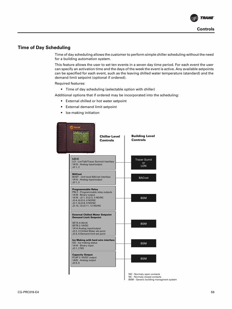
CG-PRC019-E4 59
Controls
Time of Day Scheduling
Time of day scheduling allows the customer to perform simple chiller scheduling without the need
for a building automation system.
This feature allows the user to set ten events in a seven day time period. For each event the user
can specify an activation time and the days of the week the event is active. Any available setpoints
can be specified for each event, such as the leaving chilled water temperature (standard) and the
demand limit setpoint (optional if ordered).
Required features:
• Time of day scheduling (selectable option with chiller)
Additional options that if ordered may be incorporated into the scheduling:
• External chilled or hot water setpoint
• External demand limit setpoint
• Ice-making initiation
Tracer Sumit
or
LON
BACnet
Chiller Level
Controls
Building Level
Controls
BMS
BMS
BMS
BMS
NO - Normaly open contacts
NC - Normaly closed contacts
BMS - Generic building managment system
LCI - Lon Talk/Tracer Summit Interface
1A15 - Analog input/output
J2-1, 2
BCNT - Unit level BACnet interface
1A15 - Analog input/output
J2-1, 2
PRLY - Programmable relay outputs
1A18 - Binary output
1A18 - J2-1, 3/J2-2, 3 NO/NC
J2-4, 6/J2-5, 6 NO/NC
J2-7, 9/J2-8, 9 NO/NC
J2-10, 12/J2-11,12 NO/NC
SETA 4-20mA
SETB 2-10VDC
1A14 Analog input/output
J2-2, 3 Chilled water set point
J2-5, 6 Demand limit set point
ICE - Ice making status
1A16 - Binary input
J2-1, 2 NO
PCAP 2-10VDC output
1A25 Analog output
J2-4, 6
LCI-C
BACnet
Programmable Relay
External Chilled Water Setpoint
Demand Limit Setpoint
Ice Making with hard wire interface
Capacity Output
Chiller Level
Controls
Building Level
Controls
Tracer Sumit or
LON
BACnet
BSM
BSM
BSM
BSM
NO - Normaly open contactsNC - Normaly closed contactsBSM - Generic building managment system
LCI-CLCI - LonTalk/Tracer Summit Interface 1A15 - Analog input/output J2-1, 2
BACnetBCNT - Unit level BACnet interface 1A15 - Analog input/output J2-1, 2
Programmable RelayPRLY - Programmable relay outputs1A18 - Binary output 1A18 - J2-1, 3/J2-2, 3 NO/NCJ2-4, 6/J2-5, 6 NO/NCJ2-7, 9/J2-8, 9 NO/NCJ2-10, 12/J2-11, 12 NO/NC
External Chilled Water Setpoint Demand Limit Setpoint
SETA 4-20mASETB 2-10VDC1A14 Analog input/outputJ2-2, 3 Chilled Water set point J2-5, 6 Demand limit set point
Ice Making with hard wire interfaceICE - Ice making status 1A16 - Binary input J2-1, 2 NO
Capacity OutputPCAP 2-10VDC output 1A25 - Analog output J2-4, 6
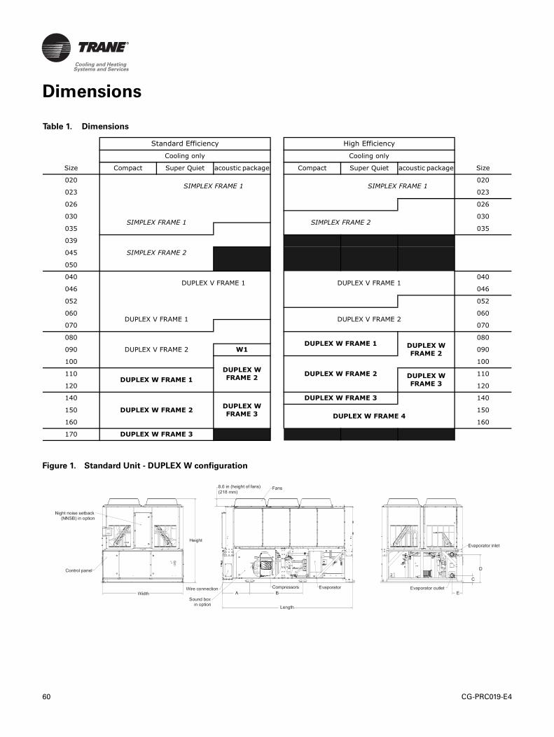
60 CG-PRC019-E4
Dimensions
Table 1. Dimensions
Standard Efficiency High Efficiency
Cooling only Cooling only
Size Compact Super Quiet acoustic package Compact Super Quiet acoustic package Size
020SIMPLEX FRAME 1 SIMPLEX FRAME 1
020
023 023
026 026
030SIMPLEX FRAME 1 SIMPLEX FRAME 2
030
035 035
039
SIMPLEX FRAME 2045
050
040DUPLEX V FRAME 1 DUPLEX V FRAME 1
040
046 046
052 052
060DUPLEX V FRAME 1 DUPLEX V FRAME 2
060
070 070
080
DUPLEX V FRAME 2DUPLEX W FRAME 1 DUPLEX W
FRAME 2
080
090 W1 090
100
DUPLEX W
FRAME 2DUPLEX W FRAME 2
100
110DUPLEX W FRAME 1
DUPLEX W
FRAME 3
110
120 120
140
DUPLEX W FRAME 2DUPLEX W
FRAME 3
DUPLEX W FRAME 3 140
150DUPLEX W FRAME 4
150
160 160
170 DUPLEX W FRAME 3
Figure 1. Standard Unit - DUPLEX W configuration
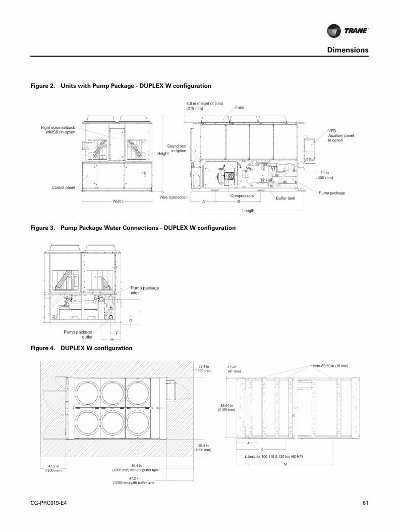
CG-PRC019-E4 61
Dimensions
Figure 2. Units with Pump Package - DUPLEX W configuration
Figure 3. Pump Package Water Connections - DUPLEX W configuration
Figure 4. DUPLEX W configuration
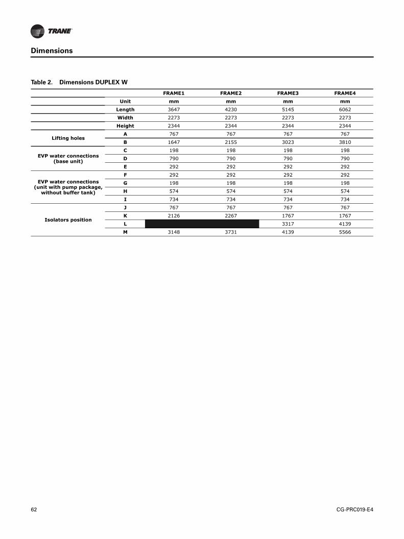
62 CG-PRC019-E4
Dimensions
Table 2. Dimensions DUPLEX W
FRAME1 FRAME2 FRAME3 FRAME4
Unit mm mm mm mm
Length 3647 4230 5145 6062
Width 2273 2273 2273 2273
Height 2344 2344 2344 2344
Lifting holesA 767 767 767 767
B 1647 2155 3023 3810
EVP water connections (base unit)
C 198 198 198 198
D 790 790 790 790
E 292 292 292 292
EVP water connections (unit with pump package, without buffer tank)
F 292 292 292 292
G 198 198 198 198
H 574 574 574 574
I 734 734 734 734
Isolators position
J 767 767 767 767
K 2126 2267 1767 1767
L 3317 4139
M 3148 3731 4139 5566
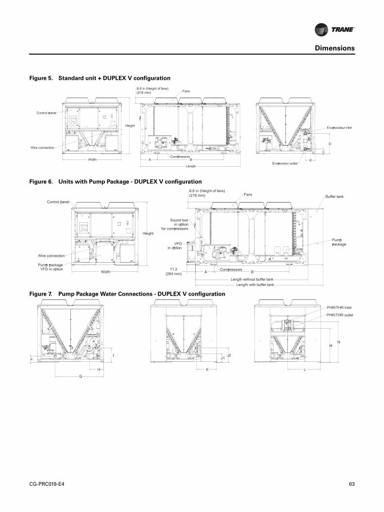
CG-PRC019-E4 63
Dimensions
Figure 5. Standard unit + DUPLEX V configuration
Figure 6. Units with Pump Package - DUPLEX V configuration
Figure 7. Pump Package Water Connections - DUPLEX V configuration
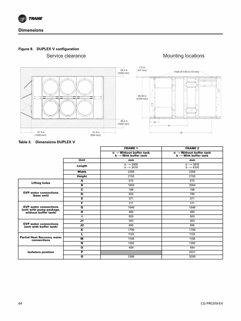
64 CG-PRC019-E4
Dimensions
Figure 8. DUPLEX V configuration
Table 3. Dimensions DUPLEX V
FRAME 1 FRAME 2
α → Without buffer tankb → With buffer tank
α → Without buffer tankb → With buffer tank
Unit mm mm
Lengthα → 2905b → 3416
α → 3819b → 4330
Width 2266 2266
Height 2150 2150
Lifting holesA 615 615
B 1650 2564
EVP water connections (base unit)
C 198 198
D 655 790
E 371 371
EVP water connections (unit with pump package,
without buffer tank)
F 211 211
G 1646 1646
H 480 480
I 500 500
EVP water connections(unit with buffer tank)
J1 303 303
J2 695 695
K 1796 1796
Partial Heat Recovery water connections
L 1125 1125
M 1158 1158
N 1392 1392
Isolators position
O 494 494
P 2027
Q 2388 3299
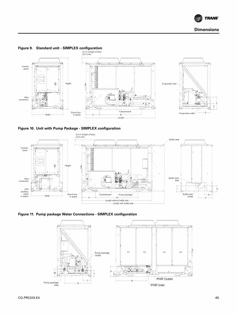
CG-PRC019-E4 65
Dimensions
Figure 9. Standard unit - SIMPLEX configuration
Figure 10. Unit with Pump Package - SIMPLEX configuration
Figure 11. Pump package Water Connections - SIMPLEX configuration
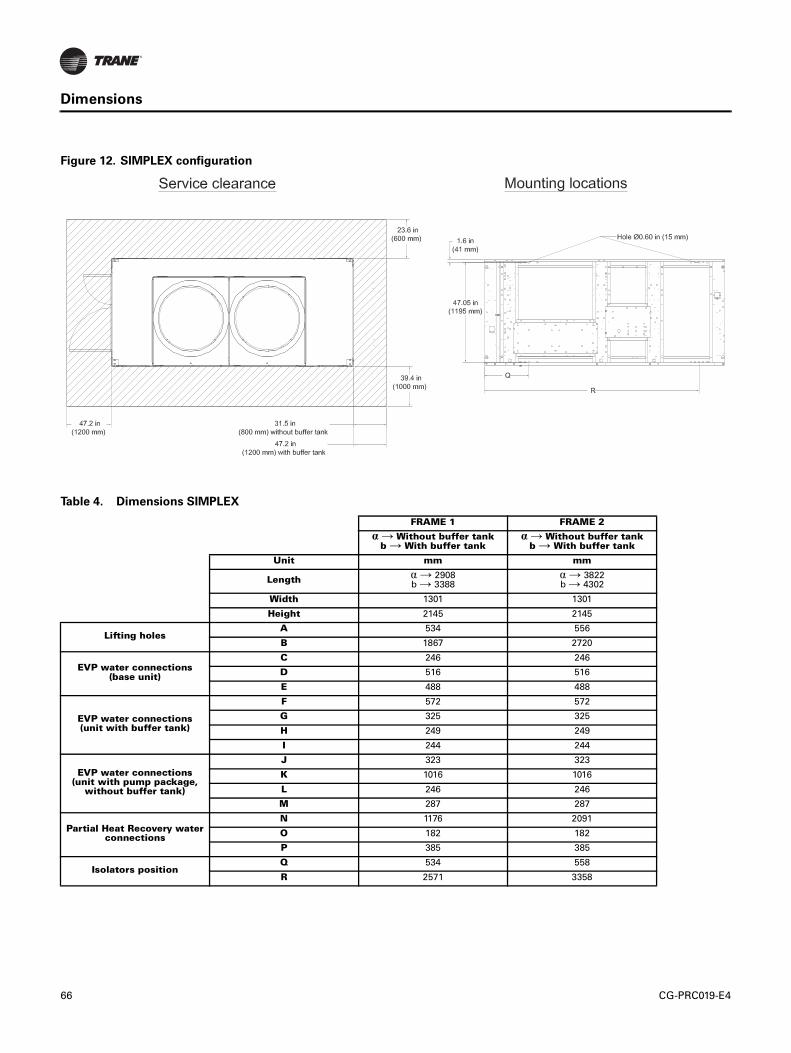
66 CG-PRC019-E4
Dimensions
Figure 12. SIMPLEX configuration
Table 4. Dimensions SIMPLEX
FRAME 1 FRAME 2
α → Without buffer tankb → With buffer tank
α → Without buffer tankb → With buffer tank
Unit mm mm
Lengthα → 2908b → 3388
α → 3822b → 4302
Width 1301 1301
Height 2145 2145
Lifting holesA 534 556
B 1867 2720
EVP water connections(base unit)
C 246 246
D 516 516
E 488 488
EVP water connections (unit with buffer tank)
F 572 572
G 325 325
H 249 249
I 244 244
EVP water connections(unit with pump package,
without buffer tank)
J 323 323
K 1016 1016
L 246 246
M 287 287
Partial Heat Recovery water connections
N 1176 2091
O 182 182
P 385 385
Isolators positionQ 534 558
R 2571 3358
CG-PRC019-E4 66
Mechanical Specifications
General
Units are constructed of galvanized steel frame with galvanized steel panels. Component surfaces
are finished with a powder-coated paint. Each unit ships with full operating charges of refrigerant
and oil.
Compressor and Motor
The unit is equipped with two or more hermetic, direct-drive, 3000 rpm 50 Hz suction gas-cooled
scroll compressors. The simple design has only three major moving parts and a completely
enclosed compression chamber which leads to increased efficiency. Overload protection is internal
to the compressors. The compressor includes: centrifugal oil pump, oil level sight glass and oil
charging valve. Each compressor will have compressor heaters installed and properly sized to
minimize the amount of liquid refrigerant present in the oil sump during off cycles.
Unit-Mounted Starter
The control panel is designed per IP-54. The starter is available in a solid-state soft starter or across-
the-line configuration, factory-mounted and fully pre-wired to the compressor motor and control
panel. A factory-installed, factory-wired 800 VA control power transformer provides all unit control
power (110 Vac secondary) and Trane CH530 module power (24 Vac secondary). Power line
connection type is standard with a fused disconnect switch.
Evaporator
Braze plate heat exchanger is made of stainless steel with copper as the braze material. It is
designed to withstand a refrigerant side working pressure of 45bars and a waterside working
pressure of 10bars. Evaporator is tested at 1.1 times maximum allowable refrigerant side working
pressure and 1.5 times maximum allowable water side working pressure. It has one water pass.
Blanket heaters protect the evaporator to an ambient of -18°C.
The evaporator is covered with factory-installed 19.05 mm Armaflex II or equal (k=0.28) insulation.
Foam insulation is used on the suction line. Water pipe extensions with insulation go from the
evaporator to the edge of the unit.
All evaporators are tested and stamped in accordance with PED.
CG-PRC019-E4 67
Mechanical Specifications
Condenser
Air-cooled coils have aluminum fins mechanically bonded to internally-finned copper tubing. The
condenser coil has an integral subcooling circuit. The maximum allowable working pressure of the
condenser is 45 bars. Condensers are factory proof and leak tested at 50 bars.
Direct-drive vertical discharge condenser fans are balanced. Three-phase condenser fan motors
with permanently lubricated ball bearings and external thermal overload protection are provided.
Cooling only units (CGAM) start and operate from 0°C to 46°C.
Refrigerant Circuit and Capacity Modulation
The simplex units have single refrigerant circuits. The duplex V and W units have dual refrigerant
circuits. Each refrigerant circuit has scroll compressors piped in parallel with a passive oil
management system. A passive oil management system maintains proper oil levels within
compressors and has no moving parts. Each refrigerant circuit includes filter drier and electronic
expansion valve.
Capacity modulation is achieved by turning compressors on and off.
Unit Controls (Trane CH530)
The microprocessor-based control panel is factory-installed and factory-tested. The control system
is powered by a pre-wired control power transformer, and will turn on and off compressors to meet
the load. Microprocessor-based chilled water reset based on return water is standard.
The Trane CH530 microprocessor automatically acts to prevent unit shutdown due to abnormal
operating conditions associated with low evaporator refrigerant temperature and high condensing
temperature. If an abnormal operating condition continues and the protective limit is reached, the
machine will shut down.
The panel includes machine protection for the following conditions:
• Low evaporator refrigerant temperature and pressure
• High condenser refrigerant pressure
• Critical sensor or detection circuit faults
• High compressor discharge temperature (with low temp evaporator)
• Lost communication between modules
• Electrical distribution fault: phase reversal
• External and local emergency stop
• Loss of evaporator water flow
68 CG-PRC019-E4
Mechanical Specifications
When a fault is detected, the control system conducts more than 100 diagnostic checks and displays
results. The display will identify the fault, indicate date, time, and operating mode at time of
occurrence, and provide type of reset required and a help message.
Clear Language Display Panel
Factory-mounted to the control panel door, the operator interface has an LCD touch-screen display
for operator input and information output. This interface provides access to the following
information: evaporator report, condenser report, compressor report, operator settings, service
settings, service tests, and diagnostics. All diagnostics and messages are displayed in “clear
language.”
Data contained in available reports includes:
• Water and air temperatures
• Refrigerant pressures and temperatures
• Flow switch status
• EXV position
• Compressor starts and run-time
All necessary settings and setpoints are programmed into the microprocessor-based controller via
the operator interface. The controller is capable of receiving signals simultaneously from a variety
of control sources, in any combination, and priority order of control sources can be programmed.
The control source with priority determines active setpoints via the signal it sends to the control
panel. Control sources may be:
• Local operator interface (standard)
• Hard-wired 4-20 mA or 2-10 Vdc signal from an external source (interface optional; control
source not supplied)
• Time of day scheduling (optional capability available from local operator interface)
• LonTalk LCI-C (interface optional; control source not supplied)
• BACNet (interface optional; control source not supplied)
• ModBus (interface optional; control source not supplied)
• Trane Tracer Summit system (interface optional; control source not supplied)
Quality Assurance
The quality management system applied by Trane has been subject to independent third-party
assessment and approval to ISO 9001. The products described in this catalog are designed,
manufactured and tested in accordance with the approved system requirements described in the
Trane Quality Manual.
CG-PRC019-E4 69
Options
Options
Application Options
High Ambient (CGAM)
Allows for ambient temperatures between 7°C and 52°C. Applies to HE version only.
Low Ambient (CGAM)
A variable speed drive on the first fan of each circuit allows for ambient temperatures between
-18°C and 46°C. Applies to SE version only.
Wide Ambient (CGAM)
A variable speed drive on the first fan of each circuit allows for ambient temperatures between -
18°Cand 52°C. Applied to HE version only.
Ice-Making with Hardwired Interface
Unit controls are factory set to handle ice-making for thermal storage application. This option
allows for full load operation of the chiller with leaving evaporator water temperature between -
7°Cand 18°C.
Low-Temperature Processing
An additional temperature sensor, at the compressor discharge, enables leaving evaporator
water temperature below 5.5°C.
Sound Options
Compact
This option includes 920 rpm fans.
Super Quiet Unit
This option includes low speed 700 rpm fans and compressor sound jackets.
Super Quiet with Night Noise Setback
This option will provide two speed fan motors. At night, on a contact closure all the fans run at low
speed bringing the overall sound level further down.
Comprehensive Acoustic Package
This option includes low speed 700 rpm fans and acoustical treatment for compressor.
70 CG-PRC019-E4
Options
Pump Options
Standard and High Head Pump Package
Pump package includes: one or standard or high head pumps, expansion vessels, drainage valves,
shut-off valves at entering and leaving connections, and service valves to isolate each pump for
repair/replacement.
The pump package is single point power integrated into the chiller unit power. The control of the
pump is integrated into the chiller controller. The CH530 displays evaporator pump starts and run-
times. Freeze protection down to an ambient of -18°C is included as standard. The cold parts of the
pump package will also be insulated.
Standard head pump is offered for applications that have short water loops or are de-coupled.
High head pump is offered for applications where the integrated chiller pump serves the entire
loop volume or where there is substantial vertical rise.
The dual pump option is designed with one redundant pump, it is controlled to operate both
pumps through a lead/lag and failure/recovery functionality. There is a variable flow option with
factory-installed bypass line.
Dual Contactors for Pump (field installed pumps)
Dual pump contacts to control two remote standard or high head pumps are included in the control
panel.
Single Contactor for Pump (field installed pumps)
Single pump contact to control a remote standard or high head pump is included in the control
panel.
Pump Flow Controlled by Mechanical Balancing Valve
A mechanical balancing valve is installed. This option replaced the outlet shut off valve.
Pump Flow Controlled by Variable Speed Drive
A variable speed drive is installed in an additional panel to control the pump. The inverter is
adjusted upon start up to balance the system flow and head requirements. The purpose is to save
on wasted pump energy caused by a traditional balancing valve.
CG-PRC019-E4 71
Options
Buffer Tank (only available with pump package)
The water tank is factory-installed for easy installation at the building site. The tank is engineered
for continuous flow and is fully insulated as standard and is designed with freeze protection down
to -18°C. The purpose of the tank is to increase the chilled water circuit inertia, which is necessary
with short water loops. A high circuit inertia reduces the compressor’s cycling to increase the
compressor life span and allow for more precise water temperature accuracy. It also saves energy
as compared to hot gas bypass.
Electrical Options:
Across-the-Line Starter/Direct on Line
Across-the-line starter is unit mounted with a IP-54 gasketed enclosure.
Across-the-Line Starter/Power Factor Correction
Across-the-line starter is unit mounted with a IP-54 gasketed enclosure. Power factor correction
capacitors are factory-installed to correct power factor to 0.95 at all loads.
Solid-State Soft Starter
This option unit mounted starter has a IP-54 gasketed enclosure. To extend starter life contactors
bypass current from the silicon control rectifies (SCRs) after startup.
Solid-State Soft Starter/Power Factor Correction
This option unit mounted starter has a IP-54 gasketed enclosure. To extend starter life contactors
bypass current from the silicon control rectifies (SCRs) after startup. Power factor correction
capacitors are factory-installed to correct power factor to 0.95 at all loads.
Disconnect Switch
A non-fused molded case disconnect switch, factory pre-wired with terminal power and equipped
with a lockable external operator handle, is available to disconnect the chiller from main power.
72 CG-PRC019-E4
Options
Control Options:
BACNet Interface
Allows user to easily interface via a single twisted-pair wiring to a factory-installed and tested
communication board.
LonTalk/Tracer Summit Interface
LonTalk (LCI-C) or Tracer Summit communications capabilities are available with communication
link via single twisted-pair wiring to factory-installed and tested communication board. This option
will support the functionality required to obtain Lon Mark certification.
LonTalk LCI-C Interface with Modbus Interface
Allows user to easily interface with Modbus through LonTalk via a single twisted-pair wiring to
factory-installed and tested communication board.
Time of Day Scheduling
Time of day scheduling capabilities are available for scheduling single chiller applications through
Trane CH530 panel (without the need for building automation system - BAS). This feature allows
the user to set up to ten events in a seven day time period.
External Chilled Water and Demand Limit Setpoint
Controls, sensors, and safeties allow reset of chilled water temperature, based on temperature
signal, during periods of low outdoor air temperature (chilled water reset based on return chilled
water temperature is standard). The demand limit setpoint is communicated to a factory-installed
and tested communication board through a 2-10 Vdc or 4-20 mA signal.
Auxiliary setpoint
Freeze protection provided by pump activation and heaters on all cold parts.
Freeze Protection - CH530 Control
Freeze protection provided via the CH530 control interface turns the water pump on based on
ambient temperature. The freeze protection is integrated into the main power of the unit. This
allows for a single electrical connection when installing.
Percent Capacity
Output the number of compressors that are operating as an analog 2-10 Vdc or 4-20 mA signal.
Programmable Relays
Predefined, factory-installed, programmable relays allow the operation to select four relay outputs.
Available outputs are: Alarm-Latching, Alarm-Auto Reset, General Alarm, Warning, Chiller Limit
Mode, Compressor Running, and Tracer Control.
CG-PRC019-E4 73
Options
Other Options
Access Guards
A coated wire mesh that covers the accesss area under the condenser coils.
Access Guards and Half Louvers
Available on larger W coil units a coated wire mesh covers the access area under the condenser
coils and half louvers cover the condenser coil.
Architectural Louvered Panels
Louvered panels cover the complete condensing coil and service area beneath the condenser.
Half Louvers
Louvered panels cover the condenser coil only. Available on the W coil units only.
Non-Lanced Aluminum Fins
Aluminum fins without slits help to prevent sand clogging the slit portion of a standard fin.
Non-Lanced Aluminum Fins with Pre-Coat Black Epoxy
This option uses pre-coated black epoxy non-slit aluminum fin stock for corrosion protection.
Non-Lanced Aluminum Fins with Pre-Coat Blue Fin
This option uses pre-coated non-slit aluminum fin stock to limit coil freezing and then defrost cycle.
Neoprene Pads
Neoprene isolator pads specially dimensioned to reduce vibration transmission to the
supporting structure when the unit is installed. Pads ship in the control panel.
Isolators
Molded elastomeric isolators sized to reduce vibration transmission to the supporting structure
when the unit is installed. Isolators ship with the chiller.
Flange Adapter
Kit to convert both water connections from grooved pipe to flanged connections. This includes:
grooved couplings and grooved to flange adapters.
Water Strainer
Factory-installed 1.6 mm water strainer is provided.
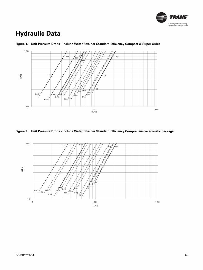
CG-PRC019-E4 74
Hydraulic Data
Figure 1. Unit Pressure Drops - include Water Strainer Standard Efficiency Compact & Super Quiet
Figure 2. Unit Pressure Drops - include Water Strainer Standard Efficiency Comprehensive acoustic package
1
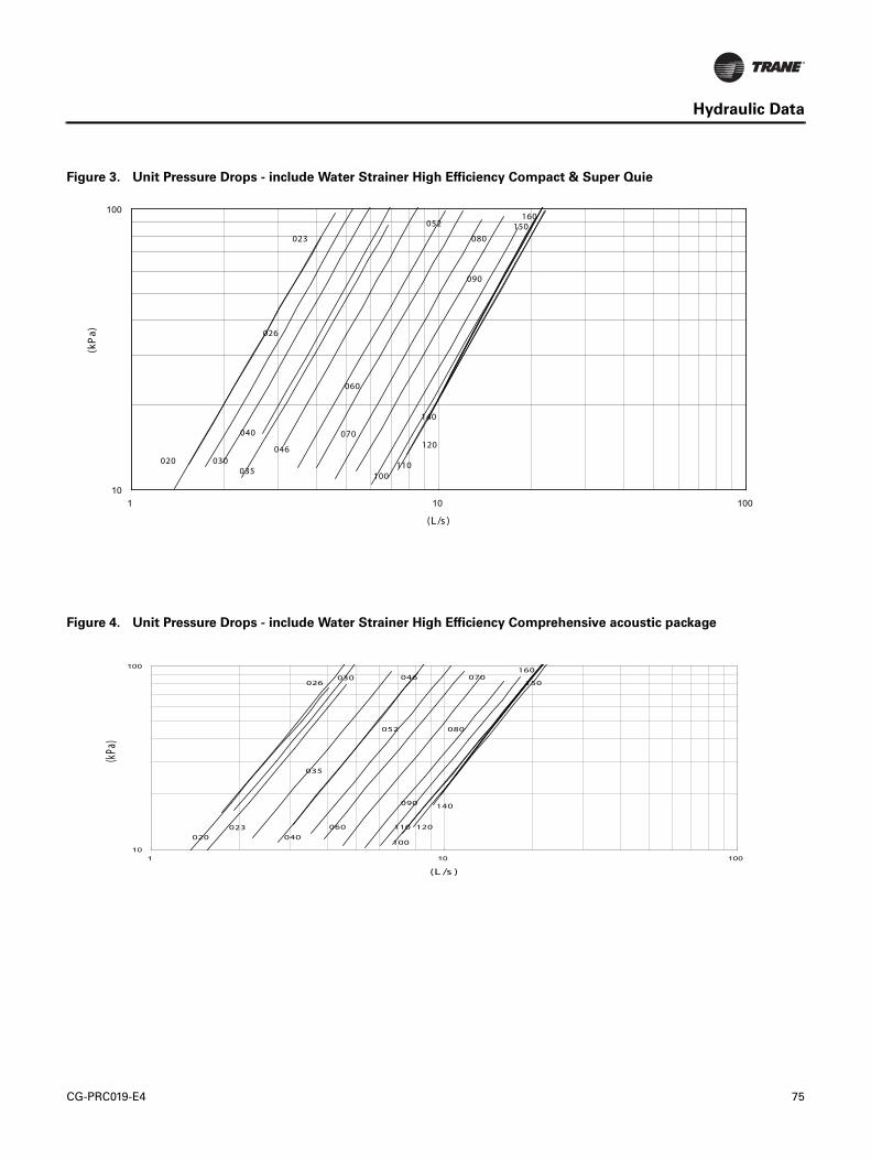
CG-PRC019-E4 75
Hydraulic Data
Figure 3. Unit Pressure Drops - include Water Strainer High Efficiency Compact & Super Quie
Figure 4. Unit Pressure Drops - include Water Strainer High Efficiency Comprehensive acoustic package
046
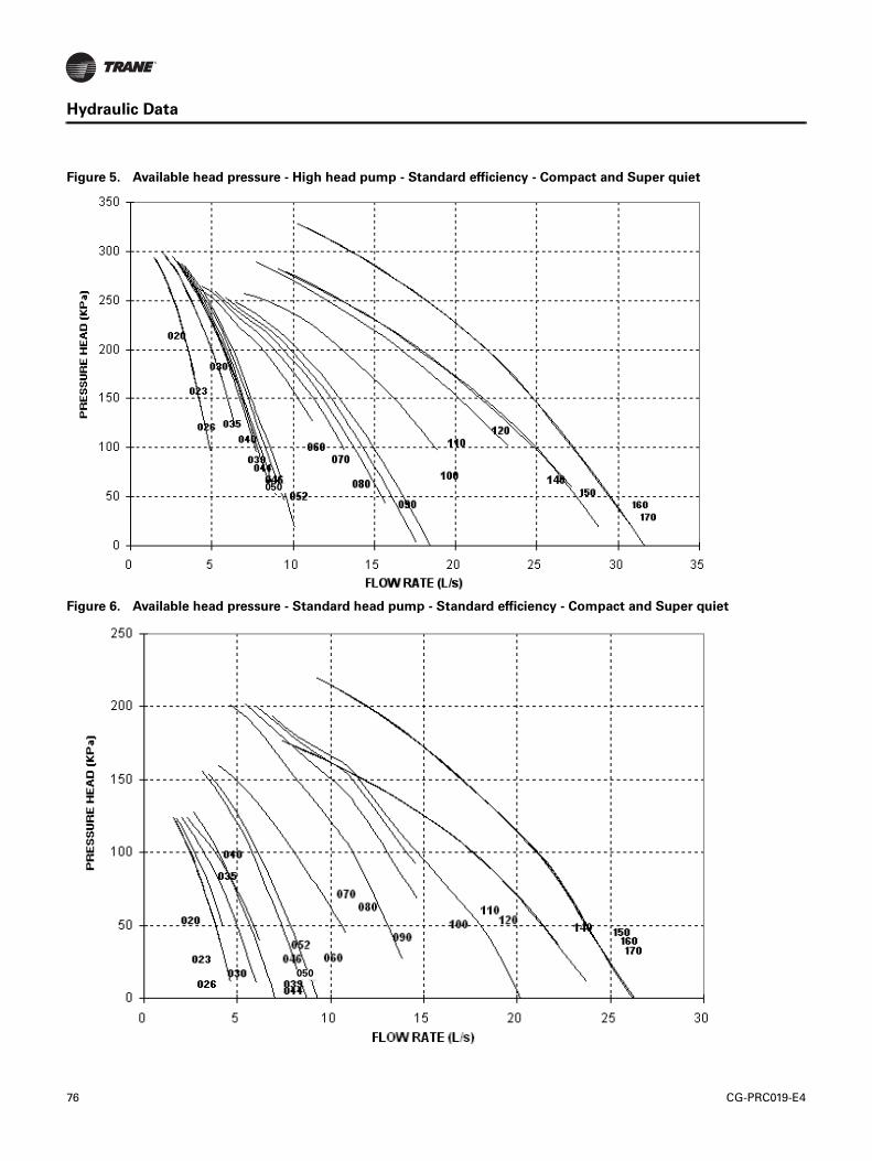
76 CG-PRC019-E4
Hydraulic Data
Figure 5. Available head pressure - High head pump - Standard efficiency - Compact and Super quiet
Figure 6. Available head pressure - Standard head pump - Standard efficiency - Compact and Super quiet
050
050
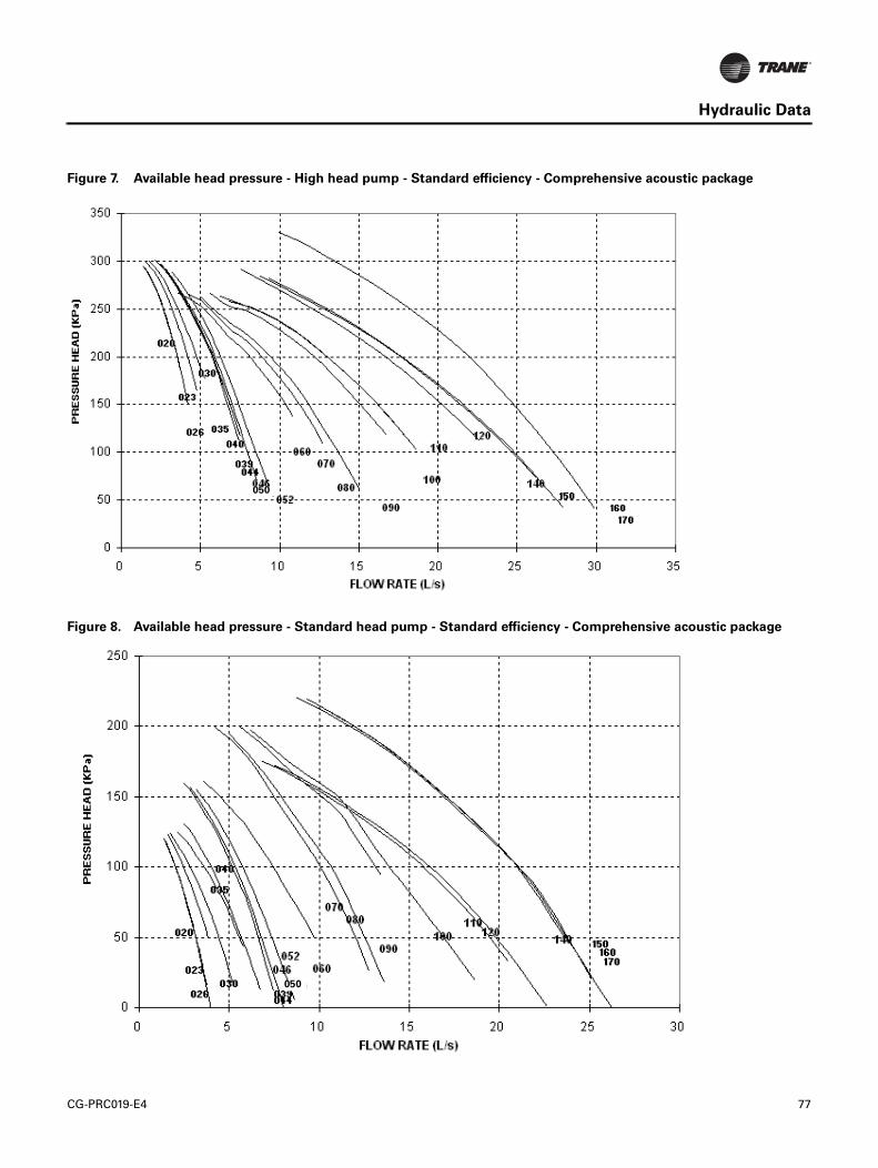
CG-PRC019-E4 77
Hydraulic Data
Figure 7. Available head pressure - High head pump - Standard efficiency - Comprehensive acoustic package
Figure 8. Available head pressure - Standard head pump - Standard efficiency - Comprehensive acoustic package
050
050
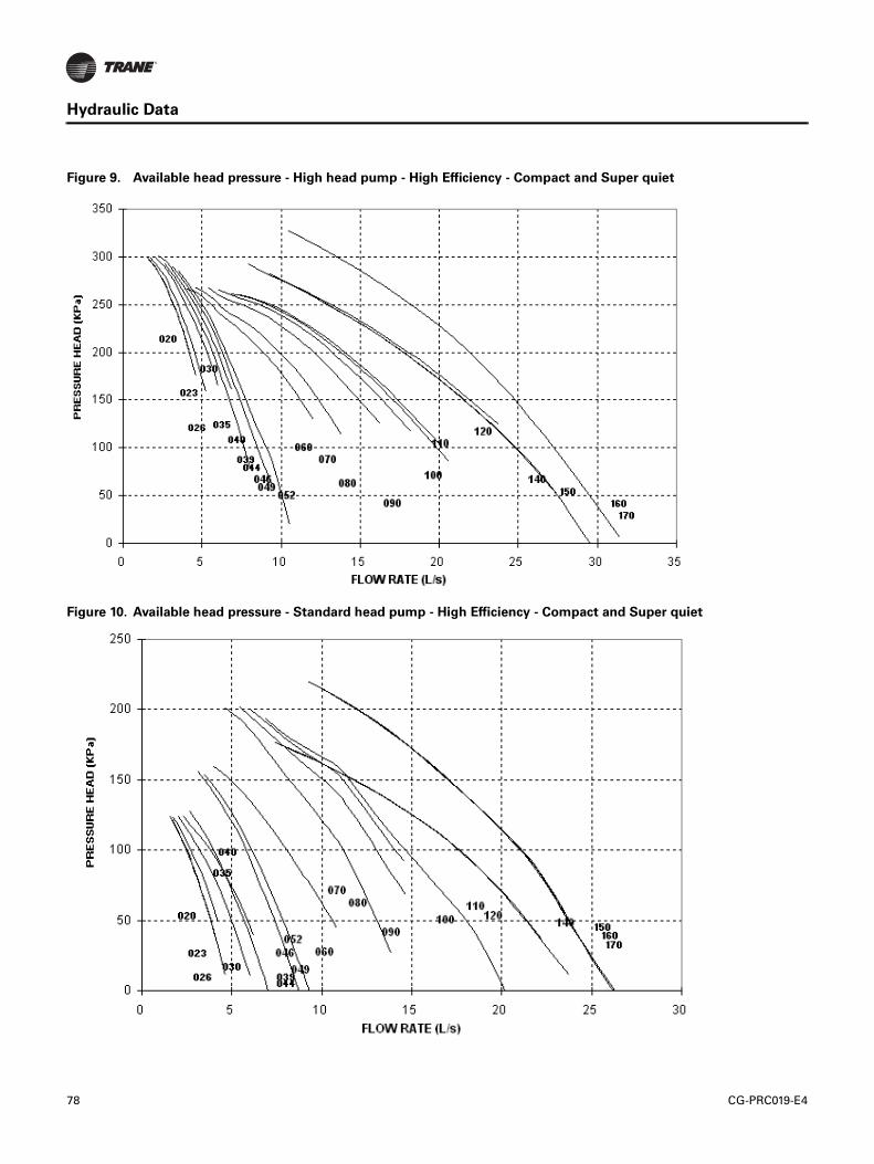
78 CG-PRC019-E4
Hydraulic Data
Figure 9. Available head pressure - High head pump - High Efficiency - Compact and Super quiet
Figure 10. Available head pressure - Standard head pump - High Efficiency - Compact and Super quiet
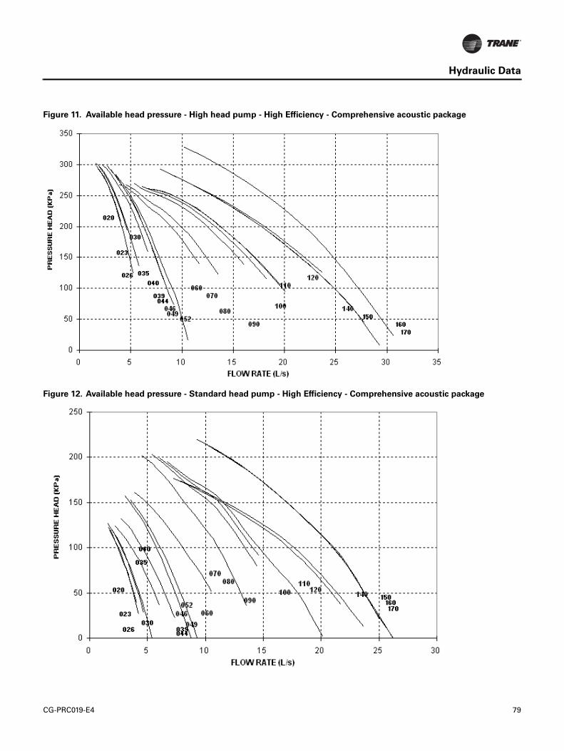
CG-PRC019-E4 79
Hydraulic Data
Figure 11. Available head pressure - High head pump - High Efficiency - Comprehensive acoustic package
Figure 12. Available head pressure - Standard head pump - High Efficiency - Comprehensive acoustic package
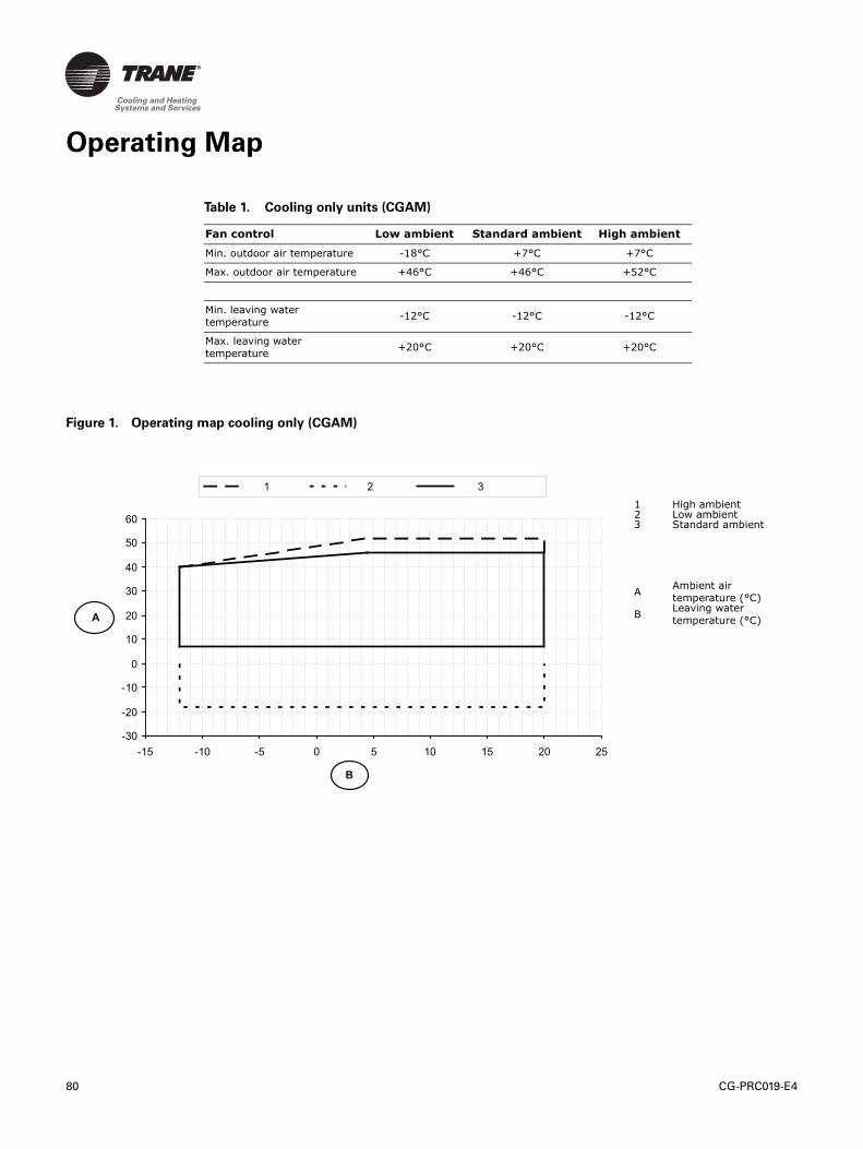
80 CG-PRC019-E4
Operating Map
Table 1. Cooling only units (CGAM)
Fan control Low ambient Standard ambient High ambient
Min. outdoor air temperature -18°C +7°C +7°C
Max. outdoor air temperature +46°C +46°C +52°C
Min. leaving water
temperature-12°C -12°C -12°C
Max. leaving water
temperature+20°C +20°C +20°C
Figure 1. Operating map cooling only (CGAM)
1 High ambient2 Low ambient3 Standard ambient
AAmbient air
temperature (°C)
BLeaving water
temperature (°C)
-30
-20
-10
0
10
20
30
40
50
60
-15 -10 -5 0 5 10 15 20 25
B
1 2 3
A
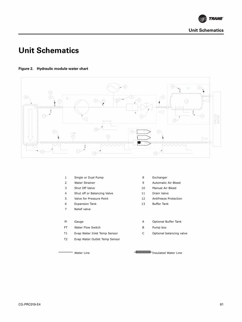
CG-PRC019-E4 81
Unit Schematics
Unit Schematics
Figure 2. Hydraulic module water chart
1 Single or Dual Pump 8 Exchanger
2 Water Strainer 9 Automatic Air Bleed
3 Shut Off Valve 10 Manual Air Bleed
4 Shut off or Balancing Valve 11 Drain Valve
5 Valve for Pressure Point 12 Antifreeze Protection
6 Expansion Tank 13 Buffer Tank
7 Relief valve
Pi Gauge A Optional Buffer Tank
FT Water Flow Switch B Pump box
T1 Evap Water Inlet Temp Sensor C Optional balancing valve
T2 Evap Water Outlet Temp Sensor
Water Line Insulated Water Line
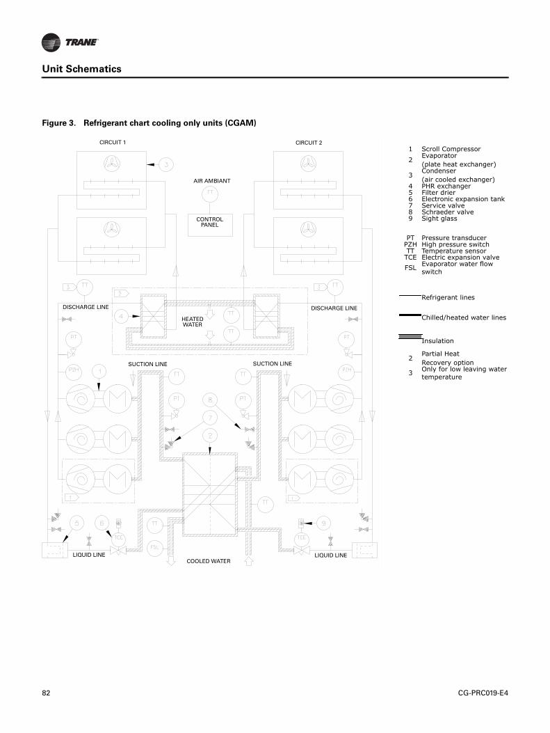
82 CG-PRC019-E4
Unit Schematics
Figure 3. Refrigerant chart cooling only units (CGAM)
1 Scroll Compressor
2Evaporator
(plate heat exchanger)
3Condenser
(air cooled exchanger)4 PHR exchanger5 Filter drier6 Electronic expansion tank7 Service valve8 Schraeder valve9 Sight glass
PT Pressure transducerPZH High pressure switchTT Temperature sensorTCE Electric expansion valve
FSLEvaporator water flow
switch
Refrigerant lines
Chilled/heated water lines
Insulation
2Partial Heat
Recovery option
3Only for low leaving water
temperature
SUCTION LINE
DISCHARGE LINEDISCHARGE LINE
CONTROL PANEL
SUCTION LINE
AIR AMBIANT
HEATED WATER
LIQUID LINE LIQUID LINECOOLED WATER
CIRCUIT 1 CIRCUIT 2

www.trane.com
For more information, contact your local Trane office or e-mail us at [email protected]
Literature Order Number CG-PRC019-E4
Date 12/09
Supersedes CG-PRC019-E4_0309
Trane has a policy of continuous product and product data improvement and reserves the right to change design and specifications without notice.
Trane bvba Lenneke Marelaan 6 -1932 Sint-Stevens-Woluwe, BelgiumON 0888.048.262 - RPR BRUSSELS