product and maintenance manual scv metal...
TRANSCRIPT

Precision Drilling Machines Tapping Machines Multi Head Drills Tool Grinders
Machine Vices Special Production Equipment
Accessories Riveting Machines Pedestal Grinders Metal Cutting Saws
YOUR BROBO DISTRIBUTOR IS:
PRODUCT AND MAINTENANCE MANUAL
SCV METAL CUTTING SAWS MODEL No. SCV350 & SCV400
SCV350 on Integrated Stand
BROBO WALDOWN (AUST) PTY. LTD.
A.C.N. 098 264 316 A.B.N. 42 098 264 316
65-67 Williams Rd, Dandenong, 3175 PO BOX 4274 Dandenong Sth, 3164 Victoria, AUSTRALIA. Tel: 61 3 9794 8751 Email: [email protected] Fax: 61 3 9794 8792 Website: www.brobo.com.au
Cer
tifi
ed S
yste
m
Quality ISO 9001

OPERATING MANUAL FOR BROBO GROUP SCV METAL CUTTING SAW TECHNICAL SPECIFICATION i CHAPTER 1: Installation of the Machine
1.1 Unpacking and Handling the Machine 1 1.2 Parts Checklist 2 1.3 Minimum Requirements 2 1.4 Anchoring the Saw 3 1.5 Connection to Compressed Air Supply 4
1.6 Connection to Power Source 4 CHAPTER 2: Safety and Accident Prevention
2.1 Operation of the Machine 6 2.1.1 Noise Level 6 2.1.2 Power Supply 7 2.1.3 Compressed Air Supply 7 2.2 General Requirements 7 2.3 Advice for the Operator 8 2.4 Machine Safety Devices 9 2.4.1 Reference Standards 9
CHAPTER 3: Main Functions and Operation of the Machine 3.1.1 Cutting Head 11 3.1.2 Saw Safety Guard 11 3.1.3 Vice Clamps 12 3.1.4 Saw 12 3.2 Preparation for Operation 12 3.3 Operation Recommendations 13
CHAPTER 4: Drawings, Layouts, Assembly and Spare Parts
4.1.1 Assembly Drawing (1 of 3) 14 4.1.2 Assembly Drawing (2 of 3) 16 4.1.3 Assembly Drawing (3 of 3) 17
4.2.1 Electrical Circuit 1PH/ 3PH & 3PH Dual Speed Circuit Diagram 18 4.2.2 Electrical Circuit 3PH with Dead Man Trigger (DMT) 19 4.3 Component Layout & Electrical Schematic Drawings (3PH) 20
4.4 Standard Saw Gearbox Assembly 21 CHAPTER 5: Adjustments for the Saw Unit
5.1 Changing the Blade 22 5.2 Cutting and Feeding Speeds 23
CHAPTER 6: Maintenance and Selection of Consumables
6.1 Role of the Operator 24 6.2 Maintenance Requirements 24 6.3 General Maintenance of Functioning Components 24
CHAPTER 7: Troubleshoot
7.1 Troubleshooting For Blade and Cutting Problems 26 7.2 General Troubleshooting 28
APPENDIX i. Hazard/Risk Assessment 30
ii. Warranty 31

TECHNICAL SPECIFICATION
STANDARD BLADE SIZES
Outer Diameter (� mm) Thickness (mm) Bore Size (mm) Number of Teeth
250 2.0 32 140 300 2.5 40 160 350 2.5 40 180 400 3.0 40 200
TABLE 1. Standard Blade Sizes ( - Recommendation) BLADE SELECTION CHART
Blade Diameter (� mm) and Number of Teeth
Material Outer Diameter (� mm)
Wall Thickness (mm) 300 315 350 400
1 300 320 350 400
2 240 240 280 340 20 3 180 180 220 240
1 300 320 250 400
2 220 220 260 280
3 160 160 180 200 40
4 140 140 160 180
1 300 320 350 400
2 220 220 280 300
3 160 180 200 220
4 140 160 180 200
50
5 120 140 160 180
1 280 300 320 360
2 200 200 220 240
3 180 200 200 220
4 160 160 180 180
80
5 140 140 160 180
1 300 300 340
2 220 200 220
3 200 180 180
4 160 140 160
100
5
140 120 140
1 300 340
2 200 220
3 180 180
4 160 160
HOLLOW CROSS-SECTION
120
5
120 140
10 280 280 280 300
20 160 160 200 240
30 140 140 160 200
40 120 120 140 140
50 80 80 100 120
SOLID SECTIONS
60
80 100 TABLE 2. Blade Selection Chart
NOTE - CHART GUIDE ONLY
This chart is issued as a guide only. Many other factors would attribute to the cutting performance of both the saw blade and the sawing machine. BROBO GROUP Pty. Ltd. will not accept any responsibility for the blade selection and/or machine breakages or unsatisfactory cutting performance of both the blade and/or the machine as a direct result of the selection.
!
i

Blade Type: AISI M-Z High Speed Steel (62-64 HRC, Hollow Ground)
Blue-oxide coated for:
Greater durability, Better coolant conveyance to the cutting edge, Reduces galling or "pick-up" on sides of the blade, Reduces brittleness of the steel.
Tooth Form: Bevelled on alternate sides - up to 180 teeth, or High-rolling, low-finishing teeth, "triple-chip" - above 180 teeth Drive Pin Holes (Qty � PCD): (S400 Series) 2 10.5mm 64mm Worm Gear Drive Ratio (S315/S350/S400): 1:33 Reduction Sound Level (dBA): 85 - 90 dB(A) Maximum MOTOR SPECIFICATIONS
Motor Type (Hz) Phase Voltage (V) RPM Kilowatt (kW)
50Hz Power Supply 1 240 1400 1.7
50Hz Power Supply 3 415 1400 / 2800 1.5 / 2.2
50Hz Power Supply 3 415 700 / 1400 1.1 / 1.5
60Hz Power Supply 1 230 1700 1.7
60Hz Power Supply 3 220 850 / 1700 1.1 / 1.5
60Hz Power Supply 3 440 850 / 1700 1.5 / 2.2
60Hz Power Supply 3 220 1700 / 3400 1.1 / 1.5
TABLE 3. Motor Specifications BLADE SPINDLE RPM
BLADE SPEEDS Motor Type
SCV350 SCV400
Frequency (Hz) RPM m/min RPM m/min RPM m/min 21 23 21 23 21 23
42 47 42 47 42 47 50
85 93 85 93 85 93
RPM ft/min RPM ft/min 26 93 26 93 26 93
52 186 52 186 52 186 60 (USA)
103 370 103 370 103 370
TABLE 4. Blade Spindle RPM
ii

CUTTING RANGE
Cutting Range (mm) Cross Sectional
Profile Angle
S315 S350 S400
90° 90 3 1/2” 115 4 1/2” 130 5 1/8” 45° 85 3 3/8” 110 4 5/16” 120 4 11/16”
90° 80 80 3 1/8” 3 1/8” 100 100 4” 4” 110 110 4 5/16” 4 5/16”
45° 75 75 3” 3” 85 85 3 3/8” 3 3/8” 95 95 3 3/4” 3 3/4”
90° 75 100 3” 4” 85 135 3 3/8” 5 5/16” 100 135 4” 5 5/16”
45° 80 65 3 1/8” 2 1/2” 75 95 3” 3 3/4” 100 95 4” 3 3/4”
90° 50
STD 2”
AUTO 3”
60 STD
2 3/4” AUTO 3 1/2”
60 STD
2 3/4” AUTO 3 1/2”
Note: The above values are based on a full size blade. The capacities will reduce accordingly when a worn blade is resharpened.
DIMENSIONAL SPECIFICATIONS Base Dimensions (L W H): 560 530 1800 mm Table Working Height: 968 mm SAW WEIGHT
Un-Packed Weight (kg) Packed Weight (kg)
S315/S350/S400 Saw Unit 136kg (300lb.) 150kg (330lb.)
Coolant Tank Complete 17kg (42lb.) 17kg (42lb.)
Sheet Metal Stand S315/S350/S400 28kg (62lb.) 28kg (62lb.)
Manual Vice Unit 25kg (55lb.) 25kg (55lb.)
TABLE 5. Cutting Range
TABLE 6. Saw Weight
iii

WARNING – HEAD HEAVY MACHINES
The metal sawing machines are heaviest where the saw heads are fitted and as such, care must be taken while relocating or moving the machines. !
CHAPTER 1 - Installation of the Machine 1.1 Unpacking and Handling the Machine Upon receiving the Brobo Group SCV Metal Cutting Saw, the machine should be standing upright and positioned centrally on top of a wooden pallet. While the machine is situated on the pallet, position the forklift arms under the pallet between the runners, keeping in mind that the machine is head heavy. Move the entire unit to an accessible area as close as possible to the final location. Carefully remove the wooden frame surrounding the saw unit (Figure 1). Once completed, proceed by elevating the machine away from the pallet base using a sling harness wrapped around the cutting head of the saw. Ensure that the floor is as level as possible before finally positioning the machine to the desired location. FIGURE 1. Handling of Metal Cutting Saw Unit
PLEASE OBSERVE AND FOLLOW THE INSTALLATION INTRUCTIONS ON PAGE 2
1
FORKLIFT ARMS

WARNING – OPERATING VOLTAGE VARIATION
Each saw model has an inbuilt safety system to protect it against voltage variations. However, for the machine to perform efficiently, ensure that the saw unit operates within ±10% limits of the recommended voltage of the motor.
!
1.2 Parts Checklist Along with the saw unit, check that the following accessories, packed "loose", are included as follows: A. STANDARD ACCESSORIES
i. 1 Saw Blade (as specified on page i)
ii. 1 Operating Handle
iii. 1 Service Kit (Hexagon wrenches 5”, 10” & 14”)
iv. 1 Operating Manual B. OPTIONAL ACCESSORIES
Part Number Description
9501120
9501180
Roller Conveyor Available in 1.5m or 3.0m lengths
Available with Plastic or Steel Rollers
75mm or 150mm Pitch
9301300 Fabricated Sheet Metal Stand
9301450 Angle Iron Stand
9301400 Trigger ‘Deadman” Switch
93018800 Brobolube Lubricants
- Additional Blade(s) - Custom to Client Requirements 1.3 Minimum Requirements For the machine to function correctly, the room in which the saw unit is to be installed must be in the vicinity of, and satisfy the following conditions: 415/240V Power Supply Working Pressure - Not less than 600kPa (6 Bar) and no greater than 900kPa (9 Bar)
Ambient Temperature - From -10°C to +50°C. Relative Humidity: Not more than 90%. Lighting: More than 500 LUX.
2
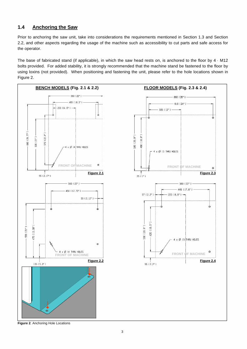
1.4 Anchoring the Saw Prior to anchoring the saw unit, take into considerations the requirements mentioned in Section 1.3 and Section 2.2, and other aspects regarding the usage of the machine such as accessibility to cut parts and safe access for the operator.
The base of fabricated stand (if applicable), in which the saw head rests on, is anchored to the floor by 4 M12 bolts provided. For added stability, it is strongly recommended that the machine stand be fastened to the floor by using loxins (not provided). When positioning and fastening the unit, please refer to the hole locations shown in Figure 2. Figure 2. Anchoring Hole Locations
FRONT OF MACHINE FRONT OF MACHINE
FRONT OF MACHINE FRONT OF MACHINE
BENCH MODELS (Fig. 2.1 & 2.2) FLOOR MODELS (Fig. 2.3 & 2.4)
Figure 2.1 Figure 2.3
Figure 2.2 Figure 2.4
3

1.5 Connection to Compressed Air Supply To ensure the ideal operation and long service life, it is recommended that the saw is connected to a compressed air system with similar characteristics shown in Figure 3 below.
Figure 3. Ideal Air Supply Connection 1.6 Connection to Power Source Before connecting the machine to the power supply, check that the socket is not connected in series with other machines. This condition is critical for the ideal operation of the saw unit. (Refer to Figure 4 for wiring of “4-CORE” power supply cable from the machine to a power plug. Note that single-phase machines are supplied in Australia with 15-amp plug).
Figure 4. Connection for “4-CORE” Wire System with Neutral Single and Three Phase
i. Single phase machines are provided with three pins, 15 amps rated plugs and leads for connection to 240V, 50Hz power supply in Australia.
ii. Three phase machines should be fitted with a suitable, approved four pin plugs (ie. three phase and
earthing - not provided)
iii. Check the power supplied and motor specifications before plugging in the machine. Check terminal connection on dual voltage motor terminal box and connect it accordingly to the corresponding voltage supply.
iv. If dual motor is requested, the motor is always connected to the higher voltage, unless otherwise
specified prior to order being placed.
4

VOLTAGE MAIN VOLTAGE 415/240V 1/ 3 PH 240V
To connect the machine to the power supply, proceed as follows:
1) Insert the power plug into the socket, while ensuring that the mains voltage is compatible for which the saw unit is operating at.
2) Switch the saw on by rotating the control switch located
on the saw head assembly as shown in Figure 5 below. Figure 5. Main Control Switch
3) Check that the motor is operating in the correct direction, that is the blade is rotating downwards and into
the direction of the vice clamps. 4) Ensure that all electrical leads and cables (including supply leads) are maintained in a good condition and
away from sharp objects. All leads should be replaced if cut, sliced or damaged in any way. Brobo Group SCV Metal Cutting Saw is now ready for use. Chapter 3 provides a detailed description of the various features of the saw and its operating cycles.
5

CHAPTER 2 - Safety and Accident Prevention The Brobo Group SCV Metal Cutting Saw has been designed and manufactured in accordance to Australian Standards. It is HIGHLY RECOMMENDED that the instructions and warnings contained in this chapter be carefully followed for correct usage of the machine.
2.1 Operation of the Machine The Brobo Group SCV Metal Cutting Saw is specifically design to cut ferrous and non-ferrous metal cross sections with solid or thin-walled profiles. Other types of material and machining are not compatible for use with the specifications of the saw. This machine involves a high-speed blade rotation; therefore extreme caution is required when operating the device. The employer is responsible for instructing the personnel who, in turn, are obliged to inform the operator of any accident risks, safety devices, noise emission and accident prevention regulations provided for by national and international laws governing the use of the machine. The operator must be fully aware of the position and functions of all the machine’s controls. All those concerned must strictly adhere to ALL instructions, warnings and accident prevention standards in this manual. The following definitions are those provided for by the EEC DIRECTIVE ON MACHINERY No. 98/37/CE: Danger Zone - any zone in and/or around a machine in which the presence of a person constitutes a risk
for the safety and health of that person.
Person Exposed - any person finding him or herself, either completely or partly in a danger zone. Operator - the person or persons given the responsibility of installing, operating, adjusting, maintaining,
cleaning, repairing, and transporting the machine.
2.1.1 Noise Level The noise level of an idling metal saw, fitted with a 180-tooth blade (supplied as standard by Brobo Group) has been measured to be below 85 dBA. This complies with the Australian Occupational Health and Safety (Noise) Regulations 1992.
Please note that peak impulse noise levels will be experienced due to variables including blade characteristics, type, and condition. This will also vary accordingly depending on the size and type of sample being cut. Under these circumstances, management should make available to the operator(s) the appropriate hearing protection equipment as prescribed under the above stated act.
WARNING – UNAUTHORISED MODIFICATIONS/REPLACEMENTS/USE
The manufacturer declines any responsibility whatsoever, either civil of criminal, in the case of unauthorised interference or replacement of one or more parts or assemblies on the machine, or if accessories, tools and consumable materials used are different from those recommended by the manufacturer, or if the machine is inserted in a plant system and its proper function is altered.
!
6

2.1.2 Power Supply The 415/240V power supply requirements for this machine are of a high level and unauthorised interference and or inadequate maintenance could result in a situation that could put the operator at risk. A qualified electrical engineer should always be assigned to maintain and repair the system. 2.1.3 Compressed Air Supply
Various functions of the saw are carried out via the use of 6kPa compressed air. During these operations, situations would arise where machine parts and materials are clamped together and would potentially pose a serious safety issue to an inexperienced operator. Operators should be thoroughly instructed about these hazards. Only a qualified electrician should carry out regular maintenance of this system.
2.2 General Requirements Lighting Insufficient lighting during the operation of the saw unit would constitute a safety hazard for the people concerned. For this reason, the user of the machine must provide adequate lighting in the working area to eliminate areas in shadow, whilst also preventing dazzling illumination sources (reference standard ISO 8995 - 2002 ‘Lighting of Indoor Workplaces’). Connection Check that the power supply cables, compressed air supply (if applicable) and coolant system complies with, and are operating within the acceptable range of the saw capabilities. Faulty, damaged or worn components must be replaced immediately. Earthing Systems The installation of the earthing system must comply with the requirements stated in the IEC Standards Part 195: Earthing and Protection Against Electric Shocks 1998. Position of the Operator The user controlling the machine saw operations must be positioned as shown in the diagram below. Figure 6. Correct Position for Operating Saw Unit
7

2.3 Advice for the Operator
Protective eyewear or goggles must be worn at all times while attending and operating the metal saw.
Do not attempt to operate the machine unless all safety guards are in operation. The guard
must fully cover the blade when the head is in the uppermost position.
Ensure that hands and arms are kept clear of the cutting zone when the machine is operating.
Do not wear oversize clothing with long sleeves and oversize gloves, bracelets, necklaces or any other loose object that may become entangled in the machine’s blade during cutting. Long hair must be tied back or placed in a hair net.
Always disconnect the power supply to the machine before carrying out any maintenance work or adjustments. This includes cases of abnormal operations of the machine.
Any maintenance work performed on the hydraulic, pneumatic or coolant systems must be carried out only after the pressure in the system has been released.
The operator MUST NOT conduct any risky operations or those not required for the cutting in course (eg. remove swarf shavings from the machine while cutting). Never move the saw while the machine is operating.
Always keep the workplace are as clean as possible. Remove equipment, tools or any other objects from the cutting zone.
Support the work piece on both sides of the machine to prevent it falling or jamming during the cutting cycle.
Ensure that the specimen being cut is secured firmly in the vice clamps and the machine has been correctly set. Figure 7 show some examples on how to correctly clamp different specimen profiles. Before commencing the cut, be sure the vice(s) is securely clamped and the machine set-up is correct.
8

Figure 7. Correct Clamping of Cutting Specimens
Do not use cutting blades of different sizes to those recommended to the machine’s specifications. Always follow safe practices and inspection procedures when installing blades (Please refer to section 5.1 Changing the Blade). When cutting very small specimens, ensure that the workpiece is not dragged behind the back fence support, where it could get lodged behind the blade. If the blade jams during a cut, activate the emergency stop function immediately. Do not continue forcing the blade through. This could damage the blade, the specimen or be a cause for potential injury to the operator.
Always turn off the machine before carrying out any repair work. Consult the Brobo Group Engineering Department in the country in which the machine was initially purchased.
2.4 Machine Safety Devices This product and maintenance manual is not purely intended as a guide for the usage, operation and maintenance of the saw unit in a strictly production environment; it is instead an instrument to providing information on how to use the machine correctly and safely. The following standards listed in section 2.4.1, which are applicable to the Brobo Group SCV Metal Cutting Saw, are those specified by the EEC Committee that governs safety of machinery, health and safety at work, personal protection and safeguarding of the work environment. In addition, the saw also complies with the Australian Standards regarding the safeguarding and general requirements for electrical equipment. 2.4.1 Reference Standards MACHINE SAFETY EEC Directive No. 98/37/CE - Machines Directive EEC Directive No. 91/368 - 94/68 - Amends sections of EEC Directive No. 98/37/CE relating to machine
safety
9

EEC Directive No. 73/23 - Low Voltage Directive AS4024.1 - 1996 - Safeguarding of Machinery
HEALTH AND SAFETY AT WORK AS3100 - 2002 - General Requirements for Electrical Equipment OH. & S. 1995.81/1995 - Compliance References EEC Directive No. 80/1107; 83/477; 86/188; 88/188; 88/642 - Protection of workers against risks caused by
exposure to physical, chemical and biological agents in workplace EEC Directive No. 73/23 and Special EEC Directives No. 89/654; 89/655 - Improvements in health and
safety at work
10

CHAPTER 3 - Main Functions and Operation of the Machine
3.1.1 Cutting Head As the name suggests, the cutting head is the focal area where most of the specimen cutting takes place. Thus, correct saw blade selection such as size, number of teeth and tooth pitch are all critical factors that determines the overall performance and quality of the final cuts. In addition, the use of correct saw blade provides minimum burr to the workpiece while maximises the safety to the operator during each cutting procedure.
3.1.2 Saw Safety Guard
The primary purpose of the saw safety guard is to protect the user from the spinning blade. It also functions as a safety device to protect the operator from any broken tooth, swarf or high-velocity particles that might be dislodged by the cutting process.
3.1.3 Vice Clamp
As the main feature of this saw machine, the self centring vice (SCV) jaws adjust about a central datum line. This method of clamping design allows for three distinctive advantages:
i) Since both the back front and rear vice jaws move simultaneously, the jaws can accommodate and achieve a range of cuttings which is other restricted by a conventional cold saw with a fixed back fence. This is particularly evident when cutting materials of a complex profile and cross section.
ii) Due to the design of the vice clamps, the saw head and vice unit rotates independent of one another
which allows for a greater cut angle (-60° to +60°)
iii) As the vice jaws clamps both the part and the off-cut side, the off-cut is securely fasten to prevent it from retracting towards to the blade and possibly jamming the machine. Also, the clamping on both sides of the cut often reduces the likelihood of burrs forming on the parent material at the cutting cycle end.
Cutting Head
Saw Safety Guard
Vice Clamp
Fabricated Stand (Optional)
Gearbox
Motor
Pivot Locking
Handle
1
2
3
4
5
7
6
11

3.1.4 Saw Handle (with ‘Dead Man’ Trigger Switch) Although comes as a standard, the saw handle can be installed with a Dead Man’ type trigger switch enabled instant switching at the operators control. This particular configuration allows for increased efficiency and safety.
3.2 Preparation for Operation The following procedure is recommended for the correct cutting using the Brobo Group SCV Metal Cutting Saw. PROCEDURE
i) Using a non-flammable and toxic free solvent, clean the machine to remove any corrosion protective coating prior to use.
ii) Ensure that both the air and electric power systems are turned on, where applicable. The electrical power
source must be available before any pneumatic (if applicable) functions will operate.
iii) To adjust the angle of the cutting surface, loosen the pivot locking
handle as shown in Figure 9. Fine-tune the angle required and re-tighten the handle to secure the workbed.
iv) Place the cutting specimen you wish to cut into the vice clamps.
Manually adjust the clamps so that the jaws are clamped firmly to the workpiece.
v) Position the vice clamps and component as close to the blade as
possible without interfering with the travel of the blade or guard. Vice relocation is required whenever the head angle is altered.
vi) To initiate the cutting process, either turn the switch to 1 or 2 settings, or press the START buttons.
- Depress the Dead Man Trigger to initiate the blade intake. - Position blade to commence cutting through component and maintaining a constant forward feed cutting rate until the end of the stroke. - Return saw cutting head to the initial rest position.
vii) Machine is ready for the next cutting cycle.
WARNING - BLADE JAMMING
If the saw blade jams during a cut, engage the EMERGENCY STOP immediately. Remove the part, check that the blade is not damage and if need be, replace the blade.
!
Figure 9. Pivot Locking Handle
\
Figure 8. Saw Handle
WARNING – SAFETY GEAR
Protective clothing, safety glasses and gloves should always be worn while loading parts, operating the machine, or undertaking any maintenance work on the saw.
!
12

3.3 Operation Recommendations Select the correct saw blade with the correct tooth pitch and form to suit the material to be cut to provide
minimum burr and maximum blade lifespan. Use the smallest diameter blade and coarsest pitch that is practical within the required speed and material
limitations. Generally use a tooth pitch to give 2 - 4 teeth engagement with the material during cutting.
Ensure that sufficient coolant is flowing over the cutting teeth.
Do not allow the machine’s gearbox to run idle in the upright position for more than 3 minutes otherwise,
damage can occur to the drive system. The rate of feed affects the quality of the final cut and blade life. This varies also by the material and cross-
sectional dimensions. When cutting stainless steel or high carbon steel (Brinnel Hardness above 200), the slowest speed machine should be used together with a cobalt type high speed steel blade.
When manually feeding the saw head, keep in mind to maintain a steady, continuous pressure, thus
avoiding work hardening on the cutting piece. Avoid ‘forcing’ the blade through the material as this might damage or break the blade.
As a rule of thumb the softer the component, the faster the rate of speed. Thus, it is recommended that
slower speeds be used for hard and tough materials and higher speeds for soft, ductile materials. Note that for non-ferrous materials such as brass, copper, aluminium etc. require much faster speeds than provided on this machine. If these are the majority of materials cut, a Brobo NF Series machine should be considered.
13

CHAPTER 4 - Drawings, Layouts, Assembly and Spare Parts
4.1.1 Assembly Drawing (Sheet 1 of 3)
14

15

4.1.2 Assembly Drawing (Sheet 2 of 3)
14
16

4.1.3 Assembly Drawing (Sheet 3 of 3)
17

4.2.1 Electrical Circuit 1PH/ 3PH & 3PH Dual Speed Circuit Diagram
18

4.2.2 Electrical Circuit 3PH with Dead Man Trigger (DMT)
19

4.3 Component Layout & Electrical Schematic Drawings (3PH)
20

4.4 Standard Saw Gearbox Assembly
21

DANGER – ELECTROCUTION
Make certain that the power to the manual saw is turned off before proceeding with changing the saw blade.
CHAPTER 5 - Adjustments for the Saw Unit 5.1 Changing the Blade To replace a worn saw blade:
i) Disengage the linkage arm that is between the guard linkage system and pivot block (at the pivot block by
compressing the spring and moving the bolt through the slot).
ii) Slide the saw guard up as far as possible (as if it was opening during a cutting cycle) to gain access to the spindle nose.
iii) Loosen the spindle screws (LH thread), using the 14mm hexagonal wrench provided, and remove the
counter plate. To loosen the spindle screw, insert the wrench (short end) into the socket head cap screw and firmly knock the wrench with the palm of your hands until the screw is loosened. If this method fails to free the screw, place a piece of timber under the blade of the machine, and loosen (or tighten) the screw while holding the saw head of the machine down (blade against the timber).
iv) Remove the worn saw blade away from the spindle hub. Using a soft brush, clean the face of the spindle,
counter plate and mounting faces of the blade of any dirt or swarf that was trapped by the previous cutting cycles.
v) Place the old saw blade into the new blade packaging and disposed of it safely. Carefully mount the new
blade onto the spindle hub, ensuring that the blade is rotating into and towards the back fence, and replace the counter plate utilising the drive pins as guides as it passes through the pinholes on the blade.
vi) Rotate blade back against the drive pins in a counter-clockwise and finger tighten the spindle screw.
vii) Firmly retighten the spindle screws, ensuring that the saw blade spins uniformly and aligned parallel with
the safety guard.
viii) Lower the outer guards and make certain the pin of the linkage arm is re-engaged with the track on the inner guard and reconnect the guard linkage.
ix) The new blade is ready for use. To check that the blade is performing correctly, carry out a sample cut on
a piece of off-cut.
x) If optional devices are supplied, mount the stock support and rollers on either side of the clamping jaws. Normally stock should feed from left to right, but it can be feed from the right to left, if required.
24
22

5.2 Cutting and Feeding Speeds As previously highlights, the rate of feed largely affects the quality of the final cut. As such, the blade life is also dependent on the feed at which it is cutting the sample material - in particular, the type of material and also the cross sectional dimensions. Thus, to extend the life of the blade, maintain a firm and steady pressure whilst allowing the blade teeth to cut at an optimum rate. Do not force the blade through the material! This could cause numerous problems including breaking the blade teeth, jamming the blade with the cutting part or fracturing the blade spindle. The cutting action also generates a large amount of heat within the cutting sample due to frictional contact. Should this heat affect the material you are cutting in any way, the heat should be dissipated using the coolant system.
23

CHAPTER 6 – Maintenance and Selection of Consumables 6.1 Role of the Operator The person operating and maintaining the Brobo Group SCV Metal Cutting Saw must familiarise themselves with these instructions for their own safety and that of the others, in addition to safeguarding the production of the machine. Responsibility must be taken by the user on the general maintenance and up keeping of the unit as specified in this chapter, with particular emphasis on:
Check to ensure that other operators of the machine always aware of and comply with the relevant safety instructions and standards as specified in Chapter 2 - Safety and Accident Prevention. Therefore, check that the safety devices are operational and work perfectly and that personal safety requirements are complied with.
Ensure that the working cycle is efficient and guarantees maximum productivity, inspect the:
- Functions of the main components of the machine - Sharpness of the blade and coolant flow - Correct working parameters for the type of material being cut
Verify that the quality of the cut meets the requirements and that the final product is free from any
machining defects. 6.2 Maintenance Requirements
All maintenance must be carried out with the power switched off and the machine in emergency stop condition.
To guarantee for optimum operation, all spare parts must be Brobo Group originals.
On completion of maintenance works, ensure that the replaced parts or any tools used have been
removed from the machines before starting it up.
Any behaviour not in accordance with the instructions for using the machine specified in this manual may create hazards and/or safety risks for the operator.
Therefore, read and follow all the instructions for use and maintenance of the machine and those on the
product itself. 6.3 General Maintenance of Functioning Components The general maintenance operations that should be carried out regularly are as follows:
i) Keep the vice clamps, overall machine and path of the cutting blade free of any offcuts, accumulated swarf and coolant using compressed air or preferably thread-free cloth.
ii) Observe the oil level on the gearbox. The first oil change should be performed after the initial 25 hours of
operation and 300 hours of operation thereafter. Use extreme pressure industrial gear oil - ISO VG 220 viscosity, conforming to AGMA 5EP, US Steel 224 or API GL-2 specifications to which 3% colloidal molybdenum disulphide has been added. Refilling point is situated in the handle bar mounting threaded hole. The required quantity to refill is approximately 1 litre for the S315/S350/400 gearboxes. Gearbox oil is available from BROBO GROUP Pty. Ltd. in 2 Litre packs (Part No. 9501090).
24

iii) Change coolant as required, or whenever the coolant starts to get dirty or emits a stale odour. The coolant compensation tank should be checked regularly. Coolant level would expect to naturally decrease over time due to natural evaporation. Use premium quality coolants such as CoolTech 500 or SlideTech 68. Coolant is available from BROBO GROUP Pty. Ltd. in 2 litre packs (Part No. 9301570).
iv) Lubricate the saw head pivot shaft and rotary table regularly (after every 40 hours of operation, or
weekly) with an NLGI 2 extreme pressure grease, Shell Alvania No.1 grease or equivalent. v) Clean the vice and lubricate any moving joints or sliding surfaces with good quality oil.
vi) Clean the machine regularly and keep any unpainted surfaces lightly oiled to protect from rust and
corrosion. vii) The air supply for the pneumatic air vices should be checked regularly such that it is free of any
condensed water molecules and the filter should be drained frequently.
viii) Ensure that the machine performs cuts perpendicular to the work surface. If not, contact Brobo Group engineering department.
ix) Test that the blade is at right angles to the workpiece back fence. If not, contact Brobo Group engineering
department.
x) Check that the 0° notch on the fixed worktable is aligned with the gradation on the turntable. If not, adjust as described in Section 5.2.
xi) Examined that the precision of the 15°, 30°, 45° left and right stops are correct and accurate.
25

CHAPTER 7 - Troubleshoot 7.1 Troubleshooting For Blade and Cutting Problems
PROBLEM IDENTIFIED DIAGNOSIS SOLUTIONS
Cuts produced are not at 90° and/or are not perpendicular Frequent and/or excessive teeth breaking
Head speed too low or too high Blade with worn teeth Angularity of blade to workpiece back fence and vice clamps
Blade not perpendicular to work surface Broken teeth Incorrect lubricant/coolant fluid Material too hard Blade not worn in correctly
Reduce or increase head speed respectively. Replace with new blade, with reference to Section 5.1 Changing the Blade. Adjust the position of the blade so that it is at right angles to the
workpiece back fence using the 0° notch as reference; set the stops at
60° left and right. Adjust the blade using the appropriate screws such that it is perpendicular to the work surface. Check the hardness of the material being cut corresponds within the capabilities of the blade. Check the water and oil mixture; check that the holes and/or hose are not blocked; direct the nozzles correctly; check that the lubricant/coolant fluid conforms to those specified in Section 6.3 General Maintenance of Function Components. Check the cutting speed, feed speed, blade type and parameters are correct for the particular application. With a new blade, it is necessary to start cutting at half feeding speed. After a normalising period (cutting surface about 300cm2 for hard materials and 1000cm2 for softer materials), both cutting and feed speeds can be brought up to normal values.
26

Rapid teeth wear Broken blade
Blade with incorrect and/or excessive fine tooth pitch Workpiece not clamped firmly in place Excessive vibrations
Head speed too slow or too high Cutting pressure to high Insufficient coolant Non-homogenous material being cut Head speed to high Teeth in contact with material before commencing the cut Insufficient coolant Excessive vibrations
As excessive pressure is exerted of the incorrect teeth profile, replace the blade with correct tooth pitch dimensions and profile. Any movement of the workpiece during the cutting process can cause broken teeth; check the vice clamps, clamping jaws and clamping pressure is satisfactory. Specimen vibrates in the vice; check that the vice clamps are position correctly and the clamping pressure are adequate. The blade/slide runs over the material without cutting it; increase or decrease head speed respectively. Reduce cutting pressure Check the coolant level and clean piping and nozzles The material present may not be homogenous either on the surface, such as oxides or sand present, or in sections, such as under-cooled inclusions. The variances in grain development cause the premature wearing of teeth and consequently, break as the result. Homogenise or clean these materials. Reduce head speed Always check the position of the blade before starting a initiating a new cut or job Check the coolant level and clean piping and nozzles Specimen vibrates in the vice; check that the vice clamps are position correctly and the clamping pressures are adequate
27

7.2 General Troubleshooting Below lists of some of the most commonly identified problems associated with the Brobo Group SCV Metal Cutting Saw and the recommended troubleshooting procedures to undertake to rectify the situations. If the solutions provided do not resolve the problem, or the problem identified differs from those listed, immediately contact Brobo Group engineering department.
PROBLEM IDENTIFIED DIAGNOSIS SOLUTIONS
Spindle motor will not rotate
Vice clamps does not engage (pneumatic vice only)
Electrical power supply not connected
Loose contactors Motor burnt out Blown fuses
Power supply not switched on Air supply hose is not connected Emergency condition tripped
Ensure that the main power cable is plugged in and switched on. Check the phases, cables, plugs and sockets for loose connection. Also check that the motor connections are in place. Verify that the contactors are not loose. If contacts are short-circuited, contact Brobo Group engineering department immediately Check that it has not burnt out, that it turns freely and there is no moisture in the main electrical unit. The winding can be rewound or replaced Examine that the fuses are intact and fitted correctly, otherwise replace or tighten the fuse holders Ensure that the main power cable is plugged in and switched on. Check the phases, cables, plugs and sockets for loose connection. Also check that the motor connections are in place Inspect that the air supply cable is connected to the air fittings located at the back of the saw Check that the emergency stop button is released, specified in Section 3.1.4 Control Panels. Check the contacts and the cable connections
28

Machine open slowly or not at all Coolant system not operational
Air treatment unit obstructed Blocked pneumatic tubing Hydraulic oil level and pressure system Blocked coolant tubing
Check that the pneumatic input and inlet connections are not obstructed and that the supply hose is not blocked or kinked Check that it is not kinked, severed or blocked. Remove any blockages Check for any leaks present within the catchment unit. Top up the with coolant as recommended in Section 6.3 General Maintenance of Functioning Components Check that it is not kinked, severed or blocked. Flush out any blockages
29

APPENDIX - RISK/HAZARD ASSESSMENT
Hazard Type Hazard Identification Hazard Assessment
Hazard Management Strategies (Recommended for the Purchasing / Buyer / User)
Cutting/Severing Low/Med Keep machine correctly guarded and operational at
all times. Keep hands clear of rotating blade when cutting.
Entanglement Low Do not wear loose jewellery, clothing or items that
might get caught in the saw. Always keep the work area free of unnecessary
objects or tools.
Mechanical
Puncturing Low Wear protective gloves when handling and /or
changing the blades. Power source is to be isolated prior to opening
electrical enclosures.
Electrical Electrocution Low Remove the power supply when any maintenance
and/or repairs are to be undertaken. Power source is to be isolated prior to opening
electrical enclosures.
Thermal Burn Low Under normal working conditions the gearbox can
become hot thus, do not touch. Be careful when handling workpiece after cutting, as
it might be very hot.
Noise - Low
Under no load testing, the noise level measured is below 85 db (A).
If the noise level becomes too high during a cutting cycle, stop the process and inspect for problem, if any are present.
Substance - Low
Care must be taken as some coolants may be harmful or cause allergic reactions. Please read the labels carefully.
Keep the work area clean and regularly remove excess coolant, oils and other impurities.
Unexpected Start Up Low During a power failure, turn the machine off. If problem persists, please contact Brobo Group
engineering department. Hazardous Events
Failure of Control System Low If the ON/OFF switch fails, isolate the machine at
the power source. Ensure that no fuses are blown and that all electrical
circuitry are operating within normal parameters.
Operator Error Low Ensure blades, clamps and materials are correctly secured.
Additional Hazards
Impact Low Wear safety glasses at all times during cutting cycle.
MACHINE TYPE: SERIAL NO.: RECEVING COMPANY: (SAFETY OFFICER)
30
BROBO WALDOWN (AUST) PTY. LTD.
A.C.N. 098 264 316 A.B.N. 42 098 264 316
65-67 Williams Rd, Dandenong, 3175 PO BOX 4274 Dandenong Sth, 3164 Victoria, AUSTRALIA. Tel: 61 3 9794 8751 Email: [email protected] Fax: 61 3 9794 8792 Website: www.brobo.com.au
Cer
tifi
ed S
yste
m �
Quality ISO 9001

Brobo Group Warranty
1.1 The supplier warrants that all goods supplied by it, shall be free from defects in materials and workmanship for a period
of twenty four (24) months from the date of delivery to the Customer. ("the Warranty Period"), on the following terms and
conditions.
1.2 The Customer shall promptly provide written particulars to the supplier on becoming aware of any defect in the goods
during the Warranty Period, and shall provide the Supplier with all necessary access, facilities and information to enable the
Supplier to ascertain or verify the nature and the cause of the defect and to carry out its obligations under this warranty.
1.3 The Supplier's obligation under this warranty is limited to repairs of the defect goods and the Supplier is under no
obligation to replace the goods or refund the value of the goods to the Customer.
1.4 If the goods are, in the opinion of the Supplier, not defective or if any defect is attributable to any one or more of the
following circumstances then the Supplier is under no obligation whatsoever to the Customer:
1.4.1 The use of the goods for a purpose other than that for which they were intended to be used;
1.4.2 The repair, modification or alteration of the goods by any person other than the Supplier;
1.4.3 Where the defect has arisen due to misuse, neglect or accident, howsoever arising;
1.4.4 Where the defect has arisen due to installation of the goods which were, in the reasonable opinion of the Supplier,
incorrectly carried out
1.4.5 Where the goods have not been correctly stored or maintained
1.4.6 Where the defect has arisen due to normal wear and tear on the goods
1.5 The Supplier is under no obligation under this warranty where the Customer has failed to observe the terms of
payment for the goods or any other obligation imposed by the terms and conditions of this warranty.
1.6 In the event that the Supplier is supplying goods, which have been manufactured by third parties, the Customer shall
be entitled to the benefit of any Manufacturer's Warranty in respect of such goods. The Customer acknowledges that the
Supplier accepts no responsibility whatsoever for any Manufacturer's Warranty or any claim howsoever arising from the use
of the goods, whether singularly or in combination with other products.
1.7 The Supplier shall not be liable for any indirect or consequential losses or expenses suffered by the Customer,
howsoever caused.
1.8 Except as specifically set out herein, or in writing by way of catalogue or pamphlet or otherwise provided by the
Supplier to the Customer any term, representation, condition or warranty in respect of the quality, condition or description
of the goods, whether implied by statute, common law, trade usage, custom or otherwise, is hereby expressly excluded.
This warranty is given by Brobo Group Pty Ltd, ABN: 42 098 264 316
Address: 65‐67 Williams Rd, Dandenong, VIC 3175
Ph: 03 9794 8751 Fax: 03 9794 8792
Email: [email protected]
This warranty is provided in addition to other rights and remedies you have under law: Our goods come with guarantees
which cannot be excluded under the Australian Consumer Law. You are entitled to replacement or refund for a major
failure and to compensation for other reasonably foreseeable loss or damage. You are also entitled to have the goods
repaired or replaced if the goods fail to be of acceptable quality and the failure does not amount to a major failure.