product brochure - kirbykirby.vn/images/english brochure 2016.pdf · 8 pre-engineered steel...
TRANSCRIPT
PRODUCT BROCHURE

TABLE OF CONTENTS
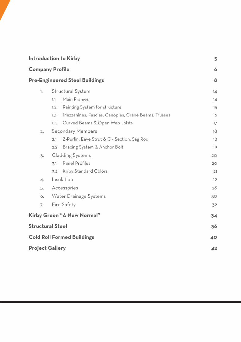
Introduction to Kirby 5
Company Profile 6
Pre-Engineered Steel Buildings 8
1. Structural System 14
1.1 Main Frames 14
1.2 Painting System for structure 15
1.3 Mezzanines, Fascias, Canopies, Crane Beams, Trusses 16
1.4 Curved Beams & Open Web Joists 17
2. Secondary Members 18
2.1 Z-Purlin, Eave Strut & C - Section, Sag Rod 18
2.2 Bracing System & Anchor Bolt 19
3. Cladding Systems 20
3.1 Panel Profiles 20
3.2 Kirby Standard Colors 21
4. Insulation 22
5. Accessories 28
6. Water Drainage Systems 30
7. Fire Safety 32
Kirby Green “A New Normal” 34
Structural Steel 36
Cold Roll Formed Buildings 40
Project Gallery 42
5
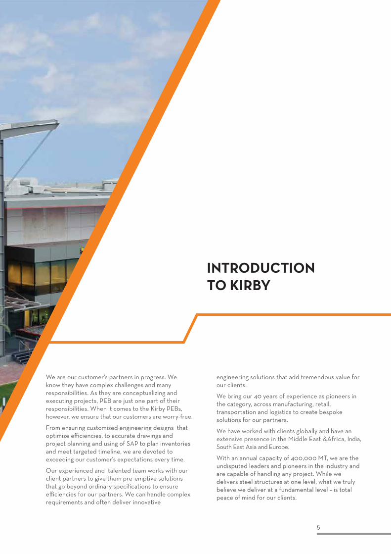
INTRODUCTION TO KIRBY
We are our customer’s partners in progress. We know they have complex challenges and many responsibilities. As they are conceptualizing and executing projects, PEB are just one part of their responsibilities. When it comes to the Kirby PEBs, however, we ensure that our customers are worry-free.
From ensuring customized engineering designs that optimize efficiencies, to accurate drawings and project planning and using of SAP to plan inventories and meet targeted timeline, we are devoted to exceeding our customer’s expectations every time.
Our experienced and talented team works with our client partners to give them pre-emptive solutions that go beyond ordinary specifications to ensure efficiencies for our partners. We can handle complex requirements and often deliver innovative
engineering solutions that add tremendous value for our clients.
We bring our 40 years of experience as pioneers in the category, across manufacturing, retail, transportation and logistics to create bespoke solutions for our partners.
We have worked with clients globally and have an extensive presence in the Middle East &Africa, India, South East Asia and Europe.
With an annual capacity of 400,000 MT, we are the undisputed leaders and pioneers in the industry and are capable of handling any project. While we delivers steel structures at one level, what we truly believe we deliver at a fundamental level – is total peace of mind for our clients.
6
COMPANY PROFILE
VISION MISSION
At Kirby, we believe in going above and beyond our clients’ expectation to deliver outstanding service and quality, everytime. Customer delight is the cornerstone of each action we take and building the future Together.
We are the world’s no.1 choice for PEBs due to our commitment to excellence in quality and engineering design and we want to pre-empt our customer’s needs in design, innovation and delivery.
Kirby Building Systems established in 1976 is a global leader in the design and manufacturing of pre-engineered steel buildings and structures, offering customers a wide range of customized, cost-effective steel building solutions. Kirby’s global spread extends across Middle East, Africa, Asia, Indian subcontinent and South East Asia with production capacity exceeding 400,000 MT annually, operations across 70 countries and workforce of 4,000 people.
Kirby globally offers one of the most comprehensive product portfolios ranging from pre-engineered steel building, structural steel and storage solutions. We offer a wide range of steel solutions tailored to our customers’ specific needs including
pre-engineering steel buildings, storage solutions/industrial racking systems, and broad array of our steel building products that cover applications in major market segments including heavy industry, infrastructure, high-rise buildings, warehouse, factories, oil and gas and leisure structures.
Kirby South East Asia has been doing business since 1999 and started operation in Vietnam from 2008, with its 50,000 MT annum capacity plant in Vietnam. Kirby South East Asia has supplied and built over 500 buildings through Vietnam, Singapore, Malaysia, Indonesia, Thailand, Philippines, Laos, Cambodia, Australia, Nigeria, Ethiopia, Tanzania and Myanmar.
1976
First Kirby plant start production in Kurwait
2000
Inauguration of Hyderabad Plant, India
2006
Inauguration of Kirby Haridwar Plant, India
2007
Inauguration of Ras Al Khaimah Plant, UAE
7
CERTIFICATIONS
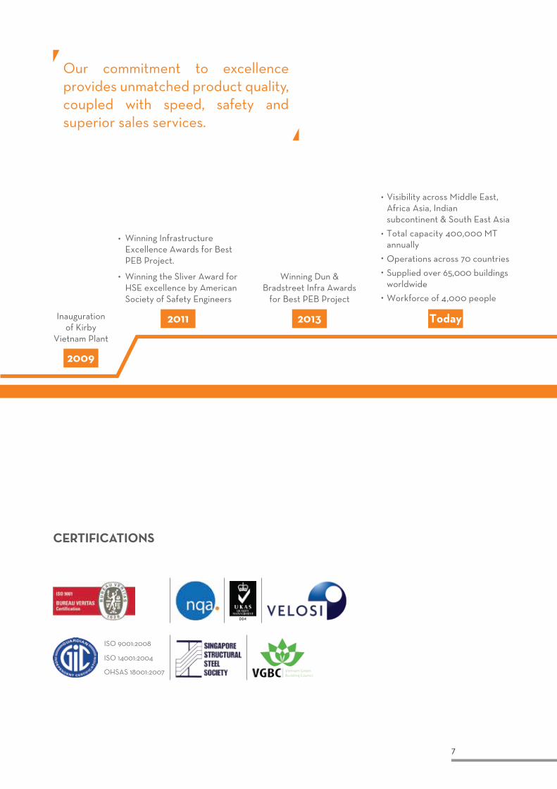
Our commitment to excellence provides unmatched product quality, coupled with speed, safety and superior sales services.
2009
Today20132011Inauguration of Kirby
Vietnam Plant
Winning Dun & Bradstreet Infra Awards
for Best PEB Project
Winning Infrastructure Excellence Awards for Best PEB Project.
Winning the Sliver Award for HSE excellence by American Society of Safety Engineers
Visibility across Middle East, Africa Asia, Indian subcontinent & South East Asia
Total capacity 400,000 MT annually
Operations across 70 countries
Supplied over 65,000 buildings worldwide
Workforce of 4,000 people
ISO 9001:2008
ISO 14001:2004
OHSAS 18001:2007
8
PRE-ENGINEERED STEEL BUILDINGS
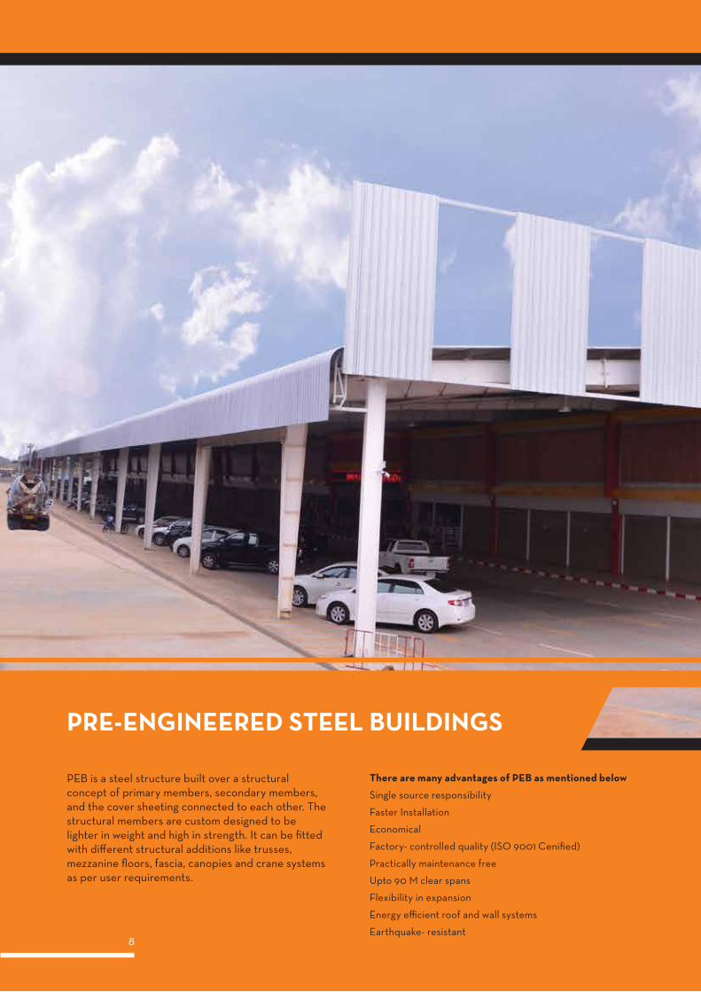
PEB is a steel structure built over a structural concept of primary members, secondary members, and the cover sheeting connected to each other. The structural members are custom designed to be lighter in weight and high in strength. It can be fitted with different structural additions like trusses, mezzanine floors, fascia, canopies and crane systems as per user requirements.
There are many advantages of PEB as mentioned below
Single source responsibility
Faster Installation
Economical
Factory- controlled quality (ISO 9001 Cenified)
Practically maintenance free
Upto 90 M clear spans
Flexibility in expansion
Energy efficient roof and wall systems
Earthquake- resistant
9
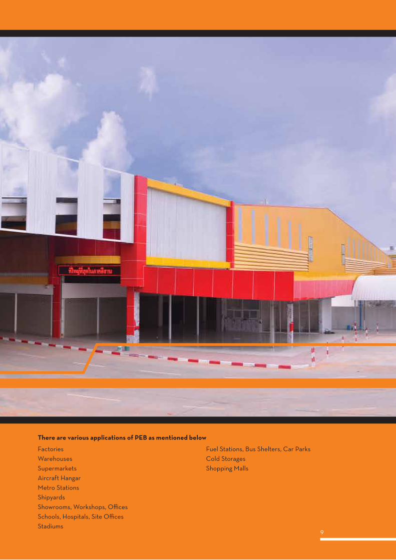
There are various applications of PEB as mentioned below
FactoriesWarehousesSupermarketsAircraft HangarMetro StationsShipyardsShowrooms, Workshops, OfficesSchools, Hospitals, Site OfficesStadiums
Fuel Stations, Bus Shelters, Car ParksCold StoragesShopping Malls
10
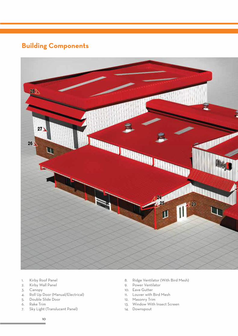
Building Components
1. Kirby Roof Panel2. Kirby Wall Panel3. Canopy4. Roll Up Door (Manual/Electrical)5. Double Slide Door6. Rake Trim7. Sky Light (Translucent Panel)
8. Ridge Ventilator (With Bird Mesh)9. Power Ventilator10. Eave Gutter11. Louver with Bird Mesh12. Masonry Trim13. Window With Insect Screen14. Downspout
11
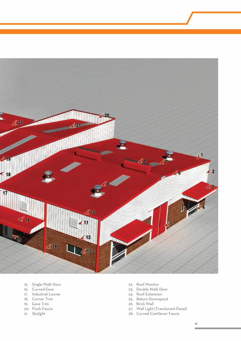
15. Single Walk Door16. Curved Eave17. Industrial Louver18. Corner Trim19. Eave Trim20. Flush Fascia21. Skylight
22. Roof Monitor23. Double Walk Door24. Roof Extension25. Return Downspout26. Brick Wall27. Wall Light (Translucent Panel)28. Curved Cantilever Fascia
12
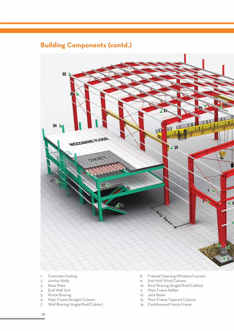
Building Components (contd.)
1. Concrete Footing2. Anchor Bolts3. Base Plate4. End Wall Girt5. Portal Bracing6. Main Frame Straight Column7. Wall Bracing (Angle/Rod/Cables)
8. Framed Opening (Window/Louver)9. End Wall Wind Column10. Roof Bracing (Angle/Rod/Cables)11. Main Frame Rafter12. Jack Beam13. Main Frame Tapered Column14. Cantilevered Fascia Frame
13
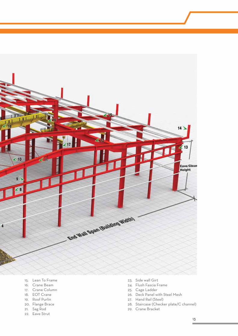
15. Lean To Frame 16. Crane Beam17. Crane Column18. EOT Crane19. Roof Purlin20. Flange Brace21. Sag Rod22. Eave Strut
23. Side wall Girt24. Flush Fascia Frame25. Cage Ladder26. Deck Panel with Steel Mesh27. Hand Rail (Steel)28. Staircase (Checker plate/C channel)29. Crane Bracket
14
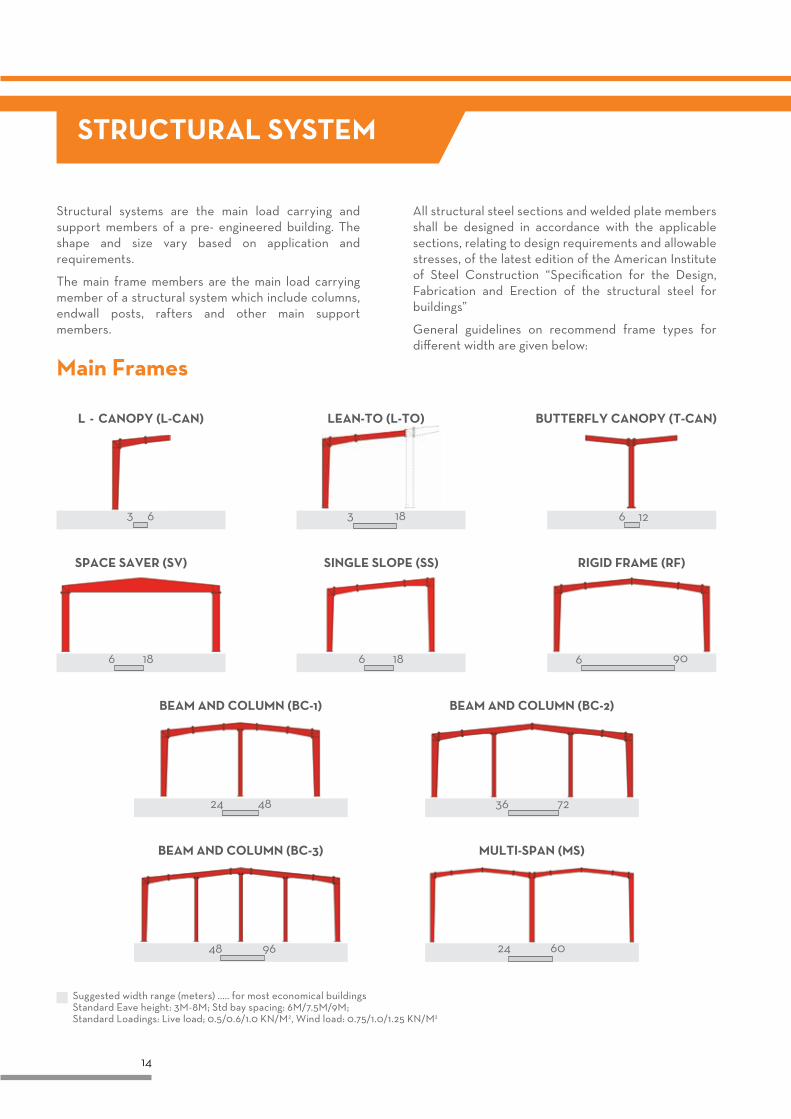
Suggested width range (meters) ..... for most economical buildingsStandard Eave height: 3M-8M; Std bay spacing: 6M/7.5M/9M;Standard Loadings: Live load; 0.5/0.6/1.0 KN/M2, Wind load: 0.75/1.0/1.25 KN/M2
Main Frames
Structural systems are the main load carrying and support members of a pre- engineered building. The shape and size vary based on application and requirements.
The main frame members are the main load carrying member of a structural system which include columns, endwall posts, rafters and other main support members.
All structural steel sections and welded plate members shall be designed in accordance with the applicable sections, relating to design requirements and allowable stresses, of the latest edition of the American Institute of Steel Construction “Specification for the Design, Fabrication and Erection of the structural steel for buildings”
General guidelines on recommend frame types for different width are given below:
STRUCTURAL SYSTEM
15
Painting systemIn the steel construction sector, the same types of paint are used from project to project. Each type of paint is designed to meet specific needs to satisfy the particular requirements of each individual project. Paint finishes can be used for aesthetic purposes, permanent or temporary protection, and colour identification.
A paint consists of a particular pigment, dispersed in a particular binder, dissolved in a particular solvent then the number of generic types of paint is limited. The most common method of classifying is by their binder type.
The three most important binders (resins) used in modern paints are Acrylic, Alkyd and Epoxy polymers
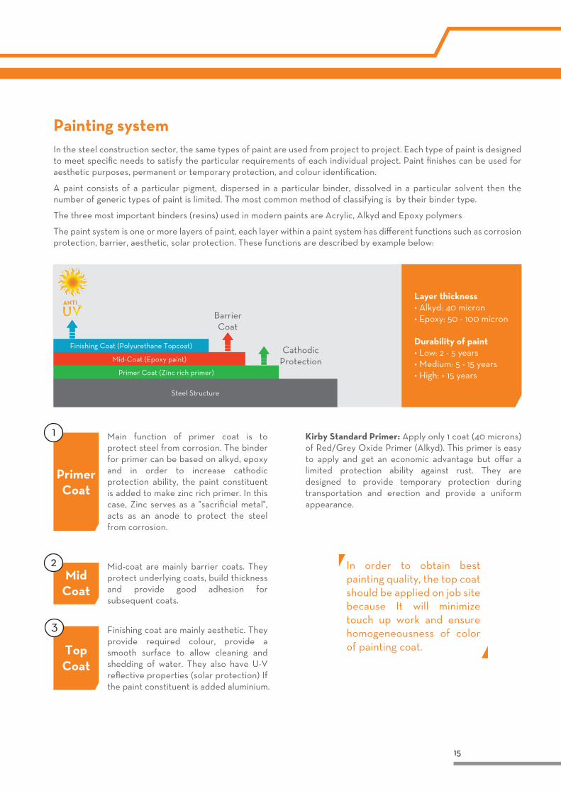
The paint system is one or more layers of paint, each layer within a paint system has different functions such as corrosion protection, barrier, aesthetic, solar protection. These functions are described by example below:
Main function of primer coat is to protect steel from corrosion. The binder for primer can be based on alkyd, epoxy and in order to increase cathodic protection ability, the paint constituent is added to make zinc rich primer. In this case, Zinc serves as a "sacrificial metal", acts as an anode to protect the steel from corrosion.
Finishing coat are mainly aesthetic. They provide required colour, provide a smooth surface to allow cleaning and shedding of water. They also have U-V reflective properties (solar protection) If the paint constituent is added aluminium.
Mid-coat are mainly barrier coats. They protect underlying coats, build thickness and provide good adhesion for subsequent coats.
Kirby Standard Primer: Apply only 1 coat (40 microns) of Red/Grey Oxide Primer (Alkyd). This primer is easy to apply and get an economic advantage but offer a limited protection ability against rust. They are designed to provide temporary protection during transportation and erection and provide a uniform appearance.
Primer Coat
Mid Coat
Top Coat
Finishing Coat (Polyurethane Topcoat)
Mid-Coat (Epoxy paint)
Barrier Coat
Cathodic Protection
Primer Coat (Zinc rich primer)
Steel Structure
Layer thickness• Alkyd: 40 micron• Epoxy: 50 - 100 micron
Durability of paint• Low: 2 - 5 years• Medium: 5 - 15 years• High: > 15 years
In order to obtain best painting quality, the top coat should be applied on job site because It will minimize touch up work and ensure homogeneousness of color of painting coat.
16
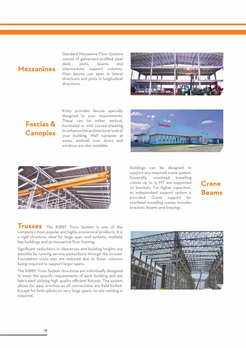
Mezzanines
Standard Mezzanine Floor Systems consist of galvanized profiled steel deck, joists, beams and intermediate support columns. Main beams can span in lateral directions and joists in longitudinal directions.
Trusses The KIRBY Truss System is one of the company’s most popular and highly economical products. It is a rigid structure, ideal for large span roof systems, multiple bay buildings and as mezzanine floor framing.
Significant reductions in clearances and building heights are possible by running service pipes/ducts through the trusses. Foundation costs also are reduced due to fewer columns being required to support larger spans.
The KIRBY Truss System structures are individually designed to meet the specific requirements of each building and are fabricated utilizing high quality efficient fixtures. The system allows for easy erection as all connections are field bolted. Except for field splices on very large spans, no site welding is required.
Kirby provides fascias specially designed to your requirements. These can be either vertical, horizontal or with curved sheeting to enhance the architectural look of your building. Wall canopies at eaves, endwall, over doors and windows are also available.
Fascias & Canopies
Buildings can be designed to support any required crane system. Generally, overhead travelling cranes up to 15 MT are supported on brackets. For higher capacities, an independent support system is provided. Crane support for overhead travelling cranes includes brackets, beams and bracings.
Crane Beams
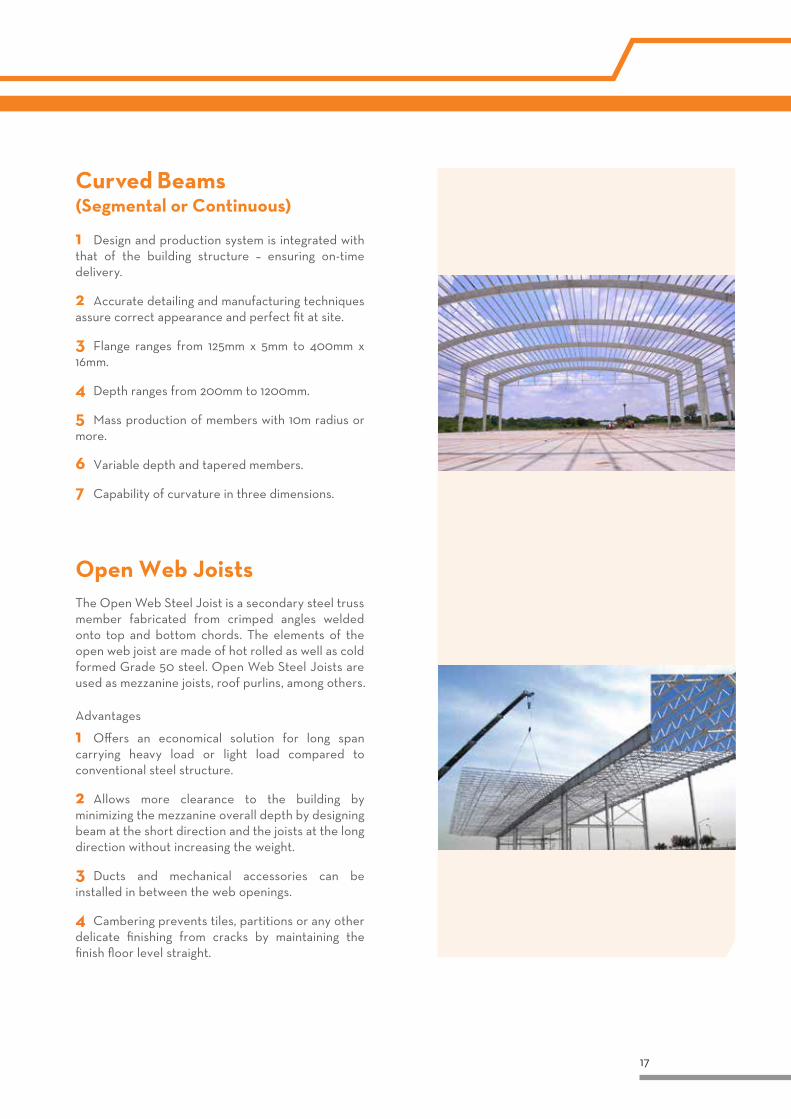
Curved Beams(Segmental or Continuous)
1 Design and production system is integrated with that of the building structure – ensuring on-time delivery.
2 Accurate detailing and manufacturing techniques assure correct appearance and perfect fit at site.
3 Flange ranges from 125mm x 5mm to 400mm x 16mm.
4 Depth ranges from 200mm to 1200mm.
5 Mass production of members with 10m radius or more.
6 Variable depth and tapered members.
7 Capability of curvature in three dimensions.
Open Web Joists
Advantages
1 Offers an economical solution for long span carrying heavy load or light load compared to conventional steel structure.
2 Allows more clearance to the building by minimizing the mezzanine overall depth by designing beam at the short direction and the joists at the long direction without increasing the weight.
3 Ducts and mechanical accessories can be installed in between the web openings.
4 Cambering prevents tiles, partitions or any other delicate finishing from cracks by maintaining the finish floor level straight.
The Open Web Steel Joist is a secondary steel truss member fabricated from crimped angles welded onto top and bottom chords. The elements of the open web joist are made of hot rolled as well as cold formed Grade 50 steel. Open Web Steel Joists are used as mezzanine joists, roof purlins, among others.
17
18
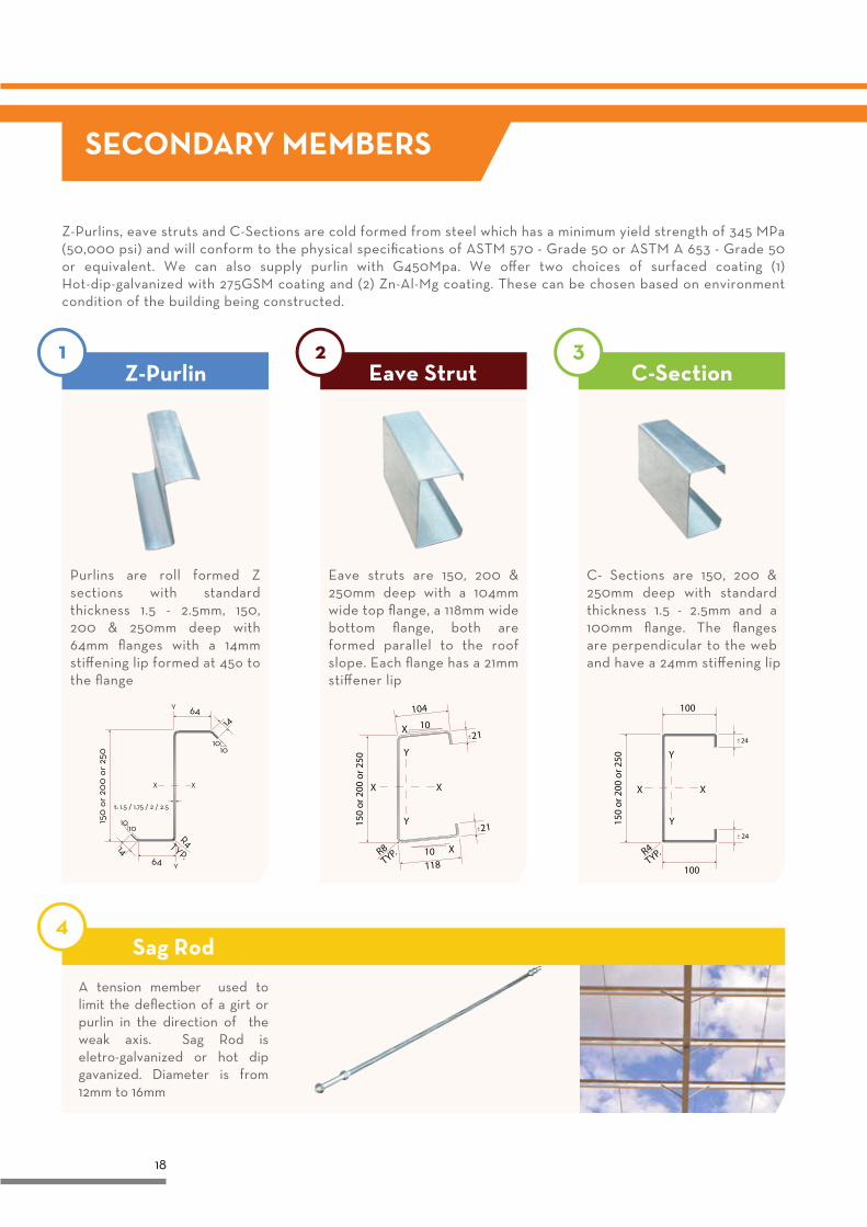
Z-Purlins, eave struts and C-Sections are cold formed from steel which has a minimum yield strength of 345 MPa (50,000 psi) and will conform to the physical specifications of ASTM 570 - Grade 50 or ASTM A 653 - Grade 50 or equivalent. We can also supply purlin with G450Mpa. We offer two choices of surfaced coating (1) Hot-dip-galvanized with 275GSM coating and (2) Zn-Al-Mg coating. These can be chosen based on environment condition of the building being constructed.
SECONDARY MEMBERS
A tension member used to limit the deflection of a girt or purlin in the direction of the weak axis. Sag Rod is eletro-galvanized or hot dip gavanized. Diameter is from 12mm to 16mm
21
Y
Y
X
X
X
X
150
or 2
00 o
r 250
R8TYP.
21
10
10
104
118
150
or 2
00 o
r 250
100
100
Y
Y
X X
24
24
R4TYP.
1010
10
14
14
64Y
Y64
XX
t: 1.5 / 1.75 / 2 / 2.5
R4TYP.
150
or
200
or
250
10
Purlins are roll formed Z sections with standard thickness 1.5 - 2.5mm, 150, 200 & 250mm deep with 64mm flanges with a 14mm stiffening lip formed at 45o to the flange
Eave struts are 150, 200 & 250mm deep with a 104mm wide top flange, a 118mm wide bottom flange, both are formed parallel to the roof slope. Each flange has a 21mm stiffener lip
C- Sections are 150, 200 & 250mm deep with standard thickness 1.5 - 2.5mm and a 100mm flange. The flanges are perpendicular to the web and have a 24mm stiffening lip
Sag Rod
19
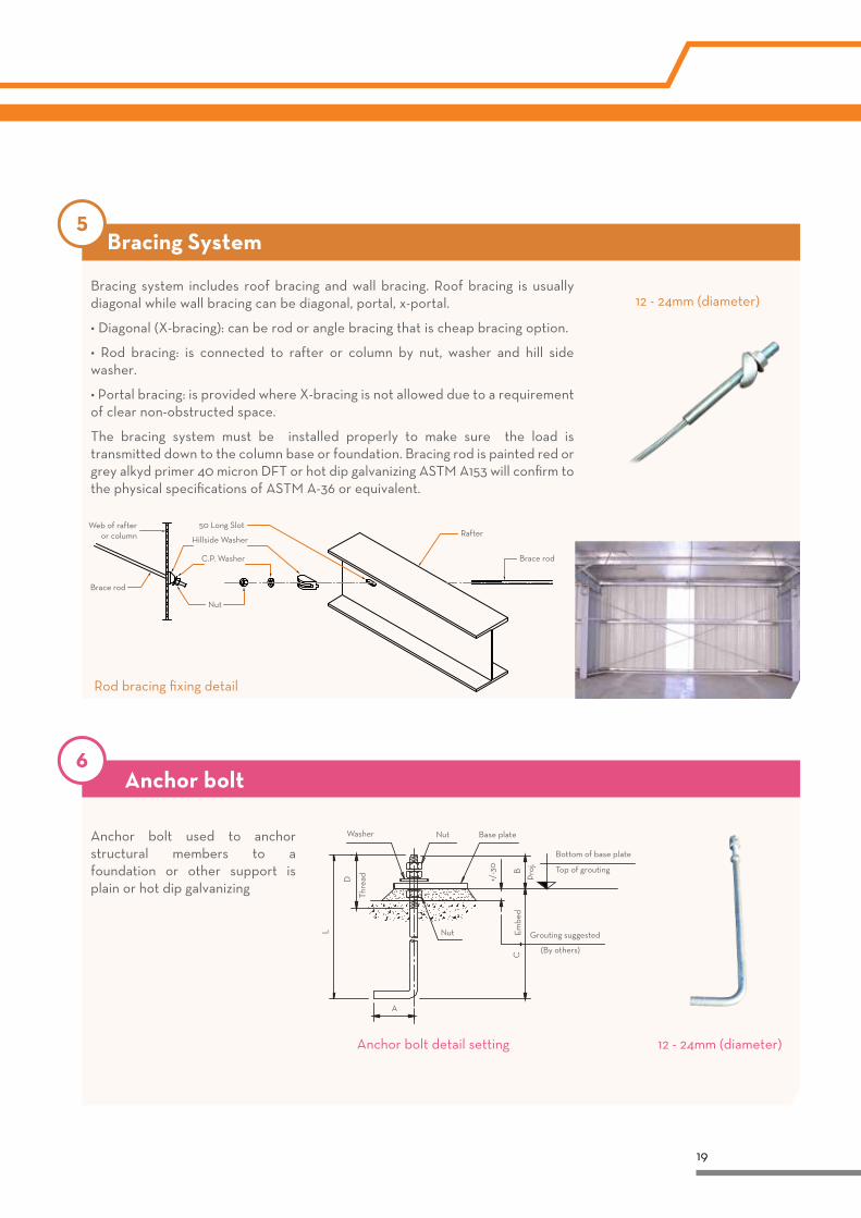
Bracing system includes roof bracing and wall bracing. Roof bracing is usually diagonal while wall bracing can be diagonal, portal, x-portal.
• Diagonal (X-bracing): can be rod or angle bracing that is cheap bracing option.
• Rod bracing: is connected to rafter or column by nut, washer and hill side washer.
• Portal bracing: is provided where X-bracing is not allowed due to a requirement of clear non-obstructed space.
The bracing system must be installed properly to make sure the load is transmitted down to the column base or foundation. Bracing rod is painted red or grey alkyd primer 40 micron DFT or hot dip galvanizing ASTM A153 will confirm to the physical specifications of ASTM A-36 or equivalent.
Bracing System
12 - 24mm (diameter)
Anchor bolt
Anchor bolt used to anchor structural members to a foundation or other support is plain or hot dip galvanizing
12 - 24mm (diameter)Anchor bolt detail setting
Washer Base plate
Bottom of base plate
Top of grouting
Grouting suggested
(By others)
Nut
Nut
A
Thre
adD
L
CB
+/-3
0
Proj
.
Embe
d50 Long Slot
Hillside Washer
Web of rafter or column
Brace rod
Rafter
C.P. Washer Brace rod
Nut
Rod bracing fixing detail
90
28.1
55 22
29.790
240900 mm
R=3
4.55
24030.25
20.2
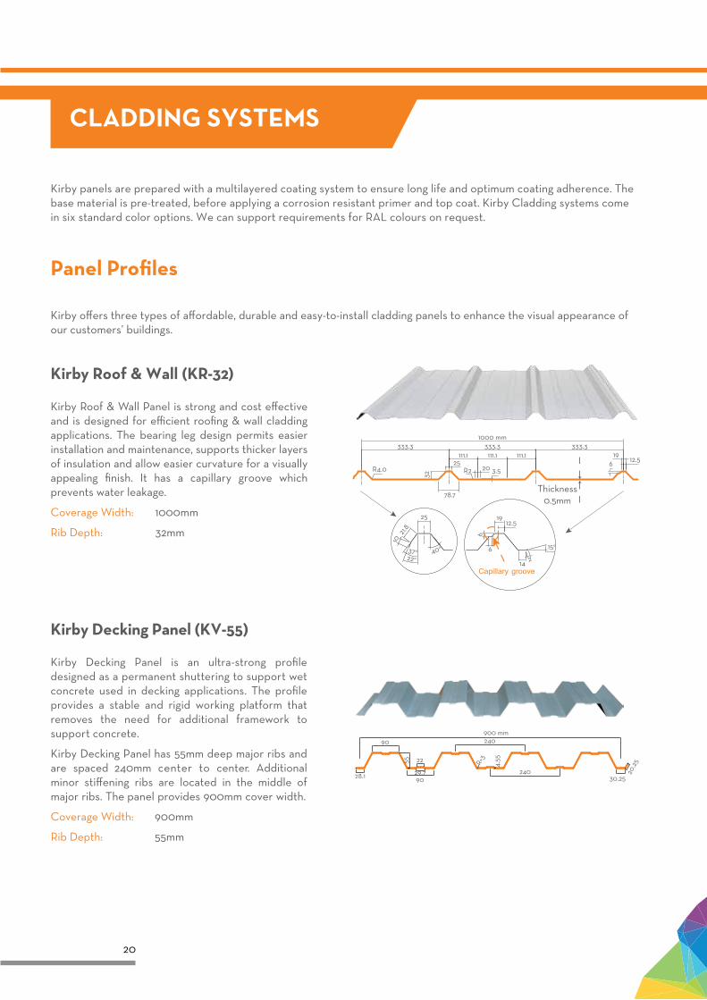
5Kirby Decking Panel (KV-55)
Kirby Decking Panel is an ultra-strong profile designed as a permanent shuttering to support wet concrete used in decking applications. The profile provides a stable and rigid working platform that removes the need for additional framework to support concrete.
Kirby Decking Panel has 55mm deep major ribs and are spaced 240mm center to center. Additional minor stiffening ribs are located in the middle of major ribs. The panel provides 900mm cover width.
Coverage Width: 900mm
Rib Depth: 55mm
20
CLADDING SYSTEMS
Panel Profiles
Kirby Roof & Wall (KR-32)
Kirby Roof & Wall Panel is strong and cost effective and is designed for efficient roofing & wall cladding applications. The bearing leg design permits easier installation and maintenance, supports thicker layers of insulation and allow easier curvature for a visually appealing finish. It has a capillary groove which prevents water leakage.
Coverage Width: 1000mm
Rib Depth: 32mm
1000 mm333.3
111.1 111.1 111.1333.3 333.3
19
62
6
12.5
14
15o
3.520R225
78.7
32
25
21.8
10
37o 40o
22o
R4.0
196 12.5
Thickness0.5mm
Capillary groove
Kirby offers three types of affordable, durable and easy-to-install cladding panels to enhance the visual appearance of our customers’ buildings.
Kirby panels are prepared with a multilayered coating system to ensure long life and optimum coating adherence. The base material is pre-treated, before applying a corrosion resistant primer and top coat. Kirby Cladding systems come in six standard color options. We can support requirements for RAL colours on request.
21
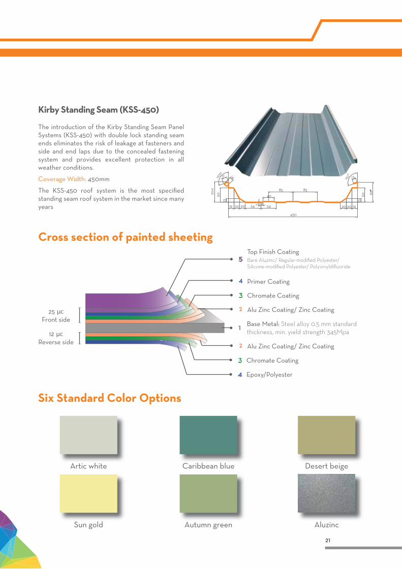
Six Standard Color Options
Artic white Caribbean blue
Sun gold Autumn green Aluzinc
Desert beige
Kirby Standing Seam (KSS-450)
The introduction of the Kirby Standing Seam Panel Systems (KSS-450) with double lock standing seam ends eliminates the risk of leakage at fasteners and side and end laps due to the concealed fastening system and provides excellent protection in all weather conditions.
Coverage Width: 450mm
The KSS-450 roof system is the most specified standing seam roof system in the market since many years 19 20 20
13
5070+1
110o
17 14
54 3 7 54
40
85 85
20 20 19
1350
13110O
69+1
450
Cross section of painted sheeting
12 µc Reverse side
25 µc Front side
Base Metal: Steel alloy 0.5 mm standard thickness, min. yield strength 345Mpa
Alu Zinc Coating/ Zinc Coating
Alu Zinc Coating/ Zinc Coating
Chromate Coating
Chromate Coating
Epoxy/Polyester
Primer Coating
Top Finish CoatingBare Aluzinc/ Regular-modified Polyester/ Silicone-modified Polyester/ Polyvinyldifluoride
22
Density (kg/m3)
Thickness (mm)
Length (m)
Width (m)
Working temperature range
Thermal conductivity (W/m.K, 50oC)
Fireproof
Moisture absorption
10 - 48
25 - 100
10 - 45
0.4 - 0.6 - 1.0 - 1.2
0.055 - 0.035
Grade A
<1% (BS2972, ASTM C1104/ 1104 M) <1% (BS2972, ASTM C1104/ 1104 M)
80oC - 100oC - 230oC
36 - 48 - 64
40 - 100
5 - 10
1.1 - 1.2
Grade A
100oC - 750oC
0.047 - 0.038
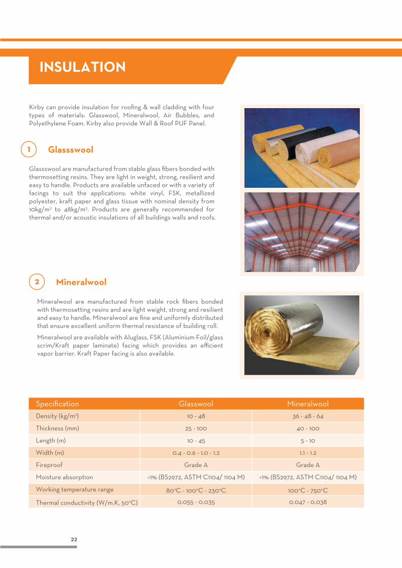
Specification Glasswool Mineralwool
INSULATION
Kirby can provide insulation for roofing & wall cladding with four types of materials: Glasswool, Mineralwool, Air Bubbles, and Polyethylene Foam. Kirby also provide Wall & Roof PUF Panel.
Glassswool are manufactured from stable glass fibers bonded with thermosetting resins. They are light in weight, strong, resilient and easy to handle. Products are available unfaced or with a variety of facings to suit the applications: white vinyl, FSK, metallized polyester, kraft paper and glass tissue with nominal density from 10kg/m3 to 48kg/m3. Products are generally recommended for thermal and/or acoustic insulations of all buildings walls and roofs.
Glassswool
Mineralwool are manufactured from stable rock fibers bonded with thermosetting resins and are light weight, strong and resilient and easy to handle. Mineralwool are fine and uniformly distributed that ensure excellent uniform thermal resistance of building roll.
Mineralwool are available with Aluglass, FSK (Aluminium Foil/glass scrim/Kraft paper laminate) facing which provides an efficient vapor barrier. Kraft Paper facing is also available.
Mineralwool
23
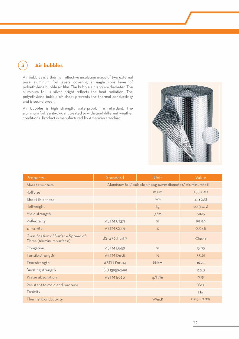
Air bubbles is a thermal reflective insulation made of two external pure aluminum foil layers covering a single core layer of polyethylene bubble air film. The bubble air is 10mm diameter. The aluminum foil is silver bright reflects the heat radiation. The polyethylene bubble air sheet prevents the thermal conductivity and is sound proof.
Air bubbles is high strength, waterproof, fire retardant. The aluminum foil is anti-oxidant treated to withstand different weather conditions. Product is manufactured by American standard.
Property Standard Unit Value
Air bubbles
24
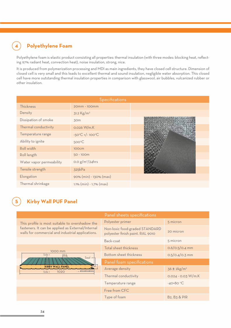
Polyethylene foam is elastic product consisting all properties: thermal insulation (with three modes: blocking heat, reflect-ing 97% radiant heat, convection heat), noise insulation, strong, nice.
It is produced from polymerization processing and MDI as main ingredients, they have closed cell structure. Dimension of closed cell is very small and this leads to excellent thermal and sound insulation, negligible water absorption. This closed cell have more outstanding thermal insulation properties in comparison with glasswool, air bubbles, vulcanized rubber or other insulation.
Polyethylene Foam
Kirby Wall PUF Panel
KIRBY WALL PANEL
1000 mm
1020
SealSide 1
Side 1
62.5
62.5 62.5 62.5
This profile is most suitable to overshadow the fasteners. It can be applied as External/Internal walls for commercial and industrial applications.
Panel sheets specifications
Panel foam specifications
Specifications
25
l l l
p p p
l
p
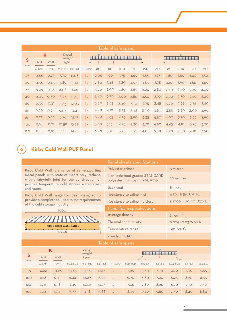
Table of safe spans
Kirby Cold Wall PUF Panel
Kirby Cold Wall is a range of self-supporting metal panels with state-of-theart polyurethane with a labyrinth joint for the construction of positive temperature cold storage warehouses and rooms.
Kirby Cold Wall range has been designed to provide a complete solution to the requirements of the cold storage industry
≥ 1000 h (ASTM D2247)
Resistance to saline mist
Resistance to saline moisture
≥ 500 h (ECCA T8)
38kg/m3
0.024 - 0.03 W/m.K
Panel sheets specifications
Panel foam specifications1000
1022,6
KIRBY COLD WALL PANEL
l
p
Table of safe spans
26
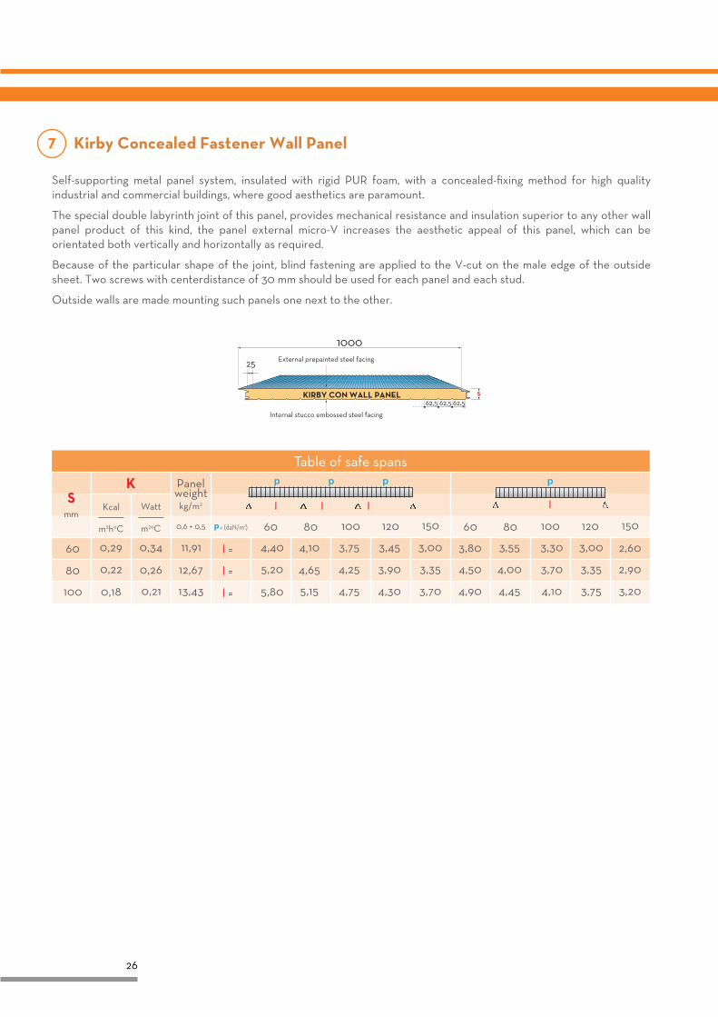
Self-supporting metal panel system, insulated with rigid PUR foam, with a concealed-fixing method for high quality industrial and commercial buildings, where good aesthetics are paramount.
The special double labyrinth joint of this panel, provides mechanical resistance and insulation superior to any other wall panel product of this kind, the panel external micro-V increases the aesthetic appeal of this panel, which can be orientated both vertically and horizontally as required.
Because of the particular shape of the joint, blind fastening are applied to the V-cut on the male edge of the outside sheet. Two screws with centerdistance of 30 mm should be used for each panel and each stud.
Outside walls are made mounting such panels one next to the other.
S
1000External prepainted steel facing
Internal stucco embossed steel facing
25
62,562,562,5KIRBY CON WALL PANEL
l l l
p p p
l
p
Table of safe spans
Kirby Concealed Fastener Wall Panel
27
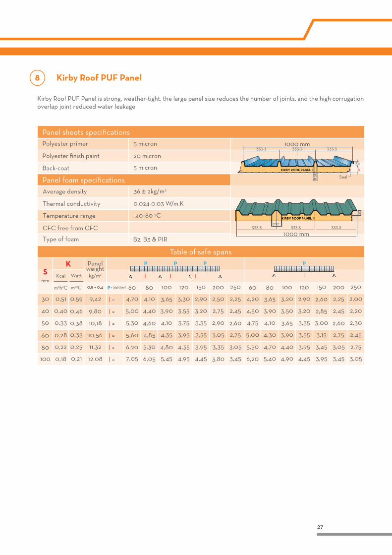
Kirby Roof PUF Panel
Kirby Roof PUF Panel is strong, weather-tight, the large panel size reduces the number of joints, and the high corrugation overlap joint reduced water leakage
KIRBY ROOF PANEL I
1000 mm333.3
38
2040 Seal
S
333.3333.3
KIRBY ROOF PANEL II
1000 mm
32
78.7333.3333.3333.3
Panel sheets specifications
Panel foam specifications
Table of safe spans
l l l
p p p
l
p
28
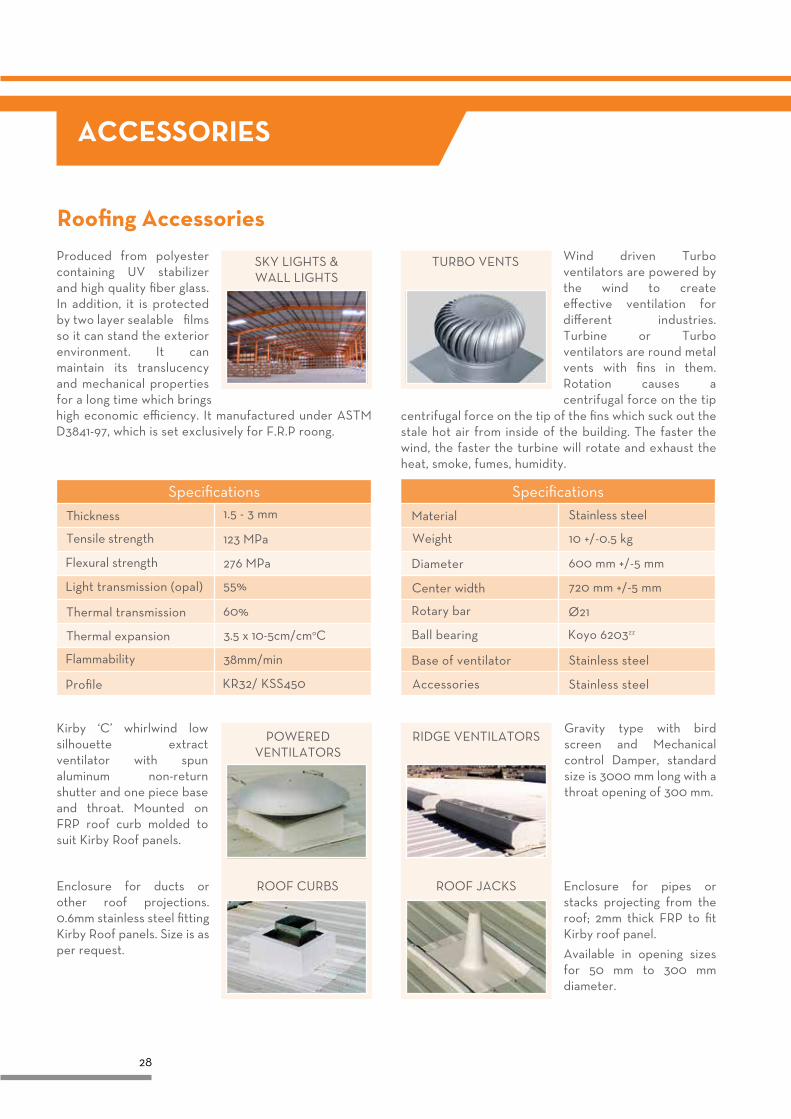
Roofing Accessories
ACCESSORIES
high economic efficiency. It manufactured under ASTM D3841-97, which is set exclusively for F.R.P roong.
centrifugal force on the tip of the fins which suck out the stale hot air from inside of the building. The faster the wind, the faster the turbine will rotate and exhaust the heat, smoke, fumes, humidity.
Wind driven Turbo ventilators are powered by the wind to create effective ventilation for different industries. Turbine or Turbo ventilators are round metal vents with fins in them. Rotation causes a centrifugal force on the tip
Produced from polyester containing UV stabilizer and high quality fiber glass. In addition, it is protected by two layer sealable �films so it can stand the exterior environment. It can maintain its translucency and mechanical properties for a long time which brings
SKY LIGHTS &WALL LIGHTS
TURBO VENTS
Kirby ‘C’ whirlwind low silhouette extract ventilator with spun aluminum non-return shutter and one piece base and throat. Mounted on FRP roof curb molded to suit Kirby Roof panels.
Enclosure for ducts or other roof projections. 0.6mm stainless steel fitting Kirby Roof panels. Size is as per request.
Enclosure for pipes or stacks projecting from the roof; 2mm thick FRP to fit Kirby roof panel.
Available in opening sizes for 50 mm to 300 mm diameter.
Gravity type with bird screen and Mechanical control Damper, standard size is 3000 mm long with a throat opening of 300 mm.
POWERED VENTILATORS
RIDGE VENTILATORS
ROOF JACKSROOF CURBS
SpecificationsSpecifications
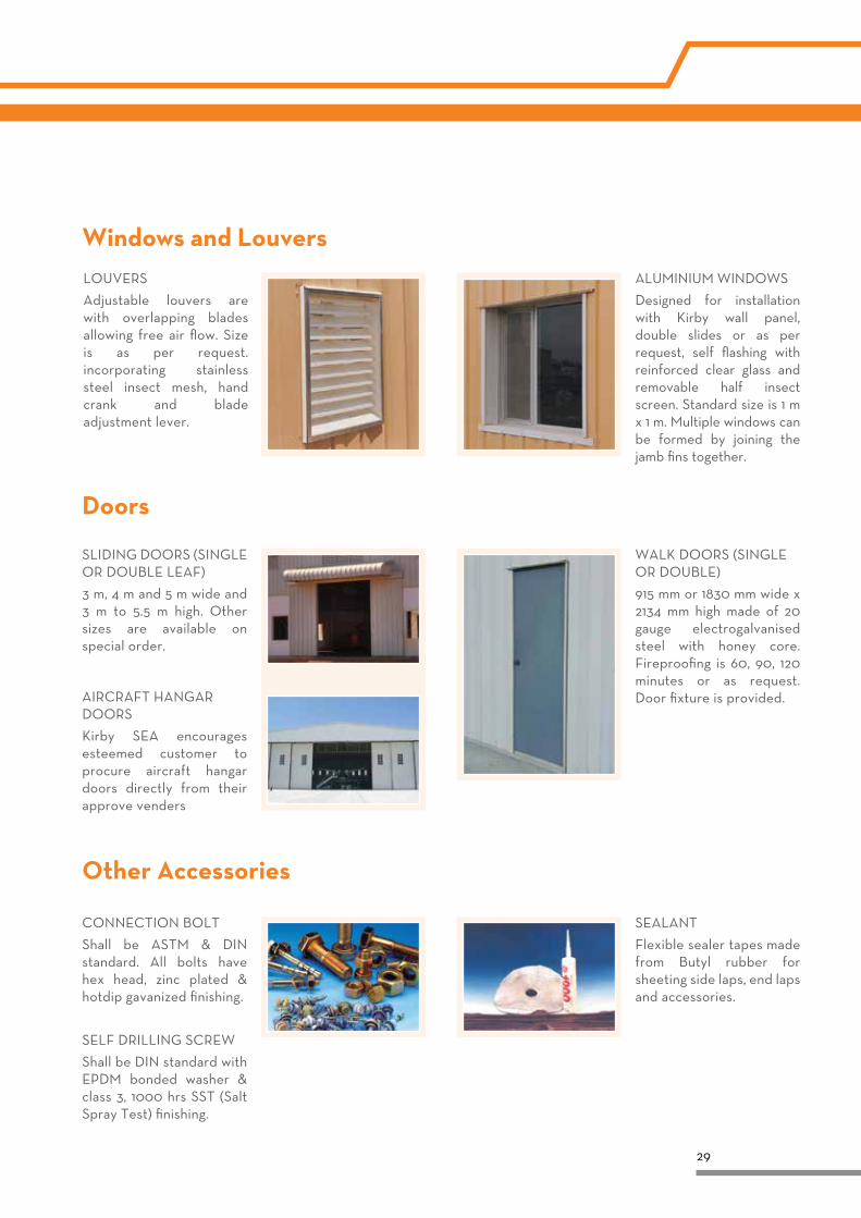
Windows and Louvers
29
LOUVERS
Adjustable louvers are with overlapping blades allowing free air flow. Size is as per request. incorporating stainless steel insect mesh, hand crank and blade adjustment lever.
ALUMINIUM WINDOWS
Designed for installation with Kirby wall panel, double slides or as per request, self flashing with reinforced clear glass and removable half insect screen. Standard size is 1 m x 1 m. Multiple windows can be formed by joining the jamb fins together.
Doors
SLIDING DOORS (SINGLE OR DOUBLE LEAF)
3 m, 4 m and 5 m wide and 3 m to 5.5 m high. Other sizes are available on special order.
AIRCRAFT HANGAR DOORS
Kirby SEA encourages esteemed customer to procure aircraft hangar doors directly from their approve venders
WALK DOORS (SINGLE OR DOUBLE)
915 mm or 1830 mm wide x 2134 mm high made of 20 gauge electrogalvanised steel with honey core. Fireproofing is 60, 90, 120 minutes or as request. Door fixture is provided.
Other Accessories
CONNECTION BOLT
Shall be ASTM & DIN standard. All bolts have hex head, zinc plated & hotdip gavanized finishing.
SELF DRILLING SCREW
Shall be DIN standard with EPDM bonded washer & class 3, 1000 hrs SST (Salt Spray Test) finishing.
SEALANT
Flexible sealer tapes made from Butyl rubber for sheeting side laps, end laps and accessories.
30
WATER DRAINAGE
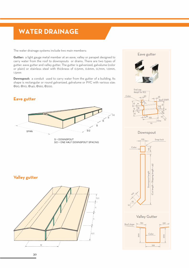
The water drainage systems include two main members:
Gutter: a light gauge metal member at an eave, valley or parapet designed to carry water from the roof to downspouts or drains. There are two types of gutter: eave gutter and valley gutter. The gutter is galvanized, galvalume (color or plain) or stainless steel with thickness of 0.5mm, 0.6mm, 0.7mm, 1.0mm, 1.5mm
Downspout: a conduit used to carry water from the gutter of a building. Its shape is rectangular or round galvanized, galvalume or PVC with various size: Ф90, Ф110, Ф140, Ф160, Ф200.
Valley gutter
Eave gutter
Eave gutter
Color 20 25
19155
215151
51
358
8
Roof slope
One
End capReqd. for R/L
10
10
7516
11
38
10
Valley Gutter
Roof slope130 130
Color
199
200
200
Downspout
Snap lock
Color
105
10
10
102
125
(Cut
leng
th =
Shi
ppin
g le
ngth
+ 4
5)
Dow
nspo
ut le
ngth
31
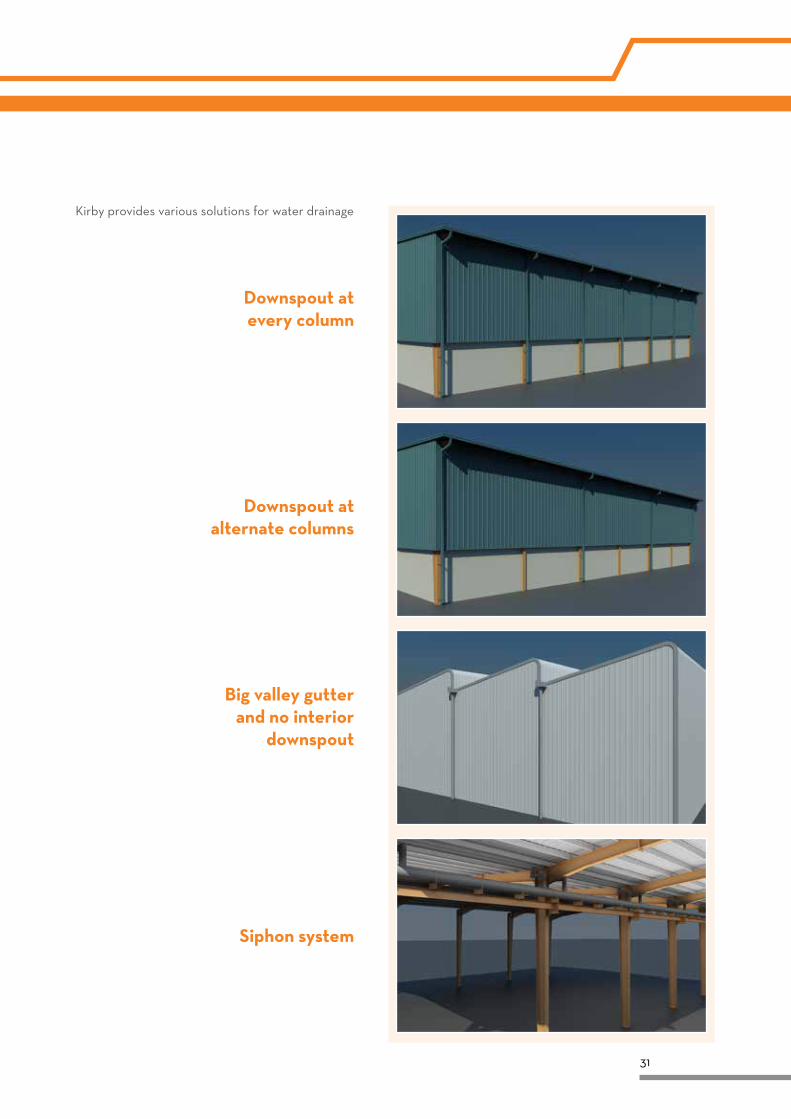
Kirby provides various solutions for water drainage
Downspout at every column
Downspout at alternate columns
Big valley gutter and no interior
downspout
Siphon system
32
FIRE SAFETY
Life safety • The load bearing capacity of the building can be suitable for a specific period of time to evacuate the people and critical items.
• The generation and spread of fire and smoke within the works are limited.
• The spread of fire to the neighbouring building is limited.
• The safety of rescue teams is taken into consideration.
Loss preventionThe implications of a fire on the continuing viability of a business can be substantial and consideration should be given to the limitation of damage to: The structure and fabric of the building; Building content; Ongoing business viability.
Ignitability this property determines the difficulty with which a material can be ignited from a small source of heat or flame;
Non-combustibility this property determines the difficulty with which a material burns, contributes heat to a fire, and produces smoke and toxic/irritant products of combustion;
Rate of heat release the rate of heat release determines the amount of fire effluent produced and the rate at which the effluent is transported throughout the building.
Flame spread This property indicates the speed at which flame spreads across the surface of a material;
Melting and shrinkage Some materials shrink away from the heat source and form molten droplets, which fall down and flame on contact with the fire, contributing to spread the fire front;
Corrosion Many materials used in steel building produce gases such as hydrogen chloride that corrode metals.
Environmental Protection • The effects of fire on adjacent buildings or facilities
• The release of hazardous materials into the environment, such as gaseous products of combustion and fibers into the atmosphere, or pollution of the groundwater due to fire-fighting operations
Factors taken while designing• Toxicity and irritancy of combustion products
• Temperature/radiation intensity of combustion products
• Obstruction caused by combustion products
• Protection of steel structure using paint and fire resistant boards
Catagorization of materials as per fire reaction (EN 13823):
Material Not combustible Moderately combustible
Class A1 A2 B C D E F
Combustible
FIRE SAFETY DESIGN
Kirby buildings are designed keeping in mind fire safety as the needs of customers. The selection of members while designing the building is done based on the provisions of code and customer’s need. With careful design, and selection suitable fire protection system can meet stringent fire requirements as important aspects.
“REACTION-TO-FIRE” CONCEPT
The reaction to fire is the degree of participation of a material to a fire to which it is subjected. Therefore it is a particular behaviour which takes on extreme importance in the early stages of a fire. In the growth phase of a fire, the following reaction-to-fire properties are important
33
“FIRE RESISTANCE” CONCEPTS
Intumescent fireproofing designed for the fire protection of steelwork for up to a 3 hour fire rating, depending on the design. The recommended use for this product is fireproofing of interior steel beams, columns. It must be applied over a compatible primer. It is not for use in exterior environments or for interior steelwork that will be exposed to freeze/thaw cycling or long-term surface temperatures over 140°F (60°C) in normal use.
Features:
• UL/ULC listed – designs for many types of steel sections. Up to 3 hour fire ratings for both interior
general purpose and interior conditioned space appications.
• Decorative finish – provides a smooth, decorative finish. Compatible topcoats available in a wide range of colors.
• Durable finish – provides a hard, dust free surface resistant to normal wear.
• Thin film coating – offers an economical solution to alternative fireproofing.
• VOC compliant
• Easy repair – if damaged it can be repaired easily using material as putty.
Features:
• Cementitious – Durable, remains in place during construction and beyond.
• Excellent film build – On all surfaces including columns, beams and decks.
• Applicator friendly – High film build, no alum required for increased coverage and easy clean-up.
• Mineral –Wool free – No airborne fibers.
• Alum and Chloride free – No special priming required.
• Styrene free – No toxic decomposition gasses.
• Economical – Maintains project on budget.
• Quality Manufactured – Under strict Carboline quality standards.
• Ready to Use – No site additives required.
Cementitious fireproofing supplied as a single powder component that is mixed with clean, potable water prior to application. It is designed to fireproof interior structural beams, joists, walls, roofs, decks, girders, columns.
While fire reaction is extremely important in the initial growth phase of a fire, fire resistance behaviour is important after flashover occurs. Fire resistance is the ability of maintaining the integrity of structure to:
• To resist collapse
• To resist the penetration of flames and hot gases while, at the same time, maintaining structural integrity
• To keep the unexposed face sufficiently cold so as not to ignite materials which come in contact with it
FIREPROOFING SYSTEM
Fireproofing system on structural steel can be cementitious or Intumescent coating. The thickness of fire paint depends on shape factor of the steel member cross section which is defined as a ratio of perimeter of section to the minimum thickness.
34
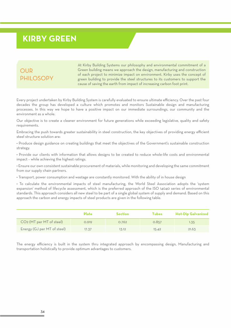
KIRBY GREEN
Every project undertaken by Kirby Building System is carefully evaluated to ensure ultimate efficiency. Over the past four decades the group has developed a culture which promotes and monitors Sustainable design and manufacturing processes. In this way we hope to have a positive impact on our immediate surroundings, our community and the environment as a whole.
Our objective is to create a cleaner environment for future generations while exceeding legislative, quality and safety requirements.
Embracing the push towards greater sustainability in steel construction, the key objectives of providing energy efficient steel structure solution are:
• Produce design guidance on creating buildings that meet the objectives of the Government’s sustainable construction strategy.
• Provide our clients with information that allows designs to be created to reduce whole-life costs and environmental impact – while achieving the highest ratings.
• Ensure our own consistent sustainable procurement of materials, while monitoring and developing the same commitment from our supply chain partners.
• Transport, power consumption and wastage are constantly monitored. With the ability of in house design
• To calculate the environmental impacts of steel manufacturing, the World Steel Association adopts the ‘system expansion’ method of lifecycle assessment, which is the preferred approach of the ISO 14040 series of environmental standards. This approach considers all new steel to be part of a single global system of supply and demand. Based on this approach the carbon and energy impacts of steel products are given in the following table.
The energy efficiency is built in the system thru integrated approach by encompassing design, Manufacturing and transportation holistically to provide optimum advantages to customers.
Plate
CO2 (MT per MT of steel)
Energy (GJ per MT of steel)
Section
0.919
17.37
0.762
13.12
0.857
15.42
1.35
21.63
Tubes Hot-Dip Galvanized
OUR PHILOSOPY
At Kirby Building Systems our philosophy and environmental commitment of a Green building means we approach the design, manufacturing and construction of each project to minimize impact on environment. Kirby uses the concept of green building to provide the steel structures to its customers to support the cause of saving the earth from impact of increasing carbon foot print.
35
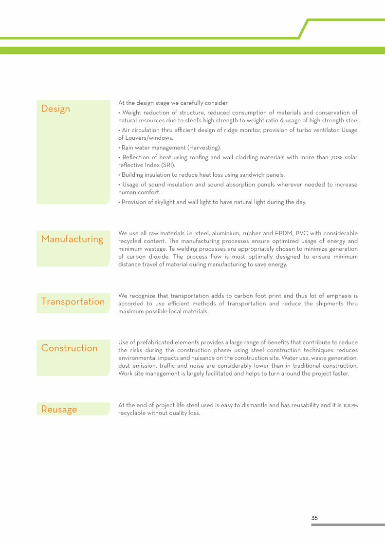
At the design stage we carefully consider
• Weight reduction of structure, reduced consumption of materials and conservation of natural resources due to steel’s high strength to weight ratio & usage of high strength steel.
• Air circulation thru efficient design of ridge monitor, provision of turbo ventilator, Usage of Louvers/windows.
• Rain water management (Harvesting).
• Reflection of heat using roofing and wall cladding materials with more than 70% solar reflective Index (SRI).
• Building insulation to reduce heat loss using sandwich panels.
• Usage of sound insulation and sound absorption panels wherever needed to increase human comfort.
• Provision of skylight and wall light to have natural light during the day.
Design
At the end of project life steel used is easy to dismantle and has reusability and it is 100% recyclable without quality loss.Reusage
We use all raw materials i.e. steel, aluminium, rubber and EPDM, PVC with considerable recycled content. The manufacturing processes ensure optimized usage of energy and minimum wastage. Te welding processes are appropriately chosen to minimize generation of carbon dioxide. The process flow is most optimally designed to ensure minimum distance travel of material during manufacturing to save energy.
Manufacturing
We recognize that transportation adds to carbon foot print and thus lot of emphasis is accorded to use efficient methods of transportation and reduce the shipments thru maximum possible local materials.
Transportation
Use of prefabricated elements provides a large range of benefits that contribute to reduce the risks during the construction phase: using steel construction techniques reduces environmental impacts and nuisance on the construction site. Water use, waste generation, dust emission, traffic and noise are considerably lower than in traditional construction. Work site management is largely facilitated and helps to turn around the project faster.
Construction
36
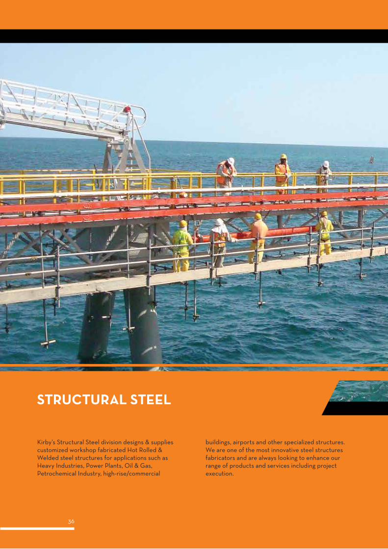
Kirby’s Structural Steel division designs & supplies customized workshop fabricated Hot Rolled & Welded steel structures for applications such as Heavy Industries, Power Plants, Oil & Gas, Petrochemical Industry, high-rise/commercial
buildings, airports and other specialized structures. We are one of the most innovative steel structures fabricators and are always looking to enhance our range of products and services including project execution.
37
EngineeringThe engineering department uses the latest versions of internationally renowned industry standard 2D and 3D software for designing and detailing. Kirby upholds its position at the cutting edge of the industry due to its commitment to quality and customer satisfaction. Skilled structural engineers using the very latest in computerized engineering design and detailing systems permit the selection of the most economical, accurate and efficient framing and cladding systems.
Design SoftwareThe Design / Engineering Department are fully computerized, utilizing the latest software packages to enable them to produce the most economical structures in the shortest time possible. The software packages most frequently used are: STAAD PRO, PROKON, AUTO CAD, BOCAD, and XSTEEL.
Industrial Infrastructure Commercial BuildingsSteel plantsOil & Gas StructuresMetal SmeltersChemical Plants Fertilizers and PetrochemCement Plants etc.
Power PlantsAirportsRoad & Railway BridgesTransmission TowersTelecom Towers etc.
High Rise BuildingsCommercial ComplexesMalls & Multiplexes etc.
38
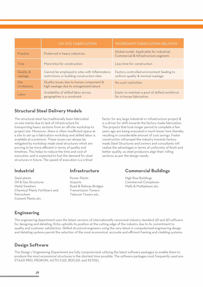
Structural Steel Delivery Models
The structural steel has traditionally been fabricated on-site mainly due to lack of infrastructure for transporting heavy sections from an off-site workshop to project site. Moreover, there is often insufficient space at a site to set up a fabrication workshop and skilled labor is available at a premium. These issues can always be mitigated by workshop made steel structures which are proving to be more efficient in terms of quality and timelines. This helps to reduce the time and cost of execution, and is expected to fuel the demand for steel structures in future. The speed of execution is a critical
factor for any large industrial or infrastructure project & is a driver for shift towards the factory made fabrication. The projects that took longer period to complete a few years ago are being executed in much lesser time thereby resulting in considerable amount of cost savings. Faster construction will propel the industry towards factory made Steel Structures and owners and consultants will realize the advantages in terms of uniformity of finish and better quality, as steel producers align their rolling sections as per the design needs.
ON SITE FABRICATION WORKSHOP FABRICATION DELIVERY
Cannot be employed in sites with Inflammatory restrictions or building construction sites
Preferred in heavy industries
More time for construction
Availability of skilled labor across geographies is a constraint
Quality issues due to human component & high wastage due to unorganized nature
Practice
Time
Labor
Quality & wastage
Site Limitations
Less time for construction
Global model. Applicable for industrial, Commercial & Infrastructure segment.
Factory controlled environment leading to uniform quality & minimal wastage
No such restriction
Easier to maintain a pool of skilled workforce for in-house fabrication
39
Non Destructive Testing
WeldingAll welding operations are carried out in accordance with Kirby Steel Engineering’s approved welding procedures by independently qualified welders. Kirby welders are trained to perform the welding processes SAW, SMAW & FCAW and are AWS D1.1 qualified for various positions including 6GR for T, K, and Y connections. During the welding operation all welders are continually monitored to ensure that the welding parameters, as detailed in the relevant procedure, are adhered to and that the level of workmanship is maintained.
All items, after completion of welding are visually inspected against the requirements of AWS D 1.1 for compliance. Any visual discontinuity is marked and repaired immediately. Only when the item has been fully passed and accepted will it be released to blasting and painting all welding inspections are entered onto the piece monitoring system.
Welding Inspection & Non-Destructive Testing monitoring of welding variables like voltage, amperage and welding consumables is carried out per approved welding procedure specifications. In addition, visual inspection is carried out on 100% of each section to ensure highest quality in manufacturing
Kirby is capable of performing UT, MPI & PT as per AWS D1.1/D1.1M-2006 requirements. Further, Kirby has the capability to carry out ultrasonic, radiography, MPI & PT if required the results of all NDT examinations are entered on the Piece Monitoring System.
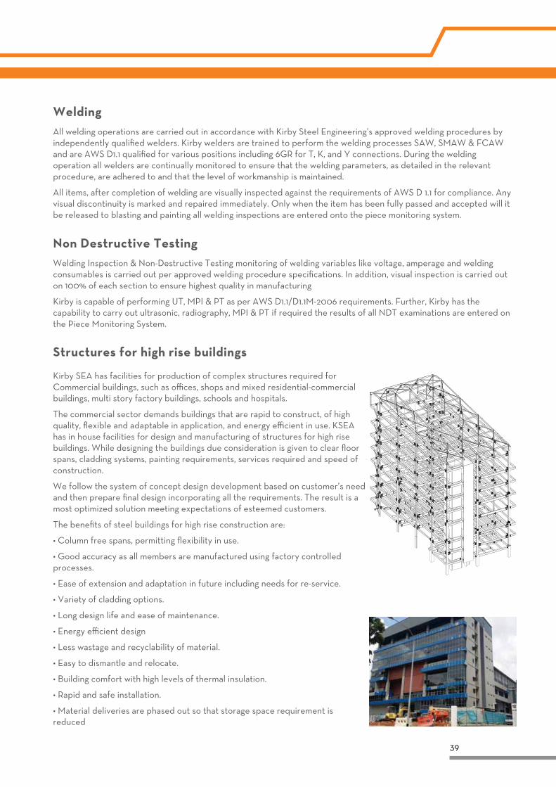
Structures for high rise buildings
Kirby SEA has facilities for production of complex structures required for Commercial buildings, such as offices, shops and mixed residential-commercial buildings, multi story factory buildings, schools and hospitals.
The commercial sector demands buildings that are rapid to construct, of high quality, flexible and adaptable in application, and energy efficient in use. KSEA has in house facilities for design and manufacturing of structures for high rise buildings. While designing the buildings due consideration is given to clear floor spans, cladding systems, painting requirements, services required and speed of construction.
We follow the system of concept design development based on customer’s need and then prepare final design incorporating all the requirements. The result is a most optimized solution meeting expectations of esteemed customers.
The benefits of steel buildings for high rise construction are:
• Column free spans, permitting flexibility in use.
• Good accuracy as all members are manufactured using factory controlled processes.
• Ease of extension and adaptation in future including needs for re-service.
• Variety of cladding options.
• Long design life and ease of maintenance.
• Energy efficient design
• Less wastage and recyclability of material.
• Easy to dismantle and relocate.
• Building comfort with high levels of thermal insulation.
• Rapid and safe installation.
• Material deliveries are phased out so that storage space requirement is reduced
40
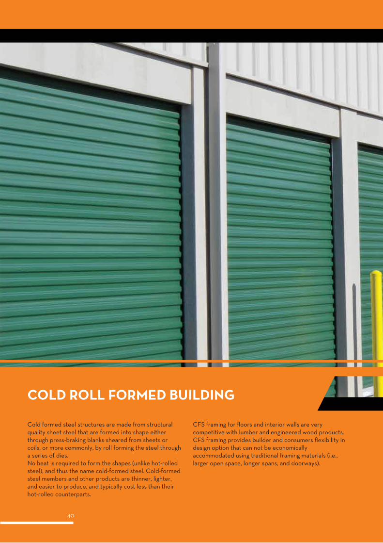
COLD ROLL FORMED BUILDING
Cold formed steel structures are made from structural quality sheet steel that are formed into shape either through press-braking blanks sheared from sheets or coils, or more commonly, by roll forming the steel through a series of dies.No heat is required to form the shapes (unlike hot-rolled steel), and thus the name cold-formed steel. Cold-formed steel members and other products are thinner, lighter, and easier to produce, and typically cost less than their hot-rolled counterparts.
CFS framing for floors and interior walls are very competitive with lumber and engineered wood products. CFS framing provides builder and consumers flexibility in design option that can not be economically accommodated using traditional framing materials (i.e., larger open space, longer spans, and doorways).
41
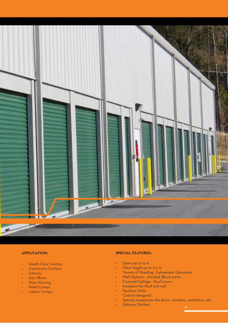
• Health Care Centres• Community Centers• Schools• Site offices• Mass Housing• Relief Camps• Labour Camps
APPLICATION:
• Spans up to 15 m• Clear height up to 3.0 m• Variety of Sheeting : Galvanized, Galvalume• Wall Options – sheeted, Block works• Covered Ceilings – Roof Liners• Insulation for Roof and wall• Partition Walls• Custom-designed• Special accessories like doors, windows, ventilators, etc.• Defence Shelters
SPECIAL FEATURES:
42
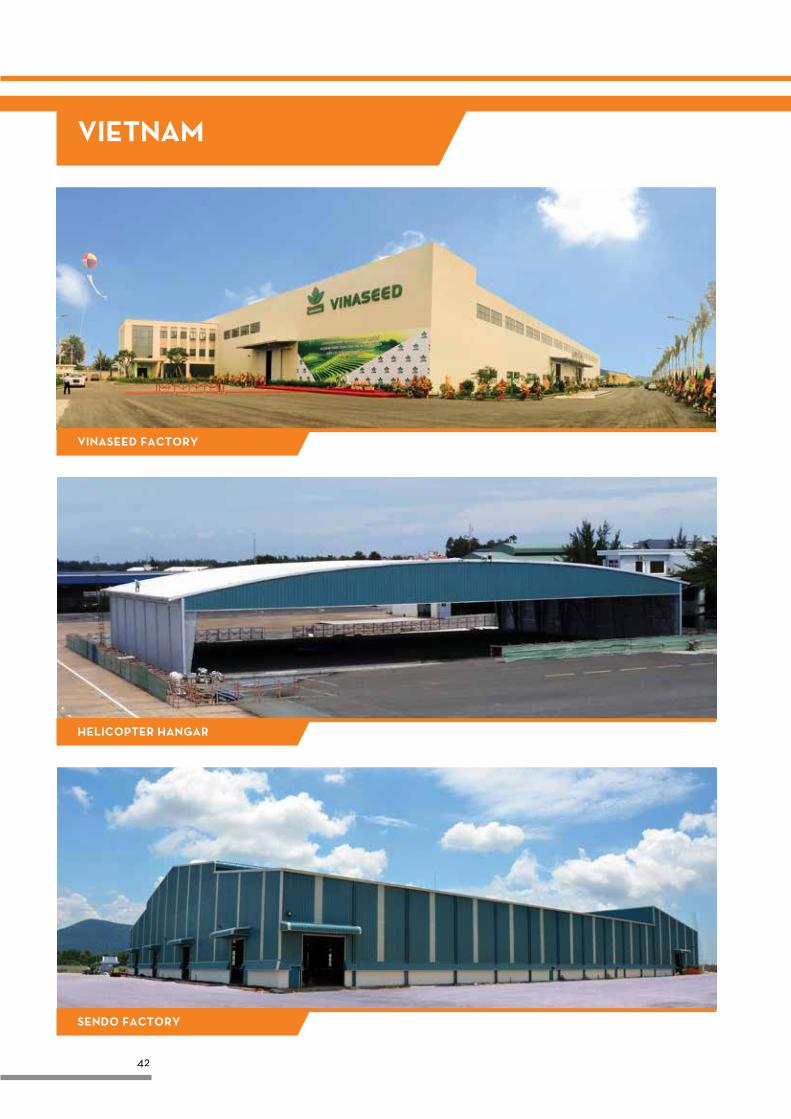
VIETNAM
VINASEED FACTORY
HELICOPTER HANGAR
SENDO FACTORY
43
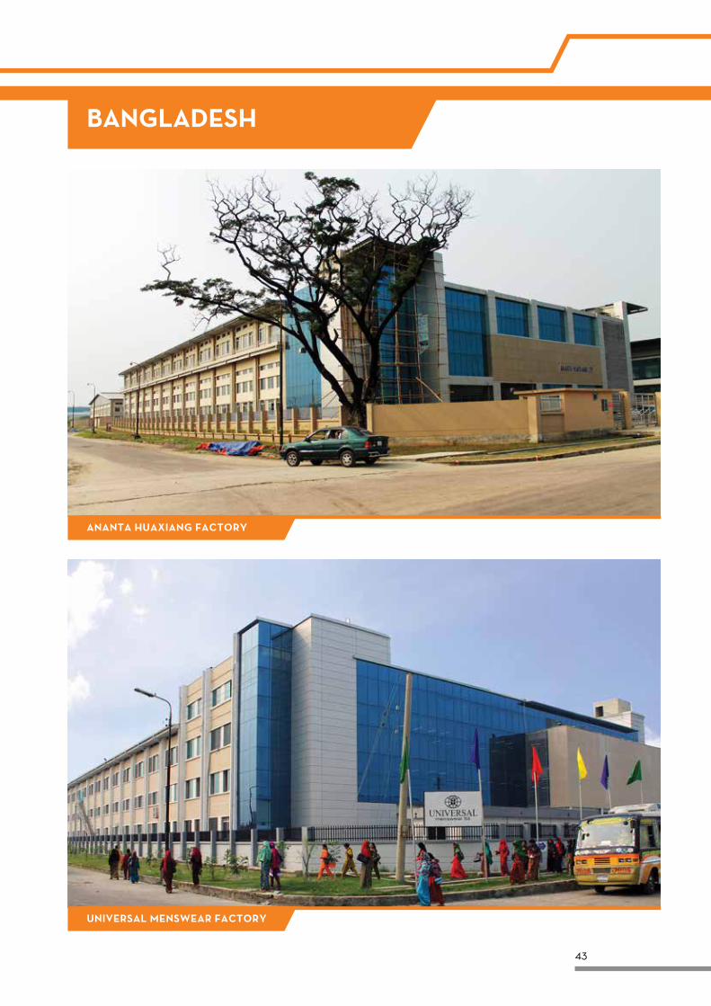
ANANTA HUAXIANG FACTORY
UNIVERSAL MENSWEAR FACTORY
BANGLADESH
44
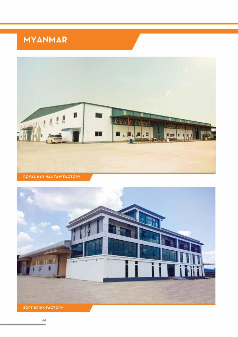
MYANMAR
SOFT DRINK FACTORY
ROYAL NAY NAL TAW FACTORY
45
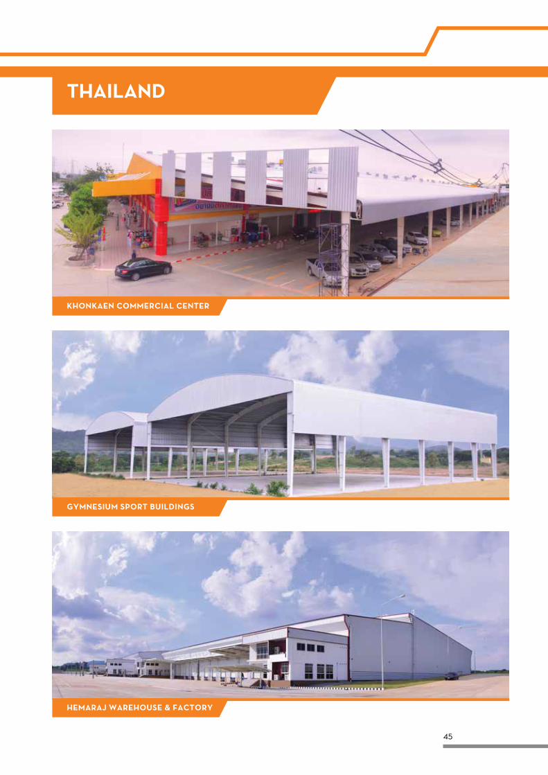
THAILAND
KHONKAEN COMMERCIAL CENTER
GYMNESIUM SPORT BUILDINGS
HEMARAJ WAREHOUSE & FACTORY
46
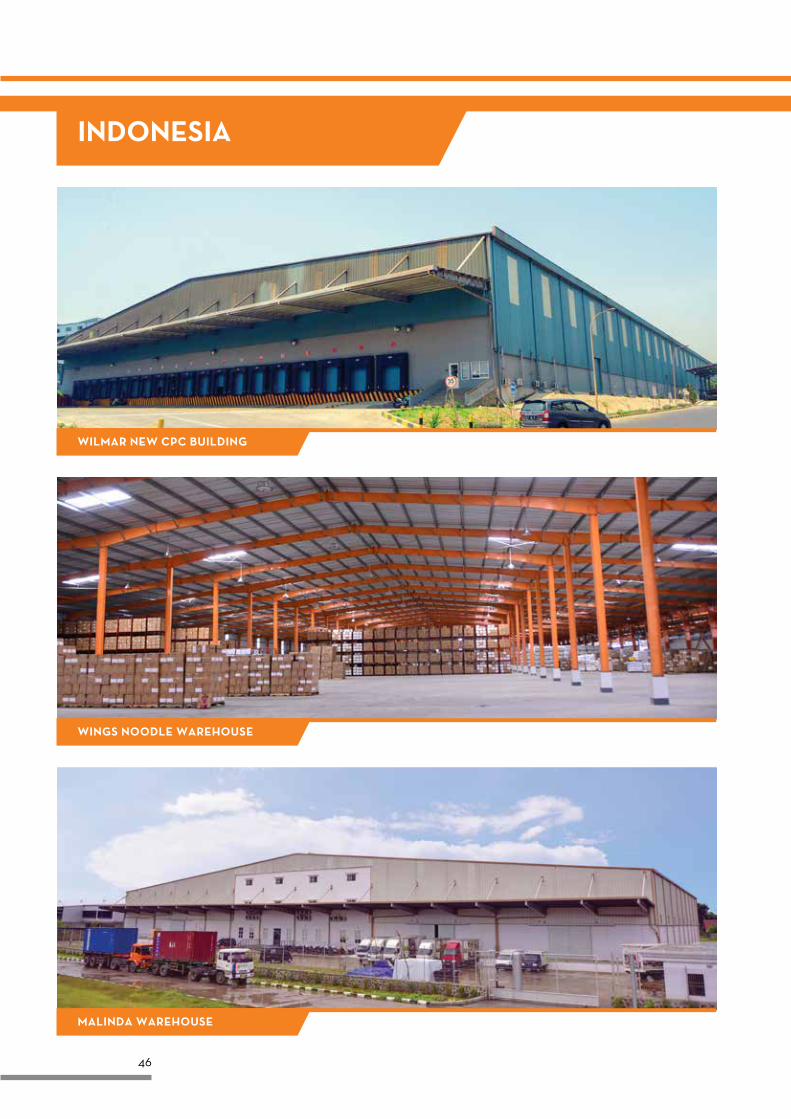
INDONESIA
WILMAR NEW CPC BUILDING
WINGS NOODLE WAREHOUSE
MALINDA WAREHOUSE
47
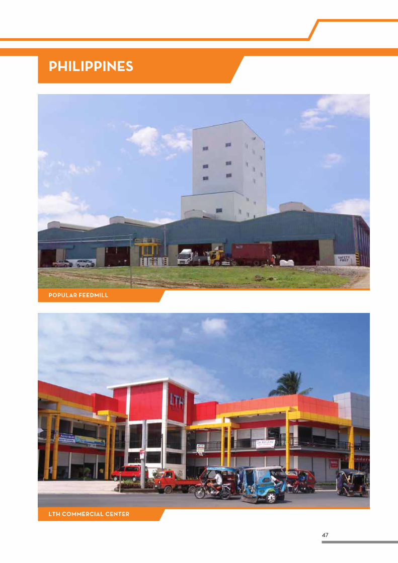
POPULAR FEEDMILL
LTH COMMERCIAL CENTER
PHILIPPINES
48
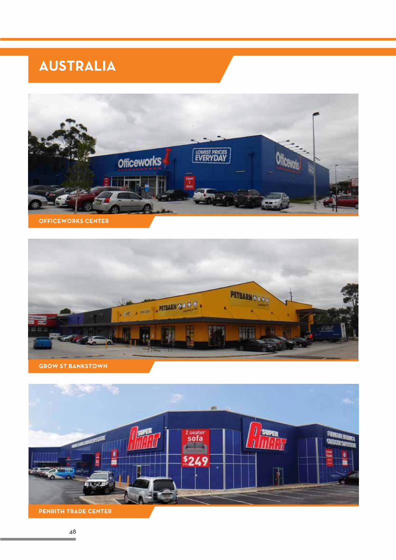
AUSTRALIA
OFFICEWORKS CENTER
GROW ST BANKSTOWN
PENRITH TRADE CENTER
49
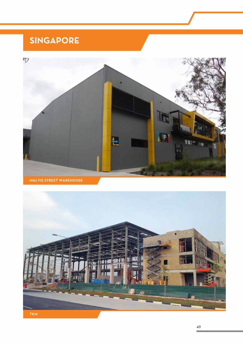
SINGAPORE
MALVIS STREET WAREHOUSE
TKM
50
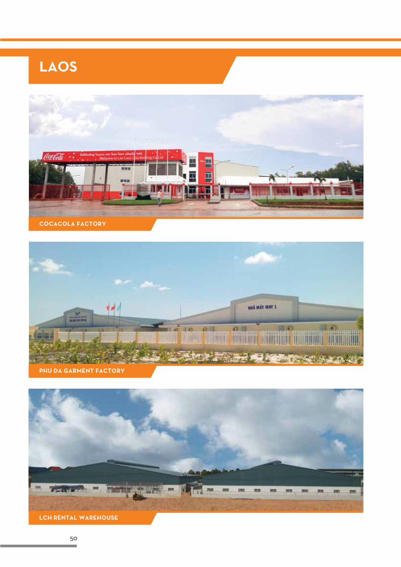
LAOS
COCACOLA FACTORY
PHU DA GARMENT FACTORY
LCH RENTAL WAREHOUSE
51
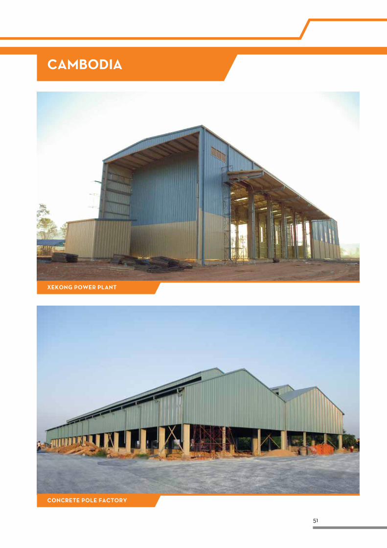
CAMBODIA
XEKONG POWER PLANT
CONCRETE POLE FACTORY

Middle East & Africa Corporate Office & Kuwait Plant
Kirby Building Systems - Kuwait Mina Abdullah Industrial Area P.O. Box 23933 Safat, 13100, Kuwait
Tel.: +965 2326 2800 Fax: +965 2326 1793 / 8 Email: [email protected]
Ras Al Khaimah Manufacturing Plant, UAE
Kirby Building Systems - UAE LLC, Al Jazeera Industrial Area II, Behind RAK Ceramics, PO Box No. 6624, Ras Al Khaimah, UAE.
Tel.: +971 7204 3333 Fax: +971 7244 7830 Email: [email protected]
India Corporate Office & Hyderabad Plant
Kirby Building Systems India Ltd. Plot No 8-15, IDA Phase III, Pashamylaram, Medak Dist. - 502 307 Telangana, India
Tel.: +91 8455 224401 / 02 / 03 / 04 Fax: +91 8455 224419 / 27 Email: [email protected]
Haridwar Plant, India
Kirby Building Systems India (Uttaranchal) Pvt. Ltd. Plot No 2, Sector 11, Integrated Industrial Estate, Haridwar, Uttarakhand - 249403, India
Tel: +91 1334 235317, 235318, 235319 Fax: +91 1334 235314, 235397 Email: [email protected]
South East Asia Corporate Office & Vietnam Plant
Kirby South East Asia Co., Ltd. 7th Floor, Phuoc Thanh Building, 199 Dien Bien Phu, Ward 15, Binh Thanh District, Hochiminh City, Vietnam
Tel.: +84 5422 1155 Fax: +84 5422 1156 Email: [email protected]
Kirby is a wholly owned subsidiary of Alghanim Industries
Alghanim Industries, P.O. Box 223, Safat, Kuwait 13003
www.kirbyinternational.com
Follow us at