product bulletin mark 6 - petrik naval
TRANSCRIPT
V A F I N S T R U M E N T S T O B E R E A L L Y S U R E
Oilcon® Mark 6Oil Discharge Monitoring & Control Systems
1
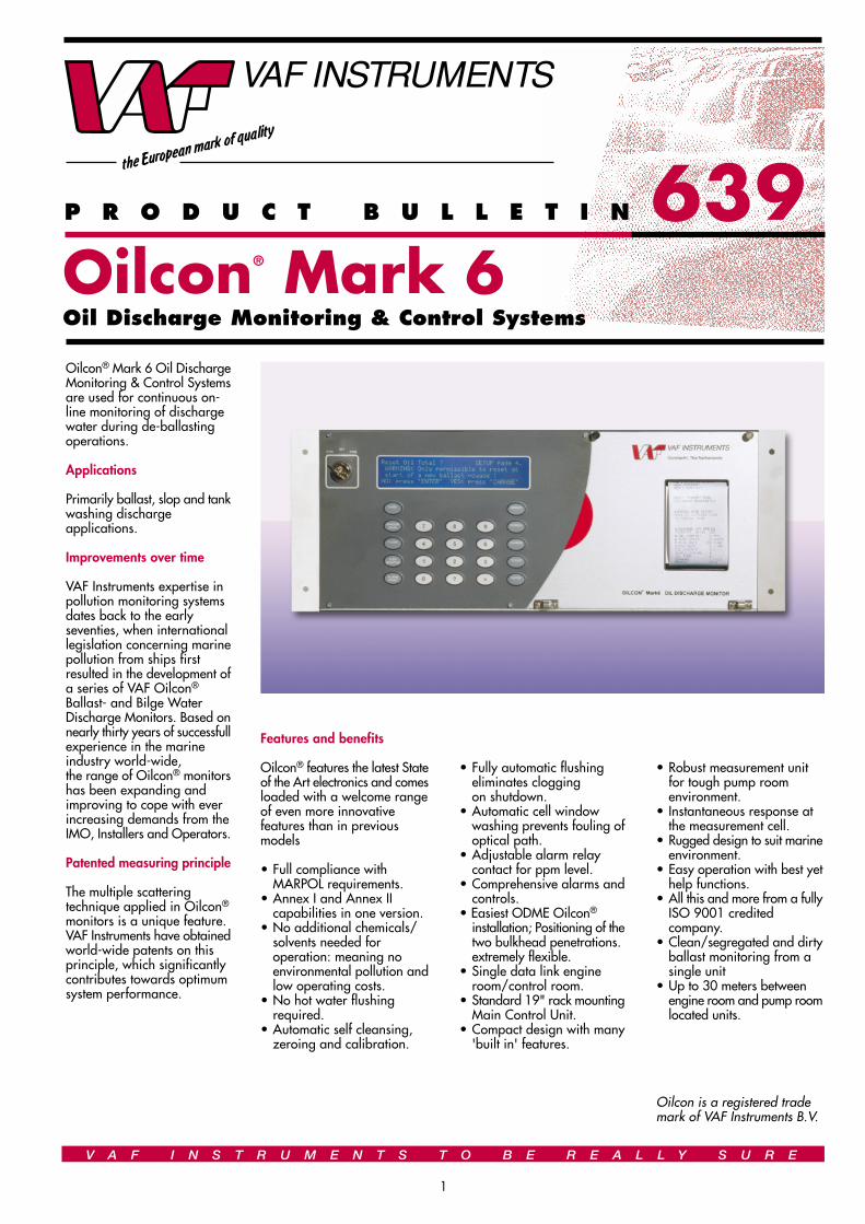
Oilcon® Mark 6 Oil DischargeMonitoring & Control Systemsare used for continuous on-line monitoring of dischargewater during de-ballastingoperations.
Applications
Primarily ballast, slop and tankwashing dischargeapplications.
Improvements over time
VAF Instruments expertise inpollution monitoring systemsdates back to the earlyseventies, when internationallegislation concerning marinepollution from ships firstresulted in the development ofa series of VAF Oilcon®
Ballast- and Bilge WaterDischarge Monitors. Based onnearly thirty years of successfullexperience in the marineindustry world-wide,the range of Oilcon® monitorshas been expanding andimproving to cope with everincreasing demands from theIMO, Installers and Operators.
Patented measuring principle
The multiple scatteringtechnique applied in Oilcon®
monitors is a unique feature.VAF Instruments have obtainedworld-wide patents on thisprinciple, which significantlycontributes towards optimumsystem performance.
Features and benefits
Oilcon® features the latest Stateof the Art electronics and comesloaded with a welcome rangeof even more innovativefeatures than in previousmodels
• Full compliance with MARPOL requirements.
• Annex I and Annex II capabilities in one version.
• No additional chemicals/solvents needed for operation: meaning no environmental pollution andlow operating costs.
• No hot water flushing required.
• Automatic self cleansing, zeroing and calibration.
• Robust measurement unitfor tough pump room environment.
• Instantaneous response at the measurement cell.
• Rugged design to suit marineenvironment.
• Easy operation with best yethelp functions.
• All this and more from a fullyISO 9001 credited company.
• Clean/segregated and dirtyballast monitoring from a single unit
• Up to 30 meters between engine room and pump roomlocated units.
Oilcon is a registered trademark of VAF Instruments B.V.
• Fully automatic flushing eliminates cloggingon shutdown.
• Automatic cell window washing prevents fouling ofoptical path.
• Adjustable alarm relay contact for ppm level.
• Comprehensive alarms andcontrols.
• Easiest ODME Oilcon® installation; Positioning of thetwo bulkhead penetrations. extremely flexible.
• Single data link engine room/control room.
• Standard 19" rack mountingMain Control Unit.
• Compact design with many'built in' features.
P R O D U C T B U L L E T I N 639

Pressureregulatingvalve
Skid (6)
Sample valve
DP/Itransmitter (4)
Fresh water supply
PUMP ROOMENGINE ROOM
PUMP ROOMENGINE ROOM
Sampling pump (7)
Starter box (3)
MTC
Electricopneumaticunit (2)
Main control unit (1)
V A F I N S T R U M E N T S T O B E R E A L L Y S U R E
2
CONTROL ROOM
HAZARDOUS SAFE AREA
Fromcargo pump
Fromstripping pump
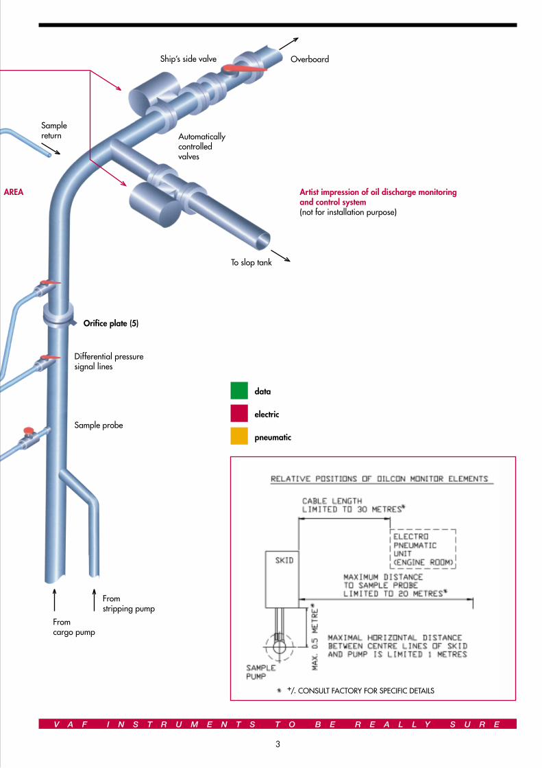
Sample probe
Differential pressuresignal lines
Orifice plate (5)
To slop tank
Automaticallycontrolledvalves
Ship’s side valve Overboard
V A F I N S T R U M E N T S T O B E R E A L L Y S U R E
3
Artist impression of oil discharge monitoringand control system(not for installation purpose)
AREA
data
electric
pneumatic
Samplereturn
+/- CONSULT FACTORY FOR SPECIFIC DETAILS
V A F I N S T R U M E N T S T O B E R E A L L Y S U R E
4
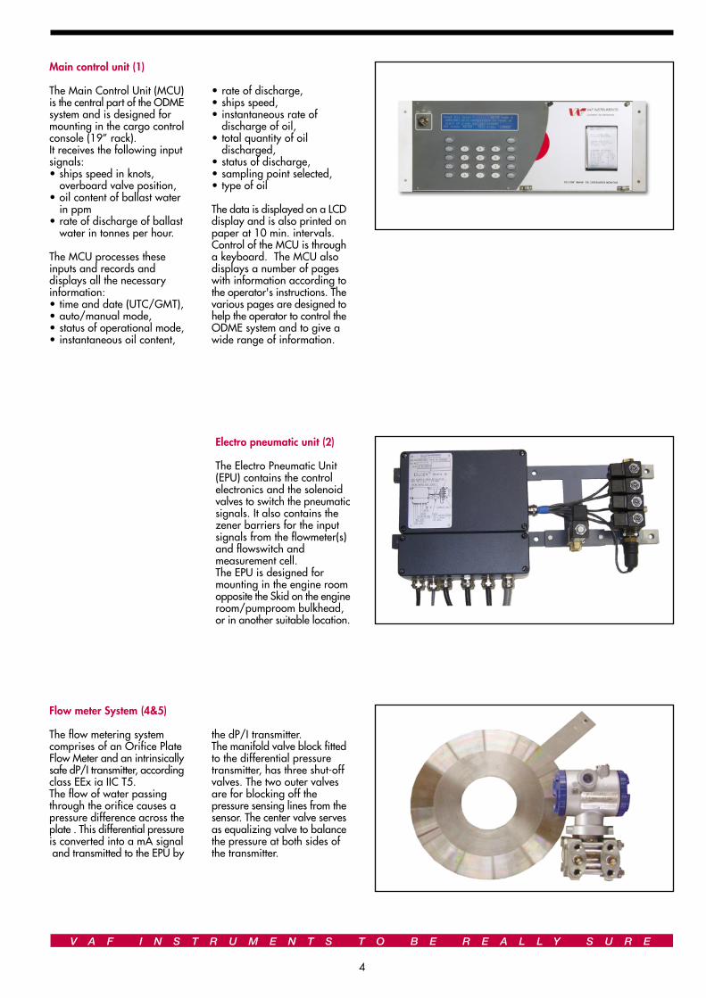
Main control unit (1)
The Main Control Unit (MCU)is the central part of the ODMEsystem and is designed formounting in the cargo controlconsole (19” rack).It receives the following inputsignals:• ships speed in knots,
overboard valve position,• oil content of ballast water
in ppm• rate of discharge of ballast
water in tonnes per hour.
The MCU processes theseinputs and records anddisplays all the necessaryinformation:• time and date (UTC/GMT),• auto/manual mode,• status of operational mode,• instantaneous oil content,
• rate of discharge,• ships speed,• instantaneous rate of
discharge of oil,• total quantity of oil
discharged,• status of discharge,• sampling point selected,• type of oil
The data is displayed on a LCDdisplay and is also printed onpaper at 10 min. intervals.Control of the MCU is througha keyboard. The MCU alsodisplays a number of pageswith information according tothe operator's instructions. Thevarious pages are designed tohelp the operator to control theODME system and to give awide range of information.
Flow meter System (4&5)
The flow metering systemcomprises of an Orifice PlateFlow Meter and an intrinsicallysafe dP/I transmitter, accordingclass EEx ia IIC T5.The flow of water passingthrough the orifice causes apressure difference across theplate . This differential pressureis converted into a mA signal and transmitted to the EPU by
Electro pneumatic unit (2)
The Electro Pneumatic Unit(EPU) contains the controlelectronics and the solenoidvalves to switch the pneumaticsignals. It also contains thezener barriers for the inputsignals from the flowmeter(s)and flowswitch andmeasurement cell.The EPU is designed formounting in the engine roomopposite the Skid on the engineroom/pumproom bulkhead,or in another suitable location.
the dP/I transmitter.The manifold valve block fittedto the differential pressuretransmitter, has three shut-offvalves. The two outer valvesare for blocking off thepressure sensing lines from thesensor. The center valve servesas equalizing valve to balancethe pressure at both sides ofthe transmitter.

V A F I N S T R U M E N T S T O B E R E A L L Y S U R E
5
Skid Assembly (6)
The Skid Assembly contains the necessary itemsto handle the sampled ballast water to measurethe oil content. In the Skid Assembly is apneumatically operated shuttle valve and windowwash pump.The shuttle valve selects between fresh waterforward or backward flush and sample.Also contained in the Skid Assembly is thedetector cell which contains the revolutionaryelectronic sensing system used to determine oilcontent.The Skid Assembly is normally mounted in thepumproom opposite the EPU on the engine roomside of the bulkhead.
Pump/Motor Assembly (7)
The Pump/Motor Assembly comprises a high-shear vortex pump, a certified gas tight bulkheadseal and a motor. The pump provides a degreeof sample water conditioning as the shearingeffect tends to produce droplets of oil of roughlysimilar size. The motor is suitable for 440 Vat 60 Hz, runs at 3460 rpm respectively andis constructed to IP55 and isolation Class F,IEC 34-1.
Details of principal components of Mark 6Oilcon® oil discharge monitoring & controlsystem
5 Orifice PlateThickness: 6 mmMaterial: Stainless SteelDiameter and bore: Specific to eachinstallation
6 SkidWeight: 17 kgDimensions: 500W x 420H x 177DAir Connections: 6 mm & 10 mm tubeWater connections:15 mm OD Tube
7 Sampling pumpWeight: 30 kgLength overall: 348Cut out diameter: 290Connections: 15mm OD tube
1 Main Control UnitWeight: 3,5 kgDimensions: 483W x 174H x 111D
2 Electro Pneumatic UnitWeight: 7,5 kgDimensions: 500W x 263H x 114D
3 Motor Starter box
4 Electronic Differential PressureTransmitterWeight: 5 kgDimensions: 225W x 195H x 194D

V A F I N S T R U M E N T S T O B E R E A L L Y S U R E
6
Technical specification
Range : 0 - 1000 ppmAccuracy : in accordance with IMO Resolution A.586 (14),
the system reponse is within theaccuracy specified.
Response time : less than 10 secondsSample flow rate : between 450 and 550 l/hZero noise and drift : less than 2 ppm and nil when changing
from fresh water to sea waterResponse to oils : in accordance with IMO specificationsSensitivity to solids : in accordance with IMO Resolution
A.586 (14) accuracy limits.Fouling : clears in less than one minute after
IMO fouling test.Water temperature range : 5˚C - 65˚CMax amb temp: : 55˚CAlarm setting : Adjustable over full range.Alarm outputs : no/nc contact, (2A at 220 VAC max)Electrical supplies : 115/230 VAC 1 phase 50/60 Hz,
380-460 VAC, 3 phase 50/60 HzAir supply : 4.. 7 bar, dry clean airSample points : Optional up to 6 sample pointsValve control : Dirty ballast relays on MCU
: Clean/segregated ballast relays on MCU
Principle of operation
The measurement techniqueused in the Oilcon® OilDischarge Monitor is based onscattered light. In accordancewith IMO ResolutionA586(14), the Mark 6 Oilcon®
is able to descriminate betweenoil and other contaminantssuch as mud, rust or entrainedair.
A sample of discharge waterpasses through a detector cellwhile light enters and leavesthe measurement area of thecell. The sample flow is at rightangles to the optical path.When no particles or oildroplets are present in thewater, light can pass straightthrough the cell (Direct beam).When oil is present in the formof a homogeneous mixture,light is scattered at differentangles (Scatter beam). Theintensity of scattered light at aspecific angle depends on thedensity of oil droplets and upontheir particle size relative tothe wavelenght of radiation.The intensity of light of thedirect beam decreaseslogarithmically with increasingoil concentration, while thescatter beam increases linearybut passes through a maximumbefore decreasinglogarithmically.
The light source used in theOilcon® Oil Discharge Monitoris a near infra red diode whichis operated in the pulsed modeso that the average powerdissipation is low, although theintensity is high. The light signalis processed and transmittedalong a communication cablefrom the detector cell to theEPU, where the detectionsignals are used to computethe oil levels present in thesample passing through thedetector cell.
Automatic sequential controlof forward and backwardflushing at start up and shutdown of the monitor preventserroneous readings and keepsthe sampling lines clean. Thisalso ensures reliable start up,minimises system deteriorationand ensures that the pipeworkis left in clean condition priorto the next use of the monitor.At the end of the start upflushing cycle a system zerocheck is performed, thisautomatic zero settingcompensates for any smalldeposits on the cell windows.The window wash pump cleansthe cell windows at regularintervals during operation.
V A F I N S T R U M E N T S T O B E R E A L L Y S U R E
7
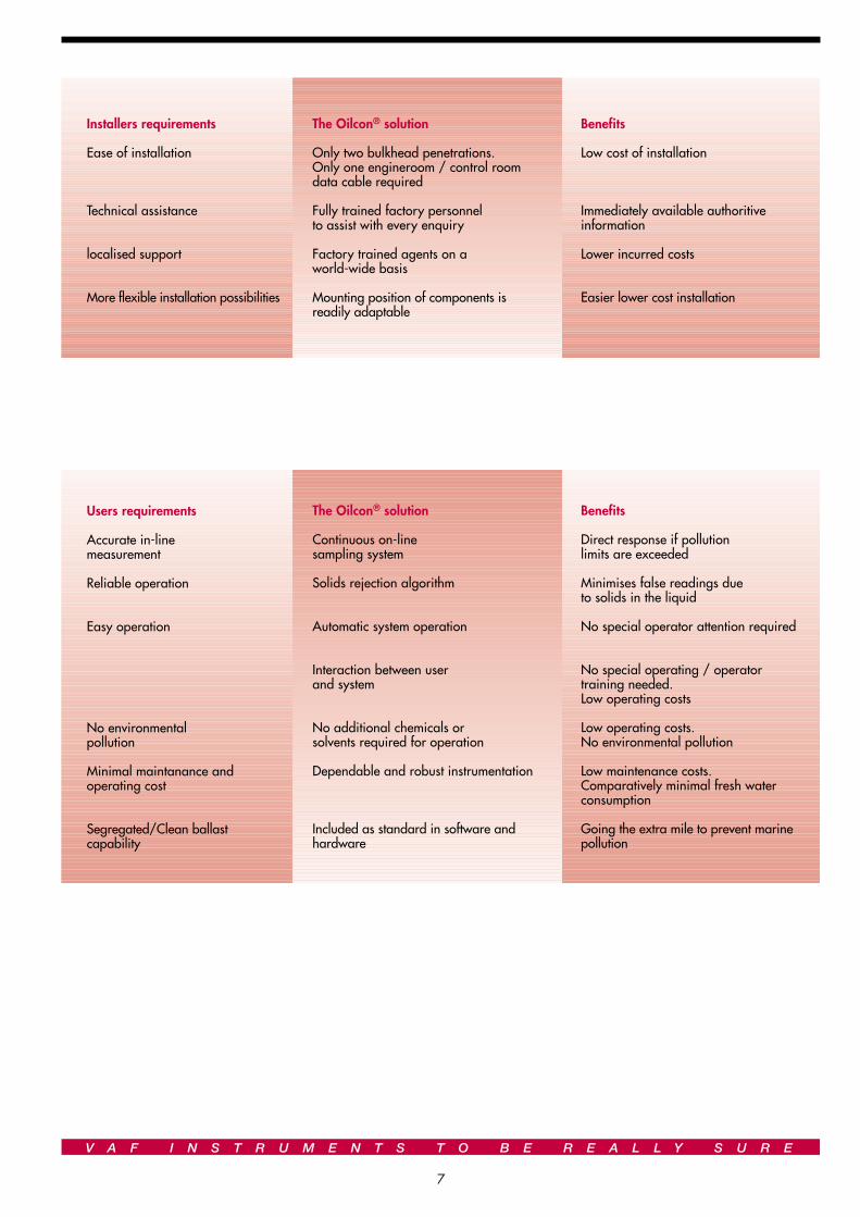
Installers requirements
Ease of installation
Technical assistance
localised support
More flexible installation possibilities
The Oilcon® solution
Only two bulkhead penetrations.Only one engineroom / control roomdata cable required
Fully trained factory personnelto assist with every enquiry
Factory trained agents on aworld-wide basis
Mounting position of components isreadily adaptable
Benefits
Low cost of installation
Immediately available authoritiveinformation
Lower incurred costs
Easier lower cost installation
Users requirements
Accurate in-linemeasurement
Reliable operation
Easy operation
No environmentalpollution
Minimal maintanance andoperating cost
Segregated/Clean ballastcapability
The Oilcon® solution
Continuous on-linesampling system
Solids rejection algorithm
Automatic system operation
Interaction between userand system
No additional chemicals orsolvents required for operation
Dependable and robust instrumentation
Included as standard in software andhardware
Benefits
Direct response if pollutionlimits are exceeded
Minimises false readings dueto solids in the liquid
No special operator attention required
No special operating / operatortraining needed.Low operating costs
Low operating costs.No environmental pollution
Low maintenance costs.Comparatively minimal fresh waterconsumption
Going the extra mile to prevent marinepollution
VAF Instruments B.V.Vierlinghstraat 24, NL-3316 EL DordrechtP.O.Box 40, NL-3300 AA DordrechtThe NetherlandsTelephone: +31 78 618 3100Fax: +31 78 617 7068Internet: www.vaf.nlE-mail: [email protected]
Represented by:
All
copy
right
s re
serv
edPu
bl. N
o. 3
69-G
B-02
03
ISO-9001 REGISTERED FIRMDNV Certification B.V., THE NETHERLANDS
Accreditedby the RvA
V A F I N S T R U M E N T S T O B E R E A L L Y S U R E
8
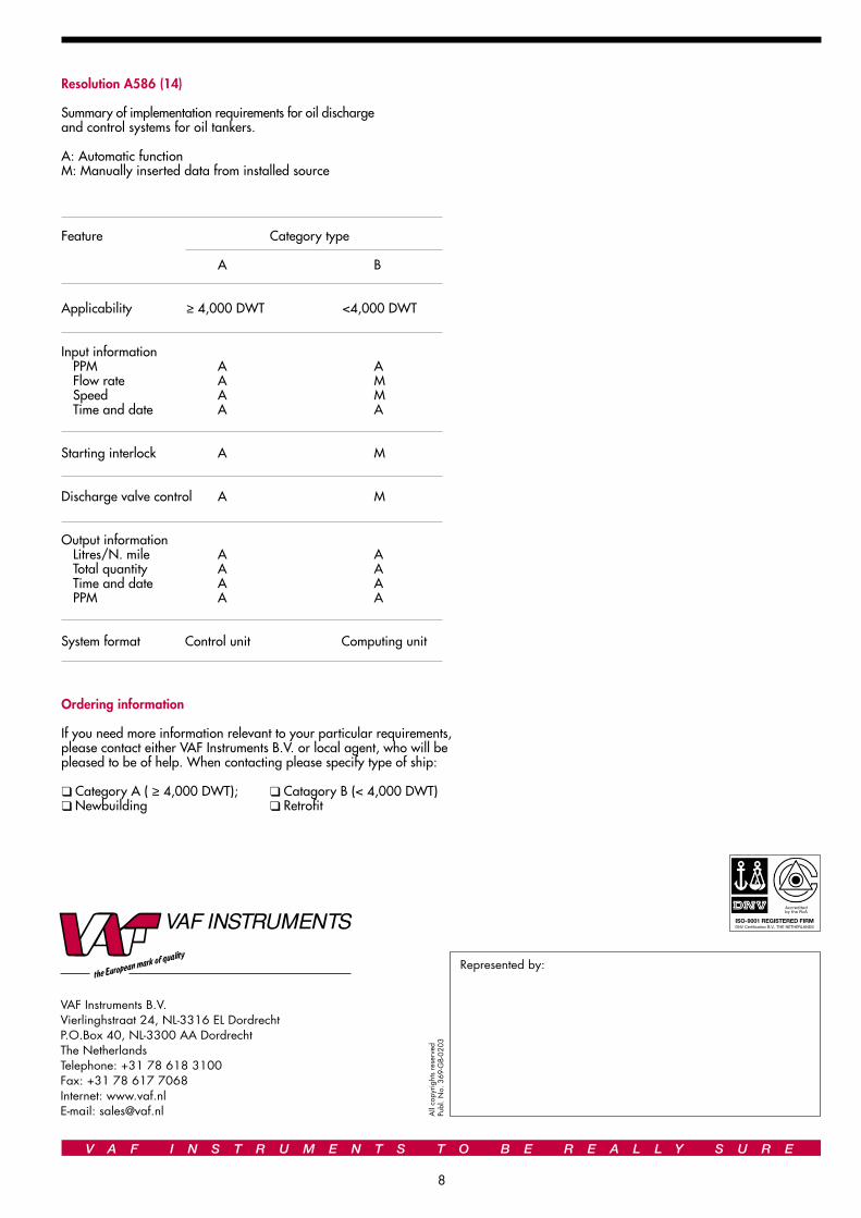
Resolution A586 (14)
Summary of implementation requirements for oil dischargeand control systems for oil tankers.
A: Automatic functionM: Manually inserted data from installed source
Ordering information
If you need more information relevant to your particular requirements,please contact either VAF Instruments B.V. or local agent, who will bepleased to be of help. When contacting please specify type of ship:
❑ Category A ( ≥ 4,000 DWT); ❑ Catagory B (< 4,000 DWT)❑ Newbuilding ❑ Retrofit
Feature Category type
A B
Applicability ≥ 4,000 DWT <4,000 DWT
Input informationPPM A AFlow rate A MSpeed A MTime and date A A
Starting interlock A M
Discharge valve control A M
Output informationLitres/N. mile A ATotal quantity A ATime and date A APPM A A
System format Control unit Computing unit