product catalog 0511
TRANSCRIPT

CARRIER GRADE PERFORMANCE
UTILITY GRADE RELIABILITY
LOWEST TOTAL COST OF OWNERSHIP✓
✓
✓
Product Catalog

Our Company
RuggedCom designs and manufactures rugged communications equipment for harsh environments. Founded by people with strong backgrounds in electric utility and industrial automation, we at RuggedCom have a first hand understanding of the needs and issues faced by our customers. This is reflected in RuggedCom’s industry leadership in pioneering technologies and products which offered the world’s first IEC 61850-3 compliant Ethernet switch suitable for electric utility substation environments, the world’s first IEEE 1613 Class 2 error free communications devices, the world’s fastest network fault recovery, and the world’s first fully managed IP67 rated Ethernet switch. Other industry specific innovations have made our products the product of choice for high-reliability, high-availability, mission critical communications networks deployed in harsh environments around the world.
Our corporate headquarters are located in Concord, Ontario, Canada with regional offices worldwide. RuggedCom sales representatives and distributors can be found in over 25 countries around the world to provide knowledgeable and timely support.
Our Products
RuggedCom products provide a level of ruggedness and reliability that have set the standard for rugged communications networks deployed in harsh environments. RuggedCom products offer extreme temperature (-40°C to +85°C) immunity, IP67 rated ingress pollution protection allowing immersion in water, Zero-Packet-Loss™ technology for immunity to high levels of electromagnetic interference, and enhanced rapid spanning tree (eRSTP™) performance for ultra high-speed network fault recovery.
RuggedCom products can be found in mission critical networks used in: substation automation; smart, self-healing, power grids or “Smart Grid” systems; intelligent transportation systems for traffic management and railway control systems; and in process control and manufacturing automation systems used across multiple industrial sectors.
RuggedCom products are at their best when the environment around them is at its worst. Our faith in our product reliability is demonstrated by providing a standard 5 year warranty on all RuggedCom products.

RuggedCom Product Catalogue
RuggedRated™ for Reliabilityin Harsh Environments�� EMI Immunity per IEEE 1613 & IEC 61850-3�� Zero-packet-loss™ under EMI stress (KEMA tested)�� IEEE 1613 Class 2 performance (KEMA tested)�� Extended Temperature: -40 to 85°C(no fans)�� High reliability: MTBF > 1,000,000 hours�� High availability: >99.9999%�� Dual Redundant Power Supplies�� Integrated Cyber Security Features�� NERC CIP Precision Time Sync: <1μs�� Support for Protection & Control applications�� Support for: AMI, DA, DMS, EMS, SCADA & IT�� Exceeds NEMA TS 2�� Long Haul Fiber Support�� Fast Network Fault Recovery (<5ms with eRSTP™)�� Integrated Power Supplies (Optional Dual Redundancy)�� Advanced Layer 2/3 Networking�� IP66 / 67 Rated Products (Waterproof/Dustproof)�� High EMI Immunity exceeds IEC 61000-6-2 and IEC 61800-3�� Heavy Duty Construction Resilient to Vibrations and Shock�� IDS capability�� Integrated Router/Firewall/VPN�� Stateful Firewall with NAT�� Full IPSEC Virtual Private Networking
RuggedCom Precision Time Solution�� IEEE 1588 version 2 precision timing�� IEEE 1588 to IRIG-B conversion�� GPS clock input supporting Grandmaster Clock mode�� Transparent Clock Mode and Multiple clock source inputs
www.RuggedCom.com 3
Software
OpenHouse
R
ConsultingHighly Skilled ConsultantsNetwork Design & Implementation
TrainingProfessional TrainersFull Set of Training Courses
Support24x7x365 Technical Action CenterHighly Skilled Multilingual Customer Support
Professional Services

4
Utility Grade Products for the Substation EnvironmentRuggedCom has the Industry’s most complete basket of Ethernet networking devices designed specifically for the substation environment. Trends in electric utility automation, specifically substation automation, have converged upon a common communications architecture with the goal of having interoperability between a variety of Intelligent Electronic Devices found in the substation. The resulting standard that emerged is known as the Utility Communications Architecture 2.0 (UCA2.0) and is now becoming an international standard as IEC 61850.
The following network architecture illustrates the range of products available in the context of an IEC 61850 substation. Other network architecture such as ring or star topologies, or a hybrid topology, are also easily accommodated.
Intelligent Transportation SystemsRuggedCom offers a variety of rugged communications solutions for the transportation industry. Our products are used in:
�� Intelligent Transportation Systems (ITS) for projects implementing Advanced Traffic Management Systems in accordance with NTCIP requiring C2F and C2C communications.�� Rail applications utilizing EN 50121-4 compliant Ethernet networks installed in wayside cabinets for control, signaling and video monitoring applications.�� Center-to-field (C2F) Communications: A traffic signal management system communicating with traffic signal controllers at intersections, monitoring devices, passenger information signs on transit vehicles, transit stations and stops.�� Center-to-Center (C2C) Communications: Two or more traffic signal management systems exchanging information to achieve coordinated operation of traffic signals managed by the different systems and to enable personnel at one center to monitor the status of signals operated from another center.
C
B
A
Power System
SCADA WAN
RuggedRouter™Cyber Security Appliance
52
RuggedServer™Serial Device Servers
RuggedMC™Media Converters
RuggedSwitch™Ethernet Switches
Merging Unit(s)
IED = Intelligent Electronic Device
RuggedSwitch™Ethernet Switches
NERC CIP Cyber Security
IEC 61850-8-1Station Bus
IEC 61850-9-2Process Bus
Ethernet SwitchRuggedSwitch™ - RS900
Ethernet SwitchRuggedSwitch™ - RSG2100
Ethernet SwitchRuggedSwitch™ - RS900
Serial Device ServerRuggedServer™ - RS400
100/1000 MbpsFault Tolerant Fiber Optical
Ethernet Ring
Electric Power Transportation

5www.RuggedCom.com
Applications
Cyber Security FeaturesRuggedCom has the most complete line of substation hardened communication devices with built in cyber security features necessary to comply with the North American Electric Reliability Council (NERC) Critical Infrastructure Protection (CIP) requirements.
RuggedCom has been monitoring the developments of the various industry specific security standards including NERC CIP, ISA S99, AGA 12, IEC 62443, ISO 17799:2005 and PCSRF SPP-ICS, to ensure all RuggedCom products contain features necessary to comply with the identified requirements. By combining the security features the RuggedSwitch® products with that of the RuggedRouter® SCADA cyber security appliance, our customers establish an electronic security perimeter around their critical infrastructure preventing the disruption of mission critical applications by accidental or malicious acts.
Industrial Ethernet SolutionsIndustrial Ethernet on the plant floor has gained mass acceptance across multiple industries. Designed to create a real-time seamless flow of information between the plant floor and the back office, Industrial Ethernet networks are also becoming an integral part of real-time control systems for process control and discrete manufacturing applications.
Originally designed to be used in mission critical applications, RuggedCom’s substation hardened Ethernet Switches offer the industry’s highest levels of:
�� Reliability – MTBF > 500,000 Hrs�� Ruggedness – Operating Temperature (-40°C to +85°C)�� Immunity – Zero-Packet-Loss™ technology for high EMI environments.�� Performance – Gigabit performance with eRSTP™ for ultra high speed (5ms/hop) �� network fault recovery.�� Security – IEEE 802.1x port based network access control coupled with Radius password management
Plant Level
Control Level
Device Level
Factory Floor
Router, VPN, FirewallRuggedRouter® - RX1000
RuggedSwitch® RSG2200RuggedSwitch® RSG2100
RuggedServer™ RS400
RuggedMC™ RMC30
RuggedSwitch®
RS900GRuggedSwitch®
RS900RuggedMC™
RMC40
Corporate LAN
RuggedSwitch®
RS969
Ethernet LAN
Ethernet LAN
PLCs Remote I/O Sensors DCS
Command and Control
IOUIOU
IOU IOU
IOUIOU
IOU IOU
RuggedSwitch™ M2100Ethernet Switch
RuggedSwitch™ M2200Ethernet Switch
IOU
IOU
IOU
IOU
RuggedSwitch™ M969Ethernet Switch
RuggedSwitch™ M2100Ethernet Switch
Industrial Military

6
Table of Contents
RuggedCom SoftwareROS®: Rugged Operating System ....................................................................................................................................................... 8ROX™: Rugged Operating System on Linux ....................................................................................................................................... 9 RuggedNMS™: Network Management Software .............................................................................................................................. 10RuggedExplorer™: Provision and Configuration Tool ........................................................................................................................11RuggedPING™: High Accuracy Graphical Ping Tool .........................................................................................................................11RuggedDirector™: Serial Port Director ...............................................................................................................................................11CrossBow™: Secure Access Management ....................................................................................................................................... 12eLAN™: Substation Automation Solutions ........................................................................................................................................ 13ReFlex™: HMI-SCADA: Monitoring and Control for Distribution Systems ........................................................................................ 14 OpenHouse™: Engineering Asset Management Software................................................................................................................ 15
RuggedMC™ Media ConvertersRMC: Ethernet Media Converter (Copper to Fiber) ........................................................................................................................... 16RMC20: Serial Media Converter (Copper to Fiber) ........................................................................................................................... 16RMC40: 4 Port Unmanaged Ethernet Switch and Speed/Media Converter ..................................................................................... 16RMC41: 2 Port Ethernet Media and Speed Converter ...................................................................................................................... 16
RuggedSwitch® Hardened Ethernet Switchesi800, i801, i802 & i803: Compact Managed Industrial Ethernet Switches with Fiber Optics ............................................................ 17RS900: 9 Port Managed Ethernet Switch with Fiber Optical Uplink Ports ........................................................................................ 18RS900G: 10 Port Managed Ethernet Switch with Gigabit Uplink Ports ............................................................................................ 18RS940G: 8 Port Managed Gigabit Ethernet Switch .......................................................................................................................... 18RS1600: 16 Port Managed Fiber Optical Ethernet Switches ............................................................................................................. 19RS1600F: 16 Port Managed Fiber Optical Ethernet Switches .......................................................................................................... 19RS1600T: 16 Port Managed Fiber Optical Ethernet Switches ........................................................................................................... 19RS8000: 8 Port Managed Fiber Optical Ethernet Switch .................................................................................................................. 20RS8000T: 8 Port Managed Fiber Optical Ethernet Switch ................................................................................................................ 20RS8000H: 8 Port Managed Fiber Optical Ethernet Switch ............................................................................................................... 20RS8000A: 8 Port Managed Fiber Optical Ethernet Switch ................................................................................................................ 20RS969: IP66/IP67 Rated 10 Port Managed Ethernet Switch with Gigabit Uplink Ports ................................................................... 23M969: MIL-STD and IP66/IP67 Rated 10 Port Managed Ethernet Switch with Fiber Uplink Ports .................................................. 23M2100: 19 Port Modular Managed Ethernet Switch with Gigabit Uplink Ports ................................................................................. 24M2200: 9 Port Managed Gigabit Ethernet Switch ............................................................................................................................. 24RSG2100: 19 Port Modular Managed Ethernet Switch with Gigabit Uplink Ports ............................................................................ 26RSG2100P: 32 Port Managed Ethernet Switch with Integrated Power over Ethernet ...................................................................... 26RSG2200: 9 Port Managed Gigabit Ethernet Switch ........................................................................................................................ 28RSG2288: Modular Managed Gigabit Switch with IEEE 1588 v2 and IRIG-B .................................................................................. 28RSG2300: 32 Port Managed Ethernet Switch with 4 Modular Gigabit Uplink Ports ......................................................................... 30RSG2300P: 32 Port Managed Ethernet Switch with Integrated Power over Ethernet ...................................................................... 30RuggedVDSL™: RS900L, RS910L, RS920L & RS930L ................................................................................................................... 32

7www.RuggedCom.com
Table of Contents
RuggedAIR™: Industrial Hardened Wireless LAN DevicesRS900W: Wireless Ethernet with integrated 8 Port Managed Switch ............................................................................................... 34RS910W: Wireless Device Server with 2 Serial and/or 2 Ethernet Ports .......................................................................................... 34RS920W: Wireless Serial Device Server with Ethernet over VDSL Interface ................................................................................... 34RS930W: Wireless Ethernet with integrated 6 Port Managed Switch and Ethernet over VDSL Interface ....................................... 34
RuggedServer™: Serial Device ServersRS910: Serial Device Server with up to 3 Ports Managed Ethernet Switch ..................................................................................... 36RS400: Serial Device Server with Integrated Fully Managed Ethernet Switch ................................................................................. 36RS401: Serial Device Server with Integrated 4 Port Managed Ethernet Switch ............................................................................... 36RS416: Serial Device Server with Integrated 4 port Managed Ethernet Switch with IEEE 1588 v2 and IRIG-B Conversion .......... 38RS416P: Serial Device Server with Integrated 4 Port Managed Ethernet Switch ............................................................................. 38
RuggedBackbone™: Integrated Router and SwitchRX1500: Rugged and Modular Hot-Swappable Layer 3 Switch and Router, with optional redundant power supply ....................... 40RX1501: Rugged and Modular Hot-Swappable Layer 3 Switch and Router ..................................................................................... 40 RX1510: Modular and Hot-Swappable Layer 3 Switch and Router with Optional Redundant Power Supply ................................... 42RX1511: Compact and Modular Layer 3 Switch and Router, ideal for Pole Mount Applications ....................................................... 42RX1512: Compact and Modular Layer 3 Switch and Router with Fixed DC Power Supply ............................................................... 42RX5000: Multi-Service Platform ........................................................................................................................................................ 44MX5000: MIL-STD Multi-Service Platform ........................................................................................................................................ 46RuggedEnclosure™ ........................................................................................................................................................................... 48
Cellular ModulesRuggedCell™ EVDO for RX1000 ...................................................................................................................................................... 49RuggedCell™ HSPA for RX1000 ....................................................................................................................................................... 49
RuggedRouter™: Cyber Security AppliancesRX1000: Industrially Hardened Cyber Security Appliance ................................................................................................................ 50RX1000P: Industrially Hardened Cyber Security Appliance ............................................................................................................. 50RX1100: Advanced Cyber Security Appliance................................................................................................................................... 50RX1100P: Advanced Cyber Security Appliance ................................................................................................................................ 50
RuggedPower™:RP100: Single Port 802.3at Power over Ethernet Injector ................................................................................................................ 52RP110: Serial 802.3at Power over Ethernet Injector ......................................................................................................................... 52
RuggedMAX™: Wireless WiMax Broadband TechnologyWiN5100: Vehicular Subscriber Unit .................................................................................................................................................. 54WiN5200: Outdoor Subscriber Unit ................................................................................................................................................... 54WiN7000: High Power Base Station .................................................................................................................................................. 55WiN7200: Outdoor Base Station ........................................................................................................................................................ 55

8
ROS® Features
Cyber securityCyber security is an urgent issue in many industries where advanced automation and communications networks play a crucial role in mission critical applications and high reliability is of paramount importance. Key ROS® features that address security issues at the local area network level include:
1. Passwords - Multi-level user passwords secures switch against unauthorized configuration
2. SSH/SSL - Extends capability of password protection to add 128-bit encryption of passwords and data as they cross the network
3. Enable/Disable Ports - Capability to disable ports so that traffic can not pass
4. 802.1Q VLAN - Provides the ability to logically segregate traffic between predefined ports on switches
5. MAC Based Port Security - The ability to secure ports on a switch so only specific Devices/MAC addresses can communicate via that port
6. 802.1x Port Based Network Access Control - The ability to lock down ports on a switch so that only authorized clients can communicate via this port
7. RADIUS - authentication service using MD5 harsh and providing centralized password management
8. SNMPv3 - encrypted authentication access security and data encryption (CBC-DES with 56- bit encryption key)
The ROS® cyber security features are included to help address the various industry specific security standards such as NERC CIP, ISA S99, AGA 12, IEC 62443, ISO 17799:2005 and PCSRF SPP-ICS.
eRSTP™RuggedCom eRSTP™ allows the creation of fault-tolerant ring and mesh Ethernet networks that incorporate redundant links that are ‘pruned’ to prevent loops. eRSTP™ yields worst-case fault recovery of 5ms times the ‘bridge diameter’ and allows rings of up to 160 switches.
SNMP (Simple Network Management Protocol)SNMP provides a standardized method for network management stations the ability to interrogate devices from different vendors. SNMP versions supported by ROS® are v1, v2c, and v3.
1 eRSTP fault recovery times may be approximated as follows:
�� For 1,000 Mbps, fault recovery performance is <5ms/hop�� For 1,000 Mbps, fault recovery performance is <5ms/hop + 20ms
Quality of Service (IEEE 802.1p)Some networking applications such as real-time control or VoIP (voice over IP) require predictable arrival times for Ethernet frames. Switches can introduce latency in times of heavy network traffic due to the internal queues that buffer frames and then transmit on a first come first serve basis.ROS® supports ‘Class of Service’ in accordance with IEEE 802.1p that allows time critical traffic to jump ahead to the front of the queue thus minimizing latency and r e d ucing jitter to allow such demanding applications to operate correctly.
VLAN (IEEE 802.1q)Virtual local area networks (VLAN) allow the segregation of a physical network into separate logical networks with independent broadcast domains.
Link Aggregation(802.3ad)The link aggregation feature provides the ability to aggregate several Ethernet ports into one logical link (port trunk) with higher bandwidth.
IGMP SnoopingROS® uses IGMP snooping (Internet Group Management Protocol v1&v2) to intelligently forward or filter multicast traffic streams (e.g. MPEG video) to or from hosts on the network.
SNTPSNTP automatically synchronizes the internal clock of all ROS® devices on the network. This allows for correlation of time stamped event s for troubleshooting.
SCADAROS® contains features that optimize network performance and simplify switch management based on the unique requirements found in SCADA and industrial automation applications.
Port Based Network Access ControlROS® supports the IEEE 802.1x standard that defines a mechanism for port-based network access control which provides a means of authenticating and authorizing devices attached to LAN ports.

9www.RuggedCom.com
ROX™ Features
Port Statistics and RMONROS® provides continuously updating statistics per port that provide both ingress and egress packet and byte counters as well as detailed error figures.
Port Configuration and StatusROS® allows individual ports to be ‘hard’ configured for speed, duplex, auto-negotiation, flow control and more.
Loss of Link ManagementSome intelligent electronic devices (IEDs) have dual fiber optic ports with automatic failover to a backup port should the primary fail.
Event Logging and AlarmsROS® records all significant events to a non-volatile system log allowing forensic troubleshooting. Events include link failure and recovery, unauthorized access, broadcast storm detection, and self-test diagnostics among others.
Port MirroringROS® can be configured to duplicate all traffic on one port to a designated mirror port.
HTML Web Browser and Telnet User InterfaceROS® provides a simple, intuitive user interface for configuration and monitoring via a standard graphical web browser or via Telnet.
Configuration via ASCII Text FileAll configuration parameters are stored in an ASCII formatted text file that can easily be transferred via TFTP or Xmodem.
Command Line Interface (CLI)A command line interface can be used in conjunction with remote shell to automate data retrieval, configuration updates, and firmware upgrades.
GOOSE TunnelsThe IEC61850 Generic Object Oriented Substation Event (GOOSE) protocol uses Layer 2 multicast frames to distribute its messages and hence, is incapable of operating outside of a switched Ethernet Network. The GOOSE tunnel feature provides a capability to bridge GOOSE frames over a WAN. The RuggedRouter is the only network router on the market that provides intrinsic support for GOOSE Messages.
IEEE1588 standard on the PTP cardEnables the IEEE 1588 functionality on RuggedCom’s Precision Time Protocol (PTP) card. This feature compliments the GPS and IRIG-B support.
Link Backup (“Dial-On-Demand/Dial-Backup/Disaster-Recovery” over configured interfaces)Automatic failover for wide area networks. This feature provides the ability to designate trunks in main backup relationship, raising the backup trunk on failure of the main trunk and lowering it after recovery. The main links can be TE1or DDS while the backup link is a modem. Many “profiles” of dialed numbers can exist (each serving as a distinct backup link)
Alert System (“email/trap alerts”)A system that generates alerts, displaying them locally and/or forward them via email messages and SNMP Traps/Informs. Active alerts are locally displayed and can be cleared manually. Multiple forwarders can be configured, a configurable filter level controls alert forwarding to each forwarder.
Web Help MenusA context sensitive “help” link has been provided from each web management menu. Following the link loads help for that page.
Support DHCP on bridged mode ADSLCustomers needing to assign their public interface address from their carrier via DHCP can now do so.

10
T-1 Link
T-1 Link
WorkStation
Remote Site RTU
IED
WorkStation
Remote Site RTU
IEDWorkstation AccessingRuggedNMS via Web Browser
Workstation AccessingRuggedNMS via Web Browser
Workstation AccessingRuggedNMS via Web Browser
RuggedNMS Server
CentralOffice
Switch
Switch
Switch
Switch
Router
Router
Router Switch
Switch
Switch
Switch
Switch
RuggedNMS™ Network Management Software
Features RuggedNMS™
Software RuggedNMS-SW - ____ Size
Key Features
Centralized management and monitoring of network and networked devices to achieve desired level of network availability performance andoperational efficiency
Common User Interface across the RuggedCom product line
Scalable and distributed architecture that can support very large networks
Greater network visibility to enable proactive corrective actions and improved capacity utilization
Web based UI with graphical network view with highly versatile and configurable auto discovery and polling subsystem
Server Computer
Appliance Dual Pentium server based LINUX or Windows XP desktop computer with a fixed configuration
Min. Server Spec. Intel Core 2 Quad-Core CPU 2.4 GHz or higher , 4 GB RAM, 500 GB
RUGGEDNMS-SW - _____ Size
PS: Power Supply �� 128 – Supports up to 128 nodes�� 256 – Supports up to 256 nodes�� 1024 – Supports up to 1024 nodes�� MAX – Supports over 1024 nodes
Notes:
1. Node is any device with an IP address
2. Software includes 1 year support
3. RuggedNMS is supported on both Debian Linux & Windows XP platforms
4. A 20 node demo version is available for both Debian Linux & Windows XP platforms
T-1 Link
Remote LocationSNMP Agent
SNMP Agent
SNMP Agent
SNMP Agent
SNMP Agent
SNMP Agent
SNMP Agent
Switch
SwitchRouter
Switch
Switch
CentralOffice
Router
DatabasePollingEngine
HTTPWeb Server
Switch

11www.RuggedCom.com
RuggedExplorer™, RuggedPING™ & RuggedDirector™
RuggedExplorer™ is RuggedCom’s powerful tool to easily provision and configure new and existing ROS® based devices. RuggedExplore can run on any LAN based MS Windows PC eliminating the need to connect a serial cable to any of the devices. It built-in file transfer capabilities allow users to easily upload and download files and firmware from one convenient console.
Features and Benefits:�� Discover and Configure RuggedCom ROS® devices on your LAN�� Allows users to detect and configure IP addresses on non-provisioned or provisioned devices�� Fast, accurate device discovery�� Intuitive GUI interface displays all ROS® devices and visually identifies duplicate IP addresses�� Automatically discovers new devices added to the network�� Availiable configuration parameters
� IP Address Contact Name� Network Mask� Default Gateway� System Name� Location
RuggedPING™ is Ruggedcom’s new high accuracy graphical ping tool. This handy utility can send ICMP echo message and process. Incoming responses with a granularity of 1ms. Network adminstrators will be able to perform RSTP performance testing, ping sweeps to automatically discovery device and capature outage duration for device with RuggedPING™.
Features and Benefits:�� Allows users to test the recovery time of their networks�� Provides up to 1ms accuracy on Ethernet Switching equipment response times�� Gives detailed reports of network outages�� Discovers and probes the responsiveness of multiple devices simultaneously�� A very quick and effective network analysis tool�� Configurable Parameters Include
� Device detection parameters� Device response parameters� Contact Name� Ping sweep time� Time out period� Ping sweep retries� Ping Intervals
RuggedDirector™ is RuggedCom’s serial port redirection application designed to extend the life and reach of applications written for serial communications. With RuggedDirector, serial port communications are no longer limited by serial protocol cable length requirements or physical port counts that restrict the design and flexibility of networks and the ability to manage them. Using RuggedDirector™, the application communications destined for host serial ports are mapped to the host LAN ports for transport across a TCP/IP network to RuggedCom serial servers. This allows the host to be located centrally for easier management and maintenance and provides access to many more serial devices. The redirection is done seamlessly and with no modification required to the host application providing extended life to both the application and the serial devices that it communicates with.
RuggedDirector™ saves time and cost allowing legacy serial devices and applications to communicate over LAN connections without modification to hardware or software. RuggedDirector™ is a complimentary software package designed to work with RuggedCom serial device servers.
Features and Benefits:�� Redirect serial port traffic over the network extending the life and range of serial devices�� Eliminate physical port restriction with up to 128 virtual serial ports�� Intuitive Windows based GUI to get up and running quickly�� Monitor real-time status and log traffic for quick problem resolution�� Load and save configuration profiles for backup and migration�� Re-use existing applications without modifications

12
Solutions™RUGGED
Managed, Secure Remote Access SolutionsCrossBow™ is a proven Secure Access Management solution designed to provide NERC CIP compliant access to Intelligent Electronic Devices. The CrossBow™ Station Access Controller complements the product family by providing a solution at the substation for managing local IED access, while maintaining stringent security methodologies in line with NERC CIP compliance and industry best practices. This allows the CrossBow™ product to further enhance productivity gains for administrators and users while achieving full NERC compliance in managing, securing and reporting on remote access. When used in combination, the CrossBow™ Secure Access Manager and Station Access Controller form an integrated, comprehensive solution with a seamless configuration environment.
CrossBow™ Station Access ControllerThe CrossBow Station Access Controller complements the product family by providing a solution at the substation for managing local IED access, while maintaining stringent security methodologies in line with NERC CIP compliance and industry best practices. This allows the CrossBow product to further enhance productivity gains for administrators and users while achieving full NERC compliance in managing, securing and reporting on remote access.
System ArchitectureCrossBow™ allows an IED maintenance application to remotely communicate with its associated IEDs, as if the user were directly connected to the IED with a serial cable or network connection. The Station Access Controller expands the solution by positioning a hardened controller directly in the substation for managing users who are physically present in the substation. Users can now log into the CrossBow™ central authority from within the substation, maintaining consistent security administration in adherence with NERC CIP. Alternately, the Station Access Controller provides for a secure, “Emergency Mode”, where the network connection to the enterprise has been lost. In this mode, security is still maintained in adherence with NERC CIP, while providing the local user full functionality, and complete logging of activity.
Features and Benefits:�� Complete solution for both local, substation access and enterprise-wide administration�� Automatic configuration for all Station Access Controllers through the central Access Manager�� Simple, user-friendly GUI, granting transparent access to IEDs from virtually any software application�� Preserves investment in legacy gateway devices and communication infrastructure�� Strong (2-factor) authentication using existing�� methodologies (e.g. RSA SecurID)�� Meets NERC standards for cybersecurity�� Individual user accounts�� Audit logs
Relay
Gateway
CrossBow™Secure AccessManager
CrossBow™StationAccessController
Active DirectoryControl
RSAAuthenticationServer
Gateway
Relay
Modem/Port Switch
Modems
RTU
Network
Electronic Security Perimeter

13www.RuggedCom.com
eLAN™ Modular Linux-based Servers The modularity and flexibility of our eLAN™ architecture allows RuggedCom to easily deliver systems containing the exact functionality for a specific requirement. Users can select any of the wide range of eLAN™ applications, including 40+ protocols. If required, our development staff can be contracted to develop custom functionality.
Substation Communications ServerThe eLAN™ SCS typically resides in the substation and has a direct connection to all IEDs. It provides a single point of access to these devices, over a Wide Area Network (WAN) or modem connection. The strength of the eLAN™ SCS lies in its ability to support multiple, concurrent host interfaces; each getting the specific data it needs. For example, from a particular relay, SCADA data may be sent to the EMS, using a SCADA protocol; a different subset of data may go to a historian, such as PI or eDNA, using OPC, and fault files may be automatically extracted and distributed to interested users.
eLAN™Universal DNP GatewayThe eLAN™ UDG is based on the robust, flexible Linux architecture, and is available on a variety of diskless hardware platforms, and I/O configurations. The eLAN™ Configurator allows rapid configuration and deployment of UDG systems. The eLAN™ Universal DNP Gateway Application Guide provides additional details on applying the UDG in different real-world configurations.
The eLAN™ Universal DNP Gateway (UDG) is an off-the-shelf solution to a wide range of applications in systems using DNP 3.0, including:
�� Data concentrator�� Serial to Ethernet (TCP/IP or UDP/IP) conversion�� Device proxy server�� Front end processor / sub master�� Poll acceleration�� Multi-master support�� DNP Router�� Encryption, using SSL�� Authentication, using PKI
eLAN™ Front End ProcessorThe eLAN™ Front-End Processor (FEP) is based on the field-proven TIE (Telemetry Integration Environment) module, which was originally developed as the telemetry front end for a major EMS vendor and is currently installed in over 50 utilities worldwide.
The eLAN™ FEP provides protocol mediation capability in a vendor-neutral configuration, allowing users of a wide range of EMS systems to offload many of the tasks of managing communications with their field devices. eLAN™ FEPs are frequently deployed to provide capabilities not available in native front ends, such as IP network support, security, or simply as a cost effective way to add additional ports.
The eLAN™ FEP may be easily upgraded to provide full enterprise application integration through the addition of open interfaces such as OLE for Process Control (OPC) and ODBC. These interfaces allow other applications, such as historians or enterprise databases, to access data from field devices without requiring an interface directly to the EMS.
Solutions™RUGGED
Relay
RTU
DFR
Meter
Reflex HMIEMS / SCADA
eLAN™ Substation Communication Server
Historian
EngineeringAccess
R
WAN

14
R
Monitoring and Control for Distribution SystemsRuggedCom’s Reflex™ is a monitoring and control application purpose built for distribution networks, allowing the creation of systems that cover the spectrum from single user HMI to mobile distribution management to enterprise level SCADA. Utilities now have a cost-effective visualization facility to monitor, remotely control and report on their networks.
Rapid DevelopmentReflex’s web and database-centric architecture allows for ultimate flexibility in getting projects developed quickly and cost effectively. Electric utility specific templates and graphic elements allow for rapid design and deployment. Many device types such as the 5800 Series of controls and IntelliRupters from S&C, along with SEL relays and Schneider power quality meters are supported out-of-the-box and are quickly configurable.
Cost Effective Client AccessWith a web-launched Client architecture customers don’t have to choose only a select few to have the system on their computer. Any desktop, laptop or tablet capable of running Java or a web browser can have access to information.
MobilityReflex’s web-launched architecture also makes it easier than ever to support field personnel who need to securely monitor and control devices. No client software installation is required, just connect to the Reflex server like any other user.
IT FriendlyReflex is based entirely on modern, cross-platform technology, such as web (HTTP+SSL), SQL databases, and Java. This insures that your investment is not boxed in to a specific database or operating system.
Ease of UseThe Reflex client is a simple point and click interface, allowing desktop or mobile users to quickly access devices and information summaries. For administrators, the Reflex Designer has a drag-and-drop designer interface with templates of pre-built, utility specific graphics. Changes made in Designer are immediately reflected in all Client views.
ScalabilityReflex is based on modern software architecture and systems: Java, web servers, databases and protocols. Combined with advanced features like load-balancing clustering and client re-targeting, its scalability is exceptional. Data throughput on RuggedCom’s eLAN™ Front End Processors is proven at several utilities, handling systems that scale to many hundred thousand data points. From a single user HMI application to enterprise-wide SCADA that spans service territories via corporate WANs to the base for a future Distribution Management System, Reflex is designed to expand to virtually any customer’s requirements.
SecurityThe Reflex was built with security in mind from the ground up. Communication channels are encrypted using SSL technology. SCADA projects use advanced role-based authentication, and can integrate seamlessly with corporate network security using Microsoft Active Directory®.t.
Features and Benefits:�� Complete solution for both local, substation access and enterprise-wide administration�� Automatic configuration for all Station Access Controllers through the central Access Manager�� Simple, user-friendly GUI, granting transparent access to IEDs from virtually any software application�� Preserves investment in legacy gateway devices and communication infrastructure�� Strong (2-factor) authentication using existing�� methodologies (e.g. RSA SecurID)�� Meets NERC standards for cybersecurity�� Individual user accounts�� Audit logs
Solutions™RUGGED
SwitchControl
Relay
PowerMeter
Reflex™ ServerVisualization, Logic & Reporting
DatabaseConnect to anynumber of databases
AutomationNetwork
Web-Launched ClientsAccess projects anywherewith an unlimited number of clients
Web-Launched DesignersDesign projects concurrentlywith multiple designers

15www.RuggedCom.com
OpenHouse
Solutions™RUGGED
RuggedCom’s OpenHouse™ is an enterprise asset management application, specifically designed to address the historical data needs of the operations, engineering, maintenance and planning departments of an electric utility. OpenHouse™ represents the next logical step in addressing the complete needs of a utility seeking to archive and present field information to many users with varying requirements. This enterprise-wide information resource streamlines what is now an intricate mixture of interfaces and legacy applications that are difficult to enhance and expensive to maintain. Long term storage, analysis, and presentation of substation and feeder information is the primary goal of the OpenHouse™ solution. Combined with RuggedCom’s eLAN™ automation solutions and professional services, the system provides an easy to deploy, robust platform for data archiving and decision support.
Based on the proven PI System™, from OSIsoft®, and SQL Server relational database from Microsoft, OpenHouse™ provides a cost effective solution to address current needs as well as a scaleable architecture to meet future requirements. In bringing together RuggedCom’s product and service expertise in substation integration and automation with OSIsoft’s performance management capabilities we are focused on improving returns and addressing requirements in the areas of:
�� Asset management�� Condition based maintenance�� SCADA historian�� Virtual SCADA system
Features and Benefits:�� Simple, integrated view of major assets�� Event-driven, real time information�� Real time notification of changing conditions�� Rich graphical presentation through thin-client�� Collect data from multiple sources and databases�� Integration with Enterprise systems from SAP and Microsoft
WAN
Relays RTUsDFRsDFR Meters
eLAN™ Substation Communication Server
Reflex™ HMI
OpenHouse™
R
EnterpriseEngineeringMaintenancePlanning
Station

16
RuggedMC™ Ethernet Media Converters
Features RuggedMC™ RMC RuggedMC™ RMC20 RuggedMC™ RMC40 RuggedMC™ RMC41
Order Code RMC - __ - __ PS-CT
RMC20 - ___ PS
RMC40 - __ - ____ PS - P3P4
RMC41 - __ - ____ PS - P2
Port Options
Number of Ports 1 10BaseT-to-10Base FL, 1 100BaseTX-to-100BaseFX
Protocol Independent: 1 RS485, RS422 or RS232, RS232 to RS485/422
Option: 2 10/100TX +1- 100FX Port, 2 10/100 TX Ports + 2 100 FX Port, 4 10/100 TX Port.
Option: 2 10/100TX +1- 100FX Port, 2 10/100 TX Ports + 2 100 FX Port, 4 10/100 TX Port.
RJ Connector RJ45 N/A RJ45 RJ45
Fiber Optic Connectivity 10FL ST, 100FX MTRJ, 100FX LC
ST 100FX ST/SC/MTRJ,100FX SC/LC
100FX ST/SC/MTRJ,100FX SC/LC
Fiber Mode
Multimode 2km N/A 2km 2km
Singlemode 15km 5km Up to 90km Up to 90km
Power Supply
Power Range 24VDC: 18-36 VDC, 48VDC: 36-59 VDC, AC/DC: 88-300VDC & 85-264VAC
Power Consumption 5W(Max) 2W(Max) 5W(Max) 5W(Max)
Temperature Range
Max Operating Range -40° ~ +85°C (No Fans)
Relative Humidity 5% ~ 95%
Physical
Dimension 2.3” x 4.3” x 3.7”
Mount DIN rail or Panel Mounted
Weight 0.68kg
Ingress Protection IP40 (1mm)
Enclosure 21 AWG galvanized steel enclosure
EMI Test
EN 61000-4-2 ESD +/-8kV(Enclosure Contact), +/-15kV(Enclosure Air)
EN 61000-4-3 RFI 20 V/m
EN 61000-4-4 Burst A.C./D.C Power Ports +/-4kV, Signal ports+/-4kV @ 2.5kHz
EN 61000-4-5 Surge Signal ports +/- 4kV line-to-earth, +/- 2kV line-to-line, D.C. Power ports +/- 2kV line-to-earth, +/- 1kV line-to-line, A.C. Power ports +/- 4kV line-to-earth, +/- 2kV line-to-line
EN 61000-4-6 RFI [email protected] MHz
EMI Immunity and Environmental compliance
IEEE 1613 (Electrical Utility Substations)IEC 61850-3 (Electrical Utility Substations)IEC 61000-6-2 Industrial (Generic)
NEMA TS-2 (Traffic Control Equipment)IEEE 61800-3 Industrial (Variable Speed Drive Systems)
RMC 41: � 2-Ethernet Ports with Optional Dual Fiber Optics � T1 10/100TX port + 1 100FX port (SC/ST) � Long haul optics allow distances from 20km to 90km
CT: Conversion Type (RMC) � TFLMM = 10BaseT to 10FL MM, 850nm, 2km, ST � TFLSM = 10BaseT to 10FL SM, 1310nm, 15km, SFF ST
� TXFXMM = 100BaseTX to 100FX MM, 1300nm, 2km, SFF MTRJ
� TXFXSM = 100BaseTX to 100FX SM, 1310nm, 15km, SFF LC
RMC 41: � 00 = None � TX = 1 x 10/100BaseTX (1) � MJ = 1 X 100BaseFX - MM 1300nm, MTRJ□ � MC = 1 x 100BaseFX -MM 1300nm, SC � MT = 1 x 100BaseFX - MM 1300nm, ST � L2 = 1 x 100BaseFX - SM 1310nm, LC, 20km � L5 = 1 x 100BaseFX - SM 1310nm, LC, 50km � L9 = 1 x 100BaseFX - SM 1310nm, LC, 90km � C2 = 1 x 100BaseFX - SM 1310nm, SC, 20km (2) � C5 = 1 x 100BaseFX - SM 1310nm, SC, 50km (2) � C9 = 1 x 100BaseFX - SM 1310nm, SC, 90km (2)
Mounting Options � DIN rail mounting is standard � For Panel mounting, order P/N 41-12-006

17www.RuggedCom.com
RuggedSwitch® i800, i801, i802, i803
Features RuggedSwitch® i800/i800NC
RuggedSwitch® i801/i801NC
RuggedSwitch® i802/i802NC
RuggedSwitch® i803/i803NC
Encryption 128-bit/56-bit Encryption
Port Options
Number of Ports 8-10/100Tx 8-10/100Tx + 1-1000LXor 1-10/100/1000Tx
6-10/100Tx + 1-100FXor 2-100FX or 2-1000LXor 2-10/100/1000Tx
4-10/100Tx + 1-100FX+ (2-1000LX or 2-100FX)
Port Types RJ45, Fiber ports, Copper ports, Serial ports
Fiber Optic Connectivity LC
Fiber Mode
Multimode Up to 2km
Singlemode Up to 20km
RuggedCom eRSTP™
eRSTP™ eRSTP implements both STP and RSTP.
Features Worst-case fault recovery of 5ms times ‘bridge diameter’ and allows rings of up to 160 switches.
Power Supply
Power Range 24VDC: 10-36 VDC, 0.4A
Power Consumption 9W(Max)
Critical Alarm Relay 1A@30VDC
Switch Properties
ROS® Features QoS(802.1p), VLAN(802.1q), GVRP, GMRP, IGMP Snooping, SNTP,Modbus TCP
Management Web, Telnet, CLI, SNMP v1/v2c/v3, RMON
Cyber Security Features SSH/SS (128 bit encryption), MAC base port security, (802.1x), Radius Centralized password management, VLAN (802.1q), SNMP v3
STP Details MSTP 802.1Q-2005(802.1s), RSTP (802.1w) and eRSTP™ network fault recovery (802.3ad),
Temperature Range
Max Operating Range -40° ~ +85°C (No Fans)
Relative Humidity 5% ~ 95%
Physical
Dimension 4.5” x 2” x 3.5”
Mount DIN Rail
Weight 1kg
Ingress Protection IP40 (1mm)
Enclosure Cast Aluminum Enclosure
EMI Test
EN 61000-4-2 ESD +/-4kV(Enclosure Contact), +/-8kV(Enclosure Air)
EN 61000-4-3 RFI 10 V/m
EN 61000-4-4 Burst Single Ports +/-2kV, D.C. Power Ports +/-1kV @ 2.5kHz
EN 61000-4-5 Surge Signal Ports +/- 1kV line-to-earth, D.C Power ports +/- 0.5kV line-to-earth/line.
EN 61000-4-6 RFI [email protected] MHz
EMI Immunity and Environmental compliance
IEC 61000-6-2 Industrial (Generic) NEMA TS-2 (Traffic Control Equipment)IEEE 61800-3 Industrial (Variable Speed Drive Systems)

18
RS900 - ____ - ___- ___- ____ - ____ - _____ PS M P7 P8 P9 MODRS900: 6-10/100Base TX
RS900G - ____ - ___- _______ - _____ PS M P9P10 MODRS900G: 8-10/100Base TX
RS940G - ____ - ___- _______ - _____ PS M P7P8 MODRS940G: 6-10/100/1000Base TX
PS: Power Supply�� 24 = 24 VDC (10-36 VDC)�� 48 = 48 VDC (36-72 VDC)�� HI = 85-264VAC or 88-300VDC, 0.1A
M: Mounting Option�� D = DIN Rail�� P = Panel Mount�� N = None
P7, P8, P9: Port 7-9 Options*�� 00 = No port�� TX = 10/100TX (if selected, port 7&8 must both be TX)�� 1x 100FX�� MJ = 1 x 100FX - Multimode 1300nm, MTRJ connector�� MC = 1 x 100FX - Multimode 1300nm, SC connector�� MT = 1 x 100FX - Multimode 1300nm, ST connector�� ML = 1 x 100FX - Multimode 1300nm, LC connector�� T2 = 1 x 100FX - Singlemode 1310nm, ST connector, Standard 20km�� L2 = 1 x 100FX - Singlemode 1310nm, LC connector, Standard 20km�� L5 = 1 x 100FX - Singlemode 1310nm, LC connector, Intermediate
Reach 50km�� L9 = 1 x 100FX - Singlemode 1310nm, LC connector, Long Reach 90km�� C2 = 1 x 100FX - Singlemode 1310nm, SC connector, Standard 20km�� C5 = 1 x 100FX - Singlemode 1310nm, SC connector, Intermediate
Reach 50km�� C9 = 1 x 100FX - Singlemode 1310nm, SC connector, Long Reach 90km
P7P8: Transceiver Options�� XXXX = None�� 2TX = Dual 10/100/1000TX RJ45�� 2SFP = Dual 1000X SFP (Mini-GBIC). Order SFP Optics Separately�� 2LCMM = Dual 1000SX Multimode LC 850nm 500m�� 2LC10 = Dual 1000LX Singlemode LC 1310nm 10km�� 2LC25 = Dual 1000LX Singlemode LC 1310nm 25km�� 2SC10 = Dual 1000LX Singlemode SC 1310nm 10km�� 2SC25 = Dual 1000LX Singlemode SC 1310nm 25km
P9P10 Transceiver Options(2)
�� 2SFP = Dual 1000X SFP (Mini-GBIC). Order SFP Optics Separately�� 2LCMM = Dual 1000SX Multimode LC 850nm 500m�� 2LC10 = Dual 1000LX Singlemode LC 1310nm 10km�� 2LC25 = Dual 1000LX Singlemode LC 1310nm 25km�� 2SC10 = Dual 1000LX Singlemode SC 1310nm 10km�� 2SC25 = Dual 1000LX Singlemode SC 1310nm 25km
SFP (Mini-GBIC) Transceiver Options(1)(2)�� 25-10-0111 = 1000SX SFP, Multimode, LC, 850nm, 500m (1)(3)
�� 25-10-0100 = 1000LX SFP, Singlemode, LC, 1310nm, 10 km (1)
�� 25-10-0101 = 1000LX SFP, Singlemode, LC, 1310nm, 25 km (1)
�� 25-10-0109 = 1000LX SFP, Singlemode, LC, 1550nm, 70 km (1)(3)
MOD: Manufacturing Modifications�� XX = None�� C01 = Conformal Coating
Notes* If P7 and P8 are selected, they must have the same connector type.1 Distance ratings are typical but will depend on type of cabling, number of connectors and splices.2 Should you not find an appropriate fiber optic option listed here, please consult RuggedCom for other options.3 These tranceivers have an operating temperature range of -20 to +85°C. All other tranceivers have an operating temperature range of -40° to +85°C.
RuggedSwitch® Managed Ethernet Switches
i803 - ____ - ___ - _____ M T MOD
i802 - ____ - ___ - ____ - _____ M T P7P8 MOD
i801 - ____ - ___ - ___ - _____ M T P9 MOD
i803 - ____ - ___- ___- ____ - _____ M T P5 P6P7 MOD
M: Management Option�� M = Managed with ROS®
�� U = Unmanaged
T: Temperature Option�� T = -20 to +60°C�� U = -40 to +85°C
P9: i 801 Port 9 Options�� 1CG01 = 10/100/1000Base TX�� 1FG01 = 1000SX Multilmode LC 850nm 500m�� 1FG03 = 1000LX Singlemode LC 1310nm 10km
P78: i 802 Port 7&8 Options�� 1FX11 = 1x 100FX Multimode LC 1310nm, 2km �� 1FX06 = 1x 100FX Singlemode LC 1310nm, 20km�� FX11 = 2x 100FX Multimode LC 1310nm, 2km
�� FX06 = 2x 100FX Singlemode LC 1310nm, 20km�� FG01 = 2x 1000SX Multilmode LC 850nm 500m�� FG03 = 2x 1000LX Singlemode LC 1310nm 10km�� CG01 = 2x 10/100/1000TX
P5: i 803 Port 5 100FX Fiber Optic Options�� 1FX11 = 1x 100FX Multimode LC 1310nm, 2km�� 1FX06 = 1x 100FX Singlemode LC 1310nm, 20km
P6P7: i 803 Port 6&7 Fiber Optic Options�� FX11 = 2x 100FX Multimode LC 1310nm, 2km�� FX06 = 2x 100FX Singlemode LC 1310nm, 20km�� FG01 = 2x 1000SX Multilmode LC 850nm 500m�� FG03 = 2x 1000LX Singlemode LC 1310nm 10km
MOD: Manufacturing Modifications�� XX = None�� C01 = Conformal Coating

19www.RuggedCom.com
RuggedSwitch® RS900, RS900G, RS940G
Features RuggedSwitch® RS900/RS900NC RuggedSwitch® RS900G/RS900GNC RuggedSwitch® RS940G/RS940GNC
Encryption 128-bit/56-bit Encryption
Port Options
Number of Ports 6-10/100BaseTX ports, option for 3 additional Fiber or Copper port
2-Fiber Optical Gigabit Ethernet Ports,8-Fast EthernetPorts(10/100BaseTX)
6-10/100/1000BaseTX Triple Speed, Optional 2-Gigabit fiber 1000LX, Optional 2 - 10/100/1000BaseTX
Port Type RJ45, Fiber Ports, Copper Ports
Fiber Optic Connectivity Multimode: ST/SC/LC/MTRJ, Single mode: ST/SC/LC
Multimode : LC, LC-SFP, Single mode: SC, LC, LC-SFP
Fiber Mode
Multimode Up to 2km Up to 500m
Singlemode Diff Range: 20/50/90km Diff Range: 10/25/70km
RuggedCom eRSTP™
eRSTP™ eRSTP implements both STP and RSTP.
Features Worst-case fault recovery of 5ms times ‘bridge diameter’ and allows rings of up to 160 switches
Power Supply
Power Range 24VDC: 10-36 VDC, 48VDC: 36-72 VDC, AC/DC: 88-300VDC & 85-264VAC
Power Consumption 10W Max 10W Max 18W Max
Switch Properties
ROS® Features QoS(802.1p), VLAN(802.1q), GVRP, GMRP, IGMP Snooping, Link aggregation (802.3ad), SNTP, Modbus TCP
Management Web, Telnet, CLI, SNMP v1/v2c/v3, RMON, TACACS+ (encrypted)
Cyber Security Features SSH/SSL (128 bit encryption), MAC based port security, (802.1x), RADIUS Centralized password management,VLAN (802.1q), SNMP v3
STP Details MSTP 802.1Q-2005(802.1s), RSTP (802.1w) and eRSTP™ network fault recovery (802.3ad)
Temperature Range
Max Operating Range -40° ~ +85°C (No Fans)
Relative Humidity 5% ~ 95%
Physical
Dimension 2.6" x 7.4" x 5.0"
Mount DIN rail or Panel Mounted
Weight 1.2kg
Ingress Protection IP40 (1mm)
Enclosure 20 AWG galvanized steel enclosure
EMI Test
EN 61000-4-2 ESD +/-8kV(Enclosure Contact), +/-15kV(Enclosure Air)
EN 61000-4-3 RFI 20 V/m
EN 61000-4-4 Burst A.C./D.C Power Ports +/-4kV, Signal ports+/-4kV @ 2.5kHz
EN 61000-4-5 Surge Signal ports +/- 4kV line-to-earth, +/- 2kV line-to-line, D.C. Power ports +/- 2kV line-to-earth, +/- 1kV line-to-line, A.C. Power ports +/- 4kV line-to-earth, +/- 2kV line-to-line
EN 61000-4-6 RFI [email protected] MHz
EMI Immunity and Environmental compliance
IEEE 1613 (Electrical Utility Substations)IEC 61000-6-2 Industrial (Generic)NEMA TS-2 (Traffic Control Equipment)
IEC 61850-3 (Electrical Utility Substations) IEEE 61800-3 Industrial (Variable Speed Drive Systems)

20
RuggedSwitch® RS1600, RS1600F, RS1600T
Features RS1600 / RS1600NC RS1600F / 1600FNC RS1600T / RS1600TNC
16 Port Managed Fiber Optical Ethernet Switches
Encryption 128-bit/56-bit Encryption
Port Options
Number of Ports 12-10BaseFL + 2-100BaseFX(Opt: 2-10/100BaseTX)
16-100BaseFX 14-10/100BaseTX + 2-100BaseFX
Port Type RJ45, Fiber Ports, Copper Ports
Fiber Optic Connectivity 10FL ST, 100FX MTRJ, 100FX LC
Fiber Mode
Multimode Up to 2km (ST & MTRJ)
Singlemode Up to 15km (LC)
RuggedCom eRSTP™
eRSTP™ eRSTP implements both STP and RSTP.
Features Worst-case fault recovery of 5ms times ‘bridge diameter’ and allows rings of up to 160 switches
Power Supply
Power Range 24VDC: 10-36 VDC, 48VDC: 36-59 VDC, AC/DC: 88-300VDC & 85-264VAC
Power Consumption 30W 34W 21W
Critical Alarm Relay 1A@30VDC
Switch Properties
ROS® Features QoS(802.1p), VLAN(802.1q), GVRP, GMRP, IGMP Snooping, Link aggregation (802.3ad), SNTP, Modbus TCP
Management Tool Web, Telnet, CLI, SNMP v1/v2c/v3, RMON
Cyber Security Features SSH/SS (128 bit encryption), MAC base port security, (802.1x), Radius Centralized password management,VLAN (802.1q), SNMP v3
STP Details MSTP 802.1Q-2005(802.1s), RSTP (802.1w) and eRSTP™ network fault recovery (802.3ad)
Temperature Range
Max Operating Range -40° ~ +85°C (No Fans)
Relative Humidity 5% ~ 95%
Physical
Dimension 17.25" x 1.74" x 10.26"
Mount 19” Rack Mount, DIN rail or Panel Mounted
Weight 2.3 ~ 3.6kg
Ingress Protection IP40 (1mm)
Enclosure 18 AWG galvanized steel enclosure
EMI Test
EN 61000-4-2 ESD +/-8kV(Enclosure Contact), +/-15kV(Enclosure Air)
EN 61000-4-3 RFI 20 V/m
EN 61000-4-4 Burst A.C./D.C Power Ports +/-4kV, Signal ports+/-4kV @ 2.5kHz
EN 61000-4-5 Surge Signal ports +/- 4kV line-to-earth, +/- 2kV line-to-line, D.C. Power ports +/- 2kV line-to-earth, +/- 1kV line-to-line, A.C. Power ports +/- 4kV line-to-earth, +/- 2kV line-to-line
EN 61000-4-6 RFI [email protected] MHz
EMI Immunity and Environmental compliance
IEEE 1613 (Electrical Utility Substations)IEC 61000-6-2 Industrial (Generic)NEMA TS-2 (Traffic Control Equipment)
IEC 61850-3 (Electrical Utility Substations) IEEE 61800-3 Industrial (Variable Speed Drive Systems)
21www.RuggedCom.com
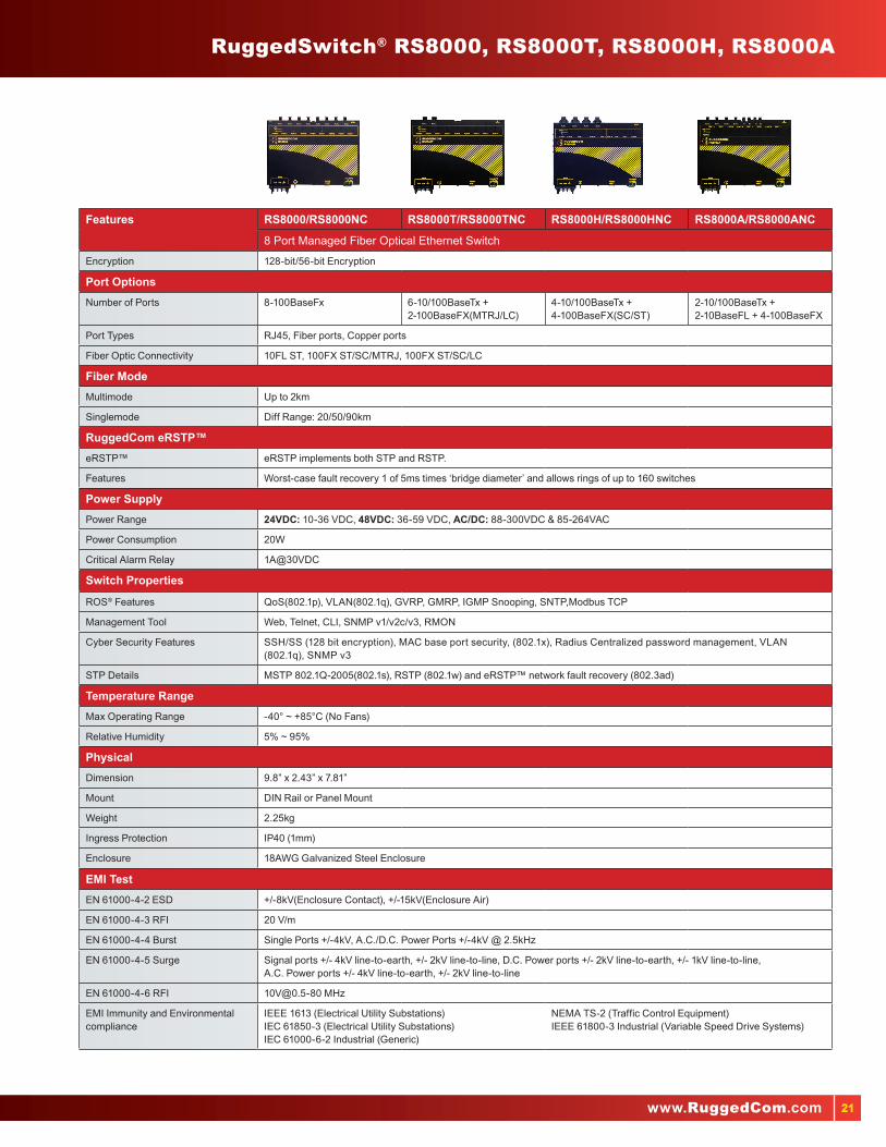
RuggedSwitch® RS8000, RS8000T, RS8000H, RS8000A
Features RS8000/RS8000NC RS8000T/RS8000TNC RS8000H/RS8000HNC RS8000A/RS8000ANC
8 Port Managed Fiber Optical Ethernet Switch
Encryption 128-bit/56-bit Encryption
Port Options
Number of Ports 8-100BaseFx 6-10/100BaseTx + 2-100BaseFX(MTRJ/LC)
4-10/100BaseTx + 4-100BaseFX(SC/ST)
2-10/100BaseTx + 2-10BaseFL + 4-100BaseFX
Port Types RJ45, Fiber ports, Copper ports
Fiber Optic Connectivity 10FL ST, 100FX ST/SC/MTRJ, 100FX ST/SC/LC
Fiber Mode
Multimode Up to 2km
Singlemode Diff Range: 20/50/90km
RuggedCom eRSTP™
eRSTP™ eRSTP implements both STP and RSTP.
Features Worst-case fault recovery 1 of 5ms times ‘bridge diameter’ and allows rings of up to 160 switches
Power Supply
Power Range 24VDC: 10-36 VDC, 48VDC: 36-59 VDC, AC/DC: 88-300VDC & 85-264VAC
Power Consumption 20W
Critical Alarm Relay 1A@30VDC
Switch Properties
ROS® Features QoS(802.1p), VLAN(802.1q), GVRP, GMRP, IGMP Snooping, SNTP,Modbus TCP
Management Tool Web, Telnet, CLI, SNMP v1/v2c/v3, RMON
Cyber Security Features SSH/SS (128 bit encryption), MAC base port security, (802.1x), Radius Centralized password management, VLAN (802.1q), SNMP v3
STP Details MSTP 802.1Q-2005(802.1s), RSTP (802.1w) and eRSTP™ network fault recovery (802.3ad)
Temperature Range
Max Operating Range -40° ~ +85°C (No Fans)
Relative Humidity 5% ~ 95%
Physical
Dimension 9.8” x 2.43” x 7.81”
Mount DIN Rail or Panel Mount
Weight 2.25kg
Ingress Protection IP40 (1mm)
Enclosure 18AWG Galvanized Steel Enclosure
EMI Test
EN 61000-4-2 ESD +/-8kV(Enclosure Contact), +/-15kV(Enclosure Air)
EN 61000-4-3 RFI 20 V/m
EN 61000-4-4 Burst Single Ports +/-4kV, A.C./D.C. Power Ports +/-4kV @ 2.5kHz
EN 61000-4-5 Surge Signal ports +/- 4kV line-to-earth, +/- 2kV line-to-line, D.C. Power ports +/- 2kV line-to-earth, +/- 1kV line-to-line,A.C. Power ports +/- 4kV line-to-earth, +/- 2kV line-to-line
EN 61000-4-6 RFI [email protected] MHz
EMI Immunity and Environmental compliance
IEEE 1613 (Electrical Utility Substations)IEC 61850-3 (Electrical Utility Substations)IEC 61000-6-2 Industrial (Generic)
NEMA TS-2 (Traffic Control Equipment)IEEE 61800-3 Industrial (Variable Speed Drive Systems)

22
RuggedSwitch® RS1600, RS8000
RS1600 - ____ - ____- ___- ___ - ___ - _____ PS1 PS2 FO MS RJ MOD
RS8000 - ____ - ___- ___ - _____ PS FO MS MOD
RS1600F - ____ - ____- _____- ____ - ____ - _____ PS1 PS2 MMX SMX MS MOD
RS8000A - ____ - ___- ___ - _____ PS FO MS MOD
RS8000T - ____ - ___ - _____ PS FO MOD
RS1600T - ____ - ____- ___- ____ - _____ PS1 PS2 FO MS MOD
RS8000H - ____ - ___ - _____ PS FO MOD
PS1 (Power Supply 1 Rating) �� 24 = 24VDC (10-36 VDC)�� 48 = 48VDC (36-59 VDC)�� HI = (88VDC-300VDC / 85VAC-264VAC)
PS2 (Redundant Power Supply 2 Rating)�� 0 = NONE (No redundant power supply)�� 24 = 24VDC (10-36 VDC)�� 48 = 48VDC (36-59 VDC)�� HI = (88VDC-300VDC / 85VAC-264VAC)
MMx (# Multimode 100BaseFX Fiber Ports) �� MMx = 1310nm, MM, 2km via SFF MTRJ connectors
(x = 0, 4, 8, 12, 16 )*
SMx (# Singlemode 100BaseFX Fiber Ports) �� SMx = 1310nm, SM, 15km via SFF LC connectors
(x = 0, 4, 8, 12, 16 )*
1600 FO (Fiber Options for 100BaseFX Ports)�� MM = 1310nm, MM, 2km via SFF MTRJ connectors�� SM = 1310nm, SM, 15km via SFF LC connectors
MS (Managed Switch Functions)�� UM = Unmanaged�� MS = Managed Switch option
RJ (RJ45 Uplink Ports Option)�� Blank = No RJ45 Uplink Ports�� RJ = RJ45 Uplink Ports option
Valid Order Code Examples�� RS1600-24-0-MM-UM�� RS1600-HI-48-SM-MS-RJ�� RS1600F-24-0-MM16-SM0-UM�� RS1600F-HI-48-MM8-SM8-MS�� RS1600F-HI-0-MM0-SM16-MS�� RS1600T-24-0-MM-UM�� RS1600T-HI-48-SM-MS�� RS1600T-HI-HI-0-UM
1600T FO (Fiber Options for 100BaseFX Ports) �� MM = 1310nm, MM, 2km via SFF MTRJ connectors�� SM = 1310nm, SM, 15km via SFF LC connectors�� 0 = No Fiber Ports
MOD: Manufacturing Modifications�� XX = None�� C01 = Conformal Coating
*Total MM and SM ports must equal 16
*MM= Multimode
*SM= SingleModermal Coating
PS (Power Supply)�� 24 = 24VDC (10-36 VDC)�� 48 = 48VDC (36-59 VDC)�� HI = (88VDC-300VDC / 85VAC-264VAC)
RS8000-FO (Fiber Options)�� MM = 1300nm, MM, 2km via SFF MTRJ connectors�� SM-X = 1310nm, SM, 15km via SFF LC connectors �� (X= 4 or 8 SM Fiber Ports)
RS8000A-FO (Fiber Options for 100BaseFX Ports Only)�� MM = 1300nm, MM, 2km via SFF MTRJ connectors�� SM = 1310nm, SM, 15km via SFF LC connectors
RS8000H-FO (Fiber Options)�� MMSC = 1300nm, MM, 2km via SC connectors�� MMST = 1300nm, MM, 2km via ST connectors�� SMSC = 1310nm, SM, 20km via SC connectors�� SMST = 1310nm, SM, 20km via ST connectors
RS8000T-FO (Fiber Options)�� MM = 1300nm, MM, 2km via SFF MTRJ connectors�� SM = 1310nm, SM, 15km via SFF LC connectors �� 0 = No Fiber Ports
MS (Managed Switch Functions)�� UM = Unmanaged�� MS = Managed Switch option
MOD: Manufaturing Modifications�� XX = None�� C01 = Conformal Coating*
*MM= Multimode
*SM= SingleModermal Coating

23www.RuggedCom.com
IP66/67 RuggedSwitch® RS969, M969
Features RuggedSwitch® RS969 / RS969NCIP66/IP67 Rated 10 Port Managed Ethernet Switch withGigabit Uplink Ports
RuggedSwitch® M969 / M969NCMIL-STD and IP66/IP67 Rated 10 Port ManagedEthernet Switch with Fiber Uplink Ports
Encryption 128-bit/56-bit Encryption
Port Options
Number of Ports 8 Fast Ethernet Ports (10/100BaseTX), 2 Fiber Optical Ethernet Ports (100BaseX and 1000BaseX)
Connectors IP66/IP67 Rated M12 D-code connectors & IP66/IP67 Rated shrouded RJ45 style connectors
Fiber Connector IP66/IP67 LC
Fiber Mode
Multimode Up to 500m
Singlemode Up to 25km
RuggedCom eRSTP™
eRSTP™ eRSTP implements both STP and RSTP.
Features Worst-case fault recovery of 5ms times ‘bridge diameter’ and allows rings of up to 160 switches
Power Supply
Power Range 24VDC: 10-36 VDC, 48VDC: 36-59 VDC, AC/DC: 88-300VDC & 85-264VAC
Power Consumption 10W
Critical Alarm Relay 1A@30VDC
Switch Properties
ROS® Features QoS(802.1p), VLAN(802.1q), GVRP, GMRP, IGMP Snooping, Link aggregation (802.3ad), SNTP, Modbus TCP
Management Tool Web, Telnet, CLI, SNMP v1/v2c/v3, RMON
Cyber Security Features SSH/SS (128 bit encryption), MAC base port security, (802.1x), Radius Centralized password management, VLAN (802.1q), SNMP v3
STP Details MSTP 802.1Q-2005(802.1s), RSTP (802.1w) and eRSTP™ network fault recovery (802.3ad)
Temperature Range
Max Operating Range -40° ~ +85°C (No Fans)
Relative Humidity 5% ~ 95%
Physical
Dimension 7.0” x 8.25” x 3.4”/3.75
Mount DIN rail or Panel Mounted
Weight 2.5kg
Ingress Protection IP66/IP67
Enclosure Cast Aluminum
EMI Test
EN 61000-4-2 ESD +/-8kV(Enclosure Contact), +/-15kV(Enclosure Air)
EN 61000-4-3 RFI 20 V/m
EN 61000-4-4 Burst A.C./D.C Power Ports +/-4kV, Signal ports+/-4kV @ 2.5kHz
EN 61000-4-5 Surge Signal ports +/- 4kV line-to-earth, +/- 2kV line-to-line, D.C. Power ports +/- 2kV line-to-earth, +/- 1kV line-to-line, A.C. Power ports +/- 4kV line-to-earth, +/- 2kV line-to-line
EN 61000-4-6 RFI [email protected] MHz
EMI Immunity and Environmental compliance
IEEE 1613 (Electrical Utility Substations)IEC 61850-3 (Electrical Utility Substations)IEEE 61800-3 Industrial (Variable Speed Drive Systems)IEC 61000-6-2 Industrial (Generic)NEMA TS-2 Traffic Control Equipment (pending)Hazardous Locations: Class 1, Div 2
MIL-STD 901D - Shock (Hard Mounted)MIL-STD 167 - VibrationMIL-STD 461 - EMIMIL-STD 1399 - Magnetic FieldMIL-STD 810 - Temperature and Humidity

24
Military Standard Ethernet Switches
Features MIL-STD RuggedSwitch® M2100/M2100NC19 Port Modular Managed Ethernet Switch with Gigabit Uplink Ports
MIL-STD RuggedSwitch® M2200/M2200NC9 Port Managed Gigabit Ethernet Switch
Encryption 128-bit/56-bit Encryption
Port Options
Number of Ports Up to 3 Gigabit Ethernet ports, up to 16 Fast Ethernet ports (Copper and/or Fiber)
Up to 9 Gigabit Ethernet ports (Copper and/or Fiber)
Port Type RJ45, Fiber Ports, Copper Ports
Fiber Connectors 10FL ST, 100FX ST/LC, 100FX ST/LC, 1000SX LC, 1000LX LC 1000SX LC, 1000LX LC
Fiber Mode
Multimode Up to 500m
Singlemode Diff Range:20/50/90km Diff Range:10/25km
RuggedCom eRSTP™
eRSTP™ eRSTP implements both STP and RSTP.
Features Worst-case fault recovery of 5ms times ‘bridge diameter’ and allows rings of up to 160 switches
Power Supply
Power Range 24VDC: 10-36 VDC, 1.2A 48VDC: 36-59 VDC, 0.6A AC/DC: 88-300VDC & 85-264VAC
Power Consumption 28W
Critical Alarm Relay Max Voltage: 250VAC, 125VDC, Max Current: 2A@250VAC, 2A@30VDC
Switch Properties
ROS® Features QoS(802.1p), VLAN(802.1q), GVRP, GMRP, IGMP Snooping, Link aggregation (802.3ad), SNTP, Modbus TCP
Management Tool Web, Telnet, CLI, SNMP v1/v2c/v3, RMON
Cyber Security Features SSH/SS (128 bit encryption), MAC base port security, (802.1x), Radius Centralized password management, VLAN (802.1q), SNMP v3
STP Details MSTP 802.1Q-2005(802.1s), RSTP (802.1w) and eRSTP™ network fault recovery (802.3ad)
Temperature Range
Max Operating Range -40° ~ +85°C (No Fans)
Relative Humidity 5% ~ 95%
Physical
Dimension 18.3” x 1.74” x 12.4”
Mount Panel Mount
Weight 5.2kg 4.8kg
Ingress Protection IP40 (1mm)
Enclosure 18 AWG Galvanized Steel Enclosure
EMI Test
EN 61000-4-2 ESD +/-8kV(Enclosure Contact), +/-15kV(Enclosure Air)
EN 61000-4-3 RFI 20 V/m
EN 61000-4-4 Burst A.C./D.C Power Ports +/-4kV, Signal ports+/-4kV @ 2.5kHz
EN 61000-4-5 Surge Signal ports +/- 4kV line-to-earth, +/- 2kV line-to-line, D.C. Power ports +/- 2kV line-to-earth, +/- 1kV line-to-line, A.C. Power ports +/- 4kV line-to-earth, +/- 2kV line-to-line
EN 61000-4-6 RFI [email protected] MHz
EMI Immunity and Environmental compliance
IEEE 1613 (Electrical Utility Substations)IEC 61850-3 (Electrical Utility Substations)IEEE 61800-3 Industrial (Variable Speed Drive Systems)IEC 61000-6-2 Industrial (Generic)NEMA TS-2 Traffic Control Equipment (pending)Hazardous Locations: Class 1, Div 2
MIL-STD 901D - Shock (Hard Mounted)MIL-STD 167 - VibrationMIL-STD 461 - EMIMIL-STD 1399 - Magnetic FieldMIL-STD 810 - Temperature and Humidity

25www.RuggedCom.com
RuggedSwitch® M2100, M2200, M969, RS969
M2100 - _____ - ______ - ____ - ____ - ___ - ___ - ___ - ___ - ___ - ___ - ___ - ___ - ___ - ____ Main Mount PS1 PS2 S1 S2 S3 S4 S5 S6 S7 S8 S9 S10
M2200 - _____ - ______ - ____ - ____ - ___ - ___ - ___ - ___ - ___ Main Mount PS1 PS2 S1 S2 S3 S4 S5
Main: Ethernet and Power Connectors�� B = Ethernet on rear; LED panel on top; power connector on rear�� T = Ethernet on front; LED panel on top; power connector on rear�� R = Ethernet on rear; LED panel on front; power connector on rear�� F = Ethernet on front; LED panel on front; power connector on rear
Mount: Mounting Options �� DP = Panel Mount Kit�� RM = 19” Rack Mount Kit2
�� 00 = No Mounting Option
PS1 and PS2: Power Supply 1 and 2�� 24 = 24VDC (10-36VDC), screw terminal block�� 48 = 48VDC (36-59VDC), screw terminal block�� HI = 88-300VDC or 85-264VAC, screw terminal block�� XX = No Power Supply (PS2 Only)
M2100 S1, S2, S3, S4, S7, S8, S9 and S10: Ethernet Modules for Slots 1, 2, 3, 4, 7, 8, 9 and 10�� XXXX = Empty�� TX02 = 2 x 10/100Tx Micro-D�� FL01 = 2 x 10FL - Multimode, 850nm, ST �� FX01 = 2 x 100FX - Multimode, 1310nm, ST �� FX11 = 2 x 100FX – Multimode, 1310nm, LC �� FX04 = 2 x 100FX - Singlemode, 1310nm, ST, 20km�� FX06 = 2 x 100FX - Singlemode, 1310nm, LC, 20km�� FX08 = 2 x 100FX - Singlemode, 1310nm, LC, 50km�� FX10 = 2 x 100FX - Singlemode, 1310nm, LC, 90km
M2100 S5: Gigabit Ethernet Modules for slot 5 M2200 S1, S2, S3, S4: Gigabit Ethernet Modules for Slots 1, 2, 3 & 4�� XXXX = Empty�� CG02 = 2 x 10/100/1000Tx Micro-D�� FG01 = 2 x 1000SX - Multimode, 850nm, LC, 500m�� FG03 = 2 x 1000LX - Singlemode, 1310nm, LC connectors, 10km�� FG05 = 2 x 1000LX - Singlemode, 1310nm, LC connectors, 25km
M2100 S6: Gigabit Ethernet Modules for slot 6 M2200 S5: Gigabit Ethernet Modules for slot 5�� �XXXXX = Empty�� �1CG02 = 1 x 10/100/1000Tx Micro-D �� �1FG01 = 1 x 1000SX - Multimode, 850nm, LC, 500m�� �1FG03 = 1 x 1000LX - Singlemode, 1310nm, LC connectors, 10km�� �1FG05 = 1 x 1000LX - Singlemode, 1310nm, LC connectors, 25km
Notes:
1 Distance ratings are typical but will depend on type of cabling, number of connectors and splices.
2 The unit is not rated for vibration and shock, MIL-STD-901D, while configured with the rack mount kit.
MODEL: Ethernet and Power Connectors�� Mini = 8 M12 D-Code Ethernet ports and “Mini-Change” power�� M23 = 8 M12 D-Code Ethernet ports and M23 power�� RJ45 = 8 RJ45 IP67 Ethernet ports and M23 power
PS1: Power Supply 1�� 24 = 24VDC (10 - 36VDC)�� 48 = 48VDC (36 - 59VDC)�� HI = 88-300VDC or 85-264VAC
PS2: Power Supply 2 (requires M23 Connector)�� 0 = None�� 24 = 24VDC (9 - 36VDC)�� 48 = 48TH (36 - 59VDC)�� HI = 88-300VDC or 85-264VAC
P9/P10: Port 9 & 10 IP67 Rated Fiber Optical Ports*�� XXXXX = None�� 1FG01 = 1000SX Multimode, LC, 850, 500m�� 1FG03 = 1000LX Singlemode, LC, 1310nm, 10km�� 1FG05 = 1000LX Singlemode, LC, 1310nm, 25km�� 1FX11 = 100FX – Multimode, 1300nm, LC �� 1FX06 = 100FX – Singlemode, 1300 nm, LC connectors, 20km �� 1FX08 = 100FX – Singlemode, 1300 nm, LC connectors, 50km �� 1FX10 = 100FX – Singlemode, 1300 nm, LC connectors, 90km
MOD: Manufacturing Modifications�� XX = None�� C01 = Conformal Coating
*Note: if 2 ports are selected, they must be the same option.
Slot 1
Slot 2
Slot 3
Slot 4
Slot 5
Slot 6
Slot 7
Slot 8
Slot 9
Slot 10M2100
Slot 1
Slot 2
Slot 3
Slot 4
Slot 5
Slot 6M2200
RS969 - _______ - ____ - ____ - ____ - ____ - _____ MODEL PS1 PS2 P9 P10 MOD
M969 - _______ - ____ - ____ - ____ - ____ MODEL PS1 PS2 P9 P10

26
RuggedSwitch® Managed Ethernet Switches
Features RuggedSwitch® RSG2100/RSG2100NC19 Port Modular Managed Ethernet Switch with Gigabit Uplink Ports
RuggedSwitch® RSG2100P/RSG2100PNC19 Port Managed Ethernet Switch with Integrated Power over Ethernet
Encryption 128-bit/56-bit Encryption
Port Options
Number of Ports Up to 16 Fast Ethernet ports (Copper and/or Fiber)Up to 3 Gigabit Ethernet ports (Copper and/or Fiber)2 port modules for tremendous flexibility
4-10/100BaseTx 802.3af (PoE) ports, Up to 3 Gigabit Ethernet ports - copper and/or fiber, Up to 12 Fast Ethernet ports - copper and/or fiber, Many fiber and connector options
Port Type RJ45, Fiber Ports, Copper Ports
Fiber Optic Connectivity 10FL ST, 100FX ST/SC/LC/MTRJ, 100FX ST/SC/LC, 1000SX LC, 1000LX SC/LC
Fiber Mode
Multimode Up to 500m
Singlemode 100M to 90km, 500M to 70km
RuggedCom eRSTP™
eRSTP™ eRSTP implements both STP and RSTP.
Features Worst-case fault recovery of 5ms times ‘bridge diameter’ and allows rings of up to 160 switches
Power Supply
Power Range 24VDC: 10-36 VDC, 1.2A 48VDC: 36-72 VDC, 0.6A Hi Voltage: AC/DC: 88-300VDC or 85-264VAC
24VDC: 10-36 VDC, 1.2A 48VDC: 36-59 VDC, 0.6AHi Voltage: AC/DC: 88-300VDC or 85-264VAC PoE Power Supply: 48VDC: 36-59VDC
Power Consumption 28W
Critical Alarm Relay Max Voltage: 250VAC, 125VDC, Max Current: 2A@250VAC, 2A@30VDC
Switch Properties
ROS® Features QoS(802.1p), VLAN(802.1q), GVRP, GMRP, IGMP Snooping, Link aggregation (802.3ad), SNTP, Modbus TCP
Management Tool Web, Telnet, CLI, SNMP v1/v2c/v3, RMON
Cyber Security Features SSH/SS (128 bit encryption), MAC base port security, (802.1x), Radius Centralized password management, VLAN (802.1q), SNMP v3
STP Details MSTP 802.1Q-2005(802.1s), RSTP (802.1w) and eRSTP™ network fault recovery (802.3ad)
Temperature Range
Max Operating Range -40° ~ +85°C (No Fans)
Relative Humidity 5% ~ 95%
Physical
Dimension 18.3” x 1.74” x 12.4”
Mount 19” Rack Mount, DIN rail or Panel Mounted
Weight 5.2kg
Ingress Protection IP40 (1mm)
Enclosure 18 AWG Galvanized Steel Enclosure
EMI Test
EN 61000-4-2 ESD +/-8kV(Enclosure Contact), +/-15kV(Enclosure Air)
EN 61000-4-3 RFI 20 V/m
EN 61000-4-4 Burst A.C./D.C Power Ports +/-4kV, Signal ports+/-4kV @ 2.5kHz
EN 61000-4-5 Surge Signal ports +/- 4kV line-to-earth, +/- 2kV line-to-line, D.C. Power ports +/- 2kV line-to-earth, +/- 1kV line-to-line, A.C. Power ports +/- 4kV line-to-earth, +/- 2kV line-to-line
EN 61000-4-6 RFI [email protected] MHz
EMI Immunity and Environmental compliance
IEEE 1613 (Electrical Utility Substations)IEC 61000-6-2 Industrial (Generic)NEMA TS-2 (Traffic Control Equipment)
IEC 61850-3 (Electrical Utility Substations) IEEE 61800-3 Industrial (Variable Speed Drive Systems)Hazardous Locations: Class 1, Div 2

27www.RuggedCom.com
Slot 1
Slot 2
Slot 3
Slot 4
Slot 5
Slot 6
Slot 7
Slot 8
Slot 9
Slot 10
RuggedSwitch® RSG2100, RSG2100P
RSG2100 - _____ - ______ - ____ - ____ - ___ - ___ - ___ - ___ - ___ - ___ - ___ - ___ - ___ - ___ - _____ Main Mount PS1 PS2 S1 S2 S3 S4 S5 S6 S7 S8 S9 S10 MOD
RSG2100P - _____ - ______ - ____ - ____ - ___ - ___ - ___ - ___ - ___ - ___ - ___ - ___ - _____ Main Mount PS1 PS2 S1 S2 S3 S4 S5 S6 S7 S8 MOD
Main: Ethernet and Power Connectors�� �R = Ethernet on rear; LED panel on front; power connector on rear�� �F = Ethernet on front; LED panel on front; power connector on rear�� �B = Ethernet on rear; LED panel on top; power connector on rear�� �T = Ethernet on front; LED panel on top; power connector on rear
Mount: Mounting Options �� RM = 19” Rack Mount Kit�� DP = DIN and Panel Mount Kit�� RD = 19” Rack, DIN, and Panel Mount Kit�� 00 = No Mounting Option
PS1 and PS2: Power Supply 1 and 2(5)
�� 24 = 24VDC (10-36VDC), screw terminal block�� 48 = 48VDC (36-72VDC), screw terminal block�� HI = 88-300VDC or 85-264VAC, screw terminal block�� 24P = 24VDC (10-36VDC), pluggable terminal block�� 48P = 48VDC (36-72VDC), pluggable terminal block�� HIP = 88-300VDC or 85-264VAC, pluggable terminal block�� XX = No Power Supply (PS2 Only)
S1, S2, S3, S4, S7, S8, S9 and S10: Ethernet Modules for Slots 1, 2, 3, 4, 7, 8, 9 and 10�� XXXX = Empty�� TX01 = 2 x 10/100Tx RJ45�� FL01 = 2 x 10FL - Multimode, 850nm, ST �� FX01 = 2 x 100FX - Multimode, 1300nm, ST �� FX02 = 2 x 100FX - Multimode, 1300nm, SC �� FX11 = 2 x 100FX – Multimode, 1300nm, LC �� FX03 = 2 x 100FX - Multimode, 1300nm, MTRJ �� FX04 = 2 x 100FX - Singlemode, 1310nm, ST, 20km�� FX05 = 2 x 100FX - Singlemode, 1310nm, SC, 20km�� FX06 = 2 x 100FX - Singlemode, 1310nm, LC, 20km�� FX07 = 2 x 100FX - Singlemode, 1310nm, SC, 50km�� FX08 = 2 x 100FX - Singlemode, 1310nm, LC, 50km�� FX09 = 2 x 100FX - Singlemode, 1310nm, SC, 90km�� FX10 = 2 x 100FX - Singlemode, 1310nm, LC, 90km
S5: Gigabit Ethernet Modules for slot 5�� XXXX = Empty�� CG01 = 2 x 10/100/1000Tx RJ45�� FG01 = 2 x 1000SX - Multimode, 850nm, LC, 500m�� FG02 = 2 x 1000LX - Singlemode, 1310nm, SC connectors, 10km�� FG03 = 2 x 1000LX - Singlemode, 1310nm, LC connectors, 10km
�� FG04 = 2 x 1000LX - Singlemode, 1310nm, SC connectors, 25km�� FG05 = 2 x 1000LX - Singlemode, 1310nm, LC connectors, 25km�� FG50 = 2 x 1000LX SFP - Blank (no optical transceiver)�� FG51 = 2 x 1000SX SFP - Multimode, 850nm, LC, 500m (3)
�� FG52 = 2 x 1000LX SFP - Singlemode, 1310nm, LC, 10km (3)
�� FG53 = 2 x 1000LX SFP - Singlemode, 1310nm, LC, 25km (3)
�� FG54 = 2 x 1000LX SFP - Singlemode, 1550nm, LC, 70km (2)(3)
�� FG70 = 2 x 1000LX GBIC - Blank (no optical transceiver)�� FG71 = 2 x 1000LX GBIC - Singlemode, 1310nm, SC, 10km (4)
�� FG72 = 2 x 1000LX GBIC - Singlemode, 1310nm, SC, 25km (4)
�� FG73 = 2 x 1000LX GBIC - Singlemode, 1550nm, SC, 70km (2)(4)
S6: Gigabit Ethernet Modules for slot 6�� XXXXX = Empty�� 1CG01 = 1 x 10/100/1000Tx RJ45�� 1FG01 = 1 x 1000SX - Multimode, 850nm, LC, 500m�� 1FG02 = 1 x 1000LX - Singlemode, 1310nm, SC connectors, 10km�� 1FG03 = 1 x 1000LX - Singlemode, 1310nm, LC connectors, 10km�� 1FG04 = 1 x 1000LX - Singlemode, 1310nm, SC connectors, 25km�� 1FG05 = 1 x 1000LX - Singlemode, 1310nm, LC connectors, 25km�� 1FG50 = 1 x 1000SX SFP - Blank (no optical transceiver)�� 1FG51 = 1 x 1000SX SFP - Multimode, 850nm,LC, 500m (3)
�� 1FG52 = 1 x 1000LX SFP - Singlemode, 1310nm, LC,10km (3)
�� 1FG53 = 1 x 1000LX SFP - Singlemode, 1310nm, LC, 25km (3)
�� 1FG54 = 1 x 1000LX SFP - Singlemode, 1550nm, LC, 70km (2)(3)�� 1FG70 = 1 x 1000LX GBIC - Blank (no optical transceiver)�� 1FG71 = 1 x 1000LX GBIC - Singlemode, 1310nm, SC, 10km (4)
�� 1FG72 = 1 x 1000LX GBIC - Singlemode, 1310nm, SC, 25km (4)
�� 1FG73 = 1 x 1000LX GBIC - Singlemode, 1550nm, SC, 70km (2)(4)
MOD: Manufacturing Modifications�� XX = None�� C01 = Conformal Coating
Notes:1 Distance ratings are typical but will depend on type of cabling, number of connectors and splices.
2 These transceivers have an operating temperature range of -20 °C to +85°C. All other transceivers have an operating temperature range of -40°C to +85°C
3 SFP plugable optics that consist of a blank cage (FG50 for dual, 1FG50 for single) plus specified fiber optic interface(s) installed
4 GBIC plugable optics that consist of a blank cage (FG70 for dual, 1FG70 for single) plus specified fiber optic interface(s) installed
5 Power Supply 1 and 2 must be either both screw terminal block or both pluggable terminal block
Slot 1
Slot 2
Slot 3
Slot 4
Slot 5
Slot 6
Slot 7
Slot 8
Slot 9
Slot 10

28
RuggedSwitch® Managed Ethernet Switches
Features RuggedSwitch® RSG2200/RS2200NC 9 Port Managed Gigabit Ethernet Switch
RuggedSwitch® RSG2288/RS2288NC Modular Managed Gigabit Switch with IEEE 1588 v2 and IRIG-B
RuggedSwitch® RSG2300/RS2300NC 32 Port Managed Ethernet Switch with 4 Modular Gigabit Uplink Ports
Encryption 128-bit/56-bit Encryption
Port Options
Number of Ports Up to 9 Gigabit Ethernet ports(Copper and/or Fiber)Up to 9-100FX Fiber Fast Ethernet ports.
Up to 9 Gigabit Ethernet ports(Copper and/or Fiber)Up to 9-100FX Fiber Fast Ethernet ports.
24-10/100TX copper ports, Optional: Up to 4-1000LX Gigabit Ethernet ports (Copper and/or Fiber) and Up to 8-100FX Fiber Fast Ethernet ports
Port Type RJ45, Fiber Ports, Copper Ports
Fiber Optic Connectivity 10FL ST, 100FX ST/SC/LC/MTRJ, 100FX ST/SC/LC, 1000SX LC, 1000LX SC/LC
Fiber Mode
Multimode Up to 500m
Singlemode 100M to 90km, 500M to 70km
RuggedCom eRSTP™
eRSTP™ eRSTP implements both STP and RSTP.
Features Worst-case fault recovery of 5ms times ‘bridge diameter’ and allows rings of up to 160 switches
Power Supply
Power Range 24VDC: 10-36 VDC, 48VDC: 36-72 VDC, AC/DC: 88-300VDC & 85-264VAC
Power Consumption 28W 28W 32W
Critical Alarm Relay Max Voltage: 250VAC, 125VDC Max Current: 2A@250VAC, 2A@30VDC
Switch Properties
ROS® Features QoS(802.1p), VLAN(802.1q), GVRP, GMRP, IGMP Snooping, Link aggregation (802.3ad), SNTP, Modbus TCP
Management Tool Web, Telnet, CLI, SNMP v1/v2c/v3, RMON
Cyber Security Features SSH/SS (128 bit encryption), MAC base port security, (802.1x), Radius Centralized password management, VLAN (802.1q), SNMP v3
STP Details MSTP 802.1Q-2005(802.1s), RSTP (802.1w) and eRSTP™ network fault recovery (802.3ad)
Temperature Range
Max Operating Range -40° ~ +85°C (No Fans)
Relative Humidity 5% ~ 95%
Physical
Dimension 18.3” x 1.74” x 12.4”
Mount 19” Rack Mount, DIN rail or Panel Mounted
Weight 4.8kg 4.8kg 5.2kg
Ingress Protection IP40 (1mm)
Enclosure 18 AWG Galvanized Steel Enclosure
EMI Test
EN 61000-4-2 ESD +/-8kV(Enclosure Contact), +/-15kV(Enclosure Air)
EN 61000-4-3 RFI 20 V/m
EN 61000-4-4 Burst A.C./D.C Power Ports +/-4kV, Signal ports+/-4kV @ 2.5kHz
EN 61000-4-5 Surge Signal ports +/- 4kV line-to-earth, +/- 2kV line-to-line, D.C. Power ports +/- 2kV line-to-earth, +/- 1kV line-to-line, A.C. Power ports +/- 4kV line-to-earth, +/- 2kV line-to-line
EN 61000-4-6 RFI [email protected] MHz
EMI Immunity and Environmental compliance
IEEE 1613 (Electrical Utility Substations)IEC 61000-6-2 Industrial (Generic)NEMA TS-2 (Traffic Control Equipment)
IEC 61850-3 (Electrical Utility Substations) IEEE 61800-3 Industrial (Variable Speed Drive Systems)

29www.RuggedCom.com
RuggedSwitch® RSG2200, RSG2288, RSG2300
RSG2288 - _____ - ______ - ____ - ____ - ___ - ___ - ___ - ___ - ___ - ___ - _____ Main Mount PS1 PS2 S1 S2 S3 S4 S5 S6 MOD
RSG2300 - _____ - ______ - ____ - ____ - ___ - ___ - ___ - ___ - _____ Main Mount PS1 PS2 S1 S2 S3 S4 MOD
RSG2200 - _____ - ______ - ____ - ____ - ___ - ___ - ___ - ___ - ___ - _____ Main Mount PS1 PS2 S1 S2 S3 S4 S5 MOD
Main: Ethernet and Power Connectors�� R = Ethernet on rear; LED panel on front; power connector on rear�� F = Ethernet on front; LED panel on front; power connector on rear�� B = Ethernet on rear; LED panel on top; power connector on rear�� T = Ethernet on front; LED panel on top; power connector on rear
Mount: Mounting Options�� RM = 19” Rack Mount Kit�� DP = DIN and Panel Mount Kit�� RD = 19” Rack, DIN, and Panel Mount Kit�� 00 = No Mounting Option
PS1 and PS2: Power Supply 1 and 25
�� 24 = 24VDC (10-36VDC), screw terminal block�� 48 = 48VDC (36-72VDC), screw terminal block�� HI = 88-300VDC or 85-264VAC, screw terminal block�� 24P = 24VDC (9-36VDC), pluggable terminal block�� 48P = 48VDC (36-72VDC), pluggable terminal block�� HIP = 88-300VDC or 85-264VAC, pluggable terminal block�� XX = No Power Supply (PS2 Only)
RSG2200/RSG2288 – S1, S2, S3, S4: Gigabit Ethernet Modules for Slots 1, 2, 3, and 4 RSG2300 – S3 & S4: 100FX/Gigabit Ethernet Modules for Slots 3 & 4�� XXXX = Empty�� CG01 = 2 x 10/100/1000Tx RJ45�� FG01 = 2 x 1000SX - Multimode, 850nm, LC, 500m�� FG02 = 2 x 1000LX - Singlemode, 1310nm, SC connectors, 10km�� FG03 = 2 x 1000LX - Singlemode, 1310nm, LC connectors, 10km�� FG04 = 2 x 1000LX - Singlemode, 1310nm, SC connectors, 25km�� FG05 = 2 x 1000LX - Singlemode, 1310nm, LC connectors, 25km�� FG50 = 2 x 1000LX SFP - Blank (no optical transceiver)�� FG51 = 2 x 1000SX SFP - Multimode, 850nm, LC, 500m�� FG52 = 2 x 1000LX SFP - Singlemode, 1310nm, LC, 10km�� FG53 = 2 x 1000LX SFP - Singlemode, 1310nm, LC, 25km�� FG54 = 2 x 1000LX SFP - Singlemode, 1550nm, LC, 70km (2)
�� FG70 = 2 x 1000LX GBIC - Blank (no optical transceiver)�� FG71 = 2 x 1000LX GBIC - Singlemode, 1310nm, SC, 10km�� FG72 = 2 x 1000LX GBIC - Singlemode, 1310nm, SC, 25km�� FG73 = 2 x 1000LX GBIC - Singlemode, 1550nm, SC, 70km (2)
�� FXA01 = 2 x 100FX - Multimode, 1300nm, ST�� FXA02 = 2 x 100FX - Multimode, 1300nm, SC�� FXA11 = 2 x 100FX – Multimode, 1300nm, LC�� FXA03 = 2 x 100FX - Multimode, 1300nm, MTRJ�� FXA04 = 2 x 100FX - Singlemode, 1310nm, ST, 20km�� FXA05 = 2 x 100FX - Singlemode, 1310nm, SC, 20km�� FXA06 = 2 x 100FX - Singlemode, 1310nm, LC, 20km�� FXA07 = 2 x 100FX - Singlemode, 1310nm, SC, 50km�� FXA08 = 2 x 100FX - Singlemode, 1310nm, LC, 50km�� FXA09 = 2 x 100FX - Singlemode, 1310nm, SC, 90km�� FXA10 = 2 x 100FX - Singlemode, 1310nm, LC, 90km
RSG2300 – S1, and S2: Ethernet Modules for Slots 1 and 2�� XXXX = Empty�� TX01 = 2 x 10/100Tx RJ45�� FL01 = 2 x 10FL - Multimode, 850nm, ST �� FX01 = 2 x 100FX - Multimode, 1300nm, ST �� FX02 = 2 x 100FX - Multimode, 1300nm, SC
�� FX11 = 2 x 100FX – Multimode, 1300nm, LC �� FX03 = 2 x 100FX - Multimode, 1300nm, MTRJ �� FX04 = 2 x 100FX - Singlemode, 1310nm, ST, 20km�� FX05 = 2 x 100FX - Singlemode, 1310nm, SC, 20km�� FX06 = 2 x 100FX - Singlemode, 1310nm, LC, 20km�� FX07 = 2 x 100FX - Singlemode, 1310nm, SC, 50km�� FX08 = 2 x 100FX - Singlemode, 1310nm, LC, 50km�� FX09 = 2 x 100FX - Singlemode, 1310nm, SC, 90km�� FX10 = 2 x 100FX - Singlemode, 1310nm, LC, 90km
RS2200/RSG228 – S5: Gigabit Ethernet Modules for Slot 5�� XXXXX = Empty�� 1CG01 = 1 x 10/100/1000Tx RJ45�� 1FG01 = 1 x 1000SX - Multimode, 850nm, LC, 500m�� 1FG02 = 1 x 1000LX - Singlemode, 1310nm, SC connectors, 10km�� 1FG03 = 1 x 1000LX - Singlemode, 1310nm, LC connectors, 10km�� 1FG04 = 1 x 1000LX - Singlemode, 1310nm, SC connectors, 25km�� 1FG05 = 1 x 1000LX - Singlemode, 1310nm, LC connectors, 25km�� 1FG50 = 1 x 1000LX SFP - Blank (no optical transceiver)�� 1FG51 = 1 x 1000SX SFP - Multimode, 850nm, LC, 500m (3)
�� 1FG52 = 1 x 1000LX SFP - Singlemode, 1310nm, LC,10km (3)
�� 1FG53 = 1 x 1000LX SFP - Singlemode, 1310nm, LC, 25km (3)
�� 1FG54 = 1 x 1000LX SFP - Singlemode, 1550nm, LC, 70km (2) (3)
�� 1FG70 = 1 x 1000LX GBIC - Blank (no optical transceiver)�� 1FG71 = 1 x 1000LX GBIC - Singlemode, 1310nm, SC, 10km (4)
�� 1FG72 = 1 x 1000LX GBIC - Singlemode, 1310nm, SC, 25km (4)
�� 1FG73 = 1 x 1000LX GBIC - Singlemode, 1550nm, SC, 70km (2)(4)
�� 1FXA01 = 1 x 100FX - Multimode, 1300nm, ST�� 1FXA02 = 1 x 100FX - Multimode, 1300nm, SC�� 1FXA11 = 1 x 100FX – Multimode, 1300nm, LC�� 1FXA03 = 1 x 100FX - Multimode, 1300nm, MTRJ�� 1FXA04 = 1 x 100FX - Singlemode, 1310nm, ST, 20km�� 1FXA05 = 1 x 100FX - Singlemode, 1310nm, SC, 20km�� 1FXA06 = 1 x 100FX - Singlemode, 1310nm, LC, 20km�� 1FXA07 = 1 x 100FX - Singlemode, 1310nm, SC, 50km�� 1FXA08 = 1 x 100FX - Singlemode, 1310nm, LC, 50km�� 1FXA09 = 1 x 100FX - Singlemode, 1310nm, SC, 90km�� 1FXA10 = 1 x 100FX - Singlemode, 1310nm, LC, 90km
RSG2288 – S6: RSG2288 Modules for Slot 6�� XXX = Empty�� PTP1 = Precision Time Protocol (PTP) Source Card: Inputs - GPS,
IRIG-B, Outputs - IRIG-B AM and TTL
MOD: Manufacturing Modifications�� XX = None�� C01 = Conformal Coating
Accessories/Options41-11-0011 - Cable support bracket (one) 43-10-0007 - Power cable (North America three prong connector -> beau)
Notes: 1 Distance ratings are typical but will depend on type of cabling, number of connectors and splices.
2 These transceivers have an operating temperature range of -20 °C to +85°C. All other transceivers have an operating temperature range of -40°C to +85°C
3 Base unit comes standard with 24 10/100TX RJ45 ports
4 SFP plugable optics that consist of a blank cage (FG50 for dual, 1FG50 for single) plus specified fiber optic interface(s) installed
5 GBIC plugable optics that consist of a blank cage (FG70 for dual, 1FG70 for single) plus specified fiber optic interface(s) installed
6 Power Supply 1 and 2 must be either both screw terminal block or both pluggable terminal block
Slot 1
Slot 2
Slot 3
Slot 4
Slot 5
Slot 6

30
RuggedSwitch® Managed Ethernet Switches
Features RuggedSwitch® RSG2300P32 Port Managed Ethernet Switch with Integrated Power over Ethernet
RuggedSwitch® RSG2300PNC32 Port Managed Ethernet Switch with Integrated Power over Ethernet
Encryption 128-bit Encryption 56-bit Encryption
Port Options
Number of Ports 4-10/100BaseTx 802.3af (PoE) ports, Up to 4 Gigabit Ethernet ports - copper and/or fiber, Up to 24 Fast Ethernet ports - copper and/or fiber,Many fiber and connector options
4-10/100BaseTx 802.3af (PoE) ports, Up to 4 Gigabit Ethernet ports - copper and/or fiber, Up to 24 Fast Ethernet ports - copper and/or fiber,Many fiber and connector options
Port Type RJ45, Fiber Ports, Copper Ports
Fiber Optic Connectivity 10FL ST, 100FX ST/SC/LC/MTRJ, 100FX ST/SC/LC, 1000SX LC, 1000LX SC/LC
Fiber Mode
Multimode Up to 500m
Singlemode 100M to 90km, 500M to 70km
RuggedCom eRSTP™
eRSTP™ eRSTP implements both STP and RSTP.
Features Worst-case fault recovery of 5ms times ‘bridge diameter’ and allows rings of up to 160 switches
Power Supply
Power Range 24VDC: 10-36 VDC, 1.2A 48VDC: 36-72 VDC, 0.6A Hi Voltage: AC/DC: 88-300VDC or 85-264VAC PoE Power Supply: 48VDC: 36-59VDC
Power Consumption 32W
Critical Alarm Relay Max Voltage: 250VAC, 125VDC, Max Current: 2A@250VAC, 2A@30VDC
Switch Properties
ROS® Features QoS(802.1p), VLAN(802.1q), GVRP, GMRP, IGMP Snooping, Link aggregation (802.3ad), SNTP, Modbus TCP
Management Tool Web, Telnet, CLI, SNMP v1/v2c/v3, RMON
Cyber Security Features SSH/SS (128 bit encryption), MAC base port security, (802.1x), Radius Centralized password management, VLAN (802.1q), SNMP v3
STP Details MSTP 802.1Q-2005(802.1s), RSTP (802.1w) and eRSTP™ network fault recovery (802.3ad)
Temperature Range
Max Operating Range -40° ~ +85°C (No Fans)
Relative Humidity 5% ~ 95%
Physical
Dimension 18.3” x 1.74” x 12.4”
Mount 19” Rack Mount, DIN rail or Panel Mounted
Weight 5.2kg
Ingress Protection IP40 (1mm)
Enclosure 18 AWG Galvanized Steel Enclosure
EMI Test
EN 61000-4-2 ESD +/-8kV(Enclosure Contact), +/-15kV(Enclosure Air)
EN 61000-4-3 RFI 20 V/m
EN 61000-4-4 Burst A.C./D.C Power Ports +/-4kV, Signal ports+/-4kV @ 2.5kHz
EN 61000-4-5 Surge Signal ports +/- 4kV line-to-earth, +/- 2kV line-to-line, D.C. Power ports +/- 2kV line-to-earth, +/- 1kV line-to-line, A.C. Power ports +/- 4kV line-to-earth, +/- 2kV line-to-line
EN 61000-4-6 RFI [email protected] MHz
EMI Immunity and Environmental compliance
IEEE 1613 (Electrical Utility Substations)IEC 61000-6-2 Industrial (Generic)NEMA TS-2 (Traffic Control Equipment)
IEC 61850-3 (Electrical Utility Substations) IEEE 61800-3 Industrial (Variable Speed Drive Systems)Hazardous Locations: Class 1, Div 2

31www.RuggedCom.com
RuggedSwitch® RSG2300P, RSG2300PNC
RSG2300P - _____ - ______ - ____ - ____ - ___ - ___ - ___ - ___ - _____ Main Mount PS1 PS2 S1 S2 S3 S4 MOD
RSG2300PNC - _____ - ______ - ____ - ____ - ___ - ___ - ___ - ___ - _____ Main Mount PS1 PS2 S1 S2 S3 S4 MOD
Main: Ethernet and Power Connectors�� R = Ethernet on rear; LED panel on front; power connector on rear�� F = Ethernet on front; LED panel on front; power connector on rear�� B = Ethernet on rear; LED panel on top; power connector on rear�� T = Ethernet on front; LED panel on top; power connector on rear
Mount: Mounting Options �� RM = 19” Rack Mount Kit�� DP = DIN and Panel Mount Kit�� RD = 19” Rack, DIN, and Panel Mount Kit�� 00 = No Mounting Option
PS1: Unit Power Supply�� 24 = 24VDC (10-36VDC), screw terminal block�� 48 = 48VDC (36-59VDC), screw terminal block�� HI = 88-300VDC or 85-265VAC, screw terminal block�� 24P = 24VDC (10-36VDC), pluggable terminal block�� 48P = 48VDC (36-59VDC), pluggable terminal block�� HIP = 88-300VDC or 85-265VAC, pluggable terminal block
PS2: PoE Power Supply�� 48PoE = 48VDC (36-59VDC) PoE Power Supply
S1:Ethernet Modules for Slot 1�� XXXX = Empty�� PX01 = 2 additional 10/100 Base Tx PoE ports�� FL01 = 2 x 10FL - Multimode, 850nm, ST �� FX01 = 2 x 100FX - Multimode, 1300nm, ST �� FX02 = 2 x 100FX - Multimode, 1300nm, SC �� FX11 = 2 x 100FX - Multimode, 1300nm, LC �� FX03 = 2 x 100FX - Multimode, 1300nm, MTRJ �� FX04 = 2 x 100FX - Singlemode, 1310nm, ST, 20km�� FX05 = 2 x 100FX - Singlemode, 1310nm, SC, 20km�� FX06 = 2 x 100FX - Singlemode, 1310nm, LC, 20km�� FX07 = 2 x 100FX - Singlemode, 1310nm, SC, 50km�� FX08 = 2 x 100FX - Singlemode, 1310nm, LC, 50km�� FX09 = 2 x 100FX - Singlemode, 1310nm, SC, 90km�� FX10 = 2 x 100FX - Singlemode, 1310nm, LC, 90km
The RSG2100P comes standard with 4-10/100BaseTX 802.3af (PoE) compliant Ethernet ports
S2: PoE Module for Slot 2�� PX01 = 2 x 10/100 BaseTx PoE ports
S3 and S4: 100FX/Gigabit Ethernet Modules for Slots 3 and 4�� XXXX = Empty�� CG01 = 2 x 10/100/1000Tx RJ45�� FG01 = 2 x 1000SX - Multimode, 850nm, LC, 500m�� FG02 = 2 x 1000LX - Singlemode, 1310nm, SC connectors, 10km�� FG03 = 2 x 1000LX - Singlemode, 1310nm, LC connectors, 10km�� FG04 = 2 x 1000LX - Singlemode, 1310nm, SC connectors, 25km�� FG05 = 2 x 1000LX - Singlemode, 1310nm, LC connectors, 25km�� FG50 = 2 x 1000LX SFP - Blank (no optical transceiver)�� FG51 = 2 x 1000SX SFP - Multimode, 850nm, LC, 500m (4)
�� FG52 = 2 x 1000LX SFP - Singlemode, 1310nm, LC, 10km (4)
�� FG53 = 2 x 1000LX SFP - Singlemode, 1310nm, LC, 25km (4)
�� FG54 = 2 x 1000LX SFP - Singlemode, 1550nm, LC, 70km (2)(4)
�� FG70 = 2 x 1000LX GBIC - Blank (no optical transceiver)�� FG71 = 2 x 1000LX GBIC - Singlemode, 1310nm, SC, 10km (5)
�� FG72 = 2 x 1000LX GBIC - Singlemode, 1310nm, SC, 25km (5)
�� FG73 = 2 x 1000LX GBIC - Singlemode, 1550nm, SC, 70km (2)(5)
�� FXA01 = 2 x 100FX - Multimode, 1300nm, ST�� FXA02 = 2 x 100FX - Multimode, 1300nm, SC�� FXA11 = 2 x 100FX – Multimode, 1300nm, LC�� FXA03 = 2 x 100FX - Multimode, 1300nm, MTRJ�� FXA04 = 2 x 100FX - Singlemode, 1310nm, ST, 20km�� FXA05 = 2 x 100FX - Singlemode, 1310nm, SC, 20km�� FXA06 = 2 x 100FX - Singlemode, 1310nm, LC, 20km�� FXA07 = 2 x 100FX - Singlemode, 1310nm, SC, 50km�� FXA08 = 2 x 100FX - Singlemode, 1310nm, LC, 50km�� FXA09 = 2 x 100FX - Singlemode, 1310nm, SC, 90km�� FXA10 = 2 x 100FX - Singlemode, 1310nm, LC, 90km
MOD: Manufaturing Modifications�� XX = None�� C01 = Conformal Coating
Notes:1 Distance ratings are typical but will depend on type of cabling, number of connectors and splices.
2 These transceivers have an operating temperature range of -20 °C to +85°C. All other transceivers have an operating temperature range of -40°C to +85°C
3 Base unit comes standard with 24 10/100TX RJ45 ports
4 SFP plugable optics that consist of a blank cage (FG50 for dual, 1FG50 for single) plus specified fiber optic interface(s) installed
5 GBIC plugable optics that consist of a blank cage (FG70 for dual, 1FG70 for single) plus specified fiber optic interface(s) installed

32
RuggedVDSL™ EoVDSL Ethernet Switches
Features RS900L / RS900LNC RS910L / RS910LNC RS920L / RS920LNC RS930L / RS930LNC
Encryption 128-bit/56-bit Encryption
Port Options
Number of Ports 6 (10/100BaseTX), Add 2 (10/100BaseTX or 100BaseFX), EoVDSL Interface
Up to 1 (EoVDSL) interface, Up to 2 Serial and/or 2 Fast Ethernet Ports.
Up to 2 (EoVDSL interface) Up to 2 RS485/422/232 Serial Ports(DB9 or RJ45)
Up to 6 Fast Ethernet ports (10/100BaseTX) Up to 2 EoVDSL interface
Ethernet over VDSL RJ11, Symmetric data rates up to 35Mbps, Asymmetric data rates up to 40Mbps
Serial Connectors RS485/RS422/RS232 Serial Ports (DB9 or RJ45) & Serial Fiber Interface (ST) available
Port Types RJ45, Fiber ports, Copper ports, Serial ports
Fiber Optic Connectivity 10FL ST, 100FX ST/SC/MTRJ, 100FX ST/SC/LC
Fiber Mode
Ethernet over VDSL 5km
Multimode Up to 2km
Singlemode Diff Range: 20/50/90km
RuggedCom eRSTP™
eRSTP™ eRSTP implements both STP and RSTP.
Features Worst-case fault recovery 1 of 5ms times ‘bridge diameter’ and allows rings of up to 160 switches
Power Supply
Power Range 24VDC: 10-36 VDC, 48VDC: 36-59 VDC, AC/DC: 88-300VDC & 85-264VAC
Power Consumption 10W
Critical Alarm Relay 1A@30VDC
Switch Properties
ROS® Features QoS(802.1p), VLAN(802.1q), GVRP, GMRP, IGMP Snooping, Link aggregation (802.3ad) SNTP, Modbus TCP
Management Tool Web, Telnet, CLI, SNMP v1/v2c/v3, RMON
Cyber Security Features SSH/SS (128 bit encryption), MAC base port security, (802.1x), Radius Centralized password management, VLAN (802.1q), SNMP v3
STP Details MSTP 802.1Q-2005(802.1s), RSTP (802.1w) and eRSTP™ network fault recovery (802.3ad)
Temperature Range
Max Operating Range -40° ~ +85°C (No Fans)
Relative Humidity 5% ~ 95%
Physical
Dimension 2.6” x 7.4” x 5.0”
Mount DIN Rail or Panel Mount
Weight 1.2kg
Ingress Protection IP40 (1mm)
Enclosure 20AWG Galvanized Steel Enclosure
EMI Test
EN 61000-4-2 ESD +/-8kV(Enclosure Contact), +/-15kV(Enclosure Air)
EN 61000-4-3 RFI 20 V/m
EN 61000-4-4 Burst Single Ports +/-4kV, A.C./D.C. Power Ports +/-4kV @ 2.5kHz
EN 61000-4-5 Surge Signal ports +/- 4kV line-to-earth, +/- 2kV line-to-line, D.C. Power ports +/- 2kV line-to-earth, +/- 1kV line-to-line, A.C. Power ports +/- 4kV line-to-earth, +/- 2kV line-to-line
EN 61000-4-6 RFI [email protected] MHz
EMI Immunity and Environmental compliance
IEEE 1613 (Electrical Utility Substations)IEC 61850-3 (Electrical Utility Substations)IEC 61000-6-2 Industrial (Generic)
NEMA TS-2 (Traffic Control Equipment)IEEE 61800-3 Industrial (Variable Speed Drive Systems)Hazardous Locations: Class 1, Div 2

33www.RuggedCom.com
RuggedVDSL™ RS900L, RS910L, RS920L, RS930L
RS900L - ____ - ___- ___- ____ - ____ - _____ PS M P7 P8 VV MOD
RS910L - ____ - ___ - ___ - ___ - ____ - _____ PS M S E VV MOD
RS930L - ____ - ___ - ____ - ____ - _____ PS M VV1 VV2 MOD
RS920L - ____ - ___ - ___ - ____ - ____ - _____ PS M S VV1 VV2 MOD
PS: Power Supply�� 24 = 24 VDC (10-36VDC)�� 48 = 48 VDC (36-72VDC)�� HI = 87-264VAC or 88-300VDC
M: Mounting Option�� D = DIN Rail�� P = Panel Mount�� N = None
RS900L – P7, P8: Additional Ethernet Ports�� XX = None�� TX = 1 x 10/100BaseTX (if selected, P7 & P8 must both be TX)�� MJ = Multimode 1300nm, MTRJ connector�� MC = Multimode 1300nm, SC connector�� MT = Multimode 1300nm, ST connector�� ML = Multimode 1300nm, LC connector�� T2 = Singlemode 1310nm, ST connector, Standard 20km�� L2 = Singlemode 1310nm, LC connector, Standard 20km�� L5 = Singlemode 1310nm, LC connector, Intermediate Reach 50km�� L9 = Singlemode 1310nm, LC connector, Long Reach 90km�� C2 = Singlemode 1310nm, SC connector, Standard 20km�� C5 = Singlemode 1310nm, SC connector, Intermediate Reach 50km�� C9 = Singlemode 1310nm, SC connector, Long Reach 90km
RS910L – E: Additional Ethernet Ports�� XXXX = No Ethernet Ports�� TX01 = 2 x 10/100TX RJ45�� FL01 = 2 x 10FL - Multimode, 850 nm, ST connectors�� FX01 = 2 x 100FX - Multimode, 1300 nm, ST connectors�� FX02 = 2 x 100FX - Multimode, 1300 nm, SC connectors�� FX03 = 2 x 100FX - Multimode, 1300 nm, MTRJ connectors�� FX11 = 2 x 100FX - Multi mode, 1300nm, LC connectors�� FX04 = 2 x 100FX - Singlemode, 1300 nm, ST connectors, 20km�� FX05 = 2 x 100FX - Singlemode, 1300 nm, SC connectors, 20km�� FX06 = 2 x 100FX - Singlemode, 1300 nm, LC connectors, 20km�� FX07 = 2 x 100FX - Singlemode, 1300 nm, SC connectors, 50km�� FX08 = 2 x 100FX - Singlemode, 1300 nm, LC connectors, 50km�� FX09 = 2 x 100FX - Singlemode, 1300 nm, SC connectors, 90km
RS910L/RS920L – S: Serial Port Options�� XX = None�� S1 = 2 x RS232/422/485 DB9�� S2 = 2 x RS232/422/485 RJ45�� S3 = 2 x Fiber 850nm ST
RS900L/RS910L – VV: VDSL Interface�� V1 = Standard reach (<2.5km)�� V2 = Long Reach (5km) Master / CO�� V3 = Long Reach (5km) / CPE
RS920L/RS930L – VV1, VV2: VDSL Interface�� V1 = Standard reach (<2.5km)�� V2 = Long Reach (5km) Master / CO�� V3 = Long Reach (5km) / CPE
Power Cables�� 43-10-0008 - Bare-wire�� 43-10-0007 - with lugs
MOD: Manufacturing Modifications�� XX = None�� C01 = Conformal Coating

34
RuggedAIR™ Wireless LAN Devices
Features RS900W / RS900WNC RS910W / RS910WNC RS920W / RS920WNC RS930W / RS930WNC
Encryption 128-bit/56-bit Encryption
Port Options
Number of Ports 6 Fast Ethernet ports(10/100BaseTX)Optional 2 (10/100BaseTXor 100BaseFX)
2 Fast Ethernet ports(10/100BaseTX or100BaseFX), 2 Serial ports,(Db9 or RJ45)
1 Ethernet over VDSL(EoVDSL) interface2 RS485/RS422/RS232Serial Ports (DB9 or RJ45)
1 Ethernet over VDSL(EoVDSL) interface6 Fast Ethernet Ports(10/100BaseTX)
Port Types RJ45, Fiber ports, Copper ports, Serial Ports. EoVDSL
Connectors RS485/RS422/RS232,(DB9 or RJ45), ST
Ethernet over VDSL One EoVDSL port, RJ11 connector, Symmetrical data rates up to 50Mbps
Fiber Optic Connectivity Multimode : MRTJ/ST/SC/LC , Singlemode: LC/SC/ST
Fiber Mode
Ethernet over VDSL N/A N/A Up to 5km Up to 5km
Multimode Up to 2km
Singlemode Diff Range: 20/50/90km
Wireless Specifications
Antenna type Removable, Upgradable 3dBi Antenna with R-SMA (male) connector
Operating channels/ frequency- range
11 channels, 2.400 - 2.4720 GHz (US, Canada)13 channels, 2.400 - 2.4835 GHz (ETSI)14 channels, 2.400 - 2.4970 GHz (Japan)
Data rates IEEE 802.11b: 11/5.5/2/1 MbpsIEEE 802.11g: 54/48/36/24/18/12/9/6 Mbps
Modulation Technology IEEE 802.11b: DSSS over CCK (11/5 Mbps), DQPSK (2 Mbps), DBPSK (1 Mbps)IEEE 802.11g: OFDM over 64QAM, 16QAM, QPSK, BPSK
Transmit Power IEEE 802.11b: 20dBm nominal @ 11 MbpsIEEE 802.11g: 16dBm nominal @ 54 Mbps
Receiver Sensitivity IEEE 802.11b: -88dBm @ 11 Mbps with 8% FERIEEE 802.11g: -74dBm @ 54 Mbps with 10% FER
RuggedCom eRSTP™
eRSTP™ eRSTP implements both STP and RSTP.
Features Worst-case fault recovery 1 of 5ms times ‘bridge diameter’ and allows rings of up to 160 switches
Power Supply
Power Range 24VDC: 10-36 VDC, 48VDC: 36-72 VDC, Universal high-voltage range: 88-300VDC & 85-264VAC
Power Consumption 10W
Critical Alarm Relay Form-c failsafe contact relay: 1A@30VDC
Switch Properties
ROS® Features QoS(802.1p), VLAN(802.1q), GVRP, GMRP, IGMP Snooping, Link aggregation (802.3ad) SNTP, Modbus TCP
Management Tool Web, Telnet, CLI, SNMP v1/v2c/v3, RMON
Cyber Security Features SSH/SS (128 bit encryption), MAC base port security, (802.1x), Radius Centralized password management, VLAN (802.1q), SNMP v3
STP Details MSTP 802.1Q-2005(802.1s), RSTP (802.1w) and eRSTP™ network fault recovery (802.3ad)
Temperature Range
Max Operating Range -40° ~ +85°C (No Fans)
Relative Humidity 5% ~ 95%

35www.RuggedCom.com
Physical
Dimension 2.6” x 7.4” x 5.0”
Mount DIN Rail or Panel Mount
Weight 1.2kg
Ingress Protection IP40 (1mm)
Enclosure 20AWG Galvanized Steel Enclosure
EMI Test
EN 61000-4-2 ESD +/-8kV(Enclosure Contact), +/-15kV(Enclosure Air)
EN 61000-4-3 RFI 20 V/m
EN 61000-4-4 Burst Single Ports +/-4kV, A.C./D.C. Power Ports +/-4kV @ 2.5kHz
EN 61000-4-5 Surge Signal ports +/- 4kV line-to-earth, +/- 2kV line-to-line, D.C. Power ports +/- 2kV line-to-earth, +/- 1kV line-to-line, A.C. Power ports +/- 4kV line-to-earth, +/- 2kV line-to-line
EN 61000-4-6 RFI [email protected] MHz
EMI Immunity and Environmental compliance
IEEE 1613 (Electrical Utility Substations)IEC 61850-3 (Electrical Utility Substations)IEC 61000-6-2 Industrial (Generic)
NEMA TS-2 (Traffic Control Equipment)IEEE 61800-3 Industrial (Variable Speed Drive Systems)Hazardous Locations: Class 1, Div 2
RS900W - ____ - ___- ___- ____ - ____ - _____ PS M P7 P8 WW MODBase unit includes 802.11i wireless interface and 6 10/100BaseTx Ethernet ports
RS910W - ____ - ___ - ___ - ___ - ____ - _____ PS M S E WW MOD
RS930W - ____ - ___ - ____ - ____ - _____ PS M VV WW MODBase Unit includes 802.11 wireless interface and 10/100BaseTx Ethernet ports
RS920W - ____ - ___ - ___ - ____ - _____ PS M S VV MOD
PS: Power Supply�� 24 = 24VDC (10-36VDC)�� 48 = 48VDC (36-72VDC)�� HI = 85-264VAC or 88-300VDC
M: Mounting Option�� D = DIN Rail�� P = Panel Mount�� N = None
RS900W – P7, P8: Additional Ethernet Ports�� XX = None�� TX = 1 x 10/100BaseTX (if selected, P7 & P8 must both be TX) �� MJ = 1 x 100BaseFX – Multimode, MTRJ connector�� MC = 1 x 100BaseFX – Multimode, SC connector�� MT = 1 x 100BaseFX – Multimode, ST connector�� ML = 1 x 100BaseFX – Multimode, LC connector�� T2 = 1 x 100BaseFX – Singlemode, ST connector, 20km�� L2 = 1 x 100BaseFX – Singlemode, LC connector, 20km�� L5 = 1 x 100BaseFX – Singlemode LC connector, 50km�� L9 = 1 x 100BaseFX – Singlemode LC connector, 90km�� C2 = 1 x 100BaseFX – Singlemode SC connector, 20km�� C5 = 1 x 100BaseFX – Singlemode SC connector, 50km�� C9 = 1 x 100BaseFX – Singlemode SC connector, 90km
RS910W/RS920W – S: Serial Port Options�� XX = None�� S1 = 2 x RS232/422/485 DB9�� S2 = 2 x RS232/422/485 RJ45�� S3 = 2 x Fiber 850nm ST
RS910W – E: Ethernet Ports Options�� XXXX = No Ethernet ports�� TX01 = 2 x 10/100Tx RJ45
�� FL01 = 2 x 10FL - Multimode, 850 nm, ST connectors�� FX01 = 2 x 100FX - Multimode, 1300 nm, ST connectors�� FX02 = 2 x 100FX - Multimode, 1300 nm, SC connectors�� FX03 = 2 x 100FX - Multimode, 1300 nm, MTRJ connectors�� FX11 = 2 x 100FX - Multi mode, 1300nm, LC connectors �� FX04 = 2 x 100FX - Singlemode, 1300 nm, ST connectors, 20km�� FX05 = 2 x 100FX - Singlemode, 1300 nm, SC connectors, 20km�� FX06 = 2 x 100FX - Singlemode, 1300 nm, LC connectors, 20km�� FX07 = 2 x 100FX - Singlemode, 1300 nm, SC connectors, 50km�� FX08 = 2 x 100FX - Singlemode, 1300 nm, LC connectors, 50km�� FX09 = 2 x 100FX - Singlemode, 1300 nm, SC connectors, 90km�� FX10 = 2 x 100FX - Singlemode, 1300 nm, LC connectors, 90km
RS920W/RS930W – VV: VDSL Interface�� V1 = Standard reach (<2.5km)�� V2 = Long Reach (5km) Master / CO�� V3 = long Reach (5km) /CPE
WW: Wireless Options�� W1 = 802.11 - US (North America)�� W2 = 802.11 - EU (European Union)�� W3 = 802.11 - CH (China)(Coming soon)�� W4 = 802.11 - AU (Australia)�� W6 = 802.11 - IN (India)
MOD: Manufaturing Modifications�� XX = None�� C01 = Conformal Coating
Power Cables�� 43-10-0008 - Bare-wire�� 43-10-0007 - with lugs

36
RuggedServer™ Serial Device Servers
Features RS910/RS910NC RS400/RS400NC RS401/RS401NC RMC30
Encryption 128-bit/56-bit Encryption
Port Options
Number of Ports Up to 3 fast Ethernet ports (Copper and/ or fiber). Integrated Switch.
Integrated Ethernet switch- Up to 4 ports
Integrated Ethernet switch - Up to 4 ports
2-Port Serial-to-Ethernet Converter
Port Type RJ45, Fiber Port, Copper Port, Serial port
Fiber Optic Connectivity 10FL ST, 100FX ST/SC/LC/MTRJ, 100FX ST/SC/LC
Fiber Mode
Multimode Up to 100m
Singlemode 100M to 90km
RuggedCom eRSTP™
eRSTP™ eRSTP implements both STP and RSTP.
Features Worst-case fault recovery of 5ms times ‘bridge diameter’ and allows rings of up to 160 switches
Power Supply
Power Range 24VDC: 10-36 VDC, 48VDC: 36-59 VDC, High Voltage AC/DC: 88-300VDC & 85-264VAC
Power Consumption 10W 8W 8W 2W
Critical Alarm Relay Form-C failsafe contact relay: 1A@30VDC
Switch Properties
ROS® Features QoS(802.1p), VLAN(802.1q), GVRP, GMRP, IGMP Snooping, Link aggregation (802.3ad), SNTP, Modbus TCP
Management Web, Telnet, CLI, SNMP v1/v2c/v3, RMON
Cyber Security Features SSH/SS (128 bit encryption), MAC base port security, (802.1x), Radius Centralized password management, VLAN (802.1q), SNMP v3
STP Details MSTP 802.1Q-2005(802.1s), RSTP (802.1w) and eRSTP™ network fault recovery (802.3ad)
Temperature Range
Max Operating Range -40° ~ +85°C (No Fans)
Relative Humidity 5% ~ 95%
Physical
Dimension 2.6” x 7.4”x 5.0” 7.96” x 1.74”x 11.47” 6.76” x 3.5”x 7.42” 2.3” x 4.3”x 3.7”
Mount DIN rail or Panel Mounted
Weight 1.2kg 2.2kg 2.2kg 0.68kg
Ingress Protection IP40 (1mm)
Enclosure 20 AWG Galvanized Steel Enclosure
18 AWG Galvanized Steel Enclosure 21 AWG galvanized steel enclosure
EMI Test
EN 61000-4-2 ESD +/-8kV(Enclosure Contact), +/-15kV(Enclosure Air)
EN 61000-4-3 RFI 20 V/m
EN 61000-4-4 Burst A.C./D.C Power Ports +/-4kV, Signal ports+/-4kV @ 2.5kHz
EN 61000-4-5 Surge Signal ports +/- 4kV line-to-earth, +/- 2kV line-to-line, D.C. Power ports +/- 2kV line-to-earth, +/- 1kV line-to-line, A.C. Power ports +/- 4kV line-to-earth, +/- 2kV line-to-line
EN 61000-4-6 RFI [email protected] MHz
EMI Immunity and Environmental compliance
IEEE 1613 (Electrical Utility Substations)IEC 61000-6-2 Industrial (Generic)NEMA TS-2 (Traffic Control Equipment)
IEC 61850-3 (Electrical Utility Substations) IEEE 61800-3 Industrial (Variable Speed Drive Systems) Hazardous Locations: Class 1, Div 2
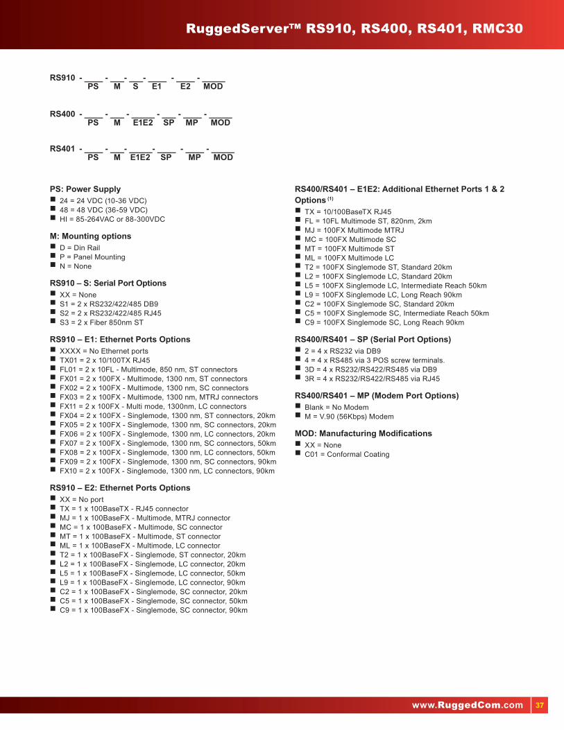
37www.RuggedCom.com
RuggedServer™ RS910, RS400, RS401, RMC30
RS910 - ____ - ___- ___- ____ - ____ - _____ PS M S E1 E2 MOD
RS401 - ____ - ___- _____- ____ - ____ - _____ PS M E1E2 SP MP MOD
RS400 - ____ - ___ - _____ - ___ - ____ - _____ PS M E1E2 SP MP MOD
PS: Power Supply�� 24 = 24 VDC (10-36 VDC)�� 48 = 48 VDC (36-59 VDC)�� HI = 85-264VAC or 88-300VDC
M: Mounting options�� D = Din Rail �� P = Panel Mounting�� N = None
RS910 – S: Serial Port Options�� XX = None�� S1 = 2 x RS232/422/485 DB9�� S2 = 2 x RS232/422/485 RJ45�� S3 = 2 x Fiber 850nm ST
RS910 – E1: Ethernet Ports Options�� XXXX = No Ethernet ports�� TX01 = 2 x 10/100TX RJ45�� FL01 = 2 x 10FL - Multimode, 850 nm, ST connectors�� FX01 = 2 x 100FX - Multimode, 1300 nm, ST connectors�� FX02 = 2 x 100FX - Multimode, 1300 nm, SC connectors�� FX03 = 2 x 100FX - Multimode, 1300 nm, MTRJ connectors�� FX11 = 2 x 100FX - Multi mode, 1300nm, LC connectors �� FX04 = 2 x 100FX - Singlemode, 1300 nm, ST connectors, 20km�� FX05 = 2 x 100FX - Singlemode, 1300 nm, SC connectors, 20km�� FX06 = 2 x 100FX - Singlemode, 1300 nm, LC connectors, 20km�� FX07 = 2 x 100FX - Singlemode, 1300 nm, SC connectors, 50km�� FX08 = 2 x 100FX - Singlemode, 1300 nm, LC connectors, 50km�� FX09 = 2 x 100FX - Singlemode, 1300 nm, SC connectors, 90km�� FX10 = 2 x 100FX - Singlemode, 1300 nm, LC connectors, 90km
RS910 – E2: Ethernet Ports Options�� XX = No port�� TX = 1 x 100BaseTX - RJ45 connector�� MJ = 1 x 100BaseFX - Multimode, MTRJ connector�� MC = 1 x 100BaseFX - Multimode, SC connector�� MT = 1 x 100BaseFX - Multimode, ST connector�� ML = 1 x 100BaseFX - Multimode, LC connector�� T2 = 1 x 100BaseFX - Singlemode, ST connector, 20km�� L2 = 1 x 100BaseFX - Singlemode, LC connector, 20km�� L5 = 1 x 100BaseFX - Singlemode, LC connector, 50km�� L9 = 1 x 100BaseFX - Singlemode, LC connector, 90km�� C2 = 1 x 100BaseFX - Singlemode, SC connector, 20km�� C5 = 1 x 100BaseFX - Singlemode, SC connector, 50km�� C9 = 1 x 100BaseFX - Singlemode, SC connector, 90km
RS400/RS401 – E1E2: Additional Ethernet Ports 1 & 2 Options (1)
�� TX = 10/100BaseTX RJ45 �� FL = 10FL Multimode ST, 820nm, 2km �� MJ = 100FX Multimode MTRJ�� MC = 100FX Multimode SC�� MT = 100FX Multimode ST�� ML = 100FX Multimode LC�� T2 = 100FX Singlemode ST, Standard 20km�� L2 = 100FX Singlemode LC, Standard 20km�� L5 = 100FX Singlemode LC, Intermediate Reach 50km�� L9 = 100FX Singlemode LC, Long Reach 90km�� C2 = 100FX Singlemode SC, Standard 20km�� C5 = 100FX Singlemode SC, Intermediate Reach 50km�� C9 = 100FX Singlemode SC, Long Reach 90km
RS400/RS401 – SP (Serial Port Options)�� 2 = 4 x RS232 via DB9�� 4 = 4 x RS485 via 3 POS screw terminals.�� 3D = 4 x RS232/RS422/RS485 via DB9�� 3R = 4 x RS232/RS422/RS485 via RJ45
RS400/RS401 – MP (Modem Port Options)�� Blank = No Modem�� M = V.90 (56Kbps) Modem
MOD: Manufacturing Modifications�� XX = None�� C01 = Conformal Coating

38
RuggedServer™ Serial Device Servers
Features RS416/RS416NC RS416P/RS416PNC
Encryption 128-bit/56-bit Encryption
Port Options
Number of Ports Up to 4 Fast Ethernet Ports, 10/100TX RJ 45, 10 FLMultimode, 100 FX Multimode, IEEE 1588
Optional 2 Fast Ethernet Ports, 10/100TX RJ 45, 10 FL Multimode, 100 FX Multimode
Serial Ports Up to 16 Serial Ports, Software Selectable RS232/RS422/RS485, Db9 or RJ 45 connectors
Port Type RJ45, Fiber Ports, Copper Ports
Fiber Optic Connectivity 10FL ST, 100FX ST/SC/LC/MTRJ, 100FX ST/SC/LC, 1000SX LC, 1000LX SC/LC
Fiber Mode
Multimode Up to 100m
Singlemode 100M to 90km
RuggedCom eRSTP™
eRSTP™ eRSTP implements both STP and RSTP.
Features Worst-case fault recovery of 5ms times ‘bridge diameter’ and allows rings of up to 160 switches
Power Supply
Power Range 24VDC: 10-36 VDC, 1.2A 48VDC: 36-59 VDC, 0.6A Hi Voltage: AC/DC: 88-300VDC or 85-264VAC (max)
24VDC: 10-36 VDC, 1.2A 48VDC: 36-59 VDC, 0.6AHi Voltage: AC/DC: 88-300VDC or 85-264VAC (max)PoE Power Supply: 48VDC: 36-59VDC
Power Consumption 15W
Critical Alarm Relay 2A@30VDC
Switch Properties
ROS® Features QoS(802.1p), VLAN(802.1q), GVRP, GMRP, IGMP Snooping, Link aggregation (802.3ad), SNTP, Modbus TCP
Management Web, Telnet, CLI, SNMP v1/v2c/v3, RMON
Cyber Security Features SSH/SS (128 bit encryption), MAC base port security, (802.1x), Radius Centralized password management, VLAN (802.1q), SNMP v3
STP Details MSTP 802.1Q-2005(802.1s), RSTP (802.1w) and eRSTP™ network fault recovery (802.3ad)
Temperature Range
Max Operating Range -40° ~ +85°C (No Fans)
Relative Humidity 5% ~ 95%
Physical
Dimension 18.3” x 1.74” x 12.4”
Mount 19” Rack Mount, DIN rail or Panel Mounted
Weight 5.2kg
Ingress Protection IP40 (1mm)
Enclosure 18 AWG Galvanized Steel Enclosure
EMI Test
EN 61000-4-2 ESD +/-8kV(Enclosure Contact), +/-15kV(Enclosure Air)
EN 61000-4-3 RFI 20 V/m
EN 61000-4-4 Burst A.C./D.C Power Ports +/-4kV, Signal ports+/-4kV @ 2.5kHz
EN 61000-4-5 Surge Signal ports +/- 4kV line-to-earth, +/- 2kV line-to-line, D.C. Power ports +/- 2kV line-to-earth, +/- 1kV line-to-line, A.C. Power ports +/- 4kV line-to-earth, +/- 2kV line-to-line
EN 61000-4-6 RFI [email protected] MHz
EMI Immunity and Environmental compliance
IEEE 1613 (Electrical Utility Substations)IEC 61000-6-2 Industrial (Generic)NEMA TS-2 (Traffic Control Equipment)
IEC 61850-3 (Electrical Utility Substations) IEEE 61800-3 Industrial (Variable Speed Drive Systems)Hazardous Locations: Class 1, Div 2

39www.RuggedCom.com
RuggedServer™ RS416, RS416P
Main: Ethernet and Power Connectors�� R = Ethernet on rear; LED panel on front; power connector on rear�� F = Ethernet on front; LED panel on front; power connector on rear�� B = Ethernet on rear; LED panel on top; power connector on rear�� T = Ethernet on front; LED panel on top; power connector on rear
Mount: Mounting Options�� RM = 19” Rack Mount Kit�� DP = DIN and Panel Mount Kit�� RD = 19” Rack, DIN, and Panel Mount Kit�� 00 = No Mounting Option
RS416 – PS1 and PS2: Power Supply 1 and 2RS416P – PS1: Unit Power Supply�� 24 = 24VDC (10-36VDC), screw terminal block�� 48 = 48VDC (36-59VDC), screw terminal block�� HI = 88-300VDC or 85-264VAC, screw terminal block�� 24P = 24VDC (10-36VDC), pluggable terminal block�� 48P = 48VDC (36-59VDC), pluggable terminal block�� HIP = 88-300VDC or 85-264VAC, pluggable terminal block�� XX = No Power Supply (PS2 Only)
RS416P – PS2: PoE Power Supply�� 48PoE = 48VDC (36-59VDC) PoE Power Supply
S1, S2, S3, S4: Serial Port Modules for Slots 1, 2, 3, and 4 2
�� XX = Empty (S2,S3,S4 Only)�� 3D = 4 x RS232/RS422/RS485 via DB9�� 3R = 4 x RS232/RS422/RS485 via RJ45�� FS = 4 x Fiber Serial Interface (ST Connector)�� ID = 4 x RS232/RS422/RS485 & IRIG-B via DB9 1
�� IR = 4 x RS232/RS422/RS485 & IRIG-B via RJ45 1
RS416 – S5, S6: Ethernet Modules for Slots 5 and 6 (2)
RS416P – S5: Ethernet Modules for Slots 5�� XXXX = Empty (S6 Only)�� PX01 = 2 additional 10/100 BaseTx PoE Ports (RS416P)�� TX01 = 2 x 10/100Tx RJ45�� FL01 = 2 x 10FL - Multimode, 850nm, ST�� FX01 = 2 x 100FX - Multimode, 1300nm, ST�� FX02 = 2 x 100FX - Multimode, 1300nm, SC�� FX11 = 2 x 100FX – Multimode, 1300nm, LC�� FX03 = 2 x 100FX - Multimode, 1300nm, MTRJ�� FX04 = 2 x 100FX - Singlemode, 1300nm, ST, 20km�� FX05 = 2 x 100FX - Singlemode, 1300nm, SC, 20km�� FX06 = 2 x 100FX - Singlemode, 1300nm, LC, 20km�� FX07 = 2 x 100FX - Singlemode, 1300nm, SC, 50km�� FX08 = 2 x 100FX - Singlemode, 1300nm, LC, 50km�� FX09 = 2 x 100FX - Singlemode, 1300nm, SC, 90km�� FX10 = 2 x 100FX - Singlemode, 1300nm, LC, 90km�� IRIG = 1 x IRIG-B in, BNC, 1 x IRIG-B out, BNC (S5 only)
RS416P – S6: PoE Ethernet Modules for Slots 6�� PX01 =2 10/100 BaseTx PoE Ports
MOD: Manufacturing Modifications�� XX = None�� C01 = Conformal Coating
Notes:1. When IR or ID are ordered the IRIG module must be ordered for slot 5
2. IEEE 1588 Hardware Assist and Internal clock capable units are only available on units sold with the IRIG module
Slot 5
Slot 6RS416
Slot 1
Slot 2
Slot 3
Slot 4
Slot 5
Slot 6 RS416P
Slot 1
Slot 2
Slot 3
Slot 4
RS416 - _____ - ______ - ____ - ____ - ___ - ___ - ___ - ___ - ___ - ___ - _____ Main Mount PS1 PS2 S1 S2 S3 S4 S5 S6 MOD
RS416P - _____ - ______ - ____ - ____ - ___ - ___ - ___ - ___ - ___ - ___ - _____ Main Mount PS1 PS2 S1 S2 S3 S4 S5 S6 MOD

40
RuggedBackbone™ RX1500, RX1501
Features RX1500Industrially Hardened Layer 3 Switch and Router
RX1501Industrially Hardened Layer 3 Switch and Router
Port Options
Number of Ports Up to 16 ports 100FX, Up to 24-ports 10/100TX,Up to 8 ports Gigabit Ethernet, Up to 4 T1/E1 portsUp to 18 RS232/422/485 Serial,All modules are field replaceable
Up to 4 10/100/1000 Base Tx ports or 36-10/100 Tx portsUp to 24 100FX or 4-optical Gigabit ports,Up to 30 RS232/422/485 Serial, Up to 4 T1/E1 ports
Serial Ports Up to 16 Serial Ports, Software Selectable RS232/RS422/RS485, Db9 or RJ 45 connectors
Port Type RJ45, Fiber ports, Copper ports, Serial ports, Pluggable Optics (SFP)
Fiber Optic Connectivity 10FL ST, 100FX ST/SC/LC/MTRJ, 100FX ST/SC/LC, 1000SX LC, 1000LX SC/LC
Fiber Mode
Multimode Up to 2km
Singlemode Diff Range: 20/50/90km
RuggedCom eRSTP™
eRSTP™ eRSTP implements both STP and RSTP
Features Worst-case fault recovery of 5ms times ‘bridge diameter’ and allows rings of up to 160 switches
Power Supply
Power Range Lo Voltage: 9-72 VDC Hi Voltage: AC/DC: 88-300VDC or 85-264VAC
Power Consumption 40W Max
Critical Alarm Relay 5A@30VDC, 8A@250VAC
Switch Properties
ROX™II Features QoS(802.1p), VLAN(802.1Q), GVRP, GMRP, IGMP Snooping, Link aggregation (802.3ad), Broadcast Storm Filtering, SNTP, Modbus TCP. Simple plug and play operation, Port Rate Limiting, Port Mirroring, BGPv4, OSPFv2, RIP v1/2
Management Web, Telnet, CLI, SNMP v1/v2c/v3, RMON
Cyber Security Features SSH/SSL (128 bit encryption), MAC base port security, (802.1x), VLAN (802.1Q), SNMP v3
STP Details MSTP 802.1Q-2005(802.1s), RSTP (802.1w) and eRSTP™ network fault recovery (802.3ad)
Temperature Range
Max Operating Range -40° ~ +85°C (No Fans)
Relative Humidity 5% ~ 95%
Physical
Dimension 17.36” x 1.74” x 11.9”
Mount 19” Rack Mount, DIN rail or Panel Mounted
Weight 5.2kg
Ingress Protection IP40 (1mm)
Enclosure Aluminum steel enclosure
EMI Test
EN 61000-4-2 ESD +/-8kV(Enclosure Contact), +/-15kV(Enclosure Air)
EN 61000-4-3 RFI 20 V/m
EN 61000-4-4 Burst A.C./D.C Power Ports +/-4kV, Signal ports+/-4kV @ 2.5kHz
EN 61000-4-5 Surge Signal ports +/- 4kV line-to-earth, +/- 2kV line-to-line, D.C. Power ports +/- 2kV line-to-earth, +/- 1kV line-to-line, A.C. Power ports +/- 4kV line-to-earth, +/- 2kV line-to-line
EN 61000-4-6 RFI [email protected] MHz
EMI Immunity and Environmental compliance
IEEE 1613 (Electrical Utility Substations)IEC 61000-6-2 Industrial (Generic)NEMA TS-2 (Traffic Control Equipment)
IEC 61850-3 (Electrical Utility Substations) IEEE 61800-3 Industrial (Variable Speed Drive Systems)Hazardous Locations: Class 1, Div 2

41www.RuggedCom.com
LM1
LM2
LM3
LM4 PM1 PM2
RX1500
ST: Switch Type Hardware�� L2 = Layer 2 Switch�� L3 = Layer 3 Switch
Mount: Mounting Options�� RM = 19” Rack Mount Kit�� 00 = No Mounting Option
PM1 and PM2: Power Modules�� HI = 88-300 VDC or 85-264VAC, screw terminal block�� HIP = 88-300 VDC or 85-264VAC, pluggable terminal block�� XXP = No Power Supply (PM2 only)
SFT: Software�� L2SE = Layer 2 Standard Edition�� L3SE = Layer 3 Standard Edition
LM1 through LM6 Line Modules
Blank Module�� XX = Blank Module
Copper Ethernet Modules�� 6TX01 = 6 x 10/100TX RJ45�� CG01 = 2x 10/100/1000TX RJ45 1
100BaseFX modules with 2 Ports 1
�� FX01 = 2 x 100FX - Multimode, 1300nm, ST connectors, 2km�� FX02 = 2 x 100FX - Multimode, 1300nm, SC connectors, 2km�� FX11 = 2 x 100FX - Multimode, 1300nm, LC connectors, 2km�� FX03 = 2 x 100FX - Multimode, 1300nm, MTRJ connectors, 2km�� FX04 = 2 x 100FX - Singlemode, 1300nm, ST connectors, 20km�� FX05 = 2 x 100FX - Singlemode, 1300nm, SC connectors, 20km�� FX06 = 2 x 100FX - Singlemode, 1300nm, LC connectors, 20km�� FX07 = 2 x 100FX - Singlemode, 1300nm, SC connectors, 50km�� FX08 = 2 x 100FX - Singlemode, 1300nm, LC connectors, 50km�� FX09 = 2 x 100FX - Singlemode, 1300nm, SC connectors, 90km�� FX10 = 2 x 100FX - Singlemode, 1300nm, LC connectors, 90km
100BaseFX modules with 4 Ports�� 4FX11 = 4 x 100FX - Multimode, 1300nm, LC connectors, 2km�� 4FX03 = 4 x 100FX - Multimode, 1300nm, MTRJ connectors, 2km�� 4FX06 = 4 x 100FX - Singlemode, 1300nm, LC connectors, 20km�� 4FX08 = 4 x 100FX - Singlemode, 1300nm, LC connectors, 50km�� 4FX10 = 4 x 100FX - Singlemode, 1300nm, LC connectors, 90km
Gigabit Ethernet Modules modules with 2 Ports 1
�� FG01 = 2 x 1000SX Multimode, 850 nm, LC, 500m�� FG02 = 2 x 1000LX Singlemode 1300 nm, SC, 10km�� FG03 = 2 x 1000LX Singlemode 1300 nm, LC, 10km�� FG04 = 2 x 1000LX Singlemode 1300 nm, SC, 25km�� FG05 = 2 x 1000LX Singlemode 1300 nm, LC, 25km�� FG50 = 2 x 1000LX SFP Blank(no optical transceiver)�� FG51 = 2 x 1000SX SFP Multimode, 850 nm, LC, 500m�� FG52 = 2 x 1000LX SFP Singlemode, 1310 nm, LC, 10km�� FG53 = 2 x 1000LX SFP Singlemode, 1310 nm, LC, 25km�� FG54 = 2 x 1000LX SFP Singlemode, 1550 nm, LC, 70km
WAN Port Options 2
�� TC1 = Single T1/E1 via RJ45 (Channelized/Unchannelized)�� TC2 = Dual T1/E1 via RJ45 (Channelized/Unchannelized)�� TC4 = Quad T1/E1 via RJ45 (Channelized/Unchannelized)�� E01 = Single E1 75 Ohms via BNC (Channelized/Unchannelized)�� E02 = Dual E1 75 Ohms via BNC (Channelized/Unchannelized)
MOD: Hardware Modifications�� XX = None�� C01 = With Conformal Coating
Notes:
1. On the RX1501 these modules may only be selected for LM1 and LM2.
2. Only one T1/E1 module may be used per router.
RX1500 - ___ - _____ - ____ - ____ - ____ - ____ - ____ - ____ - ____ - _____ ST MNT PM1 PM2 SFT LM1 LM2 LM3 LM4 MOD
RX1501 - ___ - _____ - ____ - ____ - ____ - ____ - ____ - ____ - ____ - ____ - _____ ST MNT PM1 SFT LM1 LM2 LM3 LM4 LM5 LM6 MOD
LM1
LM2
LM3 LM5
LM4 LM6 PM1
RX1501

42
RuggedBackbone™ RX1510, RX1511, RX1512
Features RX1510 Hardened Ethernet Switch and Router with Optional Redundant Power Supply
RX1511 Hardened Ethernet Switch and Router Ideal for Pole & DIN Rail Mounting
RX1512 Hardened Ethernet Switch and Router Ideal for Pole & DIN Rail Mounting
Compact, Modular, Field Hot-Swappable Layer 3 Switching and Routing Platform with Integrated Cyber Security Appliance Functions
Port Options
Number of Ports Up to 24 10/100BaseTx, Up to 8 Gigabit Ports, Up to 4 T1/E1 ports, Up to 18 RS232/422/485, Up to 16 100BaseFx Ports
Up to 12 10/100TX or 8-100FX ports, Up to 4 Giga Ethernet Ports, Single/Dual/Quad T1/E1 modules
Up to 12 10/100TX or 8-100FX ports, Up to 4 Gigabit Ethernet Ports,Single/Dual/Quad T1/E1 modules
Port Type RJ45, Fiber Port, Copper Port, Serial port
Fiber Optic Connectivity 100FX ST/SC/LC/MTRJ, 1000SX LC, 1000LX SC/LC
Fiber Mode
Multimode Up to 2km
Singlemode 100FX 2km to 90km, Gigabit 500m to 70km
RuggedCom eRSTP™
eRSTP™ eRSTP implements both STP and RSTP
Features Worst-case fault recovery of 5ms times ‘bridge diameter’ and allows rings of up to 160 switches
Power Supply
Power Range Low Voltage: 12-60 VDCHigh Voltage AC/DC: 88-300VDC & 85-264VAC
Fixed Power Supply: Input voltage range of 9-72 VDC Fully integrated power supply
Power Consumption 40W Max
Critical Alarm Relay Max Voltage: 5A@30VDC, Max Current: 8A@250VAC
Switch Properties
ROX™II Features QoS(802.1p), VLAN(802.1Q), GVRP, GMRP, IGMP Snooping, Link aggregation (802.3ad), SNTP, Modbus TCP Broadcast Storm Filtering, SNTP, Modbus TCP.Simple plug and play operation, Port Rate Limiting, Port Mirroring, BGPv4, OSPFv2, RIP
Frame Relay Support ISO and ITU compliant, network certified, ANSI T1.617 Annex D, Q.933 or LMI Local Signaling
Management Web, Telnet, CLI, SNMP v1/v2c/v3, RMON
Cyber Security Features SSH/SSL (128 bit encryption), MAC base port security, (802.1x), VLAN (802.1Q), SNMP v3
STP Details MSTP 802.1Q-2005(802.1s), RSTP (802.1w) and eRSTP™ network fault recovery (802.3ad)
Temperature Range
Max Operating Range -40° ~ +85°C (No Fans)
Relative Humidity 5% ~ 95%
Physical
Dimension 9.36” x 8.16” x 4.83” 5.95” x 7.66” x 4.83” 4.4” x 7.31” x 4.83”
Mount DIN rail or Panel Mounted
Weight 10.3lbs 5lbs
Ingress Protection IP40 (1mm)
Enclosure Alumnium enclosure
EMI Test
EN 61000-4-2 ESD +/-8kV(Enclosure Contact), +/-15kV(Enclosure Air)
EN 61000-4-3 RFI 20 V/m
EN 61000-4-4 Burst A.C./D.C Power Ports +/-4kV, Signal ports+/-4kV @ 2.5kHz
EN 61000-4-5 Surge Signal ports +/- 4kV line-to-earth, +/- 2kV line-to-line, D.C. Power ports +/- 2kV line-to-earth, +/- 1kV line-to-line, A.C. Power ports +/- 4kV line-to-earth, +/- 2kV line-to-line
EN 61000-4-6 RFI [email protected] MHz
EMI Immunity and Environmental compliance
IEEE 1613 (Electrical Utility Substations)IEC 61000-6-2 Industrial (Generic)NEMA TS-2 (Traffic Control Equipment)
IEC 61850-3 (Electrical Utility Substations) IEEE 61800-3 Industrial (Variable Speed Drive Systems) Hazardous Locations: Class 1, Div 2

43www.RuggedCom.com
RX1510 - ___ - _____ - ____ - ____ - ____ - ____ - ____ - ____ - ____ - _____ ST MNT PM1 PM2 SFT LM1 LM2 LM3 LM4 MOD
RX1511 - ___ - _____ - ____ - ____ - ____ - ____ - _____ ST MNT PM1 SFT LM1 LM2 MOD
RX1512 - ___ - _____ - ____ - ____ - ____ - ____ - _____ ST MNT PS SFT LM1 LM2 MOD
ST: Switch Type�� L2 = 8 Gigabit – Layer 2 Switch Fabric�� L3 = 8 Gigabit – Layer 3 Switch Fabric
MNT: Mounting Options�� DIN = DIN Rail Mounting�� 00 = No Mounting Option
PM1 and PM2: Power Modules�� HI = 88-300 VDC or 85-264VAC, screw terminal block�� HIP = 88-300 VDC or 85-264VAC, pluggable terminal block�� XXP = No Power Supply (PM2 only)
PS: Fixed Power Supply (RX1512)�� DC = 9-72VDC, screw terminal block
SFT: Software�� L2SE = Layer 2 Standard Edition�� L3SE = Layer 3 Standard Edition
LM1 through LM4: Line ModulesBlank Module�� XX = Blank Module
10/100BaseTX and 10/100/1000BaseTX modules�� 6TX01 = 6 x 10/100TX RJ45�� CG01 = 2x 10/100/1000TX RJ45
100BaseFX modules with 2 Ports�� FX01 = 2 x 100FX - Multimode, 1300nm, ST connectors, 2km�� FX02 = 2 x 100FX - Multimode, 1300nm, SC connectors, 2km�� FX11 = 2 x 100FX - Multimode, 1300nm, LC connectors, 2km�� FX03 = 2 x 100FX - Multimode, 1300nm, MTRJ connectors, 2km�� FX04 = 2 x 100FX - Singlemode, 1300nm, ST connectors, 20km�� FX05 = 2 x 100FX - Singlemode, 1300nm, SC connectors, 20km�� FX06 = 2 x 100FX - Singlemode, 1300nm, LC connectors, 20km�� FX07 = 2 x 100FX - Singlemode, 1300nm, SC connectors, 50km�� FX08 = 2 x 100FX - Singlemode, 1300nm, LC connectors, 50km�� FX09 = 2 x 100FX - Singlemode, 1300nm, SC connectors, 90km�� FX10 = 2 x 100FX - Singlemode, 1300nm, LC connectors, 90km
100BaseFX modules with 4 Ports�� 4FX11 = 4 x 100FX - Multimode, 1300nm, LC connectors, 2km�� 4FX03 = 4 x 100FX - Multimode, 1300nm, MTRJ connectors, 2km�� 4FX06 = 4 x 100FX - Singlemode, 1300nm, LC connectors, 20km�� 4FX08 = 4 x 100FX - Singlemode, 1300nm, LC connectors, 50km�� 4FX10 = 4 x 100FX - Singlemode, 1300nm, LC connectors, 90km
Gigabit Ethernet Modules modules with 2 Ports�� FG01 = 2 x 1000SX Multimode, 850 nm, LC, 500m�� FG02 = 2 x 1000LX Singlemode 1300 nm, SC, 10km�� FG03 = 2 x 1000LX Singlemode 1300 nm, LC, 10km�� FG04 = 2 x 1000LX Singlemode 1300 nm, SC, 25km�� FG05 = 2 x 1000LX Singlemode 1300 nm, LC, 25km�� FG50 = 2 x 1000LX SFP Blank(no optical transceiver)�� FG51 = 2 x 1000SX SFP Multimode, 850 nm, LC, 500m�� FG52 = 2 x 1000LX SFP Singlemode, 1310 nm, LC, 10km�� FG53 = 2 x 1000LX SFP Singlemode, 1310 nm, LC, 25km�� FG54 = 2 x 1000LX SFP Singlemode, 1550 nm, LC, 70km
WAN Port Options 1
�� TC1 = Single T1/E1 via RJ45 (Channelized/Unchannelized)�� TC2 = Dual T1/E1 via RJ45 (Channelized/Unchannelized)�� TC4 = Quad T1/E1 via RJ45 (Channelized/Unchannelized)�� E01 = Single E1 75 Ohms via BNC (Channelized/Unchannelized)�� E02 = Dual E1 75 Ohms via BNC (Channelized/Unchannelized)
MOD: Hardware Modifications�� XX= None�� CO1 = With Conformal Coating
Notes:
1. Only one T1/E1 module may be used per unit.
LM1RX1510 LM2 LM3 LM4 PM1 PM2
LM1RX1511 LM2 PM1
LM1RX1512 LM2

44
RuggedBackbone™ RX5000
Features RX5000Industrially Hardened Layer 3 Switch and Router
Port Options
Number of Ports Up to 96 10/100TX ports, Up to 48 100FX optical ports, Up to 2 Gigabit Ethernet ports
Serial Connectors RS485/RS422/RS232
Port Type RJ45, Fiber port, Copper port
Fiber Optic Connectivity 100FX ST/SC/LC/MTRJ, 1000SX LC, 1000LX SC/LC
Fiber Mode
Multimode Up to 2km
Singlemode Diff Range: 20/50/90km
Power Supply
Power Range Hi Voltage: AC/DC: 88-300VDC or 85-264VAC
Power Consumption 100W Max
Critical Alarm Relay Max Current 2A@250VAC, 2A@30VDC
Switch Properties
ROX™II Features QoS(802.1p), VLAN(802.1Q), GVRP, GMRP, IGMP Snooping, Link aggregation (802.3ad), Broadcast Storm Filtering, SNTP, Modbus TCP. Simple plug and play operation, Port Rate Limiting, Port Mirroring, BGPv4, OSPFv2, RIP v1/2
Management Web, Telnet, CLI, SNMP v1/v2c/v3, RMON
Cyber Security Features SSH/SSL (128 bit encryption), MAC base port security, (802.1x), VLAN (802.1q), SNMP v3
STP Details MSTP 802.1Q-2005(802.1s), RSTP (802.1w) and eRSTP™ network fault recovery
Temperature Range
Max Operating Range -40° ~ +85°C (No Fans)
Relative Humidity 5% ~ 95%
Physical
Dimension 17.36” x 6.9” x 11.89”
Mount 19” Rack Mount, Panel Mounted
Weight Dependent on module selection
Ingress Protection IP40 (1mm)
Enclosure 18 AWG galvanized steel enclosure
EMI Test
EN 61000-4-2 ESD +/-8kV(Enclosure Contact), +/-15kV(Enclosure Air)
EN 61000-4-3 RFI 20 V/m
EN 61000-4-4 Burst A.C./D.C Power Ports +/-4kV, Signal ports+/-4kV @ 2.5kHz
EN 61000-4-5 Surge Signal ports +/- 4kV line-to-earth, +/- 2kV line-to-line, D.C. Power ports +/- 2kV line-to-earth, +/- 1kV line-to-line, A.C. Power ports +/- 4kV line-to-earth, +/- 2kV line-to-line
EN 61000-4-6 RFI [email protected] MHz
EMI Immunity and Environmental compliance
IEEE 1613 (Electrical Utility Substations) IEC 61850-3 (Electrical Utility Substations) IEEE 61800-3 Industrial (Variable Speed Drive Systems) IEC 61000-6-2 Industrial (Generic)NEMA TS-2 (Traffic Control Equipment) Hazardous Locations: Class 1, Div 2

45www.RuggedCom.com
RX5000 - _____ - ______ - ____ - ____ - ___ - ___ - ____ - ___ - ___ - ___ - ___ - ___ - ___ - _____ Main MNT PM1 PM2 SM CM SFT L1 L2 L3 L4 L5 L6 MOD
Any of the modules , Power, Control, Switch or Line Modules, may be ordered as individual parts.
RX5000PN - ____ - _____ PT MOD
MAIN: Ethernet and Power Connectors�� F = Rack Front Mount, Interfaces and LEDs on Front�� R = Rack Rear Mount, no interfaces/LEDs on Front Panel�� R2 = Rack Rear Mount, Front panel with Power Terminal Blocks
MNT: Mounting Options �� PM = Panel Mount Kit�� RM = 19” Rack Mount Kit�� 00 = No Mounting Option
PM1 and PM2: Power Modules 1 and 2 Power Modules for MAIN type: F and R*�� HI = 88-300VDC or 85-264VAC, screw terminal block�� XX = Blank Module (PM2 only)
Power Modules for MAIN type: R2�� HIF = 88-300VDC or 85-264VAC, supports Terminal Block on Front�� XX = Blank Module (PM2 only)
SM: Switch Module: Layer 2 /8 Gigabit Throughput Switch Module Options�� SM01 = with no uplink ports�� SM02 = with 2x 10/100/1000TX RJ45 ports�� SM04 = with 2x 1000SX Multimode, 850nm, LC, 500m�� SM05 = with 2x 1000LX Singlemode, 1310nm, SC, 10km�� SM06 = with 2x 1000LX Singlemode, 1310nm, LC, 10km�� SM07 = with 2x 1000LX Singlemode, 1310nm, SC, 25km�� SM08 = with 2x 1000LX Singlemode, 1310nm, LC, 25km�� SM09 = with 2x 1000LX SFP Blank ( no transceivers )
Layer 3 /8 Gigabit Throughput Switch Module Options�� SM31 = with no uplink ports�� SM32 = with 2x 10/100/1000TX RJ45 ports�� SM34 = with 2x 1000SX Multimode, 850nm, LC, 500m�� SM35 = with 2x 1000LX Singlemode, 1310nm, SC, 10km�� SM36 = with 2x 1000LX Singlemode, 1310nm, LC, 10km�� SM37 = with 2x 1000LX Singlemode, 1310nm, SC, 25km�� SM38 = with 2x 1000LX Singlemode, 1310nm, LC, 25km�� SM39 = with 2x 1000LX SFP Blank (no transceivers)
CM: Control Module�� CM01: Control Module
SFT: Software�� L2SE = Layer 2 Standard Edition�� L3SE = Layer 3 Standard Edition
L1 through L6: Line Modules Blank Module�� XX = Blank Module
10/100 BaseTX 16 Ports�� 16TX01 = 16x 10/100TX RJ45
100FX modules with 8 Ports�� 8FX01 = 8x 100FX Multimode, 1310nm, ST, 2km�� 8FX02 = 8x 100FX Multimode, 1310nm, SC, 2km�� 8FX11 = 8x 100FX Multimode, 1310nm, LC, 2km�� 8FX03 = 8x 100FX Multimode, 1310nm, MTRJ, 2km�� 8FX04 = 8x 100FX Singlemode, 1310nm, ST, 20km�� 8FX05 = 8x 100FX Singlemode, 1310nm, SC, 20km�� 8FX06 = 8x 100FX Singlemode, 1310nm, LC, 20km�� 8FX07 = 8x 100FX Singlemode, 1310nm, SC, 50km�� 8FX08 = 8x 100FX Singlemode, 1310nm, LC, 50km�� 8FX09 = 8x 100FX Singlemode, 1310nm, SC, 90km�� 8FX10 = 8x 100FX Singlemode, 1310nm, LC, 90km
100FX modules with 4 Ports�� 4FX01 = 4x 100FX Multimode, 1310nm, ST, 2km�� 4FX02 = 4x 100FX Multimode, 1310nm, SC, 2km�� 4FX11 = 4x 100FX Multimode, 1310nm, LC, 2km�� 4FX03 = 4x 100FX Multimode, 1310nm, MTRJ, 2km�� 4FX04 = 4x 100FX Singlemode, 1310nm, ST, 20km�� 4FX05 = 4x 100FX Singlemode, 1310nm, SC, 20km�� 4FX06 = 4x 100FX Singlemode, 1310nm, LC, 20km�� 4FX07 = 4x 100FX Singlemode, 1310nm, SC, 50km�� 4FX08 = 4x 100FX Singlemode, 1310nm, LC, 50km�� 4FX09 = 4x 100FX Singlemode, 1310nm, SC, 90km�� 4FX10 = 4x 100FX Singlemode, 1310nm, LC, 90km
Gigabit Ethernet Modules with 4 Ports�� 4CG01 = 4x 10/100/1000TX RJ45�� 4FG01 = 4x 1000SX Multimode, 850nm, LC, 500m�� 4FG02 = 4x 1000LX Singlemode, 1310nm, SC, 10km�� 4FG03 = 4x 1000LX Singlemode, 1310nm, LC, 10km�� 4FG04 = 4x 1000LX Singlemode, 1310nm, SC, 25km�� 4FG05 = 4x 1000LX Singlemode, 1310nm, LC, 25km�� 4FG50 = 4x 1000LX SFP Blank (no transceivers)
MOD: Hardware Modifications�� XX = No Hardware modifications�� C01 = Conformal Coating
* PM1 may not be blank
PM1 SM 4L 5L 6L 2MP1L 2L 3L MC
PT: Individual part To be Ordered�� The Part may be chosen from Main, MNT or any module from the RX5000 order codes page.

46
RuggedBackbone™ MX5000
Features MX5000 / RuggedBackbone™ with RuggedEnclosure™ MX5000REMIL-STD Industrially Hardened Layer 3 Switch and Router
Port Options
Number of Ports Up to 96 10/100TX + 2 10/100TX copper ports, Up to 48 100FX optical ports, Up to 2 Gigabit Ethernet ports
Port Type RJ45, Fiber port, Copper port
Fiber Optic Connectivity 100FX ST/SC/LC/MTRJ, 1000SX LC, 1000LX SC/LC
Fiber Mode
Multimode Up to 2km
Singlemode Diff Range: 20/50/90km
Power Supply
Power Range Hi Voltage: AC/DC: 88-300VDC or 85-264VAC
Power Consumption 100W Max
Critical Alarm Relay Max Current 2A@250VAC, 2A@30VDC
Switch Properties
ROX™II Features QoS(802.1p), VLAN(802.1Q), GVRP, GMRP, IGMP Snooping, Link aggregation (802.3ad), Broadcast Storm Filtering, SNTP, Modbus TCP. Simple plug and play operation, Port Rate Limiting, Port Mirroring, BGPv4, OSPFv2, RIP v1/2
Management Web, Telnet, CLI, SNMP v1/v2c/v3, RMON
Cyber Security Features SSH/SSL (128 bit encryption), MAC base port security, (802.1x), VLAN (802.1q), SNMP v3
STP Details MSTP 802.1Q-2005(802.1s), RSTP (802.1w) and eRSTP™ network fault recovery
Temperature Range
Max Operating Range -40° ~ +85°C (No Fans)
Relative Humidity 5% ~ 95%
Physical
Dimension 17.36” x 6.9” x 11.89”
Mount 19” Rack Mount, Panel Mounted
Weight Dependent on module selection
Ingress Protection IP40 (1mm)
Enclosure 18 AWG galvanized steel enclosure
EMI Test
EN 61000-4-2 ESD +/-8kV(Enclosure Contact), +/-15kV(Enclosure Air)
EN 61000-4-3 RFI 20 V/m
EN 61000-4-4 Burst A.C./D.C Power Ports +/-4kV, Signal ports+/-4kV @ 2.5kHz
EN 61000-4-5 Surge Signal ports +/- 4kV line-to-earth, +/- 2kV line-to-line, D.C. Power ports +/- 2kV line-to-earth, +/- 1kV line-to-line, A.C. Power ports +/- 4kV line-to-earth, +/- 2kV line-to-line
MIL-STD Testing MIL-STD 901D – Shock, MIL-STD 167 – Vibration, MIL-STD 461 – EMI, MIL-STD 1399 – Magnetic Field
EMI Immunity and Environmental compliance
IEEE 1613 (Electrical Utility Substations) IEC 61850-3 (Electrical Utility Substations) IEEE 61800-3 Industrial (Variable Speed Drive Systems) IEC 61000-6-2 Industrial (Generic)NEMA TS-2 (Traffic Control Equipment)

47www.RuggedCom.com
MX5000 - _____ - ______ - ____ - ____ - ___ - ___ - ____ - ___ - ___ - ___ - ___ - ___ - ___ - _____ Main MNT PM1 PM2 SM CM SFT L1 L2 L3 L4 L5 L6 MOD
Any of the modules , Power, Control, Switch or Line Modules, may be ordered as individual parts.
MX5000PN - ____ PT
MAIN: Ethernet and Power Connectors�� MR = Front Panel Blank, no interfaces/LEDs 1
�� MR1 = Front panel with Fan Controller and Power Terminal Blocks�� MR2 = Front Panel with Power Terminal Blocks
MNT: Mounting Options�� PM = Panel Mount Kit�� RM = 19” Rack Mount Kit�� 00 = No Mounting Option
PM1 and PM2: Power Modules 1 and 2*
Power Modules for MAIN type: MR, MR2�� MHI = 88- 300VDC or 85 - 264VAC, screw terminal block1�� XX = Blank Module
Power Modules for MAIN type: MR1 and MR2�� MHIF = 88- 300VDC or 85 - 264VAC,
supports Terminal Block on Front�� XX = Blank Module
SM: Switch Module
Layer 2 /8 Gigabit Throughput Switch Module Options�� MSM01 = with No Ports on Switch Module�� MSM04 = with 2x 1000SX Multimode, 850nm, LC, 500m�� MSM06 = with 2x 1000LX Singlemode, 1310nm, LC, 10km�� MSM08 = with 2x 1000LX Singlemode, 1310nm, LC, 25km
Layer 3 /8 Gigabit Throughput Switch Module Options�� MSM31 = with No Ports on Switch Module�� MSM34 = with 2x 1000SX Multimode, 850nm, LC, 500m�� MSM36 = with 2x 1000LX Singlemode, 1310nm, LC, 10km�� MSM38 = with 2x 1000LX Singlemode, 1310nm, LC, 25km
CM: Control Module�� MCM01: Control Module
SFT: Software�� L2SE = Layer 2 Standard Edition�� L3SE = Layer 3 Standard Edition
L1 through L6: Line Modules Blank Module�� XX = Blank Module
10/100 BaseTX 8 Ports�� M8TX02 = 8x 10/100 BaseTX MicroD Ports
100FX modules with 8 Ports�� M8FX01 = 8x 100FX Multimode, 1310nm, ST, 2km�� M8FX11 = 8x 100FX Multimode, 1310nm, LC, 2km�� M8FX04 = 8x 100FX Singlemode, 1310nm, ST, 20km�� M8FX06 = 8x 100FX Singlemode, 1310nm, LC, 20km�� M8FX08 = 8x 100FX Singlemode, 1310nm, LC, 50km�� M8FX10 = 8x 100FX Singlemode, 1310nm, LC, 90km
100FX modules with 4 Ports�� M4FX01 = 4x 100FX Multimode, 1310nm, ST, 2km�� M4FX11 = 4x 100FX Multimode, 1310nm, LC, 2km�� M4FX04 = 4x 100FX Singlemode, 1310nm, ST, 20km�� M4FX06 = 4x 100FX Singlemode, 1310nm, LC, 20km�� M4FX08 = 4x 100FX Singlemode, 1310nm, LC, 50km�� M4FX10 = 4x 100FX Singlemode, 1310nm, LC, 90km
Gigabit Ethernet Modules with 4 Ports�� M4CG02† = 4x 10/100/1000TX microD�� M4FG01† = 4x 1000SX Multimode, 850nm, LC, 500m�� M4FG03† = 4x 1000LX Singlemode, 1310nm, LC, 10km�� M4FG05† = 4x 1000LX Singlemode, 1310nm, LC, 25km
MOD: Hardware Modifications�� XX = No Hardware modifications�� C01 = Conformal Coating
* PM1 must not be blank † ComingSoon1 Consult Factory for availibility
PM1 SM 4L 5L 6L 2MP1L 2L 3L MC
PT: Individual part To be Ordered�� The Part may be chosen from Main, MNT or any module from the MX5000 order codes page.
PM1 SM 4L 5L 6L 2MP1L 2L 3L MC

48
RuggedEnclosure™
Features RuggedBackbone™ with RuggedEnclosure™ MX5000RE
Key Features
Tough Aluminum enclosure to absorb shock and vibration, EMI glass allows internal visibility of electronics.
Welded 6061-T4 3/16” aluminum construction
Welded 6061-T6 1/2” aluminium mounting brackets with three 1/2” mounting holes withstandMIL 901D hard mounting (IP 65)
Ample room for on front panel application specific labels.
Configurable patch panel allows up to 64 MIL grade circular connectors for both copper and fiber media
Hard mounted brackets fits standard 19” rack mount equipment.
Dual internal MIL grade high reliability fans minimize internal temperature gradient with no outside air exchange
Integrated cable management for strain relief, Extrusion fins inside and outside for optimal heat transfer
Enhanced Protection through the RuggedEnclosure™The RuggedEnclosure™ is a tough aluminum enclosure built to improve the MX5000’s already impressive shock and vibration performance and even further reduce, the already low, electronic emissions from the MX5000. The RuggedEnclosure™ uses EMI Glass and provides a patch panel with EMI gaskets to keep emissions at a minimum. This hard mounted enclosure when coupled with the MX5000 continues RuggedCom’s tradition of pioneering advanced networking solutions specifically for the harsh environments found in Military applications. Full descriptions of both the RuggedEnclosure™ and the RuggedBackbone™ MX5000 are available on their respective data sheets.
Order your RuggedBackbone™ MX5000 pre-installed and cabled within the RuggedEnclosure™ for the industry’s most complete MIL-STD Ethernet switch offering.

49www.RuggedCom.com
RuggedCELL™ EVDO for RX1000The cellular modem option for the RuggedRouter®, enables RuggedCell™ users to extend network boundaries, reaching remote sites with broadband throughputs and built in quality ofservice. The router is equipped with a cellular modem, allowing users to operate on a number of approved cellular networks. The cellular modem allows connections to be made over cellular radio data link using the Point- to Point Protocol (PPP).
RuggedCELL™ HSPA for RX1000The cellular modem option for the RuggedRouter®, enables RuggedCell™ users to extend network boundaries, reaching remote sites with broadband throughputs and built in quality ofservice. The router is equipped with a cellular modem, allowing users to operate on a number of approved cellular networks. The cellular modem allows connections to be made over cellular radio data link using the Point- to Point Protocol (PPP) PPP.
Overall Features�� Optional card for RuggedRouter RX 1x00 Series�� IS-95A, 1xRTT, 1xEV-DO REV 0, 1xEV-DO REV A�� RuggedRated™ reliability and protection
Performance�� Data Speed: up to 3.1 mb/s downstream, 1.8 mb/s upstream�� Frequency Bands: Dual Band 800/1900 MHz�� Receive Diversity Support
Radio parameters�� Output power: Up to 25 dBm�� Rx Sensitivity: < -107 dBm
Antenna Parameters�� Antenna: 5.1 dBi (Cellular band), 4.15 dBi (PCS band)�� Antenna Connectors: (2x) 50 ohm SMA female
Overall Features�� Optional card for RuggedRouter RX 1x00 Series�� HSUPA, HSDPA, UMTS, EDGE, GPRS, GSM�� RuggedRated™ reliability and protection
Performance�� Data Speed2: up to 7.2 mb/s downstream, 2 mb/s upstream�� Frequency Bands:
� GSM/GPRS: 850/900/1800/1900 MHz� WCDMA/HSDPA/HSUPA: 800/850/1900/2100 MHz
�� Receive Diversity Support
Radio parameters�� Output power: Up to 32 dBm�� Rx Sensitivity: < -106 dBm
Antenna Parameters�� Max Antenna Gain: 5 dBi (Cellular band), 4 dBi (PCS band)�� Antenna Connectors: (2x) 50 ohm SMA female

50
RuggedRouter® Cyber Security Appliances
Features RX1000 RX1000P RX1100
Port Options
Number of Ports Ethernet options (Up to 4 ports): 10/100BaseTX, 100BaseF, Cellular Modem (GSM-EDGE, EVDO, HSPA), WAN Port Options (Up to 8 ports): (T1/E1, DSL, T3 DS3, 56 Kbps DDS)
Ethernet options (Up to 4 ports): 10/100BaseTX, 100BaseFX, 4-10/100BaseTX 802.3af (PoE) compliant ports, Cellular Modem (GSM-EDGE, HSPA, EVDO), Multiple WAN Ports: (8-T1/E1, DSL, T3 DS3, 56 Kbps DDS)
Ethernet options (Up to 4 ports):10/100BaseTX, 100BaseFX, Cellular Modem (GSM-EDGE, HSPA, EVDO), WAN Port Options (Up to 8 ports): (T1/E1, DSL, T3 DS3, 56 Kbps DDS),
Serial Ports 4 or 8 ports , Software selectable RS232/RS422/RS485, RJ45 connector
Fiber Optic Connectivity 10FL ST, 100FX ST/SC/LC/MTRJ, 100FX ST/SC/LC
Precision Timing Protocol Built-in GPS, Antenna Input NTP Server and Client IRIG-B (user selectable)
Fiber Mode
Multimode Up to 2km
Singlemode 20km to 90km
Power Supply
Power Range 24VDC: 10-36 VDC, 48VDC: 36-72 VDCHigh Voltage AC/DC: 88-300VDC & 85-264VAC (Max)
24VDC: 10-36 VDC, 48VDC: 36-72 VDCHigh Voltage AC/DC: 88-300VDC & 85-264VAC (Max), PoE PowerSupply48VDC: 36-59VDC 0.6A
24VDC: 10-36 VDC, 48VDC: 36-72 VDCHigh Voltage AC/DC: 88-300VDC & 85-264VAC (Max)
Power Consumption 25W (Max)
Critical Alarm Relay 1A@30VDC
Router Properties
Management Web, Telnet, CLI, SNMP v1/v2c/v3, RMON
Protocols Frame Relay RFC 1490FC 1294, PPP RFC 1661/1332/1321/1334, PAP, CHAP Authentication, PPPoE over DSLIP: Routing, VRRP, OSPF, RIP, DHCPAgent(Option 82 Capable),Traffic prioritization, NTP Server, IP Multicast Routing
Frame Relay Support ISO and ITU compliant, network certified ANSI T1.617 Annex D, Q.933 or LMI Local Signaling
Cyber Security Features Integrated Router/Firewall/VPN Stateful Firewall with NAT, Full IPSec VPN, VPN 3DES, AES128, AES256 support RADIUS centralized password
Intrusion Detection Services (IDS), RuggedCom Gauntlet for NERC CIP Cyber Security compliance, RADIUS centralized password
Temperature Range
Max Operating Range -40° ~ +85°C (No Fans)
Relative Humidity 5% ~ 95%
Physical
Dimension 1.74” x 17.25” x 11.9”
Mount 19” Rack Mount, DIN rail or Panel Mounted
Weight 4.5kg
Ingress Protection IP40 (1mm)
Enclosure 18 AWG Galvanized Steel Enclosure
EMI Test
EN 61000-4-2 ESD +/-8kV(Enclosure Contact), +/-15kV(Enclosure Air)
EN 61000-4-3 RFI 20 V/m
EN 61000-4-4 Burst A.C./D.C Power Ports +/-4kV, Signal ports+/-4kV @ 2.5kHz
EN 61000-4-5 Surge Signal ports +/- 4kV line-to-earth, +/- 2kV line-to-line, D.C. Power ports +/- 2kV line-to-earth, +/- 1kV line-to-line, A.C. Power ports +/- 4kV line-to-earth, +/- 2kV line-to-line
EN 61000-4-6 RFI [email protected] MHz
EMI Immunity and Environmental compliance
IEEE 1613 (Electrical Utility Substations)IEC 61000-6-2 Industrial (Generic)NEMA TS-2 (Traffic Control Equipment)
IEC 61850-3 (Electrical Utility Substations) IEEE 61800-3 Industrial (Variable Speed Drive Systems)

51www.RuggedCom.com
RuggedRouter® RX1000, RX1000P, RX1100
RX1000 - _____ - ______ - ____ - ____ - ___ - ___ - ___ - ___ - ___ - ___ - _____ Main Mount PS1 PS2 S1 S2 S3 S4 S5 S6 MOD
RX1100 - _____ - ______ - ____ - ____ - ___ - ___ - ___ - ___ - ___ - ___ - _____ Main Mount PS1 PS2 S1 S2 S3 S4 S5 S6 MOD
RX1000P - _____ - ______ - ____ - ____ - ___ - ___ - ___ - ___ - ___ - ___ - _____ Main Mount PS1 PS2 S1 S2 S3 S4 S5 S6 MOD
Main: Ethernet and Power Connectors�� R = Ethernet on rear; LED panel on front; power connector on rear�� F = Ethernet on front; LED panel on front; power connector on rear�� B = Ethernet on rear; LED panel on top; power connector on rear�� T = Ethernet on front; LED panel on top; power connector on rear
Mount: Mounting Options �� RM = 19ʺ Rack Mount Kit�� DP = DIN and Panel Mount Kit�� RD = 19ʺ Rack, DIN, and Panel Mount Kit�� 00 = No Mounting Option
RX1000/RX1100 – PS1,PS2: Power Supply 1 and Redundant Power Supply RX1000P – PS1: Power Supply 1�� 24 = 24VDC (10-36VDC), screw terminal block�� 48 = 48VDC (36-59VDC), screw terminal block�� HI = 88-300VDC or 85-264VAC, screw terminal block�� 24P = 24VDC (9-36VDC), pluggable terminal block�� 48P = 48VDC (36-59VDC), pluggable terminal block�� HIP = 88-300VDC or 85-264VAC, pluggable terminal block�� XX = No Power Supply (PS2 Only)
RX1000P-PS2: RX1000P PoE Power Supply�� 48PoE = 48VDC (36-59VDC) PoE Power Supply
S1: Modules for Slot 1�� XX = Empty�� W10 = Cellular Modem (GSM-EDGE) (5)(6)
S2: Modules for Slot 2 �� XX = Empty�� M1 = V90 Modem �� M2 = RS232 External Modem Interface
RX1000P – S3: RX1000P Ethernet Modules for Slot 3 �� PX01 = 2x 10/100 Base TX PoE Ports
RX1000P – S4: Ethernet Module for Slot 3 RX1000/RX1100 – S3,S4: Ethernet Modules for Slots 3 and 4 (2)(3)
�� XXXX = Empty�� TX01 = 2 x 10/100Tx RJ45�� FX01 = 2 x 100FX - Multimode, 1300nm, ST connectors
�� FX02 = 2 x 100FX - Multimode, 1300nm, SC connectors�� FX11 = 2 x 100FX - Multimode, 1300nm, LC connectors�� FX03 = 2 x 100FX - Multimode, 1300nm, MTRJ connectors�� FX04 = 2 x 100FX - Singlemode, 1300nm, ST connectors, 20km�� FX05 = 2 x 100FX - Singlemode, 1300nm, SC connectors, 20km�� FX06 = 2 x 100FX - Singlemode, 1300nm, LC connectors, 20km�� FX07 = 2 x 100FX - Singlemode, 1300nm, SC connectors, 50km�� FX08 = 2 x 100FX - Singlemode, 1300nm, LC connectors, 50km�� FX09 = 2 x 100FX - Singlemode, 1300nm, SC connectors, 90km�� FX10 = 2 x 100FX - Singlemode, 1300nm, LC connectors, 90km
S5 and S6: RX1000 Modules for Slots 5 and 6 (4)
�� XXX = Empty�� TC1 = Single T1/E1 Channelized/Unchannelized�� TC2 = Dual T1/E1 Channelized/Unchannelized�� TC4 = Quad T1/E1 Channelized/Unchannelized �� DS3 = Clear Channel T3 DS3 card�� D01 = DSL�� D02 = 56 kBbps DDS DSU/CSU�� TS1 = Precision Time Protocol (PTP) Card: GPS, NTP, IRIG-B,
IEEE 1588 Time Synchronization (1)
�� S01 = 4 x RS232/RS422/RS485 via RJ45�� S02 = Synchronous Dual Serial Card – Dual Serial DB25 Interface (9)
�� W11 = Cellular Modem GSM/EDGE/HSPA (6)(7)
�� W20 = Cellular Modem EVDO rev A – Verizon US (6)(8)
MOD: Hardware Modifications�� XX = No Hardware Modifications�� C01 = Conformal Coating
Notes:
1 Only one (1) GPS card can be configured per router; see PTP card datasheet for more information.
2 One Ethernet module must be ordered with each router.
3 S3 must be populated before S4
4 S5 must be populated before S6
5 This module has an operating temperature rage of -30°C to 50°C
6 Only one cellular modem can be installed on the RuggedRouter®
7 Supported operating temperature range is pending final testing and excludes carrier provided SIM. Please contact your regional sales manager for information on carrier approval for this option.
8 This module’s supported operating temperature range is pending final testing
9 Consult factory for availibility
S1
S2
S3
S4
S5
S6
S1
S2
S3
S4
S5
S6 P
S1
S2
S3
S4
S5
S6

52
RuggedPower™ Power Injector
Features RP100 RP110
Application Capable of supplying up to 50W of power at 48VDC, with a wide selection of input voltage (Rugged PoE injector)
Capable of supplying up to 40W of power at 48VDC, with a wide selection of input supply voltages
Industrial Design
Ports eliminates need for crossover cables Panel or DIN mounting
Dual voltage Inputs Lightweight Cast Aluminum Enclosure
Configuration free, plug and play operation
LED indicators for link, activity, and speeds LED aids in field trouble-shooting
Port Options
Number of Ports 2 X 10/100 Tx Port, Standard 802.3 at PoE 1 RS485/RS422 port and 1 independent RS232 port, 1 IEEE 802.3at compliant output, 1 IRIG-B Output
Port Types Copper Port
Power Supply
Input voltages of 10-60 VDC and 88-300 VDC or 85-264 VAC for worldwide operability
Integrated power supply eliminates need for an external power transformer
Screw down terminal blocks ensure reliable maintenance free connections, CSA/UL 60950 safety approved to +85° C
Approvals
ISO: Designed and manufactured using a ISO9001:2000 certified quality program
CE Making
Emissions: FCC Part 15 (Class A), En55022 (CISPR22 Class A)
Safety: cCSAus (Compliant with CSA C22.2 No. 60950, Ul60950, EN60950
Temperature Range
Max Operating Range -40° ~ +85°C (No Fans)
Relative Humidity 5% ~ 95%
Physical
Dimension 4.625” x 2.225” x 3.75”
Mount Panel or DIN mounting
Weight 2.2lbs / 1.0kg
Ingress Protection IP40 (1mm)
Enclosure Lightweight Cast Aluminum
EMI Test
EN 61000-4-2 ESD +/-8kV(Enclosure Contact), +/-15kV(Enclosure Air)
EN 61000-4-3 RFI 20 V/m
EN 61000-4-4 Burst A.C./D.C Power Ports +/-4kV, Signal ports+/-4kV @ 2.5kHz
EN 61000-4-5 Surge Signal ports +/- 4kV line-to-earth, +/- 2kV line-to-line, D.C. Power ports +/- 2kV line-to-earth, +/- 1kV line-to-line, A.C. Power ports +/- 4kV line-to-earth, +/- 2kV line-to-line
EN 61000-4-6 RFI [email protected] MHz
EMI Immunity and Environmental compliance
IEEE 1613 (Electrical Utility Substations) IEC 61850-3 (Electrical Utility Substations) IEEE 61800-3 Industrial (Variable Speed Drive Systems) IEC 61000-6-2 Industrial (Generic)NEMA TS-2 (Traffic Control Equipment)

53www.RuggedCom.com
RuggedPower™ RP100, RP110
RP100 - _____ - _____ - _____ PS PD MOD
RP110 - _____ - _____ - _____ PS PD MOD
PS: Power Supply �� HI= 88-300VDC or 85-264VAC�� LO= 10-60 VDC
PD: Power Delivery�� AT = Standard 802.3at�� RM = RuggedMax Power Delivery (RuggedMax devices only)
MOD: Manufacturing Modifications�� XX = None�� C01 = Conformal Coating
Mounting Options�� DIN rail mounting is standard�� For Panel mounting, order P/N 41-12-0006

54
RuggedMAX™ WiMAX Broadband Technology
Features WiN5100 WiMAX Vehicular Subscriber Unit Profile (MIMO)
WiN5200 WiMAX Subscriber Unit
Number of Antennas 2
Radio and Modem
Frequency WiN5114: 1350 MHz to 1525 MHzWiN5118: 1800 MHz to 1830 MHzWiN5125: 2496 MHz to 2690 MHzWiN5135: 3300 MHz to 3800 MHz
WiN5214: 1350 MHz to 1525 MHzWiN5218: 1800 MHz to 1830 MHzWiN5235: 3300 MHz to 3800 MHzWiN5235: 3300 MHz to 3800 MHz
Operation Mode TDD
Radio Access Method IEEE802.16-2005 (16e OFDMA)
Compatibility Wave 2 Profile (MIMO)
Channel Bandwidth 3.5, 5, 7,10 MHz 3.5, 5, 7, 10 MHz
Antenna Support External RF ports Integrated Dual Slant Antenna
Frequency Resolution 0.25 MHz
Output Power (Average) 23 dBm +/-1dB maximum 24 dBm +/-1dB for 64QAM 5\6
Modulation QPSK, 16QAM, 64QAM
Power Supply
Power Source 10-30VDC car power 48VDC from the indoor
Power Consumption 8W Typical
Data Communication
Ethernet Port 10/100 Mbps, Half/Full, Duplex with Auto Nego
Ethernet Standard IEEE 802.3 CSMA/CD
Traffic Classification DSCP/IP TOS field, IP Protocol/Next Header field, IP masked Source Address, IP Destination Address, Protocol source port range, Protocol destination port range, Source MAC address (SA mode), Destination MAC address (SA mode), VLAN ID (SA mode), Ethertype (SA mode)
Max User Throughput DL: 26Mbps, UL: 10Mbps
Configuration and Management
Local Management Telnet, SNMPv2 & Web Browser
Remote Management SNMPv2 over wireless via the base station
SNMP Agent SNMP ver 2 client: MIB II (RFC 1213), Private Win-Max MIBs
Authentication EAP-TTLS:Device: X509 digital certificate, User: MS-CHAP
Software Upgrade FTP
Remote Configuration FTP
Mechanical, Electrical & Environmental
Dimensions 226 x 92 x 89 mm 224 x 92 x 61 mm
Weight 1.5 kg
Operating Temperature -40°C to +75°C
Operating Humidity 5% - 95% Non-Condensing
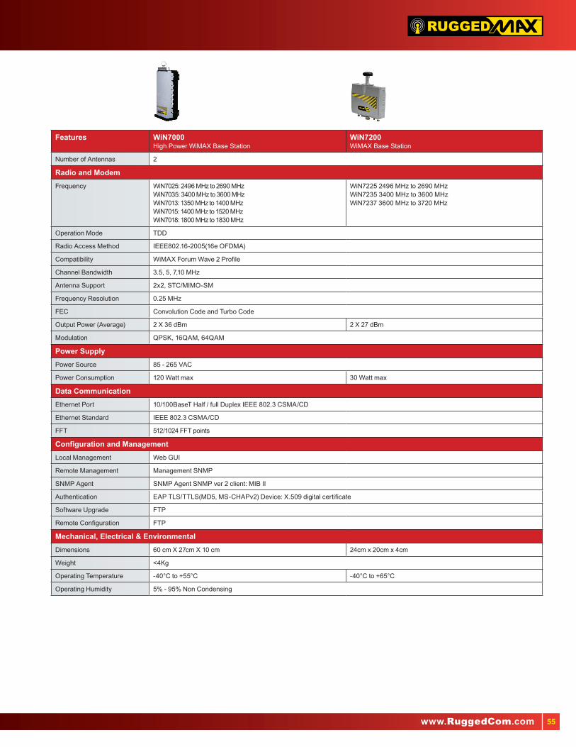
55www.RuggedCom.com
™
Features WiN7000 High Power WiMAX Base Station
WiN7200 WiMAX Base Station
Number of Antennas 2
Radio and Modem
Frequency WiN7025: 2496 MHz to 2690 MHzWiN7035: 3400 MHz to 3600 MHzWiN7013: 1350 MHz to 1400 MHzWiN7015: 1400 MHz to 1520 MHzWiN7018: 1800 MHz to 1830 MHz
WiN7225 2496 MHz to 2690 MHzWiN7235 3400 MHz to 3600 MHzWiN7237 3600 MHz to 3720 MHz
Operation Mode TDD
Radio Access Method IEEE802.16-2005(16e OFDMA)
Compatibility WiMAX Forum Wave 2 Profile
Channel Bandwidth 3.5, 5, 7,10 MHz
Antenna Support 2x2, STC/MIMO-SM
Frequency Resolution 0.25 MHz
FEC Convolution Code and Turbo Code
Output Power (Average) 2 X 36 dBm 2 X 27 dBm
Modulation QPSK, 16QAM, 64QAM
Power Supply
Power Source 85 - 265 VAC
Power Consumption 120 Watt max 30 Watt max
Data Communication
Ethernet Port 10/100BaseT Half / full Duplex IEEE 802.3 CSMA/CD
Ethernet Standard IEEE 802.3 CSMA/CD
FFT 512/1024 FFT points
Configuration and Management
Local Management Web GUI
Remote Management Management SNMP
SNMP Agent SNMP Agent SNMP ver 2 client: MIB II
Authentication EAP TLS/TTLS(MD5, MS-CHAPv2) Device: X.509 digital certificate
Software Upgrade FTP
Remote Configuration FTP
Mechanical, Electrical & Environmental
Dimensions 60 cm X 27cm X 10 cm 24cm x 20cm x 4cm
Weight <4Kg
Operating Temperature -40°C to +55°C -40°C to +65°C
Operating Humidity 5% - 95% Non Condensing

56


Rugged Communications Networking Solutions for Harsh Environments
www.RuggedCom.com
RuggedCom Inc.300 Applewood CrescentConcord, Ontario, Canada L4K 5C7
Tel: +1 (905) 856-5288 Fax: +1 (905) 482-2156 Toll Free: 1 (888) 264-0006
© 2010 RuggedCom Inc. RuggedSwitch is a trademark of RuggedCom Inc.Ethernet is a trademark of the Xerox Corporation.All specifications in this document are subject to change without notice.Rev 1g