product catalog, air-cooled scroll chillers, model cgam ... · pdf fileair-cooled scroll...
TRANSCRIPT

Air-Cooled Scroll Chillers
Model CGAM — Made in USA
20 to 130 NominalTons (60 Hz and 50 Hz)
July 2017 CG-PRC017N-EN
Product Catalog

©2017 Ingersoll Rand CG-PRC017N-EN
Introduction
Design and manufacturing excellence makesTrane a leader in the air-cooled chiller market place.This tradition of using excellence to meet market demands is illustrated with theTrane 20 to 130ton air-cooled scroll chiller.This next-generation chiller is an exciting step forward in energy-efficiency, sound, reliability, ease of serviceability, control precision, application versatility, andoperational cost-effectiveness.The chiller is designed to deliver provenTrane performance basedon the redesign of a European model that has been a market leader, plus all the benefits of newheat transfer and fan designs, as well as, low-speed, direct-drive scroll compressors.
Important Design Features and New Features
• Higher full-load and part-load energy efficiency that exceedASHRAE 90.1 and reduce operatingcosts
• Significantly lower noise levels than other scroll compressor chillers.
• R-410A optimized design.
• Flow switch and water strainer are factory installed in the optimum locations for seamlessoperation and reduced chiller installation and maintenance time.
• Tracer® CH530 with Adaptive Control™ has improved fan algorithms for more reliableoperation at extreme conditions.
• Single chiller time of day scheduling communication for easier control of small jobs.
• Easily integrated with existing BAS via BACnet® or LonTalk® communication interface.
• All major service components are close to the unit edge for safe and easy maintenance.
• The chiller is designed for easy serviceability with input from our extensive experience indesign, testing and field operation.
Copyright
This document and the information in it are the property ofTrane, and may not be used orreproduced in whole or in part without written permission.Trane reserves the right to revise thispublication at any time, and to make changes to its content without obligation to notify any personof such revision or change.
Trademarks
All trademarks referenced in this document are the trademarks of their respective owners.
Revision History
• Updated flow rates in General Data table.
• Correction to Table 15, p. 41 for 100 ton unit dimensions.
• Update AHRI back cover logo.

CG-PRC017N-EN 3
Table of Contents
Introduction . . . . . . . . . . . . . . . . . . . . . . . . . . . . . . . . . . . . . . . . . . . . . . . . . . . . . . 2
Features and Benefits . . . . . . . . . . . . . . . . . . . . . . . . . . . . . . . . . . . . . . . . . . . . . . 4
Application Considerations . . . . . . . . . . . . . . . . . . . . . . . . . . . . . . . . . . . . . . . . . . 6
Model Number Descriptions . . . . . . . . . . . . . . . . . . . . . . . . . . . . . . . . . . . . . . . . 13
General Data . . . . . . . . . . . . . . . . . . . . . . . . . . . . . . . . . . . . . . . . . . . . . . . . . . . . . 15
Controls . . . . . . . . . . . . . . . . . . . . . . . . . . . . . . . . . . . . . . . . . . . . . . . . . . . . . . . . 25
Electrical . . . . . . . . . . . . . . . . . . . . . . . . . . . . . . . . . . . . . . . . . . . . . . . . . . . . . . . . 29
Electrical Connections . . . . . . . . . . . . . . . . . . . . . . . . . . . . . . . . . . . . . . . . . . . . . 36
Dimensions . . . . . . . . . . . . . . . . . . . . . . . . . . . . . . . . . . . . . . . . . . . . . . . . . . . . . . 40
Weights . . . . . . . . . . . . . . . . . . . . . . . . . . . . . . . . . . . . . . . . . . . . . . . . . . . . . . . . . 53
Mechanical Specifications . . . . . . . . . . . . . . . . . . . . . . . . . . . . . . . . . . . . . . . . . . 60

Features and Benefits
Reliability
• Years of laboratory testing, including running the chiller at extreme operating conditions, haveresulted in optimized compressor and chiller systems reliability by confirming a robust designand verifying quality each step of the way.
• Direct-drive, low-speed scroll compressors with fewer moving parts provide maximumefficiency, high reliability, and low maintenance requirements. Suction gas-cooled motor staysat a uniformly low temperature for long motor life.
• The third generation microprocessor control system provides improved control capabilitieswith Adaptive Control™ to keep the unit operating even in adverse conditions. Advancedmicroelectronics protect both the compressor and the motor from typical electrical faultconditions like thermal overload and phase rotation.
• Standard factory-installed water strainer helps prevent system debris from affecting unit flowor heat transfer.
• Flow switch is factory-installed at the optimum location in the piping for reduced chillerinstallation cost and superior flow sensing, reducing the potential for nuisance trips.
• Microchannel condenser uses all-aluminum coils with fully-brazed construction.This designreduces risk of leaks.Their flat streamlined tubes with small ports and metallurgical tube-to-fin bond enable exceptional heat transfer and dramatic reduction in refrigerant use.
• The optional round tube and plate fin condenser with its exceptionally rigid coil structure ismanufactured with hairpin tubes which reduces the number of braze joints by half, significantlyreducing the potential for leaks.
• Innovative condenser pressure integrated fan control algorithms and variable frequency driveon circuits’ lead fans provides more reliable operation at extreme temperature conditions.
Life Cycle Cost-Effectiveness
• Industry leading full- and part-load efficiencies
• Electronic expansion valve and high speed suction temperature sensor enables tight chilledwater temperature control and low superheat, resulting in more efficient full-load and part-loadoperation than previously available.
• Partial heat recovery available to save energy on pre-heat or reheat applications.
• Optional pump package features variable speed drive on the pump motors, eliminating theneed for energy sapping chilled water system triple-duty or balancing valves. Additionally,system commissioning and flexibility is greatly enhanced. Chilled water supply reliability isincreased with the dual pump design, due to standard failure/recovery functionality.
Application Versatility
• Industrial/low temperature process cooling - Excellent operating temperature range andprecise control capabilities enable tight control.
• Ice/thermal storage - Utilities and owners benefit from reduced cooling energy cost.Thechiller’s dual setpoint control and industry leading energy storage efficiency assures reliableoperation and superior system efficiency.Trane’s partnership with CALMAC brings a proventrack record of successful installations across many markets; from churches and schools to skyscrapers and office buildings.
• Partial heat recovery -An optional factory-installed heat exchanger provides hot water for manyneeds; water preheat and reheat for enhanced system humidity control are just two.This optionreduces operating costs associated with boilers/domestic hot water.
4 CG-PRC017N-EN

Features and Benefits
Simple, Economical Installation
• Reduced sound levels, compared to other scroll compressor chillers, perfect for applyingoutdoor HVAC equipment in neighborhoods, such as K-12 schools.
• System integration available with LonTalk® or BACnet® through a single twisted-pair wire fora less expensive translation to an existing building automation system.
• Powder-coated paint provides superior durability, corrosion protection, and is less likely to bedamaged while rigging/lifting/installing the chiller.
• Factory commissioned unit-mounted starter reduces overall job cost and improves systemreliability by eliminating job site design, installation and labor coordination requirements.
Precision Control
• Easily integrated with existing BAS via BACnet® or LonTalk® communication interfaces.
• Microprocessor-basedTracer® CH530 controls monitor and maintain optimal operation of thechiller and its associated sensors, actuators, relays, and switches, all of which are factory-installed and tested prior to shipping.
• Adaptive Control maintains chiller operation under adverse conditions, when many otherchillers might simply shut down.The chiller control is able to compensate for conditions suchas high condensing pressure and low suction pressure.
• Advanced microprocessor controls enable variable primary flow applications providing chilledwater temperature control accuracy of ±2°F (1.1°C) with flow changes up to 10 percent perminute, while keeping the chiller online through flow changes up to 30 percent per minute.
• Easy-to-use operator interface displays all operating and safety messages, with completediagnostics information, on a highly readable panel with a scrolling touch-screen display.Status and diagnostic messages are in plain language - no codes to interpret - and are availablein 20 languages.
Improved Serviceability
• All major serviceable components are close to the edge. Service shutoff valves and waterstrainer are conveniently located to enable easy service.
• Water piping connections are factory piped to the edge of the unit to make installation safer andfaster.
• Electronic expansion valve designed so controls can be removed and serviced withoutrefrigerant handling.
• The optional pump package is designed to be serviced in place.The unit structure includes arigging point for pump servicing, making inspection, cleaning and pump seal changes easier.
• High pressure transducer and temperature sensors mountings enable troubleshooting andreplacement without removing refrigerant charge, greatly improving serviceability over the lifeof the unit.
• Dead front panel construction provides for enhanced service technician safety.
CG-PRC017N-EN 5

Application Considerations
Certain application constraints should be considered when sizing, selecting and installingTraneCGAM chillers. Unit and system reliability is often dependent upon proper and completecompliance with these considerations.Where the application varies from the guidelines presented,it should be reviewed with your localTrane account manager.
Note: The terms water and solution are used interchangeably in the following paragraphs.
Unit Sizing
SeeTOPSS™ performance selection software for unit capacities. Intentionally over-sizing a unit toassure adequate capacity is not recommended. Erratic system operation and excessivecompressor cycling are often a direct result of an oversized chiller. In addition, an oversized unitis usually more expensive to purchase, install, and operate. If oversizing is desired consider usingtwo smaller units.
WaterTreatment
The use of untreated or improperly treated water in chillers may result in scaling, erosion,corrosion, and algae or slime buildup.This will adversely affect heat transfer between the waterand system components. Proper water treatment must be determined locally and depends on thetype of system and local water characteristics.
Neither salt nor brackish water is recommend for use inTrane air-cooled CGAM chillers. Use ofeither will lead to a shortened life.Trane encourages employing a qualified water treatmentspecialist, familiar with local water conditions, to assist in establishing a proper water treatmentprogram.
Foreign matter in the chilled water system can also increase pressure drop and, consequently,reduce water flow. For this reason it is important to thoroughly flush all water piping to the unitbefore making the final piping connections to the unit.
Effect of Altitude on Capacity
At elevations substantially above sea level, the decreased air density will decrease condensercapacity and, therefore, unit capacity and efficiency. S
Ambient Limitations
Trane chillers are designed for year-round operation over a range of ambient temperatures.The air-cooled model CGAM chiller will operate in ambient temperatures of 32 to 125°F (0 to 52°C) for highambient or 0 to 125°F (-18 to 52°C) for wide ambient. Extreme low ambient operation is offereddown to -20°F (-28.9°C). Operation below 32°F requires the use of variable speed fans unlessotherwise specified.
The minimum ambient temperatures are based on still conditions (winds not exceeding five mph).Greater wind velocities will result in a drop in head pressure, therefore increasing the minimumstarting and operating ambient temperature.The Adaptive Control™ microprocessor will attemptto keep the chiller on-line when high or low ambient conditions exist, making every effort to avoidnuisance trip-outs and provide the maximum allowable tonnage.
6 CG-PRC017N-EN
Application Considerations
Water Flow Limits
The minimum water flow rates are given in the General Data section of this catalog. Evaporatorflow rates below the tabulated values will result in laminar flow causing freeze-up problems,scaling, stratification and poor control.The maximum evaporator water flow rate is also given.Flow rates exceeding those listed may result in very high pressure drop across the evaporator.
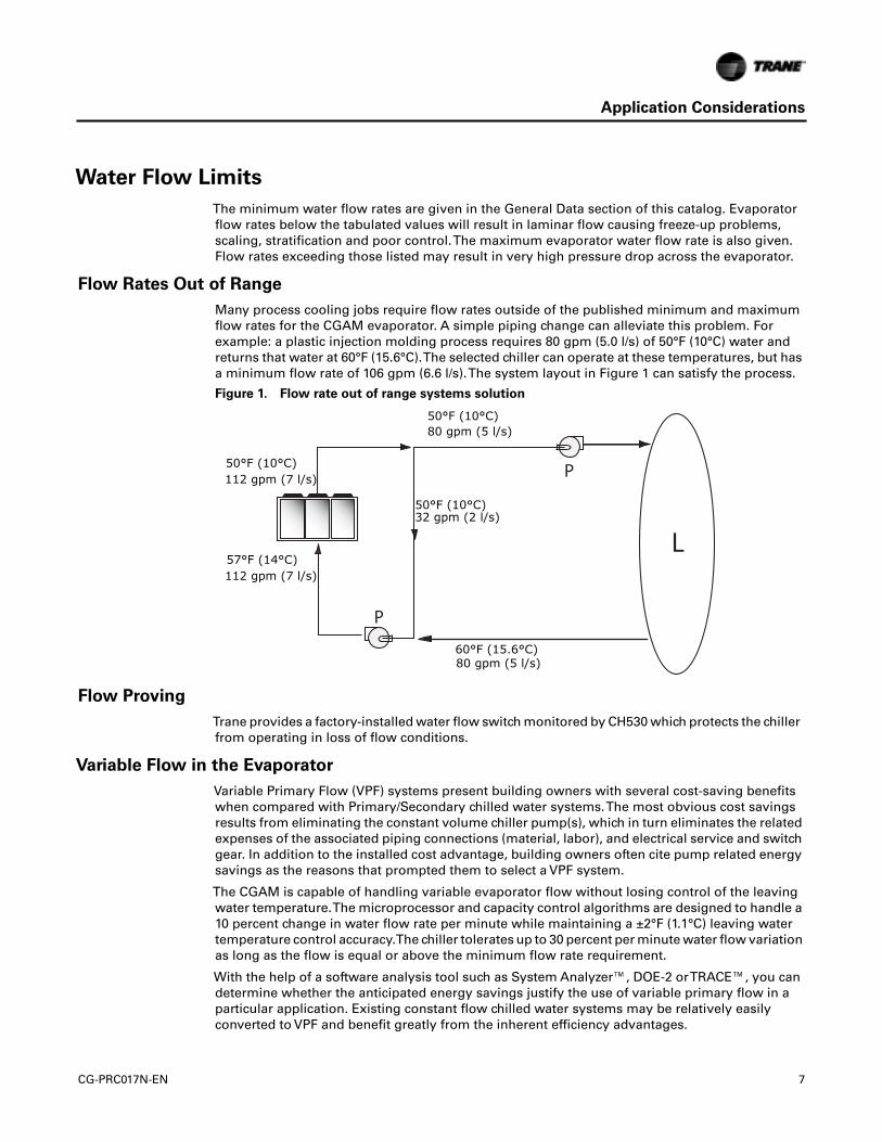
Flow Rates Out of Range
Many process cooling jobs require flow rates outside of the published minimum and maximumflow rates for the CGAM evaporator. A simple piping change can alleviate this problem. Forexample: a plastic injection molding process requires 80 gpm (5.0 l/s) of 50°F (10°C) water andreturns that water at 60°F (15.6°C).The selected chiller can operate at these temperatures, but hasa minimum flow rate of 106 gpm (6.6 l/s).The system layout in Figure 1 can satisfy the process.
Flow Proving
Trane provides a factory-installed water flow switch monitored by CH530 which protects the chillerfrom operating in loss of flow conditions.
Variable Flow in the Evaporator
Variable Primary Flow (VPF) systems present building owners with several cost-saving benefitswhen compared with Primary/Secondary chilled water systems.The most obvious cost savingsresults from eliminating the constant volume chiller pump(s), which in turn eliminates the relatedexpenses of the associated piping connections (material, labor), and electrical service and switchgear. In addition to the installed cost advantage, building owners often cite pump related energysavings as the reasons that prompted them to select a VPF system.
The CGAM is capable of handling variable evaporator flow without losing control of the leavingwater temperature.The microprocessor and capacity control algorithms are designed to handle a10 percent change in water flow rate per minute while maintaining a ±2°F (1.1°C) leaving watertemperature control accuracy.The chiller tolerates up to 30 percent per minute water flow variationas long as the flow is equal or above the minimum flow rate requirement.
With the help of a software analysis tool such as System Analyzer™, DOE-2 orTRACE™, you candetermine whether the anticipated energy savings justify the use of variable primary flow in aparticular application. Existing constant flow chilled water systems may be relatively easilyconverted to VPF and benefit greatly from the inherent efficiency advantages.
Figure 1. Flow rate out of range systems solution
50°F (10°C)112 gpm (7 l/s)
50°F (10°C)80 gpm (5 l/s)
60°F (15.6°C)80 gpm (5 l/s)
50°F (10°C)32 gpm (2 l/s)
57°F (14°C)112 gpm (7 l/s)
CG-PRC017N-EN 7

Application Considerations
WaterTemperature
Leaving WaterTemperature Limits
Trane CGAM chillers have three distinct leaving water temperature categories:
• standard, with a leaving solution range of 42 to 65°F (5.5 to 18°C)
• low temperature process cooling, with leaving solution range of 10 to 65°F (-12 to 18°C)
• ice-making, with leaving solution range of 20 to 65°F (-7 to 18°C)
• low leaving temperature, with leaving solution below 10°F (-12.2°C)
Since a leaving solution temperature below 42°F (5.5°C) results in a suction temperature at orbelow the freezing point of water, a glycol solution is required for all low temperature and ice-making machines. Ice making control includes dual setpoint controls and safeties for ice makingand standard cooling capabilities. Consult your localTrane account manager for applications orselections involving low temperature or ice making machines.
The maximum water temperature that can be circulated through the CGAM evaporator when theunit is not operating is 125°F (51.7°C). Evaporator damage may result above this temperature.
Leaving WaterTemperature Out of Range
Similar to the flow rate limitations above, many process cooling jobs require temperature rangesthat are outside the allowable minimum and maximum operating values for the chiller. Figure 2below shows a simple example of a mixed water piping arrangement change that can enablereliable chiller operation while meeting such cooling conditions. For example, a laboratory loadrequires 238 gpm (5 l/s) of water entering the process at 86°F (30°C) and returning at 95°F (35°C).The chiller’s maximum leaving chilled water temperature of 65°F (15.6°C) prevents direct supply tothe load. In the example shown, both the chiller and process flow rates are equal, however, this isnot necessary. For example, if the chiller had a higher flow rate, there would simply be more waterbypassing and mixing with warm water returning to the chiller.
Supply WaterTemperature Drop
The cataloged performance data for theTrane CGAM chiller is based on a chilled water temperaturedrop of 10°F (6°C) for I-P data and 9°F (5°C) for SI data. Full load chilled water temperature dropsfrom 6 to 18°F (3.3 to 10°C) may be used as long as minimum and maximum water temperatureand minimum and maximum flow rates are not exceeded.Temperature drops outside this range
Figure 2. Temperature out of range system solution
L
P
P
59°F (15°C) 86°F (30°C)238 gpm (15 l/s)
95°F (35°C)
178 gpm (11.2 l/s)
95°F (35°C)238 gpm (15 l/s)
95°F (35°C)60 gpm (3.8 l/s)
59°F (15°C)
178 gpm (11.2 l/s)
68°F (20°C)238 gpm (15 l/s)
60 gpm (3.8 l/s)
238 gpm (15 l/s)59°F (15°C)
8 CG-PRC017N-EN

Application Considerations
at full load conditions are beyond the optimum range for control and may adversely affect themicrocomputer’s ability to maintain an acceptable supply water temperature range. Furthermore,full load temperature drops of less than 6°F (3.3°C) may result in inadequate refrigerant superheatwhich is critical to long term efficient and reliable operation. Sufficient superheat is always aprimary concern in any refrigerant system and is especially important in a packaged chiller wherethe evaporator is closely coupled to the compressor.
Typical Water Piping
All building water piping must be flushed prior to making final connections to the chiller.To reduceheat loss and prevent condensation, insulation should be applied. Expansion tanks are also usuallyrequired so that chilled water volume changes can be accommodated.
Avoidance of Short Water Loops
Adequate water volume is an important system design parameter because it provides for stablechilled water temperature control and helps limit unacceptable short cycling of chillercompressors.
The chiller’s temperature control sensor is located in the supply (outlet) water connection or pipe.This location allows the building to act as a buffer to slow the rate of change of the system watertemperature. If there is not sufficient water volume in the system to provide an adequate buffer,temperature control can suffer, resulting in erratic system operation and excessive compressorcycling.
Typically, a two-minute water loop circulation time is sufficient to prevent short water loop issues.Therefore, as a guideline, ensure the volume of water in the chilled water loop is greater than orequal to two times the evaporator flow rate. For systems with a rapidly changing load profile thevolume should be increased.
If the installed system volume does not meet the above recommendations, the following itemsshould be given careful consideration to increase the volume of water in the system and, therefore,reduce the rate of change of the return water temperature.
• A volume buffer tank located in the return water piping.
• Larger system supply and return header piping (which also reduces system pressure drop andpump energy use).
Minimum water volume for a process application
If a chiller is attached to an on/off load such as a process load, it may be difficult for the controllerto respond quickly enough to the very rapid change in return solution temperature if the systemhas only the minimum water volume recommended. Such systems may cause chiller lowtemperature safety trips or in the extreme case evaporator freezing. In this case, it may benecessary to add or increase the size of the mixing tank in the return line.
Multiple Unit Operation
Whenever two or more units are used on one chilled water loop,Trane recommends that theiroperation be coordinated with a higher level system controller for best system efficiency andreliability.TheTraneTracer system has advanced chilled plant control capabilities designed toprovide such operation.
Ice Storage Operation
An ice storage system uses the chiller to make ice at night when utility rates are lower.The storedice reduces or even replaces mechanical cooling during the day when utility rates are at theirhighest.This reduced need for cooling results in significant utility cost savings and source energysavings.
CG-PRC017N-EN 9

Application Considerations
Another advantage of an ice storage system is its ability to eliminate chiller oversizing. A“rightsized” chiller plant with ice storage operates more efficiently with smaller support equipmentwhile lowering the connected load and reducing operating costs. Best of all, this system stillprovides a capacity safety factor and redundancy by building it into the ice storage capacity forpractically no cost compared to oversized systems.
Trane air-cooled chillers are uniquely suited to low temperature applications like ice storagebecause of the ambient relief experienced at night. Chiller ice making efficiencies are typicallysimilar to or even better than standard cooling daytime efficiencies as a result of nighttime dry-bulbambient relief.
Standard smart control strategies for ice storage systems are another advantage of the CGAMchiller.The dual mode control functionality is integrated right into the chiller.TraneTracer buildingmanagement systems can measure demand and receive pricing signals from the utility and decidewhen to use the stored cooling and when to use the chiller.
Partial Heat Recovery Operation
Partial heat recovery is designed to capture a portion of the heat that is normally rejected to theatmosphere and put it to beneficial use. With the addition of a heat recovery cycle, heat removedfrom the building cooling load can be transferred to a preheat application. Keep in mind that theheat recovery cycle is only possible if a cooling load exists to act as a heat source.
To provide a heat recovery cycle, a supplemental heat exchanger is mounted in series to the air-cooled condenser.The supplemental heat exchanger is piped into a preheat circuit. During the heatrecovery cycle, the unit operates just as it does in the cooling-only mode except that a portion ofthe cooling load heat is rejected to the water heating circuit rather than to the air through the air-cooled condenser. Water circulated through the heat recovery heat exchanger by the pumpsabsorbs cooling load heat from the compressed refrigerant gas discharged by the compressors.The heated water is then used to satisfy heating requirements.
Partial heat recovery can be used in applications where hot water is needed for use in kitchens,lavatories, etc. It is comparatively smaller in size and its heating capacity is not controlled.Thepartial heat recovery heat exchanger cannot operate alone without a load on the chiller.
The partial heat recovery heat exchanger can get up to 157°F (69.4°C) leaving temperature. Formore information seeTOPSS™ performance selection program.
Unit Placement
SettingThe Unit
A base or foundation is not required if the selected location is level and strong enough to supportthe unit’s operating weight (see “Weights” section of this catalog).
For a detailed discussion of base and foundation construction, refer to the sound engineeringbulletin or the unit IOM. Manuals are available through the localTrane office.
HVAC equipment must be located to minimize sound and vibration transmission to the occupiedspaces of the building structure it serves. If the equipment must be located in close proximity toa building, it should be placed next to an unoccupied space such as a storage room, mechanicalroom, etc. It is not recommended to locate the equipment near occupied, sound sensitive areas ofthe building or near windows. Locating the equipment away from structures will also preventsound reflection, which can increase sound levels at property lines or other sensitive points.
10 CG-PRC017N-EN

Application Considerations
Isolation and Sound Emission
Structurally transmitted sound can be reduced by elastomeric vibration eliminators. Elastomericisolators are generally effective in reducing vibratory noise generated by compressors, andtherefore, are recommended for sound sensitive installations. An acoustical engineer shouldalways be consulted on critical applications.
For maximum isolation effect, water lines and electrical conduit should also be isolated. Wallsleeves and rubber isolated piping hangers can be used to reduce the sound transmitted throughwater piping.To reduce the sound transmitted through electrical conduit, use flexible electricalconduit.
Local codes on sound emissions should always be considered. Since the environment in which asound source is located affects sound pressure, unit placement must be carefully evaluated. Soundpower levels for chillers are available on request.
Servicing
Adequate clearance for evaporator and compressor servicing should be provided. Recommendedminimum space envelopes for servicing are located in the dimensional data section and can serveas a guideline for providing adequate clearance.The minimum space envelopes also allow forcontrol panel door swing and routine maintenance requirements. Local code requirements maytake precedence.
Figure 3. Installation example
Flexible electricalconduit
Chilled water piping
Isolators
Piping isolation
Concrete base
Isolators
supported.should be
CG-PRC017N-EN 11

Application Considerations
Unit Location
General
Unobstructed flow of condenser air is essential to maintain chiller capacity and operatingefficiency. When determining unit placement, careful consideration must be given to assure asufficient flow of air across the condenser heat transfer surface.Two detrimental conditions arepossible and must be avoided: warm air recirculation and coil starvation. Air recirculation occurswhen discharge air from the condenser fans is recycled back to the condenser coil inlet. Coilstarvation occurs when free airflow to the condenser is restricted.
Condenser coils and fan discharge must be kept free of snow or other obstructions to permitadequate airflow for satisfactory unit operation. Debris, trash, supplies, etc., should not be allowedto accumulate in the vicinity of the air-cooled chiller. Supply air movement may draw debris intothe condenser coil, blocking spaces between coil fins and causing coil starvation.
Both warm air recirculation and coil starvation cause reductions in unit efficiency and capacitybecause of the higher head pressures associated with them.The air-cooled CGAM chiller offers anadvantage over competitive equipment in these situations. Operation is minimally affected inmany restricted air flow situations due to its advanced Adaptive Control™ microprocessor whichhas the ability to understand the operating environment of the chiller and adapt to it by firstoptimizing its performance and then staying on line through abnormal conditions. For example,high ambient temperatures combined with a restricted air flow situation will generally not causethe air-cooled model CGAM chiller to shut down. Other chillers would typically shut down on a highpressure nuisance cut-out in these conditions.
Cross winds, those perpendicular to the condenser, tend to aid efficient operation in warmerambient conditions. However, they tend to be detrimental to operation in lower ambients due tothe accompanying loss of adequate head pressure. Special consideration should be given to lowambient units. As a result, it is advisable to protect air-cooled chillers from continuous direct windsexceeding 10 mph (4.5 m/s) in low ambient conditions.
The recommended lateral clearances are depicted in the close spacing engineering bulletinavailable from your local office.
Provide Sufficient Unit-to-Unit Clearance
Units should be separated from each other by sufficient distance to prevent warm air recirculationor coil starvation. Doubling the recommended single unit air-cooled chiller clearances willgenerally prove to be adequate.
Walled Enclosure Installations
When the unit is placed in an enclosure or small depression, the top of the surrounding wallsshould be no higher than the top of the fans.The chiller should be completely open above the fandeck.There should be no roof or structure covering the top of the chiller. Ducting individual fansis not recommended.
12 CG-PRC017N-EN

Model Number Descriptions
Digits 1-4— Chiller ModelCGAM= Air-Cooled Scroll Packaged
Chiller
Digits 5-7— Unit NominalTon020 = 20Tons026 = 26Tons030 = 30Tons035 = 35Tons040 = 40Tons052 = 52Tons060 = 60Tons070 = 70Tons080 = 80Tons090 = 90Tons100 = 100Tons110 = 110Tons120 = 120Tons130 = 130Tons
Digit 8— Unit VoltageA = 208 Volt 60 Hz 3 PhaseB = 230 Volt 60 Hz 3 PhaseD = 380 Volt 60 Hz 3 PhaseE = 400 Volt 50 Hz 3 PhaseF = 460 Volt 60 Hz 3 PhaseG = 575 Volt 60 Hz 3 Phase
Digit 9— Manufacturing Plant2 = Pueblo, USA
Digits 10-11— Design Sequence** = Factory/ABU Assigned
Digit 12— UnitType2 = High Efficiency3 = Extra Efficiency
Digit 13— Agency ListingX = No Agency ListingA = UL Listed to U.S. and
Canadian Safety Standard
Digit 14— Pressure Vessel CodeX = No Pressure Vessel Code
Digit 15— Unit ApplicationB = High Ambient (32-125°F/0-52°C)D = Wide Ambient
(0-125°F/-18-52°C)J = Extreme Low Ambient —
down to -20°F (-28.9°C)
Digit 16— Refrigerant IsolationValves2 = Refrigerant Isolation Valves
(Discharge Valve)
Digit 17— Structural OptionsA = Standard Unit StructureB = Seismic to International Building
Code (IBC)C = California Office of Statewide
Health Planning andDevelopment (OSHPD)Certification
D = Wind Load for Florida Hurricane
CG-PRC017N-EN
Digit 18— Freeze Protection(Factor-Installed Only)X = Without Freeze Protection1 = With Freeze Protection
(ExternalT-Stat Control)
Digit 19— InsulationA = Factory Insulation - All Cold PartsB = Insulation for High Humidity/
Low EvapTemp
Digit 20— Factory Charge1 = Full Factory Refrigerant Charge
(R-410A)2 = Nitrogen Charge
Digit 21— EvaporatorApplicationA = Standard Cooling
(42 to 65°F/5.5 to 18°C)B = LowTemperature Process
(10 to 42°F/-12.2 to 5.5°C)C = Ice-Making - Hardwired Interface
(20 to 65°F/-7 to 18°C)D = Low Leaving Water
(below 10°F/-12.2°C)
Digit 22— Water Connections1 = Grooved Pipe Connection
Digit 23— Condenser FinMaterialA = Lanced Aluminum FinsC = Non-Lanced Copper FinsD = Lanced Aluminum Fins
w/ CompleteCoat™H = Microchannel CoilsJ = Microchannel Coils
w/ CompleteCoat
Digit 24— Condenser HeatRecoveryX = No Heat Recovery1 = Partial Heat Recovery with
Fan Control
Digit 25— Not UsedX
Digit 26— StarterTypeA = Across the Line Starter/
Direct on Line
Digit 27— Incoming Power LineConnection1 = Single Point Power Connection
Digit 28— Power LineConnectionTypeA = Terminal BlockC = Circuit BreakerD = Circuit Breaker with High Fault
Rated Control Panel
Digit 29— EnclosureType1 = WaterTight (per UL 1995
Standard)
Digit 30— Unit OperatorInterfaceA = Dyna-View/English
Digit 31— Remote Interface(Digital Comm)X = No Remote Digital
Communication2 = LonTalk®/Tracer® Summit
Interface3 = Time of Day Scheduling4 = BACNet® Interface
Digit 32— External Chilled/HotWater and Current Demand LimitSetpointX = No External Chilled Water
SetpointA = External Chilled Water and
Demand Limit Setpoint 4-20mAB = External Chilled Water and
Demand Limit Setpoint 2-10Vdc
Digit 33— Percent CapacityX = Without % Capacity1 = With % Capacity
Digit 34— Programmable RelaysX = No Programmable RelaysA = Programmable Relays
Digit 35— PumpTypeX = No Pumps and No Contactors8 = Dual High Head Pump
Digit 36— Pump Flow ControlX = No Pump ControlB = Pump Flow Controlled by
Variable Speed Drive
Digit 37 — BufferTankX
Digit 38— Short Circuit RatingX = No Short Circuit RatingA = Default A Short Circuit RatingB = High A Short Circuit Rating
Digit 39— InstallationAccessoriesX = No Installation Accessories1 = Elastomeric Isolators3 = Seismically Rated Isolators5 = Elastomeric Pads
Digit 40— Water StrainerA = With Water Strainer Factory
Installed
Digit 41— Sound AttenuatorPackage3 = Super Quiet5 = Comprehensive Acoustic
Package
13

Model Number Descriptions
Digit 42— Appearance OptionsX = No Appearance OptionsA = Architectural Louvered PanelsB = Half Louvers
Digit 43— Exterior Finish1 = Standard Paint
Digit 44— Label, LiteratureLanguageB = Spanish and EnglishD = EnglishE = French and English
Digit 45— Phase ReversalProtection1 = Phase Reversal Protection
Digit 46— Shipping PackageX = No Skid (Standard)A = Unit Containerization Package
Digit 47— PerformanceTestOptionsX = No PerformanceTest2 = Test with Report3 = WitnessTest with Report
Digit 48— Flow Switch Set PointC = Flow Switch Set Point 15F = Flow Switch Set Point 35H = Flow Switch Set Point 45L = Flow Switch Set Point 60
Digit 49— Not UsedX
Digit 50— SpecialsX = NoneS = Special
Note: If a digit is not defined it may beheld for future use.
14
CG-PRC017N-EN
General Data
Table 1. General data, 60 Hz, high efficiency (I-P)
Size 20 26 30 35 40 52 60 70 80 90 100 110 120 130
Compressor
Number # 2 2 2 2 4 4 4 4 4 4 4 4 4 6
Tonnage/ckt(a) 10+10 13+13 15+15 15+20 10+10 13+13 15+15 15+20 20+20 20+25 25+25 25+30 30+30 20+20+25
Evaporator
Water storage (gal) 1.4 2.2 2.2 3.2 2.4 4.1 5.0 7.5 7.0 9.0 10.3 11.5 11.5 12.3
Min. flow (LWT ≥42°F) (gpm) 23.2 29.8 33.1 39.2 45.4 58.8 67.1 79.5 91.8 102.6 115.5 125.2 135.9 146.9
Min. flow (LWT 40 to 41.9°F) (gpm) 29.1 37.2 41.8 49.1 56.7 73.5 83.9 99.4 114.7 128.3 144.4 156.5 169.9 183.7
Max. flow (gpm) 69 89 100 117 136 176 201 238 275 307 346 375 407 440
Water connection (in) 2 2.5 2.5 2.5 3 3 3 3 4 4 4 4 4 4
Condenser
Round Tube and Plate Fin Coils
Quantity of coils # 1 1 1 1 2 2 2 2 4 4 4 4 4 4
Coil length (in) 91 91 127 127 91 91 127 127 121 121 144 144 144 180
Coil height (in) 68 68 68 68 68 68 68 68 42 42 42 42 42 42
Number of rows # 2 2 2 2 2 2 2 2 3 3 3 3 3 3
Fins per foot (fpf) 192 192 192 192 192 192 192 192 192 192 192 192 192 192
Microchannel Coils
Quantity of coils # 1 1 1 1 2 2 2 2 8 8 8 8 8 8
Coil length (in) 91 91 127 127 91 91 127 127 68+46 68+46 68+68 68+68 68+68 68+104
Coil height(b) (in) 42+10 42+10 42+10 42+10 42+10 42+10 42+10 42+10 34+7 34+7 34+7 34+7 34+7 34+7
Tube width (in) 1 1 1 1 1 1 1 1 1 1 1 1 1 1
Fan
Quantity # 2 2 3 3 4 4 6 6 6 6 8 8 8 10
Diameter (in) 28.8 28.8 28.8 28.8 28.8 28.8 28.8 28.8 28.8 28.8 28.8 28.8 28.8 28.8
Airflow per fan (cfm) 9413 9420 9168 9173 9413 9420 9168 9173 9470 9472 9094 9096 9098 9094
Power per motor (HP) 1.3 1.3 1.3 1.3 1.3 1.3 1.3 1.3 1.3 1.3 1.3 1.3 1.3 1.3
Motor RPM (rpm) 840 840 840 840 840 840 840 840 840 840 840 840 840 840
Tip speed (ft/min) 6333 6333 6333 6333 6333 6333 6333 6333 6333 6333 6333 6333 6333 6333
General Unit
Refrig circuits # 1 1 1 1 2 2 2 2 2 2 2 2 2 2
Capacity steps % 50-100 50-100 50-100 43-100 25-50-75-100
25-50-75-100
25-50-75-100
21-43-71-100
25-50-75-100
22-44-72-100
25-50-75-100
23-45-73-100
25-50-75-100
15-31-46-62-81-100
Min ambient - wide (°F) 0 0 0 0 0 0 0 0 0 0 0 0 0 0
Min ambient - high (°F) 32 32 32 32 32 32 32 32 32 32 32 32 32 32
Min ambient - extreme low (°F) -20 -20 -20 -20 -20 -20 -20 -20 -20 -20 -20 -20 -20 -20
CG-PRC017N-EN 15

General Data
Round Tube and Plate Fin Coils
Refrig charge/ckt(a) (lbs) 32 34 44 48 32 32 44 48 74 78 90 86 86 112
Oil charge/ckt(a) (gal) 1.7 1.7 1.9 3.5 1.7 1.7 1.9 3.5 3.5 3.5 3.5 3.7 3.8 5.8
Microchannel Coils
Refrig charge/ckt (a) (lbs) 19 22.5 28 35 19 20.5 28 35.5 45 47 49 46 50 66
Oil charge/ckt(a) (gal) 1.4 1.4 1.6 2.9 1.4 1.4 1.6 2.9 2.9 2.9 2.9 3.0 3.1 5.4
Pump Package
Avail head pressure(c) (ft H2O) 78.2 77.7 71.1 67.6 67.1 58.6 76.7 63.5 82.0 78.1 69.0 61.9 71.3 62.2
Power (HP) 5 5 5 5 5 5 7.5 7.5 10 10 10 10 15 15
Expansion tank volume (gal) 5 5 5 5 5 5 5 5 6 6 6 6 6 6
Buffer tank volume (gal) 140 140 140 140 140 140 140 140 152 152 195 195 195 195
Partial Heat Recovery
Water storage/ckt(a) (gal) 0.02 0.02 0.02 0.03 0.02 0.02 0.02 0.03 0.03 0.04 0.04 0.04 0.06 0.06
Max flow (gpm) 39 39 39 39 78 78 78 78 127 127 127 127 127 127
Water connection (in) 1.5 1.5 1.5 1.5 1.5 1.5 1.5 1.5 2.5 2.5 2.5 2.5 2.5 2.5
(a) Data shown for one circuit only. The second circuit always matches.(b) Microchannel coils are split horizontally between the condenser and subcooler coil.(c) Pump available head pressure is based on 44/54°F evaporator with water, .0001 hr-ft2-°F/Btu, 95°F ambient and 0 ft elevation.
Table 1. General data, 60 Hz, high efficiency (I-P) (continued)
Size 20 26 30 35 40 52 60 70 80 90 100 110 120 130
16 CG-PRC017N-EN

General Data
Table 2. General data, 60 Hz, high efficiency (SI)
Size 20 26 30 35 40 52 60 70 80 90 100 110 120 130
Compressor
Number # 2 2 2 2 4 4 4 4 4 4 4 4 4 6
Tonnage/ckt(a) 10+10 13+13 15+15 15+20 10+10 13+13 15+15 15+20 20+20 20+25 25+25 25+30 30+30 20+20+25
Evaporator
Water storage (l) 5.3 8.3 8.3 12.1 9.1 15.5 18.9 28.4 26.5 34.1 39.0 43.5 43.5 46.6
Min. flow (LWT ≥5.56°C) (l/s) 1.5 1.9 2.1 2.5 2.9 3.7 4.2 5.0 5.8 6.5 7.3 7.9 8.6 9.3
Min. flow (LWT 4.44 to 5.55°C) (l/s) 1.8 2.3 2.6 3.1 3.6 4.6 5.3 6.3 7.2 8.1 9.1 9.9 10.7 11.6
Max. flow (l/s) 4.4 5.6 6.3 7.4 8.6 11.1 12.7 15.1 17.4 19.4 21.9 23.7 25.7 27.8
Water connection (mm) 50.8 63.5 63.5 63.5 76.2 76.2 76.2 76.2 101.6 101.6 101.6 101.6 101.6 101.6
Condenser
Round Tube and Plate Fin Coils
Qty of coils # 1 1 1 1 2 2 2 2 4 4 4 4 4 4
Coil length (mm) 2311 2311 3226 3226 2311 2311 3226 3226 3073 3073 3658 3658 3658 4572
Coil height (mm) 1727 1727 1727 1727 1727 1727 1727 1727 1067 1067 1067 1067 1067 1067
Number of rows # 2 2 2 2 2 2 2 2 3 3 3 3 3 3
Fins per foot (fpf) 192 192 192 192 192 192 192 192 192 192 192 192 192 192
Microchannel Coils
Quantity of coils # 1 1 1 1 2 2 2 2 8 8 8 8 8 8
Coil length (mm) 2311 2311 3226 3226 2311 2311 3226 3226 1727+1168
1727+1168
1727+1727
1727+1727
1727+1727
1727+2642
Coil height(b) (mm) 1067+254
1067+254
1067+254
1067+254
1067+254
1067+254
1067+254
1067+254
864+178
864+178
864+178
864+178
864+178
864+178
Tube width (mm) 25.4 25.4 25.4 25.4 25.4 25.4 25.4 25.4 25.4 25.4 25.4 25.4 25.4 25.4
Fan
Quantity # 2 2 3 3 4 4 6 6 4 6 8 8 8 10
Diameter (mm) 732 732 732 732 732 732 732 732 732 732 732 732 732 732
Airflow per fan (m³/h) 15993 16005 15577 15585 15993 16005 15577 15585 16090 16093 15451 15454 15458 15451
Power per motor (HP) 1.3 1.3 1.3 1.3 1.3 1.3 1.3 1.3 1.3 1.3 1.3 1.3 1.3 1.3
Motor RPM (rpm) 840 840 840 840 840 840 840 840 840 840 840 840 840 840
Tip speed (m/s) 32 32 32 32 32 32 32 32 32 32 32 32 32 32
General Unit
Refrig circuits # 1 1 1 1 2 2 2 2 2 2 2 2 2 2
Capacity steps % 50-100 50-100 50-100 43-100 25-50-75-100
25-50-75-100
25-50-75-100
21-43-71-100
25-50-75-100
22-44-72-100
25-50-75-100
23-45-73-100
25-50-75-100
15-31-46-62-81-100
Min ambient - wide (°C) -18 -18 -18 -18 -18 -18 -18 -18 -18 -18 -18 -18 -18 -18
Min ambient - high (°C) 0 0 0 0 0 0 0 0 0 0 0 0 0 0
Min ambient - extreme low (°C) -28.9 -28.9 -28.9 -28.9 -28.9 -28.9 -28.9 -28.9 -28.9 -28.9 -28.9 -28.9 -28.9 -28.9
CG-PRC017N-EN 17

General Data
Round Tube and Plate Fin Coils
Refrig charge/ckt(a) (kg) 14.5 15.4 20 21.8 14.5 14.5 20 21.8 33.6 35.4 40.8 39 39 50.8
Oil charge /ckt(a) (l) 6.6 6.6 7.2 13.4 6.6 6.6 7.2 13.4 13.4 13.4 13.4 13.9 14.4 22.0
Microchannel Coils
Refrig charge/ckt(a) (kg) 8.6 10.2 12.7 15.9 8.6 9.3 12.7 16.1 20.4 21.3 22.2 20.9 22.7 29.9
Oil charge /ckt(a) (l) 5.4 5.4 5.9 11.0 5.4 5.4 5.9 11.0 11.0 11.0 11.0 11.4 11.8 18.0
Pump Package
Avail head pressure(c) (kPa) 233.7 232.3 212.6 202.1 200.6 175.0 229.2 189.7 245.1 233.3 206.3 185.0 213.1 185.8
Power (HP) 5 5 5 5 5 5 7.5 7.5 10 10 10 10 15 15
Expansion tank volume (l) 18.9 18.9 18.9 18.9 18.9 18.9 18.9 18.9 22.7 22.7 22.7 22.7 22.7 22.7
Buffer tank volume (l) 530 530 530 530 530 530 530 530 575 575 727 727 727 727
Partial Heat Recovery
Water storage/ckt(a) (l) 0.07 0.09 0.09 0.11 0.07 0.09 0.09 0.11 0.12 0.16 0.16 0.16 0.21 0.21
Max flow (l/s) 2.5 2.5 2.5 2.5 5.0 5.0 5.0 5.0 8.0 8.0 8.0 8.0 8.0 8.0
Water connection (mm) 38.1 38.1 38.1 38.1 38.1 38.1 38.1 38.1 63.5 63.5 63.5 63.5 63.5 63.5
(a) Data shown for one circuit only. The second circuit always matches.(b) Microchannel coils are split horizontally between the condenser and subcooler coil.(c) Pump available head pressure is based on 6.7/12.2°C evaporator with water, .01761 m²°C/kW, 35°C ambient and 0 m elevation.
Table 2. General data, 60 Hz, high efficiency (SI) (continued)
Size 20 26 30 35 40 52 60 70 80 90 100 110 120 130
18 CG-PRC017N-EN

General Data
Table 3. General data, 50 Hz, high efficiency (I-P)
Size 20 26 30 35 40 52 60 70 80 90 100 110 120Compressor
Number # 2 2 2 2 4 4 4 4 4 4 4 4 4Tonnage/ckt(a) 10+10 13+13 15+15 15+20 10+10 13+13 15+15 15+20 20+20 20+25 25+25 25+30 30+30
EvaporatorWater storage (gal) 1.4 2.2 2.2 3.2 2.4 4.1 5.0 7.5 7.0 9.0 10.3 11.5 11.5
Min. flow (LWT ≥42°F) (gpm) 19.7 25.1 28.2 32.7 38.1 49.4 56.4 66.0 77.5 86.8 98.0 105.8 113.1
Min. flow (LWT 40 to 41.9°F) (gpm) 24.6 31.3 35.3 40.9 47.7 61.8 70.5 82.5 96.9 108.5 122.5 132.3 141.4
Max. flow (gpm) 59 75 85 98 115 149 170 199 234 262 296 319 341Water connection (in) 2 2.5 2.5 2.5 3 3 3 3 4 4 4 4 4
CondenserRound Tube and Plate Fin Coils
Quantity of coils # 1 1 1 1 2 2 2 2 4 4 4 4 4Coil length (in) 91 91 127 127 91 91 127 127 121 121 144 144 144Coil height (in) 68 68 68 68 68 68 68 68 42 42 42 42 42
Number of rows # 2 2 2 2 2 2 2 2 3 3 3 3 3Fins per foot (fpf) 192 192 192 192 192 192 192 192 192 192 192 192 192
Microchannel CoilsQuantity of coils # 1 1 1 1 2 2 2 2 8 8 8 8 8
Coil length (in) 91 91 127 127 91 91 127 127 68+46 68+46 68+68 68+68 68+68Coil height(b) (in) 42+10 42+10 42+10 42+10 42+10 42+10 42+10 42+10 34+7 34+7 34+7 34+7 34+7
Tube width (in) 1 1 1 1 1 1 1 1 1 1 1 1 1Fan
Quantity # 2 2 3 3 4 4 6 6 6 6 8 8 8Diameter (in) 28.8 28.8 28.8 28.8 28.8 28.8 28.8 28.8 28.8 28.8 28.8 28.8 28.8
Airflow per fan (cfm) 7796 7783 7587 7590 7795 7801 7587 7590 7827 7829 7503 7505 7506Power per motor (HP) 1.3 1.3 1.3 1.3 1.3 1.3 1.3 1.3 1.3 1.3 1.3 1.3 1.3
Motor RPM (rpm) 700 700 700 700 700 700 700 700 700 700 700 700 700
Tip speed (ft/min) 5278 5278 5278 5278 5278 5278 5278 5278 5278 5278 5278 5278 5278
General UnitRefrig circuits # 1 1 1 1 2 2 2 2 2 2 2 2 2
Capacity steps % 50-100 50-100 50-100 43-100 25-50-75-100
25-50-75-100
25-50-75-100
21-43-71-100
25-50-75-100
22-44-72-100
25-50-75-100
23-45-73-100
25-50-75-100
Min ambient - wide (°F) 0 0 0 0 0 0 0 0 0 0 0 0 0Min ambient - high (°F) 32 32 32 32 32 32 32 32 32 32 32 32 32
Round Tube and Plate Fin CoilsRefrig charge/ckt(a) (lbs) 32 34 44 48 32 32 44 48 74 78 90 86 86
Oil charge/ckt(a) (gal) 1.7 1.7 1.9 3.5 1.7 1.7 1.9 3.5 3.5 3.5 3.5 3.7 3.8Microchannel Coils
Refrig charge/ckt(a) (lbs) 19 22.5 28 35 19 20.5 28 35.5 45 47 49 46 50Oil charge/ckt(a) (gal) 1.4 1.4 1.6 2.9 1.4 1.4 1.6 2.9 2.9 2.9 2.9 3.0 3.1
Partial Heat RecoveryWater storage/ckt(a) (gal) 0.02 0.02 0.02 .02 0.02 0.02 0.02 0.02 0.03 0.03 0.03 0.04 0.04
Max flow (gpm) 39 39 39 39 78 78 78 78 127 127 127 127 127Water connection (in) 1.5 1.5 1.5 1.5 1.5 1.5 1.5 1.5 2.5 2.5 2.5 2.5 2.5
(a) Data shown for one circuit only. The second circuit always matches.(b) Microchannel coils are split horizontally between the condenser and subcooler coil.
CG-PRC017N-EN 19

General Data
Table 4. General data, 50 Hz, high efficiency (SI)
Size 20 26 30 35 40 52 60 70 80 90 100 110 120Compressor
Number # 2 2 2 2 4 4 4 4 4 4 4 4 4Tonnage/ckt(a) 10+10 13+13 15+15 15+20 10+10 13+13 15+15 15+20 20+20 20+25 25+25 25+30 30+30
EvaporatorWater storage (l) 5.3 8.3 8.3 12.1 9.1 15.5 18.9 28.4 26.5 34.1 39.0 43.5 43.5
Min. flow (LWT ≥5.56°C) (l/s) 1.2 1.6 1.8 2.1 2.4 3.1 3.6 4.2 4.9 5.5 6.2 6.7 7.1
Min. flow (LWT 4.44 to 5.55°C) (l/s) 1.6 2.0 2.2 2.6 3.0 3.9 4.4 5.2 6.1 6.8 7.7 8.3 8.9
Max. flow (l/s) 3.7 4.8 5.4 6.2 7.3 9.4 10.8 12.6 14.8 16.5 18.7 20.2 21.6Water connection (mm) 50.8 63.5 63.5 63.5 76.2 76.2 76.2 76.2 101.6 101.6 101.6 101.6 101.6
CondenserRound Tube and Plate Fin Coils
Quantity of coils # 1 1 1 1 2 2 2 2 4 4 4 4 4Coil length (mm) 2311 2311 3226 3226 2311 2311 3226 3226 3073 3073 3658 3658 3658Coil height (mm) 1727 1727 1727 1727 1727 1727 1727 1727 1067 1067 1067 1067 1067
Number of rows # 2 2 2 2 2 2 2 2 3 3 3 3 3Fins per foot (fpf) 192 192 192 192 192 192 192 192 192 192 192 192 192
Microchannel CoilsQuantity of coils # 1 1 1 1 2 2 2 2 8 8 8 8 8
Coil length (mm) 2311 2311 3226 3226 2311 2311 3226 3226 1727+1168
1727+1168
1727+1727
1727+1727
1727+1727
Coil height(b) (mm) 1067+254
1067+254
1067+ 254
1067+254
1067+254
1067+254
1067+254
1067+254
864+178
864+178
864+178
864+178
864+178
Tube width (mm) 25.4 25.4 25.4 25.4 25.4 25.4 25.4 25.4 25.4 25.4 25.4 25.4 25.4Fan
Quantity # 2 2 3 3 4 4 6 6 6 6 8 8 8Diameter (mm) 732 732 732 732 732 732 732 732 732 732 732 732 732
Airflow per fan (m3/h) 13245 13223 12890 12895 13244 13254 12890 12895 13298 13302 12748 12751 12753
Power per motor (HP) 1.3 1.3 1.3 1.3 1.3 1.3 1.3 1.3 1.3 1.3 1.3 1.3 1.3Motor RPM (rpm) 700 700 700 700 700 700 700 700 700 700 700 700 700Tip speed (m/s) 26.8 26.8 26.8 26.8 26.8 26.8 26.8 26.8 26.8 26.8 26.8 26.8 26.8
General UnitRefrig circuits # 1 1 1 1 2 2 2 2 2 2 2 2 2
Capacity steps % 50-100 50-100 50-100 43-100 25-50-75-100
25-50-75-100
25-50-75-100
21-43-71-100
25-50-75-100
22-44-72-100
25-50-75-100
23-45-73-100
25-50-75-100
Min ambient - wide (°C) -18 -18 -18 -18 -18 -18 -18 -18 -18 -18 -18 -18 -18Min ambient - high (°C) 0 0 0 0 0 0 0 0 0 0 0 0 0
Round Tube and Plate Fin CoilsRefrig charge/ckt(a) (kg) 14.5 15.4 20 21.8 14.5 14.5 20 21.8 33.6 35.4 40.8 39 39
Oil charge/ckt(a) (l) 6.6 6.6 7.2 13.4 6.6 6.6 7.2 13.4 13.4 13.4 13.4 13.9 14.4Microchannel Coils
Refrig charge/ckt(a) (kg) 8.6 10.2 12.7 15.9 8.6 9.3 12.7 16.1 20.4 21.3 22.2 20.9 22.7Oil charge/ckt(a) (l) 5.4 5.4 5.9 11.0 5.4 5.4 5.9 11.0 11.0 11.0 11.0 11.4 11.8
Partial Heat RecoveryWater storage/ckt(a) (l) 0.07 0.07 0.09 0.09 0.07 0.07 0.09 0.09 0.12 0.12 0.12 0.16 0.16
Max flow (l/s) 2.5 2.5 2.5 2.5 5.0 5.0 5.0 5.0 8.0 8.0 8.0 8.0 8.0Water connection (mm) 38.1 38.1 38.1 38.1 38.1 38.1 38.1 38.1 63.5 63.5 63.5 63.5 63.5
(a) Data shown for one circuit only. The second circuit always matches.(b) Microchannel coils are split horizontally between the condenser and subcooler coil.
20 CG-PRC017N-EN

General Data
Table 5. General data, 60 Hz, extra efficiency (I-P)
Size 20 26 30 35 40 52 60 70 110 120Compressor
Number # 2 2 2 2 4 4 4 4 4 4
Tonnage/ckt(a) 10+10 13+13 15+15 15+20 10+10 13+13 15+15 15+20 25+30 30+30
EvaporatorWater storage (gal) 1.4 2.2 2.2 3.2 2.4 4.1 5.0 7.5 11.5 11.5
Min. flow (LWT ≥42°F) (gpm) 23.2 29.8 33.1 39.2 45.4 58.8 67.1 79.5 125.2 135.9
Min. flow (LWT 40 to 41.9°F) (gpm) 29.1 37.2 41.8 49.1 56.7 73.5 83.9 99.4 156.5 169.9
Max. flow (gpm) 69 89 100 117 136 176 201 238 375 407
Water connection (in) 2 2.5 2.5 2.5 3 3 3 3 4 4
CondenserRound Tube and Plate Fin Coils
Quantity of coils # 1 1 1 1 2 2 2 2 4 4
Coil length (in) 91 91 127 127 91 91 127 127 144 144
Coil height (in) 68 68 68 68 68 68 68 68 42 42
Number of rows # 3 3 3 3 3 3 3 3 3 3
Fins per foot (fpf) 192 192 192 192 192 192 192 192 192 192
FanQuantity # 2 2 3 3 4 4 6 6 8 8
Diameter (in) 28.8 28.8 28.8 28.8 28.8 28.8 28.8 28.8 28.8 28.8
Airflow per fan (cfm) 9413 9420 9168 9173 9413 9420 9168 9173 9096 9098
Power per motor (HP) 1.3 1.3 1.3 1.3 1.3 1.3 1.3 1.3 1.3 1.3
Motor RPM (rpm) 840 840 840 840 840 840 840 840 840 840
Tip speed (ft/min) 6333 6333 6333 6333 6333 6333 6333 6333 6333 6333
General UnitRefrig circuits # 1 1 1 1 2 2 2 2 2 2
Capacity steps % 50-100 50-100 50-100 43-100 25-50-75-100
25-50-75-100
25-50-75-100
21-43-71-100
23-45-73-100
25-50-75-100
Min ambient - wide (°F) 0 0 0 0 0 0 0 0 0 0
Min ambient - high (°F) 32 32 32 32 32 32 32 32 32 32
Round Tube and Plate Fin CoilsRefrig charge/ckt(a) (lbs) 45 48 62 68 42 42 57 62 86 86
Oil charge/ckt(a) (gal) 1.7 1.7 1.9 3.5 1.7 1.7 1.9 3.5 3.7 3.8
Pump PackageAvail head pressure(b) (ft H2O) 78.2 77.7 71.1 67.6 67.1 58.6 76.7 63.5 61.9 71.3
Power (HP) 5 5 5 5 5 5 7.5 7.5 10 15
Expansion tank volume (gal) 5 5 5 5 5 5 5 5 6 6
Buffer tank volume (gal) 140 140 140 140 140 140 140 140 195 195
Partial Heat RecoveryWater storage/ckt(a) (gal) 0.02 0.02 0.02 0.03 0.02 0.02 0.02 0.03 0.04 0.06
Max flow (gpm) 39 39 39 39 78 78 78 78 127 127
Water connection (in) 1.5 1.5 1.5 1.5 1.5 1.5 1.5 1.5 2.5 2.5
(a) Data shown for one circuit only. The second circuit always matches.(b) Pump available head pressure is based on 44/54°F evaporator with water, .0001 hr-ft2-°F/Btu, 95°F ambient and 0 ft elevation.
CG-PRC017N-EN 21

General Data
Table 6. General data, 60 Hz, extra efficiency (SI)
Size 20 26 30 35 40 52 60 70 110 120Compressor
Number # 2 2 2 2 4 4 4 4 4 4
Tonnage/ckt(a) 10+10 13+13 15+15 15+20 10+10 13+13 15+15 15+20 25+30 30+30
EvaporatorWater storage (l) 5.3 8.3 8.3 12.1 9.1 15.5 18.9 28.4 43.5 43.5
Min. flow (LWT ≥5.56°C) (l/s) 1.5 1.9 2.1 2.5 2.9 3.7 4.2 5.0 7.9 8.6
Min. flow (LWT 4.44 to 5.55°C) (l/s) 1.8 2.3 2.6 3.1 3.6 4.6 5.3 6.3 9.9 10.7
Max. flow (l/s) 4.4 5.6 6.3 7.4 8.6 11.1 12.7 15.1 23.7 25.7
Water connection (mm) 50.8 63.5 63.5 63.5 76.2 76.2 76.2 76.2 101.6 101.6
CondenserRound Tube and Plate Fin Coils
Qty of coils # 1 1 1 1 2 2 2 2 4 4
Coil length (mm) 2311 2311 3226 3226 2311 2311 3226 3226 3658 3658
Coil height (mm) 1727 1727 1727 1727 1727 1727 1727 1727 1067 1067
Number of rows # 3 3 3 3 3 3 3 3 3 3
Fins per foot (fpf) 192 192 192 192 192 192 192 192 192 192
FanQuantity # 2 2 3 3 4 4 6 6 8 8
Diameter (mm) 732 732 732 732 732 732 732 732 732 732
Airflow per fan (m³/h) 15993 16005 15577 15585 15993 16005 15577 15585 15454 15458
Power per motor (HP) 1.3 1.3 1.3 1.3 1.3 1.3 1.3 1.3 1.3 1.3
Motor RPM (rpm) 840 840 840 840 840 840 840 840 840 840
Tip speed (m/s) 32 32 32 32 32 32 32 32 32 32
General UnitRefrig circuits # 1 1 1 1 2 2 2 2 2 2
Capacity steps % 50-100 50-100 50-100 43-100 25-50-75-100
25-50-75-100
25-50-75-100
21-43-71-100
23-45-73-100
25-50-75-100
Min ambient - wide (°C) -18 -18 -18 -18 -18 -18 -18 -18 -18 -18
Min ambient - high (°C) 0 0 0 0 0 0 0 0 0 0
Round Tube and Plate Fin CoilsRefrig charge/ckt(a) (kg) 20.4 21.8 28.1 30.8 19.1 19.1 25.9 28.1 39 39
Oil charge /ckt(a) (l) 6.6 6.6 7.2 13.4 6.6 6.6 7.2 13.4 13.9 14.4
Pump PackageAvail head pressure(b) (kPa) 233.7 232.3 212.6 202.1 200.6 175.0 229.2 189.7 185.0 213.1
Power (HP) 5 5 5 5 5 5 7.5 7.5 10 15
Expansion tank volume (l) 18.9 18.9 18.9 18.9 18.9 18.9 18.9 18.9 22.7 22.7
Buffer tank volume (l) 530 530 530 530 530 530 530 530 727 727
Partial Heat RecoveryWater storage/ckt(a) (l) 0.07 0.09 0.09 0.11 0.07 0.09 0.09 0.11 0.16 0.21
Max flow (l/s) 2.5 2.5 2.5 2.5 5.0 5.0 5.0 5.0 8.0 8.0
Water connection (mm) 38.1 38.1 38.1 38.1 38.1 38.1 38.1 38.1 63.5 63.5
(a) Data shown for one circuit only. The second circuit always matches.(b) Pump available head pressure is based on 6.7/12.2°C evaporator with water, .01761 m²°C/kW, 35°C ambient and 0 m elevation.
22 CG-PRC017N-EN

General Data
Table 7. General data, 50 Hz, extra efficiency (I-P)
Size 20 26 30 35 40 52 60 70 110 120
Compressor
Number # 2 2 2 2 4 4 4 4 4 4
Tonnage/ckt(a) 10+10 13+13 15+15 15+20 10+10 13+13 15+15 15+20 25+30 30+30
Evaporator
Water storage (gal) 1.4 2.2 2.2 3.2 2.4 4.1 5.0 7.5 11.5 11.5
Min. flow (LWT ≥42°F) (gpm) 19.7 25.1 28.2 32.7 38.1 49.4 56.4 66.0 105.8 113.1
Min. flow (LWT 40 to 41.9°F) (gpm) 24.6 31.3 35.3 40.9 47.7 61.8 70.5 82.5 132.3 141.4
Max. flow (gpm) 59 75 85 98 115 149 170 199 319 341
Water connection (in) 2 2.5 2.5 2.5 3 3 3 3 4 4
Condenser
Round Tube and Plate Fin Coils
Quantity of coils # 1 1 1 1 2 2 2 2 4 4
Coil length (in) 91 91 127 127 91 91 127 127 144 144
Coil height (in) 68 68 68 68 68 68 68 68 42 42
Number of rows # 2 2 2 2 2 2 2 2 3 3
Fins per foot (fpf) 192 192 192 192 192 192 192 192 192 192
Fan
Quantity # 2 2 3 3 4 4 6 6 8 8
Diameter (in) 28.8 28.8 28.8 28.8 28.8 28.8 28.8 28.8 28.8 28.8
Airflow/fan (cfm) 7796 7783 7587 7590 7795 7801 7587 7590 7505 7506
Power/motor (HP) 1.3 1.3 1.3 1.3 1.3 1.3 1.3 1.3 1.3 1.3
Motor RPM (rpm) 700 700 700 700 700 700 700 700 700 700
Tip speed (ft/min) 5278 5278 5278 5278 5278 5278 5278 5278 5278 5278
General Unit
Refrig circuits # 1 1 1 1 2 2 2 2 2 2
Capacity steps % 50-100 50-100 50-100 43-100 25-50-75-100
25-50-75-100
25-50-75-100
21-43-71-100
23-45-73-100
25-50-75-100
Min ambient - wide (°F) 0 0 0 0 0 0 0 0 0 0
Min ambient - high (°F) 32 32 32 32 32 32 32 32 32 32
Round Tube and Plate Fin Coils
Refrig charge/ckt(a) (lbs) 45 48 62 68 42 42 57 62 86 86
Oil charge/ckt(a) (gal) 1.7 1.7 1.9 3.5 1.7 1.7 1.9 3.5 3.7 3.8
Partial Heat Recovery
Water storage/ckt(a) (gal) 0.02 0.02 0.02 .02 0.02 0.02 0.02 0.02 0.04 0.04
Max flow (gpm) 39 39 39 39 78 78 78 78 127 127
Water connection (in) 1.5 1.5 1.5 1.5 1.5 1.5 1.5 1.5 2.5 2.5
(a) Data shown for circuit one only. The second circuits always matches.
CG-PRC017N-EN 23

General Data
Table 8. General data, 50 Hz, extra efficiency (SI)
Size 20 26 30 35 40 52 60 70 110 120
Compressor
Number # 2 2 2 2 4 4 4 4 4 4
Tonnage/ckt(a) 10+10 13+13 15+15 15+20 10+10 13+13 15+15 15+20 25+30 30+30
Evaporator
Water storage (l) 5.3 8.3 8.3 12.1 9.1 15.5 18.9 28.4 43.5 43.5
Min. flow (LWT ≥5.56°C) (l/s) 1.2 1.6 1.8 2.1 2.4 3.1 3.6 4.2 6.7 7.1
Min. flow (LWT 4.44 to 5.55°C) (l/s) 1.6 2.0 2.2 2.6 3.0 3.9 4.4 5.2 8.3 8.9
Max. flow (l/s) 3.7 4.8 5.4 6.2 7.3 9.4 10.8 12.6 20.2 21.6
Water connection (mm) 50.8 63.5 63.5 63.5 76.2 76.2 76.2 76.2 101.6 101.6
Condenser
Round Tube and Plate Fin Coils
Quantity of coils # 1 1 1 1 2 2 2 2 4 4
Coil length (mm) 2311 2311 3226 3226 2311 2311 3226 3226 3658 3658
Coil height (mm) 1727 1727 1727 1727 1727 1727 1727 1727 1067 1067
Number of rows # 2 2 2 2 2 2 2 2 3 3
Fins per foot (fpf) 192 192 192 192 192 192 192 192 192 192
Fan
Quantity # 2 2 3 3 4 4 6 6 8 8
Diameter (mm) 732 732 732 732 732 732 732 732 732 732
Airflow/fan (m³/h) 13245 13223 12890 12895 13244 13254 12890 12895 12751 12753
Power/motor (HP) 1.3 1.3 1.3 1.3 1.3 1.3 1.3 1.3 1.3 1.3
Motor RPM (rpm) 700 700 700 700 700 700 700 700 700 700
Tip speed (m/s) 26.8 26.8 26.8 26.8 26.8 26.8 26.8 26.8 26.8 26.8
General Unit
Refrig circuits # 1 1 1 1 2 2 2 2 2 2
Capacity steps % 50-100 50-100 50-100 43-100 25-50-75-100
25-50-75-100
25-50-75-100
21-43-71-100
23-45-73-100
25-50-75-100
Min ambient - wide (°C) -18 -18 -18 -18 -18 -18 -18 -18 -18 -18
Min ambient - high (°C) 0 0 0 0 0 0 0 0 0 0
Round Tube and Plate Fin Coils
Refrig charge/ckt(a) (kg) 20.4 21.8 28.1 30.8 19.1 19.1 25.9 28.1 39 39
Oil charge/ckt(a) (l) 6.6 6.6 7.2 13.4 6.6 6.6 7.2 13.4 13.9 14.4
Partial Heat Recovery
Water storage/ckt(a) (l) 0.07 0.07 0.09 0.09 0.07 0.07 0.09 0.09 0.16 0.16
Max flow (l/s) 2.5 2.5 2.5 2.5 5.0 5.0 5.0 5.0 8.0 8.0
Water connection (mm) 38.1 38.1 38.1 38.1 38.1 38.1 38.1 38.1 63.5 63.5
(a) Data shown for circuit one only. The second circuit always matches.
24 CG-PRC017N-EN

Controls
LCDTouch-Screen Display with Multi-Language Support
The standard DynaView display provided with the CH530 control panel features an LCD touch-screen that is navigated by file tabs.This is an advanced interface that allows the user to accessany important information concerning setpoints, active temperatures, modes, electrical data,pressure, and diagnostics. It uses full text display available in 19 languages.
Display Features Include:
• LCD touch-screen with LED backlighting, for scrolling access to input and output operatinginformation
• Single-screen, folder/tab-style display of all available information on individual components(evaporator, condenser, compressor, etc.)
• Password entry/lockout system to enable or disable display
• Automatic and immediate stop capabilities for standard or immediate manual shutdown
• Fast, easy access to available chiller data in tabbed format, including:
• Modes of operation, including standard cooling as well as ice making
• Water temperatures and setpoints
• Loading and limiting status and setpoints
• Outdoor air temperature
• Start/stop differential timers
• Pump status and override
• Chilled water reset settings
• Optional external setpoints, including:
• Chilled water, demand limit, ice building
Reports, listed on a single tabbed screen for easy access, including:
• ASHRAE reports, including all Guideline 3 information
• Evaporator, condenser, compressor reports, containing all operational information forindividual components, including:
• Water temperatures, refrigerant pressures, temperatures, and approach
• Flow switch status, EXV position, compressor starts and run-time
Alarm and diagnostic information, including:
• Flashing alarms with touch-screen button for immediate address of alarm condition
• Scrollable list of last ten active diagnostics
• Specific information on applicable diagnostic from list of over one-hundred
• Automatic or manual resetting diagnostic types
Adaptive Control
Adaptive Control directly senses the control variables that govern the operation of the chiller:evaporator pressure and condenser pressure.When any one of these variables approaches a limitcondition at which damage may occur to the unit or it may shutdown on a safety, Adaptive Controltakes corrective action to avoid shutdown and keep the chiller operating.This happens throughcombined actions of compressor and/or fan staging. Whenever possible, the chiller is allowed tocontinue making chilled water.This keeps cooling capacity available until the problem can besolved. Overall, the safety controls help keep the building or process running smoothly.
CG-PRC017N-EN 25

Controls
Stand-Alone Controls
Single chillers installed in applications without a building management system are simple to installand control: only a remote auto/stop for scheduling is required for unit operation. Signals from thechilled-water pump contactor auxiliary, or a flow switch, are wired to the chilled-water flowinterlock. Signals from a time clock or some other remote device are wired to the external auto/stopinput.
• Auto/Stop — A jobsite provided contact closure turns the unit on and off.
• External Interlock —A jobsite provided contact opening wired to this input turns the unit off andrequires a manual reset of the unit microcomputer.This closure is typically triggered by a job-site provided system such as a fire alarm.
Time of Day Scheduling
Time of day scheduling allows the customer to perform simple chiller scheduling without the needfor a building automation system.
This feature allows the user to set ten events in a seven day time period. For each event the usercan specify an activation time and the days of the week the event is active. Any available setpointscan be specified for each event, such as the leaving chilled water temperature (standard) and thedemand limit setpoint (optional if ordered).
Time of day scheduling (selectable option with chiller) is required.
Additional options that may be incorporated into the scheduling:
• External chilled water setpoint, external demand limit setpoint
• Ice-making initiation
Hardwire Points
Microcomputer controls allow simple interface with other control systems, such as time clocks,building automation systems, and ice storage systems via hardwire points.This means you havethe flexibility to meet job requirements while not having to learn a complicated control system.
Remote devices are wired from the control panel to provide auxiliary control to a buildingautomation system. Inputs and outputs can be communicated via a typical 4–20 mA electricalsignal, an equivalent 2–10 Vdc signal, or by utilizing contact closures.
This setup has the same features as a stand-alone water chiller, with the possibility of havingadditional optional features:
• Ice making control
• External chilled water setpoint, external demand limit setpoint
• Chilled water temperature reset
• Programmable relays - available outputs are: alarm-latching, alarm-auto reset, generalalarm, warning, chiller limit mode, compressor running, andTracer control
26 CG-PRC017N-EN

Controls
BACnet Interface
BACnet® interface capabilities are available, with communication link via single twisted-pair wiringto a factory-installed and tested communication board.
BACnet® Interface (selectable option with chiller) is required.
BACnet® is a data communication protocol for building automation and control networksdeveloped by American Society of Heating, Refrigerating and Air-Conditioning Engineers(ASHRAE).
LonTalk LCI-C Interface
LonTalk® (LCI-C) communications capabilities are available, with communication link via singletwisted-pair wiring to factory-installed, tested communication board.
LonTalk®/Tracer® Summit Interface (selectable option with chiller) is required.
LonTalk® is a communications protocol developed by the Echelon® Corporation.The LONMARK®
association develops control profiles using the LonTalk® communication protocol. LonTalk® is aunit level communications protocol.
LonTalk® Communications Interface for Chillers (LCI-C) provides a generic automation system withthe LONMARK® chiller profile inputs/outputs. In addition to the standard points,Trane provides othercommonly used network output variables for greater interoperability with any automation system.The complete reference list ofTrane LonTalk® points is available on the LONMARK® web site.
Trane controls or another vendor’s system can use the predefined list of points with ease to givethe operator a complete picture of how the system is running
Tracer Summit
The chiller plant control capabilities of theTraneTracer® Summit building automation system areunequaled in the industry.Trane’s depth of experience in chillers and controls makes us a well-qualified choice for automation of chiller plants using air-cooled chillers. Our chiller plantautomation software is fully pre-engineered and tested.
Required features:
• LonTalk®/Tracer® Summit Interface (selectable option with chiller)
• Building Control Unit (external device required)
Energy Efficiency
• Sequenced starting of chillers to optimize the overall chiller plant energy efficiency
– Individual chillers operate as base, peak, or swing based on capacity and efficiency
– Automatically rotates individual chiller operation to equalize runtime and wearbetween chillers.
– Evaluates and selects the lowest energy consumption alternative from an overallsystem perspective.
Easy Operation and Maintenance
• Remote monitoring and control
• Displays both current operation conditions and scheduled automated control actions
• Concise reports assist in planning for preventative maintenance and verifying performance
• Alarm notification and diagnostic messages aid in quick and accurate troubleshooting
Tracer SC
TheTracer® SC system controller acts as the central coordinator for all individual equipmentdevices on aTracer building automation system.TheTracer® SC scans all unit controllers to updateinformation and coordinate building control, including building subsystems such as VAV and
CG-PRC017N-EN 27

Controls
chiller water systems. With this system option, the full breadth ofTrane’s HVAC and controlsexperience are applied to offer solutions to many facility issues.The LAN allows building operatorsto manage these varied components as one system from any personal computer with web access.The benefits of this system are:
• Improved usability with automatic data collection, enhanced data logging, easier to creategraphics, simpler navigation, pre-programmed scheduling, reporting, and alarm logs.
• Flexible technology allows for system sizes from 30-120 unit controllers with any combinationof LonTalk® or BACnet® unit controllers.
• LEED certification through site commissioning report, energy data collection measurement,optimizing energy performance, and maintaining indoor air quality.
Energy savings programs include: fan pressure optimization, ventilation reset, and chiller plantcontrol (adds and subtracts chillers to meet cooling loads).
Tracer Sumitor
LON
BACnet
Chiller LevelControls
Building LevelControls
BMS
BMS
BMS
BMS
NO - Normaly open contactsNC - Normaly closed contactsBMS - Generic building managment sy
LCI - Lon Talk/Tracer Summit Interface1A15 - Analog input/outputJ2-1, 2
BCNT - Unit level BACnet interface1A15 - Analog input/outputJ2-1, 2
PRLY - Programmable relay outputs1A18 - Binary output1A18 - J2-1, 3/J2-2, 3 NO/NCJ2-4, 6/J2-5, 6 NO/NCJ2-7, 9/J2-8, 9 NO/NCJ2-10, 12/J2-11,12 NO/NC
SETA 4-20mA SETB 2-10VDC1A14 Analog input/outputJ2-2, 3 Chilled water set pointJ2-5, 6 Demand limit set point
ICE - Ice making status1A16 - Binary input J2-1, 2 NO
PCAP 2-10VDC output1A25 Analog outputJ2-4, 6
LCI-C
BACnet
Programmable Relay
External Chilled Water SetpointDemand Limit Setpoint
Ice Making with hard wire interface
Capacity Output
28 CG-PRC017N-EN

Electrical
Table 9. Electrical data - 60 Hz
UnitSize Rated
PowerNumber Circuits
Qty Comp
Qty Fans
Fan Motor Power (kW)
Cond Fan FLA
Compressor RLA(a)
CompressorLRA(b)
No pump Pump
MCA(c) MOP(d) MCA(c) MOP(d)
20
208/60/3 1 2 2 1 6.2 39-39 267-267 106 125 122 150
230/60/3 1 2 2 1 6.7 39-39 267-267 106 125 122 150
380/60/3 1 2 2 1 3.7 22-22 160-160 60 80 n/a
460/60/3 1 2 2 1 3.2 19-19 142-142 51 60 64 80
575/60/3 1 2 2 1 2.6 15-15 103-103 42 50 52 60
26
208/60/3 1 2 2 1 6.2 51-51 315-315 131 175 148 175
230/60/3 1 2 2 1 6.7 44-44 315-315 117 150 134 175
380/60/3 1 2 2 1 3.7 26-26 177-177 69 90 n/a
460/60/3 1 2 2 1 3.2 21-21 158-158 56 70 69 80
575/60/3 1 2 2 1 2.6 19-19 126-126 50 60 59 70
30
208/60/3 1 2 3 1 6.2 50-50 351-351 137 175 154 200
230/60/3 1 2 3 1 6.7 48-48 351-351 133 175 149 175
380/60/3 1 2 3 1 3.7 29-29 208-208 79 100 n/a
460/60/3 1 2 3 1 3.2 24-24 197-197 66 90 79 100
575/60/3 1 2 3 1 2.6 19-19 146-146 54 70 64 80
35
208/60/3 1 2 3 1 6.2 53-74 320-485 169 225 186 250
230/60/3 1 2 3 1 6.7 54-67 320-485 162 225 175 225
380/60/3 1 2 3 1 3.7 31-40 210-260 94 125 n/a
460/60/3 1 2 3 1 3.2 26-33 160-215 79 110 92 110
575/60/3 1 2 3 1 2.6 21-26 135-175 64 90 73 90
40
208/60/3 2 4 4 1 6.2 39-39/39-39 267-267/267-267 197 225 214 250
230/60/3 2 4 4 1 6.7 39-39/39-39 267-267/267-267 198 225 214 250
380/60/3 2 4 4 1 3.7 22-22/22-22 160-160/160-160 112 125 n/a
460/60/3 2 4 4 1 3.2 19-19/19-19 142-142/142-142 95 110 108 125
575/60/3 2 4 4 1 2.6 15-15/15-15 103-103/103-103 79 90 89 100
52
208/60/3 2 4 4 1 6.2 51-51/51-51 315-315/315-315 246 250 263 300
230/60/3 2 4 4 1 6.7 44-44/44-44 315-315/315-315 220 250 237 250
380/60/3 2 4 4 1 3.7 26-26/26-26 177-177/177-177 129 150 n/a
460/60/3 2 4 4 1 3.2 21-21/21-21 158-158/158-158 106 125 119 125
575/60/3 2 4 4 1 2.6 19-19/19-19 126-126/126-126 93 110 103 110
60
208/60/3 2 4 6 1 6.2 50-50/50-50 351-351/351-351 257 300
n/a230/60/3 2 4 6 1 6.7 48-48/48-48 351-351/351-351 250 250
380/60/3 2 4 6 1 3.7 29-29/29-29 208-208/208-208 149 175
460/60/3 2 4 6 1 3.2 24-24/24-24 197-197/197-197 125 125 141 150
575/60/3 2 4 6 1 2.6 19-19/19-19 146-146/146-146 100 110 112 125
70
208/60/3 2 4 6 1 6.2 53-74/74-54 320-485/485-320 316 350
n/a230/60/3 2 4 6 1 6.7 50-67/67-50 350-485/485-350 297 350
380/60/3 2 4 6 1 3.7 31-40/40-31 210-260/260-210 177 200
460/60/3 2 4 6 1 3.2 26-33/33-26 160-215/215-160 148 175 164 175
575/60/3 2 4 6 1 2.6 21-26/26-21 135-175/175-135 120 125 131 150
CG-PRC017N-EN 29

Electrical
80
208/60/3 2 4 6 1 6.2 74-74/74-74 485-485/485-485 358 400 388 450
230/60/3 2 4 6 1 6.7 67-67/67-67 485-485/485-485 331 350 362 400
380/60/3 2 4 6 1 3.7 40-40/40-40 260-260/260-260 194 225 n/a
460/60/3 2 4 6 1 3.2 33-33/33-33 215-215/215-215 162 175 186 200
575/60/3 2 4 6 1 2.6 26-26/26-26 175-175/175-175 131 150 150 175
90
208/60/3 2 4 6 1 6.2 74-91/91-74 485-560/560-485 397 450 428 500
230/60/3 2 4 6 1 6.7 67-85/85-67 485-560/560-485 370 450 401 450
380/60/3 2 4 6 1 3.7 40-55/55-40 260-310/310-260 227 275 n/a
460/60/3 2 4 6 1 3.2 33-42/42-33 215-260/260-215 182 200 206 225
575/60/3 2 4 6 1 2.6 26-34/34-26 175-210/210-175 149 175 168 200
100
208/60/3 2 4 8 1 6.2 91-91/91-91 560-560/560-560 444 500 475 500
230/60/3 2 4 8 1 6.7 85-85/85-85 560-560/560-560 418 500 449 500
380/60/3 2 4 8 1 3.7 55-55/55-55 310-310/310-310 263 300 n/a
460/60/3 2 4 8 1 3.2 42-42/42-42 260-260/260-260 206 225 230 250
575/60/3 2 4 8 1 2.6 34-34/34-34 210-210/210-210 169 200 188 200
110HighEffic
208/60/3 2 4 8 1 6.2 91-110/110-91 560-680/680-560 485 500 516 600
230/60/3 2 4 8 1 6.7 85-109/109-85 560-680/680-560 473 500 504 600
380/60/3 2 4 8 1 3.7 55-60/60-55 310-360/360-310 275 300 n/a
460/60/3 2 4 8 1 3.2 42-51/51-42 260-320/320-260 226 250 250 250
575/60/3 2 4 8 1 2.6 34-39/39-34 210-235/235-210 179 200 198 225
110ExtraEffic
208/60/3 2 4 8 1 6.2 91-114/114-91 560-500/500-560 494 600 525 600
230/60/3 2 4 8 1 6.7 85-114/114-85 560-500/500-560 483 600 514 600
380/60/3 n/a
460/60/3 2 4 8 1 3.2 42-52/52-42 260-235/235-260 229 250 253 250
575/60/3 2 4 8 1 2.6 34-42/42-34 210-187/187-210 186 200 205 225
120HighEffic
208/60/3 2 4 8 1 6.2 110-110/110-110 680-680/680-680 521 600 n/a
230/60/3 2 4 8 1 6.7 109-109/109-109 680-680/680-680 522 600 568 600
380/60/3 2 4 8 1 3.7 60-60/60-60 360-360/360-360 285 300 n/a
460/60/3 2 4 8 1 3.2 51-51/51-51 320-320/320-320 244 250 268 300
575/60/3 2 4 8 1 2.6 39-39/39-39 235-235/235-235 188 225 207 225
120ExtraEffic
208/60/3 2 4 8 1 6.2 139-139/139-139 500-500/500-500 583 700 n/a
230/60/3 2 4 8 1 6.7 132-132/132-132 500-500/500-500 540 650 558 600
380/60/3 n/a
460/60/3 2 4 8 1 3.2 62-62/62-62 235-235/235-235 249 300 285 300
575/60/3 2 4 8 1 2.6 50-50/50-50 187-187/187-187 202 350 231 225
Table 9. Electrical data - 60 Hz (continued)
UnitSize Rated
PowerNumber Circuits
Qty Comp
Qty Fans
Fan Motor Power (kW)
Cond Fan FLA
Compressor RLA(a)
CompressorLRA(b)
No pump Pump
MCA(c) MOP(d) MCA(c) MOP(d)
30 CG-PRC017N-EN

Electrical
130
208/60/3 2 6 10 1 6.2 74-74-91/91-74-74 485-485-560/560-485-485 569 600 n/a
230/60/3 2 6 10 1 6.7 67-67-85/85-67-67 485-485-560/560-485-485 531 600 578 600
380/60/3 2 6 10 1 3.7 40-40-55/55-40-40 260-260-310/310-260-260 321 350 n/a
460/60/3 2 6 10 1 3.2 33-33-42/42-33-33 215-215-260/260-215-215 261 300 285 300
575/60/3 2 6 10 1 2.6 26-26-34/34-26-26 175-175-210/210-175-175 212 225 231 250
Notes:
1. Local codes may take precedence. 2. Voltage Utilization Range: +/- 10% of rated voltage
Rated voltage (use range): 208/60/3 (187.2-228.8), 230/60/3(208-254), 380/60/3 (342-418), 460/60/3 (414-506), 575/60/3 (516-633) 3. One separate 120/60/1, 15 amp customer provided power connection is required to power the heaters. 4. n/a - not available
(a) RLA - Rated Load Amps - Rated in accordance with UL Standard 1995.(b) LRA - Locked Rotor Amps - Based on full winding starts.(c) MCA - Minimum Circuit Ampacity - 125 percent of largest compressor RLA plus 100 percent of all other loads.(d) MOP or Max fuse size - 225 percent of the largest compressor RLA plus all other loads.
Table 9. Electrical data - 60 Hz (continued)
UnitSize Rated
PowerNumber Circuits
Qty Comp
Qty Fans
Fan Motor Power (kW)
Cond Fan FLA
Compressor RLA(a)
CompressorLRA(b)
No pump Pump
MCA(c) MOP(d) MCA(c) MOP(d)
CG-PRC017N-EN 31

Electrical
)
b)
Table 10. Lug size range - 60 Hz
No Pump PumpUnit Size Rated Power
Terminal Blocks
Std Fault Ckt Breaker(a)
High Fault Ckt Breaker(a)
Terminal Blocks
Std Fault Ckt Breaker(a)
High Fault Ckt Breaker(a
20
208/60/3 #6 - 350 MCM #8 - 3/0 #8 - 3/0 #6 - 350 MCM #4 - 4/0 #4 - 4/0
230/60/3 #6 - 350 MCM #8 - 3/0 #8 - 3/0 #6 - 350 MCM #4 - 4/0 #4 - 4/0
380/60/3 #6 - 350 MCM #14 - 1/0 #8 - 3/0 n/a n/a n/a
460/60/3 #6 - 350 MCM #14 - 1/0 #8 - 3/0 #6 - 350 MCM #14 - 1/0 #8 - 3/0
575/60/3 #6 - 350 MCM #14 - 1/0 #8 - 3/0 #6 - 350 MCM #14 - 1/0 #8 - 3/0
26
208/60/3 #6 - 350 MCM #4 - 4/0 #4 - 4/0 #6 - 350 MCM #4 - 4/0 #4 - 4/0
230/60/3 #6 - 350 MCM #4 - 4/0 #4 - 4/0 #6 - 350 MCM #4 - 4/0 #4 - 4/0
380/60/3 #6 - 350 MCM #14 - 1/0 #8 - 3/0 n/a n/a n/a
460/60/3 #6 - 350 MCM #14 - 1/0 #8 - 3/0 #6 - 350 MCM #14 - 1/0 #8 - 3/0
575/60/3 #6 - 350 MCM #14 - 1/0 #8 - 3/0 #6 - 350 MCM #14 - 1/0 #8 - 3/0
30
208/60/3 #6 - 350 MCM 3/0 - 350 MCM 3/0 - 350 MCM #6 - 350 MCM 3/0 - 350 MCM 3/0 - 350 MCM
230/60/3 #6 - 350 MCM #4 - 4/0 #4 - 4/0 #6 - 350 MCM 3/0 - 350 MCM 3/0 - 350 MCM
380/60/3 #6 - 350 MCM #14 - 3/0 #14 - 3/0 n/a n/a n/a
460/60/3 #6 - 350 MCM #14 - 1/0 #8 - 3/0 #6 - 350 MCM #14 - 1/0 #8 - 3/0
575/60/3 #6 - 350 MCM #14 - 1/0 #8 - 3/0 #6 - 350 MCM #14 - 1/0 #8 - 3/0
35
208/60/3 #6 - 350 MCM 3/0 - 350 MCM 3/0 - 350 MCM #6 - 350 MCM 3/0 - 350 MCM 3/0 - 350 MCM
230/60/3 #6 - 350 MCM 3/0 - 350 MCM 3/0 - 350 MCM #6 - 350 MCM 3/0 - 350 MCM 3/0 - 350 MCM
380/60/3 #6 - 350 MCM #8 - 3/0 #8 - 3/0 n/a n/a n/a
460/60/3 #6 - 350 MCM #8 - 3/0 #8 - 3/0 #6 - 350 MCM #8 - 3/0 #8 - 3/0
575/60/3 #6 - 350 MCM #14 - 1/0 #8 - 3/0 #6 - 350 MCM #14 - 1/0 #8 - 3/0
40
208/60/3 #4 - 500 MCM 3/0 - 350 MCM 3/0 - 350 MCM #4 - 500 MCM 3/0 - 350 MCM 3/0 - 350 MCM
230/60/3 #4 - 500 MCM 3/0 - 350 MCM 3/0 - 350 MCM #4 - 500 MCM 3/0 - 350 MCM 3/0 - 350 MCM
380/60/3 #4 - 500 MCM #4 - 4/0 #4 - 4/0 n/a n/a n/a
460/60/3 #4 - 500 MCM #8 - 3/0 #8 - 3/0 #4 - 500 MCM #4 - 4/0 #4 - 4/0
575/60/3 #4 - 500 MCM #8 - 3/0 #8 - 3/0 #4 - 500 MCM #8 - 3/0 #8 - 3/0
52
208/60/3 #4 - 500 MCM 3/0 - 350 MCM 3/0 - 350 MCM #4 - 500 MCM #1 - 600 MCMor #1 - 250 MCM(b) 2/0 - 500 MCM(
230/60/3 #4 - 500 MCM 3/0 - 350 MCM 3/0 - 350 MCM #4 - 500 MCM 3/0 - 350 MCM 3/0 - 350 MCM
380/60/3 #4 - 500 MCM #4 - 4/0 #4 - 4/0 n/a
460/60/3 #4 - 500 MCM #4 - 4/0 #4 - 4/0 #4 - 500 MCM #4 - 4/0 #4 - 4/0
575/60/3 #4 - 500 MCM #8 - 3/0 #8 - 3/0 #4 - 500 MCM #8 - 3/0 #8 - 3/0
60
208/60/3 #4 - 500 MCM #1 - 600 MCMor #1 - 250 MCM(b) 2/0 - 500 MCM(b)
n/a230/60/3 #4 - 500 MCM 3/0 - 350 MCM 3/0 - 350 MCM
380/60/3 #4 - 500 MCM 3/0 - 350 MCM 3/0 - 350 MCM
460/60/3 #4 - 500 MCM #14 - 3/0 #14 - 3/0 #4 - 500 MCM #4 - 4/0 #4 - 4/0
575/60/3 #4 - 500 MCM #14 - 3/0 #14 - 3/0 #4 - 500 MCM #4 - 4/0 #4 - 4/0
70
208/60/3 #4 - 500 MCM #1 - 600 MCMor #1 - 250 MCM(b) 2/0 - 500 MCM(b)
n/a230/60/3 #4 - 500 MCM #1 - 600 MCMor #1 - 250 MCM(b) 2/0 - 500 MCM(b)
380/60/3 #4 - 500 MCM 3/0 - 350 MCM 3/0 - 350 MCM
460/60/3 #4 - 500 MCM #4- 4/0 #4 - 4/0 #4 - 500 MCM 3/0 - 350 MCM 3/0 - 350 MCM
575/60/3 #4 - 500 MCM #4- 4/0 #4 - 4/0 #4 - 500 MCM #4- 4/0 #4 - 4/0Notes:
1. Copper wire only, based on nameplate Minimum Circuit Ampacity (MCA). 2. Data shown for circuit one. The second circuit is always the same. 3. n/a - not available
32 CG-PRC017N-EN

Electrical
b)
b)
b)
b)
b)
b)
)
)
)
b)
)
b)
)
80
208/60/3 #4 - 500 MCM #1 - 600 MCMor #1 - 350 MCM(b) 2/0 - 500 MCM² #4 - 500 MCM² 2/0 - 500 MCM(b) 2/0 - 500 MCM(
230/60/3 #4 - 500 MCM #1 - 600 MCMor #1 - 350 MCM(b) 2/0 - 500 MCM² #4 - 500 MCM² #1 - 600 MCM
or #1 - 350 MCM(b) 2/0 - 500 MCM(
380/60/3 #4 - 500 MCM 3/0 - 350 MCM 3/0 - 350 MCM n/a
460/60/3 #4 - 500 MCM 3/0 - 350 MCM 3/0 - 350 MCM #4 - 500 MCM 3/0 - 350 MCM 3/0 - 350 MCM
575/60/3 #4 - 500 MCM #4- 4/0 #4 - 4/0 #4 - 500 MCM 3/0 - 350 MCM 3/0 - 350 MCM
90
208/60/3 #4 - 500 MCM(b) 2/0 - 500 MCM(b) 2/0 - 500 MCM(b) #4 - 500 MCM(b) 2/0 - 500 MCM(b) 2/0 - 500 MCM(
230/60/3 #4 - 500 MCM(b) 2/0 - 500 MCM(b) 2/0 - 500 MCM(b) #4 - 500 MCM(b) 2/0 - 500 MCM(b) 2/0 - 500 MCM(
380/60/3 #4 - 500 MCM 3/0 - 350 MCM 3/0 - 350 MCM n/a
460/60/3 #4 - 500 MCM 3/0 - 350 MCM 3/0 - 350 MCM #6 - 350 MCM 3/0 - 350 MCM 3/0 - 350 MCM
575/60/3 #4 - 500 MCM #4- 4/0 #4 - 4/0 #6 - 350 MCM 3/0 - 350 MCM 3/0 - 350 MCM
100
208/60/3 #4 - 500 MCM(b) 2/0 - 500 MCM(b) 2/0 - 500 MCM(b) #6 - 350 MCM 2/0 - 500 MCM(b) 2/0 - 500 MCM(
230/60/3 #4 - 500 MCM(b) 2/0 - 500 MCM(b) 2/0 - 500 MCM(b) #6 - 350 MCM 2/0 - 500 MCM(b) 2/0 - 500 MCM(
380/60/3 #4 - 500 MCM #1 - 600 MCMor #1 - 250 MCM(b) 2/0 - 500 MCM(b) n/a
460/60/3 #4 - 500 MCM 3/0 - 350 MCM 3/0 - 350 MCM #6 - 350 MCM 3/0 - 350 MCM 3/0 - 350 MCM
575/60/3 #4 - 500 MCM 3/0 - 350 MCM 3/0 - 350 MCM #6 - 350 MCM 3/0 - 350 MCM 3/0 - 350 MCM
110
208/60/3 #4 - 500 MCM(b) 2/0 - 500 MCM(b) 2/0 - 500 MCM(b) #6 - 350 MCM 2/0-500 MCM(b) 2/0-500 MCM(b
230/60/3 #4 - 500 MCM(b) 2/0 - 500 MCM(b) 2/0 - 500 MCM(b) #6 - 350 MCM 2/0-500 MCM(b) 2/0-500 MCM(b
380/60/3 #4 - 500 MCM #1 - 600 MCMor #1 - 250 MCM(b) 2/0 - 500 MCM(b) n/a
460/60/3 #4 - 500 MCM 3/0 - 350 MCM 3/0 - 350 MCM #6 - 350 MCM 3/0 - 350 MCM 3/0 - 350 MCM
575/60/3 #4 - 500 MCM 3/0 - 350 MCM 3/0 - 350 MCM #6 - 350 MCM 3/0 - 350 MCM 3/0 - 350 MCM
120
208/60/3 #4 - 500 MCM(b) 2/0 - 500 MCM(b) 2/0 - 500 MCM(b) n/a
230/60/3 #4 - 500 MCM(b) 2/0 - 500 MCM(b) 2/0 - 500 MCM(b) #6 - 350 MCM 2/0-500 MCM(b) 2/0-500 MCM(b
380/60/3 #4 - 500 MCM #1 - 600 MCMor #1 - 250 MCM(b) 2/0 - 500 MCM(b) n/a
460/60/3 #4 - 500 MCM 3/0 - 350 MCM 3/0 - 350 MCM #6 - 350 MCM #1 - 600 MCMor #1 - 250 MCM(b) 2/0 - 500 MCM(
575/60/3 #4 - 500 MCM 3/0 - 350 MCM 3/0 - 350 MCM #6 - 350 MCM 3/0 - 350 MCM 3/0 - 350 MCM
130
208/60/3 #4 - 500 MCM(b) 2/0 - 500 MCM(b) 2/0 - 500 MCM(b) n/a
230/60/3 #4 - 500 MCM(b) 2/0 - 500 MCM(b) 2/0 - 500 MCM(b) #4 - 500 MCM(b) 2/0-500 MCM(b) 2/0-500 MCM(b
380/60/3 #4 - 500 MCM #1 - 600 MCMor #1 - 250 MCM(b) 2/0 - 500 MCM(b) n/a
460/60/3 #4 - 500 MCM #1 - 600 MCMor #1 - 250 MCM(b) 2/0 - 500 MCM(b) #4 - 500 MCM #1 - 600 MCM
or #1 - 250 MCM(b) 2/0 - 500 MCM(
575/60/3 #4 - 500 MCM 3/0 - 350 MCM 3/0 - 350 MCM #4 - 500 MCM 3/0 - 350 MCM 3/0 - 350 MCM
(a) Optional circuit breaker and high fault circuit breaker.(b) Will accept two conduits per phase in this size.
Table 10. Lug size range - 60 Hz (continued)
No Pump PumpUnit Size Rated Power
Terminal Blocks
Std Fault Ckt Breaker(a)
High Fault Ckt Breaker(a)
Terminal Blocks
Std Fault Ckt Breaker(a)
High Fault Ckt Breaker(a
Notes:
1. Copper wire only, based on nameplate Minimum Circuit Ampacity (MCA). 2. Data shown for circuit one. The second circuit is always the same. 3. n/a - not available
CG-PRC017N-EN 33

Electrical
Table 11. Electrical data - 50Hz
UnitSize
Rated Power
Number Circuits
Qty Comp
Qty Fans
Fan Motor Power (kW)
Cond FanFLA
CompressorRLA(a)
CompressorLRA(b) MCA(c) MOP(d)
20 400/50/3 1 2 2 1 2.4 17-17 142-142 46 60
26 400/50/3 1 2 2 1 2.4 21-21 158-158 55 70
30 400/50/3 1 2 3 1 2.4 23-23 197-197 63 80
35 400/50/3 1 2 3 1 2.4 27-33 160-215 79 110
40 400/50/3 2 4 4 1 2.4 17-17/17-17 142-142/142-142 85 100
52 400/50/3 2 4 4 1 2.4 21-21/21-21 158-158/158-158 102 110
60 400/50/3 2 4 6 1 2.4 24-24/24-24 197-197/197-197 120 125
70 400/50/3 2 4 6 1 2.4 27-33/33-27 160-215/215-160 147 175
80 400/50/3 2 4 6 1 2.4 33-33/33-33 215-215/215-215 160 175
90 400/50/3 2 4 6 1 2.4 33-43/43-33 215-260/260-215 181 200
100 400/50/3 2 4 8 1 2.4 43-43/43-43 260-260/260-260 204 225
110 High 400/50/3 2 4 8 1 2.4 43-47/47-43 260-320/260-320 214 250
110 Extra 400/50/3 2 4 8 1 2.4 43-62/62-43 260-253/253-260 245 300
120 High 400/50/3 2 4 8 1 2.4 47-47/47-47 320-320/320-320 223 250
120 Extra 400/50/3 2 4 8 1 2.4 62-62/62-62 253-253/253-253 284 300
Notes:
1. Local codes may take precedence. 2. Voltage Utilization Range: +/- 10% of rated voltage. Rated voltage (use range): 400/50/3 (360-440) 3. One separate 120/50/1, 15 amp customer provided power connection is required to power the heaters. 4. n/a - not available 5. Pump package not available with 50 Hz units.
(a) RLA - Rated Load Amps - Rated in accordance with UL Standard 1995.(b) LRA - Locked Rotor Amps - Based on full winding starts.(c) MCA - Minimum Circuit Ampacity - 125 percent of largest compressor RLA plus 100 percent of all other loads.(d) MOP or Max fuse size - 225 percent of the largest compressor RLA plus all other loads.
34 CG-PRC017N-EN
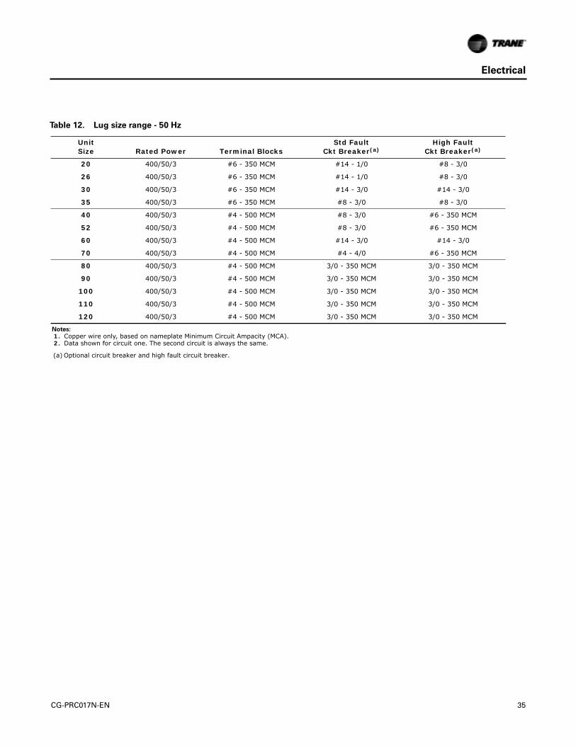
Electrical
Table 12. Lug size range - 50 Hz
Unit Size Rated Power Terminal Blocks
Std Fault Ckt Breaker(a)
High Fault Ckt Breaker(a)
20 400/50/3 #6 - 350 MCM #14 - 1/0 #8 - 3/0
26 400/50/3 #6 - 350 MCM #14 - 1/0 #8 - 3/0
30 400/50/3 #6 - 350 MCM #14 - 3/0 #14 - 3/0
35 400/50/3 #6 - 350 MCM #8 - 3/0 #8 - 3/0
40 400/50/3 #4 - 500 MCM #8 - 3/0 #6 - 350 MCM
52 400/50/3 #4 - 500 MCM #8 - 3/0 #6 - 350 MCM
60 400/50/3 #4 - 500 MCM #14 - 3/0 #14 - 3/0
70 400/50/3 #4 - 500 MCM #4 - 4/0 #6 - 350 MCM
80 400/50/3 #4 - 500 MCM 3/0 - 350 MCM 3/0 - 350 MCM
90 400/50/3 #4 - 500 MCM 3/0 - 350 MCM 3/0 - 350 MCM
100 400/50/3 #4 - 500 MCM 3/0 - 350 MCM 3/0 - 350 MCM
110 400/50/3 #4 - 500 MCM 3/0 - 350 MCM 3/0 - 350 MCM
120 400/50/3 #4 - 500 MCM 3/0 - 350 MCM 3/0 - 350 MCM
Notes:
1. Copper wire only, based on nameplate Minimum Circuit Ampacity (MCA). 2. Data shown for circuit one. The second circuit is always the same.
(a) Optional circuit breaker and high fault circuit breaker.
CG-PRC017N-EN 35
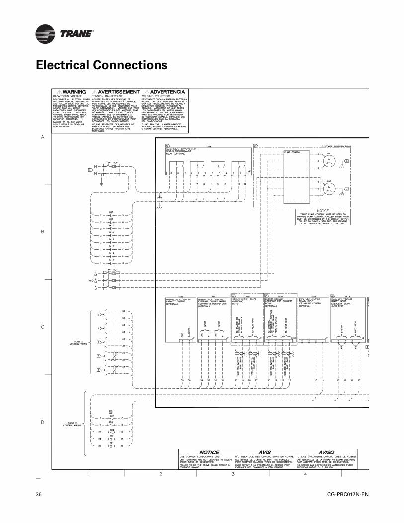
Electrical Connections
36 CG-PRC017N-EN

Electrical Connections
C
TRANE
CG-PRC017N-EN 37

Electrical Connections
38 CG-PRC017N-EN

Electrical Connections
C
TRANE
CG-PRC017N-EN 39
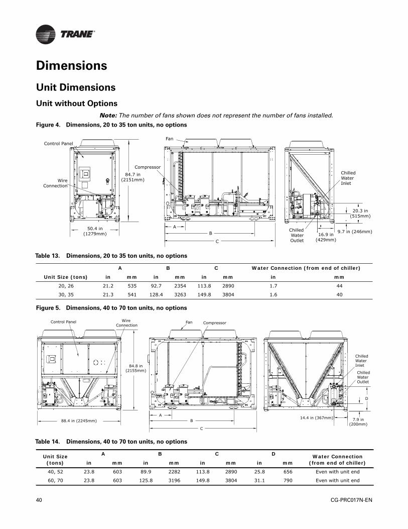
Dimensions
Unit Dimensions
Unit without Options
Note: The number of fans shown does not represent the number of fans installed.
Figure 4. Dimensions, 20 to 35 ton units, no options
Table 13. Dimensions, 20 to 35 ton units, no options
Unit Size (tons)
A B C Water Connection (from end of chiller)
in mm in mm in mm in mm
20, 26 21.2 535 92.7 2354 113.8 2890 1.7 44
30, 35 21.3 541 128.4 3263 149.8 3804 1.6 40
Figure 5. Dimensions, 40 to 70 ton units, no options
Table 14. Dimensions, 40 to 70 ton units, no options
Unit Size (tons)
A B C D Water Connection(from end of chiller)in mm in mm in mm in mm
40, 52 23.8 603 89.9 2282 113.8 2890 25.8 656 Even with unit end
60, 70 23.8 603 125.8 3196 149.8 3804 31.1 790 Even with unit end
84.7 in(2151mm)
Control Panel
WireConnection
50.4 in(1279mm)
ChilledWaterInlet
ChilledWaterOutlet
9.7 in (246mm)
20.3 in(515mm)
16.9 in(429mm)
Compressor
Fan
AB
C
Control Panel Wire Connection
84.8 in(2155mm)
88.4 in (2245mm)
Fan Compressor
AB
C
ChilledWaterInlet
ChilledWaterOutlet
14.4 in (367mm) 7.9 in(200mm)
D
40 CG-PRC017N-EN

Dimensions
Figure 6. Dimensions, 80 to 120 ton units, no options
Table 15. Dimensions, 80 to 120 ton units, no options
A B C Water Connection (from end of chiller)
Unit Size (tons) in mm in mm in mm in mm
80, 90 29.6 751 89.2 2265 143.1 3634 5.5 139
100, 110, 120 29.6 751 111.7 2837 165.9 4214 5.5 139
Control Panel
Wire Connection
88.2 in (2240mm)
92.5 in(2349mm)
Fan Compressor
AB
C
ChilledWaterInlet
ChilledWaterOutlet
7.9 in(200mm)
31.1 in(790 mm)
11.5 in (292mm)
Figure 7. Dimensions, 130 ton unit, no options
Control PanelWire Connection
88.2 in(2240mm)
92.5 in(2349mm)
FanCompressor
ChilledWaterInlet
ChilledWaterOutlet
149.8 in (3804mm)
201.9 in (5128mm)
31.1 in(790mm)
29.6 in (751mm)
11.5 in (292mm)7.9 in (199mm)
92.5 in(2349mm)
Water connections are 25 in (635mm) from unit end.
CG-PRC017N-EN 41
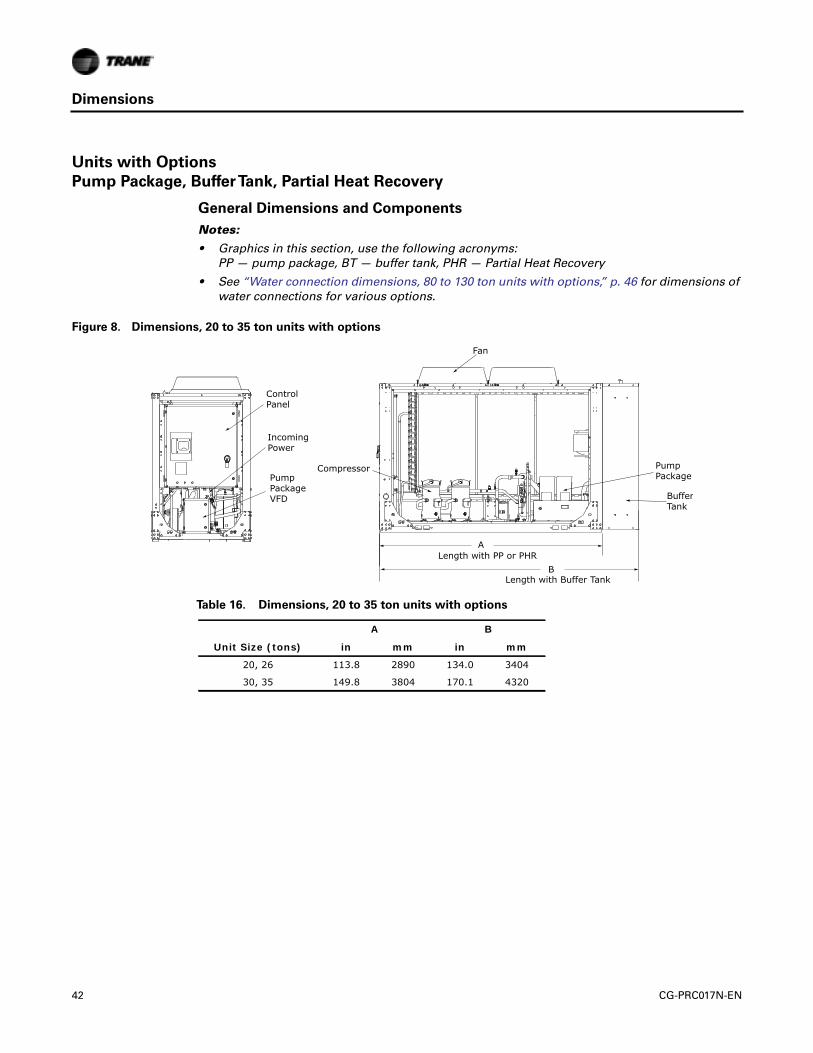
Dimensions
Units with Options
Pump Package, BufferTank, Partial Heat Recovery
General Dimensions and Components
Notes:
• Graphics in this section, use the following acronyms:PP — pump package, BT — buffer tank, PHR — Partial Heat Recovery
• See “Water connection dimensions, 80 to 130 ton units with options,” p. 46 for dimensions ofwater connections for various options.
Figure 8. Dimensions, 20 to 35 ton units with options
Fan
PumpPackage
BufferTank
Compressor
ControlPanel
IncomingPower
PumpPackageVFD
A
BLength with PP or PHR
Length with Buffer Tank
Table 16. Dimensions, 20 to 35 ton units with options
Unit Size (tons)
A B
in mm in mm
20, 26 113.8 2890 134.0 3404
30, 35 149.8 3804 170.1 4320
42 CG-PRC017N-EN

Dimensions
Note: For PHR units, add 2.2 in (56mm) to overall length.
Figure 9. Dimensions, 40 to 70 ton units with options
IncomingPower
Control Panel
PumpPackageVFD
Fan Compressor Pump PackageBufferTank
Length w/ PP or PHR
Length w/ Buffer Tank
A
B
Table 17. Dimensions, 40 to 70 ton units with options
Unit Size (tons)
A B
in mm in mm
40, 52 113.8 2890 134.2 3409
60, 70 149.8 3804 170.0 4318
Figure 10. Dimensions, 80 to 120 ton units with options
FanCompressor
BufferTank Pump Package
VFD
Pump Package
ControlPanel
IncomingPower
Length w/ PP or Buffer tankA
Table 18. Dimensions, 80 to 120 ton units with options
Unit Size (tons)
A
in mm
80, 90, 100 143.1 3634
110, 125 165.9 4214
CG-PRC017N-EN 43

Dimensions
Note: For PHR units, add 2.2 in (56mm) to overall length.
Figure 11. CGAM 130 ton, with options
Fan Compressor Buffer Tank Pump Package VFD
Pump Package
Length w/ PP or Buffer tank
201.9 in(5128mm)
ControlPanel
IncomingPower
44 CG-PRC017N-EN

Dimensions
Water Connections
Figure 12. Water connection dimensions, 20 to 35 ton units with options
ChilledWaterOutlet
ChilledWaterInlet
ChilledWaterInlet
ChilledWaterOutlet
HeatingInlet
HeatingOutlet23.9 in
(608mm)
16.2 in(411mm)
8.6 in(219mm)
B
15.2 in(385mm
7.2 in(182mm)
23.9 in(608mm)
10.4 in(266mm)
12.9 in(326mm)
A
PUMP PACKAGE BUFFER TANK PARTIAL HEAT RECOVERY
Water connections are recesssed1.3 in (33mm) from unit end.
Water connections arerecesssed from unit end.Inlet: 3.2 in (81mm)Outlet: 10.3 in (262mm)
Partial heat recovery connections are even with unit edge.The chilled water inlet and outlet connections are the sameas the standard unit unless pump package or buffer tank are ordered.
Table 19. Water connection dimensions, 20 to 35 ton units with options
Unit Size (tons)
A B
in mm in mm
20, 26 24.1 613 70.3 1784
30, 35 23.9 608 67.4 1712
Figure 13. Water connection dimensions, 40 to 70 ton units with options
ChilledWaterInlet
ChilledWaterOutlet
PUMP PACKAGE
9.2 in(234mm)
66.9 in (1696mm)
18.8 in(474mm)
19.7 in(499mm)
BUFFER TANK
ChilledWaterInlet
ChilledWaterOutlet
16.1 in(409mm)
19.6 in(498mm)
27.3 in(693mm)
24.3 in(617m)
Water connections are recessed1.3 in (33mm) from unit end.
Water connections are recessedfrom unit end:Inlet:3.2 in (81mm) Outlet: 8.5 in (216mm)
PARTIAL HEAT RECOVERYHeating Outlet Heating Inlet
54.8 in(1392mm)
45.3 in(1149mm)
44.2 in(1122mm)
Partial heat recovery connections are even with unit end.The chilled water connections are the same as the standardunit unless pump packageor buffer tank are ordered.
Table 20. Water connection dimensions, 40 to 70 ton units with options
Unit Size (tons)
A B C
in mm in mm in mm
40, 52 24.3 617 45.3 1149 54.8 1392
60, 70 24.2 615 45.6 1158 55.2 1401
CG-PRC017N-EN 45

Dimensions
Figure 14. Water connection dimensions, 80 to 130 ton units with options (a)
(a) See Table 21 for water connections distance from end/side of unit.
Table 21. Water connection dimensions, 80 to 130 ton units with options
Unit Size (tons)
Pump Package(a) Buffer Tank(a) Partial Heat Recovery(b)
Inlet Outlet Inlet Outlet Inlet Outlet
in mm in mm in mm in mm in mm in mm
80, 90T 5.9 151 5.9 151 6.2 158 6.2 158 1.1 28 1.1 28
100, 110, 120T 5.9 151 5.9 151 6 153 6 153 1.1 28 1.1 28
130T 6.3 159 25 635 5.9 150 27.7 703 1.1 28 1.1 28
(a) Distance from end of unit.(b) Distance from side of unit.
PARTIAL HEAT RECOVERY
HotWaterOutlet
HotWaterInlet
PUMP PACKAGE(with or without BUFFER TANK)
ChilledWaterInlet
Chilled WaterOutlet
28.9 in(733mm)
7.9 in(199mm)
11.5 in(292mm)22.6 in (575mm)
49.6 in(1260mm)
40.4 in(1026mm) 0.7 in
(18mm)
46 CG-PRC017N-EN

Dimensions
Service Clearances
Notes:
• Number of fans and panel doors shown does not represent the number of fans installed.
• More clearance may be needed for airflow, depending on installation.
Figure 15. CGAM service clearances
Table 22. CGAM service clearance dimensions
A B C D
Unit Size in mm in mm in mm in mm
20 to 35 ton 47.2 1200 31.5 800 23.6 600 39.4 1000
40 to 70 ton 47.2 1200 31.5 800 39.4 1000 39.4 1000
80 to 130 ton 47.2 1200 39.4 1000 39.4 1000 39.4 1000
D
BA
DoorSwing
C
CG-PRC017N-EN 47

Dimensions
Mounting Locations
Important: All mounting holes are 0.75 in (19mm) in diameter.
Unit without Wind Load Rating
Note: Mounting locations shown below are for units without wind load rating. For units with windload rating (model number digit 17=D), additional mounting points are required. See “Unitswith Wind Load Rating,” p. 51.
Figure 16. Mounting locations, 20 to 35 ton
Con
trol
Pan
el S
ide
Chi
lled
Wat
er C
onne
ctio
n Sid
e
1.5 in (38 mm)
(Distance from edge to middle of mounting hole)
47.2 in(1199 mm)
A
B
Total of four (4) mounting holes
Table 23. Mounting locations, 20 to 35 ton units without wind load option
Unit Size (tons)
A B
in mm in mm
20, 26 21.0 533 101.2 2570
30, 35 21.9 556 132.2 3358
48 CG-PRC017N-EN

Dimensions
Figure 17. Mounting locations, 40 and 52 ton
Con
trol
Pan
el S
ide
Chi
lled
Wat
er C
onne
ctio
n Sid
e
1.5 in (38 mm) (Distance from edge to middle of mounting hole)
85.4 in(2164 mm)
19.4 in(493mm)
94 in (2388 mm)
Total of four (4) mounting holes
Figure 18. Mounting locations, 60 and 70 ton
Con
trol
Pan
el S
ide
Chi
lled
Wat
er C
onne
ctio
n Sid
e
1.5 in (38 mm) (Distance from edge to middle of mounting hole)
85.2 in(2164 mm)
19.4 in(493mm)
79.7 in (2024 mm)
Total of six (6) mounting holes
129.8 in (3297 mm)
CG-PRC017N-EN 49

Dimensions
Figure 19. Mounting locations, 80 to 120 ton
Con
trol
Pan
el S
ide
Chi
lled
Wat
er C
onne
ctio
n Sid
e
1.5 in (38 mm) (Distance from edge to middle of mounting hole)
85.2 in(2164 mm)
30.2 in(767 mm)
A
Total of six (6) mounting holes
B
Table 24. Mounting locations, 80 to 120 ton units without wind load option
Unit Size (tons)
A B
in mm in mm
80, 90 83.7 2126 123.9 3147
100, 110, 120 89.2 2266 146.9 3731
Figure 20. Mounting locations, 130 ton
Con
trol
Pan
el S
ide
Chi
lled
Wat
er C
onne
ctio
n Sid
e
1.5 in (38 mm) (Distance from edge to middle of mounting hole)
85.2 in(2164 mm)
69.5 in (1765 mm)
Total of eight (8) mounting holes
130.6 in (3317 mm)
163 in (4140 mm)
30.2 in (767 mm)
50 CG-PRC017N-EN

Dimensions
Units with Wind Load Rating
For units with wind load rating (model number digit 17 = D), additional mounting points arerequired as shown below. All mounting points in previous section remain the same.
Figure 21. Additional mounting locations for 40 and 52 ton units with wind load option
Con
trol
Pan
el S
ide
Chi
lled
Wat
er C
onne
ctio
n Sid
eHole diameter 0.75 in (19mm)
1.5 in (38 mm)
(Distance from edge to middle of mounting hole)
85.4 in(2164 mm)
2.1 in(53.3 mm)
111.4 in (2829 mm)
Total of four (4) additional mounting holes for wind load option
CG-PRC017N-EN 51

Dimensions
Figure 22. Additional mounting locations for 60 and 70 ton units with wind load option
Con
trol
Pan
el S
ide
Chi
lled
Wat
er C
onne
ctio
n Sid
e
Hole diameter 0.75 in (19mm)
1.5 in (38 mm)
(Distance from edge to middle of mounting hole)
85.4 in(2164 mm)
147.4 in (3744 mm)
Total of two (2) additional mounting holes for wind load option
Figure 23. Additional mounting locations for 80 to 130 ton units with wind load option
Con
trol
Pan
el S
ide
Chi
lled
Wat
er C
onne
ctio
n Sid
e
Hole diameter 0.75 in (19mm)
1.5 in (38 mm)
(Distance from edge to middle of mounting hole)
85.9 in(2182 mm)
2.0 in(50.8 mm)
Total of two (2) additional mounting holes for wind load option
52 CG-PRC017N-EN

Weights
Base Units
RoundTube and Plate Fin Condenser Coils
Notes:
• Base unit weights include aluminum fins, refrigerant charge, elastomeric isolators, circuitbreakers and louvers.
• For units with microchannel condenser coils, see “Microchannel Condenser Coils,” p. 56.
• These weights do NOT include the following options: partial heat recovery, copper fins orseismic isolators. See “Option Weights,” p. 58 for additional weight added by these optionselections.
Table 25. Base unit weights, 60 Hz, round tube and plate fin condenser — I-P (lb)
Unit Size
(Tons)Base Unit
Base UnitWith Pump Package
Base UnitWith Pump Package and
Buffer Tank
Shipping Operating Shipping Operating Shipping Operating
High Efficiency
20 2185 2208 2726 2814 3252 4491
26 2249 2278 2790 2891 3317 4562
30 2846 2880 3388 3497 3915 5163
35 2878 2920 3420 3546 3947 5204
40 3666 3697 4285 4383 4876 6116
52 3761 3806 4379 4506 4971 6225
60 4978 5033 5814 5986 6406 7695
70 5045 5121 5881 6094 6473 7782
80 5607 5692 6486 6790 7077 8561
90 5859 5961 6738 7075 7329 8830
100 6646 6759 7549 7909 8265 10136
110 6724 6846 7627 8005 8343 10223
120 6762 6884 8018 8396 8733 10614
130 7753 7900 9006 9430 9722 11623
Extra Efficiency
20 2258 2281 2798 2887 3325 4564
26 2322 2351 2863 2964 3389 4634
30 2945 2979 3487 3596 4014 5262
35 3023 3065 3565 3691 4092 5349
40 3812 3843 4431 4529 5022 6262
52 3959 4004 4578 4705 5169 6423
60 5177 5232 6013 6184 6604 7893
70 5118 5194 5954 6166 6545 7855
110 6724 6846 7627 8005 8343 10223
120 6762 6884 8018 8396 8733 10614
Note: All weights ±3%.
CG-PRC017N-EN 53

Weights
Table 26. Base unit weights, 60 Hz, round tube and plate fin condenser — SI (kg)
Unit Size
(Tons)Base Unit
Base UnitWith Pump Package
Base UnitWith Pump Package and
Buffer Tank
Shipping Operating Shipping Operating Shipping Operating
High Efficiency
20 991 1002 1236 1277 1475 2037
26 1020 1034 1265 1311 1504 2069
30 1291 1306 1537 1586 1776 2342
35 1305 1325 1551 1608 1790 2360
40 1663 1677 1944 1988 2212 2774
52 1706 1726 1987 2044 2255 2824
60 2258 2283 2637 2715 2906 3490
70 2289 2323 2668 2764 2936 3530
80 2543 2582 2942 3080 3210 3883
90 2658 2704 3056 3209 3324 4005
100 3015 3066 3424 3587 3749 4598
110 3050 3105 3460 3631 3784 4637
120 3067 3122 3637 3808 3961 4814
130 3517 3583 4085 4277 4410 5272
Extra Efficiency
20 1024 1035 1269 1310 1508 2070
26 1053 1066 1298 1344 1537 2102
30 1336 1351 1582 1631 1821 2387
35 1371 1390 1617 1674 1856 2426
40 1729 1743 2010 2054 2278 2840
52 1796 1816 2077 2134 2345 2914
60 2348 2373 2727 2805 2996 3580
70 2322 2356 2701 2797 2969 3563
110 3050 3105 3460 3631 3784 4637
120 3067 3122 3637 3808 3961 4814
Note: All weights ±3%.
54 CG-PRC017N-EN

Weights
Table 27. Base unit weights, 50 Hz, round tube and plate fin condenser
Unit Size (Tons)
I-P Units (lb) SI Units (kg)
Shipping Operating Shipping Operating
High Efficiency
20 2187 2210 992 1002
26 2249 2278 1020 1034
30 2846 2880 1291 1306
35 2878 2920 1305 1325
40 3666 3697 1663 1677
52 3761 3806 1706 1726
60 4978 5033 2258 2283
70 5045 5121 2289 2323
80 5607 5692 2543 2582
90 5858 5960 2657 2703
100 6630 6743 3007 3059
110 6713 6835 3045 3100
120 6758 6880 3065 3121
Extra Efficiency
20 2260 2283 1025 1035
26 2322 2351 1053 1066
30 2945 2979 1336 1351
35 3023 3065 1371 1390
40 3812 3843 1729 1743
52 3959 4004 1796 1816
60 5177 5232 2348 2373
70 5118 5194 2322 2356
110 6713 6835 3045 3100
120 6758 6880 3065 3121
Note: All weights ±3%.
CG-PRC017N-EN 55

Weights
Microchannel Condenser Coils
Notes:
• Base unit weights include refrigerant charge, isolators, circuit breakers and louvers.
• For units with round tube and plate fin condensers, see “RoundTube and Plate Fin CondenserCoils,” p. 53.
Table 28. Base unit weights, 60 Hz, microchannel condenser — I-P (lb)
Unit Size
(Tons)
Base UnitBase Unit
With Pump PackageBase Unit
With Pump Package and Buffer Tank
Shipping Operating Shipping Operating Shipping Operating
High Efficiency
20 1967 1975 2507 2582 3034 4259
26 2030 2046 2571 2659 3098 4329
30 2388 2403 2929 3021 3456 4686
35 2608 2630 3150 3256 3677 4914
40 3307 3314 3926 3999 4517 5732
52 3402 3422 4021 4122 4612 5840
60 4136 4156 4972 5108 5563 6817
70 4579 4616 5415 5589 6006 7278
80 4888 4899 5766 5996 6357 7768
90 5141 5163 6020 6277 6611 8032
100 5816 5838 6719 6988 7434 9215
110 5893 5924 6796 7083 7511 9301
120 5930 5966 7186 7477 7902 9696
130 6722 6757 7976 8287 8691 10480
Note: All weights ±3%.
Table 29. Base unit weights, 60 Hz, microchannel condenser — SI (kg)
Unit Size
(Tons)
Base UnitBase Unit
With Pump PackageBase Unit
With Pump Package and Buffer Tank
Shipping Operating Shipping Operating Shipping Operating
High Efficiency
20 892 896 1137 1171 1376 1932
26 921 928 1166 1206 1405 1964
30 1083 1090 1329 1370 1568 2126
35 1183 1193 1429 1477 1668 2229
40 1500 1503 1781 1814 2049 2600
52 1543 1552 1824 1870 2092 2649
60 1876 1885 2255 2317 2523 3092
70 2077 2094 2456 2535 2724 3301
80 2217 2222 2616 2720 2884 3523
90 2332 2342 2731 2847 2999 3643
100 2638 2648 3048 3170 3372 4180
110 2673 2687 3083 3213 3407 4219
120 2690 2706 3260 3392 3584 4398
130 3049 3065 3618 3759 3942 4754
Note: All weights ±3%.
56 CG-PRC017N-EN

Weights
Table 30. Base unit weights, 50 Hz, microchannel condenser
Unit Size (Tons)
I-P (lb) SI (kg)
Shipping Operating Shipping Operating
High Efficiency
20 1967 1978 892 897
26 2030 2046 921 928
30 2388 2403 1083 1090
35 2608 2630 1183 1193
40 3307 3314 1500 1503
52 3402 3422 1543 1552
60 4136 4156 1876 1885
70 4579 4616 2077 2094
80 4888 4899 2217 2222
90 5139 5163 2331 2342
100 5798 5822 2630 2641
110 5882 5913 2668 2682
120 5926 5961 2688 2704
Note: All weights ±3%.
CG-PRC017N-EN 57

Weights
Option Weights
Note: Weights listed below are in addition to base unit weights found in previous section. For totalunit weight, add option weights to base unit weight found in “RoundTube and Plate FinCondenser Coils,” p. 53.
Table 31. Option weights, 60 Hz, round tube and plate fin condenser
Unit Size
(tons)
I-P Units (lb) SI Units (kg)
Partial Heat Recovery Copper Fins
Seismic Isolator
Partial Heat Recovery Copper Fins
Seismic Isolator Shipping Operating Shipping Operating
High Efficiency
20 39 63 258 160 18 28 117 73
26 39 70 258 160 18 32 117 73
30 47 82 359 160 21 37 163 73
35 47 91 359 160 21 41 163 73
40 94 128 516 160 43 58 234 73
52 94 143 516 160 43 65 234 73
60 111 170 719 240 50 77 326 109
70 111 191 719 240 50 87 326 109
80 170 260 1270 240 77 118 576 109
90 170 279 1270 240 77 126 576 109
100 178 298 1512 240 81 135 686 109
110 178 307 1512 240 81 139 686 109
120 178 310 1512 240 81 140 686 109
130 178 335 1889 320 81 152 857 145
Extra Efficiency
20 39 63 258 - 18 28 117 -
26 39 70 258 - 18 32 117 -
30 47 82 360 - 21 37 163 -
35 47 91 360 - 21 41 163 -
40 94 128 516 - 43 58 234 -
52 94 143 516 - 43 65 234 -
60 111 170 720 - 50 77 326 -
70 111 191 720 - 50 87 326 -
110 178 307 1512 - 81 139 686 -
120 178 310 1512 - 81 140 686 -
Note: All weights ±3%.
58 CG-PRC017N-EN

Weights
Table 32. Option weights, 50 Hz, round tube and plate fin condenser
Unit Size
(tons)
I-P Units (lb) SI Units (kg)
Partial Heat Recovery Copper
FinsSeismic Isolator
Partial Heat Recovery Copper
FinsSeismic Isolator Shipping Operating Shipping Operating
High Efficiency
20 40 24 258 160 18 11 117 73
26 40 31 258 160 18 14 117 73
30 46 35 359 160 21 16 163 73
35 46 44 359 160 21 20 163 73
40 95 33 516 160 43 15 234 73
52 95 49 516 160 43 20 234 73
60 110 60 719 240 50 27 326 109
70 110 79 719 240 50 36 326 109
80 170 90 1270 240 77 41 576 109
90 170 108 1270 240 77 49 576 109
100 179 119 1512 240 81 54 686 109
110 179 130 1512 240 81 59 686 109
120 179 130 1512 240 81 59 686 109
Extra Efficiency
20 40 24 258 - 18 11 117 -
26 40 31 258 - 18 14 117 -
30 46 35 359 - 21 16 163 -
35 46 44 359 - 21 20 163 -
40 95 33 516 - 43 15 234 -
52 95 49 516 - 43 22 234 -
60 110 60 719 - 50 27 326 -
70 110 79 719 - 50 36 326 -
110 179 130 1512 - 81 59 686 -
120 179 130 1512 - 81 59 686 -
Note: All weights ±3%.
CG-PRC017N-EN 59

Mechanical Specifications
General
Units are constructed of galvanized steel frame with galvanized steel panels and access doors.Component surfaces are finished with a powder-coated paint. Each unit ships with full operatingcharges of refrigerant and oil.
Certified AHRI Performance
Trane air-cooled chillers are rated within the scope of theAir-Conditioning, Heating & RefrigerationInstitute (AHRI) Certification Program and display theAHRI Certified® mark as a visual confirmationof conformance to the certification sections of AHRI Standard 550/590 (I-P) and ANSI/AHRIStandard 551/591 (SI).The applications in this catalog specifically excluded from the AHRIcertification program are:
• Custom Units
• Units produced outside of the USA for installations outside the USA
• Evaporatively-cooled chillers
• Units with evaporators that use fluid other than fresh water except units containing freezeprotection fluids in the condenser or in the evaporator with a leaving chilled fluid temperatureabove 32°F [0°C] are certified when rated per the Standard with water.
Compressor and Motor
The unit is equipped with two or more hermetic, direct-drive, 3600 rpm 60 Hz (3000 rpm 50 Hz)suction gas-cooled scroll compressors.The simple design has only three major moving parts anda completely enclosed compression chamber which leads to increased efficiency. Overloadprotection is included.The compressor includes: centrifugal oil pump, oil level sight glass and oilcharging valve. Each compressor will have compressor heaters installed and properly sized tominimize the amount of liquid refrigerant present in the oil sump during off cycles.
Unit-Mounted Starter
The control panel is designed per UL 1995.The starter is an across-the-line configuration, factory-mounted and fully pre-wired to the compressor motor and control panel. A factory-installed,factory-wired 820 VA control power transformer provides all unit control power (120 Vacsecondary) andTrane CH530 module power (24 Vac secondary). Power line connection type isstandard with a terminal block.
Evaporator
Braze plate heat exchanger is made of stainless steel with copper as the braze material. It isdesigned to withstand a refrigerant side working pressure of 430 psig (29.6 bars) and a watersideworking pressure of 150 psig (10.5 bars). Evaporator is tested at 1.1 times maximum allowablerefrigerant side working pressure and 1.5 times maximum allowable water side working pressure.It has one water pass. Immersion heaters protect the evaporator to an ambient of -20°F (-29°C).
The evaporator is covered with factory-installed 0.75 inch (19.05 mm) Armaflex II or equal (k=0.28)insulation. Foam insulation is used on the suction line. Water pipe extensions with insulation gofrom the evaporator to the edge of the unit.
Condenser
Air-cooled microchannel condenser coils use all aluminum brazed fin construction. Each slab issplit horizontally into separate condensing and subcooling coils that are connected by either a
60 CG-PRC017N-EN

Mechanical Specifications
copper tube or receiver tank.The maximum allowable working pressure of the condenser is 650psig (44.8 bars). Condensers are factory proof and leak tested at 715 psig (49.3 bars). Coils can becleaned with high pressure water.
Optional round tube and plate fin air-cooled condenser coils have aluminum fins mechanicallybonded to internally-finned copper tubing.The condenser coil has an integral subcooling circuit.The maximum allowable working pressure of the condenser is 650 psig (44.8 bars). Condensers arefactory proof and leak tested at 715 psig (49.3 bars).
Direct-drive vertical discharge condenser fans are balanced.Three-phase condenser fan motorswith permanently lubricated ball bearings and external thermal overload protection are provided.
Units start and operate from 0°F to 125°F (-18°C to 52°C) for wide ambient. Wide ambient allowsoperation down to 0°F which is accomplished by a variable speed fan on each circuit that modulatesto maintain system differential pressure.
Refrigerant Circuit and Capacity Modulation
The 20-35 ton units have single refrigerant circuits.The 40-130 ton units have dual refrigerantcircuits. Each refrigerant circuit hasTrane scroll compressors piped in parallel with a passive oilmanagement system. A passive oil management system maintains proper oil levels withincompressors and has no moving parts. Each refrigerant circuit includes filter drier, electronicexpansion valve, and liquid line and discharge service valves.
Capacity modulation is achieved by turning compressors on and off. The 20-35 ton units have twocapacity stages. The 40-120 ton units have four capacity stages.The 130 ton unit has six capacitystages.
Unit Controls (Trane CH530)
The microprocessor-based control panel is factory-installed and factory-tested.The control systemis powered by a pre-wired control power transformer, and will turn on and off compressors to meetthe load. Microprocessor-based chilled water reset based on return water is standard.
TheTrane CH530 microprocessor automatically acts to prevent unit shutdown due to abnormaloperating conditions associated with low evaporator refrigerant temperature and high condensingtemperature. If an abnormal operating condition continues and the protective limit is reached, themachine will shut down.
The panel includes machine protection for the following conditions:
• Low evaporator refrigerant temperature and pressure
• High condenser refrigerant pressure
• Critical sensor or detection circuit faults
• High compressor discharge temperature (with low temp evaporator)
• Lost communication between modules
• Electrical distribution faults: phase loss, phase reversal or over temperature protection
• External and local emergency stop
• Loss of evaporator water flow
When a fault is detected, the control system conducts more than 100 diagnostic checks and displaysresults.The display will identify the fault, indicate date, time, and operating mode at time ofoccurrence, and provide type of reset required and a help message.
CG-PRC017N-EN 61

Mechanical Specifications
Clear Language Display Panel
Factory-mounted to the control panel door, the operator interface has an LCD touch-screen displayfor operator input and information output.This interface provides access to the followinginformation: evaporator report, condenser report, compressor report, ASHRAE Guideline 3 report,operator settings, service settings, service tests, and diagnostics.All diagnostics and messages aredisplayed in “clear language.”
Data contained in available reports includes:
• Water and air temperatures
• Refrigerant pressures and temperatures
• Flow switch status
• EXV position
• Compressor starts and run-time
All necessary settings and setpoints are programmed into the microprocessor-based controller viathe operator interface.The controller is capable of receiving signals simultaneously from a varietyof control sources, in any combination, and priority order of control sources can be programmed.The control source with priority determines active setpoints via the signal it sends to the controlpanel. Control sources may be:
• Local operator interface (standard)
• Hard-wired 4-20 mA or 2-10 Vdc signal from an external source (interface optional; controlsource not supplied)
• Time of day scheduling (optional capability available from local operator interface)
• LonTalk® LCI-C (interface optional; control source not supplied)
• BACNet® (interface optional; control source not supplied)
• TraneTracer® Summit system (interface optional; control source not supplied)
Quality Assurance
The quality management system applied byTrane has been subject to independent third-partyassessment and approval to ISO 9001-2008.The products described in this catalog are designed,manufactured and tested in accordance with the approved system requirements described in theTrane Quality Manual.
Options
Application Options
Ice-Making with Hardwired Interface
Unit controls are factory set to handle ice-making for thermal storage application. An additionaltemperature sensor, at the compressor discharge, enables full load operation of the chiller withentering evaporator fluid temperature between 20°F (-7°C) and 65°F (18°C) with glycol.
High Ambient
The unit starts and operates from 32°F to 125°F (0°C to 52°C).
Low-Temperature Processing
An additional temperature sensor, at the compressor discharge, enables leaving evaporator fluidtemperature between 10°F (-12.2°C) and 42°F (5.5°C) with glycol.
Leaving evaporator fluid temperatures below 10°F (-12.2°C) are also possible for specificapplications.
62 CG-PRC017N-EN

Mechanical Specifications
Partial Heat Recovery with Fan Control
A supplemental brazed plate heat exchanger is mounted in series to the condenser coil. Connectingpiping and inlet and outlet water sensors are included. CH530 controls display heat recovery inletand outlet water temperatures and controls the fans.The heat rejection to the partial heat recoveryheat exchanger is not controlled. Flow and temperature variations through the partial heat recoveryheat exchanger will vary.The partial heat recovery heat exchanger is typically used to preheat waterbefore it enters a boiler or other water heating process.
Dual High Head Pump Package
Pump package includes: two high head pumps,VFD, expansion vessels, drainage valves, shut-offvalves at entering and leaving connections.
The pump package is single point power integrated into the chiller unit power with a separatefactory wired control panel.The control of the pump is integrated into the chiller controller.TheCH530 displays evaporator pump starts and run-times. Freeze protection down to an ambient of-20°F (-29°C) is included as standard.The cold parts of the pump package will also be insulated.
Designed with one redundant pump, the chiller controls both pumps through a lead/lag and failure/recovery functionality.
A variable speed drive is installed in an additional panel to control the pump.The inverter isadjusted upon start up to balance the system flow and head requirements.The purpose is to saveon wasted pump energy caused by a traditional balancing valve.
BufferTank (only available with pump package)
The water tank is factory-installed for easy installation at the building site.The tank is engineeredfor continuous flow and is fully insulated as standard and is designed with freeze protection downto -20°F (-29°C).The purpose of the tank is to increase the chilled water circuit inertia, which isnecessary with short water loops. A high circuit inertia reduces the compressor’s cycling toincrease the compressor life span and allow for more precise water temperature accuracy. It alsosaves energy as compared to hot gas bypass.
Electrical Options
Circuit Breaker
A molded case standard interrupting capacity circuit breaker, factory pre-wired with terminal blockpower connections and equipped with a lockable external operator handle, is available todisconnect the chiller from main power.
Circuit Breaker with High Fault Rated Control Panel
A molded case high interrupting capacity circuit breaker, factory pre-wired with terminal blockpower connections and equipped with a lockable external operator handle, is available todisconnect the chiller from main power.
Short Circuit Rating
Short circuit rating of 5 kA or up to 65 kA is available.
Control Options
BACNet Interface
Allows user to easily interface with BACNet® via a single twisted-pair wiring to a factory-installedand tested communication board.
LonTalk/Tracer Summit Interface
LonTalk® (LCI-C) orTracer® Summit communications capabilities are available withcommunication link via single twisted-pair wiring to factory-installed and tested communicationboard.This option will support the functionality required to obtain LONMARK® certification.
CG-PRC017N-EN 63

Mechanical Specifications
Time of Day Scheduling
Time of day scheduling capabilities are available for scheduling single chiller applications throughTrane CH530 panel (without the need for building automation system - BAS).This feature allowsthe user to set up to ten events in a seven day time period.
External Chilled Water and Demand Limit Setpoint
Controls, sensors, and safeties allow reset of chilled water temperature, based on temperaturesignal, during periods of low outdoor air temperature (chilled water reset based on return chilledwater temperature is standard).The demand limit setpoint is communicated to a factory-installedand tested communication board through a 2-10 Vdc or 4-20 mA signal.
Percent Capacity
Output the number of compressors that are operating as an analog 2-10 Vdc or 4-20 mA signal.
Programmable Relays
Predefined, factory-installed, programmable relays allow the operation to select four relay outputs.Available outputs are: Alarm-Latching, Alarm-Auto Reset, General Alarm, Warning, Chiller LimitMode, Compressor Running, andTracer Control.
Other Options
Architectural Louvered Panels
Louvered panels cover the complete condensing coil and service area beneath the condenser.
Half Louvers
Louvered panels cover the condenser coil only. Available on the 80-130 ton units only.
Comprehensive Acoustic Package
This option includes acoustical treatment for compressor.
Condenser Coil - CompleteCoat
Condenser coils are made of aluminum fins (plate fins) mechanically bonded to internally finnedcopper tubes.The condenser box is then submerged in an epoxy polymer bath where anelectrostatic charge is used to uniformly deposit the epoxy onto the coil.This option resists bi-metallic corrosion and allows for operation in coastal environments.
Condenser Coil - Copper
Condenser coils are made of non-slit copper fins (plate fins) mechanically bonded to internallyfinned copper tubes. Copper fins and copper tubes reduce material deterioration due to galvaniccorrosion.
Condenser Coil - Microchannel
Microchannel condensing coils are all-aluminum coils with fully-brazed construction.This designreduces risk of leaks and provides increased coil rigidity — making them more rugged on thejobsite.
Microchannel all-aluminum construction provides several additional benefits:
• Light weight (simplifies coil handling)
• Easy to recycle
• Minimize galvanic corrosion
Their flat streamlined tubes with small ports and metallurgical tube-to-fin bond allow forexceptional heat transfer.
Bottom line, less refrigerant is being used, which creates a healthier and greener environment.
64 CG-PRC017N-EN

Mechanical Specifications
Isolators
Molded elastomeric isolators sized to reduce vibration transmission to the supporting structurewhen the unit is installed. Isolators ship with the chiller.
Isolators - Seismically Rated
Spring isolators are designed and tested to control the motion of the chiller during a seismic event.
Insulation for High Humidity
The evaporator is covered with factory-installed 1.25 inch (31.8 mm) Armaflex II or equal (k=0.28)insulation. Foam insulation is used on the suction line.
Nitrogen Charge
Unit is shipped with oil and a nitrogen charge in lieu of refrigerant.
PerformanceTest
Performance tests are available to certify chiller performance before shipment.
Rapid RestartTest
After completion of a standard full load witness test, power to the chiller will be cut and thenreapplied to demonstrate the chiller’s rapid restart capabilities for disaster relief.
Seismically Rated Unit — IBC
Unit is built and certified for seismic applications in accordance with the following InternationalBuilding Code (IBC) releases 2000, 2003, 2006 and 2009.
Seismically Rated Unit — OSHPD
Unit is built and certified for seismic applications in accordance with California Office of StatewideHealth Planning and Development (OSHPD).
Wind Load for Florida Hurricane
Unit is built and certified to meet the requirements of the 2014 Florida Building Code andASCE 7-10 for 186 mph wind speed, Exposure ‘C’, Risk Category III. Available for non-rooftopmounted units only.
CG-PRC017N-EN 65


Ingersoll Rand has a policy of continuous product and product data improvement and reserves the right to change design and specificationswithout notice.We are committed to using environmentally conscious print practices.
Ingersoll Rand (NYSE:IR) advances the quality of life by creating comfortable, sustainable and efficientenvironments. Our people and our family of brands—including Club Car®, Ingersoll Rand®, Thermo King® andTrane®—work together to enhance the quality and comfort of air in homes and buildings; transport and protectfood and perishables; and increase industrial productivity and efficiency. We are a global business committed to aworld of sustainable progress and enduring results.
The AHRI Certified mark indicates Ingersoll Rand’s participation in the AHRI Certification program. For verification of individual certified products,go to www.ahridirectory.org.
ingersollrand.com
©2017 Ingersoll RandCG-PRC017N-EN 06 Jul 2017Supersedes CG-PRC017M-EN (21 Feb 2017)