product catalogue - vrctech.com brochure.pdf · product catalogue. 2 2 calcpad ... design...
TRANSCRIPT

PROKON provides engineers with tools to streamline their
workfl ow in the structural and geotechnical spheres. The tools
are modular, but all are launched from the Prokon Calcpad, a very
powerful object for interaction with the design modules. Export
to PDF and a compact fi le format has made the Prokon Calcpad a
winning tool for designers. All the modules boast an extensive
help system, example fi les, support logging tools, and support
by qualifi ed engineers.
PRODUCT CATALOGUE

2
2
Calcpad
This is the main module from where you launch the
various analysis and design modules. You can also use
Calcpad to build calcsheets with design notes, drawings
and equations. The user may customise the calcsheet
layout to suit his/her style, using lines, text, labels, graphic
fi les and adding header items. The Prokon Calcpad
becomes the project database, containing all the output
tables and graphs of the various modules, as well as
imbedded input fi les.
Live Update
The Live Update utility provides a platform for comparing
and updating your Prokon installation. New versions can
quickly be downloaded and will automatically be installed.
3
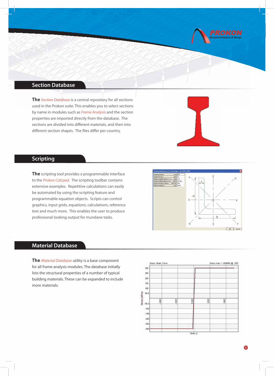
The Material Database utility is a base component
for all frame analysis modules. The database initially
lists the structural properties of a number of typical
building materials. These can be expanded to include
more materials.
Scripting
The scripting tool provides a programmable interface
to the Prokon Calcpad. The scripting toolbar contains
extensive examples. Repetitive calculations can easily
be automated by using the scripting feature and
programmable equation objects. Scripts can control
graphics, input grids, equations, calculations, reference
text and much more. This enables the user to produce
professional looking output for mundane tasks.
The Section Database is a central repository for all sections
used in the Prokon suite. This enables you to select sections
by name in modules such as Frame Analysis and the section
properties are imported directly from the database. The
sections are divided into diff erent materials, and then into
diff erent section shapes. The fi les diff er per country.
Section Database
Material Database
3

4
4
STRUCTURAL DESIGN MODULES
Frame Analysis
These can be divided into eight separate groups according to the structural material used,
design method employed, or the specifi c application of the module.
STRUCTURAL ANALYSIS MODULES
The Frame Analysis module supports the linear analysis of
a two dimensional frame consisting of beam elements. This
includes moment frames, trusses and/or grillage analyses.
Temperature eff ects and prescribed displacements may
also be added.
Displacements, beam end forces, moment envelopes,
reactions at service and ultimate loads are given. The
Frame module may be extended in several ways:
+3D extension: Three dimensional analyses may be
done, giving every node six degrees of freedom.
+Finite Element: Adds shell, brick and catenary cable
elements to the choice of input.
+Second Order & Buckling: This allows the used to
do a second order analysis on a frame, which allows
certain savings in the steel design modules to be
applied, or a buckling analysis, often used to point
out structurally unstable frames.
+Non-linear extension: Allows the user to analyse
both geometric and material non-linear behaviour.
+Dynamic Analysis extension: Calculation of mode
shapes and natural frequencies as well as seismic
and harmonic analyses are possible.
Concrete design calculations can be done on the
shell element output.
Frame analysis also links to design modules after an analysis
has been done. In this way all load cases/combinations
with the necessary forces are transferred to the applicable
module. Output may be viewed and included in your
calculations, in graphic format or in analysis reports.
Frame analysis also links to other software by way of
.DXF, .DWG fi les, CIS 2 and .SNF fi les for steel detailing
packages and by direct link to Autodesk Revit Structure.
■
■
■
■
■
■

5
This module allows the user to enter any shape which
will be meshed automatically and analysed using the
method specifi ed.
Plane Stress/Plane Strain Analysis
This module is a basic analysis tool for beams – any end
condition can be specifi ed. Point loads, point moments and
distributed loads may be entered for a complete evaluation
of the member forces and reactions. The user may select
beam sections from the Section Database or enter custom
section properties.
Single span beam analysis
The user may enter multiple elastic supports, with or
without gaps and any number of fi xed supports. Diagrams
of soil pressure, moment, shear and defl ections are given
as output.
Beam on elastic support analysis
5

Member Design for Combined Stresses
This module is used for checking and optimising steel
members subjected to a combination of axial force and
uniaxial or biaxial bending moments, e.g. beams and
columns in frames.
As with the Axial Stress design module, interactive
input may be entered by the user, alternatively it also
accepts input from the Frame Analysis and Single Span
Beam Analysis modules. All design parameters are editable
eg. maximum slenderness ratios per load case, eff ective
lengths, etc. In addition to this, internal nodes can be
defi ned and the accompanying eff ective lengths of each
member for every axis may be adjusted. Individual output
with all the necessary design equations may be added to
the output fi le for each element analysed.
6
STEEL MEMBER DESIGN MODULES
This module is used for checking and optimising steel
members subjected to axial stress only, e.g. truss members.
The input may be read from Frame Analysis output fi les or
input may be entered on the interactive input page. All
design parameters are editable e.g. maximum slenderness
ratios per load case, eff ective length factors, etc. The design
may be done to select the lightest possible sections, or to
evaluate the currently selected sections.
Member Design for Axial Stress

Crane Gantry Girder Design
This module supports several classes of cranes, multiple steel sections, capping sections,
multiple cranes on a single beam and more. It will quickly and accurately determine envelopes
for all the required design forces, moments and defl ections.
z
Plate Girder Design
This module supports almost any shape girder: stepped, straight or tapered girders may be
entered with varying end conditions. Lateral restraints are indicated along the length of the
beam. A full design report with calculations is generated, graphically indicating stiff eners,
design forces, moments and defl ections.
Plastic Frame Analysis and Design
This module does a linear or elasto-plastic analysis of a
frame. The input is similar to that of the Frame Analysis
program. All plastic hinges are shown graphically in the
output. In all other respects the output is identical to that
of Frame Analysis.
The use of plastic design methods is normally limited
to the design of continuous beams and single storey
frames with rigid joints, e.g. portal frames. It may also be
acceptable to use plastic methods for designing some
braced multi-storey planar frames.
7

Beam to Column Connection Design, Apex Connection Design
All I and H sections (universal columns and universal
beams) are supported. This is a moment connection design
module and bolted or welded connections may be defi ned.
The beam may be haunched and placed at any angle.
There is an optimisation function which provides the user
with a powerful tool to determine the best possible layout,
eg. web plates, stiff eners, bolt sizes and spacing, etc. The
design is immediately evaluated when any design change
if made, and all design checks are marked as a success
or failure. Full design calculations are given for all codes
of practice. A manufacturing detail is provided after the
design has been completed. Input may be transferred from
Frame Analysis output through a design link.
Hollow Section Connection Design
The Hollow Section Connection Design module does a
complete design of welded structural hollow section
connections. The connecting members may transmit axial
force and can be circular, square or rectangular hollow
sections. I-sections and H-sections (Universal Beams and
Universal Columns) can also be used for the main chord.
Various connection layouts can be designed. These
include K, T, N, X, and Y joints and combinations thereof.
8
STEEL CONNECTION DESIGN MODULES
Base Plate Design
Base plates for all hollow sections and I or H sections
may be designed. This module supports design for studs
or bolts, stiff ened or unstiff ened plates, and produces
graphic output of the bending moment in the plate, tensile
forces in the bolts and the distribution of the compressive
stress under the plate in the concrete substrate (for
bolted option). It also produces a detailed drawing for
manufacturing of the connection.

Double Angle Cleat Design, Fin Plate Design, End Plate Design
Bolt Group Design
This module evaluates eccentric forces on bolt groups,
in bearing or friction grip connections, with the option for
linear (Polar Moment) or non-linear (Instantaneous Centre
of Gyration) analysis. All bolt forces are shown graphically
and a minimum bolt size is determined.
Weld Group Design
This module evaluates eccentric forces on weld groups,
comprising fi llet welds with the option for linear (Polar
Moment) or non-linear (Instantaneous Centre of Gyration)
analysis. The resistance of the weld is adapted for the force
angle and the weld resistance is displayed graphically. An
input wizard allows the user to place welds according to
the most popular steel section outlines. A minimum weld
size is determined.
These are simple connection design modules (no
moment transfer). Sections may be chosen from the
Section Database, and the connection elements may be
optimised, as are the bolts and welds. Full calculations are
shown with graphic output. 3D views, sections, elevations
and plan views are shown with or without bolts and may be
exported to CAD software as details.
9

Continuous Beam & Slab Design
The Continuous Beam and Slab Design module is used to design and detail reinforced
concrete beams and slabs as encountered in typical building projects. The design incorporates
automated pattern loading and moment redistribution.
Cross-sections can include a mixture of rectangular, I, T and L-sections. Spans can have
constant or tapered sections. Entered dead and live loads are automatically applied as pattern
loads during the analysis. At ultimate limit state, moments and shears are redistributed to a
user specifi ed percentage. Both short-term and long-term defl ections are calculated.
Complete bending schedules can be generated for editing and printing using Padds. The
reinforcement details may be graphically edited by the designer, and is presented in user
friendly pages depicting entered, required and minimum reinforcement (as specifi ed by the
applicable code of practice).
Frame Analysis output may be used to generate input for this module.
CAPTAIN : Prestressed Beam/Slab Design
CAPTAIN addresses all aspects of a post-tensioned system. Using graphic representations
of all input, the designer can monitor and change all factors of the design at any time with
immediate graphically understandable feedback. Functionality includes (but is in no way
limited to) slab sections or user (eg bridge deck) sections, parabolic or harped tendons,
automatic placement of tendons to balance specifi ed loads, placement of additional rebar,
punching shear design, profi le scheduling, etc.
10
CONCRETE DESIGN

Finite Element Slab Design
Similar to the Frame Analysis module when using plate
elements, input is generated to represent a slab. Input fi les
for this module may also be generated with Padds. Point
loads, and distributed loads may be added in load cases
and then combined. Output is graphic and shows colour
coded bands depicting contours of reinforcement values.
Displacement, reactions, moments and reinforcement
required (by means of Wood & Armer conversion) are
also given.
Rectangular Slab Panel Design
As indicated by the name, this module is used to design
slabs by panel. The input requires the user to enter end
conditions for every edge of the panel. The edge may
be restrained for displacement (Support) and/or rotation
(continuous). Point loads, line loads and UDL’s maybe
added in load cases with diff erent load factors. Graphic
contour output is given for moment, defl ections and
reinforcement. In addition to this an automatic detailing
page will display a possible bending schedule and detailing
layout. The user may change any of the reinforcement
values on this schedule.
Rectangular Column Design
This is a design module for quick evaluation of a
rectangular section. The required reinforcement is given,
as well as a bending schedule in Padds format. The user
is required to enter bracing and fi xity parameters for
both principal axes, and the column dimensions. Loads,
including top and bottom moments about both axes, may
be entered in load cases. The column is designed according
to the specifi ed code of practice and the interaction
diagrams for both axes are plotted. The user can control
the end conditions, stirrup layout and many more options
when creating the bending schedule. Frame Analysis
output may be used to generate input for this module.
11

Circular Column Design
This is a design module for quick evaluation of a circular
section. The required reinforcement is given, as well as a
bending schedule in Padds format. The user is required to
enter bracing and fi xity parameters for both principal axes,
and the column dimensions. Loads, including top and
bottom moments about both axes, may be entered in load
cases. The column is designed according to the specifi ed
code of practice and the interaction diagram is plotted.
The user can control the end conditions, stirrup layout and
many more options when creating the bending schedule.
Frame Analysis output may be used to generate input for
this module.
General Column Design
This is a design evaluation module for any general
column section. No quick designs or reinforcement
layouts are done. The user is required to enter bracing
and fi xity parameters for both principal axes, and the
column dimensions. This may include any outline shape
with or without voids in the column body. The user
should also enter the positions and sizes of longitudinal
reinforcement. Loads, including top and bottom moments
about both axes, may be entered in load cases. The column
is designed according to the specifi ed code of practice
and the interaction diagrams for both axes are plotted.
Frame Analysis output may be used to generate input for
this module, or Padds may be used to create the section of
the column.
12

Concrete Retaining Wall Design
The Retaining Wall Design module is used to analyse
retaining walls for soil and surcharge loads or seismic
load conditions. Various types of walls can be considered,
including cantilever, simply supported and propped
cantilever walls. Complex wall geometry may be entered
with many options for the design methodology. Rankine
and Coulomb theory are supported and seepage may
be allowed for if needed. Certain dimensions of the
wall may be optimised. A full design is performed with
safety factors for slip and overturning given at ULS and
SLS. The moments in the walls are used to determine
required reinforcement values. Al these values are shown
graphically and an editable bending schedule is provided
for a length of wall.
Concrete Base Design
Bases with columns, stub columns, or no concrete column
may be designed. A maximum of two columns may be
placed on the base, and diagrams of the stress distribution,
with applicable safety factors and moments are provided
during the design. A check for punching shear is also done.
Finally a bending schedule with an exhaustive amount of
options is provided. Input for this module may be derived
from frame analysis via a design link.
Crack Width Design
A section is analysed for crack width due to moment,
direct tension and temperature loads. Several options
for reinforcement size and spacing are provided with
the accompanying crack widths, according to the
design parameters.
13

Concrete Section Design
The Concrete Section Design module is a simple utility for
designing concrete sections for combined bending, shear
and torsion. In addition to the forces normally accounted
for in a continuous beam design, this module also accounts
for, and reinforces for torsion moments. Full tabular design
tables are provided.
Punching Shear Design
This module is designed for punching shear checks on
reinforced slabs (for punching on post-tensioned slabs
use Captain). The slab extremities relative to the column
position need to be defi ned to determine whether they
aff ect the perimeters. Longitudinal reinforcement in the
two main directions may be specifi ed as an area or bars at
a certain spacing. Critical load cases with corresponding
amounts of punching shear reinforcement are given as
design values.
Timber Member Design
The Timber Member Design module is used to check and
optimise timber members subjected to a combination of
axial and biaxial bending stresses, e.g. beams, frames and
trusses. The program primarily acts as a post-processor for
the Frame Analysis module. It also has an interactive mode
for the quick design or checking of individual members
without needing to perform a frame analysis.
Timber and glued laminated timber load bearing
members are supported.
14
TIMBER DESIGN

Masonry Section Design
Masonry Section Design is used for the design of masonry
spanning openings. The module supports masonry units
of arbitrary dimension and various nominal strengths.
Characteristic masonry unit strengths can be specifi ed or
calculated based on the chosen code of practice. Single
leaf, collar-jointed and grouted cavity arrangements are
available. The output includes a design summary and
sketch as well as a detailed report.
Masonry Wall Design
Masonry Wall Design supports the design of bearing walls
(axially loaded) and wall panels (loaded normal to the plane
of the wall). Similar to Masonry Section Design, masonry
units of any dimension and strength can be used and
the same arrangements are supported. The output also
includes a design summary and detailed report.
15
MASONRY DESIGN

PADDS
Padds is a CAD program designed specifi cally for the
structural engineer. Al the basic CAD procedures are
available to create or edit drawings. Elements like lines,
arcs, circles, splines, text, hatch, dimensions, blocks, and
construction lines are all supported with numerous creation
and editing functions. In addition to this, Padds also links
with the Section Database to enable users to draw sections,
elevations and plans of all sections in the database. This
greatly accelerates steel detailing It also contains a large
number of reinforcement detailing functions and even
contains functions for detailing complete staircases.
A full library of commonly used structural and
architectural entities is available and the user can expand
this repository at any time. Included in this is also a function
to indicate welds with all supported symbols.
Scripting in Padds is one of its most powerful features.
Users can create procedures to enter variable input, do
calculations and create whatever their hearts desire in the
Padds environment.
Another great tool is one for creating input geometries
for other modules. Padds can create input fi les for Frame
Analysis, Finite Element Slab Design, Prosec and General
Column Design.
ProdoX
ProdoX is a tool for managing project documentation
and information. It can handle outgoing and incoming
documents. It uses a refreshingly friendly user interface
with many automatic options. Given the automatic nature
of the product, it is very customisable and the user has
complete control over all options at all times.
16
CAD & DETAILING

Prosec
Prosec calculates section properties for any conceivable
single outline shape. The section may contain one or
several openings. This product is used to create the
section properties necessary for the Section Database’s
user sections. It computes the position and orientation
of the major axes, all area properties, bending properties
about major and minor axes, torsion properties and gives
3 dimensional renditions of the applicable stresses under
these conditions.
Wind Pressure Analysis
The Wind Pressure Analysis module is a simple utility
for the calculation of free stream velocity pressures on
building structures. It computes the wind pressures on the
diff erent pressure zones of various building geometries as
recommended by SABS0160. It also computes frictional
wind forces infl uenced by the specifi ed cladding material
and represents the vertical wind pressure profi le to
the eaves height of the specifi ed structure. The input
and output is represented with 3D graphics which
gives the user a clear indication of wind direction and
pressure vectors.
17
GENERAL APPLICATIONS

Gutter Size Design
The Gutter Design Module is used to design gutters and down pipes to drain roofs of typical
building structures for diff erent rain intensities and durations. Input is displayed in a 3D
visualization of the roof segment under analysis, and a roof draining and gutter draining
diagram makes the interpretation of the result easy to understand. The outfl ow characteristics
of each gutter segment and each down pipe is summarized in table form. Detailed equations of
the computation are also provided.
Generalised Slope Analysis
SLOPBG is a slope stability computer program which
uses Bishop’s Modifi ed Method (1955) of analysis for the
evaluation of the stability of generalized soil slopes. The
slope may consist of materials with diff ering shear strength
properties, defi ned either in terms of shear strength
parameters or an un-drained shear strength profi le.
Water pressures, external loadings and reinforcement are
included, to make the analysis as generalised as possible.
The user is presented with a choice of searching for the
critical minimum factor of safety circle or inputting a
user defi ned circle. The deterministic analysis mode is
supplemented by a probabilistic mode to evaluate the
eff ect that the range of input values have on the FOS. The
probability density function of the FOS is obtained using
simulation techniques.
18
GEOTECHNICAL DESIGN MODULES

Generalised Non-circular Slip Analysis
SLOPNC, a generalized non-circular slope stability
program, uses the non-vertical slice method as proposed
by Sarma (1979), for the prediction of the factor of safety
of general shape surfaces. As the boundaries are non-
vertical, structural features such as faults or discontinuity
planes may be included. Water pressures, external loadings
and reinforcement are included, to make the analysis
as generalised as possible. The user interface is very
similar to Generalised Slope Analysis, and the module
also gives the user the choice between deterministic and
probabilistic analysis.
Tetrahedral Wedge Analysis
The program WEDGE determines the factor of safety (FOS)
of a tetrahedral wedge that may form in a rock slope by
the intersection of two planar discontinuities, the slope
face, and the upper slope with or without a tension crack
in the upper slope. The deterministic analysis mode is
supplemented by a probabilistic mode to evaluate the
eff ect that the range of input values have on the FOS. The
probability density function of the FOS is obtained using
simulation techniques.
Planar Failure in Rock Slopes
The program ROCKPF determines the factor of safety (FOS)
of a planar failure in rock. The deterministic analysis mode
is supplemented by a probabilistic mode to evaluate the
eff ect that the range of input values have on the FOS. The
probability density function of the FOS is obtained using
simulation techniques.
19

Bearing Capacity of Shallow Foundations
The program BCAP evaluates the ultimate bearing
capacity of shallow foundations. The foundation may be
circular, square or rectangular, the base and the external
ground slope may be angled and the forces and moments
imposed on the base may be from any direction. The
drained and un-drained conditions are evaluated.
Shear Strength of Jointed Rock Masses
The majority of rock masses, some granular soils and some
dense sands, exhibit non-linear shear strength vs normal
stress failure envelopes. The program ROCKJRM evaluates
this non-linear shear strength envelope for a range of
input parameters. Output may consist of instantaneous
cohesion and friction values or the actual shear strength
for a given normal stress. Deterministic and probabilistic
modes are supported.
Shear Strength of Rough Joints in Rocks
The program ROCKJR evaluates the shear strength
failure envelope for rough joints in rock. The analysis may
be performed in deterministic or probabilistic mode.
In probabilistic mode the range of input parameters
are generated using simulation techniques to generate
a probability density distribution of the output shear
strength. The user is presented with the choice of two
theories as advanced by Ladanyi and Archambault (1970)
and Barton (1971a/b,73).
20