product catalogue - english - hrc europe · pdf file1 hrc and its product philosophy the use...
TRANSCRIPT

www.hrc-europe.com
HIGH PERFORMANCE REINFORCEMENT PRODUCTS
Product Catalogue

1 www.hrc-europe.com
HRC and its product philosophy
The use of T-headed bars in concrete structures has some remarkable benefits
compared to the use of conventional reinforcement. These benefits are of great
importance for the contractor as well as the designer.
Headed Reinforcement Corp. (HRC), located in USA (California) and Norway, is a
manufacturer of reinforcement products, such as T-headed bars, mechanical couplers
and anchor/foundation bolts. We deliver products for installation in concrete structures
all over the world.
All HRC-products are designed to exceed the actual stress and strain capacity of any
reinforcement grade, independent of variable heats. The high quality standard is one
of the main reasons for our position as one of the world leading companies in rebar-
anchoring and splicing technology.

www.hrc-europe.com 2
Contents
About HRC and its product-philosophy 1
T-headed bars – characteristics and advantages 3
Products
HRC 100 series – T-headed bars 5
HRC 200 series – T-heads for fatigue load 7
HRC 400 series – reinforcement couplers with tapered threads 9
HRC 700 series – foundation bolts 11
Application
Fastening of guardrails on bridges 13
Shear reinforcement with T-headed bars 14
T-headed bars in Eurocodes 17
T-headed bars and Strut-and-tie-modelling 18
Examples 19
Properties of reinforcement bars 23

3 www.hrc-europe.com
T-headed bars – characteristics and advantages Characteristics HRC T-headed bars are common reinforcing bars with a head attached to one or both ends.
The head is fixed to the rebar by friction welding. The friction weld secures at firm and reliable
connection between head and bar. Anchorage by HRC T-heads has some special
characteristics compared to other types of reinforcement:
• Concentrated transfer of the full tensile capacity of the rebar without the need of bond
between reinforcing steel and the surrounding concrete.
• Very stiff connection between steel and concrete, that means nearly no slip compared
to common reinforcement with a bend or hook.
• Better fatigue performance than bent reinforcing bars (HRC 200 series).
Advantages The special characteristics give some advantages both in design and for the practical use on
site:
• Concentrated load transfer eliminates the need for anchoring length. Thus the full
length of the bar can be utilized. This leads to reduced congestion of reinforcement
and can reduce concrete dimensions (e.g. beams with direct support). Additionally the
use of larger bar diameters becomes possible where appropriate.
• Concentrated load transfer makes it possible to use larger bar diameters for shear
reinforcement because there is no need for anchorage with hooks. Thus the number of
shear reinforcement bars can be reduced in congested areas (for instance one Ø25
equals 4,3 Ø12), reducing installing time drastically and improving casting conditions.
• Concentrated load transfer, without the use of bond, secures the anchorage of the
reinforcement even in the case of loss of the concrete cover. This means improved
robustness in accidental situations and thus more safety.
www.hrc-europe.com 4
• Concentrated load transfer, without the use of bond, makes it possible to use plain
high-strength steel as reinforcement. This is of special interest in constructions where it
is desirable to distribute tension strain over the full length of the rebar to increase the
ductility of the construction.
• Stiff anchorage of shear reinforcement reduces shear strain, decreasing the width of
the shear cracks. This will increase the friction in the crack (aggregate interlock), giving
a higher shear capacity of the concrete. (The Canadian Code ”Design of Concrete
Structures” takes already account of this.)
• Stiff anchorage of transversal reinforcement reduces transversal strain under
compression load, generating compression stresses in transversal direction
(confinement effect). This increases the capacity of the construction under
compression loads and increases the ductility of the construction. The latter is
especially important under accidental or earthquake loads.
• Improved fatigue performance reduces the reinforcement requirements in
constructions prone to fatigue loads.
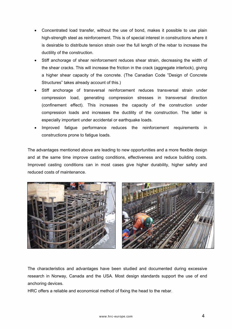
The advantages mentioned above are leading to new opportunities and a more flexible design
and at the same time improve casting conditions, effectiveness and reduce building costs.
Improved casting conditions can in most cases give higher durability, higher safety and
reduced costs of maintenance.
The characteristics and advantages have been studied and documented during excessive
research in Norway, Canada and the USA. Most design standards support the use of end
anchoring devices.
HRC offers a reliable and economical method of fixing the head to the rebar.
5 www.hrc-europe.com
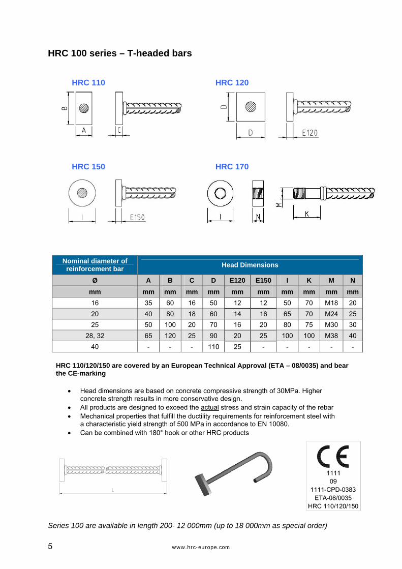
HRC 100 series – T-headed bars
HRC 110 HRC 120
HRC 150 HRC 170
Nominal diameter of reinforcement bar Head Dimensions
Ø A B C D E120 E150 I K M N
mm mm mm mm mm mm mm mm mm mm mm 16 35 60 16 50 12 12 50 70 M18 20 20 40 80 18 60 14 16 65 70 M24 25 25 50 100 20 70 16 20 80 75 M30 30 28, 32 65 120 25 90 20 25 100 100 M38 40 40 - - - 110 25 - - - - - HRC 110/120/150 are covered by an European Technical Approval (ETA – 08/0035) and bear
the CE-marking • Head dimensions are based on concrete compressive strength of 30MPa. Higher
concrete strength results in more conservative design.
• All products are designed to exceed the actual stress and strain capacity of the rebar • Mechanical properties that fulfill the ductility requirements for reinforcement steel with
a characteristic yield strength of 500 MPa in accordance to EN 10080.
• Can be combined with 180° hook or other HRC products
Series 100 are available in length 200- 12 000mm (up to 18 000mm as special order)

www.hrc-europe.com 6
T-headed Bars HRC 100 series – performance
Reduced Congestion with T-Headed Bars:
Avoid installation errors and problems with field tolerances:
Strirrups: Field tolerances reduce anchoring
T-Headed Bars: Full anchorage and good support to bottom bar.
Improved robustness at overload and accidental conditions:
A typical situation in the field - not according to building standards.

7 www.hrc-europe.com
HRC 200 series – T-headed bars for fatigue load
HRC 200 series was developed especially for fatigue performance. It has a special geometry
with forged T-heads and the head-to-bar connection in a distance from the head. The HRC 200 series combines all advantages of the HRC 100 with improved resistance under
fatigue loads (as wave- or traffic loads). HRC 210
HRC 220
Nominal diameter of reinforcement bar Head Dimensions
Ø F G H I J mm mm mm mm mm mm 16 60 30 12 50 12 20 72 40 14 60 14 25 90 45 18 70 16 28, 32 115 64 22 90 20 36, 40 special order • All products are designed to exceed the actual stress and strain capacity of the rebar • Mechanical properties that fulfill the ductility requirements for reinforcement steel with a
characteristic yield strength of 500 MPa in accordance to EN 10080. • Can be combined with 180° hook or other HRC products
Series 200 are available in length 200- 12 000mm (up to 18 000mm as special order)

www.hrc-europe.com 8
T-headed Bars HRC 200 series – performance
The curves underneath show the fatigue performance of HRC 200 series T-headed
reinforcement compared to the design curves for straight and bended bars according to EN
1992-1-1:2004. The design curve for HRC T-heads are the result of a research project
undertaken by SINTEF in Norway (report STF 65 F86088; “Fatigue life of forged and plate
headed anchoring bars”).
The diagram shows that the fatigue performance of HRC 200 series is comparable with that of
straight reinforcement bars and better than the fatigue performance for bended bars. With
other words: substituting bends with HRC 200 T-heads will increase the fatigue performance
significantly.
9 www.hrc-europe.com
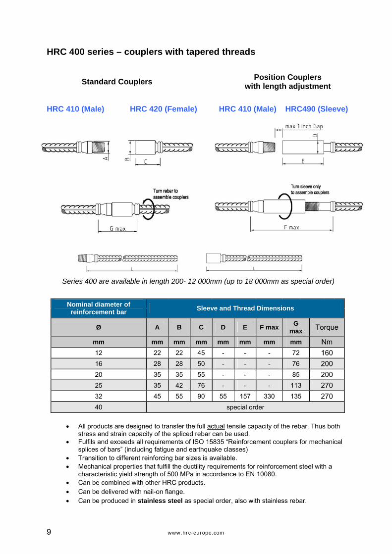
HRC 400 series – couplers with tapered threads
Standard Couplers Position Couplers with length adjustment
HRC 410 (Male) HRC 420 (Female) HRC 410 (Male) HRC490 (Sleeve)
Series 400 are available in length 200- 12 000mm (up to 18 000mm as special order)
Nominal diameter of reinforcement bar Sleeve and Thread Dimensions
Ø A B C D E F max G
max Torque
mm mm mm mm mm mm mm mm Nm 12 22 22 45 - - - 72 160 16 28 28 50 - - - 76 200 20 35 35 55 - - - 85 200 25 35 42 76 - - - 113 270 32 45 55 90 55 157 330 135 270 40 special order • All products are designed to transfer the full actual tensile capacity of the rebar. Thus both
stress and strain capacity of the spliced rebar can be used. • Fulfils and exceeds all requirements of ISO 15835 “Reinforcement couplers for mechanical
splices of bars” (including fatigue and earthquake classes) • Transition to different reinforcing bar sizes is available. • Mechanical properties that fulfill the ductility requirements for reinforcement steel with a
characteristic yield strength of 500 MPa in accordance to EN 10080. • Can be combined with other HRC products. • Can be delivered with nail-on flange. • Can be produced in stainless steel as special order, also with stainless rebar.

www.hrc-europe.com 10
DON’T MAKE THE SPLICE YOUR WEAK LINK!
HRC 410 HRC 420
HRC 490 Position coupler used to connect pre-tied reinforcement.
Use of HRC 410/420 coupler system for slab/wall connection.
HRC 400 Series - Technically Speaking: • Exceeds all international known
requirements for rebar couplers, including reinforcement design specifications for seismic events
• Designed to exceed the actual stress and strain capacity of all reinforcement grades, independent of variable heats
• Behaves like continuous reinforcement and provides full utilization of the strength and ductility properties of the reinforcement
• It will simply put your tensile test failure outside the splicing area and break in the bar
HRC 400 Series - Practically Speaking: • Taper Threads provide a fast, simple
and self-locking installation
• Reliable Quality Control provided by visual inspection and a torque wrench
• HRC 490 Position Coupler - Splice long and high dimension reinforcement without turning the bars
• Less sensitive for tolerances and rough field conditions than any other mechanical coupler
• Excellent for use in casting joints
HRC 120

11 www.hrc-europe.com
HRC 700 series – foundation bolts
HRC 700 Series products come not in certain fixed lengths, but are tailor made to fit projects
needs. Thus they can be an integrated part of the reinforcement.
HRC 710
Thread diameter
Nominal diameter of reinforcing
bar
Thread length HRC 710
T-head1 Characteristic yield-load
Characteristic tensile-load
Ø B H1 A mm mm mm mm mm
kN
kN
M18 16 - 125 200 50 100 115 M20 20 - 125 200 60 110 134 M24 20 - 150 200 60 157 180 M27 25 100 150 250 70 206 252 M30 25 - 150 250 70 245 282 M36 32 - 170 300 90 402 462
1when combined with HRC 120 Series T-head
HRC 720 / HRC 720SS
Thread diameter
Nominal diameter of reinforcing
bar
HRC 720 HRC 720SS2 (stainless steel sleeve,
“black” rebar)
T-head1
Ø C D E C D E H1 A mm mm mm mm mm mm mm mm
M18 20 28 30 50 30 30 60 60 M20 25 35 35 55 38 35 60 70 M24 25 35 40 60 45 40 60 70 M30 32 45 50 70 50 50 70 90 M36 40 55 60 80 - - - 110
1when combined with HRC 120 Series T-head 2special order with possible longer delivery time
Series 700 are available in length 250 - 12 000mm (up to 18 000mm as special order)

www.hrc-europe.com 12
Bearing capacity of HRC 700 Series: For HRC 710 the bearing capacity is given in the table as characteristic yield- and tensile load.
For HRC 720/ HRC 720SS the capacity is at least like a threaded rod of quality 8.8.
Possible combinations: Products of HRC 700 Series can be combined with other HRC-products (T-heads or rebar
couplers) and can be delivered with threaded rods, nuts and washers.
Example of use of HRC 720 Series: (1) Foundation coupler is installed even with the surface of the foundation and cast in. The opening
in the sleeve is closed with a plastic cap to prevent
cement lime or dirt from entering into the sleeve. There
are no protruding part witch can be damaged or could
present a danger.
(2) The treaded part is screwed into the sleeve. Under
combined tension- and shear load the high-strength
material of the bolt will guarantee the necessary
capacity. Maximum allowable tension load is limited by
the capacity of the bolt (up to strength 8.8), but shear
load is restricted by the concrete pressure against the
sleeve.
(3) The outer diameter of the sleeve gives the bolt better
transversal contact against the concrete and therefore a higher shear capacity compared to
cast in threaded rods. Higher capacity in the threaded part can therefore be used to transmit
big shear forces from a footing and down into the concrete.
(4) Screwed in threaded parts make it possible to change damaged parts in an easy way and at
the same time to keep a sound foundation.

13 www.hrc-europe.com
Application: fastening of guardrails on bridges
The Norwegian road administration ”Statens Vegvesen” proposes a new solution for fastening
of poles for guardrails on bridges, poles for traffic signs, lighting masts etc. using HRC-
products. This new solution will ease the construction (saving cost and time) and later the
maintenance of the bridge.
The fastening system uses HRC 300 metric couplers of stainless steel attached to a T-headed
rebar ø20mm. The pole is mounted by M20 bolts leaving a gap of approximately 50mm to the
concrete surface.
The use of the HRC 300 components has several advantages:
- in the construction phase there are no protruding bolts which can be damaged
(the sleeves are protected by plastic plugs from dirt or concrete entering into it)
- it is possible to change the bolts if necessary without any concrete work
- connection between stainless steel (sleeve) and black steel (rebar) possible
- in an accident situation the pole will perform satisfactory as most of the deformation
takes place in the pole, not in the fastening bolts

www.hrc-europe.com 14
Shear reinforcement with T-headed bars T-headed bars are suitable as shear reinforcement in many kinds of constructions.
HRC T-headed bars anchor the full capacity of the rebar in the head only. That means no
hook or bend is necessary for full anchoring of the bar. This makes it possible to avoid
congestion with many thin bars by fewer using bars with large diameter were appropriate. The
installation will speed up and casting conditions are improved securing a good quality of the
finished construction.
HRC T-heads provide full anchoring even when the concrete cover gets lost (f. instance by
accident).
Compared to traditional shear reinforcement, HRC T-headed bars are easier and much faster
to install. This saves construction time, avoids errors in placing and makes the result easy to
control.
T-heads provide a stiffer anchoring of the rebar compared to bends, resulting in smaller crack
widths for shear cracks. Thus an increased aggregate interlock will increase the concrete
contribution to shear strength.
Under in plane compression the T-heads add confinement by head bearing directly against the
concrete core. This is very important for shear walls.
Shear reinforcement with T-headed bars can be calculated with the common methods given in
design standards. The result will be conservative because most design standards do not take
into account the special characteristics of anchorage by T-heads. Today it is only the
Canadian Code CAN/CSA-A23.3-04 “Design of Concrete Structures” which allows an increase
of the factored shear stress resistance of the concrete by 50% if headed shear reinforcement
is used.

15 www.hrc-europe.com
Shear reinforcement - walls
- possible with T-heads on both ends or with one T-head and one
180° hook
- secures full anchoring on both ends
- easy to install
- T-heads providing confinement effect, thus increasing the
strength of the concrete

www.hrc-europe.com 16
Shear reinforcement - massive slabs, foundations
- possible to use bars with large diameter (fewer bars to place)
- secures full anchorage on both ends
- easy and fast to install
- avoids congestion

17 www.hrc-europe.com
T-headed bars in Eurocode
The use of T-headed reinforcement in concrete structures is acknowledged and utilized by
building designers all over the world. Many national building codes allow designers to choose
the option of mechanical anchorages, such as T-headed bars.
The development of a European standard for the design of concrete structures is finished now.
National standards will be replaced by the EN 1992 “Eurocode 2: Design of concrete
structures” together with a national annex.
The use of T-headed bars is principally allowed by this design standard.
EN 1992-1-1:2004 states in chapter 8.4 “Anchorage of longitudinal reinforcement”:
8.4.1 (5) “Where mechanical devices are used the test requirements should be in accordance
with the relevant product standard or a European Technical Approval.”
For reinforcing bars with large diameter the use of anchoring devises as T-heads is
recommended. Chapter 8.8 “Additional rules for large diameter bars” says:
8.8 (3) “...Such bars should be anchored with mechanical devices.”
HRC 100 series T-headed bars have
a European Technical Approval and
can therefore be used
when designing with EN 1992-1-1.
HRC 110, HRC 120 and HRC 150 bear the
CE-marking and can as a construction product
move freely within the EU & EFTA internal
market.

www.hrc-europe.com 18
T-headed bars and Strut-and-Tie-modelling
The Eurocode EN 1992-1-1 allows the use of strut and tie models (see chapter 5.6.4 of the
standard). Strut-and-tie modelling is a detailing and ultimate strength calculation method for
discontinuity regions of reinforced concrete structures, such as abrupt changes of cross-
section or locations with point loads (discontinuity regions as half joints, supports, corbels
etc.).
Strut-and-tie-modelling is based on the construction of a virtual truss mechanism within the
outline of the member to be analyzed. The truss mechanism consists of struts that model
concrete compression fields, ties that model the tensile steel reinforcement and nodes that
represent areas in witch tensile steel is anchored into the concrete and strut forces are
transferred into the ties.
Because of the modelling of the transfer-areas as nodes, there is only limited space for the
anchoring of the reinforcement. The use of T-headed reinforcement provides clearly defined
nodes for the analysis, thus securing safe design.
HRC T-heads are capable to anchor the full capacity of the rebar in the head alone.
That gives the following advantages when using strut-and-tie modelling:
- Reinforcing bars are anchored in a defined point - the T-head. Thus a broad
coincidence of the real structure with the model is achieved.
- It is possible to design the construction with smaller dimensions because of the space
saving type of anchoring of the rebar.
- T-headed bars are easy and quick to place, speeding up construction and better the
possibilities for control.
- Due to the possibility of using larger bar diameters congestion is avoided, improving
the casting conditions and ensuring god quality of the finished product.
19 www.hrc-europe.com
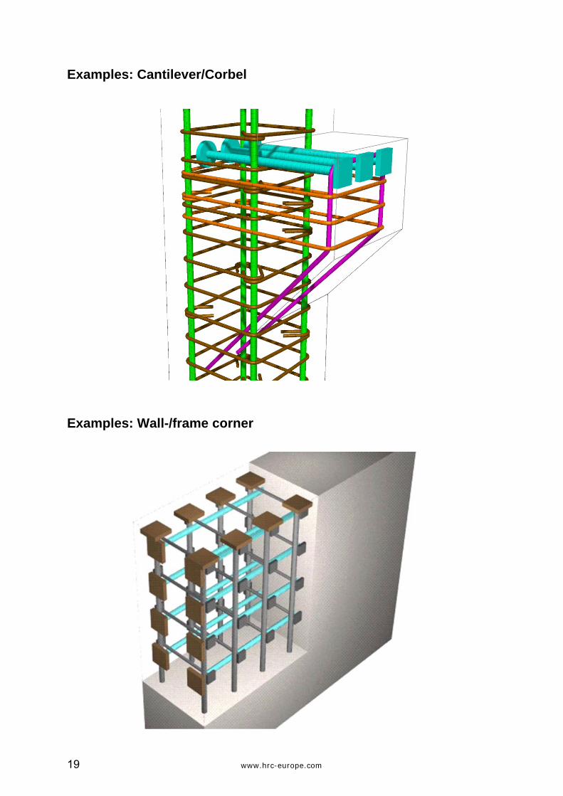
Examples: Cantilever/Corbel
Examples: Wall-/frame corner
www.hrc-europe.com 20
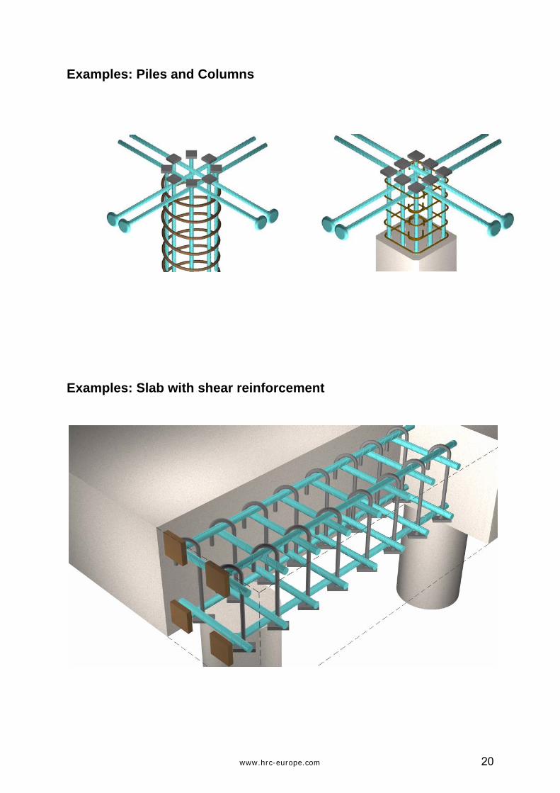
Examples: Piles and Columns
Examples: Slab with shear reinforcement

21 www.hrc-europe.com
Examples: Pile caps

www.hrc-europe.com 22
Example: Use in multi-storey buildings Top slab: Anchorage of wall- or column reinforcement by T-heads avoids rebar protruding sideways, hampering the lift out of the wall- /column boarding and the placing of the formwork for the slab.
Intermediate floor slab: Wall- or column reinforcement is spliced by HRC reinforcement couplers. The slab can be reinforced fast and efficient because there are no long protruding rebar.
Base slab: The reinforcement for the base slab can be placed completely before starting with the reinforcement for walls or columns. Using T-headed bars makes it possible to place starter bars into the finished reinforcement of the slab. One has flexibility because the T-heads don’t need a crossing bar for anchorage (anchorage by T-head alone).
HRC T-headed bars and mechanical couplers are well suited for application together with reinforcement on rolls.
23 www.hrc-europe.com
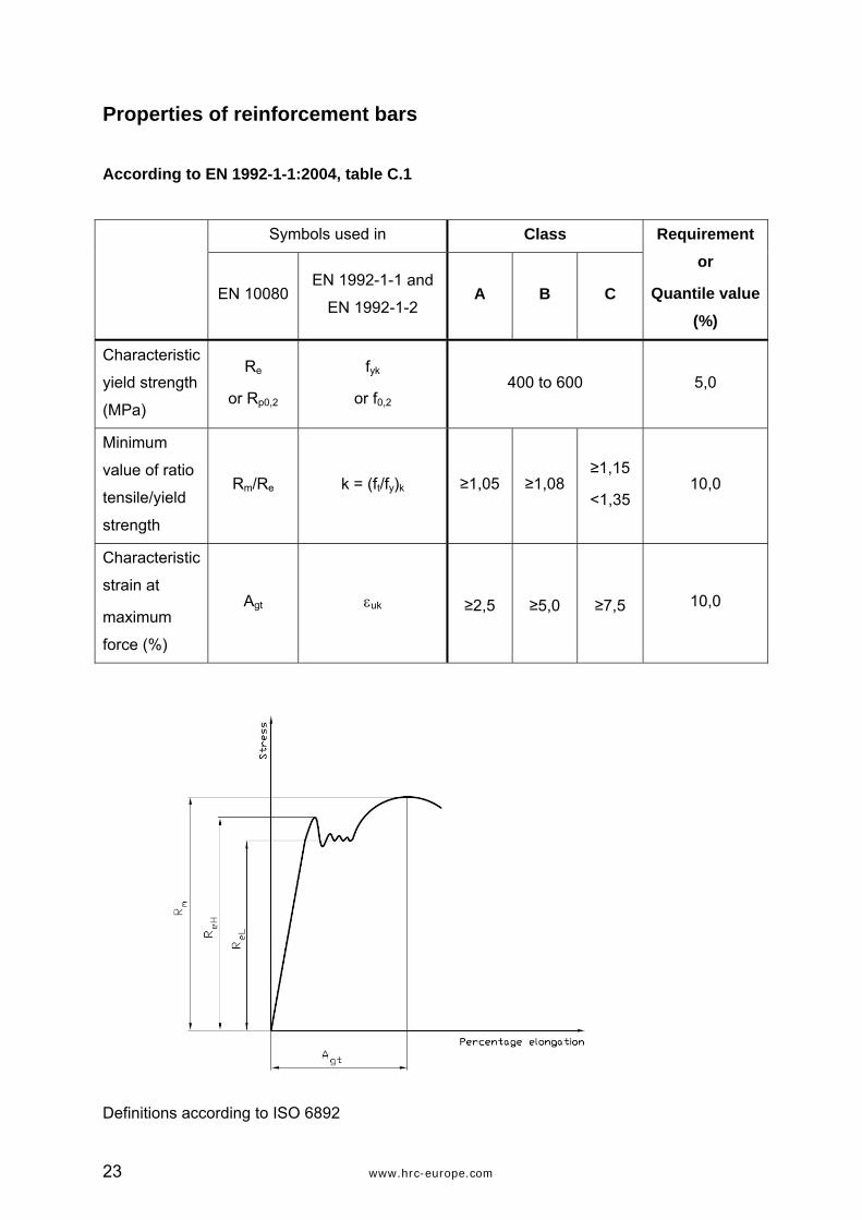
Properties of reinforcement bars According to EN 1992-1-1:2004, table C.1
Symbols used in Class
EN 10080 EN 1992-1-1 and
EN 1992-1-2 A B C
Requirement or
Quantile value (%)
Characteristic
yield strength
(MPa)
Re
or Rp0,2
fyk
or f0,2 400 to 600 5,0
Minimum
value of ratio
tensile/yield
strength
Rm/Re k = (ft/fy)k ≥1,05 ≥1,08 ≥1,15
<1,35 10,0
Characteristic
strain at
maximum
force (%)
Agt εuk ≥2,5 ≥5,0 ≥7,5 10,0
Definitions according to ISO 6892

www.hrc-europe.com 24
The data and commentary provided within this document is for general information purpose only. It is
provided without warranty of any kind. HRC-Metalock Industrier AS shall not be held responsible for any
errors, omissions or misuse of any of the enclosed information and hereby disclaims any and all liability
resulting form the ability or inability to use the information contained within.
en 4/10

25 www.hrc-europe.com
HRC – Metalock Industrier AS
PO box 591, N-3412 Lierstranda, Norway
Tel: +(47) 32 24 04 70
Fax: +(47) 32 84 00 56
[email protected] HRC USA:
www.hrc-europe.com www.hrc-usa.com