product catalogue gas-insulated ring main unit and gas ... · • iec 62271-102: alternating...
TRANSCRIPT
—
Gas
-ins
ulat
ed r
ing
mai
n un
it a
ndga
s-in
sula
ted
com
pact
sw
itch
gear
Saf
eRin
g/S
afeP
lus
12-2
4 k
V
—PRODUCT CATALOGUE
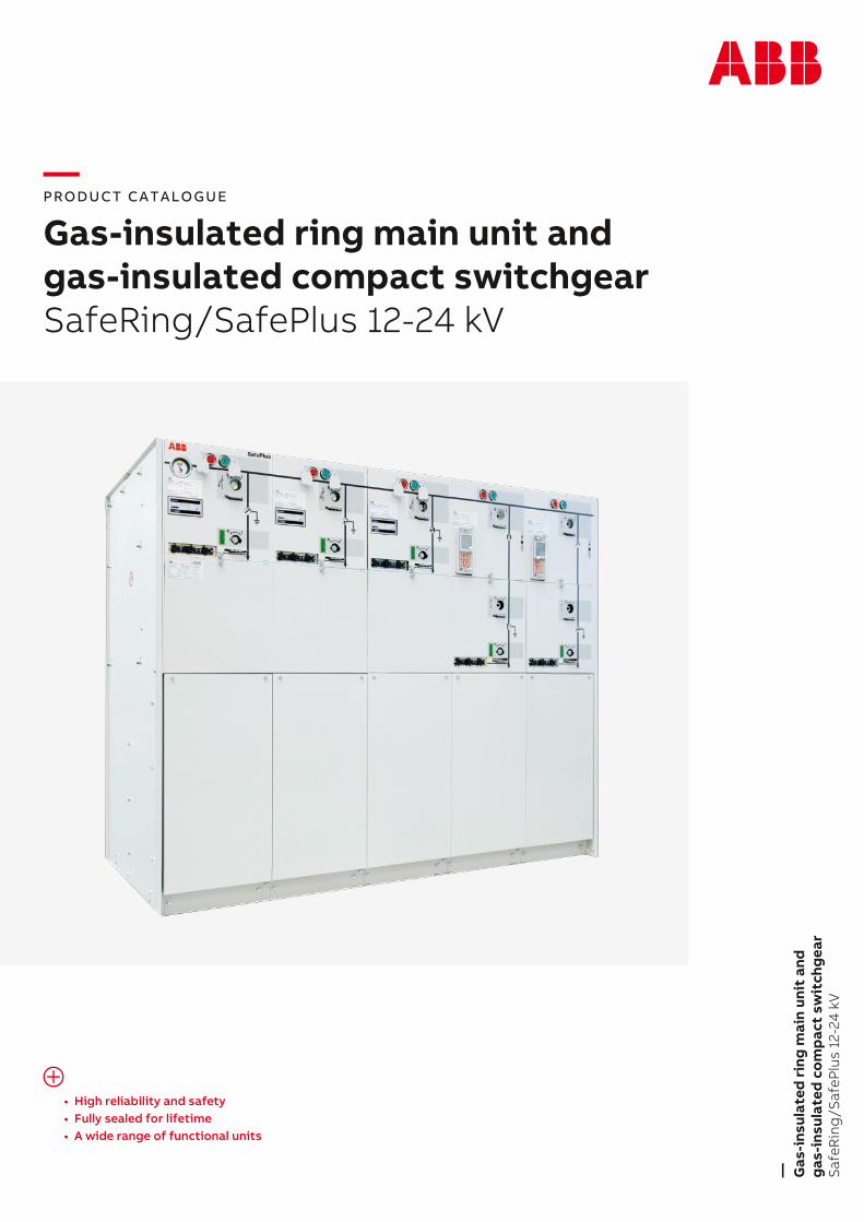
Gas-insulated ring main unit andgas-insulated compact switchgearSafeRing/SafePlus 12-24 kV
• High reliability and safety• Fully sealed for lifetime• A wide range of functional units

—Table of contents
005 – 007
008 – 009
010
011
012 – 013
014 – 018
019
020 – 026
027 – 049
050
051
052 – 053
054 – 056
057
058 – 059
060
1 Introduction
2 Design philosophy
3 Outer assembly
4 Inner design
5 Production
6 Safety
7 Applications SafeRing/ SafePlus
8 Applications SafeRing
9 SafePlus modules
10 Mini-metering (integrated metering)
11 Combisensor
12 SeSmart
13 Mechanisms
14 Cable bushings
15 Cable termination
16 Cable test bushings
17 Extension of switchgear
18 Base frame
19 Low voltage compartment/ top entry box
20 Motor operation
21 Transformer protection
22 Fuse-links
23 Relays
24 Capacitive voltage indicators
25 Short-circuit indicators
26 Manometers/pressure indicators
27 Key interlocks
28 Smart grid applications
29 Low version switchgear
30 Dimensions
31 Technical data
32 Environmental certification
061 – 062
063
064
065 – 066
067
068 – 070
071 – 076
077 – 078
079
080
081– 082
083 – 087
088
089 – 096
097 – 103
104
005 – 007
008 – 009
010
011
012 – 013
014 – 018
019
020 – 026
027 – 049
050
051
052 – 053
054 – 056
057
058 – 059
060
1 Introduction
2 Design philosophy
3 Outer assembly
4 Inner design
5 Production
6 Safety
7 Applications SafeRing/ SafePlus
8 Applications SafeRing
9 SafePlus modules
10 Mini-metering (integrated metering)
11 Combisensor
12 SeSmart
13 Mechanisms
14 Cable bushings
15 Cable termination
16 Cable test bushings
4 G A S - I N S U L A T E D R I N G M A I N U N I T A N D G A S - I N S U L A T E D C O M P A C T S W I T C H G E A R P R O D U C T C A T A L O G U E
17 Extension of switchgear
18 Base frame
19 Low voltage compartment/ top entry box
20 Motor operation
21 Transformer protection
22 Fuse-links
23 Relays
24 Capacitive voltage indicators
25 Short-circuit indicators
26 Manometers/pressure indicators
27 Key interlocks
28 Smart grid applications
29 Low version switchgear
30 Dimensions
31 Technical data
32 Environmental certification
061 – 062
063
064
065 – 066
067
068 – 070
071 – 076
077 – 078
079
080
081– 082
083 – 087
088
089 – 096
097 – 103
104
—1 Introduction
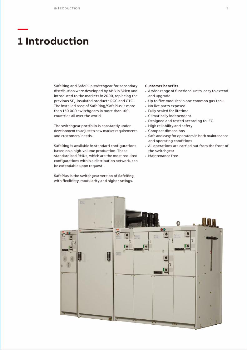
SafeRing and SafePlus switchgear for secondary distribution were developed by ABB in Skien and introduced to the markets in 2000, replacing the previous SF6-insulated products RGC and CTC. The installed base of SafeRing/SafePlus is more than 150,000 switchgears in more than 100 countries all over the world.
The switchgear portfolio is constantly under development to adjust to new market requirements and customers’ needs.
SafeRing is available in standard configurations based on a high-volume production. These standardized RMUs, which are the most required configurations within a distribution network, can be extendable upon request.
SafePlus is the switchgear version of SafeRing with flexibility, modularity and higher ratings.
Customer benefits• A wide range of functional units, easy to extend
and upgrade• Up to five modules in one common gas tank• No live parts exposed• Fully sealed for lifetime• Climatically independent• Designed and tested according to IEC• High reliability and safety• Compact dimensions• Safe and easy for operators in both maintenance
and operating conditions• All operations are carried out from the front of
the switchgear• Maintenance free
I N T R O D U C T I O N 5
6 G A S - I N S U L A T E D R I N G M A I N U N I T A N D G A S - I N S U L A T E D C O M P A C T S W I T C H G E A R P R O D U C T C A T A L O G U E
Applicable standardsSafeRing/SafePlus is tested according to following IEC-standards:• IEC 62271–1: Specifications High-voltage
switchgear• IEC 62271-100: Alternating-current circuit-breakers• IEC 62271-102: Alternating current disconnectors
earthing switches• IEC 62271-103: High-voltage switches• IEC 62271-105: Switch-fuse co-operation• IEC 62271-200: Arc fault and switchgear• IEC 60529: Degrees of protection provided by
enclosures
SafeRing/SafePlus is also tested together with CSS according to IEC 62271-202 standard. Tests have been performed on CSS from various manufacturers.
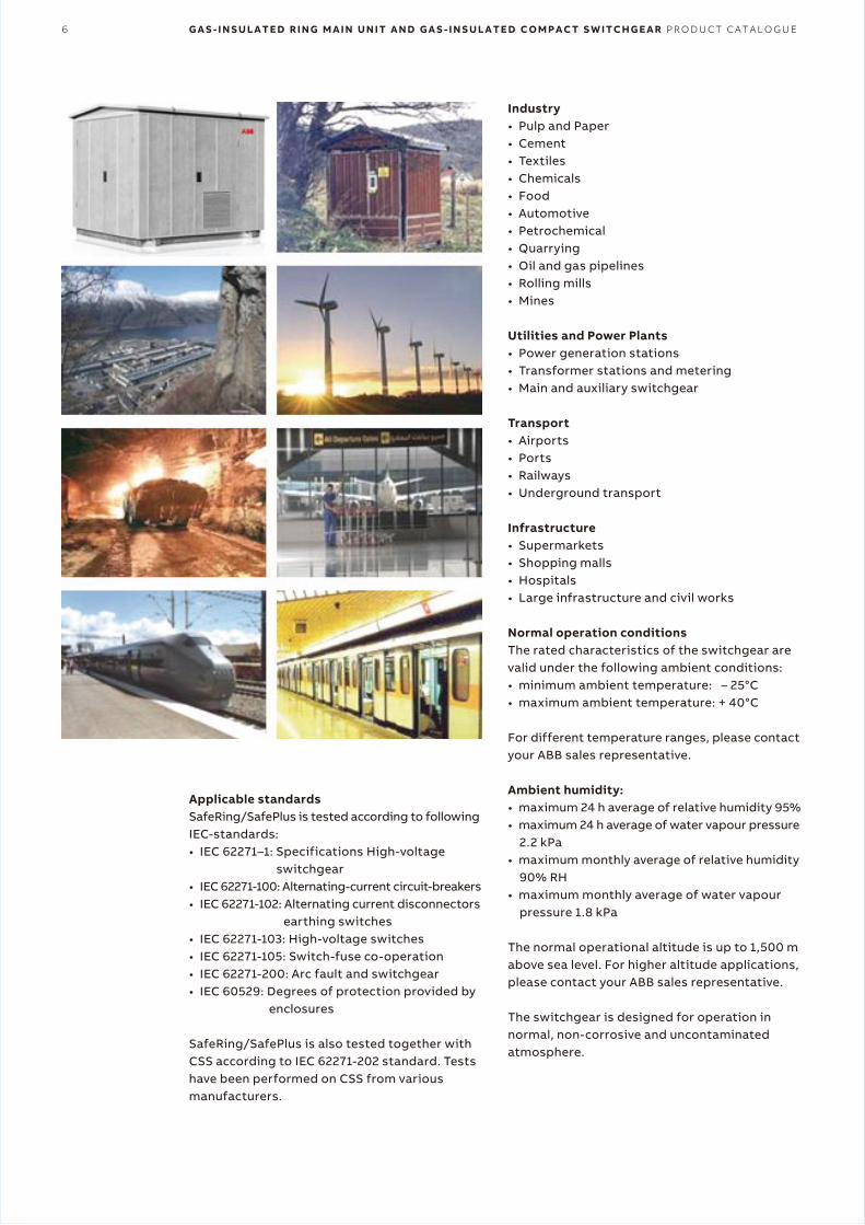
Industry• Pulp and Paper• Cement• Textiles• Chemicals• Food• Automotive• Petrochemical• Quarrying• Oil and gas pipelines• Rolling mills• Mines
Utilities and Power Plants• Power generation stations• Transformer stations and metering• Main and auxiliary switchgear
Transport• Airports• Ports• Railways• Underground transport
Infrastructure• Supermarkets• Shopping malls• Hospitals• Large infrastructure and civil works
Normal operation conditionsThe rated characteristics of the switchgear are valid under the following ambient conditions:• minimum ambient temperature: – 25°C• maximum ambient temperature: + 40°C
For different temperature ranges, please contact your ABB sales representative.
Ambient humidity:• maximum 24 h average of relative humidity 95%• maximum 24 h average of water vapour pressure
2.2 kPa• maximum monthly average of relative humidity
90% RH• maximum monthly average of water vapour
pressure 1.8 kPa
The normal operational altitude is up to 1,500 m above sea level. For higher altitude applications, please contact your ABB sales representative.
The switchgear is designed for operation in normal, non-corrosive and uncontaminated atmosphere.
I N T R O D U C T I O N 7
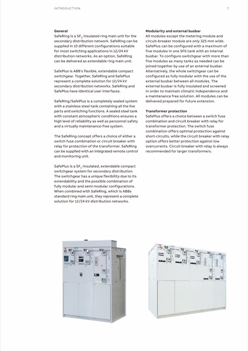
GeneralSafeRing is a SF6-insulated ring main unit for the secondary distribution network. SafeRing can be supplied in 10 different configurations suitable for most switching applications in 12/24 kV distribution networks. As an option, SafeRing can be delivered as extendable ring main unit.
SafePlus is ABB’s flexible, extendable compact switchgear. Together, SafeRing and SafePlus represent a complete solution for 12/24 kV secondary distribution networks. SafeRing and SafePlus have identical user interfaces.
SafeRing/SafePlus is a completely sealed system with a stainless steel tank containing all the live parts and switching functions. A sealed steel tank with constant atmospheric conditions ensures a high level of reliability as well as personnel safety and a virtually maintenance-free system.
The SafeRing concept offers a choice of either a switch fuse combination or circuit breaker with relay for protection of the transformer. SafeRing can be supplied with an integrated remote control and monitoring unit.
SafePlus is a SF6-insulated, extendable compact switchgear system for secondary distribution. The switchgear has a unique flexibility due to its extendability and the possible combination of fully modular and semi modular configurations.When combined with SafeRing, which is ABBs standard ring main unit, they represent a complete solution for 12/24 kV distribution networks.
Modularity and external busbarAll modules except the metering module and circuit-breaker module are only 325 mm wide.SafePlus can be configured with a maximum of five modules in one SF6 tank with an internal busbar. To configure switchgear with more than five modules as many tanks as needed can be joined together by use of an external busbar. Alternatively, the whole switchgear can be configured as fully modular with the use of the external busbar between all modules. The external busbar is fully insulated and screened in order to maintain climatic independence and a maintenance free solution. All modules can be delivered prepared for future extension.
Transformer protectionSafePlus offers a choice between a switch fuse combination and circuit breaker with relay for transformer protection. The switch fuse combination offers optimal protection againstshort-circuits, while the circuit breaker with relay option offers better protection against low overcurrents. Circuit breaker with relay is always recommended for larger transformers.

8 G A S - I N S U L A T E D R I N G M A I N U N I T A N D G A S - I N S U L A T E D C O M P A C T S W I T C H G E A R P R O D U C T C A T A L O G U E
—2 Design philosophy
SafeRing and SafePlus – ABB switchgear for secondary distributionSecondary distribution switchgears have been subject to a significant development the past 20 years, resulting in increased functionality and smaller dimensions.
The traditional switching cells are substituted with complete switchgear systems. Specific functions such as grounding, disconnecting, cable connections, busbar extension, protectionand switching have become integrated features in compact functional units.
Compact switchgear systems meet customers’ MV application needs. ABB has always been a part of this development.
The current ABB SafePlus range satisfies the most complex system specifications.
The most unique specialization is the development of the cable ring switchgear. The numerous public distribution substations requested a unified switching functionality which evolved into the ring main unit concept.
ABB SafeRing range is one major contributor to this specialization.
Two Products – one rangeABB SafeRing is adapted to the needs in the immense utility distribution network.
ABB SafePlus offers more in terms of flexibility and electrical capacity.
Both switchgear offer the same customer interface.
Customers’ involvementThe applied functionality in ABB SafeRing and SafePlus is a result of input from customers all over the world.
Key customers are continuously involved with ABB design staff to ensure optimized switchgear operation. The functionality will always find its background from customer demands.
Personnel – safety and serviceSafety is not only a specification and rating issue, but also a real life experience.
Standards and associated testing will disclose weakness at the time of testing. ABB takes this further to be an objective related to durability and repetitive manufacturing quality.
All products are manufactured in accordance with ISO 9001. The latest edition of relevant IEC standards will always apply to our continuous product development and test program. “Integrated functionality” is a key objective to reduce the number of moving components, further reducing the risk of any mechanical defect.
We are responsible for the environmentThe location for manufacturing SafeRing and SafePlus is Norway. Norway’s green policy contributes to focus on environmental factors in manufacturing as well as over the switchgears life span.
All products are manufactured in accordance with our ISO 14001 certification.
Recycling is confirmed at a 97% level.
To simplify this process, we will continuously work with our partners to develop routines for handling end of life.
Plastic parts are individually marked to simplify the recycling process.
Solutions for elimination of gas emission in the rare event of a fault can be supplied.
Modern – development and manufacturingNumerical simulations together with long experience will ensure compact and robust design.
Dielectric simulations will ensure that compactness will not influence the dielectric capability.
The combination of design techniques, experience
and the most modern production technology guarantee state of the art products and durability.
Complete solutions – one supplierComplex applications involving different standard remote levels, such as monitoring, control measurement and protection can now be supplied from one supplier. This makes large scale implementation feasible and will simplify engineering and procurement.The control and monitoring unit available for SafeRing is located behind the front cover. This option is also readily available for retrofitsince such demands normally evolve after the switchgear is in service.
D E S I G N P H I L O S O P H Y 9
SafeRing and SafePlus – ABB switchgear for secondary distributionSecondary distribution switchgears have been subject to a significant development the past 20 years, resulting in increased functionality and smaller dimensions.
The traditional switching cells are substituted with complete switchgear systems. Specific functions such as grounding, disconnecting, cable connections, busbar extension, protectionand switching have become integrated features in compact functional units.
Compact switchgear systems meet customers’ MV application needs. ABB has always been a part of this development.
The current ABB SafePlus range satisfies the most complex system specifications.
The most unique specialization is the development of the cable ring switchgear. The numerous public distribution substations requested a unified switching functionality which evolved into the ring main unit concept.
ABB SafeRing range is one major contributor to this specialization.
Two Products – one rangeABB SafeRing is adapted to the needs in the immense utility distribution network.
ABB SafePlus offers more in terms of flexibility and electrical capacity.
Both switchgear offer the same customer interface.
Customers’ involvementThe applied functionality in ABB SafeRing and SafePlus is a result of input from customers all over the world.
Key customers are continuously involved with ABB design staff to ensure optimized switchgear operation. The functionality will always find its background from customer demands.
Personnel – safety and serviceSafety is not only a specification and rating issue, but also a real life experience.
Standards and associated testing will disclose weakness at the time of testing. ABB takes this further to be an objective related to durability and repetitive manufacturing quality.
All products are manufactured in accordance with ISO 9001. The latest edition of relevant IEC standards will always apply to our continuous product development and test program. “Integrated functionality” is a key objective to reduce the number of moving components, further reducing the risk of any mechanical defect.
We are responsible for the environmentThe location for manufacturing SafeRing and SafePlus is Norway. Norway’s green policy contributes to focus on environmental factors in manufacturing as well as over the switchgears life span.
All products are manufactured in accordance with our ISO 14001 certification.
Recycling is confirmed at a 97% level.
To simplify this process, we will continuously work with our partners to develop routines for handling end of life.
Plastic parts are individually marked to simplify the recycling process.
Solutions for elimination of gas emission in the rare event of a fault can be supplied.
Modern – development and manufacturingNumerical simulations together with long experience will ensure compact and robust design.
Dielectric simulations will ensure that compactness will not influence the dielectric capability.
The combination of design techniques, experience
and the most modern production technology guarantee state of the art products and durability.
Complete solutions – one supplierComplex applications involving different standard remote levels, such as monitoring, control measurement and protection can now be supplied from one supplier. This makes large scale implementation feasible and will simplify engineering and procurement.The control and monitoring unit available for SafeRing is located behind the front cover. This option is also readily available for retrofitsince such demands normally evolve after the switchgear is in service.

10 G A S - I N S U L A T E D R I N G M A I N U N I T A N D G A S - I N S U L A T E D C O M P A C T S W I T C H G E A R P R O D U C T C A T A L O G U E
—3 Outer assembly
Upper front cover1. Manometer2. Nameplate module3. Short circuit indicator4. Capacitive voltage indication5. Load break/earthing switch position indicator6. Push buttons close/open operation7. Charged spring indicator8. Self-powered protection relay9. Vacuum circuit-breaker position10. Operation shaft11. Padlock device
Lower front cover12. Nameplate switchgear13. Fuse blown indicator14. Disconnector/earthing switch position
indicator15. Capacitive voltage indication
��� SafePlus
19
10 11
1
2
3
4
12
13
5 6 7 8
9
20
14
15
16
18
17
Cable compartment cover16. Cable compartment cover standard17. Cable compartment cover with inspection
window18. Support bar (removable)
Side cover19. Lifting lug20. Operating handle (standard on right hand side)

I N N E R D E S I G N 11
—4 Inner design
1. Mechanism compartment2. SF6 gas tank3. Cable compartment4. Pressure relief area
1
2
3
4
12 G A S - I N S U L A T E D R I N G M A I N U N I T A N D G A S - I N S U L A T E D C O M P A C T S W I T C H G E A R P R O D U C T C A T A L O G U E
—5 Production
5.1 Completely sealed systemExterior constructionUpper and lower front cover have a thickness of 3 mm aluminium which is covered with a polycarbonate foil. These foils contain the mimic diagram of the main circuit integrated with the position indicators for the switching devices. Background colour for these foils is light grey (RAL 7035). The upper front cover is removable. The lower front cover can be opened.
There are four different cable compartment covers: standard, with inspection window, arc proof and with extra depth for parallel cables. These covers are manufactured from 1.5 mm aluzink (except the arc proof cover) and are powder painted with colour RAL 7035.
All cable compartment covers are removable. Each module has a separate cable compartment which is divided from the others by means of partition walls. These partition walls can easily be removed, allowing a comfortable access for connection of cables.
A vertical partition wall is fitted to divide the cable compartment(s) from the rear side of the switchgear/ring main unit.
In case of an arc fault inside the SF6 tank, followed by an opening of the pressure relief in the bottom of the tank, this partition wall will prevent the hot gases blowing out from the pressure relief to enter the cable compartments.
Side covers are made of 2 millimeter hot rolled steel and powder painted with colour RAL 7035.
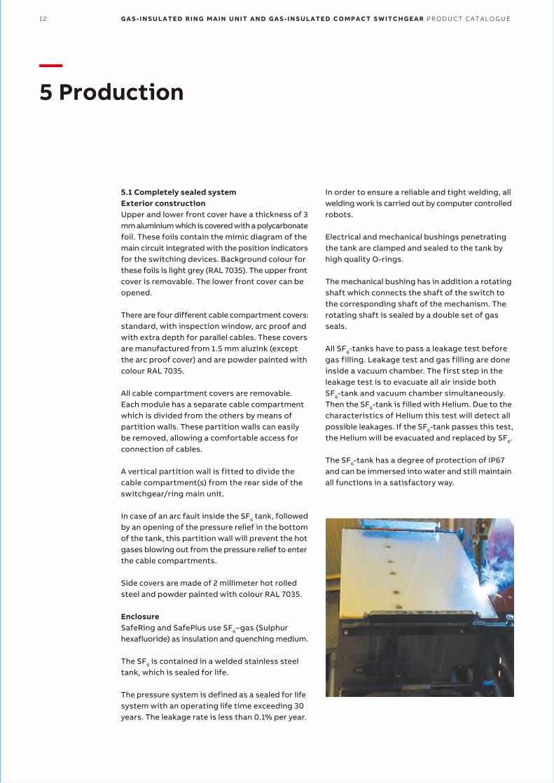
EnclosureSafeRing and SafePlus use SF6–gas (Sulphur hexafluoride) as insulation and quenching medium.
The SF6 is contained in a welded stainless steel tank, which is sealed for life.
The pressure system is defined as a sealed for life system with an operating life time exceeding 30 years. The leakage rate is less than 0.1% per year.
In order to ensure a reliable and tight welding, all welding work is carried out by computer controlled robots.
Electrical and mechanical bushings penetrating the tank are clamped and sealed to the tank by high quality O-rings.
The mechanical bushing has in addition a rotating shaft which connects the shaft of the switch to the corresponding shaft of the mechanism. The rotating shaft is sealed by a double set of gas seals.
All SF6-tanks have to pass a leakage test before gas filling. Leakage test and gas filling are done inside a vacuum chamber. The first step in the leakage test is to evacuate all air inside both SF6-tank and vacuum chamber simultaneously.Then the SF6-tank is filled with Helium. Due to the characteristics of Helium this test will detect all possible leakages. If the SF6-tank passes this test, the Helium will be evacuated and replaced by SF6.
The SF6-tank has a degree of protection of IP67 and can be immersed into water and still maintain all functions in a satisfactory way.
P R O D U C T I O N 13
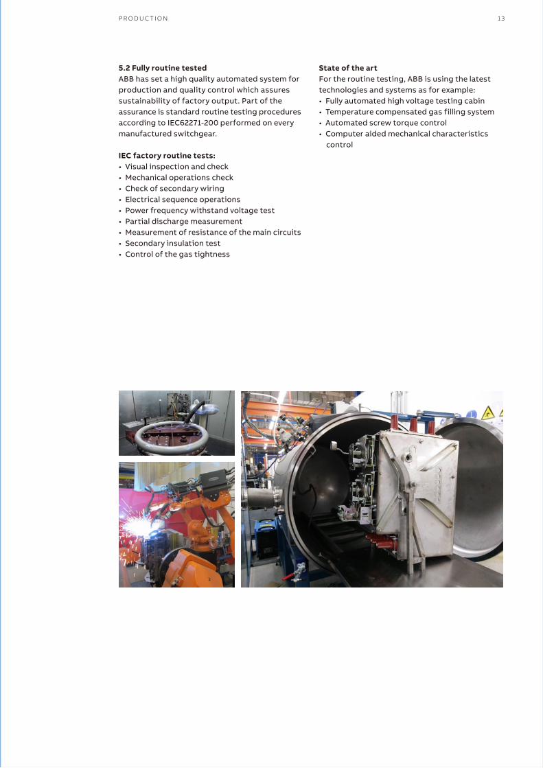
5.2 Fully routine testedABB has set a high quality automated system for production and quality control which assures sustainability of factory output. Part of the assurance is standard routine testing procedures according to IEC62271-200 performed on every manufactured switchgear.
IEC factory routine tests:• Visual inspection and check• Mechanical operations check• Check of secondary wiring• Electrical sequence operations• Power frequency withstand voltage test• Partial discharge measurement• Measurement of resistance of the main circuits• Secondary insulation test• Control of the gas tightness
State of the artFor the routine testing, ABB is using the latest technologies and systems as for example:• Fully automated high voltage testing cabin• Temperature compensated gas filling system• Automated screw torque control• Computer aided mechanical characteristics
control
14 G A S - I N S U L A T E D R I N G M A I N U N I T A N D G A S - I N S U L A T E D C O M P A C T S W I T C H G E A R P R O D U C T C A T A L O G U E
—6 Safety
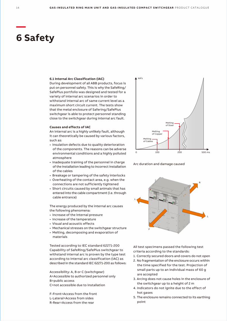
6.1 Internal Arc Classification (IAC)During development of all ABB products, focus is put on personnel safety. This is why the SafeRing/ SafePlus portfolio was designed and tested for a variety of internal arc scenarios in order to withstand internal arc of same current level as a maximum short circuit current. The tests show that the metal enclosure of Safering/SafePlus switchgear is able to protect personnel standing close to the switchgear during internal arc fault.
Causes and effects of IACAn internal arc is a highly unlikely fault, although it can theoretically be caused by various factors, such as:• Insulation defects due to quality deterioration
of the components. The reasons can be adverse environmental conditions and a highly polluted atmosphere
• Inadequate training of the personnel in charge of the installation leading to incorrect installation of the cables
• Breakage or tampering of the safety interlocks• Overheating of the contact area, e.g. when the
connections are not sufficiently tightened• Short circuits caused by small animals that has
entered into the cable compartment (i.e. through cable entrance)
The energy produced by the internal arc causes the following phenomena:• Increase of the internal pressure• Increase of the temperature• Visual and acoustic effects• Mechanical stresses on the switchgear structure• Melting, decomposing and evaporation of
materials
Tested according to IEC standard 62271-200Capability of SafeRing/SafePlus switchgear to withstand internal arc is proven by the type test according to Internal arc classification (IAC) as described in the standard IEC 62271-200 as follows:
Accessibility: A, B or C (switchgear)A=Accessible to authorized personnel onlyB=public accessC=not accessible due to installation
F-Front=Access from the frontL-Lateral=Access from sidesR-Rear=Access from the rear
Meltingof Steel
Meltingof Copper
Melting of Cables
0 100 200 500 ms
kA2s
All test specimens passed the following test criteria according to the standards:1. Correctly secured doors and covers do not open2. No fragmentation of the enclosure occurs within
the time specified for the test. Projection of small parts up to an individual mass of 60 g are accepted
3. Arcing does not cause holes in the enclosure of the switchgear up to a height of 2 m
4. Indicators do not ignite due to the effect of hot gases
5. The enclosure remains connected to its earthing point
R
L
L
F
Arc duration and damage caused
S A F E T Y 15
SafeRing/SafePlus is available for a wide range of installations and applications in order to secure the highest safety for operators. Switchgears are designed and type-tested for internal arc classification according to the following configurations.
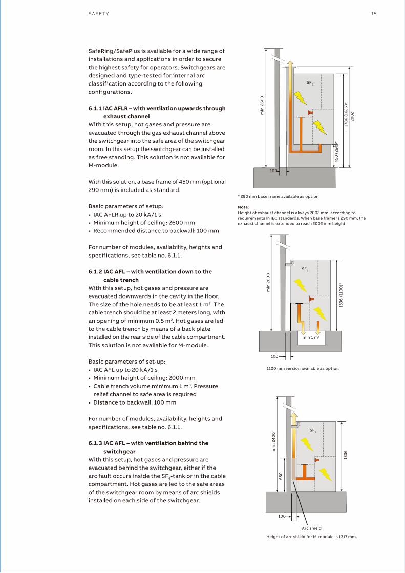
6.1.1 IAC AFLR – with ventilation upwards through exhaust channel
With this setup, hot gases and pressure are evacuated through the gas exhaust channel above the switchgear into the safe area of the switchgear room. In this setup the switchgear can be installed as free standing. This solution is not available for M-module.
With this solution, a base frame of 450 mm (optional 290 mm) is included as standard.
Basic parameters of setup:• IAC AFLR up to 20 kA/1 s• Minimum height of ceiling: 2600 mm• Recommended distance to backwall: 100 mm
For number of modules, availability, heights and specifications, see table no. 6.1.1.
6.1.2 IAC AFL – with ventilation down to the cable trench
With this setup, hot gases and pressure are evacuated downwards in the cavity in the floor. The size of the hole needs to be at least 1 m3. The cable trench should be at least 2 meters long, with an opening of minimum 0.5 m2. Hot gases are led to the cable trench by means of a back plate installed on the rear side of the cable compartment. This solution is not available for M-module.
Basic parameters of set-up:• IAC AFL up to 20 kA/1 s• Minimum height of ceiling: 2000 mm• Cable trench volume minimum 1 m3. Pressure
relief channel to safe area is required• Distance to backwall: 100 mm
For number of modules, availability, heights and specifications, see table no. 6.1.1.
6.1.3 IAC AFL – with ventilation behind the switchgear
With this setup, hot gases and pressure are evacuated behind the switchgear, either if the arc fault occurs inside the SF6-tank or in the cable compartment. Hot gases are led to the safe areas of the switchgear room by means of arc shields installed on each side of the switchgear.
* 290 mm base frame available as option.
Note:Height of exhaust channel is always 2002 mm, according to requirements in IEC standards. When base frame is 290 mm, the exhaust channel is extended to reach 2002 mm height.
SF6
min
24
00
1336
650
100
SF6
450
(29
0)*
200
2
178
6 (
1626
)*
min
26
00
100
SF6m
in 2
00
0
1336
(11
00
)*min 1 m3
100
1100 mm version available as option
Basic parameters of setup:• IAC AFL up to 20 kA/1 s• Minimum height of ceiling: 2400 mm• Distance to backwall: 100 mm• Distance from sidewall: 20 mm. If installed
more than 20 mm from sidewall, an arc shield is required
Arc shield
Height of arc shield for M-module is 1317 mm.

16 G A S - I N S U L A T E D R I N G M A I N U N I T A N D G A S - I N S U L A T E D C O M P A C T S W I T C H G E A R P R O D U C T C A T A L O G U E
SafeRing/SafePlus is available for a wide range of installations and applications in order to secure the highest safety for operators. Switchgears are designed and type-tested for internal arc classification according to the following configurations.
6.1.1 IAC AFLR – with ventilation upwards through exhaust channel
With this setup, hot gases and pressure are evacuated through the gas exhaust channel above the switchgear into the safe area of the switchgear room. In this setup the switchgear can be installed as free standing. This solution is not available for M-module.
With this solution, a base frame of 450 mm (optional 290 mm) is included as standard.
Basic parameters of setup:• IAC AFLR up to 20 kA/1 s• Minimum height of ceiling: 2600 mm• Recommended distance to backwall: 100 mm
For number of modules, availability, heights and specifications, see table no. 6.1.1.
6.1.2 IAC AFL – with ventilation down to the cable trench
With this setup, hot gases and pressure are evacuated downwards in the cavity in the floor. The size of the hole needs to be at least 1 m3. The cable trench should be at least 2 meters long, with an opening of minimum 0.5 m2. Hot gases are led to the cable trench by means of a back plate installed on the rear side of the cable compartment. This solution is not available for M-module.
Basic parameters of set-up:• IAC AFL up to 20 kA/1 s• Minimum height of ceiling: 2000 mm• Cable trench volume minimum 1 m3. Pressure
relief channel to safe area is required• Distance to backwall: 100 mm
For number of modules, availability, heights and specifications, see table no. 6.1.1.
6.1.3 IAC AFL – with ventilation behind the switchgear
With this setup, hot gases and pressure are evacuated behind the switchgear, either if the arc fault occurs inside the SF6-tank or in the cable compartment. Hot gases are led to the safe areas of the switchgear room by means of arc shields installed on each side of the switchgear.
—Table 6.1.1
1) Height of exhaust channel is 2002 mm. This dimension is independent of the height of the base frame. If base frame is 290 mm, exhaust channel is extended to reach 2002 mm.
2) In case two sets of CT’s are required, additional base frame is mandatory. Second set of CT’s will be installed in base frame.
3) IAC classification is unavailable in case of use of gland plates.4) If base frame is added, roof height needs to be 2400 mm.5) Not allowed with gland plate between switchgear and base frame,
gland plate can be installed below base frame.6) 290 mm base frame as option.
ISC
(kA/1s)
16
20
IAC
class
AFL
AFL
AFLR
AFL
AFL
AFLR
Ventilation
Backwards
Downwards 3)
Upwards 5)
Backwards
Downwards 3)
Upwards 5)
Height of
switchgear
(mm)
1336 (standard)
1100 (low)
1336 (standard)
1100 (low)
1786 1)
1336 (standard)
1100 (low)
1336 (standard)
1100 (low)
1786 1)
Roof height
(mm)
2400 (standard)
2400 (low)
2000 (standard)
2000 (low)
2600
2400 (standard)
2400 (low)
2000 (standard)
2000 (low)
2600
Arc suppressor
optional
optional
optional
optional
optional
optional
Base frame
optional (290/450 mm) 4)
optional (290/450 mm) 4)
mandatory (450/290 6) mm)
optional (290/450 mm) 4)
optional (290/450 mm) 4)
mandatory (450/290 6) mm)
Max sets of
current
transformers
2 2)
2 2)
2 2)
2 2)
2 2)
2 2)
Number of
modules
1 - 5
1 - 5
2 - 5
2 - 5
2 - 5
2 - 5
SF6
100
min 1 m3
1336
Basic parameters of setup:• IAC AFL up to 20 kA/1 s• Minimum height of ceiling: 2400 mm• Distance to backwall: 100 mm• Distance from sidewall: 20 mm. If installed
more than 20 mm from sidewall, an arc shield is required
For number of modules, availability, heights and specifications, see table no. 6.1.1.
6.1.4 Non – arc proof versionThe non-arc proof version of the switchgear is not verified for any of the IAC-classes. In the highly unlikely event of an internal arc fault in the switchgear, hot gases and pressure couldevacuate randomly in any direction at any place of enclosure.
1100 mm version available as option.
S A F E T Y 17
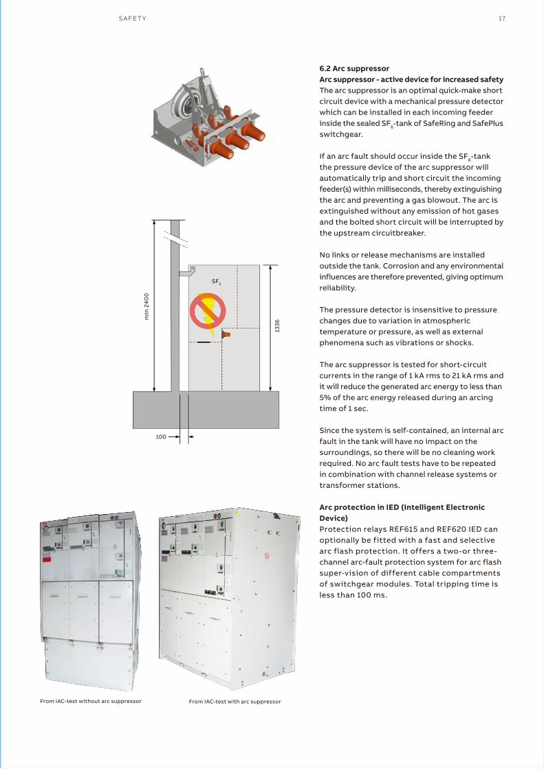
6.2 Arc suppressorArc suppressor - active device for increased safetyThe arc suppressor is an optimal quick-make short circuit device with a mechanical pressure detector which can be installed in each incoming feeder inside the sealed SF6-tank of SafeRing and SafePlus switchgear.
If an arc fault should occur inside the SF6-tank the pressure device of the arc suppressor will automatically trip and short circuit the incoming feeder(s) within milliseconds, thereby extinguishing the arc and preventing a gas blowout. The arc is extinguished without any emission of hot gases and the bolted short circuit will be interrupted by the upstream circuitbreaker.
No links or release mechanisms are installed outside the tank. Corrosion and any environmental influences are therefore prevented, giving optimum reliability.
The pressure detector is insensitive to pressure changes due to variation in atmospheric temperature or pressure, as well as external phenomena such as vibrations or shocks.
The arc suppressor is tested for short-circuit currents in the range of 1 kA rms to 21 kA rms and it will reduce the generated arc energy to less than 5% of the arc energy released during an arcing time of 1 sec.
Since the system is self-contained, an internal arc fault in the tank will have no impact on the surroundings, so there will be no cleaning work required. No arc fault tests have to be repeated in combination with channel release systems ortransformer stations.
Arc protection in IED (Intelligent Electronic Device)Protection relays REF615 and REF620 IED can optionally be fitted with a fast and selective arc flash protection. It offers a two-or three- channel arc-fault protection system for arc flash super-vision of different cable compartments of switchgear modules. Total tripping time is less than 100 ms.
SF6
min
24
00
1336
100
From IAC-test without arc suppressor From IAC-test with arc suppressor
18 G A S - I N S U L A T E D R I N G M A I N U N I T A N D G A S - I N S U L A T E D C O M P A C T S W I T C H G E A R P R O D U C T C A T A L O G U E
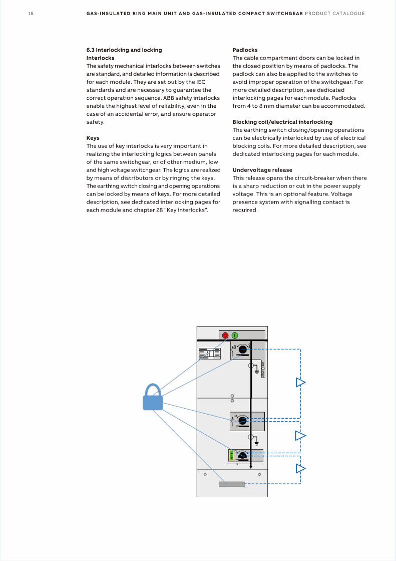
6.3 Interlocking and lockingInterlocksThe safety mechanical interlocks between switches are standard, and detailed information is described for each module. They are set out by the IEC standards and are necessary to guarantee the correct operation sequence. ABB safety interlocks enable the highest level of reliability, even in the case of an accidental error, and ensure operator safety.
KeysThe use of key interlocks is very important in realizing the interlocking logics between panels of the same switchgear, or of other medium, low and high voltage switchgear. The logics are realized by means of distributors or by ringing the keys. The earthing switch closing and opening operations can be locked by means of keys. For more detailed description, see dedicated interlocking pages for each module and chapter 28 “Key interlocks”.
PadlocksThe cable compartment doors can be locked in the closed position by means of padlocks. The padlock can also be applied to the switches to avoid improper operation of the switchgear. For more detailed description, see dedicated interlocking pages for each module. Padlocks from 4 to 8 mm diameter can be accommodated.
Blocking coil/electrical interlocking The earthing switch closing/opening operations can be electrically interlocked by use of electrical blocking coils. For more detailed description, see dedicated interlocking pages for each module.
Undervoltage releaseThis release opens the circuit-breaker when there is a sharp reduction or cut in the power supply voltage. This is an optional feature. Voltage presence system with signalling contact is required.
A P P L I C A T I O N S S A F E R I N G / S A F E P L U S 19
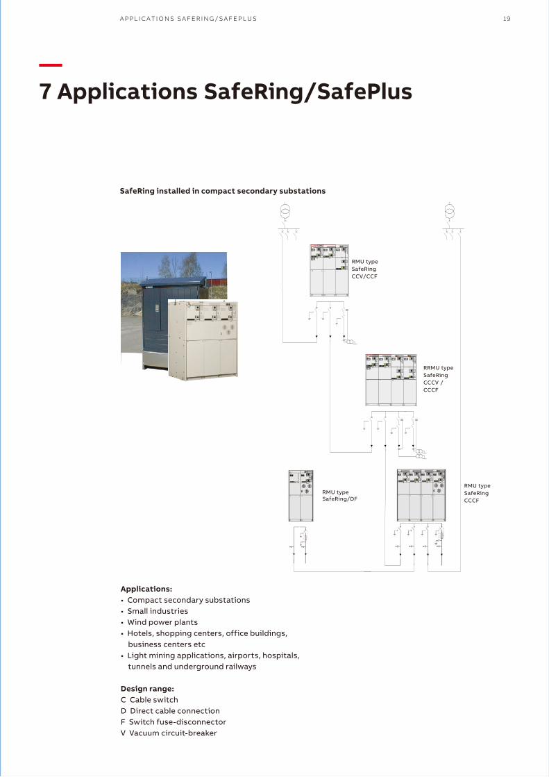
—7 Applications SafeRing/SafePlus
Applications:• Compact secondary substations• Small industries• Wind power plants• Hotels, shopping centers, office buildings,
business centers etc• Light mining applications, airports, hospitals,
tunnels and underground railways
Design range:C Cable switchD Direct cable connection F Switch fuse-disconnectorV Vacuum circuit-breaker
��� SafeRing
��� SafeRing
RMU typeSafeRingCCV/CCF
RRMU typeSafeRingCCCV /CCCF
RMU typeSafeRingCCCF
RMU type SafeRing/DF
SafeRing installed in compact secondary substations
20 G A S - I N S U L A T E D R I N G M A I N U N I T A N D G A S - I N S U L A T E D C O M P A C T S W I T C H G E A R P R O D U C T C A T A L O G U E
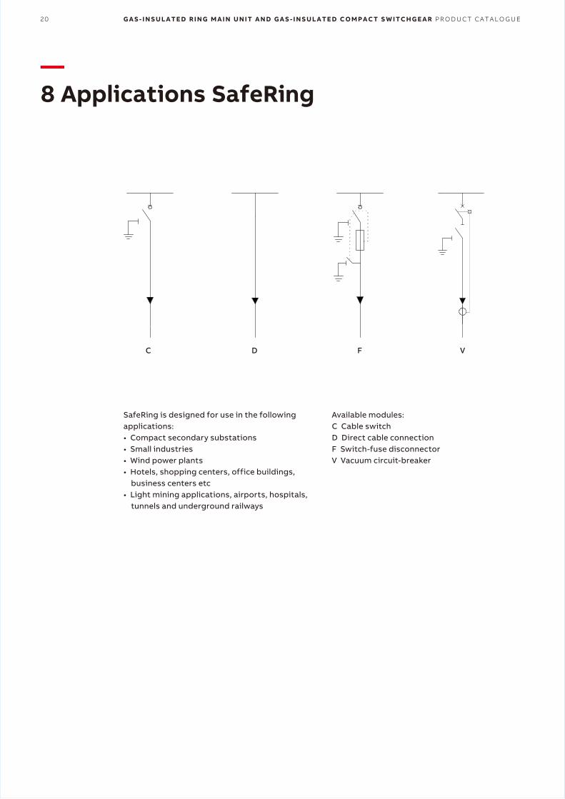
—8 Applications SafeRing
SafeRing is designed for use in the following applications:• Compact secondary substations• Small industries• Wind power plants• Hotels, shopping centers, office buildings,
business centers etc• Light mining applications, airports, hospitals,
tunnels and underground railways
C D F V
Available modules:C Cable switchD Direct cable connectionF Switch-fuse disconnectorV Vacuum circuit-breaker
A P P L I C A T I O N S S A F E R I N G 21
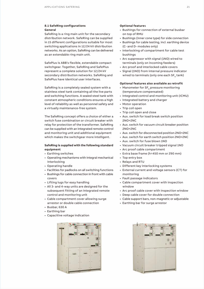
8.1 SafeRing configurationsGeneralSafeRing is a ring main unit for the secondary distribution network. SafeRing can be supplied in 15 different configurations suitable for most switching applications in 12/24 kV distributionnetworks. As an option, SafeRing can be delivered as an extendable ring main unit.
SafePlus is ABB’s flexible, extendable compact switchgear. Together, SafeRing and SafePlus represent a complete solution for 12/24 kV secondary distribution networks. SafeRing and SafePlus have identical user interfaces.
SafeRing is a completely sealed system with a stainless steel tank containing all the live parts and switching functions. A sealed steel tank with constant atmospheric conditions ensures a high level of reliability as well as personnel safety and a virtually maintenance-free system.
The SafeRing concept offers a choice of either a switch fuse combination or circuit breaker with relay for protection of the transformer. SafeRing can be supplied with an integrated remote control and monitoring unit and additional equipment which makes the switchgear more intelligent.
SafeRing is supplied with the following standard equipment• Earthing switches• Operating mechanisms with integral mechanical
interlocking• Operating handle• Facilities for padlocks on all switching functions• Bushings for cable connection in front with cable
covers• Lifting lugs for easy handling• All 3- and 4-way units are designed for the
subsequent fitting of an integrated remote control and monitoring unit
• Cable compartment cover allowing surge arrestor or double cable connection
• Busbar, 630 A• Earthing bar• Capacitive voltage indication
Optional features• Bushings for connection of external busbar
on top of RMU• Bushings (inner cone type) for side connection • Bushings for cable testing, incl. earthing device
(C- and D- modules only)• Interlocking of compartment for cable test
bushings• Arc suppressor with signal (1NO) wired to
terminals (only on incoming feeders)• Arc proof and interlocked cable covers• Signal (1NO) from internal pressure indicator
wired to terminals (only one each SF6 tank)
Optional features also available as retrofit• Manometer for SF6 pressure monitoring
(temperature compensated)• Integrated control and monitoring unit (ICMU)• Integrated battery and charger• Motor operation• Trip coil open• Trip coil open and close• Aux. switch for load break switch position
2NO+2NC• Aux. switch for vacuum circuit breaker position
2NO+2NC• Aux. switch for disconnected position 2NO+2NC• Aux. switch for earth switch position 2NO+2NC• Aux. switch for fuse blown 1NO• Vacuum circuit breaker tripped signal 1NO• Arc proof cable compartment• Extra base frame (h=450 mm or 290 mm)• Top entry box• Relays and RTU• Different key interlocking systems• External current and voltage sensors (CT) for
monitoring• Fault passage indicators• Cable compartment cover with inspection
window• Arc proof cable cover with inspection window• Deep cable cover for double connection• Cable support bars, non-magnetic or adjustable• Earthing bar for surge arrestor
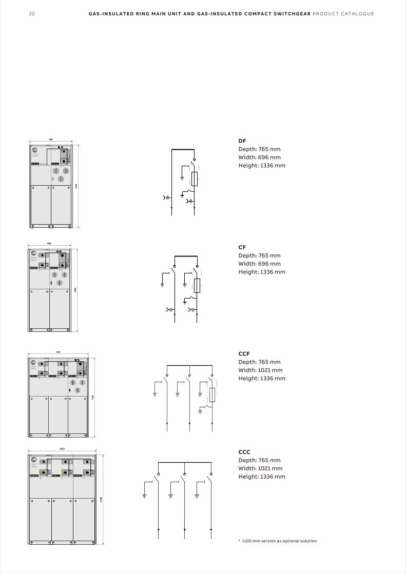
22 G A S - I N S U L A T E D R I N G M A I N U N I T A N D G A S - I N S U L A T E D C O M P A C T S W I T C H G E A R P R O D U C T C A T A L O G U E
* 1100 mm version as optional solution
DFDepth: 765 mmWidth: 696 mmHeight: 1336 mm
CFDepth: 765 mmWidth: 696 mmHeight: 1336 mm
CCFDepth: 765 mmWidth: 1021 mmHeight: 1336 mm
CCCDepth: 765 mmWidth: 1021 mmHeight: 1336 mm
SafeRing/SafePlus SF6 insulated
CSG / RMU SafeRing configurations 3.2
SafeRing
SafeRing
SafeRing
DeF
Depth: 765 mmWidth: 696 mmHeight: 1336 mm
CCF
Depth: 765 mmWidth: 1021 mmHeight: 1336 mm
CCCF
Depth: 765 mmWidth: 1346 mmHeight: 1336 mm
CCFF
SafeRing
696
1336
SAFERING
SafeRing IRMU IEC 298
ABB Kraft AS Made in Skien Norway
Weight / Gewicht : kgTemperature class: - 25 C inndoor/innenraum
Type : Serial no :IEC 129 IEC 420, 129U
Uw
I
n
Ima
Ith
kV
kV
A
kA
kA
kV
kV
A
kA
U
Uw
I
n
Ima
SAFERING
SafeRing IRMU IEC 298
ABB Kraft AS Made in Skien Norway
Weight / Gewicht : kgTemperature class: - 25 C inndoor/innenraum
Type : Serial no :IEC 265, 129 IEC 420, 129U
Uw
I
n
Ima
Ith
kV
kV
A
kA
kA
kV
kV
A
kA
U
Uw
I
n
Ima
696
1336
SafeRing/SafePlus SF6 insulated
CSG / RMU
12 ABB
SafeRing configurations 3.2
SafeRing
SafeRing
SafeRing
DeV
Depth: 765 mmWidth: 696 mmHeight: 1336 mm
CCV
Depth: 765 mmWidth: 1021 mmHeight: 1336 mm
CCCV
Depth: 765 mmWidth: 1346 mmHeight: 1336 mm
CCVV
Depth: 765 mmWidth: 1346 mmHeight: 1336 mm
SafeRing
SafeRing
CCC
Depth: 765 mmWidth: 1021 mmHeight: 1336 mm
SAFERING
SafeRing IRMU IEC 298
ABB Kraft AS Made in Skien Norway
Weight / Gewicht : kgTemperature class: - 25 C inndoor/innenraum
Type : Serial no :IEC 265, 129 IEC 420, 129U
Uw
I
n
Ima
Ith
kV
kV
A
kA
kA
kV
kV
A
kA
U
Uw
I
n
Ima
1021
1336
SAFERING
SafeRing IRMU IEC 298
ABB Kraft AS Made in Skien Norway
Weight / Gewicht : kgTemperature class: - 25 C inndoor/innenraum
Type : Serial no :IEC 265, 129U
Uw
I
n
Ima
Ith
kV
kV
A
kA
kA
1021
1336
A P P L I C A T I O N S S A F E R I N G 23
* 1100 mm version as optional solution
1021
1336
SAFERING
SafeRing IRMU IEC 298
ABB Kraft AS Made in Skien Norway
Weight / Gewicht : kgTemperature class: - 25 C inndoor/innenraum
Type : Serial no :IEC 265, 129 IEC 420, 129U
Uw
I
n
Ima
Ith
kV
kV
A
kA
kA
kV
kV
A
kA
U
Uw
I
n
Ima
1021
1336
SAFERING
SafeRing IRMU IEC 298
ABB Kraft AS Made in Skien Norway
Weight / Gewicht : kgTemperature class: - 25 C inndoor/innenraum
Type : Serial no :IEC 265, 129 IEC 420, 129U
Uw
I
n
Ima
Ith
kV
kV
A
kA
kA
kV
kV
A
kA
U
Uw
I
n
Ima
SafeRing/SafePlus SF6 insulated
CSG / RMU SafeRing configurations 3.2
SafeRing
SafeRing
SafeRing
DeF
Depth: 765 mmWidth: 696 mmHeight: 1336 mm
CCF
Depth: 765 mmWidth: 1021 mmHeight: 1336 mm
CCCF
Depth: 765 mmWidth: 1346 mmHeight: 1336 mm
CCFF
Depth: 765 mmWidth: 1346 mmHeight: 1336 mm
SafeRing
1346
1336
SAFERING
SafeRing IRMU IEC 298
ABB Kraft AS Made in Skien Norway
Weight / Gewicht : kgTemperature class: - 25 C inndoor/innenraum
Type : Serial no :IEC 265, 129 IEC 420, 129U
Uw
I
n
Ima
Ith
kV
kV
A
kA
kA
kV
kV
A
kA
U
Uw
I
n
Ima
1346
1336
SAFERING
SafeRing IRMU IEC 298
ABB Kraft AS Made in Skien Norway
Weight / Gewicht : kgTemperature class: - 25 C inndoor/innenraum
Type : Serial no :IEC 265, 129 IEC 420, 129U
Uw
I
n
Ima
Ith
kV
kV
A
kA
kA
kV
kV
A
kA
U
Uw
I
n
Ima
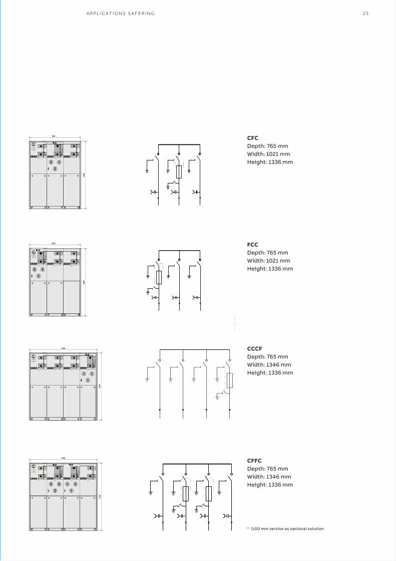
CFCDepth: 765 mmWidth: 1021 mmHeight: 1336 mm
FCCDepth: 765 mmWidth: 1021 mmHeight: 1336 mm
CCCFDepth: 765 mmWidth: 1346 mmHeight: 1336 mm
CFFCDepth: 765 mmWidth: 1346 mmHeight: 1336 mm
24 G A S - I N S U L A T E D R I N G M A I N U N I T A N D G A S - I N S U L A T E D C O M P A C T S W I T C H G E A R P R O D U C T C A T A L O G U E
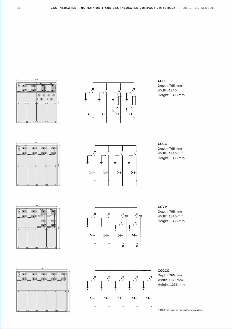
* 1100 mm version as optional solution
CCFFDepth: 765 mmWidth: 1346 mmHeight: 1336 mm
CCCCDepth: 765 mmWidth: 1346 mmHeight: 1336 mm
CCVVDepth: 765 mmWidth: 1346 mmHeight: 1336 mm
CCCCCDepth: 765 mmWidth: 1671 mmHeight: 1336 mm
1346
1336
SAFERING
SafeRing IRMU IEC 298
ABB Kraft AS Made in Skien Norway
Weight / Gewicht : kgTemperature class: - 25 C inndoor/innenraum
Type : Serial no :IEC 265, 129U
Uw
I
n
Ima
Ith
kV
kV
A
kA
kA
1346
1336
SAFERING
SafeRing IRMU IEC 298
ABB Kraft AS Made in Skien Norway
Weight / Gewicht : kgTemperature class: - 25 C inndoor/innenraum
Type : Serial no :IEC 265, 129 IEC 56U
Uw
I
n
Ima
Ith
kV
kV
A
kA
kA
kV
kV
A
kA
U
Uw
I
n
Ima
SCANDINAVIANELECRIC NORWAY
Serial no:
TYPE : MPRB-96-1.25
CE
CIRCUTORRESET
POWER
SCANDINAVIANELECRIC NORWAY
Serial no:
TYPE : MPRB-96-1.25
CE
CIRCUTORRESET
POWER
1671
1336
SAFERING
SafeRing IRMU IEC 298
ABB Kraft AS Made in Skien Norway
Weight / Gewicht : kgTemperature class: - 25 C inndoor/innenraum
Type : Serial no :IEC 265, 129U
Uw
I
n
Ima
Ith
kV
kV
A
kA
kA
1346
1336
SAFERING
SafeRing IRMU IEC 298
ABB Kraft AS Made in Skien Norway
Weight / Gewicht : kgTemperature class: - 25 C inndoor/innenraum
Type : Serial no :IEC 265, 129 IEC 420, 129U
Uw
I
n
Ima
Ith
kV
kV
A
kA
kA
kV
kV
A
kA
U
Uw
I
n
Ima
A P P L I C A T I O N S S A F E R I N G 25
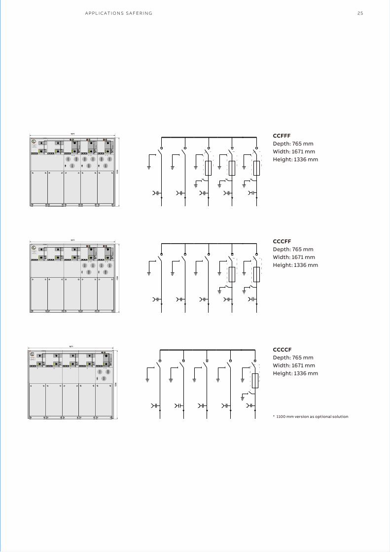
* 1100 mm version as optional solution
CCFFFDepth: 765 mmWidth: 1671 mmHeight: 1336 mm
CCCFFDepth: 765 mmWidth: 1671 mmHeight: 1336 mm
CCCCFDepth: 765 mmWidth: 1671 mmHeight: 1336 mm
1671
SAFERING
SafeRing IRMU IEC 298
ABB Kraft AS Made in Skien Norway
Weight / Gewicht : kgTemperature class: - 25 C inndoor/innenraum
Type : Serial no :IEC 265, 129 IEC 420, 129U
Uw
I
n
Ima
Ith
kV
kV
A
kA
kA
kV
kV
A
kA
U
Uw
I
n
Ima
1336
1671
SAFERING
SafeRing IRMU IEC 298
ABB Kraft AS Made in Skien Norway
Weight / Gewicht : kgTemperature class: - 25 C inndoor/innenraum
Type : Serial no :IEC 265, 129 IEC 420, 129U
Uw
I
n
Ima
Ith
kV
kV
A
kA
kA
kV
kV
A
kA
U
Uw
I
n
Ima
1336
1671
SAFERING
SafeRing IRMU IEC 298
ABB Kraft AS Made in Skien Norway
Weight / Gewicht : kgTemperature class: - 25 C inndoor/innenraum
Type : Serial no :IEC 265, 129 IEC 420, 129U
Uw
I
n
Ima
Ith
kV
kV
A
kA
kA
kV
kV
A
kA
U
Uw
I
n
Ima
1336
26 G A S - I N S U L A T E D R I N G M A I N U N I T A N D G A S - I N S U L A T E D C O M P A C T S W I T C H G E A R P R O D U C T C A T A L O G U E
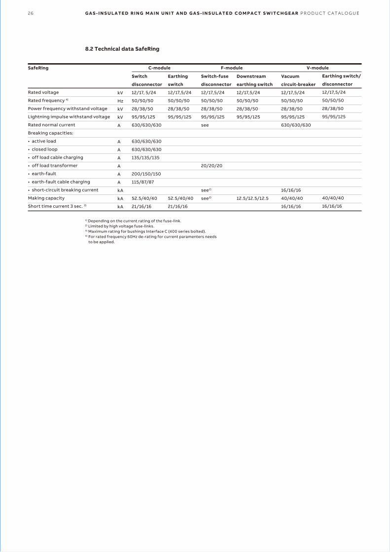
8.2 Technical data SafeRing
1) Depending on the current rating of the fuse-link.2) Limited by high voltage fuse-links.3) Maximum rating for bushings Interface C (400 series bolted).4) For rated frequency 60Hz de-rating for current paramenters needs
to be applied.
SafeRing
Rated voltage
Rated frequency 4)
Power frequency withstand voltage
Lightning impulse withstand voltage
Rated normal current
Breaking capacities:
• active load
• closed loop
• off load cable charging
• off load transformer
• earth-fault
• earth-fault cable charging
• short-circuit breaking current
Making capacity
Short time current 3 sec. 3)
Switch
disconnector
12/17, 5/24
50/50/50
28/38/50
95/95/125
630/630/630
630/630/630
630/630/630
135/135/135
200/150/150
115/87/87
52.5/40/40
21/16/16
Earthing
switch
12/17,5/24
50/50/50
28/38/50
95/95/125
52.5/40/40
21/16/16
Switch-fuse
disconnector
12/17,5/24
50/50/50
28/38/50
95/95/125
see
20/20/20
see2)
see2)
Downstream
earthing switch
12/17,5/24
50/50/50
28/38/50
95/95/125
12.5/12.5/12.5
Vacuum
circuit-breaker
12/17,5/24
50/50/50
28/38/50
95/95/125
630/630/630
16/16/16
40/40/40
16/16/16
Earthing switch/
disconnector
12/17,5/24
50/50/50
28/38/50
95/95/125
40/40/40
16/16/16
C-module F-module V-module
kV
Hz
kV
kV
A
A
A
A
A
A
A
kA
kA
kA
S A F E P L U S M O D U L E S 27
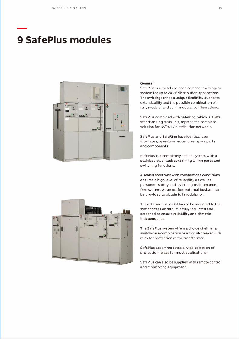
—9 SafePlus modules
GeneralSafePlus is a metal enclosed compact switchgear system for up to 24 kV distribution applications. The switchgear has a unique flexibility due to its extendability and the possible combination of fully modular and semi-modular configurations.
SafePlus combined with SafeRing, which is ABB’s standard ring main unit, represent a complete solution for 12/24 kV distribution networks.
SafePlus and SafeRing have identical user interfaces, operation procedures, spare parts and components.
SafePlus is a completely sealed system with a stainless steel tank containing all live parts and switching functions.
A sealed steel tank with constant gas conditions ensures a high level of reliability as well as personnel safety and a virtually maintenance- free system. As an option, external busbars can be provided to obtain full modularity.
The external busbar kit has to be mounted to the switchgears on site. It is fully insulated and screened to ensure reliability and climatic independence.
The SafePlus system offers a choice of either a switch-fuse combination or a circuit-breaker with relay for protection of the transformer.
SafePlus accommodates a wide selection of protection relays for most applications.
SafePlus can also be supplied with remote control and monitoring equipment.
28 G A S - I N S U L A T E D R I N G M A I N U N I T A N D G A S - I N S U L A T E D C O M P A C T S W I T C H G E A R P R O D U C T C A T A L O G U E
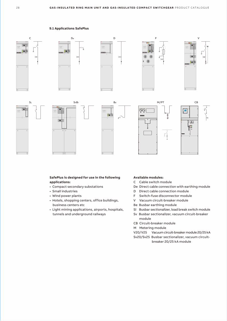
9.1 Applications SafePlus
SafePlus is designed for use in the following applications:• Compact secondary substations• Small industries• Wind power plants• Hotels, shopping centers, office buildings,
business centers etc• Light mining applications, airports, hospitals,
tunnels and underground railways
C
SL SVBr Be M/PT CB
De D F VSAFEPLUS
SafePlus IRMU IEC 298
ABB Made in China
Weight / Gewicht : kg
Temperature class: - 25 C inndoor/innenraum
Type : Serial no :
IEC 129 IEC 420, 129U
Uw
I
n
Ima
Ith
kV
kV
A
kA
kA
kV
kV
A
kA
U
Uw
I
n
Ima
SAFEPLUS
SafePlus IRMU IEC 298
ABB Made in China
Weight / Gewicht : kg
Temperature class: - 25 C inndoor/innenraum
Type : Serial no :
IEC 129 IEC 420, 129U
Uw
I
n
Ima
Ith
kV
kV
A
kA
kA
kV
kV
A
kA
U
Uw
I
n
Ima
SAFEPLUS
SafePlus IRMU IEC 298
ABB Made in China
Weight / Gewicht : kg
Temperature class: - 25 C inndoor/innenraum
Type : Serial no :
IEC 129 IEC 420, 129U
Uw
I
n
Ima
Ith
kV
kV
A
kA
kA
kV
kV
A
kA
U
Uw
I
n
Ima
SAFEPLUS
SafePlus IRMU IEC 298
ABB Made in China
Weight / Gewicht : kg
Temperature class: - 25 C inndoor/innenraum
Type : Serial no :
IEC 129 IEC 420, 129U
Uw
I
n
Ima
Ith
kV
kV
A
kA
kA
kV
kV
A
kA
U
Uw
I
n
Ima
SAFEPLUS
SafePlus IRMU IEC 298
ABB Made in China
Weight / Gewicht : kg
Temperature class: - 25 C inndoor/innenraum
Type : Serial no :
IEC 129 IEC 420, 129U
Uw
I
n
Ima
Ith
kV
kV
A
kA
kA
kV
kV
A
kA
U
Uw
I
n
Ima
SAFEPLUS
SafePlus IRMU IEC 298
ABB Made in China
Weight / Gewicht : kg
Temperature class: - 25 C inndoor/innenraum
Type : Serial no :
IEC 129 IEC 420, 129U
Uw
I
n
Ima
Ith
kV
kV
A
kA
kA
kV
kV
A
kA
U
Uw
I
n
Ima
SafePlus IRMU IEC 298
ABB Made in China
Weight / Gewicht : kg
Temperature class: - 25 C inndoor/innenraum
Type : Serial no :
IEC 129 IEC 420, 129U
Uw
I
n
Ima
Ith
kV
kV
A
kA
kA
kV
kV
A
kA
U
Uw
I
n
Ima
SAFEPLUS SAFEPLUS
SafePlus IRMU IEC 298
ABB Made in China
Weight / Gewicht : kg
Temperature class: - 25 C inndoor/innenraum
Type : Serial no :
IEC 129 IEC 420, 129U
Uw
I
n
Ima
Ith
kV
kV
A
kA
kA
kV
kV
A
kA
U
Uw
I
n
Ima
Available modules:C Cable switch moduleDe Direct cable connection with earthing moduleD Direct cable connection moduleF Switch-fuse disconnector moduleV Vacuum circuit-breaker moduleBe Busbar earthing moduleSl Busbar sectionalizer, load break switch moduleSv Busbar sectionalizer, vacuum circuit-breaker
moduleCB Circuit-breaker moduleM Metering moduleV20/V25 Vacuum circuit-breaker module 20/25 kASv20/Sv25 Busbar sectionalizer, vacuum circuit-
breaker 20/25 kA module
S A F E P L U S M O D U L E S 29
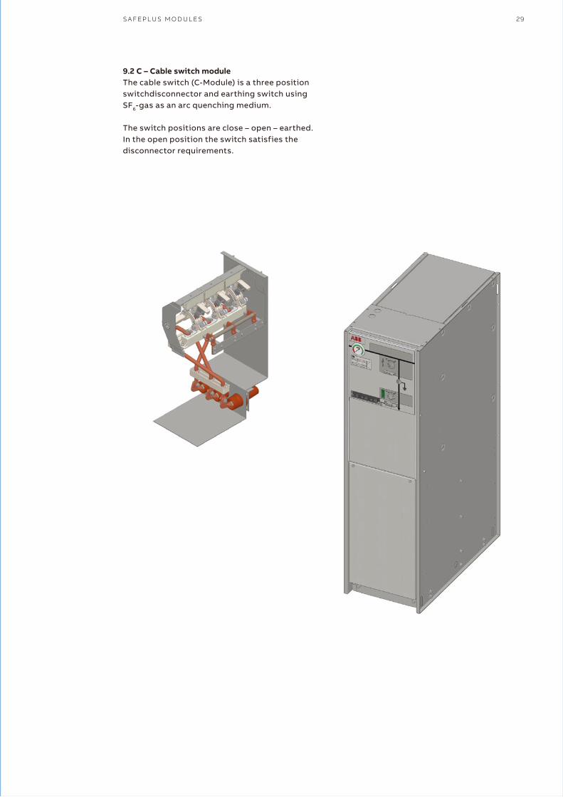
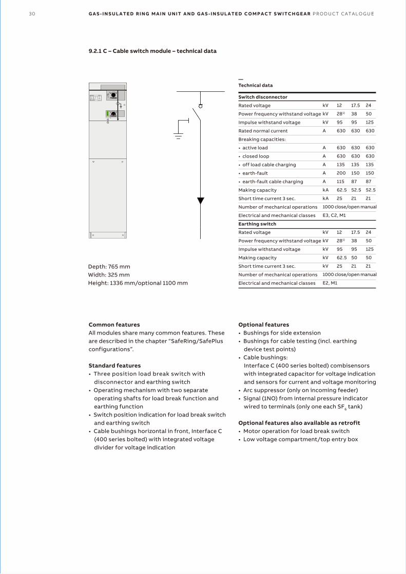
9.2 C – Cable switch moduleThe cable switch (C-Module) is a three position switchdisconnector and earthing switch using SF6-gas as an arc quenching medium.
The switch positions are close – open – earthed. In the open position the switch satisfies the disconnector requirements.
30 G A S - I N S U L A T E D R I N G M A I N U N I T A N D G A S - I N S U L A T E D C O M P A C T S W I T C H G E A R P R O D U C T C A T A L O G U E
9.2.1 C – Cable switch module – technical data
Depth: 765 mmWidth: 325 mmHeight: 1336 mm/optional 1100 mm
Common featuresAll modules share many common features. These are described in the chapter “SafeRing/SafePlus configurations”.
Standard features• Three position load break switch with
disconnector and earthing switch• Operating mechanism with two separate
operating shafts for load break function and earthing function
• Switch position indication for load break switch and earthing switch
• Cable bushings horizontal in front, Interface C (400 series bolted) with integrated voltage divider for voltage indication
Optional features• Bushings for side extension • Bushings for cable testing (incl. earthing
device test points)• Cable bushings:
Interface C (400 series bolted) combisensors with integrated capacitor for voltage indication and sensors for current and voltage monitoring
• Arc suppressor (only on incoming feeder)• Signal (1NO) from internal pressure indicator
wired to terminals (only one each SF6 tank)
Optional features also available as retrofit• Motor operation for load break switch• Low voltage compartment/top entry box
Switch disconnector
Rated voltage
Power frequency withstand voltage
Impulse withstand voltage
Rated normal current
Breaking capacities:
• active load
• closed loop
• off load cable charging
• earth-fault
• earth-fault cable charging
Making capacity
Short time current 3 sec.
Number of mechanical operations
Electrical and mechanical classes
Earthing switch
Rated voltage
Power frequency withstand voltage
Impulse withstand voltage
Making capacity
Short time current 3 sec.
Number of mechanical operations
Electrical and mechanical classes
kV
kV
kV
A
A
A
A
A
A
kA
kA
1000 close/open manual
E3, C2, M1
kV
kV
kV
kV
kV
1000 close/open manual
E2, M1
12
281)
95
630
630
630
135
200
115
62.5
25
12
281)
95
62.5
25
17.5
38
95
630
630
630
135
150
87
52.5
21
17.5
38
95
50
21
24
50
125
630
630
630
135
150
87
52.5
21
24
50
125
50
21
—Technical data
S A F E P L U S M O D U L E S 31
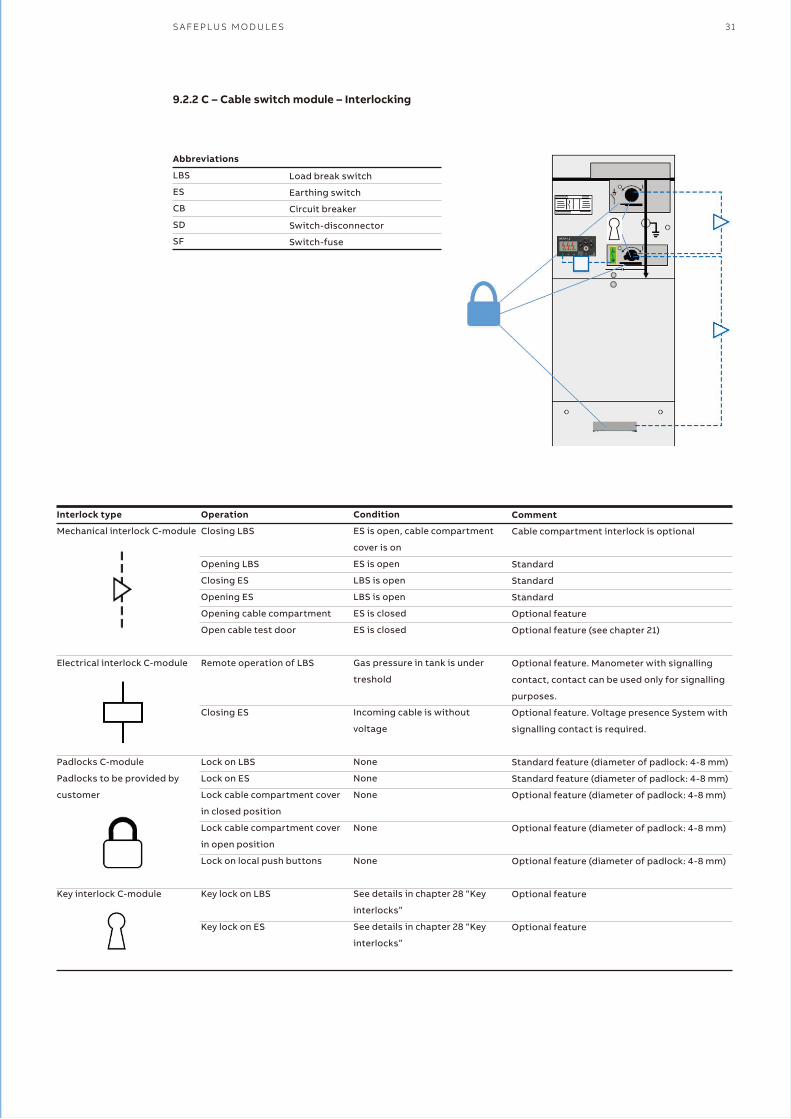
9.2.2 C – Cable switch module – Interlocking
Interlock type
Mechanical interlock C-module
Electrical interlock C-module
Padlocks C-module
Padlocks to be provided by
customer
Key interlock C-module
Operation
Closing LBS
Opening LBS
Closing ES
Opening ES
Opening cable compartment
Open cable test door
Remote operation of LBS
Closing ES
Lock on LBS
Lock on ES
Lock cable compartment cover
in closed position
Lock cable compartment cover
in open position
Lock on local push buttons
Key lock on LBS
Key lock on ES
Condition
ES is open, cable compartment
cover is on
ES is open
LBS is open
LBS is open
ES is closed
ES is closed
Gas pressure in tank is under
treshold
Incoming cable is without
voltage
None
None
None
None
None
See details in chapter 28 “Key
interlocks”
See details in chapter 28 “Key
interlocks”
Comment
Cable compartment interlock is optional
Standard
Standard
Standard
Optional feature
Optional feature (see chapter 21)
Optional feature. Manometer with signalling
contact, contact can be used only for signalling
purposes.
Optional feature. Voltage presence System with
signalling contact is required.
Standard feature (diameter of padlock: 4-8 mm)
Standard feature (diameter of padlock: 4-8 mm)
Optional feature (diameter of padlock: 4-8 mm)
Optional feature (diameter of padlock: 4-8 mm)
Optional feature (diameter of padlock: 4-8 mm)
Optional feature
Optional feature
Abbreviations
LBS
ES
CB
SD
SF
Load break switch
Earthing switch
Circuit breaker
Switch-disconnector
Switch-fuse
32 G A S - I N S U L A T E D R I N G M A I N U N I T A N D G A S - I N S U L A T E D C O M P A C T S W I T C H G E A R P R O D U C T C A T A L O G U E
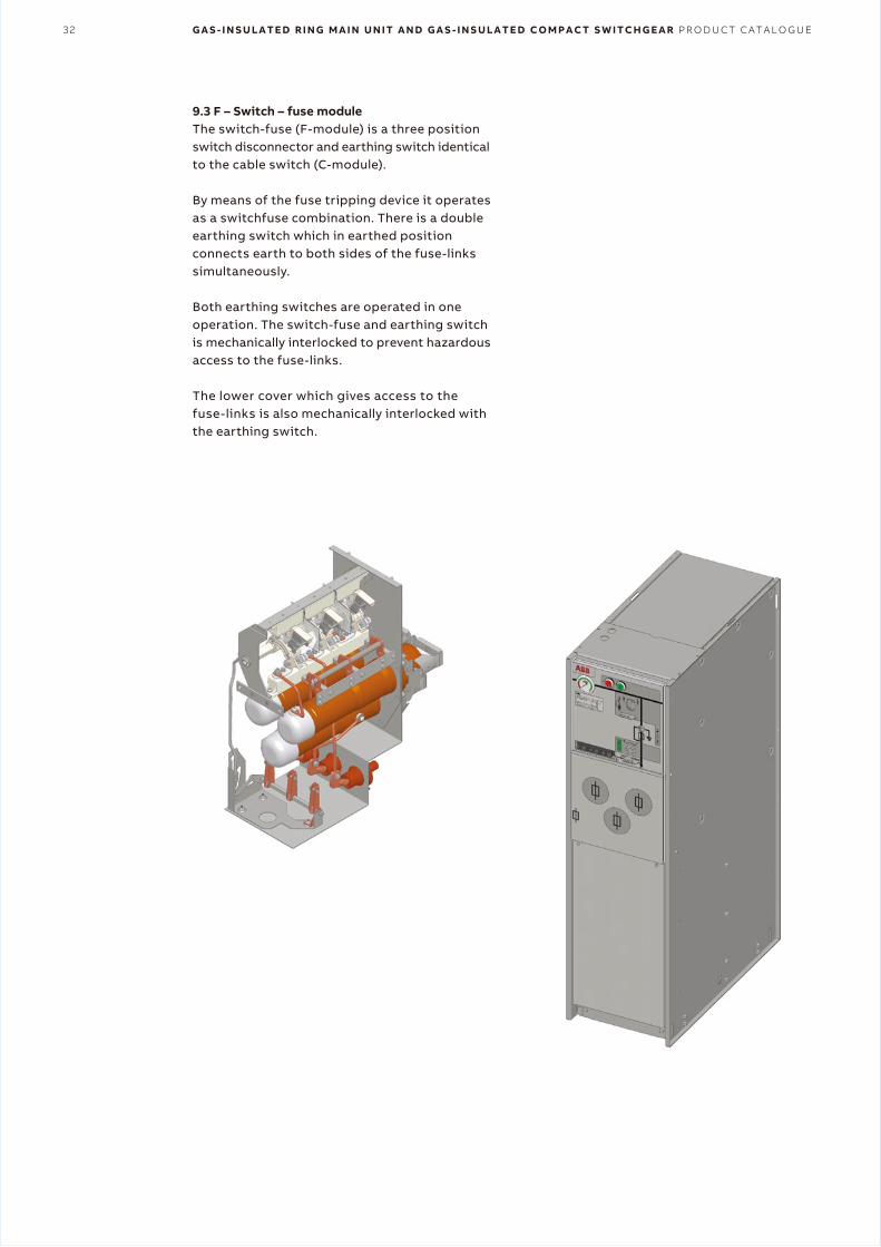
9.3 F – Switch – fuse moduleThe switch-fuse (F-module) is a three position switch disconnector and earthing switch identical to the cable switch (C-module).
By means of the fuse tripping device it operates as a switchfuse combination. There is a double earthing switch which in earthed position connects earth to both sides of the fuse-linkssimultaneously.
Both earthing switches are operated in one operation. The switch-fuse and earthing switch is mechanically interlocked to prevent hazardous access to the fuse-links.
The lower cover which gives access to the fuse-links is also mechanically interlocked with the earthing switch.
S A F E P L U S M O D U L E S 33
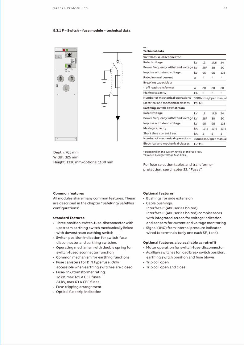
9.3.1 F – Switch – fuse module – technical data
Depth: 765 mmWidth: 325 mmHeight: 1336 mm/optional 1100 mm
1) Depening on the current rating of the fuse-link.2) Limited by high voltage fuse-links.
For fuse selection tables and transformer protection, see chapter 22, “Fuses”.
Common featuresAll modules share many common features. These are described in the chapter “SafeRing/SafePlus configurations”.
Standard features• Three position switch-fuse-disconnector with
upstream earthing switch mechanically linked with downstream earthing switch
• Switch position indication for switch-fuse- disconnector and earthing switches
• Operating mechanism with double spring for switch-fusedisconnector function
• Common mechanism for earthing functions• Fuse canisters for DIN type fuse. Only
accessible when earthing switches are closed• Fuse-link/transformer rating:
12 kV, max 125 A CEF fuses24 kV, max 63 A CEF fuses
• Fuse tripping arrangement• Optical fuse trip indication
Switch-fuse-disconnector
Rated voltage
Power frequency withstand voltage
Impulse withstand voltage
Rated normal current
Breaking capacities:
• off load transformer
Making capacity
Number of mechanical operations
Electrical and mechanical classes
Earthing switch downstream
Rated voltage
Power frequency withstand voltage
Impulse withstand voltage
Making capacity
Short time current 1 sec.
Number of mechanical operations
Electrical and mechanical classes
kV
kV
kV
A
A
kA
1000 close/open manual
E3, M1
kV
kV
kV
kA
kA
1000 close/open manual
E2, M1
12
283)
951)
202)
12
282)
95
12.5
5
17.5
38
951)
202)
17.5
38
95
12.5
5
24
50
1251)
202)
24
50
125
12.5
5
Optional features• Bushings for side extension • Cable bushings:
Interface C (400 series bolted)Interface C (400 series bolted) combisensors with integrated screen for voltage indication and sensors for current and voltage monitoring
• Signal (1NO) from internal pressure indicator wired to terminals (only one each SF6 tank)
Optional features also available as retrofit• Motor operation for switch-fuse-disconnector• Auxiliary switches for load break switch position,
earthing switch position and fuse blown• Trip coil open• Trip coil open and close
—Technical data
34 G A S - I N S U L A T E D R I N G M A I N U N I T A N D G A S - I N S U L A T E D C O M P A C T S W I T C H G E A R P R O D U C T C A T A L O G U E
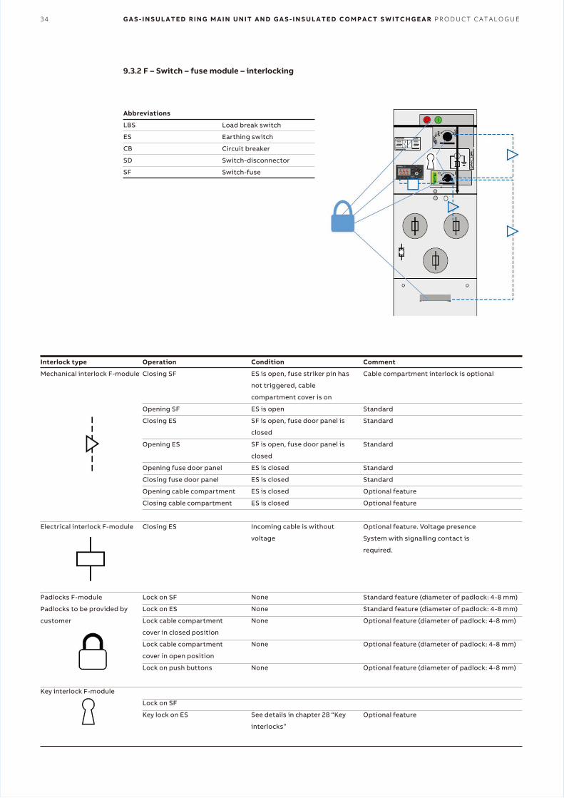
9.3.2 F – Switch – fuse module – interlocking
Interlock type
Mechanical interlock F-module
Electrical interlock F-module
Padlocks F-module
Padlocks to be provided by
customer
Key interlock F-module
Operation
Closing SF
Opening SF
Closing ES
Opening ES
Opening fuse door panel
Closing fuse door panel
Opening cable compartment
Closing cable compartment
Closing ES
Lock on SF
Lock on ES
Lock cable compartment
cover in closed position
Lock cable compartment
cover in open position
Lock on push buttons
Lock on SF
Key lock on ES
Condition
ES is open, fuse striker pin has
not triggered, cable
compartment cover is on
ES is open
SF is open, fuse door panel is
closed
SF is open, fuse door panel is
closed
ES is closed
ES is closed
ES is closed
ES is closed
Incoming cable is without
voltage
None
None
None
None
None
See details in chapter 28 “Key
interlocks”
Abbreviations
LBS
ES
CB
SD
SF
Load break switch
Earthing switch
Circuit breaker
Switch-disconnector
Switch-fuse
Comment
Cable compartment interlock is optional
Standard
Standard
Standard
Standard
Standard
Optional feature
Optional feature
Optional feature. Voltage presence
System with signalling contact is
required.
Standard feature (diameter of padlock: 4-8 mm)
Standard feature (diameter of padlock: 4-8 mm)
Optional feature (diameter of padlock: 4-8 mm)
Optional feature (diameter of padlock: 4-8 mm)
Optional feature (diameter of padlock: 4-8 mm)
Optional feature
S A F E P L U S M O D U L E S 35
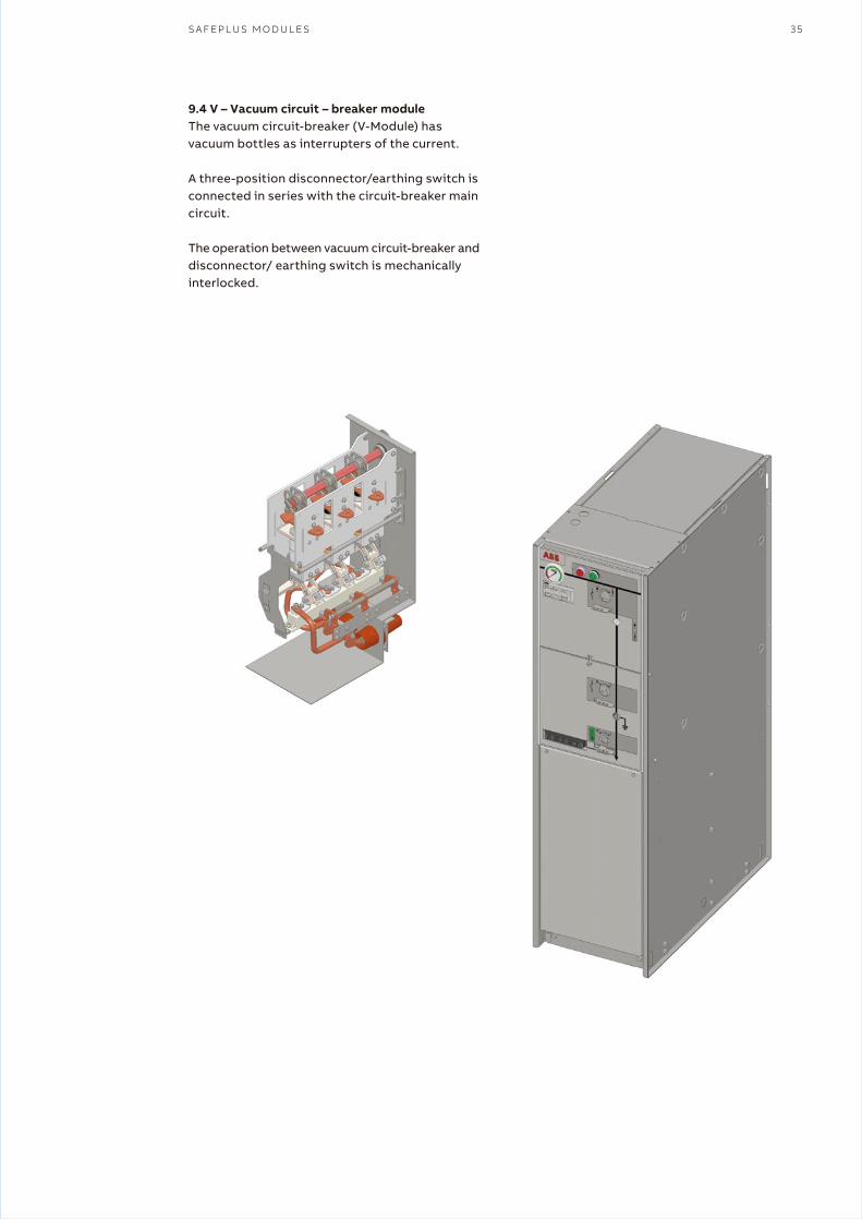
9.4 V – Vacuum circuit – breaker moduleThe vacuum circuit-breaker (V-Module) has vacuum bottles as interrupters of the current.
A three-position disconnector/earthing switch is connected in series with the circuit-breaker main circuit.
The operation between vacuum circuit-breaker and disconnector/ earthing switch is mechanically interlocked.
36 G A S - I N S U L A T E D R I N G M A I N U N I T A N D G A S - I N S U L A T E D C O M P A C T S W I T C H G E A R P R O D U C T C A T A L O G U E
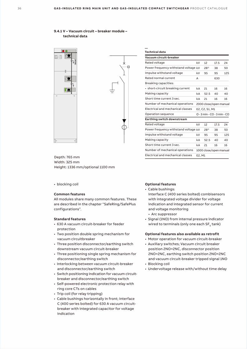
Depth: 765 mmWidth: 325 mmHeight: 1336 mm/optional 1100 mm
• blocking coil
Common featuresAll modules share many common features. These are described in the chapter “SafeRing/SafePlus configurations”.
Standard features• 630 A vacuum circuit-breaker for feeder
protection• Two position double spring mechanism for
vacuum circuitbreaker• Three position disconnector/earthing switch
downstream vacuum circuit-breaker• Three positioning single spring mechanism for
disconnector/earthing switch• Interlocking between vacuum circuit-breaker
and disconnector/earthing switch• Switch positioning indication for vacuum circuit-
breaker and disconnector/earthing switch• Self-powered electronic protection relay with
ring core CTs on cables• Trip coil (for relay tripping)• Cable bushings horizontally in front; Interface
C (400 series bolted) for 630 A vacuum circuit- breaker with integrated capacitor for voltage indication
Vacuum circuit-breaker
Rated voltage
Power frequency withstand voltage
Impulse withstand voltage
Rated normal current
Breaking capacities:
• short-circuit breaking current
Making capacity
Short time current 3 sec.
Number of mechanical operations
Electrical and mechanical classes
Operation sequence
Earthing switch downstream
Rated voltage
Power frequency withstand voltage
Impulse withstand voltage
Making capacity
Short time current 3 sec.
Number of mechanical operations
Electrical and mechanical classes
kV
kV
kV
A
kA
kA
kA
2000 close/open manual
E2, C2, S1, M1
O - 3 min - CO - 3 min - CO
kV
kV
kV
kA
kA
1000 close/open manual
E2, M1
12
281)
95
21
52.5
21
12
281)
95
52.5
21
17.5
38
95
630
16
40
16
17.5
38
95
40
16
24
50
125
16
40
16
24
50
125
40
16
Optional features• Cable bushings:
Interface C (400 series bolted) combisensors with integrated voltage divider for voltage indication and integrated sensor for current and voltage monitoring• Arc suppressor
• Signal (1NO) from internal pressure indicator wired to terminals (only one each SF6 tank)
Optional features also available as retrofit• Motor operation for vacuum circuit-breaker• Auxiliary switches; Vacuum circuit breaker
position 2NO+2NC, disconnector position 2NO+2NC, earthing switch position 2NO+2NC and vacuum circuit-breaker tripped signal 1NO
• Blocking coil• Undervoltage release with/without time delay
9.4.1 V – Vacuum circuit – breaker module – technical data
—Technical data
S A F E P L U S M O D U L E S 37
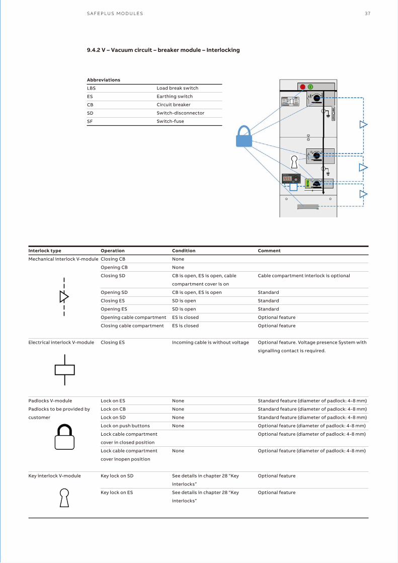
9.4.2 V – Vacuum circuit – breaker module – Interlocking
Interlock type
Mechanical interlock V-module
Electrical interlock V-module
Padlocks V-module
Padlocks to be provided by
customer
Key interlock V-module
Operation
Closing CB
Opening CB
Closing SD
Opening SD
Closing ES
Opening ES
Opening cable compartment
Closing cable compartment
Closing ES
Lock on ES
Lock on CB
Lock on SD
Lock on push buttons
Lock cable compartment
cover in closed position
Lock cable compartment
cover inopen position
Key lock on SD
Key lock on ES
Condition
None
None
CB is open, ES is open, cable
compartment cover is on
CB is open, ES is open
SD is open
SD is open
ES is closed
ES is closed
Incoming cable is without voltage
None
None
None
None
None
See details in chapter 28 “Key
interlocks”
See details in chapter 28 “Key
interlocks”
Comment
Cable compartment interlock is optional
Standard
Standard
Standard
Optional feature
Optional feature
Optional feature. Voltage presence System with
signalling contact is required.
Standard feature (diameter of padlock: 4-8 mm)
Standard feature (diameter of padlock: 4-8 mm)
Standard feature (diameter of padlock: 4-8 mm)
Optional feature (diameter of padlock: 4-8 mm)
Optional feature (diameter of padlock: 4-8 mm)
Optional feature (diameter of padlock: 4-8 mm)
Optional feature
Optional feature
Abbreviations
LBS
ES
CB
SD
SF
Load break switch
Earthing switch
Circuit breaker
Switch-disconnector
Switch-fuse
38 G A S - I N S U L A T E D R I N G M A I N U N I T A N D G A S - I N S U L A T E D C O M P A C T S W I T C H G E A R P R O D U C T C A T A L O G U E
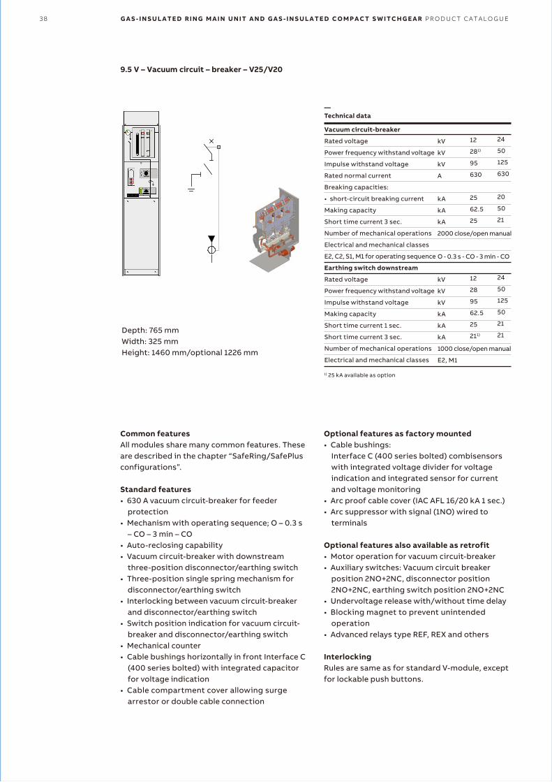
9.5 V – Vacuum circuit – breaker – V25/V20
Depth: 765 mmWidth: 325 mmHeight: 1460 mm/optional 1226 mm
1) 25 kA available as option
Common featuresAll modules share many common features. These are described in the chapter “SafeRing/SafePlus configurations”.
Standard features• 630 A vacuum circuit-breaker for feeder
protection• Mechanism with operating sequence; O – 0.3 s
– CO – 3 min – CO• Auto-reclosing capability• Vacuum circuit-breaker with downstream
three-position disconnector/earthing switch• Three-position single spring mechanism for
disconnector/earthing switch• Interlocking between vacuum circuit-breaker
and disconnector/earthing switch• Switch position indication for vacuum circuit-
breaker and disconnector/earthing switch• Mechanical counter• Cable bushings horizontally in front Interface C
(400 series bolted) with integrated capacitor for voltage indication
• Cable compartment cover allowing surge arrestor or double cable connection
Vacuum circuit-breaker
Rated voltage
Power frequency withstand voltage
Impulse withstand voltage
Rated normal current
Breaking capacities:
• short-circuit breaking current
Making capacity
Short time current 3 sec.
Number of mechanical operations
Electrical and mechanical classes
E2, C2, S1, M1 for operating sequence
Earthing switch downstream
Rated voltage
Power frequency withstand voltage
Impulse withstand voltage
Making capacity
Short time current 1 sec.
Short time current 3 sec.
Number of mechanical operations
Electrical and mechanical classes
kV
kV
kV
A
kA
kA
kA
2000 close/open manual
O - 0.3 s - CO - 3 min - CO
kV
kV
kV
kA
kA
kA
1000 close/open manual
E2, M1
12
281)
95
630
25
62.5
25
12
28
95
62.5
25
211)
24
50
125
630
20
50
21
24
50
125
50
21
21
Optional features as factory mounted• Cable bushings:
Interface C (400 series bolted) combisensors with integrated voltage divider for voltage indication and integrated sensor for current and voltage monitoring
• Arc proof cable cover (IAC AFL 16/20 kA 1 sec.)• Arc suppressor with signal (1NO) wired to
terminals
Optional features also available as retrofit• Motor operation for vacuum circuit-breaker• Auxiliary switches: Vacuum circuit breaker
position 2NO+2NC, disconnector position 2NO+2NC, earthing switch position 2NO+2NC
• Undervoltage release with/without time delay• Blocking magnet to prevent unintended
operation• Advanced relays type REF, REX and others
InterlockingRules are same as for standard V-module, except for lockable push buttons.
—Technical data
S A F E P L U S M O D U L E S 39
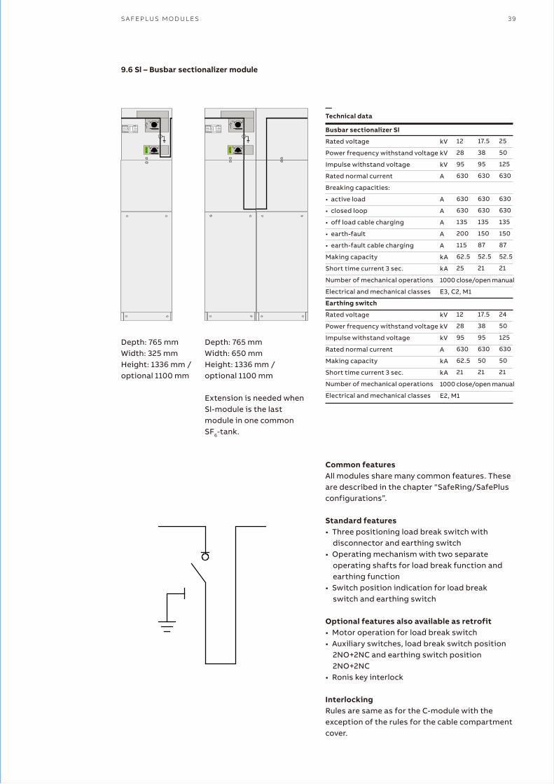
9.6 Sl – Busbar sectionalizer module
Depth: 765 mmWidth: 325 mmHeight: 1336 mm /optional 1100 mm
Busbar sectionalizer Sl
Rated voltage
Power frequency withstand voltage
Impulse withstand voltage
Rated normal current
Breaking capacities:
• active load
• closed loop
• off load cable charging
• earth-fault
• earth-fault cable charging
Making capacity
Short time current 3 sec.
Number of mechanical operations
Electrical and mechanical classes
Earthing switch
Rated voltage
Power frequency withstand voltage
Impulse withstand voltage
Rated normal current
Making capacity
Short time current 3 sec.
Number of mechanical operations
Electrical and mechanical classes
kV
kV
kV
A
A
A
A
A
A
kA
kA
1000 close/open manual
E3, C2, M1
kV
kV
kV
A
kA
kA
1000 close/open manual
E2, M1
12
28
95
630
630
630
135
200
115
62.5
25
12
28
95
630
62.5
21
17.5
38
95
630
630
630
135
150
87
52.5
21
17.5
38
95
630
50
21
25
50
125
630
630
630
135
150
87
52.5
21
24
50
125
630
50
21
Common featuresAll modules share many common features. These are described in the chapter “SafeRing/SafePlus configurations”.
Standard features• Three positioning load break switch with
disconnector and earthing switch• Operating mechanism with two separate
operating shafts for load break function and earthing function
• Switch position indication for load break switch and earthing switch
Optional features also available as retrofit• Motor operation for load break switch• Auxiliary switches, load break switch position
2NO+2NC and earthing switch position 2NO+2NC
• Ronis key interlock
Interlocking Rules are same as for the C-module with the exception of the rules for the cable compartment cover.
Depth: 765 mmWidth: 650 mmHeight: 1336 mm /optional 1100 mm
Extension is needed whenSl-module is the lastmodule in one common SF6-tank.
—Technical data
40 G A S - I N S U L A T E D R I N G M A I N U N I T A N D G A S - I N S U L A T E D C O M P A C T S W I T C H G E A R P R O D U C T C A T A L O G U E
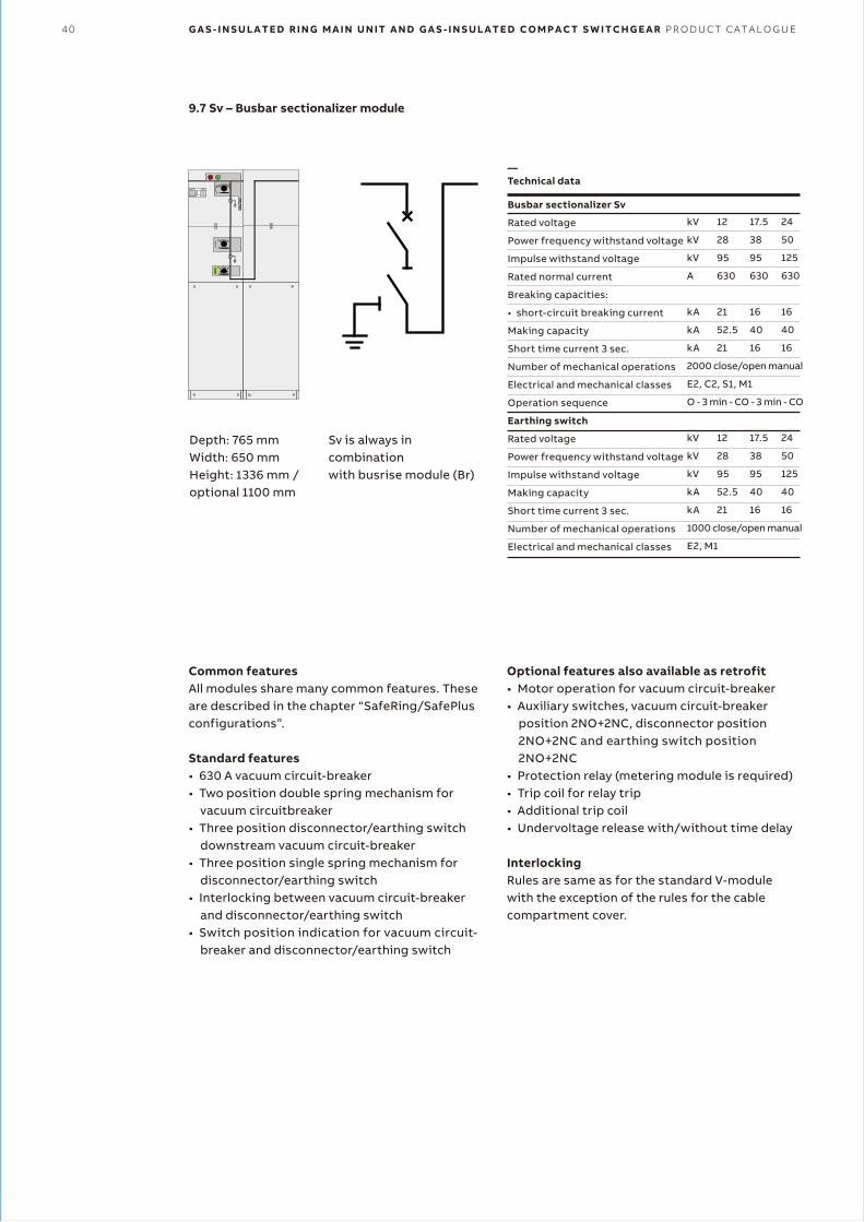
9.7 Sv – Busbar sectionalizer module
Depth: 765 mmWidth: 650 mmHeight: 1336 mm /optional 1100 mm
Common featuresAll modules share many common features. These are described in the chapter “SafeRing/SafePlus configurations”.
Standard features• 630 A vacuum circuit-breaker• Two position double spring mechanism for
vacuum circuitbreaker• Three position disconnector/earthing switch
downstream vacuum circuit-breaker• Three position single spring mechanism for
disconnector/earthing switch• Interlocking between vacuum circuit-breaker
and disconnector/earthing switch• Switch position indication for vacuum circuit-
breaker and disconnector/earthing switch
Busbar sectionalizer Sv
Rated voltage
Power frequency withstand voltage
Impulse withstand voltage
Rated normal current
Breaking capacities:
• short-circuit breaking current
Making capacity
Short time current 3 sec.
Number of mechanical operations
Electrical and mechanical classes
Operation sequence
Earthing switch
Rated voltage
Power frequency withstand voltage
Impulse withstand voltage
Making capacity
Short time current 3 sec.
Number of mechanical operations
Electrical and mechanical classes
kV
kV
kV
A
kA
kA
kA
2000 close/open manual
E2, C2, S1, M1
O - 3 min - CO - 3 min - CO
kV
kV
kV
kA
kA
1000 close/open manual
E2, M1
12
28
95
630
21
52.5
21
12
28
95
52.5
21
17.5
38
95
630
16
40
16
17.5
38
95
40
16
24
50
125
630
16
40
16
24
50
125
40
16
Sv is always in combinationwith busrise module (Br)
Optional features also available as retrofit• Motor operation for vacuum circuit-breaker• Auxiliary switches, vacuum circuit-breaker
position 2NO+2NC, disconnector position 2NO+2NC and earthing switch position 2NO+2NC
• Protection relay (metering module is required)• Trip coil for relay trip• Additional trip coil• Undervoltage release with/without time delay
InterlockingRules are same as for the standard V-module with the exception of the rules for the cable compartment cover.
—Technical data
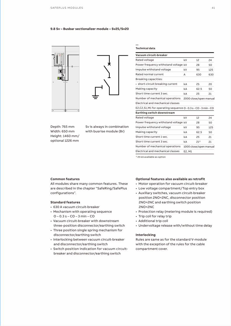
S A F E P L U S M O D U L E S 41
9.8 Sv – Busbar sectionalizer module – Sv25/Sv20
Depth: 765 mmWidth: 650 mmHeight: 1460 mm/optional 1226 mm
1) 25 kA available as option
Common featuresAll modules share many common features. These are described in the chapter “SafeRing/SafePlus configurations”.
Standard features• 630 A vacuum circuit-breaker• Mechanism with operating sequence
O – 0.3 s – CO – 3 min – CO• Vacuum circuit-breaker with downstream
three-position disconnector/earthing switch• Three position single spring mechanism for
disconnector/earthing switch• Interlocking between vacuum circuit-breaker
and disconnector/earthing switch• Switch position indication for vacuum circuit-
breaker and disconnector/earthing switch
Vacuum circuit-breaker
Rated voltage
Power frequency withstand voltage
Impulse withstand voltage
Rated normal current
Breaking capacities:
• short-circuit breaking current
Making capacity
Short time current 3 sec.
Number of mechanical operations
Electrical and mechanical classes
E2,C2,S1,M1 for operating sequence
Earthing switch downstream
Rated voltage
Power frequency withstand voltage
Impulse withstand voltage
Making capacity
Short time current 1 sec.
Short time current 3 sec.
Number of mechanical operations
Electrical and mechanical classes
kV
kV
kV
A
kA
kA
kA
2000 close/open manual
O - 0.3 s - CO - 3 min - CO
kV
kV
kV
kA
kA
kA
1000 close/open manual
E2, M1
12
28
95
630
25
62.5
25
12
28
95
62.5
25
211)
24
50
125
630
20
50
21
24
50
125
50
21
21
Sv is always in combinationwith busrise module (Br)
Optional features also available as retrofit• Motor operation for vacuum circuit-breaker• Low voltage compartment/Top entry box• Auxiliary switches, vacuum circuit-breaker
position 2NO+2NC, disconnector position 2NO+2NC and earthing switch position 2NO+2NC
• Protection relay (metering module is required)• Trip coil for relay trip• Additional trip coil• Undervoltage release with/without time delay
InterlockingRules are same as for the standard V-module with the exception of the rules for the cable compartment cover.
—Technical data
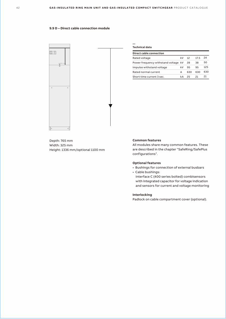
42 G A S - I N S U L A T E D R I N G M A I N U N I T A N D G A S - I N S U L A T E D C O M P A C T S W I T C H G E A R P R O D U C T C A T A L O G U E
9.9 D – Direct cable connection module
Depth: 765 mmWidth: 325 mmHeight: 1336 mm/optional 1100 mm
Direct cable connection
Rated voltage
Power frequency withstand voltage
Impulse withstand voltage
Rated normal current
Short time current 3 sec.
kV
kV
kV
A
kA
12
28
95
630
25
17.5
38
95
630
21
24
50
125
630
21
Common featuresAll modules share many common features. These are described in the chapter “SafeRing/SafePlus configurations”.
Optional features• Bushings for connection of external busbars• Cable bushings:
Interface C (400 series bolted) combisensors with integrated capacitor for voltage indication and sensors for current and voltage monitoring
InterlockingPadlock on cable compartment cover (optional).
—Technical data
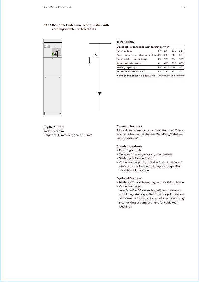
S A F E P L U S M O D U L E S 43
Direct cable connection with earthing switch
Rated voltage
Power frequency withstand voltage
Impulse withstand voltage
Rated normal current
Making capacity
Short time current 3 sec.
Number of mechanical operations
kV
kV
kV
A
kA
kA
1000 close/open manual
12
28
95
630
62.5
25
17.5
38
95
630
50
21
24
50
125
630
50
21
Common featuresAll modules share many common features. These are described in the chapter “SafeRing/SafePlus configurations”.
Standard features• Earthing switch• Two position single spring mechanism• Switch position indication• Cable bushings horizontal in front, Interface C
(400 series bolted) with integrated capacitor for voltage indication
Optional features• Bushings for cable testing, incl. earthing device• Cable bushings:
Interface C (400 series bolted) combisensors with integrated capacitor for voltage indication and sensors for current and voltage monitoring
• Interlocking of compartment for cable test bushings
—Technical data
9.10.1 De – Direct cable connection module with earthing switch – technical data
Depth: 765 mmWidth: 325 mmHeight: 1336 mm/optional 1100 mm
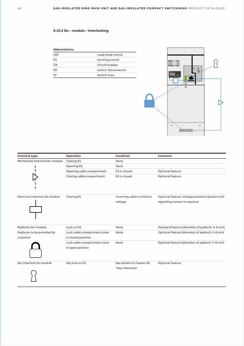
44 G A S - I N S U L A T E D R I N G M A I N U N I T A N D G A S - I N S U L A T E D C O M P A C T S W I T C H G E A R P R O D U C T C A T A L O G U E
9.10.2 De – module – interlocking
Interlock type
Mechanical interlock De-module
Electrical interlock De-module
Padlocks De-module
Padlocks to be provided by
customer
Key interlock De-module
Operation
Closing ES
Opening ES
Opening cable compartment
Closing cable compartment
Closing ES
Lock on ES
Lock cable compartment cover
in closed position
Lock cable compartment cover
in open position
Key lock on ES
Condition
None
None
ES is closed
ES is closed
Incoming cable is without
voltage
None
None
None
See details in chapter 28
“Key interlocks”
Comment
Optional feature
Optional feature
Optional feature. Voltage presence System with
signalling contact is required.
Standard feature (diameter of padlock: 4-8 mm)
Optional feature (diameter of padlock: 4-8 mm)
Optional feature (diameter of padlock: 4-8 mm)
Optional feature
Abbreviations
LBS
ES
CB
SD
SF
Load break switch
Earthing switch
Circuit breaker
Switch-disconnector
Switch-fuse
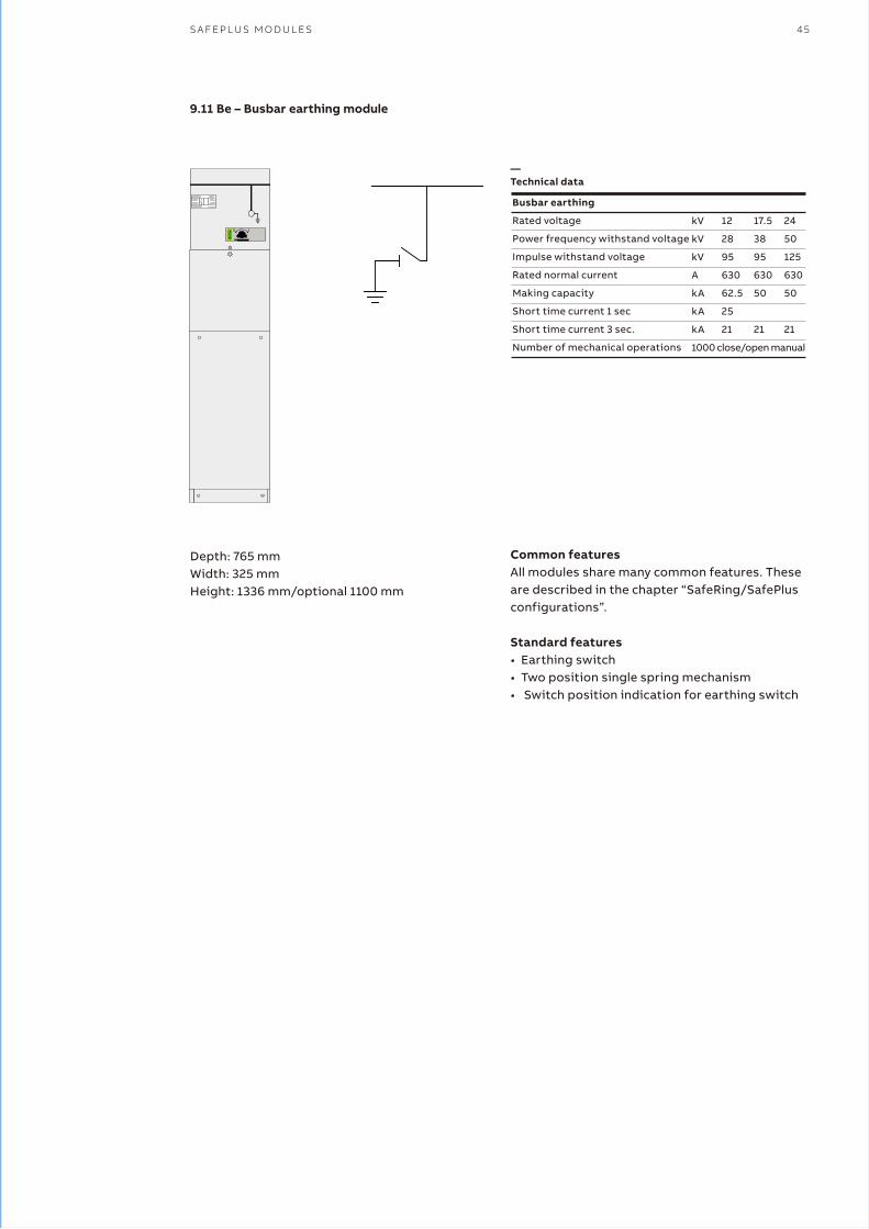
S A F E P L U S M O D U L E S 45
9.11 Be – Busbar earthing module
Depth: 765 mmWidth: 325 mmHeight: 1336 mm/optional 1100 mm
Busbar earthing
Rated voltage
Power frequency withstand voltage
Impulse withstand voltage
Rated normal current
Making capacity
Short time current 1 sec
Short time current 3 sec.
Number of mechanical operations
kV
kV
kV
A
kA
kA
kA
1000 close/open manual
12
28
95
630
62.5
25
21
17.5
38
95
630
50
21
24
50
125
630
50
21
Common featuresAll modules share many common features. These are described in the chapter “SafeRing/SafePlus configurations”.
Standard features• Earthing switch• Two position single spring mechanism• Switch position indication for earthing switch
—Technical data
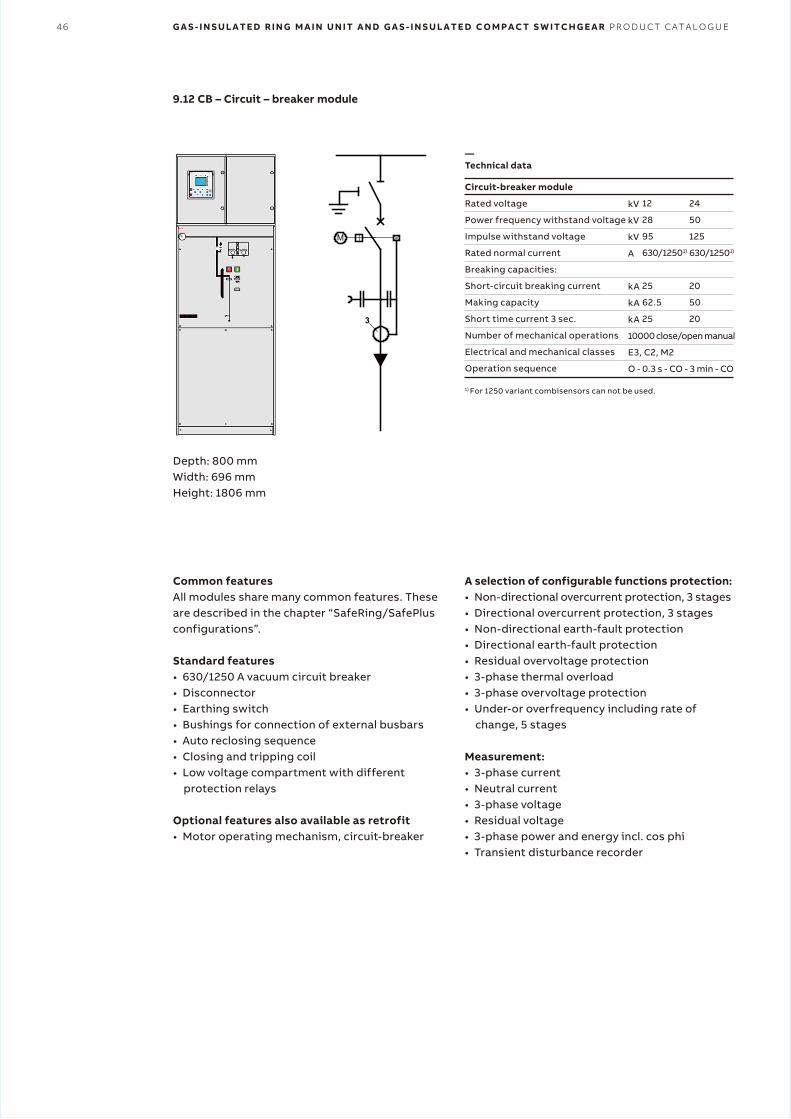
46 G A S - I N S U L A T E D R I N G M A I N U N I T A N D G A S - I N S U L A T E D C O M P A C T S W I T C H G E A R P R O D U C T C A T A L O G U E
9.12 CB – Circuit – breaker module
Depth: 800 mmWidth: 696 mmHeight: 1806 mm
1) For 1250 variant combisensors can not be used.
Common featuresAll modules share many common features. These are described in the chapter “SafeRing/SafePlus configurations”.
Standard features• 630/1250 A vacuum circuit breaker• Disconnector• Earthing switch• Bushings for connection of external busbars• Auto reclosing sequence• Closing and tripping coil• Low voltage compartment with different
protection relays
Optional features also available as retrofit• Motor operating mechanism, circuit-breaker
Circuit-breaker module
Rated voltage
Power frequency withstand voltage
Impulse withstand voltage
Rated normal current
Breaking capacities:
Short-circuit breaking current
Making capacity
Short time current 3 sec.
Number of mechanical operations
Electrical and mechanical classes
Operation sequence
kV
kV
kV
A
kA
kA
kA
10000 close/open manual
E3, C2, M2
O - 0.3 s - CO - 3 min - CO
12
28
95
630/12501)
25
62.5
25
24
50
125
630/12501)
20
50
20
A selection of configurable functions protection:• Non-directional overcurrent protection, 3 stages• Directional overcurrent protection, 3 stages• Non-directional earth-fault protection• Directional earth-fault protection• Residual overvoltage protection• 3-phase thermal overload• 3-phase overvoltage protection• Under-or overfrequency including rate of
change, 5 stages
Measurement:• 3-phase current• Neutral current• 3-phase voltage• Residual voltage• 3-phase power and energy incl. cos phi• Transient disturbance recorder
—Technical data
M
3
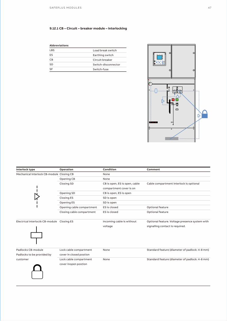
S A F E P L U S M O D U L E S 47
9.12.1 CB – Circuit – breaker module – interlocking
Interlock type
Mechanical interlock CB-module
Electrical interloctk CB-module
Padlocks CB-module
Padlocks to be provided by
customer
Operation
Closing CB
Opening CB
Closing SD
Opening SD
Closing ES
Opening ES
Opening cable compartment
Closing cable compartment
Closing ES
Lock cable compartment
cover in closed postion
Lock cable compartment
cover inopen postion
Condition
None
None
CB is open, ES is open, cable
compartment cover is on
CB is open, ES is open
SD is open
SD is open
ES is closed
ES is closed
Incoming cable is without
voltage
None
None
Comment
Cable compartment interlock is optional
Optional feature
Optional feature
Optional feature. Voltage presence system with
signalling contact is required.
Standard feature (diameter of padlock: 4-8 mm)
Standard feature (diameter of padlock: 4-8 mm)
Abbreviations
LBS
ES
CB
SD
SF
Load break switch
Earthing switch
Circuit breaker
Switch-disconnector
Switch-fuse
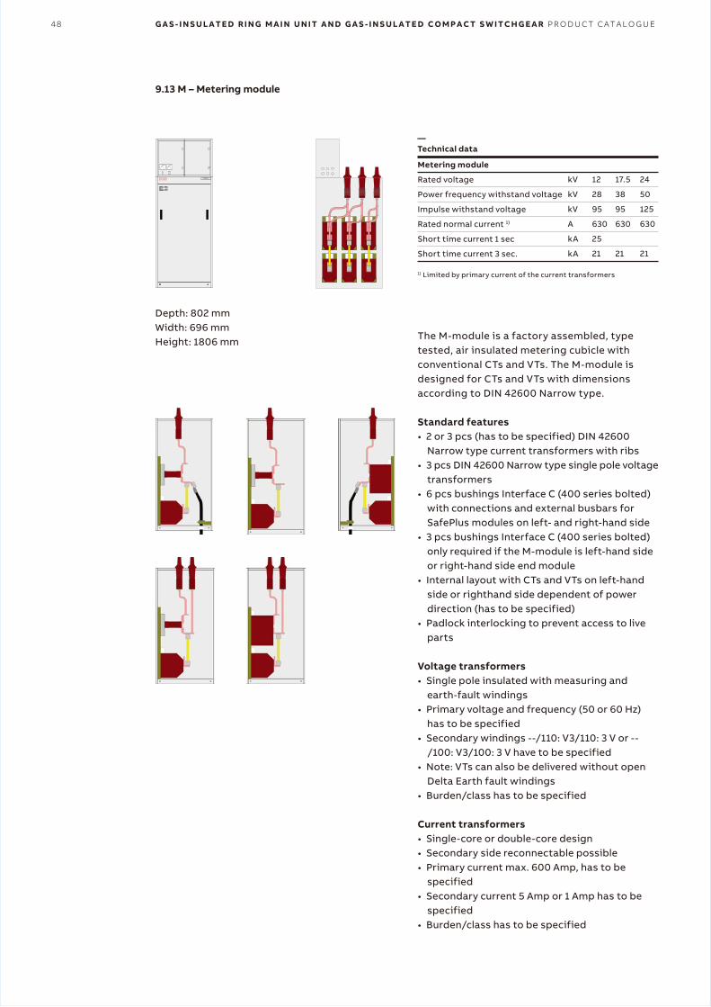
48 G A S - I N S U L A T E D R I N G M A I N U N I T A N D G A S - I N S U L A T E D C O M P A C T S W I T C H G E A R P R O D U C T C A T A L O G U E
9.13 M – Metering module
Depth: 802 mmWidth: 696 mmHeight: 1806 mm
1) Limited by primary current of the current transformers
Metering module
Rated voltage
Power frequency withstand voltage
Impulse withstand voltage
Rated normal current 1)
Short time current 1 sec
Short time current 3 sec.
kV
kV
kV
A
kA
kA
12
28
95
630
25
21
17.5
38
95
630
21
24
50
125
630
21
The M-module is a factory assembled, type tested, air insulated metering cubicle with conventional CTs and VTs. The M-module is designed for CTs and VTs with dimensions according to DIN 42600 Narrow type.
Standard features• 2 or 3 pcs (has to be specified) DIN 42600
Narrow type current transformers with ribs• 3 pcs DIN 42600 Narrow type single pole voltage
transformers• 6 pcs bushings Interface C (400 series bolted)
with connections and external busbars for SafePlus modules on left- and right-hand side
• 3 pcs bushings Interface C (400 series bolted) only required if the M-module is left-hand side or right-hand side end module
• Internal layout with CTs and VTs on left-hand side or righthand side dependent of power direction (has to be specified)
• Padlock interlocking to prevent access to live parts
Voltage transformers• Single pole insulated with measuring and
earth-fault windings• Primary voltage and frequency (50 or 60 Hz)
has to be specified• Secondary windings --/110: V3/110: 3 V or --
/100: V3/100: 3 V have to be specified• Note: VTs can also be delivered without open
Delta Earth fault windings• Burden/class has to be specified
Current transformers• Single-core or double-core design• Secondary side reconnectable possible• Primary current max. 600 Amp, has to be
specified• Secondary current 5 Amp or 1 Amp has to be
specified• Burden/class has to be specified
��� SafePlus
—Technical data
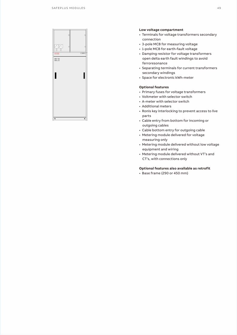
S A F E P L U S M O D U L E S 49
Low voltage compartment• Terminals for voltage transformers secondary
connection• 3-pole MCB for measuring voltage• 1-pole MCB for earth-fault voltage• Damping resistor for voltage transformers
open delta earth fault windings to avoid ferroresonance
• Separating terminals for current transformers secondary windings
• Space for electronic kWh-meter
Optional features• Primary fuses for voltage transformers• Voltmeter with selector switch• A-meter with selector switch• Additional meters• Ronis key interlocking to prevent access to live
parts• Cable entry from bottom for incoming or
outgoing cables• Cable bottom entry for outgoing cable• Metering module delivered for voltage
measuring only• Metering module delivered without low voltage
equipment and wiring• Metering module delivered without VT’s and
CT’s, with connections only
Optional features also available as retrofit• Base frame (290 or 450 mm)
��� SafePlus

50 G A S - I N S U L A T E D R I N G M A I N U N I T A N D G A S - I N S U L A T E D C O M P A C T S W I T C H G E A R P R O D U C T C A T A L O G U E
—10 Mini – metering (integrated metering)
For this solution, either a base frame or cable trench is needed. The switchgear is equipped with special support bars for transport.
FeaturesRing main unit configurations such as CCVm with breaker and CCFm with fuses.• Solution is available for 3-or 4-way units for 12
and 24 kV.
The measurement has to be taken from the right-hand side.
No need for separate metering module in typical ring main unit applications with one incoming/ outgoing feeder.
Integrated voltage and current transformers used for tariff metering.• CTs Class 0.2 S• VTs Class 0.2 (touch proof design)
Customer benefits• Space saving with one common SF6 gas tank
solution• Arc suppressors in cable switch panels for
increased personnel safety• Manometer with visible indication of arc
suppressor• Factory mounted solution with integrated VTs
& CTs for reduced installation time on site• Compact dimensions• Cost saving with reduced footprint• Standard design with short lead time• Arc-proof tested solution
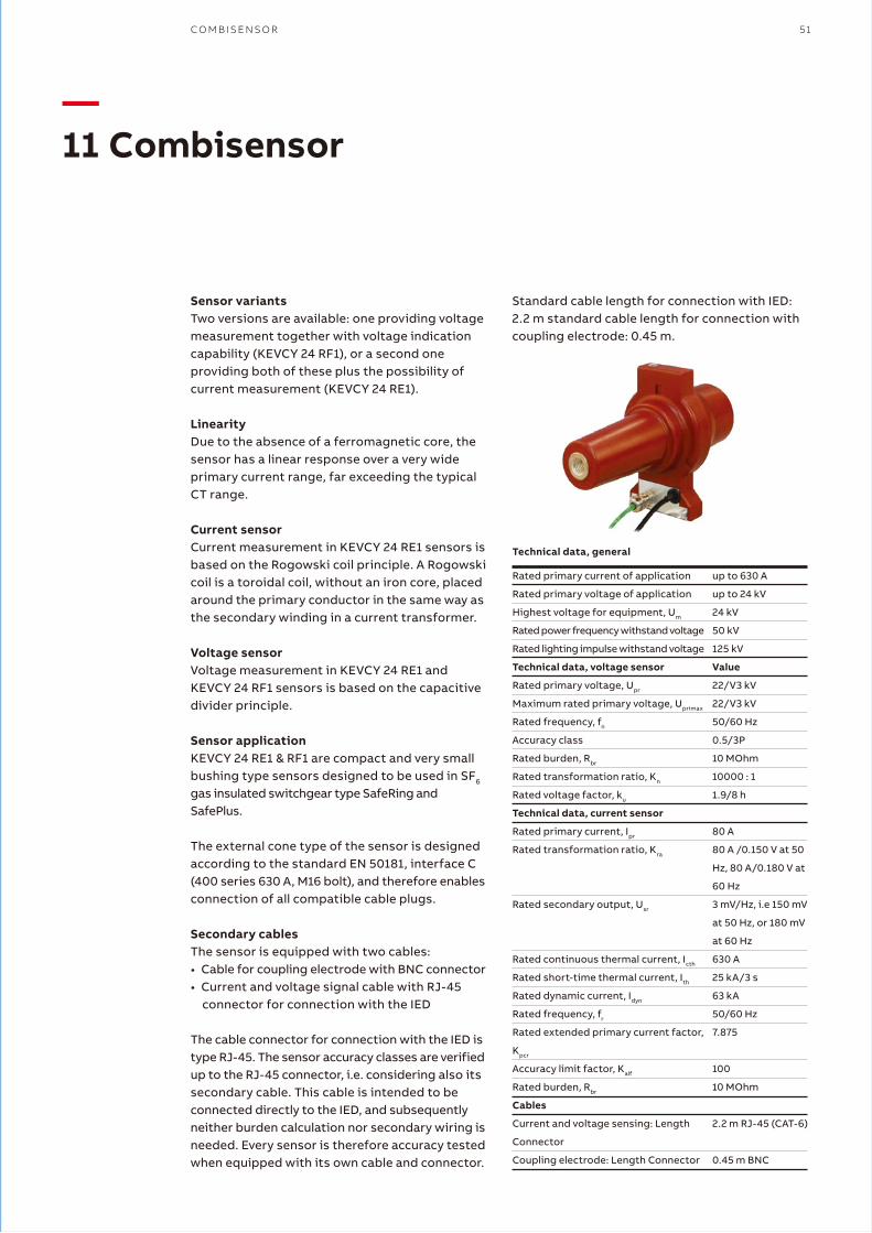
C O M B I S E N S O R 51
—11 Combisensor
Rated primary current of application
Rated primary voltage of application
Highest voltage for equipment, Um
Rated power frequency withstand voltage
Rated lighting impulse withstand voltage
Technical data, voltage sensor
Rated primary voltage, Upr
Maximum rated primary voltage, Uprimax
Rated frequency, fn
Accuracy class
Rated burden, Rbr
Rated transformation ratio, Kn
Rated voltage factor, ku
Technical data, current sensor
Rated primary current, Ipr
Rated transformation ratio, Kra
Rated secondary output, Usr
Rated continuous thermal current, Icth
Rated short-time thermal current, Ith
Rated dynamic current, Idyn
Rated frequency, fr
Rated extended primary current factor,
Kpcr
Accuracy limit factor, Kalf
Rated burden, Rbr
Cables
Current and voltage sensing: Length
Connector
Coupling electrode: Length Connector
up to 630 A
up to 24 kV
24 kV
50 kV
125 kV
Value
22/V3 kV
22/V3 kV
50/60 Hz
0.5/3P
10 MOhm
10000 : 1
1.9/8 h
80 A
80 A /0.150 V at 50
Hz, 80 A/0.180 V at
60 Hz
3 mV/Hz, i.e 150 mV
at 50 Hz, or 180 mV
at 60 Hz
630 A
25 kA/3 s
63 kA
50/60 Hz
7.875
100
10 MOhm
2.2 m RJ-45 (CAT-6)
0.45 m BNC
Sensor variantsTwo versions are available: one providing voltagemeasurement together with voltage indication capability (KEVCY 24 RF1), or a second one providing both of these plus the possibility of current measurement (KEVCY 24 RE1).
LinearityDue to the absence of a ferromagnetic core, the sensor has a linear response over a very wide primary current range, far exceeding the typical CT range.
Current sensorCurrent measurement in KEVCY 24 RE1 sensors is based on the Rogowski coil principle. A Rogowski coil is a toroidal coil, without an iron core, placed around the primary conductor in the same way as the secondary winding in a current transformer.
Voltage sensorVoltage measurement in KEVCY 24 RE1 and KEVCY 24 RF1 sensors is based on the capacitive divider principle.
Sensor applicationKEVCY 24 RE1 & RF1 are compact and very small bushing type sensors designed to be used in SF6 gas insulated switchgear type SafeRing and SafePlus.
The external cone type of the sensor is designed according to the standard EN 50181, interface C (400 series 630 A, M16 bolt), and therefore enables connection of all compatible cable plugs.
Secondary cablesThe sensor is equipped with two cables:• Cable for coupling electrode with BNC connector• Current and voltage signal cable with RJ-45
connector for connection with the IED
The cable connector for connection with the IED is type RJ-45. The sensor accuracy classes are verified up to the RJ-45 connector, i.e. considering also its secondary cable. This cable is intended to be connected directly to the IED, and subsequently neither burden calculation nor secondary wiring is needed. Every sensor is therefore accuracy tested when equipped with its own cable and connector.
Technical data, general
Standard cable length for connection with IED: 2.2 m standard cable length for connection with coupling electrode: 0.45 m.
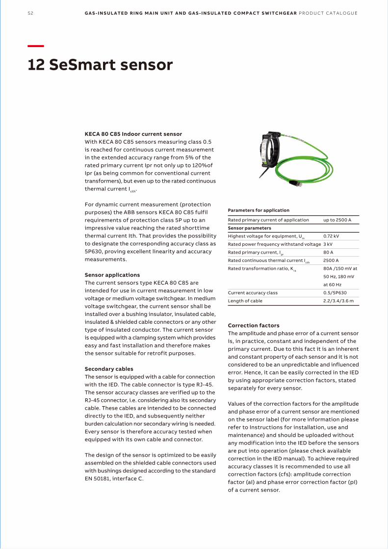
52 G A S - I N S U L A T E D R I N G M A I N U N I T A N D G A S - I N S U L A T E D C O M P A C T S W I T C H G E A R P R O D U C T C A T A L O G U E
—12 SeSmart sensor
Rated primary current of application
Sensor parameters
Highest voltage for equipment, Um
Rated power frequency withstand voltage
Rated primary current, Ipr
Rated continuous thermal current Icth
Rated transformation ratio, Kra
Current accuracy class
Length of cable
up to 2500 A
0.72 kV
3 kV
80 A
2500 A
80A /150 mV at
50 Hz, 180 mV
at 60 Hz
0.5/5P630
2.2/3.4/3.6 m
KECA 80 C85 Indoor current sensorWith KECA 80 C85 sensors measuring class 0.5 is reached for continuous current measurement in the extended accuracy range from 5% of the rated primary current Ipr not only up to 120%of Ipr (as being common for conventional currenttransformers), but even up to the rated continuous thermal current Icth.
For dynamic current measurement (protection purposes) the ABB sensors KECA 80 C85 fulfil requirements of protection class 5P up to an impressive value reaching the rated shorttimethermal current Ith. That provides the possibility to designate the corresponding accuracy class as 5P630, proving excellent linearity and accuracy measurements.
Sensor applicationsThe current sensors type KECA 80 C85 are intended for use in current measurement in low voltage or medium voltage switchgear. In medium voltage switchgear, the current sensor shall be installed over a bushing insulator, insulated cable, insulated & shielded cable connectors or any other type of insulated conductor. The current sensor is equipped with a clamping system which provides easy and fast installation and therefore makes the sensor suitable for retrofit purposes.
Secondary cablesThe sensor is equipped with a cable for connection with the IED. The cable connector is type RJ-45. The sensor accuracy classes are verified up to the RJ-45 connector, i.e. considering also its secondary cable. These cables are intended to be connected directly to the IED, and subsequently neither burden calculation nor secondary wiring is needed. Every sensor is therefore accuracy tested when equipped with its own cable and connector.
The design of the sensor is optimized to be easily assembled on the shielded cable connectors used with bushings designed according to the standard EN 50181, interface C.
Parameters for application
Correction factorsThe amplitude and phase error of a current sensor is, in practice, constant and independent of the primary current. Due to this fact it is an inherent and constant property of each sensor and it is not considered to be an unpredictable and influenced error. Hence, it can be easily corrected in the IED by using appropriate correction factors, stated separately for every sensor.
Values of the correction factors for the amplitude and phase error of a current sensor are mentioned on the sensor label (for more information please refer to Instructions for installation, use and maintenance) and should be uploaded without any modification into the IED before the sensors are put into operation (please check available correction in the IED manual). To achieve required accuracy classes it is recommended to use all correction factors (cfs): amplitude correction factor (aI) and phase error correction factor (pI) of a current sensor.
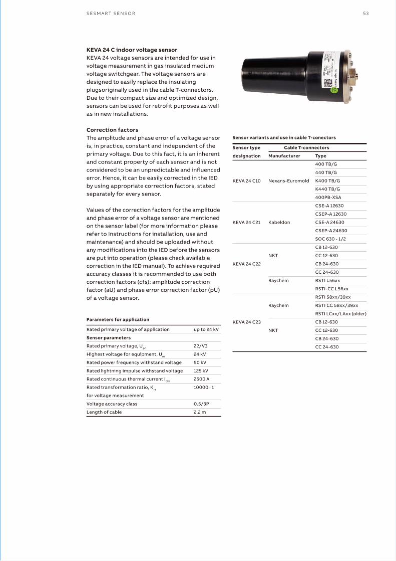
S E S M A R T S E N S O R 53
Rated primary voltage of application
Sensor parameters
Rated primary voltage, Upn
Highest voltage for equipment, Um
Rated power frequency withstand voltage
Rated lightning impulse withstand voltage
Rated continuous thermal current Icth
Rated transformation ratio, Kra
for voltage measurement
Voltage accuracy class
Length of cable
up to 24 kV
22/V3
24 kV
50 kV
125 kV
2500 A
10000 : 1
0.5/3P
2.2 m
KEVA 24 C indoor voltage sensorKEVA 24 voltage sensors are intended for use in voltage measurement in gas insulated medium voltage switchgear. The voltage sensors are designed to easily replace the insulating plugsoriginally used in the cable T-connectors. Due to their compact size and optimized design, sensors can be used for retrofit purposes as well as in new installations.
Correction factorsThe amplitude and phase error of a voltage sensor is, in practice, constant and independent of the primary voltage. Due to this fact, it is an inherent and constant property of each sensor and is not considered to be an unpredictable and influenced error. Hence, it can be easily corrected in the IED by using appropriate correction factors, stated separately for every sensor.
Values of the correction factors for the amplitude and phase error of a voltage sensor are mentioned on the sensor label (for more information please refer to Instructions for installation, use and maintenance) and should be uploaded without any modifications into the IED before the sensors are put into operation (please check available correction in the IED manual). To achieve required accuracy classes it is recommended to use both correction factors (cfs): amplitude correction factor (aU) and phase error correction factor (pU) of a voltage sensor.
Parameters for application
Sensor type
designation
KEVA 24 C10
KEVA 24 C21
KEVA 24 C22
KEVA 24 C23
Manufacturer
Nexans-Euromold
Kabeldon
NKT
Raychem
Raychem
NKT
Type
400 TB/G
440 TB/G
K400 TB/G
K440 TB/G
400PB-XSA
CSE-A 12630
CSEP-A 12630
CSE-A 24630
CSEP-A 24630
SOC 630 - 1/2
CB 12-630
CC 12-630
CB 24-630
CC 24-630
RSTI L56xx
RSTI-CC L56xx
RSTI 58xx/39xx
RSTI CC 58xx/39xx
RSTI LCxx/LAxx (older)
CB 12-630
CC 12-630
CB 24-630
CC 24-630
Sensor variants and use in cable T-conectors
Cable T-connectors
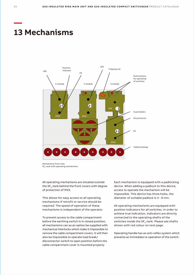
—13 Mechanisms
All operating mechanisms are situated outside the SF6-tank behind the front covers with degree of protection of IP2X.
This allows for easy access to all operating mechanisms if retrofit or service should be required. The speed of operation of these mechanisms is independent of the operator.
To prevent access to the cable compartment before the earthing switch is in closed position, all mechanisms can as an option be supplied with mechanical interlocks which make it impossible to remove the cable compartment covers. It will then also be impossible to operate load break/ disconnector switch to open position before the cable compartment cover is mounted properly.
Each mechanism is equipped with a padlocking device. When adding a padlock to this device, access to operate the mechanism will be impossible. This device has three holes, the diameter of suitable padlock is 4 - 8 mm.
All operating mechanisms are equipped with position indicators for all switches. In order to achieve true indication, indicators are directly connected to the operating shafts of theswitches inside the SF6-tank. Please see shafts shown with red colour on next page.
Operating handle has an anti-reflex system which prevents an immediate re-operation of the switch.
54 G A S - I N S U L A T E D R I N G M A I N U N I T A N D G A S - I N S U L A T E D C O M P A C T S W I T C H G E A R P R O D U C T C A T A L O G U E
ESLBS
LBSPositionindicator
Tripping coil
Push buttonsfor operating of switches
Fuse holders
Disconnector
ES
Cable bushings
3PKE
3PKE
3PAE
2PA
C-module F-module V-module
Mechanisms front view.SF6-tank with operating mechanisms.

Cable switch module and busbar sectionalizer with load break switchThe mechanism (3PKE) has two operating shafts: the upper one for the load break switch and the lower one for the earthing switch.
Both shafts are single spring operated and operate one common shaft which is directly connected to the three position switch (CFE-C) inside the SF6-tank. When both load break switch and earthing switch are in open position, the switch satisfies the specifications of disconnector.
Due to the mechanical interlock between the upper and lower operating shaft, it is impossible to operate the load break switch when the earthing switch is in earthed position or to operate the earthing switch when the load break switch is in closed position.
Switch-fuse moduleThe mechanism (3PAE) has two operating shafts: the upper one for the load break switch and the lower one for the earthing switch.
The upper one operates two springs: one for closing and one for opening. Both springs are charged in one operation. By means of mechanical push buttons it is then possible to close and open the load break switch.
M E C H A N I S M S 55
C-mechanism
SF6Air
F-mechanism
SF6Air
The opening spring is always charged when the load break switch is in closed position and will be ready to open the load break switch immediately if one of the HV-fuse-links blows. The blown fuse-link (s) has/have to be replaced before the operator will be able to close the load break switch again. According to IEC 60282-1, all three fuse-links should be replaced, even if only one or two have operated.
The lower shaft is single spring operated. Both operating shafts operate one common shaft which is directly connected to the three position switch (CFE-F) inside the SF6-tank. Due to the mechanical interlock between the upper and lower operating shaft, it is impossible to operate the load break switch when the earthing switch is in earthed position or to operate the earthing switch when the load break switch is in closed position.
It will also be impossible to access the fuse compartment before the earthing switch is in closed position.

56 G A S - I N S U L A T E D R I N G M A I N U N I T A N D G A S - I N S U L A T E D C O M P A C T S W I T C H G E A R P R O D U C T C A T A L O G U E
Vacuum circuit breaker and busbar sectionalizer with circuit breakerThese two modules have two mechanisms: the upper one (2PA) with one operating shaft is for the circuit-breaker and the lower one (3PKE) with two operating shafts is for the disconnector and earthing switch.
The upper mechanism has two operating spring: one for closing and one for opening.
Both springs are charged in one operation. By means of mechanical push buttons it is then possible to close and open the circuit breaker.
The opening spring is always charged when the circuit breaker is in closed position and will be ready to open immediately if the protection relay gives a trip signal.
However, a quick reclosing is not possible. If the mechanism is equipped with a motor operation a reclosing will take approximately 10 seconds.
The lower mechanism is identical to the one described above for the cable switch module.
There is a mechanical interlock between these two mechanisms which prevents operating of the disconnector and earthing switch when the circuit breaker is in closed position. When the earthing switch is in closed position it will be impossible to operate the disconnector, but the circuit breaker can be closed for testing purpose.
V-mechanism
SF6 Air
High duty vacuum circuit-breaker V25/V20This module has two mechanisms: the upper one (EL2) is for the circuit-breaker and the lower one (3PKE) with two operating shafts is for the disconnector and earthing switch. The vacuum circuit-breaker has the possibility of rapid autoreclosing duty.
By means of mechanical push buttons it is possible to close and open the circuit-breaker. The opening spring is always charged when the circuit-breaker is in closed position and will be ready to open immediately if the protection relay gives a trip signal. If the mechanism is recharged after closing, it is possible to perform open - close - open sequence.
The lower mechanism is identical to the one described above for the cable switch module.
There is a mechanical interlock between these two mechanisms which prevents operating of the disconnector and earthing switch when the circuit-breaker is in closed position. When the earthing switch is in closed position it will beimpossible to operate the disconnector, but the circuitbreaker can be closed for testing purpose.
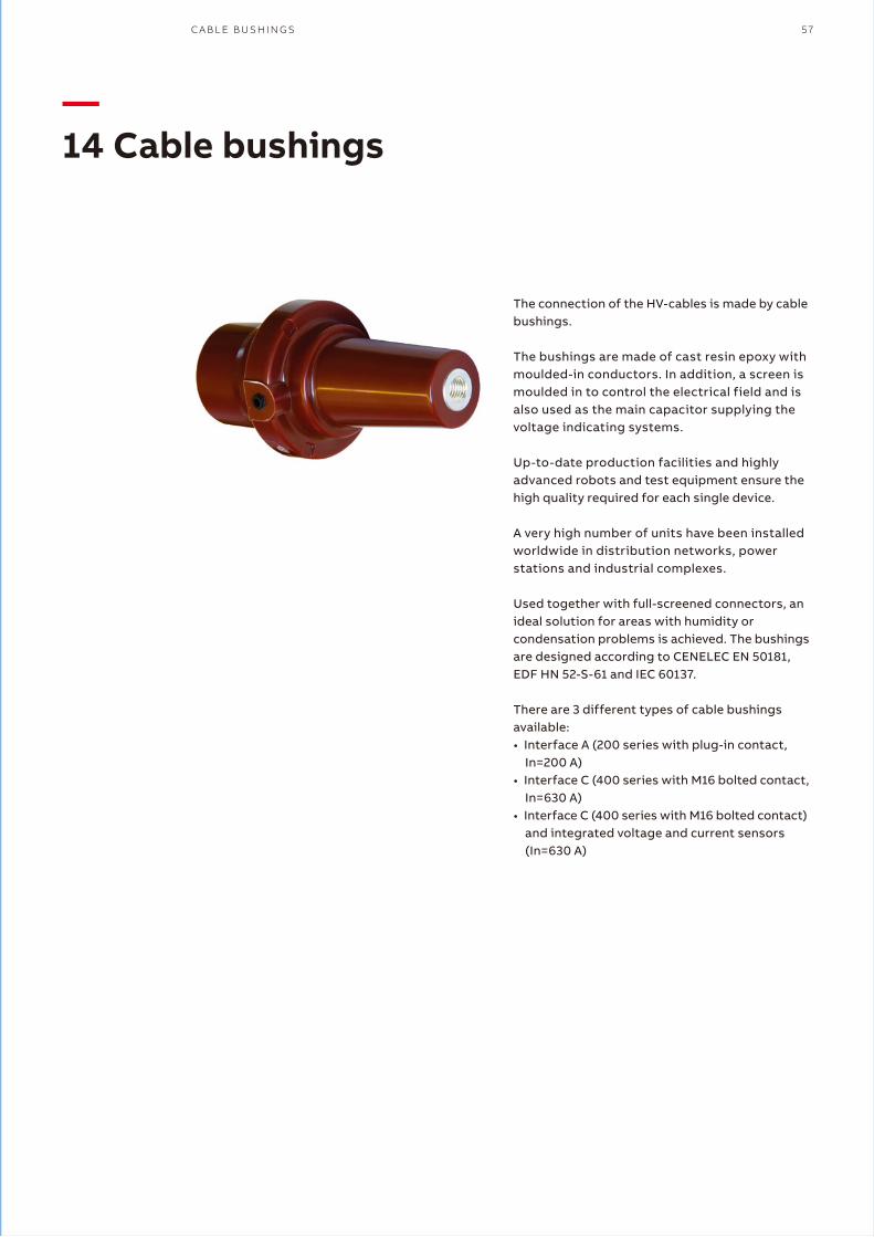
—14 Cable bushings
The connection of the HV-cables is made by cable bushings.
The bushings are made of cast resin epoxy with moulded-in conductors. In addition, a screen is moulded in to control the electrical field and is also used as the main capacitor supplying the voltage indicating systems.
Up-to-date production facilities and highly advanced robots and test equipment ensure the high quality required for each single device.
A very high number of units have been installed worldwide in distribution networks, power stations and industrial complexes.
Used together with full-screened connectors, an ideal solution for areas with humidity or condensation problems is achieved. The bushings are designed according to CENELEC EN 50181, EDF HN 52-S-61 and IEC 60137.
There are 3 different types of cable bushings available:• Interface A (200 series with plug-in contact,
In=200 A)• Interface C (400 series with M16 bolted contact,
In=630 A)• Interface C (400 series with M16 bolted contact)
and integrated voltage and current sensors (In=630 A)
C A B L E B U S H I N G S 57

—15 Cable termination
58 G A S - I N S U L A T E D R I N G M A I N U N I T A N D G A S - I N S U L A T E D C O M P A C T S W I T C H G E A R P R O D U C T C A T A L O G U E
The following cable bushings are available as standard:• Interface A with plug• 200 series, In = 200 A• Standard on F module (In = 200 A)• The yellow area indicates the silver coated
contact spring• Cable cross-section: See tables 16.1.1 and 16.2.1
• Interface C with M16x2 metric threads• 400 series, In = 630 A• Standard on C, V (In=630 A), D and De modules;
and for top extension• Cable cross-section: see tables 16.1.2 and
16.2.2.
The installation instructions from the manufacturer of cable terminations must be followed. Be sure to lubricate the bushings thoroughly with the silicone supplied.
Where cables are not connected, the earthing switch must be locked in closed position or the bushings must be fitted with dead end receptacles before the unit is energized.
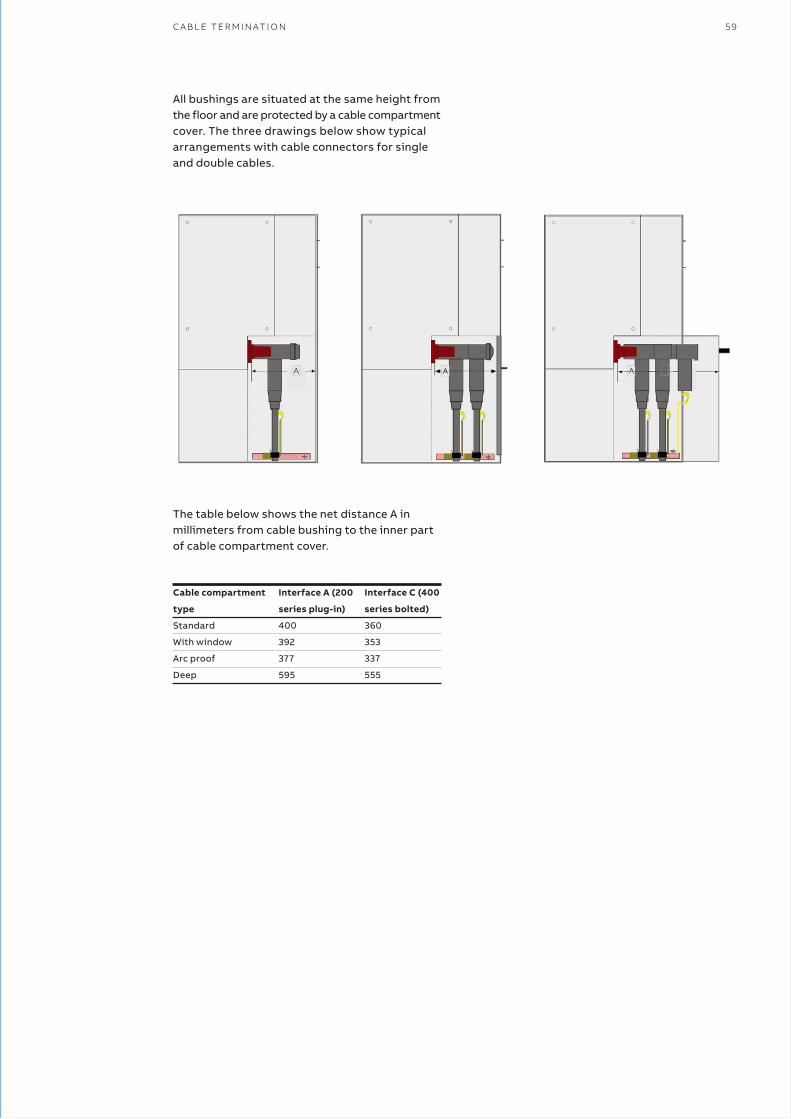
All bushings are situated at the same height from the floor and are protected by a cable compartment cover. The three drawings below show typical arrangements with cable connectors for single and double cables.
The table below shows the net distance A in millimeters from cable bushing to the inner part of cable compartment cover.
C A B L E T E R M I N A T I O N 59
Cable compartment
type
Standard
With window
Arc proof
Deep
Interface A (200
series plug-in)
400
392
377
595
Interface C (400
series bolted)
360
353
337
555
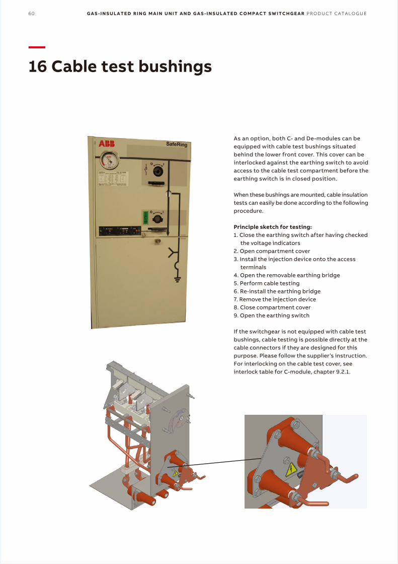
60 G A S - I N S U L A T E D R I N G M A I N U N I T A N D G A S - I N S U L A T E D C O M P A C T S W I T C H G E A R P R O D U C T C A T A L O G U E
—16 Cable test bushings
As an option, both C- and De-modules can be equipped with cable test bushings situated behind the lower front cover. This cover can be interlocked against the earthing switch to avoid access to the cable test compartment before the earthing switch is in closed position.
When these bushings are mounted, cable insulation tests can easily be done according to the following procedure.
Principle sketch for testing:1. Close the earthing switch after having checked
the voltage indicators2. Open compartment cover3. Install the injection device onto the access
terminals4. Open the removable earthing bridge5. Perform cable testing6. Re-install the earthing bridge7. Remove the injection device8. Close compartment cover9. Open the earthing switch
If the switchgear is not equipped with cable test bushings, cable testing is possible directly at the cable connectors if they are designed for this purpose. Please follow the supplier’s instruction. For interlocking on the cable test cover, see interlock table for C-module, chapter 9.2.1.

E X T E N S I O N O F S W I T C H G E A R 61
—17 Extension of switchgear
18.1 External busbars on topOn the top of all SafeRing and SafePlus switchgears it is possible as an option to have bushings for connection of external busbars on the left and/or right side.
For a SafePlus switchgear consisting of only one module, only one set of bushings on the top is used.
When bushings are mounted on the top, you will have these possibilities:1. When adding a dead end receptacle to each of
these bushings, SafeRing/SafePlus will be prepared for future busbar extension.
2. With an external busbar kit, it is possible to connect two or more sections.
Since a 5-way switchgear is the maximum size within one common SF6-tank, the busbar kit allows a configuration with more than 5 modules.
The installation of the external busbars has to be done on site. See manual 1VDD006006 GB for installation instructions.
The complete extension kit and the dead end receptacles are fully screened, earthed and insulated. This makes a safe and reliable switchgear extension.
In addition, protection covers are available as an option.
SafePlus switchgear can also be configured as fully modular. This results in a 1250 A busbar rating.
The busbars between the modules and the end adapters used on the left and right side are identical to the parts used in the previous example. For the three modules in the middle, a special cross adapter is used.
The length of the external busbars are dependent on the type of modules to be connected.
Connection by external busbars is available for all modules.
SafePlus prepared for future extension on right hand side
Fully modular SafePlus with external busbar cover
SafePlus with one incomer (C-module), one Metering module(M-module) and three fused T-offs (F-modules), prepared forfuture extension.
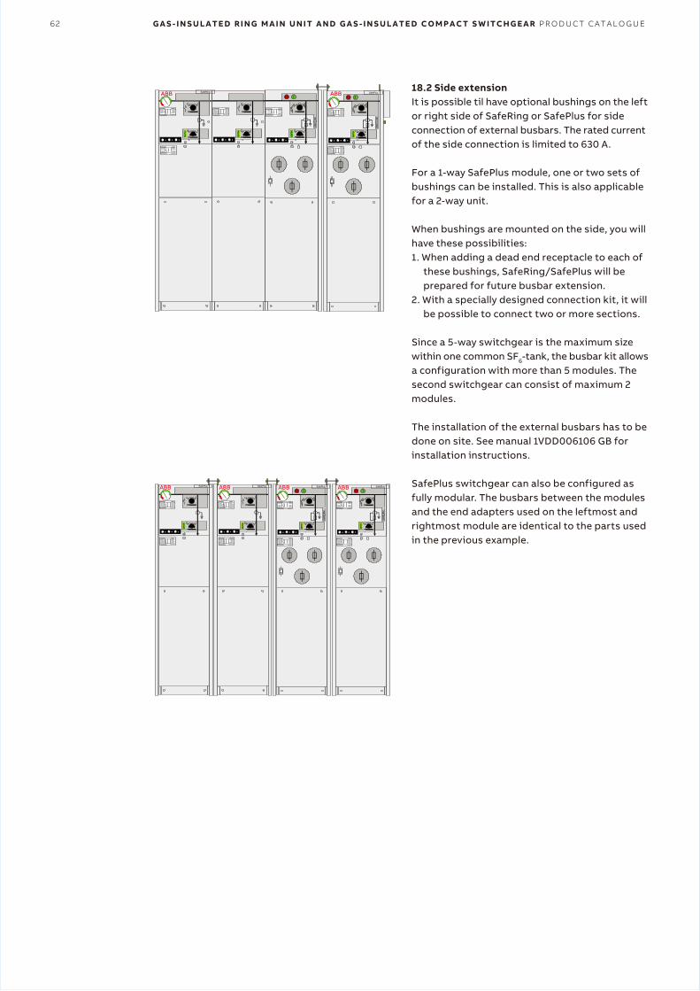
62 G A S - I N S U L A T E D R I N G M A I N U N I T A N D G A S - I N S U L A T E D C O M P A C T S W I T C H G E A R P R O D U C T C A T A L O G U E
18.2 Side extensionIt is possible til have optional bushings on the left or right side of SafeRing or SafePlus for side connection of external busbars. The rated current of the side connection is limited to 630 A.
For a 1-way SafePlus module, one or two sets ofbushings can be installed. This is also applicable for a 2-way unit.
When bushings are mounted on the side, you will have these possibilities:1. When adding a dead end receptacle to each of
these bushings, SafeRing/SafePlus will be prepared for future busbar extension.
2. With a specially designed connection kit, it will be possible to connect two or more sections.
Since a 5-way switchgear is the maximum size within one common SF6-tank, the busbar kit allows a configuration with more than 5 modules. The second switchgear can consist of maximum 2 modules.
The installation of the external busbars has to be done on site. See manual 1VDD006106 GB for installation instructions.
SafePlus switchgear can also be configured as fully modular. The busbars between the modules and the end adapters used on the leftmost and rightmost module are identical to the parts used in the previous example.
SafeRing SafePlus
SafePlusSafePlusSafePlus SafePlusABB ABB ABB ABB
ABB ABB
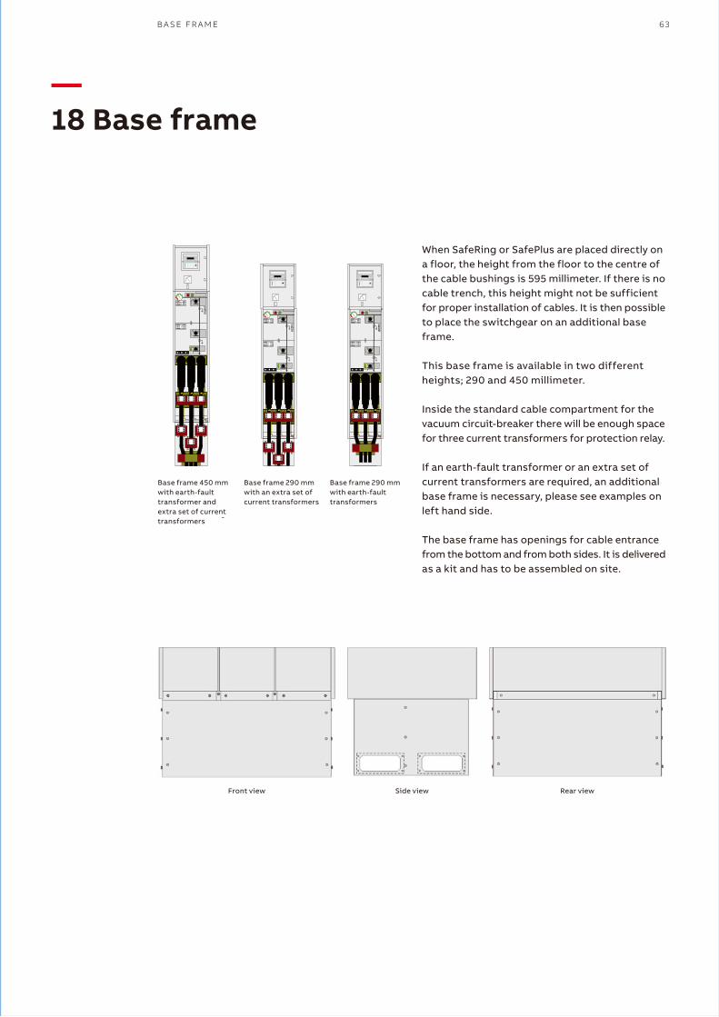
B A S E F R A M E 63
When SafeRing or SafePlus are placed directly on a floor, the height from the floor to the centre of the cable bushings is 595 millimeter. If there is no cable trench, this height might not be sufficient for proper installation of cables. It is then possible to place the switchgear on an additional base frame.
This base frame is available in two different heights; 290 and 450 millimeter.
Inside the standard cable compartment for the vacuum circuit-breaker there will be enough space for three current transformers for protection relay.
If an earth-fault transformer or an extra set of current transformers are required, an additional base frame is necessary, please see examples on left hand side.
The base frame has openings for cable entrance from the bottom and from both sides. It is delivered as a kit and has to be assembled on site.
—18 Base frame
Base frame 450 mmwith earth-fault transformer andextra set of current transformers -
Base frame 290 mmwith an extra set ofcurrent transformers
Base frame 290 mmwith earth-faulttransformers
Front view Side view Rear view
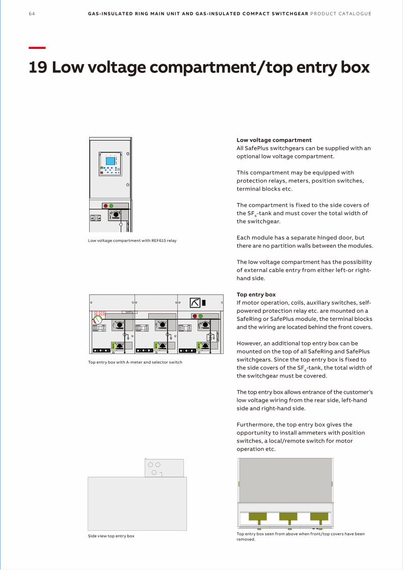
64 G A S - I N S U L A T E D R I N G M A I N U N I T A N D G A S - I N S U L A T E D C O M P A C T S W I T C H G E A R P R O D U C T C A T A L O G U E
—19 Low voltage compartment/top entry box
Low voltage compartmentAll SafePlus switchgears can be supplied with an optional low voltage compartment.
This compartment may be equipped with protection relays, meters, position switches, terminal blocks etc.
The compartment is fixed to the side covers of the SF6-tank and must cover the total width of the switchgear.
Each module has a separate hinged door, but there are no partition walls between the modules.
The low voltage compartment has the possibility of external cable entry from either left-or right- hand side.
Top entry boxIf motor operation, coils, auxiliary switches, self- powered protection relay etc. are mounted on a SafeRing or SafePlus module, the terminal blocks and the wiring are located behind the front covers.
However, an additional top entry box can be mounted on the top of all SafeRing and SafePlus switchgears. Since the top entry box is fixed to the side covers of the SF6-tank, the total width of the switchgear must be covered.
The top entry box allows entrance of the customer’s low voltage wiring from the rear side, left-hand side and right-hand side.
Furthermore, the top entry box gives the opportunity to install ammeters with position switches, a local/remote switch for motor operation etc.
��� SafeRing
Top entry box with A-meter and selector switch
Low voltage compartment with REF615 relay
Side view top entry box Top entry box seen from above when front/top covers have been removed.
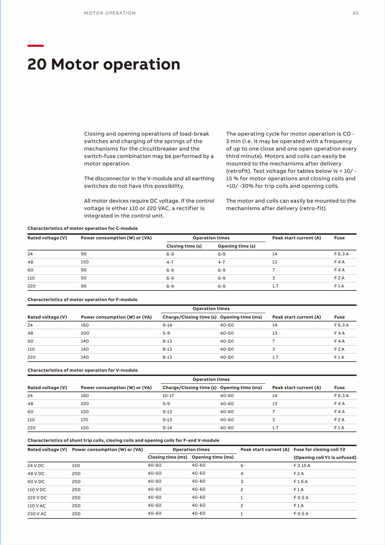
M O T O R O P E R A T I O N 65
—20 Motor operation
Closing and opening operations of load-break switches and charging of the springs of the mechanisms for the circuitbreaker and the switch-fuse combination may be performed by a motor operation.
The disconnector in the V-module and all earthing switches do not have this possibility.
All motor devices require DC voltage. If the control voltage is either 110 or 220 VAC, a rectifier is integrated in the control unit.
The operating cycle for motor operation is CO - 3 min (i.e. it may be operated with a frequency of up to one close and one open operation every third minute). Motors and coils can easily be mounted to the mechanisms after delivery (retrofit). Test voltage for tables below is + 10/ - 15 % for motor operations and closing coils and +10/ -30% for trip coils and opening coils.
The motor and coils can easily be mounted to the mechanisms after delivery (retro-fit).
Rated voltage (V)
24
48
60
110
220
Power consumption (W) or (VA)
90
150
90
90
90
Closing time (s)
6-9
4-7
6-9
6-9
6-9
Opening time (s)
6-9
4-7
6-9
6-9
6-9
Peak start current (A)
14
13
7
3
1.7
Fuse
F 6.3 A
F 4 A
F 4 A
F 2 A
F 1 A
Rated voltage (V)
24
48
60
110
220
Power consumption (W) or (VA)
160
200
140
140
140
Charge/Closing time (s)
9-14
5-9
8-13
8-13
8-13
Opening time (ms)
40-60
40-60
40-60
40-60
40-60
Peak start current (A)
14
13
7
3
1.7
Fuse
F 6.3 A
F 4 A
F 4 A
F 2 A
F 1 A
Rated voltage (V)
24
48
60
110
220
Power consumption (W) or (VA)
180
220
150
170
150
Charge/Closing time (s)
10-17
5-9
9-13
9-13
9-14
Opening time (ms)
40-60
40-60
40-60
40-60
40-60
Peak start current (A)
14
13
7
3
1.7
Fuse
F 6.3 A
F 4 A
F 4 A
F 2 A
F 1 A
Rated voltage (V)
24 V DC
48 V DC
60 V DC
110 V DC
220 V DC
110 V AC
230 V AC
Power consumption (W) or (VA)
150
200
200
200
200
200
200
Closing time (ms)
40-60
40-60
40-60
40-60
40-60
40-60
40-60
Opening time (ms)
40-60
40-60
40-60
40-60
40-60
40-60
40-60
Peak start current (A)
6
4
3
2
1
2
1
Fuse for closing coil Y2
(Opening coil Y1 is unfused)
F 3.15 A
F 2 A
F 1.6 A
F 1 A
F 0.5 A
F 1 A
F 0.5 A
��� SafePlus
SafePlus������ ��� SafePlus��� SafePlus���SafePlusSafePlus
��� SafePlus��� SafePlus ��� SafePlus
Characteristics of motor operation for C-module
Operation times
Operation times
Operation times
Operation times
Characteristics of motor operation for F-module
Characteristics of motor operation for V-module
Characteristics of shunt trip coils, closing coils and opening coils for F-and V-module
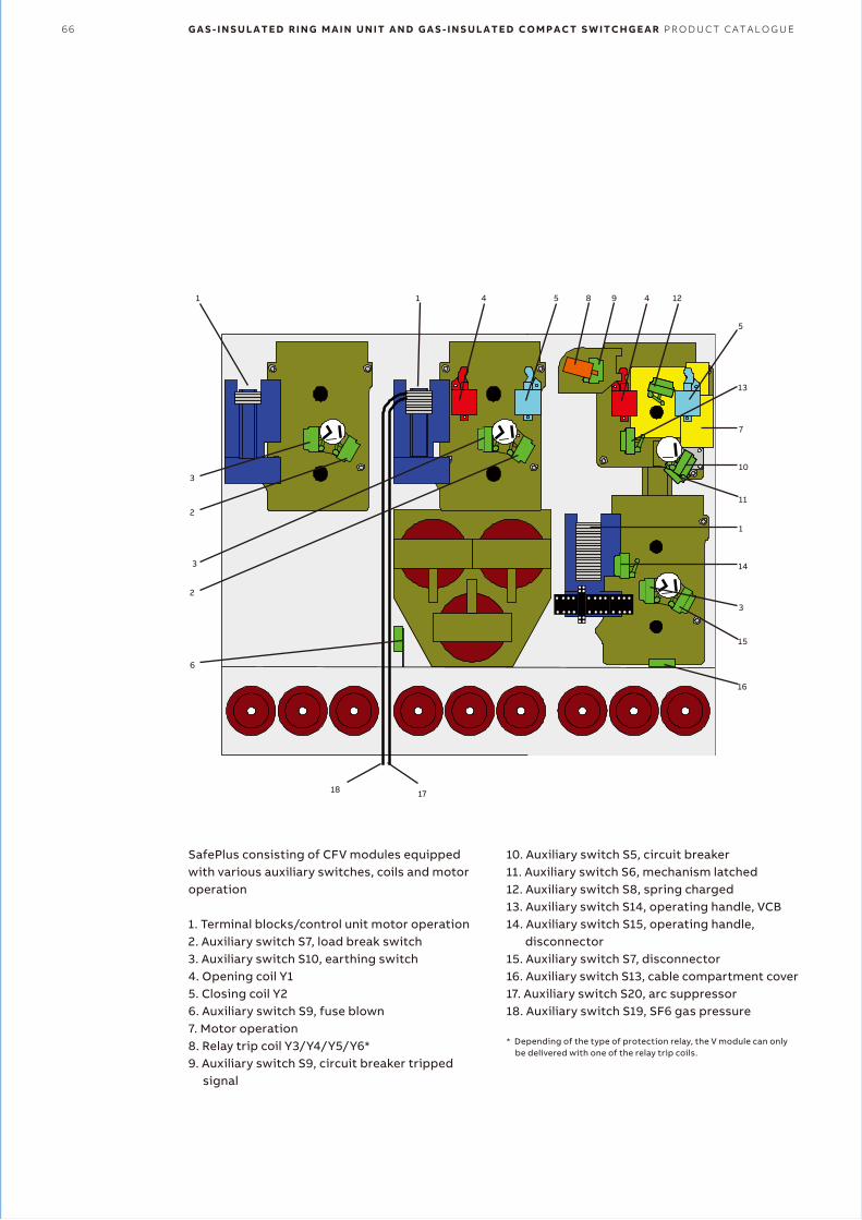
66 G A S - I N S U L A T E D R I N G M A I N U N I T A N D G A S - I N S U L A T E D C O M P A C T S W I T C H G E A R P R O D U C T C A T A L O G U E
SafePlus consisting of CFV modules equipped with various auxiliary switches, coils and motor operation
1. Terminal blocks/control unit motor operation2. Auxiliary switch S7, load break switch3. Auxiliary switch S10, earthing switch4. Opening coil Y15. Closing coil Y26. Auxiliary switch S9, fuse blown7. Motor operation8. Relay trip coil Y3/Y4/Y5/Y6*9. Auxiliary switch S9, circuit breaker tripped
signal
1
2
2
6
3
3
1 4 5
5
7
1
3
8 9 4 12
13
10
11
14
15
16
1718
10. Auxiliary switch S5, circuit breaker11. Auxiliary switch S6, mechanism latched12. Auxiliary switch S8, spring charged13. Auxiliary switch S14, operating handle, VCB14. Auxiliary switch S15, operating handle,
disconnector15. Auxiliary switch S7, disconnector16. Auxiliary switch S13, cable compartment cover17. Auxiliary switch S20, arc suppressor18. Auxiliary switch S19, SF6 gas pressure
* Depending of the type of protection relay, the V module can only be delivered with one of the relay trip coils.
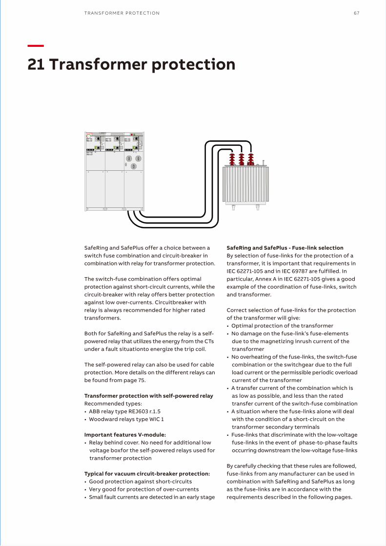
T R A N S F O R M E R P R O T E C T I O N 67
—21 Transformer protection
SafeRing and SafePlus offer a choice between a switch fuse combination and circuit-breaker in combination with relay for transformer protection.
The switch-fuse combination offers optimal protection against short-circuit currents, while the circuit-breaker with relay offers better protection against low over-currents. Circuitbreaker with relay is always recommended for higher rated transformers.
Both for SafeRing and SafePlus the relay is a self- powered relay that utilizes the energy from the CTs under a fault situationto energize the trip coil.
The self-powered relay can also be used for cable protection. More details on the different relays can be found from page 75.
Transformer protection with self-powered relayRecommended types:• ABB relay type REJ603 r.1.5• Woodward relays type WIC 1
Important features V-module:• Relay behind cover. No need for additional low
voltage boxfor the self-powered relays used for transformer protection
Typical for vacuum circuit-breaker protection:• Good protection against short-circuits• Very good for protection of over-currents• Small fault currents are detected in an early stage
SafePlus���
REF 610���
SafePlus���
REF 610���
SafePlus���
REF 610���
� �� SafeRing
SafeRing and SafePlus - Fuse-link selectionBy selection of fuse-links for the protection of a transformer, it is important that requirements in IEC 62271-105 and in IEC 69787 are fulfilled. In particular, Annex A in IEC 62271-105 gives a good example of the coordination of fuse-links, switchand transformer.
Correct selection of fuse-links for the protection of the transformer will give:• Optimal protection of the transformer• No damage on the fuse-link’s fuse-elements
due to the magnetizing inrush current of the transformer
• No overheating of the fuse-links, the switch-fuse combination or the switchgear due to the full load current or the permissible periodic overload current of the transformer
• A transfer current of the combination which is as low as possible, and less than the rated transfer current of the switch-fuse combination
• A situation where the fuse-links alone will deal with the condition of a short-circuit on the transformer secondary terminals
• Fuse-links that discriminate with the low-voltage fuse-links in the event of phase-to-phase faults occurring downstream the low-voltage fuse-links
By carefully checking that these rules are followed, fuse-links from any manufacturer can be used in combination with SafeRing and SafePlus as long as the fuse-links are in accordance with the requirements described in the following pages.
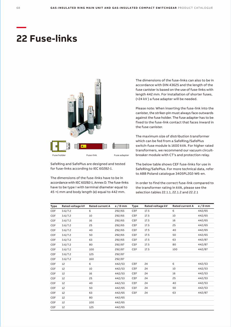
68 G A S - I N S U L A T E D R I N G M A I N U N I T A N D G A S - I N S U L A T E D C O M P A C T S W I T C H G E A R P R O D U C T C A T A L O G U E
—22 Fuse-links
SafeRing and SafePlus are designed and tested for fuse-links according to IEC 60282-1.
The dimensions of the fuse-links have to be in accordance with IEC 60282-1, Annex D. The fuse-links have to be type I with terminal diameter equal to 45 +1 mm and body length (e) equal to 442 mm.
Type
CEF
CEF
CEF
CEF
CEF
CEF
CEF
CEF
CEF
CEF
CEF
CEF
CEF
CEF
CEF
CEF
CEF
CEF
CEF
CEF
CEF
Rated voltage kV
3.6/7.2
3.6/7.2
3.6/7.2
3.6/7.2
3.6/7.2
3.6/7.2
3.6/7.2
3.6/7.2
3.6/7.2
3.6/7.2
3.6/7.2
12
12
12
12
12
12
12
12
12
12
Rated current A
6
10
16
25
40
50
63
80
100
125
160
6
10
16
25
40
50
63
80
100
125
e / D mm
292/65
292/65
292/65
292/65
292/65
292/65
292/65
292/87
292/87
292/87
292/87
442/53
442/53
442/53
442/53
442/53
442/65
442/65
442/65
442/65
442/65
Type
CEF
CEF
CEF
CEF
CEF
CEF
CEF
CEF
CEF
CEF
CEF
CEF
CEF
CEF
CEF
CEF
Rated voltage kV
17.5
17.5
17.5
17.5
17.5
17.5
17.5
17.5
17.5
24
24
24
24
24
24
24
Rated current A
6
10
16
25
40
50
63
80
100
6
10
16
25
40
50
63
e / D mm
442/65
442/65
442/65
442/65
442/65
442/65
442/87
442/87
442/87
442/53
442/53
442/53
442/53
442/53
442/53
442/87
Fuse holder Fuse adapterFuse-link
The dimensions of the fuse-links can also to be in accordance with DIN 43625 and the length of the fuse canister is based on the use of fuse-links with length 442 mm. For installation of shorter fuses, (<24 kV ) a fuse adapter will be needed.
Please note: When inserting the fuse-link into the canister, the striker-pin must always face outwards against the fuse holder. The fuse adapter has to be fixed to the fuse-link contact that faces inward in the fuse canister.
The maximum size of distribution transformer which can be fed from a SafeRing/SafePlus switch-fuse module is 1600 kVA. For higher rated transformers, we recommend our vacuum circuit- breaker module with CT’s and protection relay.
The below table shows CEF fuse-links for use in SafeRing/SafePlus. For more technical data, refer to ABB Poland catalogue 3405PL202-W6-en.
In order to find the correct fuse-link compared to the transformer rating in kVA, please see the selection tables 22.1.1, 22.1.2 and 22.2.1
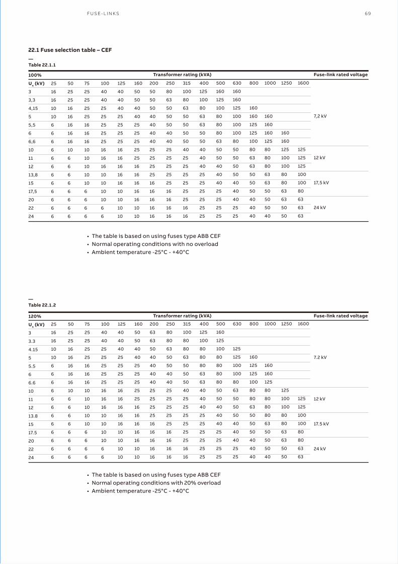
F U S E - L I N K S 69
• The table is based on using fuses type ABB CEF• Normal operating conditions with no overload• Ambient temperature -25°C - +40°C
22.1 Fuse selection table – CEF
100%
Un (kV)
3
3,3
4,15
5
5,5
6
6,6
10
11
12
13,8
15
17,5
20
22
24
25
16
16
10
10
6
6
6
6
6
6
6
6
6
6
6
6
50
25
25
16
16
16
16
16
10
6
6
6
6
6
6
6
6
75
25
25
25
25
16
16
16
10
10
10
10
10
6
6
6
6
100
40
40
25
25
25
25
25
16
16
16
10
10
10
10
6
6
125
40
40
40
25
25
25
25
16
16
16
16
16
10
10
10
10
160
50
50
40
40
25
25
25
25
25
16
16
16
16
16
10
10
200
50
50
50
40
40
40
40
25
25
25
25
16
16
16
16
16
250
80
63
50
50
50
40
40
25
25
25
25
25
16
16
16
16
315
100
80
63
50
50
50
50
40
25
25
25
25
25
25
16
16
400
125
100
80
63
63
50
50
40
40
40
25
25
25
25
25
25
500
160
125
100
80
80
80
63
50
50
40
40
40
25
25
25
25
630
160
160
125
100
100
100
80
50
50
50
50
40
40
40
25
25
800
160
160
125
125
100
80
63
63
50
50
50
40
40
40
1000
160
160
160
125
80
80
80
63
63
50
50
50
40
1250
160
160
125
100
100
80
80
63
63
50
50
1600
125
125
125
100
100
80
63
63
63
Fuse-link rated voltage
7,2 kV
12 kV
17,5 kV
24 kV
• The table is based on using fuses type ABB CEF• Normal operating conditions with 20% overload• Ambient temperature -25°C - +40°C
120%
Un (kV)
3
3.3
4.15
5
5.5
6
6.6
10
11
12
13.8
15
17.5
20
22
24
25
16
16
10
10
6
6
6
6
6
6
6
6
6
6
6
6
50
25
25
16
16
16
16
16
10
6
6
6
6
6
6
6
6
75
25
25
25
25
16
16
16
10
10
10
10
10
6
6
6
6
100
40
40
25
25
25
25
25
16
16
16
10
10
10
10
6
6
125
40
40
40
25
25
25
25
16
16
16
16
16
10
10
10
10
160
50
50
40
40
25
25
25
25
25
16
16
16
16
16
10
10
200
63
63
50
40
40
40
40
25
25
25
25
16
16
16
16
16
250
80
80
63
50
50
40
40
25
25
25
25
25
16
16
16
16
315
100
80
80
63
50
50
50
40
25
25
25
25
25
25
16
16
400
125
100
80
80
80
63
63
40
40
40
25
25
25
25
25
25
500
160
125
100
80
80
80
80
50
50
40
40
40
25
25
25
25
630
125
125
100
100
80
63
50
50
50
40
40
40
25
25
800
160
125
125
100
80
80
63
50
50
50
40
40
40
1000
160
160
125
80
80
80
80
63
50
50
50
40
1250
125
100
100
80
80
63
63
50
50
1600
125
125
100
100
80
80
63
63
Fuse-link rated voltage
7.2 kV
12 kV
17.5 kV
24 kV
—Table 22.1.1
—Table 22.1.2
Transformer rating (kVA)
Transformer rating (kVA)

70 G A S - I N S U L A T E D R I N G M A I N U N I T A N D G A S - I N S U L A T E D C O M P A C T S W I T C H G E A R P R O D U C T C A T A L O G U E
The table was calculated according to standards IEC 60787 and IEC 62271-105. The following transformer and switchgear work conditions were assumed:• Maximum long-lasting transformer overload -
120%• Magnetizing inrush current for transformers
up and including 630 kVA - 12 x In during 100 ms• Magnetizing inrush current for transformers
above 630 kVA - 10 x In during 100ms• Standard ambient working conditions for
SafeRing/SafePlus switchgear (most important: ambient temperature -25°C to +40°C)
For ratings marked with “*” transformer maximum short-circuit current at LV side, transferred to HV side, is below fuse-link minimum breaking current I3.
The table above details the rated current of a particular fuselink for a given line voltage and transformer rating. For different criteria, the fuse selection must be recalculated.
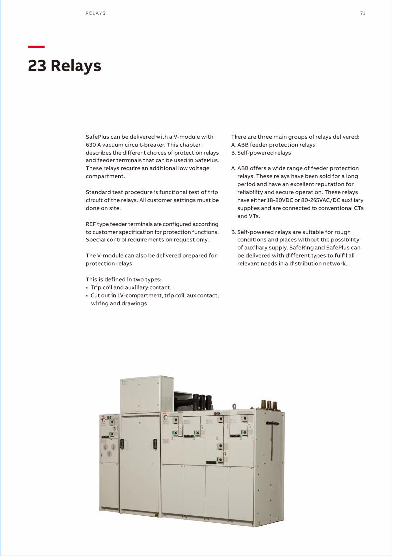
R E L A Y S 71
—23 Relays
SafePlus can be delivered with a V-module with 630 A vacuum circuit-breaker. This chapter describes the different choices of protection relays and feeder terminals that can be used in SafePlus. These relays require an additional low voltage compartment.
Standard test procedure is functional test of trip circuit of the relays. All customer settings must be done on site.
REF type feeder terminals are configured according to customer specification for protection functions. Special control requirements on request only.
The V-module can also be delivered prepared for protection relays.
This is defined in two types:• Trip coil and auxiliary contact.• Cut out in LV-compartment, trip coil, aux contact,
wiring and drawings
There are three main groups of relays delivered:A. ABB feeder protection relaysB. Self-powered relays
A. ABB offers a wide range of feeder protection relays. These relays have been sold for a long period and have an excellent reputation for reliability and secure operation. These relays have either 18-80VDC or 80-265VAC/DC auxiliary supplies and are connected to conventional CTs and VTs.
B. Self-powered relays are suitable for rough conditions and places without the possibility of auxiliary supply. SafeRing and SafePlus can be delivered with different types to fulfil all relevant needs in a distribution network.
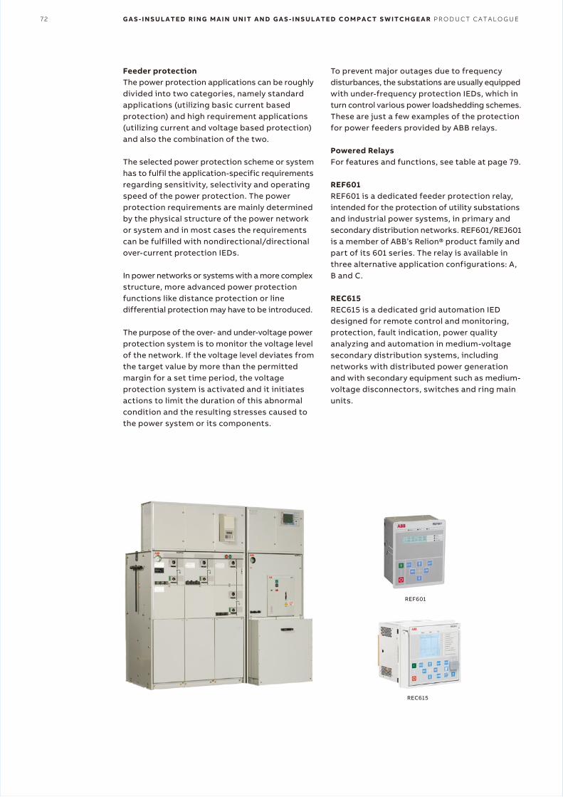
72 G A S - I N S U L A T E D R I N G M A I N U N I T A N D G A S - I N S U L A T E D C O M P A C T S W I T C H G E A R P R O D U C T C A T A L O G U E
Feeder protectionThe power protection applications can be roughly divided into two categories, namely standard applications (utilizing basic current based protection) and high requirement applications (utilizing current and voltage based protection) and also the combination of the two.
The selected power protection scheme or system has to fulfil the application-specific requirements regarding sensitivity, selectivity and operating speed of the power protection. The power protection requirements are mainly determined by the physical structure of the power network or system and in most cases the requirements can be fulfilled with nondirectional/directional over-current protection IEDs.
In power networks or systems with a more complex structure, more advanced power protection functions like distance protection or line differential protection may have to be introduced.
The purpose of the over- and under-voltage power protection system is to monitor the voltage level of the network. If the voltage level deviates from the target value by more than the permitted margin for a set time period, the voltage protection system is activated and it initiates actions to limit the duration of this abnormal condition and the resulting stresses caused to the power system or its components.
To prevent major outages due to frequency disturbances, the substations are usually equipped with under-frequency protection IEDs, which in turn control various power loadshedding schemes. These are just a few examples of the protection for power feeders provided by ABB relays.
Powered RelaysFor features and functions, see table at page 79.
REF601REF601 is a dedicated feeder protection relay, intended for the protection of utility substations and industrial power systems, in primary and secondary distribution networks. REF601/REJ601 is a member of ABB’s Relion® product family and part of its 601 series. The relay is available in three alternative application configurations: A, B and C.
REC615REC615 is a dedicated grid automation IED designed for remote control and monitoring, protection, fault indication, power quality analyzing and automation in medium-voltagesecondary distribution systems, including networks with distributed power generation and with secondary equipment such as medium- voltage disconnectors, switches and ring main units.
REF601
REC615
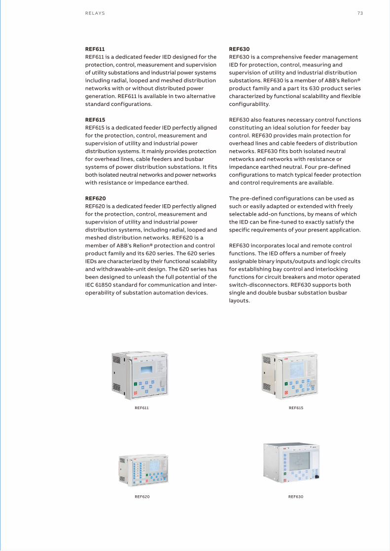
R E L A Y S 73
REF611REF611 is a dedicated feeder IED designed for the protection, control, measurement and supervision of utility substations and industrial power systems including radial, looped and meshed distribution networks with or without distributed power generation. REF611 is available in two alternative standard configurations.
REF615REF615 is a dedicated feeder IED perfectly aligned for the protection, control, measurement and supervision of utility and industrial power distribution systems. It mainly provides protection for overhead lines, cable feeders and busbar systems of power distribution substations. It fits both isolated neutral networks and power networks with resistance or impedance earthed.
REF620REF620 is a dedicated feeder IED perfectly aligned for the protection, control, measurement and supervision of utility and industrial power distribution systems, including radial, looped and meshed distribution networks. REF620 is amember of ABB’s Relion® protection and control product family and its 620 series. The 620 series IEDs are characterized by their functional scalability and withdrawable-unit design. The 620 series has been designed to unleash the full potential of the IEC 61850 standard for communication and inter- operability of substation automation devices.
REF630REF630 is a comprehensive feeder management IED for protection, control, measuring and supervision of utility and industrial distribution substations. REF630 is a member of ABB’s Relion® product family and a part its 630 product series characterized by functional scalability and flexible configurability.
REF630 also features necessary control functions constituting an ideal solution for feeder bay control. REF630 provides main protection for overhead lines and cable feeders of distributionnetworks. REF630 fits both isolated neutral networks and networks with resistance or impedance earthed neutral. Four pre-defined configurations to match typical feeder protection and control requirements are available.
The pre-defined configurations can be used as such or easily adapted or extended with freely selectable add-on functions, by means of which the IED can be fine-tuned to exactly satisfy the specific requirements of your present application.
REF630 incorporates local and remote control functions. The IED offers a number of freely assignable binary inputs/outputs and logic circuits for establishing bay control and interlocking functions for circuit breakers and motor operated switch-disconnectors. REF630 supports both single and double busbar substation busbar layouts.
REF611 REF615
REF620 REF630
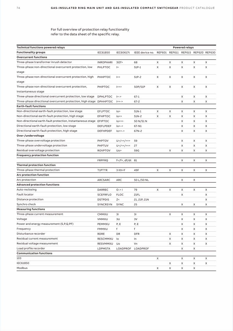
74 G A S - I N S U L A T E D R I N G M A I N U N I T A N D G A S - I N S U L A T E D C O M P A C T S W I T C H G E A R P R O D U C T C A T A L O G U E
For full overview of protection relay functionality refer to the data sheet of the specific relay.
Technical functions powered relays
Functionality groups
Overcurrent functions
Three-phase transformer inrush detector
Three-phase non-directional overcurrent protection, low
stage
Three-phase non-directional overcurrent protection, high
stage
Three-phase non-directional overcurrent protection,
instantaneous stage
Three-phase directional overcurrent protection, low stage
Three-phase directional overcurrent protection, high stage
Earth-fault functions
Non-directional earth-fault protection, low stage
Non-directional earth-fault protection, high stage
Non-directional earth-fault protection, instantaneous stage
Directional earth-fault protection, low stage
Directional earth-fault protection, high stage
Over-/undervoltage
Three-phase overvoltage protection
Three-phase undervoltage protection
Residual overvoltage protection
Frequency protection function
Thermal protection function
Three-phase thermal protection
Arc protection function
Arc protection
Advanced protection functions
Auto-reclosing
Fault locator
Distance protection
Synchro check
Measuring functions
Three-phase current measurement
Voltage
Power and energy measurement (S,P,Q,PF)
Frequency
Disturbance recorder
Residual current measurement
Residual voltage measurement
Load profile recorder
Communication functions
103
IEC61850
Modbus
IEC61850
INROPHARI
PHLPTOC
PHHPTOC
PHIPTOC
DPHLPTOC
DPHHPTOC
EFLPTOC
EFHPTOC
EFIPTOC
DEFLPDEF
DEFHPDEF
PHPTOV
PHPTUV
ROVPTOV
FRPFRQ
T1PTTR
ARCSARC
DARREC
SCEFRFLO
DSTPDIS
SYNCRSYN
CMMXU
VMMXU
PEMMXU
FMMXU
RDRE
RESCMMXU
RESVMMXU
LDPMSTA
IEC60617t
3l2f>
I>
I>>
I>>>
I>->
I>>->
Io>
Io>>
Io>>>
Io>->
Io>>->
U>/>>/>>>
U</<</<<<
Uo>
f>/f<, df/dt
3 Ith>F
ARC
O-> I
FLOC
Z<
SYNC
3I
3U
P, E
f
DR
Io
Uo
LOADPROF
IEEE device no.
68
51P-1
51P-2
50P/51P
67-1
67-2
51N-1
51N-2
50 N/51 N
67-N1
67N-2
59
27
59G
81
49F
50 L/50 NL
79
21FL
21, 21P, 21N
25
3I
3V
P, E
f
DFR
In
Vn
LOADPROF
REF601
X
X
X
X
X
X
X
X
X
X
REF611
X
X
X
X
X
X
X
X
X
X
X
X
X
X
X
REF615
X
X
X
X
X
X
X
X
X
X
X
X
X
X
X
X
X
X
X
X
X
X
X
X
X
X
X
X
X
X
X
REF620
X
X
X
X
X
X
X
X
X
X
X
X
X
X
X
X
X
X
X
X
X
X
X
X
X
X
X
X
X
X
REF630
X
X
X
X
X
X
X
X
X
X
X
X
X
X
X
X
X
X
X
X
X
X
X
X
X
X
X
X
X
Powered relays
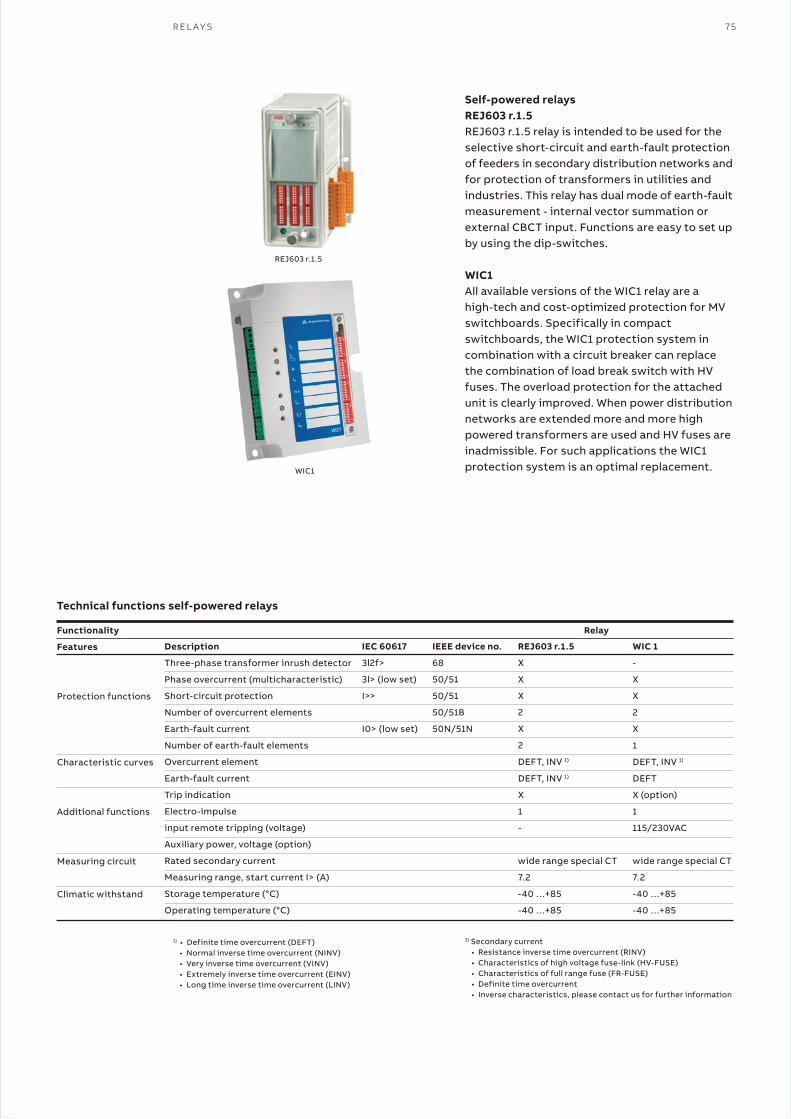
R E L A Y S 75
Self-powered relaysREJ603 r.1.5REJ603 r.1.5 relay is intended to be used for the selective short-circuit and earth-fault protection of feeders in secondary distribution networks and for protection of transformers in utilities and industries. This relay has dual mode of earth-fault measurement - internal vector summation or external CBCT input. Functions are easy to set up by using the dip-switches.
WIC1All available versions of the WIC1 relay are a high-tech and cost-optimized protection for MV switchboards. Specifically in compact switchboards, the WIC1 protection system in combination with a circuit breaker can replace the combination of load break switch with HV fuses. The overload protection for the attached unit is clearly improved. When power distributionnetworks are extended more and more high powered transformers are used and HV fuses are inadmissible. For such applications the WIC1 protection system is an optimal replacement.
Technical functions self-powered relays
1) • Definite time overcurrent (DEFT)• Normal inverse time overcurrent (NINV)• Very inverse time overcurrent (VINV)• Extremely inverse time overcurrent (EINV)• Long time inverse time overcurrent (LINV)
Functionality
Features
Protection functions
Characteristic curves
Additional functions
Measuring circuit
Climatic withstand
Description
Three-phase transformer inrush detector
Phase overcurrent (multicharacteristic)
Short-circuit protection
Number of overcurrent elements
Earth-fault current
Number of earth-fault elements
Overcurrent element
Earth-fault current
Trip indication
Electro-impulse
input remote tripping (voltage)
Auxiliary power, voltage (option)
Rated secondary current
Measuring range, start current I> (A)
Storage temperature (°C)
Operating temperature (°C)
IEC 60617
3l2f>
3l> (low set)
I>>
I0> (low set)
IEEE device no.
68
50/51
50/51
50/51B
50N/51N
REJ603 r.1.5
X
X
X
2
X
2
DEFT, INV 1)
DEFT, INV 1)
X
1
-
wide range special CT
7.2
-40 …+85
-40 …+85
WIC 1
-
X
X
2
X
1
DEFT, INV 1)
DEFT
X (option)
1
115/230VAC
wide range special CT
7.2
-40 …+85
-40 …+85
Relay
3) Secondary current• Resistance inverse time overcurrent (RINV)• Characteristics of high voltage fuse-link (HV-FUSE)• Characteristics of full range fuse (FR-FUSE)• Definite time overcurrent• Inverse characteristics, please contact us for further information
REJ603 r.1.5
WIC1

76 G A S - I N S U L A T E D R I N G M A I N U N I T A N D G A S - I N S U L A T E D C O M P A C T S W I T C H G E A R P R O D U C T C A T A L O G U E
REJ603 r.1.5 transformer protection and cable protection kit (self-powered)
Transformer type
Transformer type
Transformer type
Transformer type
Transformer type
Transformer protection and cable protection kit (self-powered)
Transformer type
Transformer type
Transformer type
Transformer type
Ring core current transformer type
CT1
CT2
CT2
CT4
CT5
Ring core current transformer type
W2
W3
W4
W5
Current range
8- 28 A
16-56 A
32-112 A
64-224 A
128-448 A
Current range
16-56 A
32-112 A
64-224 A
128-448 A
Ring core current transformers and earth-fault transformers
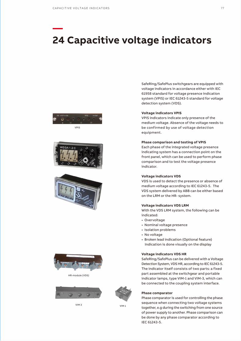
C A P A C I T I V E V O L T A G E I N D I C A T O R S 77
—24 Capacitive voltage indicators
SafeRing/SafePlus switchgears are equipped with voltage indicators in accordance either with IEC 61958 standard for voltage presence indication system (VPIS) or IEC 61243-5 standard for voltage detection system (VDS).
Voltage indicators VPISVPIS indicators indicate only presence of the medium voltage. Absence of the voltage needs to be confirmed by use of voltage detection equipment.
Phase comparison and testing of VPISEach phase of the integrated voltage presence indicating system has a connection point on the front panel, which can be used to perform phase comparison and to test the voltage presence indicator.
Voltage indicators VDSVDS is used to detect the presence or absence of medium voltage according to IEC 61243-5. The VDS system delivered by ABB can be either based on the LRM or the HR- system.
Voltage indicators VDS LRMWith the VDS LRM system, the following can be indicated:• Overvoltage• Nominal voltage presence• Isolation problems• No voltage• Broken lead indication (Optional feature)
Indication is done visually on the display
Voltage indicators VDS HRSafeRing/SafePlus can be delivered with a Voltage Detection System, VDS HR, according to IEC 61243-5.The indicator itself consists of two parts: a fixed part assembled at the switchgear and portable indicator lamps, type VIM-1 and VIM-3, which can be connected to the coupling system interface.
Phase comparatorPhase comparator is used for controlling the phase sequence when connecting two voltage systems together, e.g during the switching from one source of power supply to another. Phase comparison can be done by any phase comparator according to IEC 61243-5.
VPIS
HR-module (VDS)
VIM 3 VIM 1
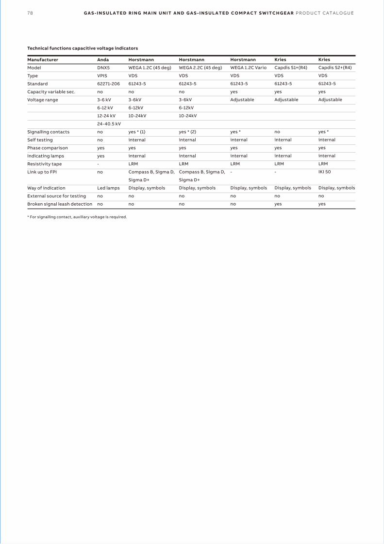
78 G A S - I N S U L A T E D R I N G M A I N U N I T A N D G A S - I N S U L A T E D C O M P A C T S W I T C H G E A R P R O D U C T C A T A L O G U E
* For signalling contact, auxiliary voltage is required.
Manufacturer
Model
Type
Standard
Capacity variable sec.
Voltage range
Signalling contacts
Self testing
Phase comparison
Indicating lamps
Resistivity tape
Link up to FPI
Way of indication
External source for testing
Broken signal leash detection
Anda
DNX5
VPIS
62271-206
no
3-6 kV
6-12 kV
12-24 kV
24-40.5 kV
no
no
yes
yes
-
no
Led lamps
no
no
Horstmann
WEGA 1.2C (45 deg)
VDS
61243-5
no
3-6kV
6-12kV
10-24kV
yes * (1)
internal
yes
internal
LRM
Compass B, Sigma D,
Sigma D+
Display, symbols
no
no
Horstmann
WEGA 2.2C (45 deg)
VDS
61243-5
no
3-6kV
6-12kV
10-24kV
yes * (2)
internal
yes
internal
LRM
Compass B, Sigma D,
Sigma D+
Display, symbols
no
no
Horstmann
WEGA 1.2C Vario
VDS
61243-5
yes
Adjustable
yes *
internal
yes
internal
LRM
-
Display, symbols
no
no
Kries
Capdis S1+(R4)
VDS
61243-5
yes
Adjustable
no
internal
yes
internal
LRM
-
Display, symbols
no
yes
Kries
Capdis S2+(R4)
VDS
61243-5
yes
Adjustable
yes *
internal
yes
internal
LRM
IKI 50
Display, symbols
no
yes
Technical functions capacitive voltage indicators
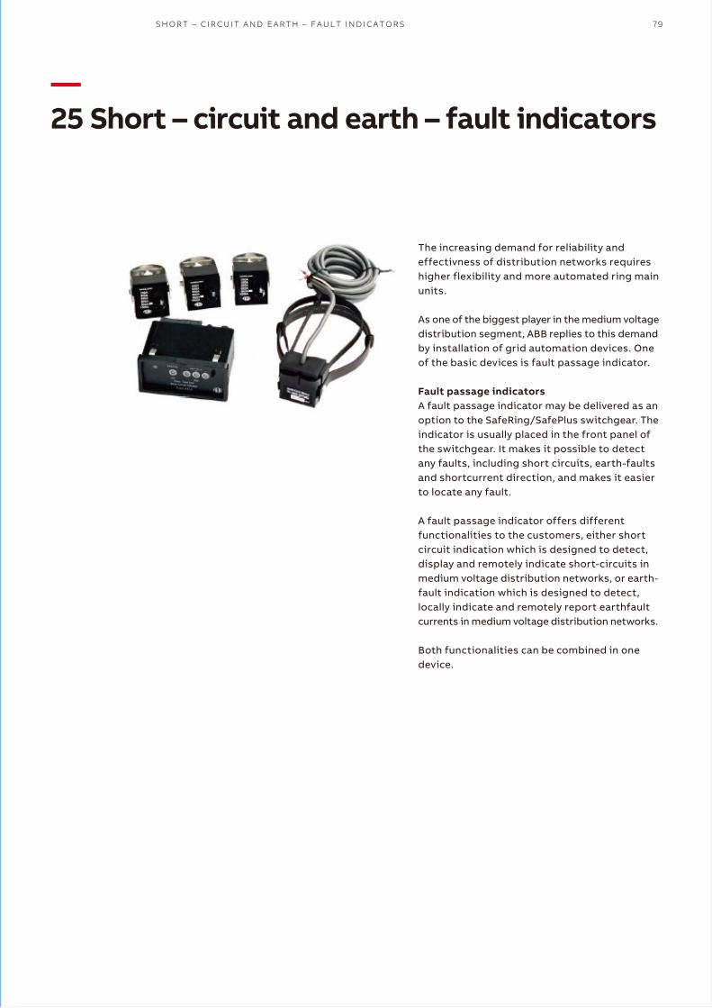
S H O R T – C I R C U I T A N D E A R T H – F A U L T I N D I C A T O R S 79
—25 Short – circuit and earth – fault indicators
The increasing demand for reliability and effectivness of distribution networks requires higher flexibility and more automated ring main units.
As one of the biggest player in the medium voltage distribution segment, ABB replies to this demand by installation of grid automation devices. One of the basic devices is fault passage indicator.
Fault passage indicatorsA fault passage indicator may be delivered as an option to the SafeRing/SafePlus switchgear. The indicator is usually placed in the front panel of the switchgear. It makes it possible to detectany faults, including short circuits, earth-faults and shortcurrent direction, and makes it easier to locate any fault.
A fault passage indicator offers different functionalities to the customers, either short circuit indication which is designed to detect, display and remotely indicate short-circuits in medium voltage distribution networks, or earth- fault indication which is designed to detect, locally indicate and remotely report earthfault currents in medium voltage distribution networks.
Both functionalities can be combined in one device.

80 G A S - I N S U L A T E D R I N G M A I N U N I T A N D G A S - I N S U L A T E D C O M P A C T S W I T C H G E A R P R O D U C T C A T A L O G U E
—26 Manometers/pressure indicators
SafeRing and SafePlus are sealed systems, designed and tested according to IEC 62271-200 as maintenance free switchgear for lifetime (30 years). The switchgear does not require any gas handling.
ABB applies state of the art technology for gas tightness providing the equipment with an expected leakage rate lower than 0.1 % per annum, referring to the filling-pressure of 1.4 bar*. The switchgear will maintain gas-tightness and a gas- pressure better than 1.35 bar* throughout its designed lifespan. This pressure value is still within a good margin from pressure used during the type tests, which is 1.3 bar*.
* at 20°C.
For increasing the safety under operation of the switchgear, manometers may be used for each tank.
In case of need of remote indication, manometers can be equipped with signalling contacts. Detailed descriptions of manometers functions are described in the table on next page.
AltitudeMax height above sea level for installation without reducing gas pressure is 1500 meters. In the interval from 1500 to 2000 meters, gas pressure has to be reduced. For installation above 2000 meters, please contact ABB for instructions.
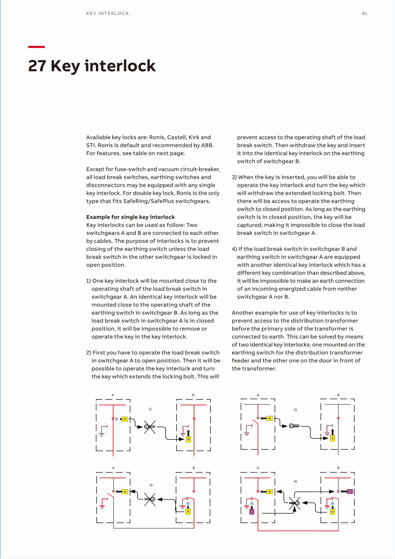
K E Y I N T E R L O C K 81
—27 Key interlock
Available key locks are: Ronis, Castell, Kirk and STI. Ronis is default and recommended by ABB. For features, see table on next page.
Except for fuse-switch and vacuum circuit-breaker, all load break switches, earthing switches and disconnectors may be equipped with any single key interlock. For double key lock, Ronis is the only type that fits SafeRing/SafePlus switchgears.
Example for single key interlockKey interlocks can be used as follow: Two switchgears A and B are connected to each other by cables. The purpose of interlocks is to prevent closing of the earthing switch unless the load break switch in the other switchgear is locked in open position.
1) One key interlock will be mounted close to the operating shaft of the load break switch in switchgear A. An identical key interlock will be mounted close to the operating shaft of the earthing switch in switchgear B. As long as the load break switch in switchgear A is in closed position, it will be impossible to remove or operate the key in the key interlock.
2) First you have to operate the load break switch in switchgear A to open position. Then it will be possible to operate the key interlock and turn the key which extends the locking bolt. This will
A B
1)
A B
2)
A B
3)
A B
4)
prevent access to the operating shaft of the load break switch. Then withdraw the key and insert it into the identical key interlock on the earthing switch of switchgear B.
3) When the key is inserted, you will be able to operate the key interlock and turn the key which will withdraw the extended locking bolt. Then there will be access to operate the earthing switch to closed position. As long as the earthing switch is in closed position, the key will be captured, making it impossible to close the load break switch in switchgear A.
4) If the load break switch in switchgear B and earthing switch in switchgear A are equipped with another identical key interlock which has a different key combination than described above, it will be impossible to make an earth connection of an incoming energized cable from neither switchgear A nor B.
Another example for use of key interlocks is to prevent access to the distribution transformer before the primary side of the transformer is connected to earth. This can be solved by means of two identical key interlocks: one mounted on the earthing switch for the distribution transformer feeder and the other one on the door in front of the transformer.
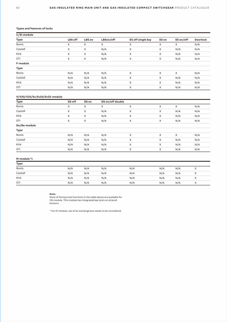
82 G A S - I N S U L A T E D R I N G M A I N U N I T A N D G A S - I N S U L A T E D C O M P A C T S W I T C H G E A R P R O D U C T C A T A L O G U E
C/Sl-module
Type
Ronis
Castell
Kirk
STI
F-module
Type
Ronis
Castell
Kirk
STI
V/V20/V25/Sv/Sv20/Sv25-module
Type
Ronis
Castell
Kirk
STI
De/Be-module
Type
Ronis
Castell
Kirk
STI
M-module *)
Type
Ronis
Castell
Kirk
STI
LBS off
X
X
X
X
N/A
N/A
N/A
N/A
DS off
X
X
X
X
N/A
N/A
N/A
N/A
N/A
N/A
N/A
N/A
LBS on
X
X
X
X
N/A
N/A
N/A
N/A
DS on
X
X
X
X
N/A
N/A
N/A
N/A
N/A
N/A
N/A
N/A
LBSon/off
X
N/A
N/A
N/A
N/A
N/A
N/A
N/A
DS on/off double
X
N/A
N/A
N/A
N/A
N/A
N/A
N/A
N/A
N/A
N/A
N/A
ES off single key
X
X
X
X
X
X
X
X
X
X
X
X
X
X
X
X
N/A
N/A
N/A
N/A
ES on
X
X
X
X
X
X
X
X
X
X
X
X
X
X
X
X
N/A
N/A
N/A
N/A
ES on/off
X
N/A
N/A
N/A
X
N/A
N/A
N/A
X
N/A
N/A
N/A
X
N/A
N/A
N/A
N/A
N/A
N/A
N/A
Doorlock
N/A
N/A
N/A
N/A
N/A
N/A
N/A
N/A
N/A
N/A
N/A
N/A
N/A
N/A
N/A
N/A
X
X
X
X
Note:None of the key lock functions in the table above are available for CB-module. This module has integrated key locks on all push buttons.
*) For M-module, use of an exchange box needs to be considered.
Types and features of locks

S M A R T G R I D A P P L I C A T I O N S 83
—28 Smart grid applications
SafeRing/SafePlus for smart grid applications12-24 kV SafeRing/SafePlus ring main unit portfolio from ABB is enhanced to meet the increasing demand for smart grid applications in secondary distribution networks.
Standard grid automation devices for ABB’s ring main units are located in the space behind the lower front cover in the Cmodules, hence eliminating the need for additional low voltage compartment on the top of the switchgear.
Thanks to the flexibility of SafeRing/SafePlus modules, grid automation solutions can also be delivered with different switchgear configurations with low voltage compartments if required.
Standard packages for smart grid applications can provide monitoring, control, measurement and supervision functionalities including feeder automation devices with wired and/or wireless communication interfaces and power supplyback-up.
The already compact SafeRing/SafePlus range can also be delivered as an ultra-compact unit with integrated Smart Grid solutions (reduced
overall height of 1’100 mm) to be fitted inside substations with height limitations.
Customer benefitsThe integrated smart grid functionalities enable the network operators to:• Monitor the grid so that they are able to remotely
locate the fault• Reconfigure the network so that the faulty part
of the network is disconnected• Reconfigure the network so that the energy loss
is minimized and/or achieve savings for future investments
Additional benefits for utilities and energy consumers are:• Improved quality of the power supply• Fewer and shorter outages and improved voltage
quality• Ensured safety for personnel• Enhanced operational efficiency and network
stability• Improved tools for the network operators and
the field crews• Less need to travel to locations with difficult
access
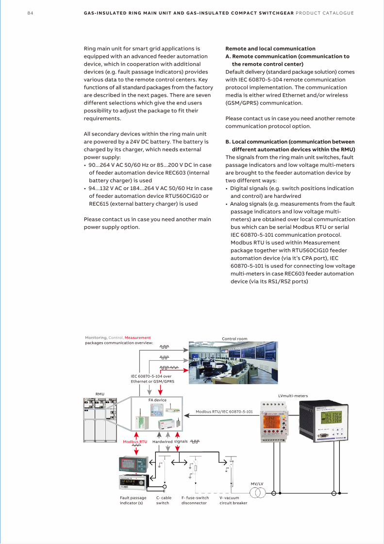
84 G A S - I N S U L A T E D R I N G M A I N U N I T A N D G A S - I N S U L A T E D C O M P A C T S W I T C H G E A R P R O D U C T C A T A L O G U E
Ring main unit for smart grid applications is equipped with an advanced feeder automation device, which in cooperation with additional devices (e.g. fault passage indicators) provides various data to the remote control centers. Key functions of all standard packages from the factory are described in the next pages. There are seven different selections which give the end users possibility to adjust the package to fit theirrequirements.
All secondary devices within the ring main unit are powered by a 24V DC battery. The battery is charged by its charger, which needs external power supply:• 90...264 V AC 50/60 Hz or 85...200 V DC in case
of feeder automation device REC603 (internal battery charger) is used
• 94...132 V AC or 184...264 V AC 50/60 Hz in case of feeder automation device RTU560CIG10 or REC615 (external battery charger) is used
Please contact us in case you need another main power supply option.
Remote and local communicationA. Remote communication (communication to
the remote control center)Default delivery (standard package solution) comes with IEC 60870-5-104 remote communication protocol implementation. The communication media is either wired Ethernet and/or wireless (GSM/GPRS) communication.
Please contact us in case you need another remote communication protocol option.
B. Local communication (communication between different automation devices within the RMU)
The signals from the ring main unit switches, fault passage indicators and low voltage multi-meters are brought to the feeder automation device by two different ways:• Digital signals (e.g. switch positions indication
and control) are hardwired• Analog signals (e.g. measurements from the fault
passage indicators and low voltage multi- meters) are obtained over local communication bus which can be serial Modbus RTU or serial IEC 60870-5-101 communication protocol. Modbus RTU is used within Measurement package together with RTU560CIG10 feeder automation device (via it’s CPA port), IEC 60870-5-101 is used for connecting low voltage multi-meters in case REC603 feeder automation device (via its RS1/RS2 ports)
Modbus RTU Hardwired
Modbus RTU/IEC 60870-5-101
LVmulti-meters
Control room
IEC 60870-5-104 overEthernet or GSM/GPRS
RMU
Monitoring, Control, Measurementpackages communication overview:
signals
MV/LV
Fault passageindicator (s)
C- cableswitch
F- fuse-switchdisconnector
V- vacuumcircuit breaker
FA device
S M A R T G R I D A P P L I C A T I O N S 85
PackagesAll standard packages include:• Power supply backup source for automation
devices (24V DC batteries and battery charger)• Wire (Ethernet) and/or wireless (GSM/GPRS)
communication interfaces (SIM card is not part of delivery)
• IEC 60870-5-104 host (slave) communication protocol Three levels of automation packages are defined below
There are additional options which can be selected for each package.
Main selections and their options are (*) default values)1. Automation level• Remote Monitoring package• Remote Control package*)
• Remote Measurement package
2. Feeder automation device• REC603 *)• RTU560CIG10
GPRS communication/modem:- No *)
- RER601- 560MDD10
• REC615GPRS communication/modem:- None *)
- RER601
3. MV network fault types• OC and EF directional• OC and EF non directional *)
• Fault
4. Fault passage indicators• Kries - IKI-50_1F (directional)• Horstmann - ComPass B (directional)• Kries - IKI-20U2 *)
• Horstmann - SIGMA F+E (AC/DC)
5. Fault passage indicators remote reset• No• Yes *)
6. Distribution transformer feeders common remote emergency trip
• No• Yes *)
7. Supervision of the LV side of the distribution transformer
• None *)
• Vamp: WIMO 6CP10• Circutor: CVM-MINI-ITF-RS485-C2
Options description1. Automation levelThe three automation levels (packages) are described below.
Remote MonitoringThis package provides remote monitoring of:• The position of load break switches in C modules
(-> grid topology supervision)• Fault passage indicator fault signalization (-> fast
fault localization, reduced outage time, efficient use of manpower)
• Faults in the transformer feeders
Remote Control This package includes the features from the Remote Monitoring package and in addition provides:• Remote control of load break switches in C
modules (-> fast fault isolation, fast restoration of healthy part of the MV network, operator safety)
Remote MeasurementThis package includes the features from the Remote Control package and in addition provides:• MV network analog data values such as:
currents, voltages, frequency, power, energy, load flow direction etc. (-> improved notification of overloaded equipment, better maintenance planning, improved power quality)
Note: There are spare inputs (1 – 5 pieces) which can be used for additional customer specified “digital/ binary” signals such as: SF6 gas pressure signal, low voltage fuses tripped signal, transformer overheating signal etc. The number of spare inputs depends on configuration of ring main unit (CCF, CCCF etc.) and on the type of fault detection for the MV network.
2. Feeder automation deviceCompact feeder automation devices secure remote monitoring and control of the secondary substations in the distribution network. It enables the network control centers to monitor and control the field devices over the different communication infrastructures.

86 G A S - I N S U L A T E D R I N G M A I N U N I T A N D G A S - I N S U L A T E D C O M P A C T S W I T C H G E A R P R O D U C T C A T A L O G U E
REC603The Wireless Controller REC603 is a compact, solution based device for the remote control and monitoring of secondary substations such as network disconnectors, load break switches and ring main units in distribution networks.
REC603 enables the network control system to monitor and control the field devices over the public communication infrastructure (GPRS). The Wireless Controller REC603 utilizes the built-in GPRS for reliable and secure end-to-end communication providing remote monitoring and control of up to three objects.
RTU560CIG10The RTU560 DIN rail provides advanced functionality and makes it the perfect fit for existing and future Grid Automation solutions. The compact housing with the possibility tointegrate hardwired information fulfills complex requirements and space restrictions at the same time.
3. MV network fault typesDifferent signals from Fault Passage Indicators can be transmitted to the control centers. These are selected based on type of the MV network (isolated neutral, compensated neutral, high resistance earthing, low resistance earthing orsolidly earthing).
Available options are:OC and EF directionalWith this selection, two different types of events can be transferred to the remote control centers:• Fault in forward direction (does not differentiate
overcurrent and earth-fault)• Fault in backward direction (does not differentiate
overcurrent and earth-fault)
OC and EF non directionalWith this selection, two different types of events can be transferred to the remote control centers:• Over-current fault (does not differentiate fault
direction)• Earth-fault (does not differentiate fault direction)
FaultWith this selection, one type of event can be transferred to the remote control centers:• Fault (does not differentiate overcurrent and
earth-fault nor fault direction)
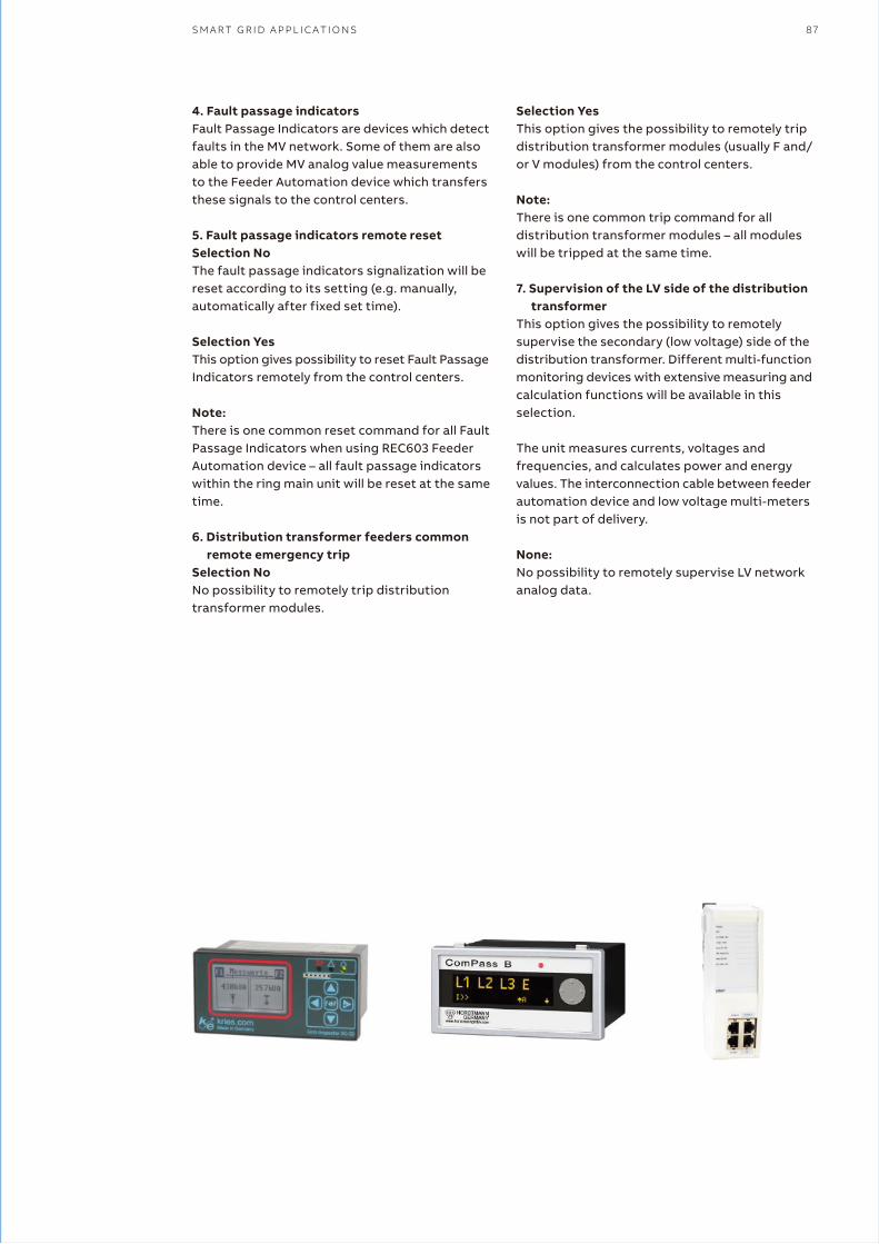
S M A R T G R I D A P P L I C A T I O N S 87
4. Fault passage indicatorsFault Passage Indicators are devices which detect faults in the MV network. Some of them are also able to provide MV analog value measurements to the Feeder Automation device which transfers these signals to the control centers.
5. Fault passage indicators remote resetSelection NoThe fault passage indicators signalization will be reset according to its setting (e.g. manually, automatically after fixed set time).
Selection YesThis option gives possibility to reset Fault Passage Indicators remotely from the control centers.
Note: There is one common reset command for all Fault Passage Indicators when using REC603 Feeder Automation device – all fault passage indicators within the ring main unit will be reset at the same time.
6. Distribution transformer feeders common remote emergency trip
Selection NoNo possibility to remotely trip distribution transformer modules.
Selection YesThis option gives the possibility to remotely trip distribution transformer modules (usually F and/ or V modules) from the control centers.
Note: There is one common trip command for all distribution transformer modules – all modules will be tripped at the same time.
7. Supervision of the LV side of the distribution transformer
This option gives the possibility to remotely supervise the secondary (low voltage) side of the distribution transformer. Different multi-function monitoring devices with extensive measuring and calculation functions will be available in this selection.
The unit measures currents, voltages and frequencies, and calculates power and energy values. The interconnection cable between feeder automation device and low voltage multi-meters is not part of delivery.
None:No possibility to remotely supervise LV network analog data.
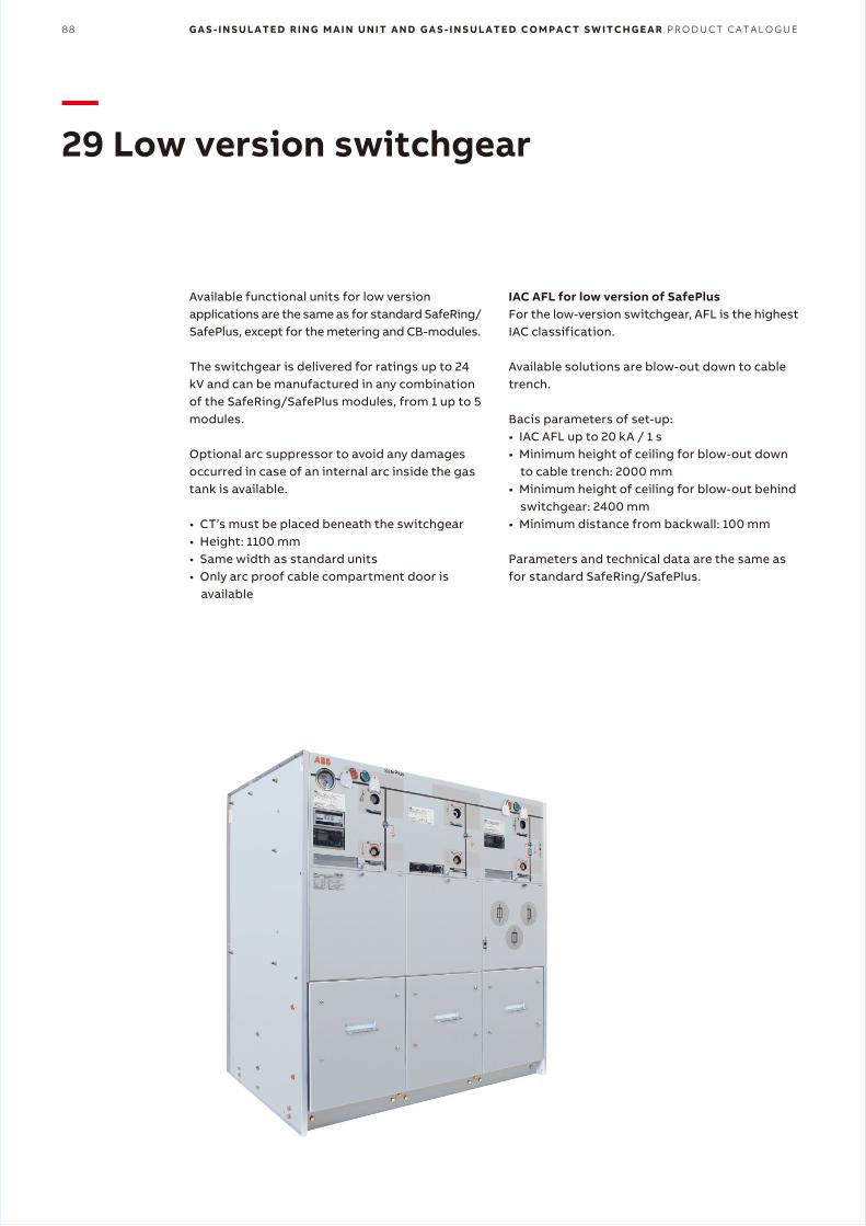
88 G A S - I N S U L A T E D R I N G M A I N U N I T A N D G A S - I N S U L A T E D C O M P A C T S W I T C H G E A R P R O D U C T C A T A L O G U E
—29 Low version switchgear
Available functional units for low version applications are the same as for standard SafeRing/ SafePlus, except for the metering and CB-modules.
The switchgear is delivered for ratings up to 24 kV and can be manufactured in any combination of the SafeRing/SafePlus modules, from 1 up to 5 modules.
Optional arc suppressor to avoid any damages occurred in case of an internal arc inside the gas tank is available.
• CT’s must be placed beneath the switchgear• Height: 1100 mm• Same width as standard units• Only arc proof cable compartment door is
available
IAC AFL for low version of SafePlusFor the low-version switchgear, AFL is the highest IAC classification.
Available solutions are blow-out down to cable trench.
Bacis parameters of set-up:• IAC AFL up to 20 kA / 1 s• Minimum height of ceiling for blow-out down
to cable trench: 2000 mm• Minimum height of ceiling for blow-out behind
switchgear: 2400 mm• Minimum distance from backwall: 100 mm
Parameters and technical data are the same as for standard SafeRing/SafePlus.
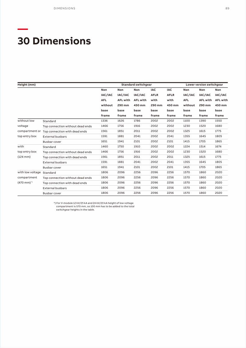
D I M E N S I O N S 89
—30 Dimensions
Height (mm)
without low
voltage
compartment or
top entry box
with
top entry box
(124 mm)
with low voltage
compartment
(470 mm) *)
Standard
Top connection without dead ends
Top connection with dead ends
External busbars
Busbar cover
Standard
Top connection without dead ends
Top connection with dead ends
External busbars
Busbar cover
Standard
Top connection without dead ends
Top connection with dead ends
External busbars
Busbar cover
Non
IAC/IAC
AFL
without
base
frame
1336
1466
1561
1591
1651
1460
1466
1561
1591
1651
1806
1806
1806
1806
1806
Non
IAC/IAC
AFL with
290 mm
base
frame
1626
1756
1851
1881
1941
1750
1756
1851
1881
1941
2096
2096
2096
2096
2096
Non
IAC/IAC
AFL with
450 mm
base
frame
1786
1916
2011
2041
2101
1910
1916
2011
2041
2101
2256
2256
2256
2256
2256
IAC
AFLR
with
290 mm
base
frame
2002
2002
2002
2002
2002
2002
2002
2002
2002
2002
2096
2096
2096
2096
2096
IAC
AFLR
with
450 mm
base
frame
2002
2002
2002
2041
2101
2002
2002
2011
2041
2101
2256
2256
2256
2256
2256
Non
IAC/IAC
AFL
without
base
frame
1100
1230
1325
1355
1415
1224
1230
1325
1355
1415
1570
1570
1570
1570
1570
Non
IAC/IAC
AFL with
290 mm
base
frame
1390
1520
1615
1645
1705
1514
1520
1615
1645
1705
1860
1860
1860
1860
1860
Non
IAC/IAC
AFL with
450 mm
base
frame
1550
1680
1775
1805
1865
1674
1680
1775
1805
1865
2020
2020
2020
2020
2020
*) For V-module 12 kV/25 kA and 24 kV/20 kA height of low voltage compartment is 570 mm, so 100 mm has to be added to the total switchgear heights in the table.
Standard switchgear Lower version switchgear
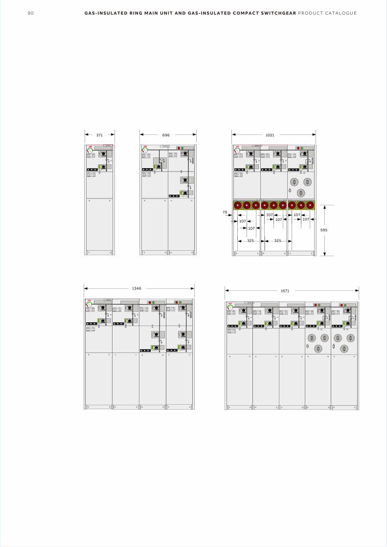
90 G A S - I N S U L A T E D R I N G M A I N U N I T A N D G A S - I N S U L A T E D C O M P A C T S W I T C H G E A R P R O D U C T C A T A L O G U E
SafePlusSafeRing
SafeRing
SafePlus
696371
13461671
SafeRing
1021
595
107
107
325 325
79107
107107
107
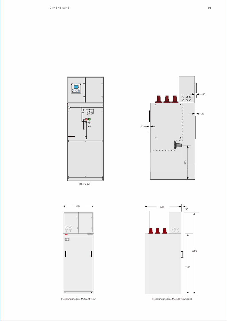
D I M E N S I O N S 91
SafePlus
69656
1336
1806
802
Metering module M, front view Metering module M, side view right
CB modul
30
20
20
595
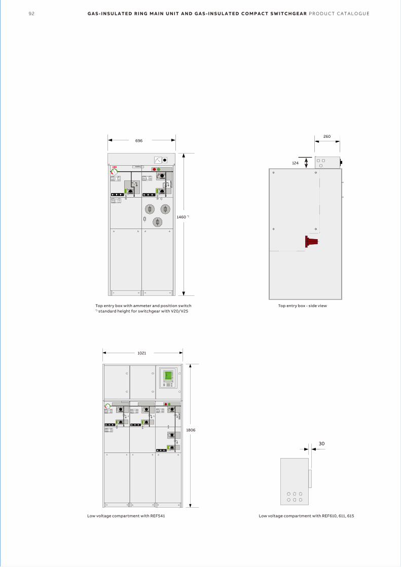
92 G A S - I N S U L A T E D R I N G M A I N U N I T A N D G A S - I N S U L A T E D C O M P A C T S W I T C H G E A R P R O D U C T C A T A L O G U E
SafeRing
1460 *)
696
124
260
1021
1806
30
Low voltage compartment with REF541 Low voltage compartment with REF610, 611, 615
Top entry box with ammeter and position switch*) standard height for switchgear with V20/V25
Top entry box - side view
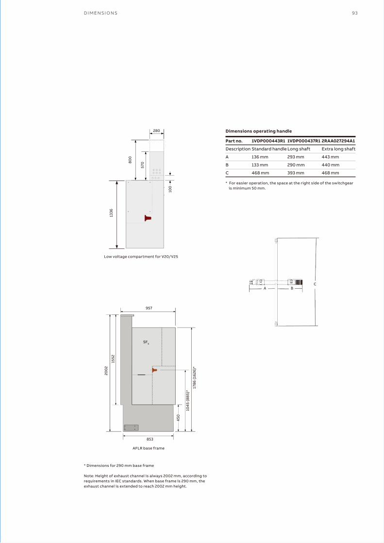
D I M E N S I O N S 93
* Dimensions for 290 mm base frame
Note: Height of exhaust channel is always 2002 mm, according to requirements in IEC standards. When base frame is 290 mm, the exhaust channel is extended to reach 2002 mm height.
Part no.
Description
A
B
C
1VDP000443R1
Standard handle
136 mm
133 mm
468 mm
1VDP000437R1
Long shaft
293 mm
290 mm
393 mm
2RAA027294A1
Extra long shaft
443 mm
440 mm
468 mm
1336
Low voltage compartment for V20/V25
28080
0
570
100
A BC
957
SF6
200
2
1552
1786
(162
6)*
1045
(885
)*
450
853
AFLR base frame
Dimensions operating handle
* For easier operation, the space at the right side of the switchgear is minimum 50 mm.
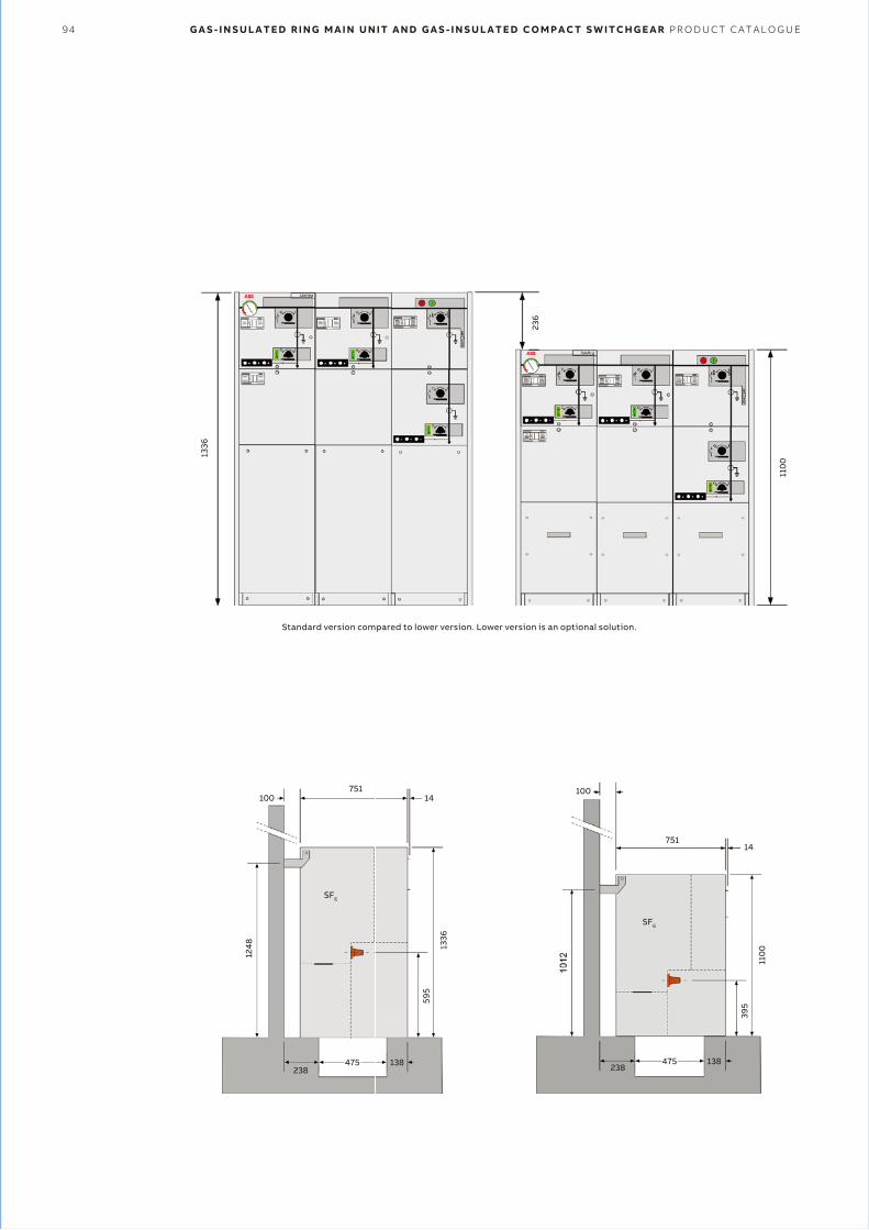
94 G A S - I N S U L A T E D R I N G M A I N U N I T A N D G A S - I N S U L A T E D C O M P A C T S W I T C H G E A R P R O D U C T C A T A L O G U E
Standard version compared to lower version. Lower version is an optional solution.
110
0751
75114
110
0
395
1248 13
36
475238
138 475238
138
595
100100
14
SF6
SF6
236
1336
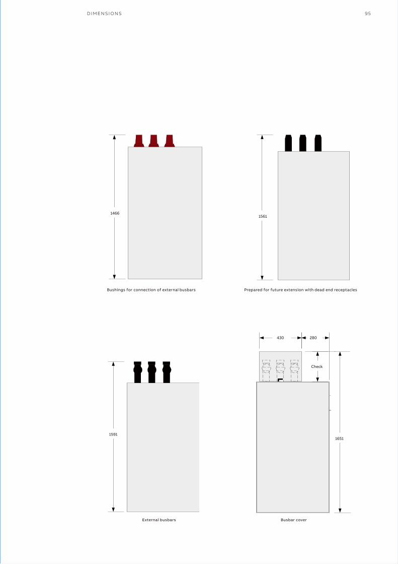
D I M E N S I O N S 95
14661561
15911651
430 280
Check
External busbars Busbar cover
Bushings for connection of external busbars Prepared for future extension with dead end receptacles
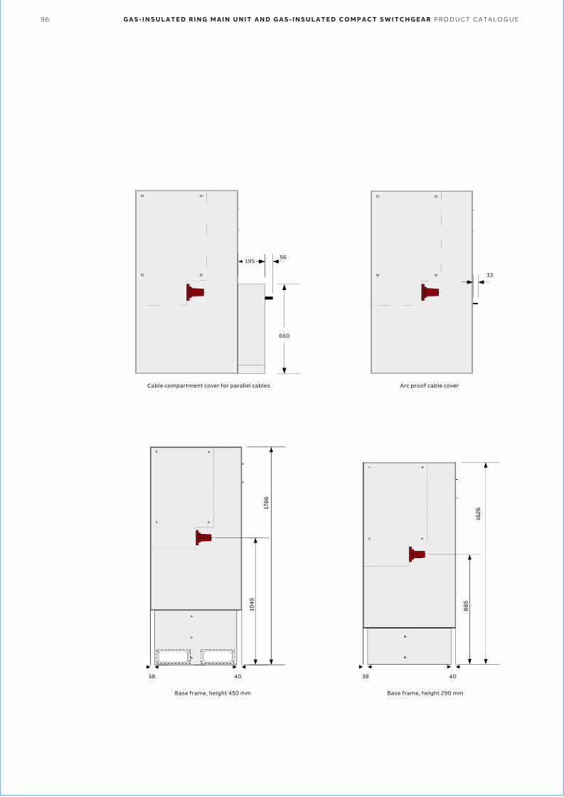
96 G A S - I N S U L A T E D R I N G M A I N U N I T A N D G A S - I N S U L A T E D C O M P A C T S W I T C H G E A R P R O D U C T C A T A L O G U E
56
660
195
4038
178
6
104
5
4038
1626
88
5
33
Base frame, height 450 mm Base frame, height 290 mm
Cable compartment cover for parallel cables Arc proof cable cover

T E C H N I C A L D A T A 97
—31 Technical data
IEC 62271-1
IEC 62271-100
IEC 62271-102
IEC 62271-105
IEC 62271-200
IEC 62271-103
IEC 60529
Common specifications for high-voltage switchgear and controlgear standards
High-voltage switchgear and controlgear-Part 100: high-voltage alternating-current circuit-breakers
High-voltage switchgear and controlgear-Part 102: alternating current disconnectors and earthing switches
High-voltage switchgear and controlgear-Part 105: alternating current switch-fuse combinations
High-voltage switchgear and controlgear-Part 200: A.C. metal-enclosed switchgear and controlgear for
rated voltages above 1 kV and up to and including 52 kV
High-voltage switches-Part 1: switches for rated voltages above 1 kV and less than 52 kV
Degrees of protection provided by enclosures (IP code)
Voltage detection system (VDS)
Voltage presence indication systems (VPIS)
Bushings
Electronic protection relays
Instrument transformers-general requirements
Current instrument transformers
Voltage instrument transformers
Current sensors
Voltage sensors
Combined bushings sensors
MV fuses
Cable connection
IEC 61243-5
IEC 62271-206, IEC 61958
CENELEC EN 50180 / EN 50181, IEC 61243-5, IEC 62271-206, IEC 60137,
EDF HN 52-S-61
IEC 60255
IEC 61869-1
IEC 61869-2
IEC 61869-3
IEC 60044-8
IEC 60044-7
IEC 60044-7, IEC 60044-8, CENELEC EN 50181, IEC 62271-206,
IEC 61243-5
IEC 60282-1
CENELEC EN 50180, CENELEC EN 50181, IEC 60137, IEC 60502-4
Codes and standardsSafeRing and SafePlus are manufactured and tested in accordance with the latest version of the below IEC regulations.
��� SafePlus
��� REF541
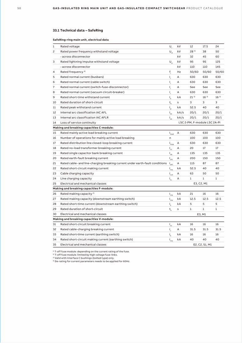
98 G A S - I N S U L A T E D R I N G M A I N U N I T A N D G A S - I N S U L A T E D C O M P A C T S W I T C H G E A R P R O D U C T C A T A L O G U E
33.1 Technical data – SafeRing
1
2
3
4
5
6
7
8
9
10
11
12
13
14
15
16
17
18
19
20
21
22
23
24
25
26
27
28
29
30
31
32
33
34
35
Rated voltage
Rated power frequency withstand voltage
- across disconnector
Rated lightning impulse withstand voltage
- across disconnector
Rated frequency 4)
Rated normal current (busbars)
Rated normal current (cable switch)
Rated normal current (switch-fuse-disconnector)
Rated normal current (vacuum circuit-breaker)
Rated short-time withstand current
Rated duration of short-circuit
Rated peak withstand current
Internal arc classification IAC AFL
Internal arc classification IAC AFLR
Loss of service continuity
Rated mainly active load breaking current
Number of operations for mainly active load breaking
Rated distribution line closed-loop breaking current
Rated no-load transformer breaking current
Rated single capacitor bank breaking current
Rated earth-fault breaking current
Rated cable- and line-charging breaking current under earth-fault conditions
Rated short-circuit making current
Cable charging capacity
Line charging capacity
Electrical and mechanical classes
Rated making capacity 2)
Rated making capacity (downstream earthing switch)
Rated short-time current (downstream earthing switch)
Rated duration of short-circuit
Electrical and mechanical classes
Rated short-circuit breaking current
Rated cable-charging breaking current
Rated short-time current (earthing switch)
Rated short-circuit making current (earthing switch)
Electrical and mechanical classes
Ur
Ud
Up
fr
Ir
Ir
Ir
Ir
Ik
tk
Ip
Iac
Iac
Iload
n
Iloop
Icc
Isb
Ief1
Ief2
Ima
Icc2
IIc
Ima
Ima
Ik
tk
Isc
Ic
Ik
Ima
kV
kV
kV
kV
kV
Hz
A
A
A
A
kA
s
kA
kA/s
kA/s
A
A
A
A
A
A
kA
A
A
kA
kA
kA
s
kA
A
kA
kA
12
28 4)
32
95
110
50/60
630
630
See
630
21 3)
3
52.5
20/1
20/1
630
100
630
20
135
200
115
52.5
63
1
21
12.5
5
1
16
31.5
16
40
17.5
38
45
95
110
50/60
630
630
See
630
16 3)
3
40
20/1
20/1
630
100
630
17
135
150
87
40
50
1
16
12.5
5
1
16
31.5
16
40
24
50
60
125
145
50/60
630
630
See
630
16 3)
3
40
20/1
20/1
630
100
630
17
135
150
87
40
50
1
16
12.5
5
1
16
31.5
16
40
LSC 2-PM, F-module LSC 2A-PI
E3, C2, M1
E3, M1
E2, C2, S1, M1
1) T-off fuse module: depending on the current rating of the fuse.2) T-off fuse module: limited by high voltage fuse-links.3) Valid with Interface C bushings (bolted type) only.4) De-rating for current parameters needs to be applied for 60Hz.
SafeRing-ring main unit, electrical data
Making and breaking capacities C-module:
Making and breaking capacities F-module:
Making and breaking capacities V-module:

T E C H N I C A L D A T A 99
33.2 Technical data – SafePlus
1
2
3
4
5
6
7
8
9
10
11
12
13
14
15
16
17
18
19
20
21
22
23
24
25
26
27
28
29
30
31
32
33
34
35
36
37
38
39
40
41
42
43
44
45
46
47
48
Rated voltage
Rated power frequency withstand voltage
- across disconnector
Rated lightning impulse withstand voltage
- across disconnector
Rated frequency 7)
Rated normal current (busbars)
Rated normal current (external busbars)
Rated normal current (cable switch)
Rated normal current (switch-fuse-disconnector) 1)
Rated normal current (vacuum circuit-breaker) 3)
Rated short-time withstand current 3) 6)
Rated duration of short-circuit
Rated peak withstand current
Internal arc classification IAC AFL
Internal arc classification IAC AFLR
Loss of service continuity
Rated mainly active load breaking current
Number of operations for mainly active load breaking
Rated distribution line closed-loop breaking current
Rated no-load transformer breaking current
Rated single capacitor bank breaking current
Rated earth-fault breaking current
Rated cable- and line-charging breaking current under earth-fault conditions
Rated short-circuit making current
Cable charging capacity
Line charging capacity
Electrical and mechanical classes
Rated making capacity 2)
Rated making capacity (downstream earthing switch)
Rated short-time current (downstream earthing switch)
Rated duration of short-circuit
Electrical and mechanical classes
Rated mainly active load breaking current 3)
Rated short-circuit breaking current
Rated cable-charging breaking current
Rated short-time current (earthing switch)
Rated short-circuit making current (earthing switch)
Electrical and mechanical classes
Rated mainly active load breaking current 3)
Rated short-circuit breaking current
Making capacity load break switch
Rated short-time current (earthing switch)
Rated short-circuit making current (earthing switch)
Electrical and mechanical classes
Rated mainly active load breaking current 3)
Rated short-circuit breaking current
Making capacity
Rated short-time current
Electrical and mechanical classes
Ur
Ud
Up
fr
Ir
Ir
Ir
Ir
Ir
Ik
tk
Ip
Iac
Iac
Iload
n
Iloop
Icc
Isc
Ief1
Ief2
Ima
Icc2
IIc
Ima
Ima
Ik
tk
I1
Isc
Ic
Ik
Ima
I1
Isc
Ima
Ik
Ima
I1
Isc
Ima
Ik
kV
kV
kV
kV
kV
Hz
A
A
A
A
A
kA
s
kA
kA/s
kA/s
A
A
A
A
A
A
kA
A
A
kA
kA
kA
s
A
kA
A
kA
kA
A
kA
kA
kA
kA
A
kA
kA
kA
12
28
32
95
110
50/60
630
1250
630
200
630
25
3
62.5
20/1
20/1
630
100
630
20
135
200
115
62.5
63
1
25
12.5
5
1
630
21
31.5
21
52.5
630
25
62.5
25
62.5
630/1250
25
62.5
25
17.5
38
45
95
110
50/60
630
1250
630
200
630
21
3
52.5
20/1
20/1
630
100
630
20
135
150
87
52.5
50
1
25
12.5
5
1
630
16
31.5
16
40
630
25
62.5
21
52.5
630/1250
20
50
20
24
50
60
125
145
50/60
630
1250
630
200
630
21
3
52.5
20/1
20/1
630
100
630
20
135
150
87
52.5
50
1
25
12.5
5
1
630
16
31.5
16
40
630
20
50
21
52.5
630/1250
20
50
20
E2, C2, M2
E2, C2, S1, M1
E2, C2, S1, M1
E3, M1
E3, C2, M1
LSC 2-PM, F-Module LSC 2A-PI, M-module LSC 2B-PM 9)
SafePlus - Compact Switchgear, electrical data
Making and breaking capacities C-module:
Making and breaking capacities F-module:
Making and breaking capacities V-module:
Making and breaking capacities V20-, V25-module:
Making and breaking capacities CB-module:
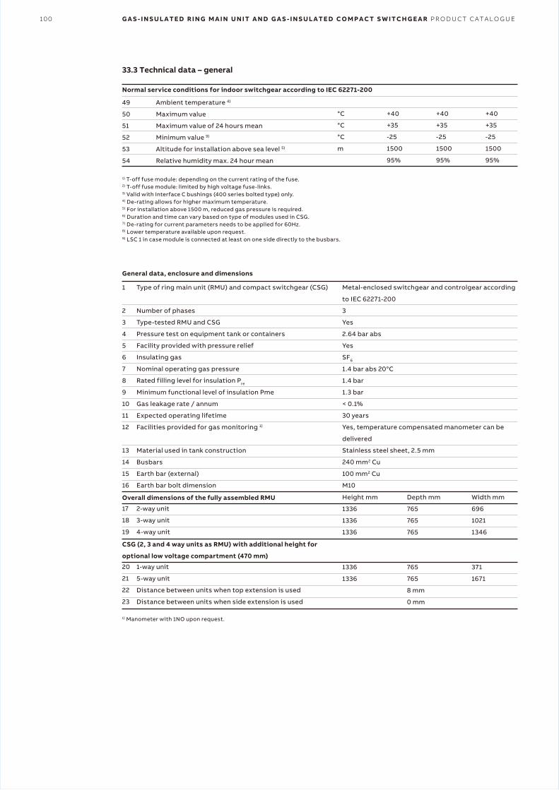
100 G A S - I N S U L A T E D R I N G M A I N U N I T A N D G A S - I N S U L A T E D C O M P A C T S W I T C H G E A R P R O D U C T C A T A L O G U E
33.3 Technical data – general
49
50
51
52
53
54
°C
°C
°C
m
+40
+35
-25
1500
95%
+40
+35
-25
1500
95%
+40
+35
-25
1500
95%
Ambient temperature 4)
Maximum value
Maximum value of 24 hours mean
Minimum value 9)
Altitude for installation above sea level 5)
Relative humidity max. 24 hour mean
1
2
3
4
5
6
7
8
9
10
11
12
13
14
15
16
17
18
19
20
21
22
23
Type of ring main unit (RMU) and compact switchgear (CSG)
Number of phases
Type-tested RMU and CSG
Pressure test on equipment tank or containers
Facility provided with pressure relief
Insulating gas
Nominal operating gas pressure
Rated filling level for insulation Pre
Minimum functional level of insulation Pme
Gas leakage rate / annum
Expected operating lifetime
Facilities provided for gas monitoring 1)
Material used in tank construction
Busbars
Earth bar (external)
Earth bar bolt dimension
2-way unit
3-way unit
4-way unit
1-way unit
5-way unit
Distance between units when top extension is used
Distance between units when side extension is used
Metal-enclosed switchgear and controlgear according
to IEC 62271-200
3
Yes
2.64 bar abs
Yes
SF6
1.4 bar abs 20°C
1.4 bar
1.3 bar
< 0.1%
30 years
Yes, temperature compensated manometer can be
delivered
Stainless steel sheet, 2.5 mm
240 mm2 Cu
100 mm2 Cu
M10
Height mm
1336
1336
1336
1336
1336
1) T-off fuse module: depending on the current rating of the fuse.2) T-off fuse module: limited by high voltage fuse-links.3) Valid with Interface C bushings (400 series bolted type) only.4) De-rating allows for higher maximum temperature.5) For installation above 1500 m, reduced gas pressure is required.6) Duration and time can vary based on type of modules used in CSG.7) De-rating for current parameters needs to be applied for 60Hz.8) Lower temperature available upon request.9) LSC 1 in case module is connected at least on one side directly to the busbars.
1) Manometer with 1NO upon request.
Depth mm
765
765
765
765
765
8 mm
0 mm
Width mm
696
1021
1346
371
1671
Normal service conditions for indoor switchgear according to IEC 62271-200
General data, enclosure and dimensions
Overall dimensions of the fully assembled RMU
CSG (2, 3 and 4 way units as RMU) with additional height for
optional low voltage compartment (470 mm)
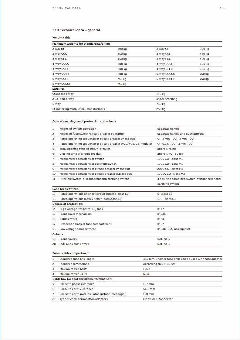
T E C H N I C A L D A T A 101
33.3 Technical data – general
Maximum weights for standard SafeRing
2-way DF
3-way CCC
3-way CFC
4-way CCCC
4-way CCFF
4-way CCVV
5-way CCFFF
5-way CCCCF
SafePlus
Standard 1-way
2-, 3- and 4-way
5-way
M-metering module incl. transformers
300 kg
450 kg
450 kg
600 kg
600 kg
600 kg
750 kg
750 kg
2-way CF
3-way CCF
3-way FCC
4-way CCCF
4-way CFFC
5-way CCCCC
5-way CCCFF
150 kg
as for SafeRing
750 kg
250 kg
300 kg
450 kg
450 kg
600 kg
600 kg
750 kg
750 kg
1
2
3
4
5
6
7
8
9
10
11
12
13
14
15
16
17
18
19
20
Means of switch operation
Means of fuse switch/circuit-breaker operation
Rated operating sequence of circuit-breaker (V-module)
Rated operating sequence of circuit-breaker (V20/V25, CB-module)
Total opening time of circuit-breaker
Closing time of circuit-breaker
Mechanical operations of switch
Mechanical operations of earthing switch
Mechanical operations of circuit-breaker (V-module)
Mechanical operations of circuit-breaker (CB-module)
Principle switch-disconnector and earthing switch
Rated operations on short circuit current (class E3)
Rated operations mainly active load (class E3)
High voltage live parts, SF6 tank
Front cover mechanism
Cable covers
Protection class of fuse compartment
Low voltage compartment
Front covers
Side and cable covers
1
2
3
4
5
6
7
8
Standard fuse-link length
Standard dimensions
Maximum size 12 kV
Maximum size 24 kV
Phase to phase clearance
Phase to earth clearance
Phase to earth over insulator surface (creepage)
Type of cable termination adapters
separate handle
separate handle and push buttons
O – 3 min – CO – 3 min – CO
O – 0,3 s – CO – 3 min – CO
approx. 75 ms
approx. 40 – 60 ms
1000 CO - class M1
1000 CO - class M1
2000 CO - class M1
10000 CO - class M3
3 position combined switch-disconnector and
earthing switch
5 - class E3
100 - class E3
IP 67
IP 2XC
IP 3X
IP 67
IP 2XC (IP22 on request)
RAL 7035
RAL 7035
442 mm. Shorter fuse-links can be used with fuse adapter
According to DIN 43625
125 A
63 A
107 mm
54.5 mm
120 mm
Elbow or T-connector
Weight table
Operations, degree of protection and colours
Fuses, cable compartment
Load break switch:
Degree of protection:
Colours:
Cable box for heat shrinkable termination:
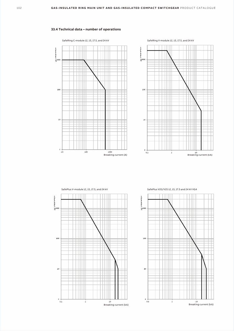
102 G A S - I N S U L A T E D R I N G M A I N U N I T A N D G A S - I N S U L A T E D C O M P A C T S W I T C H G E A R P R O D U C T C A T A L O G U E
33.4 Technical data – number of operations
SafePlus V20/V25 12, 15, 17.5 and 24 kV VG4
SafeRing C-module 12, 15, 17.5, and 24 kV SafeRing V-module 12, 15, 17.5, and 24 kV
SafePlus V-module 12, 15, 17.5, and 24 kV
Breaking current (A)
Breaking current (kA) Breaking current (kA)
Breaking current (kA)
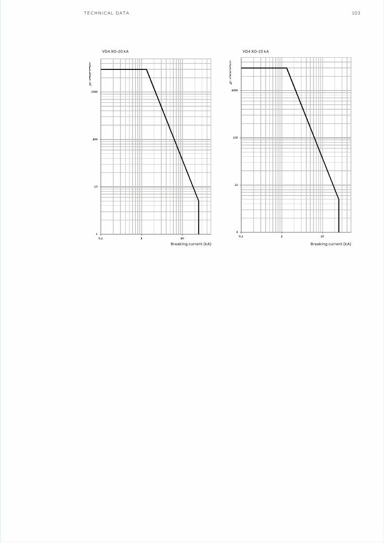
T E C H N I C A L D A T A 103
VD4 XO-20 kA VD4 XO-25 kA
Breaking current (kA) Breaking current (kA)
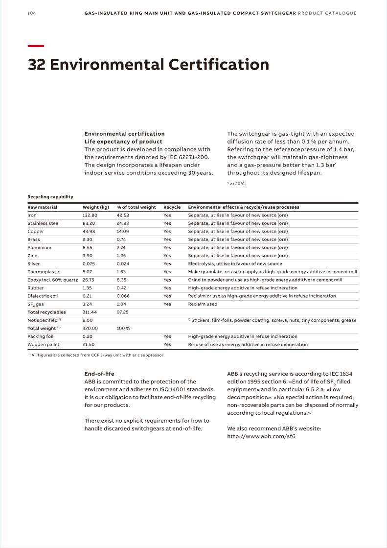
104 G A S - I N S U L A T E D R I N G M A I N U N I T A N D G A S - I N S U L A T E D C O M P A C T S W I T C H G E A R P R O D U C T C A T A L O G U E
—32 Environmental Certification
Environmental certificationLife expectancy of productThe product is developed in compliance with the requirements denoted by IEC 62271-200. The design incorporates a lifespan under indoor service conditions exceeding 30 years.
The switchgear is gas-tight with an expected diffusion rate of less than 0.1 % per annum. Referring to the referencepressure of 1.4 bar, the switchgear will maintain gas-tightness and a gas-pressure better than 1.3 bar* throughout its designed lifespan.
*) at 20°C.
End-of-lifeABB is committed to the protection of the environment and adheres to ISO 14001 standards. It is our obligation to facilitate end-of-life recycling for our products.
There exist no explicit requirements for how to handle discarded switchgears at end-of-life.
ABB’s recycling service is according to IEC 1634 edition 1995 section 6: «End of life of SF6 filled equipment» and in particular 6.5.2.a: «Low decomposition»: «No special action is required; non-recoverable parts can be disposed of normally according to local regulations.»
We also recommend ABB’s website: http://www.abb.com/sf6
**) All figures are collected from CCF 3-way unit with ar c suppressor.
Raw material
Iron
Stainless steel
Copper
Brass
Aluminium
Zinc
Silver
Thermoplastic
Epoxy incl. 60% quartz
Rubber
Dielectric coil
SF6 gas
Total recyclables
Not specified *)
Total weight **)
Packing foil
Wooden pallet
Weight (kg)
132.80
83.20
43.98
2.30
8.55
3.90
0.075
5.07
26.75
1.35
0.21
3.24
311.44
9.00
320.00
0.20
21.50
% of total weight
42.53
24.93
14.09
0.74
2.74
1.25
0.024
1.63
8.35
0.42
0.066
1.04
97.25
100 %
Recycle
Yes
Yes
Yes
Yes
Yes
Yes
Yes
Yes
Yes
Yes
Yes
Yes
Yes
Yes
Environmental effects & recycle/reuse processes
Separate, utilise in favour of new source (ore)
Separate, utilise in favour of new source (ore)
Separate, utilise in favour of new source (ore)
Separate, utilise in favour of new source (ore)
Separate, utilise in favour of new source (ore)
Separate, utilise in favour of new source (ore)
Electrolysis, utilise in favour of new source
Make granulate, re-use or apply as high-grade energy additive in cement mill
Grind to powder and use as high-grade energy additive in cement mill
High-grade energy additive in refuse incineration
Reclaim or use as high-grade energy additive in refuse incineration
Reclaim used
*) Stickers, film-foils, powder coating, screws, nuts, tiny components, grease
High-grade energy additive in refuse incineration
Re-use of use as energy additive in refuse incineration
Recycling capability

1YV
A0
00
022
_EN
RE
V B
20
19.0
6
© Copyright 2019 ABB. All rights reserved. Specifications subject to change without notice.
— ABB Beijing Switchgear Limited3F, Building No. 2, No. 12 Jingyuan Street, Beijing Economic and Technological Development Zone, Beijing, ChinaTel: 010-6781 8000Fax: 010-6781 8001
ABB China Customer Service Hot LineTEL: 800-820-9696 / 400-820-9696mail: [email protected]
www.abb.com