product data - dcne data... · 2018-01-12 · 25hnb5 infinityr 15 heat pump with puronr refrigerant...
TRANSCRIPT

25HNB5Infinityr 15 Heat Pump with Puronr Refrigerant1---1/2 to 5 Nominal Tons (Sizes 18---60)
Product Data
Carrier’s heat pumps with Puronr refrigerant provide a collectionof features unmatched by any other family of equipment. The25HNB5 has been designed utilizing Carrier’s Puronr refrigerant.The environmentally sound refrigerant allows consumers to make aresponsible decision in the protection of the earth’s ozone layer.
This product has been designed and manufactured to meet EnergyStarr criteria for energy efficiency when matched with appropriatecoil components. Refer to the combination ratings in the ProductData for system combinations that meet Energy Starr guidelines.
NOTE: Ratings contained in this document are subject tochange at any time. Always refer to the AHRI directory(www.ahridirectory.org) for the most up--to--date ratingsinformation.
INDUSTRY LEADINGFEATURES / BENEFITSEfficiency
S 13.0 -- 15.3 SEER (nominal) / 11.0-- 13.0 EER / 7.7 --9.0 HSPF
S Microtube Technologyt refrigeration system
S Indoor air quality accessories available
SoundS Sound level as low as 68 dBA
S Quiet mount split post compressor grommets
S Forward--swept condenser fan blade
S Compressor sound hood
S 8 pole PSC ball bearing outdoor condenser fan motor
S Quiet shift defrost
ComfortS System supports Infinity Control or standard thermostat
controls
ReliabilityS Puronr refrigerant -- environmentally sound, won’t
deplete the ozone layer and low lifetime servce cost.
S Scroll compressor
S Internal pressure relief valve
S Internal thermal overload
S Filter drier
S High pressure switches
S Loss--of--charge switch
S Balanced refrigeration system for maximum reliability
DurabilityWeatherArmor Ultrat protection package:
S Solid, durable sheet metal construction
S Louvered coil guard
S Baked--on, complete outer coverage, powder paint
ApplicationsS Long--line -- up to 250 feet (76.20 m) total equivalent
length, up to 200 feet (60.96 m) condenser aboveevaporator, or up to 80 ft. (24.38 m) evaporator abovecondenser (See Longline Guide for more information.)
S Low ambient (down to --20_F/--28.9_C)) with accessorykit

2
MODEL NUMBER NOMENCLATURE1 2 3 4 5 6 7 8 9 10 11 12 13N N A A A/N N N N A/N A/N A/N N N
2 5 H N B 5 3 6 A 0 0 3 0
ProductSeries
ProductFamily Tier Major
Series SEER CoolingCapacity Variations Open Open Voltage Minor
Series
25 = HP H = RES HP n=infinity Series B= Puron 5=15 SEER A = Standard 0=Not
Defined0=NotDefined 3=208/230---1 0, 1, 2...
the environmentally sound refrigerant
This product has been designed and manufactured tomeet Energy Star criteria for energy efficiency whenmatched with appropriate coil components. However,proper refrigerant charge and proper air flow are criticalto achieve rated capacity and efficiency. Installation ofthis product should follow all manufacturing refrigerantcharging and air flow instructions. Failure to confirmproper charge and air flow may reduce energyefficiency and shorten equipment life.
Use of the AHRI CertifiedTM Mark indicates amanufacturer’s participation in the program For verification of certification for individual products, go to www.ahridirectory.org.
STANDARD FEATURESFeature 018 024 030 036 042 048 060Puronr Refrigerant X X X X X X XMaximum SEER Rating* 15.5 16.0 15.5 15.5 16.0 15.5 15.0Scroll Compressor X X X X X X XLouvered Coil Guard X X X X X X XField---Installed Filter Drier X X X X X X XCompressor Sound Blanket X X X X X X XFront---Seating Service Valves X X X X X X XInternal Pressure---Relief Valve X X X X X X XInternal Thermal Overload X X X X X X XLong Line capability X X X X X X XLow---ambient capability with Kit or Infinityt Control X X X X X X XSuction Line Accumulator X X X X X X XHigh---Pressure Switch X X X X X X XLoss---of ---Charge Switch X X X X X X X
*With approved combinationsX = Standard
PHYSICAL DATAUNIT SIZE SERIES 18---30 24---30 30---30 36---30 42---30 48---30 60---30Operating Weight lb (Kg) 192 (87) 222 (101) 235 (107) 236 (107) 271 (123) 287 (130) 323 (147)Shipping Weight lb (Kg) 226 (103) 264 (120) 278 (126) 279 (126) 311 (141) 338 (153) 368 (167)Compressor Type ScrollREFRIGERANT R---410AControl TXV (R---410A Hard Shutoff)Charge lb (Kg) 5.6 (2.54) 7.6 (3.45) 8.25 (3.74) 7.4 (3.36) 8.9 (4.04) 9.6 (4.35) 12.5 (5.67)Outdoor Heating Piston Number 42 46 57 61 61 67 76
COND FAN Propeller Type, Direct DriveAir Discharge VerticalAir Qty (CFM) 2233 3223 3223 3810 3810 4046 4046Motor HP 1/12 1/12 1/8 1/5 1/5 1/4 1/4Motor RPM 800 800 800 800 800 800 800
COND COILFace Area (Sq ft) 15.07 20.09 22.61 22.61 17.58 20.10 25.12Fins per In. 20 20 20 20 20 20 20Rows 1 1 1 1 2 2 2Circuits 4 5 6 6 7 7 9
VALVE CONNECT. (In. ID)Vapor 5/8 5/8 3/4 3/4 7/8 7/8 7/8Liquid 3/8
REFRIGERANT TUBES (In. OD)Rated Vapor* 5/8 5/8 3/4 3/4 7/8 7/8 1---1/8Liquid 3/8”
*Units are rated with 25 ft (7.6 m) of lineset length. See Vapor Line Sizing and Cooling Capacity Loss table when using other sizes and lengths of lineset.Note: See unit Installation Instruction for proper installation.
25HNB5

3
VAPOR LINE SIZING AND COOLING CAPACITY LOSSAcceptable vapor line diameters provide adequate oil return to the compressor while avoiding excessive capacity loss. The suction linediameters shown in the chart below are acceptable for HP systems with Puron refrigerant:
Vapor Line Sizing and Cooling Capacity Losses -- Puronr Refrigerant 1-- Stage Heat Pump Applications
UnitNominalSize (Btuh)
MaximumLiquid LineDiameters(In. OD)
Vapor LineDiameters(In.) OD
Cooling Capacity Loss (%)Total Equivalent Line Length ft. (m)
StandardApplication Long Line Application Requires Accessories
26---50(7.9---15.2)
51---80(15.5---24.4)
81---100(24.7---30.5)
101---125(30.8---38.1)
126---150(38.4---45.7)
151---175(46.0---50.3)
176---200(53.6---60.0)
201---225(61.3---68.6)
226---250(68.9---76.2)
18,0001---StageHP withPuron
3/81/2 1 2 3 4 6 7 8 9 10
5/8 0 0 1 1 1 2 2 3 3
24,0001---StageHP withPuron
3/85/8 0 1 1 2 3 3 4 4 5
3/4 0 0 0 0 1 1 1 1 1
30,0001---StageHP withPuron
3/8
5/8 1 2 3 3 4 5 6 7 8
3/4 0 0 1 1 1 2 2 2 3
7/8 0 0 0 0 1 1 1 1 136,0001---StageHP withPuron
3/8
5/8 1 2 4 5 6 7 9 10 11
3/4 0 0 1 1 2 2 3 3 4
7/8 0 0 0 0 1 1 1 1 242,0001---StageHP withPuron
3/83/4 0 1 2 2 3 4 4 5 6
7/8 0 0 1 1 1 2 2 2 3
48,0001---StageHP withPuron
3/83/4 0 1 2 3 4 5 5 6 7
7/8 0 0 1 1 2 2 2 3 3
60,0001---StageHP withPuron
3/8
3/4 1 2 4 5 6 7 9 10 11
7/8 0 1 2 2 3 4 4 5 5
1---1/8 0 0 0 1 1 1 1 1 1
Standard Length = 80 ft. (24.4 m) or less total equivalent lengthApplications in this area are long line. Accessories are required as shown recommended on Long Line Application GuidelinesApplications in this area may have height restrictions that limit allowable total equivalent length, when outdoor unit is below indoor unit See Long Line Applica-tion Guidelines
25HNB5

4
REFRIGERANT PIPING LENGTH LIMITATIONSMaximum Line Lengths:The maximum allowable total equivalent length for heat pumps varies depending on the vertical separation. See the tables below forallowable lengths depending on whether the outdoor unit is on the same level, above or below the outdoor unit.
Maximum Line Lengths for Heat Pump Applications
MAXIMUM ACTUAL LENGTHft (m)
MAXIMUM EQUIVALENT LENGTH{ft (m)
MAXIMUM VERTICALSEPARATION ft (m)
Units on equal level 200 (61) 250 (76.2) N/A
Outdoor unit ABOVEindoor unit 200 (61) 250 (76.2) 200 (61)
Outdoor unit BELOWindoor unit See Table ’Maximum Total Equivalent Length: Outdoor Unit BELOW Indoor Unit’
{ Total equivalent length accounts for losses due to elbows or fitting. See the Long Line Guideline for details.
Maximum Total Equivalent Length{ -- Outdoor Unit BELOW Indoor Unit
SizeLiquid LineDiameterw/ TXV
HP with Puronr Refrigerant --- Maximum Total Equivalent Length{Vertical Separation ft (m) Outdoor unit BELOW indoor unit;
0---20(0 --- 6.1)
21---30(6.4 --- 9.1)
31---40(9.4 --- 12.2)
41---50(12.5 --- 15.2)
51---60(15.5 --- 18.3)
61---70(18.6 --- 21.3)
71---80(21.6 --- 24.4)
018HP withPuron
3/8 250* 250* 250* 250* 250* 250* 250*
024HP withPuron
3/8 250* 250* 250* 250* 250* 250* 250*
030HP withPuron
3/8 250* 250* 250* 250* 250* 250* 250*
036HP withPuron
3/8 250* 250* 250* 250* 250* 250* 250*
042HP withPuron
3/8 250* 250* 250* 250* 250* 250* 150
048HP withPuron
3/8 250* 250* 250* 250* 230 160 --- ---
060HP withPuron
3/8 250* 225* 190 150 110 --- --- --- ---
* Maximum actual length not to exceed 200 ft (61 m){ Total equivalent length accounts for losses due to elbows or fitting. See the Long Line Guideline for details.--- --- = outside acceptable range
LONG LINE APPLICATIONSAn application is considered Long Line when the refrigerant level in the system requires the use of accessories to maintain acceptablerefrigerant management for systems reliability. Defining a system as long line depends on the liquid line diameter, actual length of the tubing,and vertical separation between the indoor and outdoor units.
For Heat Pump systems, the chart below shows when an application is considered Long Line. Beyond these lengths, long line accessoriesare required:
HPWITH PURONr REFRIGERANT LONG LINE DESCRIPTION ft (m)Beyond these lengths, long line accessories are required
Liquid Line Size Units On Same Level Outdoor Below Indoor Outdoor Above Indoor
3/8 80 (24.4) 20 (6.1) vertical or 80 (24.4) total 80 (24.4)
Note: See Long Line Guideline for details
25HNB5
5
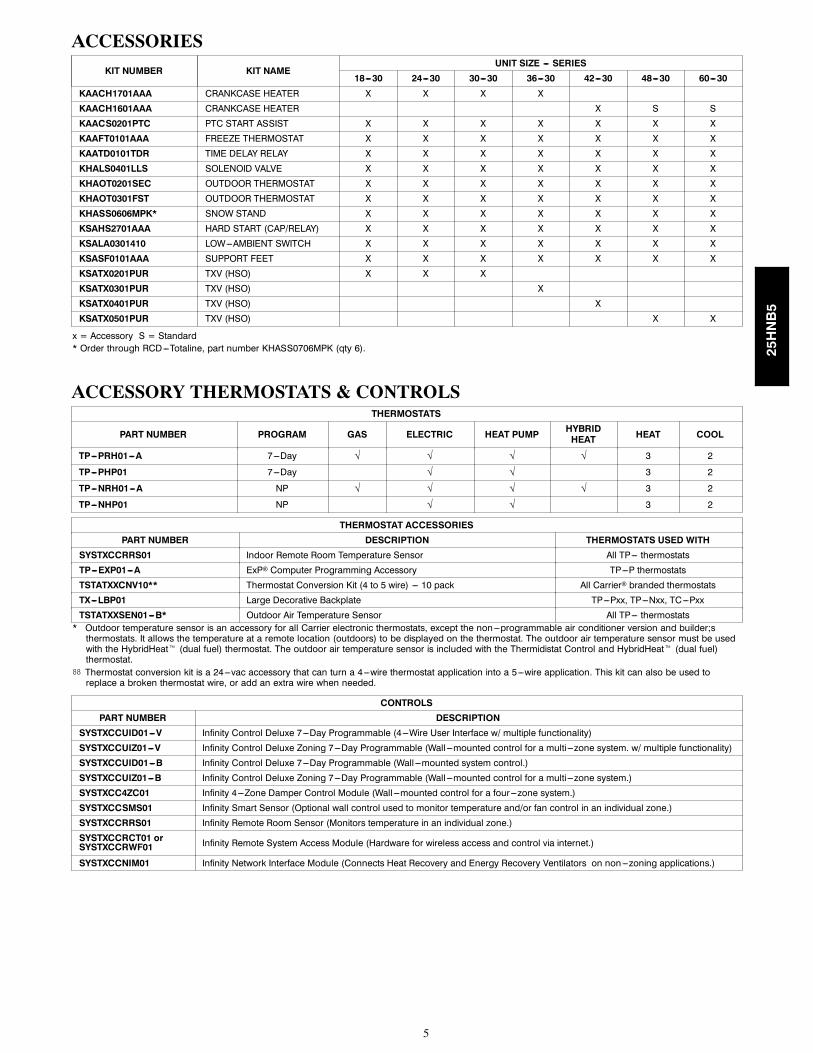
ACCESSORIES
KIT NUMBER KIT NAMEUNIT SIZE --- SERIES
18---30 24---30 30---30 36---30 42---30 48---30 60---30
KAACH1701AAA CRANKCASE HEATER X X X X
KAACH1601AAA CRANKCASE HEATER X S S
KAACS0201PTC PTC START ASSIST X X X X X X X
KAAFT0101AAA FREEZE THERMOSTAT X X X X X X X
KAATD0101TDR TIME DELAY RELAY X X X X X X X
KHALS0401LLS SOLENOID VALVE X X X X X X X
KHAOT0201SEC OUTDOOR THERMOSTAT X X X X X X X
KHAOT0301FST OUTDOOR THERMOSTAT X X X X X X X
KHASS0606MPK* SNOW STAND X X X X X X X
KSAHS2701AAA HARD START (CAP/RELAY) X X X X X X X
KSALA0301410 LOW---AMBIENT SWITCH X X X X X X X
KSASF0101AAA SUPPORT FEET X X X X X X X
KSATX0201PUR TXV (HSO) X X X
KSATX0301PUR TXV (HSO) X
KSATX0401PUR TXV (HSO) X
KSATX0501PUR TXV (HSO) X X
x = Accessory S = Standard* Order through RCD---Totaline, part number KHASS0706MPK (qty 6).
ACCESSORY THERMOSTATS & CONTROLSTHERMOSTATS
PART NUMBER PROGRAM GAS ELECTRIC HEAT PUMP HYBRIDHEAT HEAT COOL
TP---PRH01---A 7---Day √ √ √ √ 3 2
TP---PHP01 7---Day √ √ 3 2
TP---NRH01---A NP √ √ √ √ 3 2
TP---NHP01 NP √ √ 3 2
THERMOSTAT ACCESSORIES
PART NUMBER DESCRIPTION THERMOSTATS USED WITH
SYSTXCCRRS01 Indoor Remote Room Temperature Sensor All TP--- thermostats
TP---EXP01---A ExP Computer Programming Accessory TP---P thermostats
TSTATXXCNV10** Thermostat Conversion Kit (4 to 5 wire) --- 10 pack All Carrier branded thermostats
TX---LBP01 Large Decorative Backplate TP---Pxx, TP---Nxx, TC---Pxx
TSTATXXSEN01---B* Outdoor Air Temperature Sensor All TP--- thermostats* Outdoor temperature sensor is an accessory for all Carrier electronic thermostats, except the non---programmable air conditioner version and builder;sthermostats. It allows the temperature at a remote location (outdoors) to be displayed on the thermostat. The outdoor air temperature sensor must be usedwith the HybridHeatt (dual fuel) thermostat. The outdoor air temperature sensor is included with the Thermidistat Control and HybridHeatt (dual fuel)thermostat.
** Thermostat conversion kit is a 24---vac accessory that can turn a 4---wire thermostat application into a 5---wire application. This kit can also be used toreplace a broken thermostat wire, or add an extra wire when needed.
CONTROLS
PART NUMBER DESCRIPTION
SYSTXCCUID01---V Infinity Control Deluxe 7---Day Programmable (4---Wire User Interface w/ multiple functionality)
SYSTXCCUIZ01---V Infinity Control Deluxe Zoning 7---Day Programmable (Wall ---mounted control for a multi---zone system. w/ multiple functionality)
SYSTXCCUID01---B Infinity Control Deluxe 7---Day Programmable (Wall ---mounted system control.)
SYSTXCCUIZ01---B Infinity Control Deluxe Zoning 7---Day Programmable (Wall ---mounted control for a multi---zone system.)
SYSTXCC4ZC01 Infinity 4---Zone Damper Control Module (Wall ---mounted control for a four ---zone system.)
SYSTXCCSMS01 Infinity Smart Sensor (Optional wall control used to monitor temperature and/or fan control in an individual zone.)
SYSTXCCRRS01 Infinity Remote Room Sensor (Monitors temperature in an individual zone.)
SYSTXCCRCT01 orSYSTXCCRWF01 Infinity Remote System Access Module (Hardware for wireless access and control via internet.)
SYSTXCCNIM01 Infinity Network Interface Module (Connects Heat Recovery and Energy Recovery Ventilators on non---zoning applications.)
25HNB5

6
ACCESSORY USAGE GUIDELINE
AccessoryREQUIRED FOR
LONG LINE APPLICATIONS*
REQUIRED FORSEA COAST APPLICATIONS (Within 2
miles / 3.22 km)Accumulator Standard Standard
Ball Bearing Fan Motor Standard StandardCompressor Start Assist Capacitor and Relay Yes No
Crankcase Heater Yes No
Evaporator Freeze Thermostat No NoHard Shutoff TXV Yes YesIsolation Relay No No
Liquid Line Solenoid Valve See Long---Line Application Guideline NoLow Ambient Switch No NoSupport Feet No Recommended
* For tubing line sets between 80 and 200 ft. (24.38 and 60.96 m) and/or 20 ft. (6.09 m) vertical differential, refer to Residential Piping and Longline Guideline.
Accessory Description and Usage (Listed Alphabetically)1. Compressor Start Assist -- Capacitor and RelayStart capacitor and relay gives a ”hard” boost to compressor motorat each start up.
Usage Guideline:
Required for reciprocating compressors in the followingapplications:
Long line
Low ambient cooling
Hard shut off expansion valve on indoor coil
Liquid line solenoid on indoor coil
Required for single--phase scroll compressors in thefollowing applications:
Long line
Low ambient cooling
Suggested for all compressors in areas with a history oflow voltage problems.
2. Compressor Start Assist — PTC TypeSolid state electrical device which gives a ”soft” boost to thecompressor at each start--up.
Usage Guideline:
Suggested in installations with marginal power supply.
3. Crankcase HeaterAn electric resistance heater which mounts to the base of thecompressor to keep the lubricant warm during off cycles. Improvescompressor lubrication on restart and minimizes the chance ofliquid slugging.
Usage Guideline:
Required in low ambient cooling applications.
Required in long line applications.
Suggested in all commercial applications.
4. Evaporator Freeze ThermostatAn SPST temperature--actuated switch that stops unit operationwhen evaporator reaches freeze--up conditions.
Usage Guideline:
Required when low ambient kit has been added.
5. Isolation RelayAn SPDT relay which switches the low--ambient controller out ofthe outdoor fan motor circuit when the heat pump switches toheating mode.
Usage Guideline:
Required in all heat pumps where low ambient kit hasbeen added.
6. Liquid--Line Solenoid Valve (LLS)An electrically operated shutoff valve which stops and startsrefrigerant liquid flow in response to compressor operation. It is tobe installed at the outdoor unit to control refrigerant off cyclemigration in the heating mode.
Usage Guideline:
An LLS is required in all long line heat pumpapplications to control refrigerant off cycle migration inthe heating mode. See Long Line Guideline.
7. Low--Ambient Pressure Switch KitA long life pressure switch which is mounted to outdoor unitservice valve. It is designed to cycle the outdoor fan motor in orderto maintain head pressure within normal operating limits. Thecontrol will maintain working head pressure at low--ambienttemperatures down to 0_F (--17.8_C) when properly installed.
Usage Guideline:
A Low--Ambient Pressure Switch or MotorMasterrLow--Ambient Controller must be used when coolingoperation is used at outdoor temperatures below 55_F(12.8_C).
8. Outdoor Air Temperature SensorDesigned for use with Carrier Thermostats listed in thispublication. This device enables the thermostat to display theoutdoor temperature. This device also is required to enable specialthermostat features such as auxiliary heat lock out.
Usage Guideline:
Suggested for all Carrier thermostats listed in thispublication.
25HNB5

7
Accessory Description and Usage (Listed Alphabetically) -- CONTINUED
9. Outdoor ThermostatAn SPDT temperature--actuated switch which turns onsupplemental electric heaters when outdoor air temperature dropsbelow a user--selected set point.
Usage Guideline:
Electric supplemental heat applications in non--variablespeed indoor units when electric heat staging is desired.
10. Secondary Outdoor ThermostatAn SPDT temperature--actuated switch which turns on third--stageof supplemental electric heaters when outdoor air temperaturedrops below the second--stage set point.
Usage Guideline:
Outdoor thermostat applications where electric heater iscapable of 3--stage operation.
11. Snow StandCoated wire rack which supports unit 18 in. (457.2 mm) abovemounting pad to allow for drainage from unit base.
Usage Guideline:
Suggested in the following applications:
Heat pump installations in heavy snowfall areas.
Heat pump installations in snow drift locations.
Heat pump installations in areas of prolongedsubfreezing temperatures.
All commercial installations.
Note: Snow stand does not support 26” X 26” (660 X 660 mm)small basepan size.
12. Thermostatic Expansion Valve (TXV) Bi--FlowA modulating flow--control valve which meters refrigerant liquidflow rate into the evaporator in response to the superheat of therefrigerant gas leaving the evaporator.
Usage Guideline:
Accessory required to meet AHRI rating and systemreliability, where indoor not equipped.
Required in all heat pump applications designed withPuron refrigerant.
13. Time--Delay RelayAn SPST delay relay which briefly continues operation of indoorblower motor to provide additional cooling after the compressorcycles off.
Note:Most indoor unit controls include this feature. For those thatdo not, use the guideline below.
Usage Guideline:
Accessory required to meet AHRI rating, where indoornot equipped.
25HNB5

8
ELECTRICAL DATA
UNIT SIZE--- SERIES V/PH
OPER VOLTS* COMPR FANMCA
MINWIRESIZE{
MINWIRESIZE{
MAXLENGTHft (m)}
MAXLENGTHft (m)}
MAXFUSE**or CKTBRKAMPSMAX MIN LRA RLA FLA 60 C 75 C 60 C 75 C
18---30
208/230/1 253 197
48.0 9.0 0.5 11.8 14 14 66 (20.1) 62 (20.7) 2024---30 58.3 12.8 0.5 16.5 14 14 46 (14.0) 44 (13.4) 2530---30 73.0 14.1 0.9 18.5 14 14 41 (12.4) 39 (11.8) 3036---30 79.0 16.7 1.2 22.1 12 12 57 (17.4) 54 (16.5) 3542---30 109.0 21.1 1.2 27.6 10 10 71 (21.6) 68 (20.7) 4048---30 117.0 21.8 1.2 28.5 10 10 69 (21.0) 66 (20.1) 4060---30 134.0 26.4 1.2 34.2 8 10 91 (27.7) 56 (17.1) 50
* Permissible limits of the voltage range at which the unit will operate satisfactorily{ If wire is applied at ambient greater than 30_C, consult table 310---16 of the NEC (NFPA 70). The ampacity of non---metallic---sheathed cable (NM),trade name ROMEX, shall be that of 60_C conditions, per the NEC (NFPA 70) Article 336---26. If other than uncoated (no---plated), 60 or 75_Cinsulation, copper wire (solid wire for 10 AWG or smaller, stranded wire for larger than 10 AWG) is used, consult applicable tables of the NEC (NFPA70).
} Length shown is as measured 1 way along wire path between unit and service panel for voltage drop not to exceed 2%.** Time---Delay fuse.FLA --- Full Load AmpsLRA --- Locked Rotor AmpsMCA --- Minimum Circuit AmpsRLA --- Rated Load AmpsNOTE: Control circuit is 24---V on all units and requires external power source. Copper wire must be used from service disconnect to unit.All motors/compressors contain internal overload protection.Complies with 2007 requirements of ASHRAE Standards 90.1
A--WEIGHTED SOUND LEVEL (dBA)
UNIT SIZE --- SERIESSTANDARDRATINGdBA
TYPICAL OCTAVE BAND SPECTRUM (Dba, without tone adjustment)
125 250 500 1000 2000 4000 8000
18---30 68 56.0 58.0 62.0 63.0 60.0 54.5 45.024---30 68 52.5 56.5 60.5 61.5 61.5 57.0 49.030---30 70 55.5 60.0 62.5 64.0 61.5 58.0 49.036---30 70 53.5 59.5 62.0 65.0 62.0 58.5 52.537---30 69 55.0 60.5 63.0 63.5 60.5 57.0 49.042---30 73 59.5 64.5 65.5 67.5 63.5 58.0 53.048---30 73 57.5 64.5 67.0 67.5 61.5 57.0 50.560---30 70 56.5 62.0 64.5 64.0 60.5 58.5 51.5
NOTE: Tested in accordance with AHRI Standard 270---08 (not listed in AHRI).
CHARGING SUBCOOLING (TXV--TYPE EXPANSION DEVICE)UNIT SIZE---SERIES REQUIRED SUBCOOLING _F (_C)
18---30 12 (6.7)24---30 14 (7.8)30---30 10 (5.6)36---30 10 (5.6)42---30 10 (5.6)48---30 13 (7.2)60---30 11 (6.1)
25HNB5

9
DIM
ENSIONS--ENGLISH
25HNB6
10
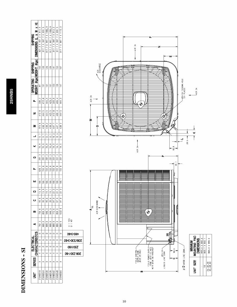
DIM
ENSIONS--SI
25HNB5

11
BALANCEPOINTWORKSH
EET
0.0
2.9
5.9
8.8
11.7
14.6
17.6
20.5
23.4
01020304050607080
kW
MBTUH
OU
TDO
OR
TEM
PERA
TUR
E, ºF
ºC
BA
SE
D O
N IN
DO
OR
EN
T. A
IR A
T70
ºF /
21.1
ºC A
ND
RA
TED
AT
CFM
25H
NB
518A
30FX
4DN
F019
25H
NB
524A
30FX
4DN
F025
25H
NB
542A
30FX
4DN
F043
25H
NB
530A
30FX
4DN
F031
25H
NB
560A
30FX
4DN
F061
25H
NB
548A
30FX
4DN
F049
25H
NB
536A
30FX
4DN
F037
BUILDING HEAT LOSS, UNIT INTEGRATED HEATING CAPACITY,
10 (-
23.3
)0
(-17
.8)
10 (-
12.2
)20
(-6.
7)30
(-1.
1)40
(4.4
)50
(10.
0)60
(15.
6)70
(21.
1)80
(26.
7)
25HNB5

12
CLEARANCES
Cle
aran
ces
(var
iou
s ex
amp
les)
Wal
l
Wal
l
Wal
l
Wall24
”S
ervi
ce
6”
(152
.4 m
m)
24”
(609
.6)
Ser
vice
24”
(609
.6)
Ser
vice
24”
(609
.6)
Ser
vice
24”
(609
.6)
Ser
vice
24”
(609
.6)
24”
(609
.6)
24”
(609
.6)
12”
(304
.8)
12”
(304
.8)
12”
(304
.8)
12”
(304
.8)
6”
(152
.4)
No
te:
Nu
mb
ers
in (
) =
mm
A07833
IMPORTANT:Wheninstallingmultipleunitsinan
alcove,roofwell,or
partially
enclosed
area,ensurethereisadequateventilation
topreventre--circulation
ofdischargeair.
25HNB5

13
TESTED AHRI COMBINATION RATINGS*
NOTE: Ratings contained in this document are subject to change at any time.
For AHRI ratings certificates, please refer to the AHRI directory www.ahridirectory.orgAdditional ratings and system combinations can be accessed via the Carrier database at:http://cactaxcredits.info/carrier-ratings/ac_ratings_srch.php
Equipment performance calculator can be accessed at: http://rpmob.wrightsoft.com/
Model Number Coil Model Number Furnace ModelNumber
Cooling Ca-pacity EER SEER
High TempHSPF
Low TempE
CapacityECOP
HCapacity
HCOP
25HNB518A**30 FX4DNF019 18,000 12.5 15.0 17,700 3.86 8.5 10,600 2.5625HNB524A**30 FX4DNF025 24,000 12.5 15.0 24,000 3.92 9.0 14,800 2.6825HNB530A**30 FX4DN(B,F)031 28,800 12.5 15.0 29,600 3.92 8.5 17,300 2.5825HNB536A**30 FX4DN(B,F)037 35,200 12.5 15.0 35,000 3.88 8.7 21,800 2.6425HNB537A**30 CAP**3617A** 59*N*A060V17**14 33,800 12.5 15.0 35,000 3.54 8.0 21,000 2.5025HNB542A**30 FX4DN(B,F)043 42,000 12.5 15.0 42,000 3.80 8.5 26,800 2.5825HNB548A**30 FX4DN(B,F)049 47,500 12.5 15.0 47,000 3.84 8.7 28,000 2.6625HNB560A**30 FX4DN(B,F)061 58,000 12.5 15.0 57,500 3.84 8.5 35,400 2.68
* AHRI = Air Conditioning, Heating & Refrigeration InstituteRatings are net values reflecting the effects of circulating fan heat. Supplemental electric heat is not included. Ratings are based on:Cooling Standard: 80_F (27_C) db 67_F (19_C) wb indoor entering air temperature and 95_F (35_C) db air entering outdoor unit.High---Temp Heating Standard: 70_F (21_C) db indoor entering air temperature and 47_F (8_C) db 43° F (6_C) wb air entering outdoor unit.Low---Temp Heating Standard: 70_F (21_C) db indoor entering air temperature and 17_F (---8_C) db 15° F (---9_C) wb air entering outdoor unit.COP— Coefficient of PerformanceEER— Energy Efficiency RatioHSPF— Heating Seasonal Performance FactorSEER— Seasonal Energy Efficiency Ratio
25HNB5
14
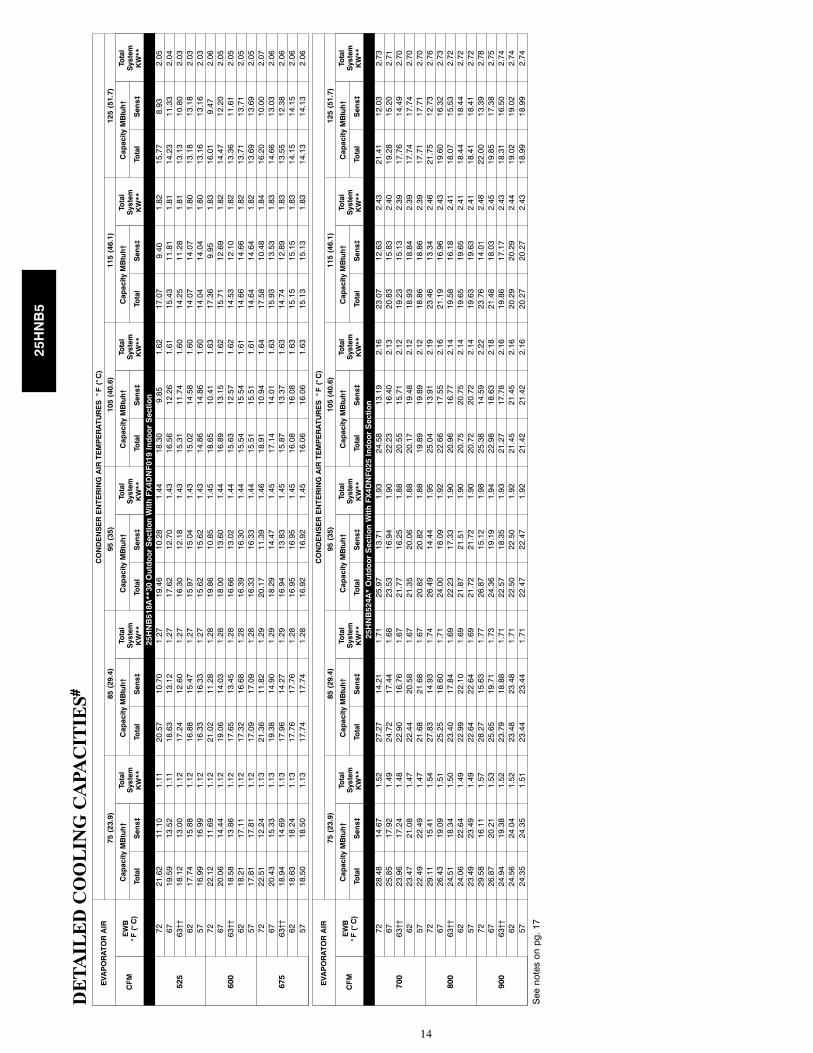
DETAILEDCOOLINGCAPA
CITIES#
EVAPORATORAIR
CONDENSERENTERINGAIRTEMPERATURES°F(°C)
75(23.9)
85(29.4)
95(35)
105(40.6)
115(46.1)
125(51.7)
CFM
EWB
°F(°C)
CapacityMBtuh†
Total
System
KW**
CapacityMBtuh†
Total
System
KW**
CapacityMBtuh†
Total
System
KW**
CapacityMBtuh†
Total
System
KW**
CapacityMBtuh†
Total
System
KW**
CapacityMBtuh†
Total
System
KW**
Total
Sens‡
Total
Sens‡
Total
Sens‡
Total
Sens‡
Total
Sens‡
Total
Sens‡
25HNB518A**30OutdoorSectionWithFX4DNF019IndoorSection
525
7221.62
11.10
1.11
20.57
10.70
1.27
19.46
10.28
1.44
18.30
9.85
1.62
17.07
9.40
1.82
15.77
8.93
2.05
6719.59
13.52
1.11
18.63
13.12
1.27
17.62
12.70
1.43
16.56
12.26
1.61
15.43
11.81
1.81
14.23
11.33
2.04
63††
18.12
13.00
1.12
17.24
12.60
1.27
16.30
12.18
1.43
15.31
11.74
1.60
14.25
11.28
1.81
13.13
10.80
2.03
6217.74
15.88
1.12
16.88
15.47
1.27
15.97
15.04
1.43
15.02
14.58
1.60
14.07
14.07
1.80
13.18
13.18
2.03
5716.99
16.99
1.12
16.33
16.33
1.27
15.62
15.62
1.43
14.86
14.86
1.60
14.04
14.04
1.80
13.16
13.16
2.03
600
7222.12
11.69
1.12
21.02
11.28
1.28
19.86
10.85
1.45
18.65
10.41
1.63
17.36
9.95
1.83
16.01
9.47
2.06
6720.06
14.44
1.12
19.06
14.03
1.28
18.00
13.60
1.44
16.89
13.15
1.62
15.71
12.69
1.82
14.47
12.20
2.05
63††
18.58
13.86
1.12
17.65
13.45
1.28
16.66
13.02
1.44
15.63
12.57
1.62
14.53
12.10
1.82
13.36
11.61
2.05
6218.21
17.11
1.12
17.32
16.68
1.28
16.39
16.30
1.44
15.54
15.54
1.61
14.66
14.66
1.82
13.71
13.71
2.05
5717.81
17.81
1.12
17.09
17.09
1.28
16.33
16.33
1.44
15.51
15.51
1.61
14.64
14.64
1.82
13.69
13.69
2.05
675
7222.51
12.24
1.13
21.36
11.82
1.29
20.17
11.39
1.46
18.91
10.94
1.64
17.58
10.48
1.84
16.20
10.00
2.07
6720.43
15.33
1.13
19.38
14.90
1.29
18.29
14.47
1.45
17.14
14.01
1.63
15.93
13.53
1.83
14.66
13.03
2.06
63††
18.94
14.69
1.13
17.96
14.27
1.29
16.94
13.83
1.45
15.87
13.37
1.63
14.74
12.89
1.83
13.55
12.38
2.06
6218.63
18.24
1.13
17.76
17.76
1.28
16.95
16.95
1.45
16.08
16.08
1.63
15.15
15.15
1.83
14.15
14.15
2.06
5718.50
18.50
1.13
17.74
17.74
1.28
16.92
16.92
1.45
16.06
16.06
1.63
15.13
15.13
1.83
14.13
14.13
2.06
EVAPORATORAIR
CONDENSERENTERINGAIRTEMPERATURES°F(°C)
75(23.9)
85(29.4)
95(35)
105(40.6)
115(46.1)
125(51.7)
CFM
EWB
°F(°C)
CapacityMBtuh†
Total
System
KW**
CapacityMBtuh†
Total
System
KW**
CapacityMBtuh†
Total
System
KW**
CapacityMBtuh†
Total
System
KW**
CapacityMBtuh†
Total
System
KW**
CapacityMBtuh†
Total
System
KW**
Total
Sens‡
Total
Sens‡
Total
Sens‡
Total
Sens‡
Total
Sens‡
Total
Sens‡
25HNB524A*OutdoorSectionWithFX4DNF025IndoorSection
700
7228.48
14.67
1.52
27.27
14.21
1.71
25.97
13.71
1.93
24.58
13.19
2.16
23.07
12.63
2.43
21.41
12.03
2.73
6725.85
17.92
1.49
24.72
17.44
1.68
23.53
16.94
1.90
22.23
16.40
2.13
20.83
15.83
2.40
19.28
15.20
2.71
63††
23.96
17.24
1.48
22.90
16.76
1.67
21.77
16.25
1.88
20.55
15.71
2.12
19.23
15.13
2.39
17.76
14.49
2.70
6223.47
21.08
1.47
22.44
20.58
1.67
21.35
20.06
1.88
20.17
19.48
2.12
18.93
18.84
2.39
17.74
17.74
2.70
5722.49
22.49
1.47
21.68
21.68
1.67
20.82
20.82
1.88
19.89
19.89
2.12
18.86
18.86
2.39
17.71
17.71
2.70
800
7229.11
15.41
1.54
27.83
14.93
1.74
26.49
14.44
1.95
25.04
13.91
2.19
23.46
13.34
2.46
21.75
12.73
2.76
6726.43
19.09
1.51
25.25
18.60
1.71
24.00
18.09
1.92
22.66
17.55
2.16
21.19
16.96
2.43
19.60
16.32
2.73
63††
24.51
18.34
1.50
23.40
17.84
1.69
22.23
17.33
1.90
20.96
16.77
2.14
19.58
16.18
2.41
18.07
15.53
2.72
6224.06
22.64
1.49
22.99
22.10
1.69
21.87
21.51
1.90
20.75
20.75
2.14
19.65
19.65
2.41
18.44
18.44
2.72
5723.49
23.49
1.49
22.64
22.64
1.69
21.72
21.72
1.90
20.72
20.72
2.14
19.63
19.63
2.41
18.41
18.41
2.72
900
7229.58
16.11
1.57
28.27
15.63
1.77
26.87
15.12
1.98
25.38
14.59
2.22
23.76
14.01
2.48
22.00
13.39
2.78
6726.87
20.21
1.53
25.65
19.71
1.73
24.36
19.19
1.94
22.98
18.63
2.18
21.48
18.03
2.45
19.85
17.38
2.75
63††
24.94
19.38
1.52
23.79
18.88
1.71
22.57
18.35
1.93
21.27
17.78
2.16
19.86
17.17
2.43
18.31
16.50
2.74
6224.56
24.04
1.52
23.48
23.48
1.71
22.50
22.50
1.92
21.45
21.45
2.16
20.29
20.29
2.44
19.02
19.02
2.74
5724.35
24.35
1.51
23.44
23.44
1.71
22.47
22.47
1.92
21.42
21.42
2.16
20.27
20.27
2.43
18.99
18.99
2.74
Seenotesonpg.17
25HNB5
15
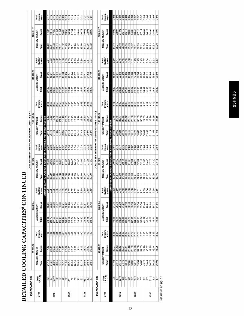
DETAILEDCOOLINGCAPA
CITIES#CONTINUED
EVAPORATORAIR
CONDENSERENTERINGAIRTEMPERATURES°F(°C)
75(23.9)
85(29.4)
95(35)
105(40.6)
115(46.1)
125(51.7)
CFM
EWB
°F(°C)
CapacityMBtuh†
Total
System
KW**
CapacityMBtuh†
Total
System
KW**
CapacityMBtuh†
Total
System
KW**
CapacityMBtuh†
Total
System
KW**
CapacityMBtuh†
Total
System
KW**
CapacityMBtuh†
Total
System
KW**
Total
Sens‡
Total
Sens‡
Total
Sens‡
Total
Sens‡
Total
Sens‡
Total
Sens‡
25HNB530A**30OutdoorSectionWithFX4DN(B,F)031IndoorSection
875
7234.43
17.43
1.86
32.86
16.85
2.06
31.21
16.24
2.29
29.48
15.62
2.55
27.60
14.95
2.84
25.58
14.24
3.17
6731.21
21.41
1.85
29.79
20.83
2.05
28.29
20.22
2.28
26.70
19.59
2.53
24.98
18.91
2.83
23.11
18.18
3.16
63††
28.90
20.58
1.84
27.58
20.00
2.05
26.18
19.39
2.27
24.70
18.75
2.53
23.09
18.07
2.82
21.33
17.32
3.16
6228.35
25.28
1.84
27.08
24.67
2.05
25.75
24.02
2.27
24.35
23.29
2.53
22.94
22.94
2.82
21.54
21.54
3.16
5727.41
27.41
1.84
26.40
26.40
2.04
25.33
25.33
2.27
24.17
24.17
2.53
22.91
22.91
2.82
21.51
21.51
3.16
1000
7235.12
18.31
1.88
33.47
17.71
2.09
31.76
17.10
2.32
29.95
16.46
2.57
28.01
15.78
2.86
25.92
15.06
3.20
6731.86
22.82
1.87
30.36
22.22
2.08
28.80
21.60
2.30
27.15
20.95
2.56
25.36
20.25
2.85
23.45
19.50
3.19
63††
29.51
21.88
1.87
28.12
21.28
2.07
26.68
20.67
2.30
25.13
20.01
2.55
23.47
19.31
2.85
21.66
18.54
3.19
6229.05
27.10
1.87
27.74
26.42
2.07
26.40
26.40
2.30
25.15
25.15
2.55
23.80
23.80
2.85
22.31
22.31
3.19
5728.58
28.58
1.87
27.50
27.50
2.07
26.35
26.35
2.30
25.12
25.12
2.55
23.77
23.77
2.85
22.28
22.28
3.19
1125
7235.65
19.14
1.91
33.95
18.52
2.12
32.17
17.90
2.34
30.31
17.26
2.60
28.32
16.57
2.89
26.17
15.84
3.22
6732.35
24.15
1.90
30.80
23.54
2.10
29.19
22.91
2.33
27.48
22.24
2.58
25.67
21.52
2.88
23.70
20.73
3.21
63††
29.99
23.12
1.89
28.55
22.51
2.10
27.05
21.87
2.32
25.46
21.20
2.58
23.76
20.47
2.87
21.92
19.66
3.21
6229.68
29.50
1.89
28.46
28.46
2.10
27.24
27.24
2.32
25.94
25.94
2.58
24.52
24.52
2.87
22.95
22.95
3.21
5729.56
29.56
1.89
28.42
28.42
2.10
27.20
27.20
2.32
25.91
25.91
2.58
24.49
24.49
2.87
22.92
22.92
3.21
EVAPORATORAIR
CONDENSERENTERINGAIRTEMPERATURES°F(°C)
75(23.9)
85(29.4)
95(35)
105(40.6)
115(46.1)
125(51.7)
CFM
EWB
°F(°C)
CapacityMBtuh†
Total
System
KW**
CapacityMBtuh†
Total
System
KW**
CapacityMBtuh†
Total
System
KW**
CapacityMBtuh†
Total
System
KW**
CapacityMBtuh†
Total
System
KW**
CapacityMBtuh†
Total
System
KW**
Total
Sens‡
Total
Sens‡
Total
Sens‡
Total
Sens‡
Total
Sens‡
Total
Sens‡
25HNB536A*OutdoorSectionWithFX4DNF037IndoorSection
1050
7241.83
22.07
2.26
39.98
21.35
2.52
37.99
20.58
2.81
35.88
19.78
3.13
33.60
18.93
3.50
31.14
18.02
3.92
6738.11
27.12
2.24
36.41
26.38
2.50
34.57
25.60
2.78
32.60
24.78
3.10
30.49
23.91
3.47
28.21
22.97
3.90
63††
35.42
26.13
2.23
33.81
25.39
2.48
32.09
24.60
2.77
30.24
23.77
3.09
28.25
22.88
3.46
26.10
21.93
3.89
6234.72
32.04
2.23
33.16
31.27
2.48
31.49
30.44
2.76
29.72
29.53
3.08
27.90
27.90
3.46
26.19
26.19
3.89
5733.41
33.41
2.22
32.19
32.19
2.48
30.86
30.86
2.76
29.42
29.42
3.08
27.86
27.86
3.46
26.15
26.15
3.89
1200
7242.65
23.16
2.29
40.73
22.43
2.56
38.66
21.66
2.84
36.45
20.84
3.17
34.10
19.98
3.53
31.56
19.05
3.95
6738.90
28.89
2.27
37.11
28.13
2.53
35.20
27.34
2.82
33.16
26.50
3.14
30.97
25.60
3.51
28.62
24.65
3.93
63††
36.18
27.78
2.26
34.50
27.02
2.52
32.71
26.22
2.80
30.78
25.37
3.12
28.72
24.46
3.49
26.51
23.49
3.92
6235.54
34.38
2.26
33.93
33.54
2.51
32.25
32.04
2.80
30.63
30.63
3.12
28.96
28.96
3.49
27.15
27.15
3.92
5734.85
34.85
2.25
33.54
33.54
2.51
32.12
32.12
2.79
30.58
30.58
3.12
28.92
28.92
3.49
27.11
27.11
3.92
1350
7243.28
24.20
2.33
41.29
23.46
2.59
39.15
22.68
2.88
36.89
21.85
3.20
34.47
20.98
3.57
31.86
20.04
3.99
6739.49
30.57
2.30
37.64
29.81
2.56
35.67
29.00
2.85
33.57
28.14
3.17
31.33
27.22
3.54
28.93
26.23
3.96
63††
36.76
29.35
2.29
35.02
28.58
2.55
33.17
27.76
2.83
31.19
26.89
3.15
29.08
25.95
3.52
26.82
24.94
3.95
6236.25
36.44
2.29
34.71
34.71
2.55
33.20
33.20
2.83
31.59
31.59
3.15
29.84
29.84
3.53
27.93
24.94
3.95
5736.05
36.05
2.29
34.66
34.66
2.55
33.16
33.16
2.83
31.55
31.55
3.15
29.80
29.80
3.53
27.90
24.94
3.95
Seenotesonpg.17
25HNB5

16
DETAILEDCOOLINGCAPA
CITIES#CONTINUED
EVAPORATORAIR
CONDENSERENTERINGAIRTEMPERATURES°F(°C)
75(23.9)
85(29.4)
95(35)
105(40.6)
115(46.1)
125(51.7)
CFM
EWB
°F(°C)
CapacityMBtuh†
Total
System
KW**
CapacityMBtuh†
Total
System
KW**
CapacityMBtuh†
Total
System
KW**
CapacityMBtuh†
Total
System
KW**
CapacityMBtuh†
Total
System
KW**
CapacityMBtuh†
Total
System
KW**
Total
Sens‡
Total
Sens‡
Total
Sens‡
Total
Sens‡
Total
Sens‡
Total
Sens‡
25HNB542A*OutdoorSectionWithFX4DNF043IndoorSection
1225
7250.43
25.70
2.47
48.01
24.76
2.86
45.51
23.81
3.26
42.89
22.83
3.69
40.16
21.82
4.13
37.25
20.76
4.61
6745.65
31.32
2.59
43.47
30.39
2.96
41.22
29.44
3.33
38.86
28.47
3.73
36.38
27.46
4.15
33.74
26.40
4.62
63††
42.23
30.12
2.67
40.23
29.20
3.01
38.16
28.26
3.36
35.97
27.30
3.74
33.68
26.29
4.16
31.23
25.22
4.61
6241.36
36.82
2.68
39.42
35.88
3.02
37.42
34.91
3.37
35.33
33.87
3.75
33.17
32.70
4.16
31.09
31.09
4.61
5739.50
39.50
2.72
38.01
38.01
3.04
36.44
36.44
3.38
34.77
34.77
3.75
32.98
32.98
4.16
31.05
31.05
4.61
1400
7251.53
26.95
2.47
48.98
25.98
2.88
46.35
25.01
3.29
43.62
24.01
3.72
40.76
22.98
4.17
37.75
21.90
4.65
6746.66
33.31
2.60
44.38
32.35
2.98
42.00
31.37
3.36
39.54
30.39
3.76
36.95
29.35
4.19
34.21
28.25
4.66
63††
43.19
31.97
2.69
41.08
31.02
3.04
38.90
30.06
3.40
36.62
29.07
3.78
34.22
28.03
4.20
31.69
26.94
4.66
6242.36
39.45
2.70
40.35
38.44
3.05
38.28
37.36
3.40
36.20
36.20
3.78
34.27
34.27
4.20
32.20
32.20
4.66
5741.23
41.23
2.72
39.62
39.62
3.06
37.93
37.93
3.41
36.14
36.14
3.78
34.22
34.22
4.20
32.16
32.16
4.66
1575
7252.37
28.11
2.48
49.72
27.13
2.90
47.00
26.14
3.31
44.15
25.12
3.75
41.21
24.07
4.20
38.11
22.98
4.69
6747.45
35.19
2.62
45.05
34.20
3.00
42.59
33.23
3.39
40.05
32.20
3.80
37.37
31.13
4.23
34.58
30.00
4.70
63††
43.93
33.72
2.71
41.73
32.75
3.07
39.46
31.77
3.43
37.10
30.75
3.82
34.64
29.68
4.24
32.04
28.54
4.70
6243.23
41.84
2.72
41.18
40.82
3.07
39.23
39.23
3.43
37.32
37.32
3.82
35.29
35.29
4.24
33.12
33.12
4.70
5742.69
42.69
2.73
40.98
40.98
3.08
39.18
39.18
3.44
37.28
37.28
3.82
35.25
35.25
4.24
33.08
33.08
4.70
EVAPORATORAIR
CONDENSERENTERINGAIRTEMPERATURES°F(°C)
75(23.9)
85(29.4)
95(35)
105(40.6)
115(46.1)
125(51.7)
CFM
EWB
°F(°C)
CapacityMBtuh†
Total
System
KW**
CapacityMBtuh†
Total
System
KW**
CapacityMBtuh†
Total
System
KW**
CapacityMBtuh†
Total
System
KW**
CapacityMBtuh†
Total
System
KW**
CapacityMBtuh†
Total
System
KW**
Total
Sens‡
Total
Sens‡
Total
Sens‡
Total
Sens‡
Total
Sens‡
Total
Sens‡
25HNB548A*OutdoorSectionWithFX4DNF049IndoorSection
1400
7257.26
29.51
2.89
54.23
28.34
3.33
51.16
27.19
3.76
48.02
26.02
4.20
44.73
24.81
4.66
41.29
23.57
5.18
6752.18
36.28
2.93
49.48
35.14
3.34
46.73
33.99
3.75
43.90
32.83
4.18
40.93
31.62
4.64
37.80
30.36
5.15
63††
48.48
34.97
2.95
46.01
33.84
3.34
43.48
32.71
3.74
40.88
31.55
4.16
38.14
30.36
4.61
35.25
29.10
5.13
6247.52
42.88
2.95
45.12
41.72
3.34
42.69
40.54
3.74
40.19
39.27
4.15
37.70
37.70
4.61
35.35
35.35
5.13
5745.66
45.66
2.96
43.79
43.79
3.35
41.86
41.86
3.73
39.82
39.82
4.15
37.65
37.65
4.61
35.30
35.30
5.13
1600
7258.35
30.94
2.92
55.18
29.75
3.37
51.96
28.57
3.80
48.68
27.37
4.25
45.27
26.15
4.72
41.70
24.88
5.23
6753.25
38.62
2.97
50.38
37.44
3.39
47.50
36.26
3.80
44.54
35.07
4.23
41.45
33.83
4.69
38.22
32.53
5.20
63††
49.51
37.15
2.99
46.89
35.98
3.39
44.25
34.83
3.79
41.52
33.64
4.21
38.69
32.41
4.67
35.70
31.12
5.18
6248.61
45.99
3.00
46.11
44.72
3.39
43.64
43.39
3.79
41.34
41.34
4.21
39.01
39.01
4.67
36.50
36.50
5.19
5747.59
47.59
3.00
45.57
45.57
3.39
43.48
43.48
3.79
41.28
41.28
4.21
38.96
38.96
4.67
36.46
36.46
5.19
1800
7259.17
32.29
2.96
55.88
31.08
3.41
52.54
29.88
3.85
49.16
28.67
4.30
45.65
27.43
4.77
41.98
26.15
5.28
6754.02
40.84
3.01
51.05
39.64
3.43
48.06
38.43
3.85
45.00
37.20
4.28
41.84
35.93
4.74
38.52
34.58
5.25
63††
50.28
39.22
3.03
47.57
38.03
3.44
44.82
36.83
3.84
42.01
35.62
4.26
39.10
34.35
4.72
36.04
33.00
5.23
6249.55
48.76
3.04
47.11
47.11
3.44
44.87
44.87
3.84
42.54
42.54
4.27
40.07
40.07
4.73
37.40
37.40
5.25
5749.21
49.21
3.04
47.04
47.04
3.44
44.81
44.81
3.84
42.49
42.49
4.27
40.03
40.03
4.73
37.36
37.36
5.25
Seenotesonpg.17
25HNB5
17
DETAILEDCOOLINGCAPA
CITIES#CONTINUED
EVAPORATORAIR
CONDENSERENTERINGAIRTEMPERATURES°F(°C)
75(23.9)
85(29.4)
95(35)
105(40.6)
115(46.1)
125(51.7)
CFM
EWB
°F(°C)
CapacityMBtuh†
Total
System
KW**
CapacityMBtuh†
Total
System
KW**
CapacityMBtuh†
Total
System
KW**
CapacityMBtuh†
Total
System
KW**
CapacityMBtuh†
Total
System
KW**
CapacityMBtuh†
Total
System
KW**
Total
Sens‡
Total
Sens‡
Total
Sens‡
Total
Sens‡
Total
Sens‡
Total
Sens‡
25HNB560A*OutdoorSectionWithFX4DNF061IndoorSection
1750
7270.38
35.96
3.88
66.99
34.68
4.27
63.41
33.37
4.71
59.63
31.99
5.21
55.59
30.54
5.78
51.30
29.02
6.41
6764.30
44.51
3.81
61.25
43.24
4.20
58.00
41.92
4.64
54.57
40.55
5.14
50.90
39.09
5.71
46.99
37.54
6.36
63††
59.89
42.93
3.76
57.06
41.67
4.15
54.07
40.35
4.59
50.90
38.98
5.09
47.50
37.53
5.66
43.87
35.99
6.32
6258.73
52.83
3.75
56.00
51.53
4.14
53.11
50.14
4.58
50.09
48.59
5.08
47.13
47.13
5.66
44.16
44.16
6.32
5756.76
56.76
3.73
54.61
54.61
4.12
52.30
52.30
4.57
49.79
49.79
5.08
47.07
47.07
5.66
44.10
44.10
6.32
2000
7271.60
37.71
3.96
68.07
36.42
4.35
64.32
35.07
4.79
60.39
33.67
5.29
56.21
32.20
5.85
51.76
30.66
6.49
6765.47
47.38
3.89
62.28
46.09
4.28
58.90
44.75
4.72
55.31
43.33
5.22
51.52
41.84
5.79
47.47
40.25
6.43
63††
61.05
45.61
3.83
58.09
44.32
4.23
54.96
42.98
4.67
51.65
41.57
5.17
48.14
40.08
5.74
44.38
38.48
6.39
6260.01
56.64
3.83
57.18
55.19
4.22
54.33
54.33
4.66
51.62
51.62
5.17
48.70
48.70
5.75
45.53
45.53
6.41
5759.08
59.08
3.82
56.74
56.74
4.21
54.25
54.25
4.66
51.55
51.55
5.17
48.64
48.64
5.75
45.47
45.47
6.41
2250
7272.51
39.37
4.04
68.83
38.06
4.43
64.98
36.70
4.87
60.94
35.28
5.37
56.63
33.79
5.93
52.08
32.24
6.56
6766.36
50.14
3.96
63.04
48.81
4.36
59.53
47.43
4.80
55.86
45.99
5.29
51.96
44.45
5.86
47.83
42.79
6.50
63††
61.91
48.17
3.91
58.84
46.84
4.30
55.61
45.48
4.74
52.21
44.03
5.24
48.59
42.48
5.81
44.76
40.82
6.46
6261.10
61.10
3.90
58.57
58.57
4.30
55.91
55.91
4.75
53.05
53.05
5.25
49.97
49.97
5.83
46.62
46.62
6.49
5760.97
60.97
3.90
58.49
58.49
4.30
55.85
55.85
4.75
52.99
52.99
5.25
49.91
49.91
5.83
46.57
46.57
6.49
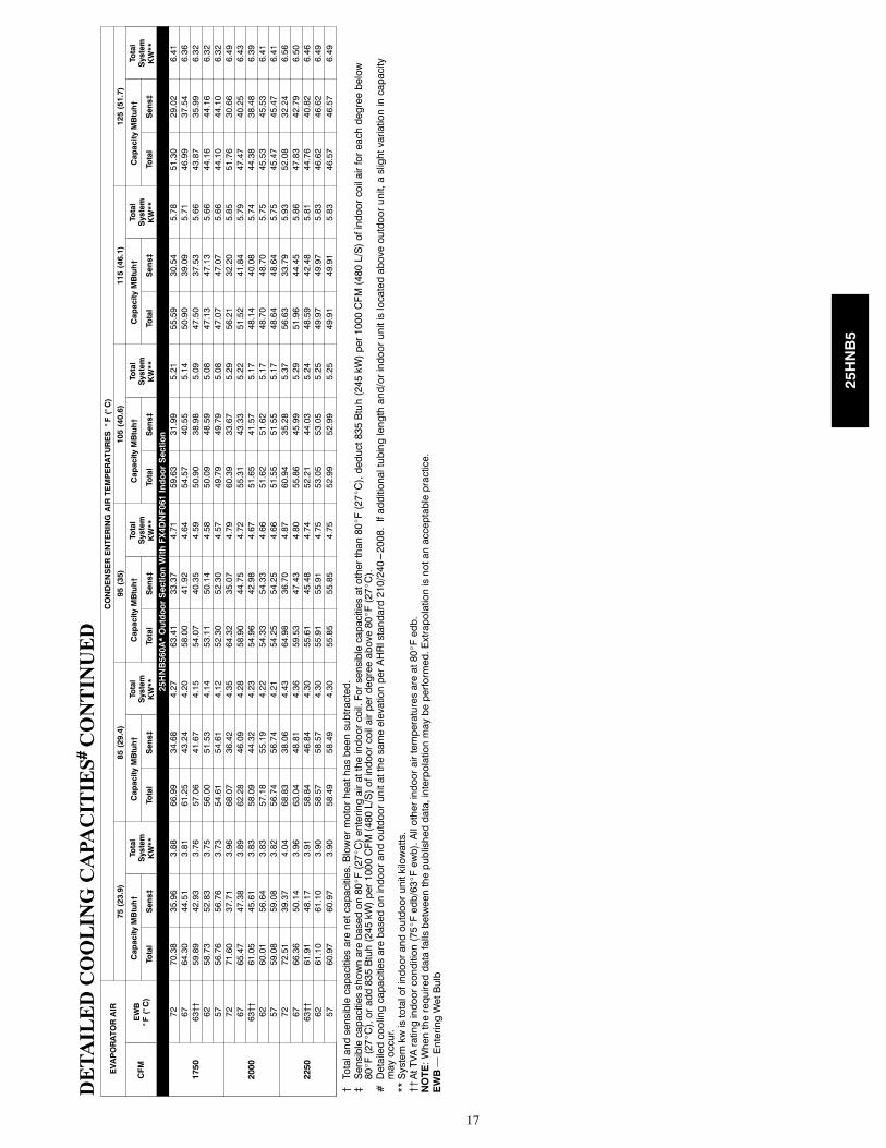
{Totalandsensiblecapacitiesarenetcapacities.Blowermotorheathasbeensubtracted.
}Sensiblecapacitiesshownarebasedon80_F(27_C)enteringairattheindoorcoil.Forsensiblecapacitiesatotherthan80_F(27_C),deduct835Btuh(245kW)per1000CFM(480L/S)ofindoorcoilairforeachdegreebelow
80_F(27_C),oradd835Btuh(245kW)per1000CFM(480L/S)ofindoorcoilairperdegreeabove80_F(27_C).
#DetailedcoolingcapacitiesarebasedonindoorandoutdoorunitatthesameelevationperAHRIstandard210/240---2008.Ifadditionaltubinglengthand/orindoorunitislocatedaboveoutdoorunit,aslightvariationincapacity
mayoccur.
**Systemkwistotalofindoorandoutdoorunitkilowatts.
{{AtTVAratingindoorcondition(75_Fedb/63_Fewb).Allotherindoorairtemperaturesareat80_Fedb.
NOTE:Whentherequireddatafallsbetweenthepublisheddata,interpolationmaybeperformed.Extrapolationisnotanacceptablepractice.
EWB—EnteringWetBulb
25HNB5

18
HEATPUMPHEATINGPERFORMANCE
INDOORAIR
OUTDOORCOILENTERINGAIRTEMPERATURES°F(°C)
---3(---19.4)
7(---13.9)
17(---8.3)
27(---2.8)
37(2.8)
47(8.3)
57(13.9)
67(19.4)
EDB
°F(°C)
CFM
CapacityMBtuh
Total
Sys.
KW†
CapacityMBtuh
Total
Sys.
KW†
CapacityMBtuh
Total
Sys.
KW†
CapacityMBtuh
Total
Sys.
KW†
CapacityMBtuh
Total
Sys.
KW†
CapacityMBtuh
Total
Sys-
tem
KW†
CapacityMBtuh
Total
Sys.
KW†
CapacityMBtuh
Total
Sys.
KW†
Total
Integ*
Total
Integ*
Total
Integ*
Total
Integ*
Total
Integ*
Total
Integ*
Total
Integ*
Total
Integ*
25HNB518A**30OutdoorSectionWithFX4DNF019IndoorSection
65525
5.05
4.65
1.02
7.22
6.64
1.07
9.60
8.75
1.12
12.33
10.95
1.18
14.89
13.55
1.24
17.78
17.78
1.32
20.93
20.93
1.41
23.74
23.74
1.48
600
5.14
4.72
1.02
7.33
6.74
1.07
9.74
8.88
1.11
12.47
11.08
1.17
15.09
13.73
1.22
18.04
18.04
1.29
21.07
21.07
1.35
23.71
23.71
1.42
675
5.21
4.79
1.02
7.43
6.83
1.07
9.87
9.00
1.11
12.59
11.18
1.16
15.25
13.88
1.20
18.25
18.25
1.27
21.02
21.02
1.31
23.53
23.53
1.37
70525
4.75
4.37
1.07
6.92
6.36
1.12
9.28
8.46
1.18
12.07
10.72
1.24
14.61
13.29
1.31
17.44
17.44
1.38
20.55
20.55
1.48
23.44
23.44
1.55
600
4.84
4.45
1.07
7.03
6.46
1.12
9.42
8.59
1.17
12.23
10.86
1.23
14.80
13.47
1.28
17.70
17.70
1.35
20.80
20.80
1.42
23.47
23.47
1.49
675
4.91
4.52
1.07
7.13
6.55
1.12
9.55
8.70
1.16
12.35
10.97
1.21
14.96
13.61
1.26
17.91
17.91
1.33
20.85
20.85
1.39
23.35
23.35
1.45
75525
4.43
4.07
1.11
6.59
6.06
1.17
8.94
8.15
1.23
11.78
10.46
1.30
14.32
13.03
1.37
17.10
17.10
1.45
20.16
20.16
1.55
23.13
23.13
1.63
600
4.51
4.15
1.12
6.71
6.16
1.17
9.09
8.28
1.22
11.95
10.61
1.29
14.51
13.20
1.34
17.35
17.35
1.42
20.47
20.47
1.50
23.19
23.19
1.57
675
4.58
4.22
1.12
6.80
6.25
1.17
9.21
8.40
1.22
12.08
10.73
1.27
14.67
13.35
1.33
17.56
17.56
1.39
20.60
20.60
1.46
23.14
23.14
1.52
INDOORAIR
OUTDOORCOILENTERINGAIRTEMPERATURES°F(°C)
---3(---19.4)
7(---13.9)
17(---8.3)
27(---2.8)
37(2.8)
47(8.3)
57(13.9)
67(19.4)
EDB
°F(°C)
CFM
CapacityMBtuh
Total
Sys.
KW†
CapacityMBtuh
Total
Sys.
KW†
CapacityMBtuh
Total
Sys.
KW†
CapacityMBtuh
Total
Sys.
KW†
CapacityMBtuh
Total
Sys.
KW†
CapacityMBtuh
Total
Sys-
tem
KW†
CapacityMBtuh
Total
Sys.
KW†
CapacityMBtuh
Total
Sys.
KW†
Total
Integ*
Total
Integ*
Total
Integ*
Total
Integ*
Total
Integ*
Total
Integ*
Total
Integ*
Total
Integ*
25HNB524A*OutdoorSectionWithFX4DNF025IndoorSection
65700
8.38
7.71
1.36
11.07
10.18
1.44
14.28
13.02
1.52
17.14
15.23
1.57
20.39
18.56
1.63
24.08
24.08
1.72
28.29
28.29
1.86
32.83
32.83
2.02
800
8.52
7.83
1.36
11.24
10.33
1.44
14.45
13.17
1.50
17.34
15.40
1.54
20.64
18.79
1.60
24.41
24.41
1.68
28.68
28.68
1.81
32.90
32.90
1.94
900
8.64
7.95
1.37
11.39
10.47
1.44
14.59
13.30
1.49
17.50
15.54
1.53
20.85
18.98
1.58
24.67
24.67
1.66
28.96
28.96
1.77
32.79
32.79
1.88
70700
7.98
7.35
1.42
10.69
9.83
1.51
13.97
12.74
1.59
16.84
14.96
1.65
20.05
18.24
1.71
23.68
23.68
1.81
27.81
27.81
1.95
32.46
32.46
2.13
800
8.12
7.47
1.43
10.86
9.98
1.51
14.15
12.90
1.58
17.04
15.13
1.63
20.30
18.47
1.68
24.00
24.00
1.77
28.21
28.21
1.90
32.56
32.56
2.04
900
8.24
7.58
1.43
11.00
10.11
1.51
14.30
13.04
1.57
17.21
15.28
1.61
20.50
18.66
1.66
24.26
24.26
1.74
28.53
28.53
1.87
32.53
32.53
1.98
75700
7.57
6.97
1.49
10.29
9.46
1.59
13.23
12.06
1.66
16.55
14.70
1.73
19.70
17.93
1.80
23.28
23.28
1.90
27.36
27.36
2.04
31.99
31.99
2.24
800
7.71
7.09
1.50
10.46
9.61
1.58
13.44
12.26
1.65
16.74
14.87
1.71
19.94
18.15
1.77
23.59
23.59
1.86
27.76
27.76
1.99
32.27
32.27
2.15
900
7.82
7.19
1.50
10.60
9.74
1.58
13.66
12.45
1.64
16.91
15.02
1.70
20.15
18.33
1.75
23.85
23.85
1.83
28.05
28.05
1.96
32.25
32.25
2.08
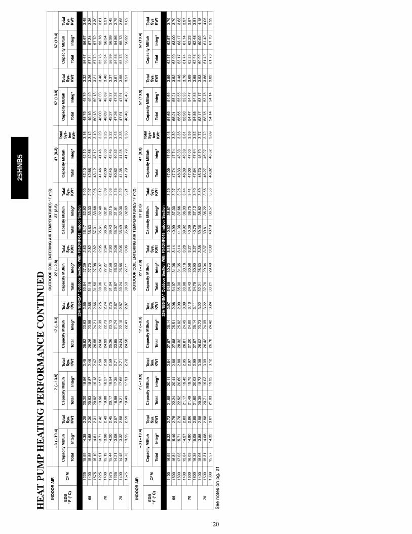
Seenotesonpg.21
25HNB5

19
HEATPUMPHEATINGPERFORMANCECONTINUED
INDOORAIR
OUTDOORCOILENTERINGAIRTEMPERATURES°F(°C)
---3(---19.4)
7(---13.9)
17(---8.3)
27(---2.8)
37(2.8)
47(8.3)
57(13.9)
67(19.4)
EDB
°F(°C)
CFM
CapacityMBtuh
Total
Sys.
KW†
CapacityMBtuh
Total
Sys.
KW†
CapacityMBtuh
Total
Sys.
KW†
CapacityMBtuh
Total
Sys.
KW†
CapacityMBtuh
Total
Sys.
KW†
CapacityMBtuh
Total
Sys-
tem
KW†
CapacityMBtuh
Total
Sys.
KW†
CapacityMBtuh
Total
Sys.
KW†
Total
Integ*
Total
Integ*
Total
Integ*
Total
Integ*
Total
Integ*
Total
Integ*
Total
Integ*
Total
Integ*
25HNB530A**30OutdoorSectionWithFX4DN(B,F)031IndoorSection
65875
9.11
8.38
1.73
12.59
11.57
1.80
16.31
14.87
1.87
20.37
18.09
1.95
25.34
23.06
2.06
29.70
29.70
2.16
34.52
34.52
2.29
39.87
39.87
2.43
1000
9.31
8.57
1.74
12.83
11.79
1.80
16.60
15.13
1.86
20.71
18.40
1.93
25.67
23.36
2.03
30.10
30.10
2.12
35.02
35.02
2.24
40.46
40.46
2.35
1125
9.45
8.69
1.75
13.00
11.95
1.81
16.82
15.34
1.86
21.01
18.66
1.93
25.93
23.59
2.02
30.43
30.43
2.10
35.43
35.43
2.20
40.83
40.83
2.30
70875
8.48
7.80
1.80
11.97
11.00
1.87
15.72
14.33
1.95
19.76
17.55
2.03
24.87
22.63
2.16
29.21
29.21
2.26
33.97
33.97
2.39
39.25
39.25
2.53
1000
8.67
7.97
1.81
12.22
11.23
1.88
16.01
14.60
1.94
20.11
17.86
2.02
25.22
22.95
2.13
29.60
29.60
2.22
34.46
34.46
2.34
39.87
39.87
2.46
1125
8.84
8.13
1.82
12.42
11.41
1.89
16.24
14.81
1.95
20.39
18.11
2.01
25.49
23.20
2.11
29.93
29.93
2.20
34.86
34.86
2.30
40.27
40.27
2.40
75875
7.80
7.18
1.87
11.32
10.40
1.95
15.09
13.76
2.03
19.13
16.99
2.12
23.72
21.59
2.23
28.72
28.72
2.37
33.42
33.42
2.50
38.67
38.67
2.64
1000
7.99
7.35
1.88
11.55
10.62
1.95
15.37
14.02
2.03
19.48
17.30
2.11
24.70
22.48
2.23
29.11
29.11
2.33
33.90
33.90
2.44
39.24
39.24
2.57
1125
8.15
7.50
1.90
11.77
10.81
1.96
15.61
14.24
2.03
19.77
17.56
2.10
25.00
22.75
2.21
29.44
29.44
2.30
34.29
34.29
2.40
39.68
39.68
2.51
INDOORAIR
OUTDOORCOILENTERINGAIRTEMPERATURES°F(°C)
---3(---19.4)
7(---13.9)
17(---8.3)
27(---2.8)
37(2.8)
47(8.3)
57(13.9)
67(19.4)
EDB
°F(°C)
CFM
CapacityMBtuh
Total
Sys.
KW†
CapacityMBtuh
Total
Sys.
KW†
CapacityMBtuh
Total
Sys.
KW†
CapacityMBtuh
Total
Sys.
KW†
CapacityMBtuh
Total
Sys.
KW†
CapacityMBtuh
Total
Sys-
tem
KW†
CapacityMBtuh
Total
Sys.
KW†
CapacityMBtuh
Total
Sys.
KW†
Total
Integ*
Total
Integ*
Total
Integ*
Total
Integ*
Total
Integ*
Total
Integ*
Total
Integ*
Total
Integ*
25HNB536A*OutdoorSectionWithFX4DNF037IndoorSection
651050
11.44
10.52
1.97
15.33
14.09
2.06
19.61
17.88
2.15
24.41
21.68
2.26
29.99
27.29
2.39
35.11
35.11
2.52
40.74
40.74
2.65
46.35
46.35
2.78
1200
11.66
10.73
1.98
15.60
14.34
2.06
19.93
18.17
2.15
24.85
22.07
2.24
30.35
27.62
2.36
35.57
35.57
2.47
41.14
41.14
2.57
46.50
46.50
2.69
1350
11.86
10.91
2.00
15.83
14.55
2.07
20.21
18.42
2.15
25.78
22.90
2.25
30.66
27.90
2.34
35.94
35.94
2.44
41.32
41.32
2.53
46.51
46.51
2.63
701050
10.73
9.87
2.07
14.64
13.45
2.16
18.94
17.26
2.25
23.71
21.05
2.36
29.52
26.86
2.51
34.56
34.56
2.63
40.20
40.20
2.78
45.76
45.76
2.91
1200
10.95
10.08
2.08
14.91
13.70
2.16
19.26
17.56
2.25
24.10
21.41
2.35
29.87
27.19
2.47
35.00
35.00
2.59
40.60
40.60
2.70
45.95
45.95
2.82
1350
11.15
10.26
2.09
15.15
13.92
2.17
19.53
17.81
2.25
24.44
21.70
2.34
30.17
27.46
2.45
35.37
35.37
2.56
40.83
40.83
2.65
46.01
46.01
2.76
751050
9.98
9.19
2.17
13.92
12.79
2.26
18.23
16.62
2.36
22.97
20.40
2.47
28.97
26.36
2.63
34.00
34.00
2.76
39.58
39.58
2.92
45.14
45.14
3.04
1200
10.20
9.38
2.18
14.18
13.03
2.26
18.55
16.92
2.35
23.37
20.76
2.45
29.35
26.71
2.59
34.43
34.43
2.71
40.10
40.10
2.84
45.39
45.39
2.95
1350
10.39
9.55
2.19
14.41
13.25
2.27
18.82
17.16
2.35
23.70
21.05
2.45
29.66
26.99
2.57
34.80
34.80
2.68
40.32
40.32
2.78
45.49
45.49
2.89
Seenotesonpg.21
25HNB5
20
HEATPUMPHEATINGPERFORMANCECONTINUED
INDOORAIR
OUTDOORCOILENTERINGAIRTEMPERATURES°F(°C)
---3(---19.4)
7(---13.9)
17(---8.3)
27(---2.8)
37(2.8)
47(8.3)
57(13.9)
67(19.4)
EDB
°F(°C)
CFM
CapacityMBtuh
Total
Sys.
KW†
CapacityMBtuh
Total
Sys.
KW†
CapacityMBtuh
Total
Sys.
KW†
CapacityMBtuh
Total
Sys.
KW†
CapacityMBtuh
Total
Sys.
KW†
CapacityMBtuh
Total
Sys-
tem
KW†
CapacityMBtuh
Total
Sys.
KW†
CapacityMBtuh
Total
Sys.
KW†
Total
Integ*
Total
Integ*
Total
Integ*
Total
Integ*
Total
Integ*
Total
Integ*
Total
Integ*
Total
Integ*
25HNB542A*OutdoorSectionWithFX4DNF043IndoorSection
651225
15.59
14.35
2.29
20.20
18.56
2.45
25.92
23.63
2.65
30.84
27.39
2.83
36.17
32.92
3.00
42.10
42.10
3.16
48.79
48.79
3.32
56.67
56.67
3.45
1400
15.85
14.58
2.30
20.53
18.87
2.46
26.26
23.95
2.65
31.19
27.70
2.82
36.63
33.33
2.97
42.66
42.66
3.12
49.49
49.49
3.26
57.34
57.34
3.36
1575
16.10
14.81
2.31
20.82
19.13
2.47
26.55
24.21
2.66
31.50
27.98
2.82
37.01
33.68
2.96
43.12
43.12
3.10
50.13
50.13
3.21
57.72
57.72
3.30
701225
14.91
13.71
2.42
19.56
17.97
2.58
24.56
22.39
2.75
30.36
26.97
2.95
35.61
32.40
3.12
41.46
41.46
3.29
48.00
48.00
3.46
55.78
55.78
3.61
1400
15.19
13.98
2.43
19.88
18.27
2.58
24.93
22.73
2.74
30.71
27.27
2.94
36.05
32.81
3.09
42.00
42.00
3.25
48.69
48.69
3.40
56.54
56.54
3.51
1575
15.44
14.20
2.45
20.17
18.54
2.59
25.36
23.13
2.75
31.04
27.56
2.93
36.43
33.15
3.08
42.45
42.45
3.22
49.27
49.27
3.37
56.99
56.99
3.45
751225
14.21
13.08
2.57
18.88
17.35
2.71
23.85
21.74
2.87
29.87
26.53
3.08
35.07
31.91
3.25
40.82
40.82
3.43
47.26
47.26
3.61
54.86
54.86
3.79
1400
14.48
13.32
2.58
19.21
17.65
2.71
24.24
22.10
2.87
30.24
26.86
3.06
35.49
32.30
3.22
41.35
41.35
3.38
47.91
47.91
3.55
55.73
55.73
3.68
1575
14.73
13.55
2.59
19.49
17.91
2.72
24.58
22.41
2.87
30.53
27.11
3.06
35.86
32.63
3.21
41.79
41.79
3.36
48.46
48.46
3.51
56.22
56.22
3.62
INDOORAIR
OUTDOORCOILENTERINGAIRTEMPERATURES°F(°C)
---3(---19.4)
7(---13.9)
17(---8.3)
27(---2.8)
37(2.8)
47(8.3)
57(13.9)
67(19.4)
EDB
°F(°C)
CFM
CapacityMBtuh
Total
Sys.
KW†
CapacityMBtuh
Total
Sys.
KW†
CapacityMBtuh
Total
Sys.
KW†
CapacityMBtuh
Total
Sys.
KW†
CapacityMBtuh
Total
Sys.
KW†
CapacityMBtuh
Total
Sys-
tem
KW†
CapacityMBtuh
Total
Sys.
KW†
CapacityMBtuh
Total
Sys.
KW†
Total
Integ*
Total
Integ*
Total
Integ*
Total
Integ*
Total
Integ*
Total
Integ*
Total
Integ*
Total
Integ*
25HNB548A*OutdoorSectionWithFX4DNF049IndoorSection
651400
16.55
15.22
2.72
21.89
20.11
2.84
27.57
25.14
2.97
34.59
30.72
3.15
40.52
36.87
3.29
47.09
47.09
3.46
54.69
54.69
3.59
62.57
62.57
3.79
1600
16.84
15.49
2.75
22.24
20.44
2.86
27.98
25.51
2.98
34.97
31.06
3.14
40.99
37.30
3.27
47.74
47.74
3.39
55.21
55.21
3.52
63.00
63.00
3.70
1800
17.08
15.71
2.78
22.52
20.69
2.88
28.32
25.82
2.99
35.30
31.35
3.14
41.38
37.66
3.26
48.33
48.33
3.36
55.55
55.55
3.48
63.17
63.17
3.63
701400
15.84
14.57
2.83
21.17
19.45
2.95
26.81
24.45
3.09
33.98
30.18
3.28
39.92
36.33
3.44
46.39
46.39
3.61
53.93
53.93
3.76
61.74
61.74
3.97
1600
16.09
14.80
2.86
21.49
19.75
2.97
27.20
24.80
3.10
34.43
30.58
3.27
40.39
36.75
3.41
47.00
47.00
3.56
54.47
54.47
3.69
62.23
62.23
3.87
1800
16.35
15.05
2.89
21.80
20.03
2.99
27.57
25.14
3.11
34.79
30.90
3.27
40.79
37.12
3.40
47.64
47.64
3.52
54.85
54.85
3.65
62.48
62.48
3.81
751400
15.06
13.85
2.95
20.39
18.73
3.08
26.02
23.73
3.22
32.21
28.60
3.38
39.36
35.82
3.59
45.70
45.70
3.77
53.17
53.17
3.93
60.92
60.92
4.15
1600
15.31
14.08
2.98
20.71
19.03
3.09
26.42
24.09
3.22
32.70
29.04
3.37
39.81
36.22
3.56
46.27
46.27
3.72
53.75
53.75
3.86
61.42
61.42
4.05
1800
15.57
14.32
3.01
21.03
19.32
3.12
26.78
24.42
3.24
33.21
29.49
3.38
40.19
36.57
3.55
46.82
46.82
3.69
54.14
54.14
3.82
61.73
61.73
3.99
Seenotesonpg.21
25HNB5

21
HEATPUMPHEATINGPERFORMANCECONTINUED
INDOORAIR
OUTDOORCOILENTERINGAIRTEMPERATURES°F(°C)
---3(---19.4)
7(---13.9)
17(---8.3)
27(---2.8)
37(2.8)
47(8.3)
57(13.9)
67(19.4)
EDB
°F(°C)
CFM
CapacityMBtuh
Total
Sys.
KW†
CapacityMBtuh
Total
Sys.
KW†
CapacityMBtuh
Total
Sys.
KW†
CapacityMBtuh
Total
Sys.
KW†
CapacityMBtuh
Total
Sys.
KW†
CapacityMBtuh
Total
Sys-
tem
KW†
CapacityMBtuh
Total
Sys.
KW†
CapacityMBtuh
Total
Sys.
KW†
Total
In-
teg*
Total
In-
teg*
Total
In-
teg*
Total
In-
teg*
Total
In-
teg*
Total
In-
teg*
Total
In-
teg*
Total
In-
teg*
25HNB560A*OutdoorSectionWithFX4DNF061IndoorSection
651750
20.88
19.21
3.31
27.26
25.05
3.45
34.02
31.02
3.60
41.60
36.94
3.76
50.26
45.73
3.96
58.37
58.37
4.15
68.00
68.00
4.38
78.95
78.95
4.62
2000
21.30
19.60
3.35
27.75
25.50
3.48
34.60
31.55
3.61
42.46
37.71
3.76
50.83
46.25
3.94
59.12
59.12
4.11
69.17
69.17
4.29
79.81
79.81
4.53
2250
21.68
19.94
3.40
28.17
25.89
3.52
35.08
31.98
3.63
43.85
38.95
3.80
51.36
46.73
3.94
59.75
59.75
4.09
69.90
69.90
4.25
80.36
80.36
4.47
701750
19.82
18.23
3.45
26.24
24.11
3.60
33.08
30.16
3.75
40.53
36.00
3.92
49.53
45.07
4.15
57.50
57.50
4.34
66.89
66.89
4.59
77.83
77.83
4.82
2000
20.23
18.62
3.49
26.72
24.55
3.63
33.63
30.66
3.77
41.18
36.58
3.92
50.11
45.60
4.12
58.23
58.23
4.30
67.91
67.91
4.50
78.70
78.70
4.73
2250
20.61
18.96
3.54
27.14
24.94
3.66
34.10
31.09
3.79
41.75
37.08
3.93
50.63
46.08
4.12
58.85
58.85
4.28
68.90
68.90
4.44
79.31
79.31
4.67
751750
18.71
17.21
3.59
25.18
23.14
3.75
32.07
29.24
3.92
39.48
35.07
4.09
48.83
44.44
4.34
56.65
56.65
4.54
65.78
65.78
4.80
76.71
76.71
5.04
2000
19.12
17.59
3.63
25.65
23.58
3.78
32.61
29.73
3.93
40.11
35.62
4.09
49.43
44.98
4.31
57.38
57.38
4.50
66.86
66.86
4.71
77.61
77.61
4.94
2250
19.49
17.93
3.68
26.08
23.96
3.82
33.08
30.16
3.96
40.67
36.12
4.10
49.89
45.40
4.30
57.98
57.98
4.47
67.79
67.79
4.65
78.22
78.22
4.87
*Testedcombination.
{ThekWvaluesincludethecompressor,outdoorfanmotor,andindoorblowermotor.ThekWfromsupplementheatersshouldbeaddedtothesevaluestoobtaintotalsystemkilowatts.
}TheBtuhheatingcapacityvaluesshownarenetintegratedvaluesfromwhichthedefrosteffecthasbeensubtracted.TheBtuhheatingfromsupplementheatersshouldbeaddedtothosevaluestoobtaintotalsystemcapacity.
NOTE:Whentherequireddatafallsbetweenthepublisheddata,interpolationmaybeperformed.Extrapolationisnotanacceptablepractice.
EDB—EnteringDryBulb
25HNB5

22
GUIDE SPECIFICTIONSGENERALSystem DescriptionOutdoor--mounted, air--cooled, split--system heat pump unitsuitable for ground or rooftop installation. Unit consists of ahermetic compressor, an air--cooled coil, propeller--type condenserfan, and a control box. Unit will discharge supply air upward asshown on contract drawings. Unit will be used in a refrigerationcircuit to match up to a packaged fan coil or coil unit.
Quality Assurance— Unit will be rated in accordance with the latest edition of
AHRI Standard 240.
— Unit will be certified for capacity and efficiency, andlisted in the latest AHRI directory.
— Unit construction will comply with latest edition ofANSI/ ASHRAE and with NEC.
— Unit will be constructed in accordance with ULstandards and will carry the UL label of approval. Unitwill have C--UL approval.
— Unit cabinet will be capable of withstanding Federal TestMethod Standard No. 141 (Method 6061) 500--hr saltspray test.
— Air--cooled condenser coils are pressure tested and theoutdoor units are leak tested.
— Unit constructed in ISO9001 approved facility.
Delivery, Storage, and Handling— Unit will be shipped as single package only and is stored
and handled per unit manufacturer’s recommendations.
Warranty (for inclusion by specifying engineer)— U.S. and Canada only.
PRODUCTSEquipment
— Factory--assembled, single--piece, air--cooled heat pumpunit. Contained within the unit enclosure is all factorywiring, piping, controls, compressor, refrigerant chargePuronr (R--410A), and special features required prior tofield start--up.
Unit Cabinet
— Unit cabinet will be constructed of galvanized steel,bonderized, and coated with a powder coat paint.
Fans
— Condenser fan will be direct--drive propeller type,discharging air upward.
AIR--COOLED, SPLIT--SYSTEM HEAT PUMP25HNB5
1--1/2 TO 5 NOMINAL TONS— Condenser fan motors will be totally enclosed, 1--phase
type with class B insulation and permanently lubricatedbearings.
— Shafts will be corrosion resistant.
— Fan blades will be statically and dynamically balanced.
— Condenser fan openings will be equipped with steel wiresafety guards.
Compressor
— Compressor will be hermetically sealed.
— Compressor will be mounted on rubber vibrationisolators.
Condenser Coil
— Condenser coil will be air cooled.
— Coil will be constructed of aluminum fins mechanicallybonded to copper tubes which are then cleaned,dehydrated, and sealed.
Refrigeration Components
— Refrigeration circuit components will include liquid--lineshutoff valve with sweat connections, vapor--line shutoffvalve with sweat connections, system charge of Puronr(R--410A) refrigerant, POE compressor oil, accumulator,and reversing valve.
Operating Characteristics— The capacity of the unit will meet or exceed _____ Btuh
at a suction temperature of ______F/_C. The powerconsumption at full load will not exceed _____ kW.
— Combination of the unit and the evaporator or fan coilunit will have a total net cooling capacity of _____ Btuhor greater at conditions of _____ CFM entering airtemperature at the evaporator at _____ _F/_C wet bulband _____ _F/_C dry bulb, and air entering the unit at_____ _F/_C.
— The system will have a SEER of _____ Btuh/watt orgreater at DOE conditions.
Electrical Requirements— Nominal unit electrical characteristics will be _____ v,
single phase, 60 hz. The unit will be capable ofsatisfactory operation within voltage limits of _____ v to_____ v.
— Unit electrical power will be single point connection.
— Control circuit will be 24v.
Special Features— Refer to section of this literature identifying accessories
and descriptions for specific features and availableenhancements.
25HNB5

23
SYSTEM DESIGN SUMMARY1. Intended for outdoor installation with free air inlet and outlet. Outdoor fan external static pressure available is less than 0.01--in. wc.
2. Minimum outdoor operating air temperature without low--ambient operation accessory is 55_F (12.8_C).
3. Maximum outdoor operating air temperature for cooling mode is 125_F (51.7_C).
4. Minimum outdoor operating air temperature for heating mode is –30_F (–34.4_C).
5. Maximum outdoor operating air temperature for heating mode is 66_F (18.9_C).
6. For reliable operation, unit should be level in all horizontal planes.
7. For interconnecting refrigerant tube lengths greater than 80 ft (23.4 m) and/or elevation differences between indoor and outdoor unitsgreater than 20 ft (6.1 m), consult Residential Piping and Longline Guideline and Service Manual available from equipmentdistributor.
8. If any refrigerant tubing is buried, provide a 6 in. (152.4 mm) vertical rise to the valve connections at the unit. Refrigerant tubinglengths up to 36 in. (914.4 mm) may be buried without further consideration. Do not bury refrigerant lines longer than 36 in. (914.4mm).
9. Use only copper wire for electric connection at unit. Aluminum and clad aluminum are not acceptable for the type of connectorprovided.
10. Do not apply capillary tube indoor coils to these units.
11. Factory--supplied filter drier must be installed.
25HNB5
24
Copyright 2017 Carrier Corp. D 7310 W. Morris St. D Indianapolis, IN 46231 Edition Date: 06/17
Manufacturer reserves the right to change, at any time, specifications and designs without notice and without obligations.
Catalog No: 25HNB5---5PD
Replaces: 25HNB5---4PD
25HNB5