product data: miniature deltatron® accelerometer — type
TRANSCRIPT
4397A/–8A/–9A
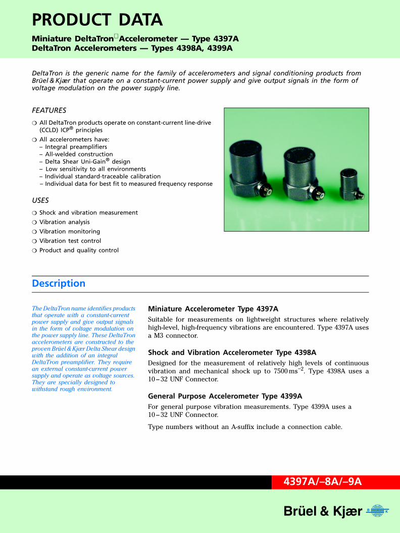
PRODUCT DATAMiniature DeltaTronAccelerometer — Type 4397ADeltaTron Accelerometers — Types 4398A, 4399A
DeltaTron is the generic name for the family of accelerometers and signal conditioning products from Brüel & Kjær that operate on a constant-current power supply and give output signals in the form of voltage modulation on the power supply line.
FEATURES
All DeltaTron products operate on constant-current line-drive (CCLD) ICP® principles
All accelerometers have:– Integral preamplifiers– All-welded construction– Delta Shear Uni-Gain® design– Low sensitivity to all environments– Individual standard-traceable calibration– Individual data for best fit to measured frequency response
USES
Shock and vibration measurement
Vibration analysis
Vibration monitoring
Vibration test control
Product and quality control
Description
The DeltaTron name identifies products that operate with a constant-current power supply and give output signals in the form of voltage modulation on the power supply line. These DeltaTron
accelerometers are constructed to the proven Brüel & Kjær Delta Shear design with the addition of an integral DeltaTron preamplifier. They require an external constant-current power supply and operate as voltage sources. They are specially designed to withstand rough environment.
Miniature Accelerometer Type 4397ASuitable for measurements on lightweight structures where relativelyhigh-level, high-frequency vibrations are encountered. Type 4397A usesa M3 connector.
Shock and Vibration Accelerometer Type 4398ADesigned for the measurement of relatively high levels of continuousvibration and mechanical shock up to 7500 ms−2. Type 4398A uses a10 – 32 UNF Connector.
General Purpose Accelerometer Type 4399AFor general purpose vibration measurements. Type 4399A uses a10 – 32 UNF Connector.
Type numbers without an A-suffix include a connection cable.
Design
DeltaShear® design
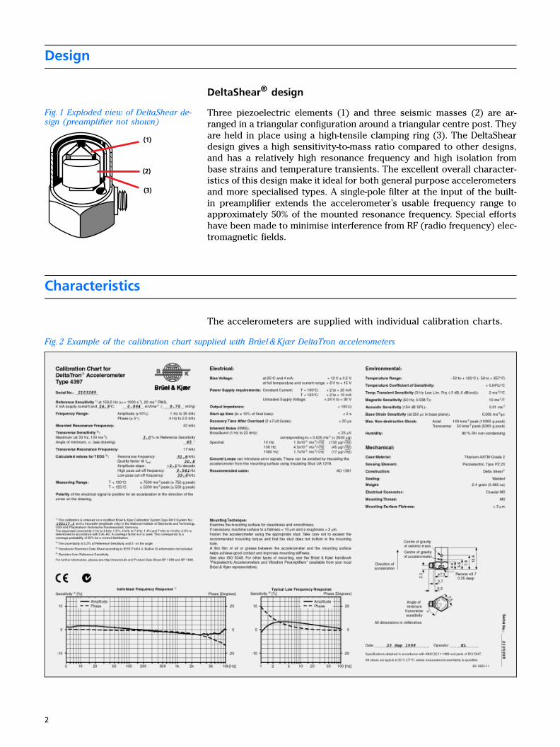
Fig. 1 Exploded view of DeltaShear de-sign (preamplifier not shown)
Three piezoelectric elements (1) and three seismic masses (2) are ar-ranged in a triangular configuration around a triangular centre post. Theyare held in place using a high-tensile clamping ring (3). The DeltaSheardesign gives a high sensitivity-to-mass ratio compared to other designs,and has a relatively high resonance frequency and high isolation frombase strains and temperature transients. The excellent overall character-istics of this design make it ideal for both general purpose accelerometersand more specialised types. A single-pole filter at the input of the built-in preamplifier extends the accelerometer’s usable frequency range toapproximately 50% of the mounted resonance frequency. Special effortshave been made to minimise interference from RF (radio frequency) elec-tromagnetic fields.
Characteristics
The accelerometers are supplied with individual calibration charts.
Fig. 2 Example of the calibration chart supplied with Brüel & Kjær DeltaTron accelerometers
(1)
(2)
(3)
2
Uni-Gain SensitivityThe Brüel & Kjær Uni-Gain design means that the accelerometer sensi-tivity is adjusted during manufacture to within 2% of either 1 or 10 mV/ms−2.
Frequency ResponseThe upper frequency limits given in the specifications are the frequen-cies where the deviation from the reference sensitivity is less than 10%.It is approximately 50% of the mounted resonance frequency. This as-sumes that the accelerometer is correctly mounted onto the test struc-ture – a poor mounting can have a marked effect on the mountedresonance frequency.
The lower frequency limits and phase response are determined by thebuilt-in preamplifiers. The lower frequency limits are given in the spec-ifications for deviations from reference sensitivity of less than 10%.
Increased measurement accuracy can be achieved by dividing the actualmeasurement with the individual frequency response.
Individually measured frequency response curves
The frequency response curves given on the calibration chart are indi-vidually measured over most of the frequency range. At low frequencies,the curves given are typical (Fig. 2).
Individual data for best-fit to measured frequency response
The calibration chart also includes individual data that, together witha general formula, best fits the measured frequency response. The ex-pression can be used for frequency response compensation in the spec-ified frequency range. The relative frequency response includingamplitude and phase is:
Sign = Polarity
b = Temperature coefficient
T = Temperature
Tref = Reference temperature
f = Frequency
fhp = High-pass cut-off frequency
flp = Low-pass cut-off frequency
fres = Resonance frequency
fref = Reference frequency
Q = Quality factor
a = Amplitude slope/decade
Combining this equation with the amplitude sensitivity Sref and fref andTref we have:
Implementation of this formula in either real-time data acquisition sys-tems or in post-processing will support automatic update of amplitudeand/or phase.
Srel f T,( ) Sign( )(1 b T Tref–( )+ )
j ffhp--------
1 j+f
fhp--------
--------------------------× 1
1 j fflp-------+
------------------------× × 1
1 + j ffres---------
+j fQfres---------------
2
--------------------------------------------------------× j f
fref---------
a10ln
------------
=
S f T,( ) Sref=Srel f T,( )
Srel frefTref( )--------------------------------------×
3

Transverse SensitivityThe direction of minimum transverse sensitivity is indicated on the calibration chart of each DeltaTron
accelerometer.
All piezoelectric accelerometers are slightly sensitive to accelerationperpendicular to their main sensitivity axis. This transverse sensitivityis measured during factory calibration using 30 Hz and 100 ms−2 excita-tion, and is given as a percentage of the corresponding main axis sen-sitivity.
Transverse Resonance FrequencyTypical values for the transverse resonance frequency are obtained bymounting an accelerometer on the side of a steel cube attached to aCalibration Exciter Type 4290.
Dynamic RangeThe dynamic range of an accelerometer is the range over which its electrical output is directly proportional to the acceleration applied to its base.
Upper Limit
In general, the smaller the accelerometer, the higher the vibration levelat which it can be used. The upper limit depends on the type of vibrationto which the accelerometer is subjected and is determined by the pre-stressing of the piezoelectric elements as well as by the mechanicalstrength of the element.
The acceleration ranges given in the specifications are determined bythe measuring limits of the integral preamplifiers. For transporting andhandling, the maximum non-destructive shock is given.
When short duration transient signals are measured, care must be takento avoid ringing effects due to the high-frequency resonance of theaccelerometer. As a general rule, the duration of a half sine shock pulseshould be greater than 5/fR for an amplitude error of less than 10%,where fR is the mounted resonance frequency of the accelerometer.
Lower Limit
The lower limit is imposed by the noise level of the integral preamplifier,which has been constructed to give very low noise levels, and by theenvironment in which the measurements are made.
Electrical ImpedanceAll DeltaTron accelerometers have integral preamplifiers and can beregarded as voltage sources. The output impedance is typically lessthan 100 Ω. With a supply current of >4 mA, the output impedance istypically less than <30 Ω.
Environment
A discussion of the effect of environmental influences, can be found in the Brüel & Kjær handbook “Piezoelectric Accelerometers and Vibration Preamplifiers”.
TemperatureDeltaTron accelerometers have an operating temperature range of −50°Cto +125°C. Throughout this range, the sensitivity of the accelerometershas a small temperature dependence, details of which are given on theindividual calibration charts (see Fig. 2).
Temperature TransientsThe procedure for measuring temperature transient sensitivity is also described in the handbook.
All piezoelectric accelerometers have slight sensitivity to temperaturefluctuations. This effect may be significant when low frequency, lowlevel acceleration is being measured.
4

HumidityDeltaTron accelerometers have all-welded titanium housings to givethem a high resistance to the majority of corrosive agents found inindustry. The low impedance of the preamplifier gives it a low sensitivityto humidity on the output terminal and allows the accelerometers tobe used without protection in conditions where there is a small amountof condensation.
Where heavy condensation is encountered, the use of moisture imper-vious cables and sealing will permit operation. Suitable sealants areDow Corning’s RTV 738 or similar compounds.
Sound PressureThe acoustic sensitivity is low, and can be neglected for most vibrationmeasurements. The vibration signal from the structure under test isnormally much greater than the signal due to acoustic sensitivity.
Acoustic sensitivity is specified as an equivalent acceleration causedby a 154 dB sound pressure level in the frequency range 2 Hz to 100 Hz,but the specified value is normally valid outside this range.
Electromagnetic Compatibility (EMC)Susceptibility of DeltaTron
accelerometers to radio-frequency electromagnetic radiation is also low.
The accelerometers comply with Standards EN 50081–1 and EN 50082–2for emission and immunity, respectively.
Base StrainBase strains can be introduced into an accelerometer by distortion of the surface to which it is attached.
Base strain sensitivity, which is minimised by the Delta Shear construc-tion, is specified in ms−2/µε.
Connecting Cables
For direct connection to DeltaTron accelerometers, miniature, double-screened, low-noise, single-core, coaxial cables are available.
Type 4397A requires cables with an M3 connector while Types 4398Aand 4399A require cables with 10 – 32 UNF connectors. See Optional andAdditional Accessories, the Transducer & Conditioning Catalogue(BF 0189) and Sound & Vibration Catalogue (BF 0201) for additional cablelengths and connectors.
Note, however, that for many non-critical applications, lower qualitycables or twisted pairs can be used. However, when such cables areused, the EMC certification is not valid.
Details of the accelerometer connections and recommended plug clear-ances are given in the section entitled Accelerometer Dimensions.
Maximum Cable Length
The maximum output voltage of a DeltaTron accelerometer depends onthe supply current at which it is operating, and on the capacitive loaddue to the connecting cable.
Fig. 3 shows typical curves for maximum output levels with supplycurrents of 2 and 20 mA (for distortion ≤1%).
The maximum cable length in metres is given by:
L 75000Is
f Vo Cm××------------------------------×=
5

where
Is = supply current [mA]
f = frequency [kHz]
Vo = output voltage [Vpeak]
Cm = cable capacitance [pF/m]
If the supply current is less than 4 mA, the power consumption of thebuilt-in preamplifier becomes significant and this formula cannot beapplied.
Fig. 3 Typical curves for maximum out-put level of DeltaTron accelerometers, showing maximum capacitive load over the recommended current supply range
Mounting
Brüel & Kjær accelerometers can be mounted with their main sensitivityaxis aligned in any direction.
Recommended Mounting Technique
Fig. 4 Recommended mounting tech-nique for Type 4397A using Steel Stud YS 8321 and for Types 4398A/–9A using Steel Stud YG 0150
Fig. 4 shows the recommendedmounting method for these accel-erometers. The accelerometersare screwed onto a clean metalsurface using a threaded steelstud and meet the requirementsspecified in Fig. 5.
920731e
1 2 3 4 5 6 7 8 9 10 20Frequency [kHz]
Max
imum
Out
put [
V] P
eak
1
2
3
4
5
6
7
8
9
50nF
500nF
2mA
20nF
2mA
2nF
2mA
1nF
2mA
10nF
2mA
5nF
2mA
20mA
20mA
50nF
20mA
20nF
20mA
10nF
20mA
200nF
20mA
100nF
20mA
1µF
930398e
6

Fig. 5 Recommended tolerances for the mounting surfaces. Dimensions and symbols are in accordance with ISO 1101
Under normal circumstances the absolute minimum depth of 4 mm isnot sufficient to accommodate the mounting stud, but is the minimumdepth required to hold a stud securely. The optimum torque for tight-ening 10 – 32UNF steel studs is 0.5 – 3.5 Nm, for M3 steel studs it is0.2 – 0.6 Nm. The required tolerances on the clean metal mountingsurface are shown in Fig. 5.
When using the recommended technique, note that if the mountingsurface is not perfectly smooth, applying a thin layer of grease to thebase of the accelerometer before screwing it into the mounting surfacewill improve the mounting stiffness.
Alternative Mounting TechniquesWhen mounting techniques other than the recommended technique areused, the accelerometer mounted resonance frequency will probably belower.
Fig. 6 Alternative mounting techniques
Fig. 6 shows some alternative mounting techniques. The section entitledAccessories Included lists the mounting accessories supplied with theindividual accelerometer types. These mounting techniques are de-scribed in detail in Brüel & Kjær’s “Piezoelectric Accelerometers andVibration Preamplifiers” handbook (BB 0694), which illustrates the ef-fects of the different methods on the frequency response curve of anaccelerometer.
A
AØ 0.0210 - 32 UNF
or M3
0.01
1.60.25
AbsoluteMin. Depth.
4 mm
7
Calibration
Factory CalibrationAll Brüel & Kjær accelerometers are thoroughly checked and examined at each stage of manufacture and assembly. Each accelerometer undergoes an extensive calibration procedure and artificial ageing process to ensure completely predictable performance and stable operation. Accurate numerical details of the calibration are reported on the calibration chart supplied with each transducer (see Fig. 2).
At Brüel & Kjær, piezoelectric accelerometers are calibrated by back-to-back comparison with a primary reference standard accelerometerwhich is regularly calibrated by laser interferometry at the Danish Pri-mary Laboratory of Acoustics and by both the American National Insti-tute of Standards and Technology and the German Physikalisch –Technische Bundesanstalt. The overall accuracy of the back-to-backcomparison is ±2% with a 99.9% confidence level (±1.6% for a 99%confidence level), while for the interferometry method the accuracy isbetter than ± 0.6% with a 99% confidence level.
Subsequent CalibrationRegular calibration of accelerometers helps maintain confidence in themeasurements taken and indicates whether accelerometers have beendamaged. Brüel & Kjær offers a factory Standard Calibration as a re-calibration service including a new calibration chart (see Ordering In-formation). Brüel & Kjær manufactures a range of equipment for frequen-cy response, sensitivity and system calibrations, details of which areavailable in separate Product Data.
Compliance with Standards
,
CE-mark indicates compliance with: EMC Directive and Low Voltage Directive.C-Tick mark indicates compliance with the EMC requirements of Australia and New Zealand
Safety EN 61010–1 and IEC 61010–1: Safety requirements for electrical equipment for measurement, control and laboratory use.UL 3111–1: Standard for Safety – Electrical measuring and test equipment
EMC Emission EN 50081–1: Generic emission standard. Part 1: Residential, commercial and light industry.EN 50081–2: Generic emission standard. Part 2: Industrial environment.CISPR 22: Radio disturbance characteristics of information technology equipment. Class B Limits.FCC Rules, Part 15: Complies with the limits for a Class B digital device.
EMC Immunity EN 50082–1: Generic immunity standard. Part 1: Residential, commercial and light industry.EN 50082–2: Generic immunity standard. Part 2: Industrial environment. Note 1: The above is guaranteed using optional accessories listed in this Product Data sheet only.Note 2: The above is guaranteed only when the AC output is not in use.
Temperature IEC 68–2–1 & IEC 68–2–2: Environmental Testing. Cold and Dry Heat.Operating Temperature: –50 to +125°C (–58 to +257°F)
Humidity IEC 68–2–3: Damp Heat: 90% RH (non-condensing at 40°C (104°F)
8

Accessories Included
Optional Accessories
Part Number 4397A 4398A 4399A
YS 8321 Steel Stud M3/M3 (UA 1221 is a set of 25 of these studs) x
YG 0150 Steel Stud 10 – 32 UNF/10 – 32 UNF x x
BC 0325 Individual Calibration Chart x
BC 0326 Individual Calibration Chart x
BC 0327 Individual Calibration Chart x
Part Number 4397A 4398A 4399A
AO 1381*
*The EMC certification is only valid for AO 1381 and AO 1382
Teflon Low-noise Cable, double screened AC 0104 (∅ 1.6 mm).Fitted with one 10–32 UNF and one M3 connector. Length 1.2 m
x
AO 1382* Teflon Low-noise Cable, double screened AC 0104 (∅ 1.6 mm).Fitted with two 10–32 UNF connectors. Length 1.2 m
x x
JJ 0032 Extension Connector for cables fitted with 10–32 UNF connectors x x x
JP 0145 10–32 UNF to BNC Adaptor x x x
YS 8321 Steel Stud M3/M3 (UA 1221 is a set of 25 of these studs) x
YQ 2003 Steel Stud M3, 5 mm long x
YG 0150 Steel Stud 10 – 32 UNF/10 – 32 UNF x x
YQ 2960 10–32 UNF Threaded Steel Stud. Length 0.5 in. x x
YQ 2962 10–32 UNF Threaded Steel Stud. Length 0.3 in. x x
YM 0414 10–32 UNF Nut x x
QA 0041 Tap for M3 Thread x
QA 0029 Tap for 10–32 UNF Thread x x
DB 0757 Cement Stud M3. Diameter 8 mm x
DB 0756 Cement Stud 10–32 UNF. Diameter 14 mm x x
QA 0042 Hexagonal Key for M3 studs x
QA 0013 Hexagonal Key for 10–32 UNF studs x x
YJ 0216 Beeswax for mounting x x x
UA 0642 Mounting Magnet with 10–32 UNF stud x x
YO 0073 25 × Adhesive Mounting Discs. Diameter 5.5 mm x
QS 0007 Tube of Cyanoacrylate Adhesive x x x
UA 1218 Standard Accessory Set x
UA 1219 Standard Accessory Set x x
WB 1372 DeltaTron Power Supply x x x
ZG 0328 Power Supply Adaptor x x x
9
Additional Accessories
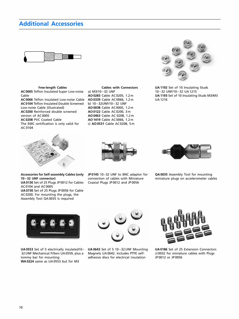
Free-length CablesAC 0005 Teflon Insulated Super Low-noise CableAC 0066 Teflon Insulated Low-noise CableAC 0104 Teflon Insulated Double Screened Low-noise Cable (illustrated)AC 0200 Reinforced double screened version of AC 0005AC 0208 PVC Coated CableThe EMC certification is only valid for AC 0104
Cables with Connectorsa) M3/10 – 32 UNFAO 0283 Cable AC 0205, 1.2 mAO 0339 Cable AC 0066, 1.2 mb) 10 – 32UNF/10 – 32 UNFAO 0038 Cable AC 0005, 1.2 mAO 0122 Cable AC 0200, 3 mAO 0463 Cable AC 0208, 1.2 mAO 1419 Cable AC 0066, 1.2 mc) AO 0531 Cable AC 0208, 5 m
UA 1192 Set of 10 Insulating Studs 10 – 32 UNF/10 – 32 UA 1215UA 1193 Set of 10 Insulating Studs M3/M3 UA 1216
Accessories for Self-assembly Cables (only 10 – 32 UNF connector)UA 0130 Set of 25 Plugs JP 0012 for Cables AC 0104 and AC 0005UA 0730 Set of 25 Plugs JP 0056 for Cable AC 0200. For mounting the plugs, the Assembly Tool QA 0035 is required
JP 0145 10–32 UNF to BNC adaptor for connection of cables with Miniature Coaxial Plugs JP 0012 and JP 0056
QA 0035 Assembly Tool for mounting miniature plugs on accelerometer cables
UA 0553 Set of 5 electrically insulated10 –32 UNF Mechanical Filters UA 0559, plus a tommy bar for mountingWA 0224 same as UA 0553 but for M3
UA 0643 Set of 5 10 – 32 UNF Mounting Magnets UA 0642. Includes PTFE self-adhesive discs for electrical insulation
UA 0186 Set of 25 Extension Connectors JJ 0032 for miniature cables with Plugs JP 0012 or JP 0056
10

Accelerometer Dimensions
Fig. 7 Accelerometer dimensions – shown full scale, all dimensions in mm
UA 0866 Set of 25 10–32 UNF Cement Studs DB 0756UA 0867 Set of 25 M3 Cement Studs DB 0757
UA 1221 Set of 25 Steel Studs M3/M3 with Flange YS 8321
UA 0125 Set of 10 Insulating Studs YP 0150, 10 Steel Studs YQ 2960, 10 Nuts YM 0414, 10 Mica Washers YO 0534 plus 10–32 UNF tap and hexagonal key for 10–32 UNF studs
930058e
Type 4397A
7.3 dia
Spanner size 7.5across flats
Recess 3.7 dia.0.35 deep
Fastening ThreadM3. Depth 2.4
Subminiature coaxialconnector M3
Recommendedclearance for
plug 18.0
7.3 dia
0.7
4.4
2.3
5.6 7
.9 12
.4
2.5
g x
sm o
13.5 dia
7.2
13.5 dia5.5
2.0
3.7
Miniature coaxconnector.
Thread10-32 UNF-2A
8.9 12
.4 19.7
Recess 6.5 dia.0.5 deep
FasteningThread10-32UNF-2BDepth 3.2
Recommendedclearance for plug
15.0. AbsoluteMinimum 12.0
Spanner size14.0 acrossflats
Type 4398A
930057e
sm o
g x
14.0 dia
7.3
14.0 dia5.5
2.0
3.8
Miniature coaxconnector.
Thread10-32 UNF-2A
9.9 12
.8
21.7
FasteningThread 10-32UNF-2Depth 3.2
Recommendedclearance for plug
15.0. AbsoluteMinimum 11.0
Spanner size15.0 acrossflats
Type 4399A
930056e
Recess 6.5 dia.0.5 deep
g x
sm o
11

12
Specifications
Dynamic
Type 4397A Type 4398A Type 4399A
Mounted Resonance Frequency, typical kHz 53 38 29
Transverse Resonance Frequency, typical kHz 17 14 10
Sensitivity (axial) at 159.2 Hz, 100 ms–2 (10.2 g), 25°C (77°F), 4 mA mV/ms–2 (/g) 1.00 (9.807) ±2 % 10.0 (98.07) ± 2 %
Measuring Range (peak), typical temperature <100°C (212°F) ms–2 (g) ±7500 (765) ±750 (76)
temperature <125°C (257°F) ms–2 (g) ±5000 (510) ±500 (51)
Frequency Range (±10%), typical.* Hz 1 to 25000 0.3 to 18000 1 to 14000
Maximum Transverse Response % < 4
*Note: The frequency range from 5 Hz to 10 kHz is measured individually and shown on the calibration chart supplied. The expanded uncertainty 5 Hz to 4 kHz: 1.0%, 4 kHz to 7 kHz: 1.4% and 7 kHz to 10 kHz: 2% is determined in accordance with EAL-RZ. A coverage factor k = 2 is used. This corresponds to a coverage probability of 95% for a normal distribution.
Electrical
Constant Current Supply temperature <100°C (212°F) mA +2 to +20
temperature <125°C (257°F) mA +2 to +10 +2 to +20
Supply Voltage, unloaded for full specification V DC +24 to +30
minimum (reduced specification) V DC +18
Output Impedance Ω <100
Bias Voltage at 25°C (77°F), 4 mA V 12 ±0.5
full temperature and current range V 8 to 15
Residual Noise, typical from 1 to 22000 Hz µV <25 <15 <40
equivalent acceleration ms–2 (g) <0.025 (0.0026) <0.015 (0.0015) <0.004 (0.0004)
Polarity (acceleration directed from base into body) Positive
Recovery time from Overload (2 × maximum level) µs <20 <15 <25
Environmental
Base Strain Sensitivity, typical ms−2 (g)/µε 0.005 (0.0005) 0.02 (0.002) 0.01 (0.001)
Maximum Non-destructive Shock (peak)
Axial ms–2 (g) 100000 (10200) 50000 (5100) 20000 (2040)
Transverse ms–2 (g) 50000 (5100) 20000 (2040) 10000 (1020)
Temperature Range °C (°F) –50 to +125 (–58 to +257)
Humidity Welded, sealed
Temperature Transient Sensitivity, typical ms–2/°C(g/°F)
2 (0.1) 0.2 (0.01) 0.1 (0.006)
Magnetic Sensitivity (50 Hz, 0.038T), typical ms–2(g)/ T 10 (1) 20 (2) 5 (0.5)
Acoustic Sensitivity (154 dB SPL), typical ms–2 (g) 0.01 (0.001) 0.005 (0.0005) 0.002 (0.0002)
Physical
Weight gram (oz.) 2.4 (0.09) 11.8 (0.42) 17.1 (0.60)
Height mm (in) 12.4 (0.49) 19.7 (0.77) 21.7 (0.85)
Spanner Size mm (in) 7.5 (0.30) 14.0 (0.55) 15.0 (0.59)
Construction Delta Shear
Piezoelectric Material PZ 23
Case Material Titanium ASTM Gr. 2
Connector Coaxial M3 miniature 10 – 32 UNF
Mounting Thread Tapped centre hole M3 10 – 32 UNF
Mounting Torque Nm (lb.in) 0.2 to 0.6(1.8 to 5.3)
0.5 to 3.5 (4.4 to 31)

BP
1849
–11
99/0
8
HEADQUARTERS: DK-2850 Nærum · Denmark · Telephone: +4545800500 · Fax: +4545801405 · http://www.bk.dk · e-mail: [email protected] (02)9450-2066 · Austria 0043-1-8657400 · Brazil (011)5182-8166 · Canada (514)695-8225 · China (86) 1068029906Czech Republic 02-67021100 · Finland (0)9-755 950 · France (01)69906900 · Germany 06103/908-5 6 · Hong Kong 25487486 · Hungary (1)2158305Ireland (01) 450 4922 · Italy (02)57604141 · Japan 03-3779-8671 · Republic of Korea (02)3473-0605 · Netherlands (0)30 6039994 · Norway 66771155Poland (22)858 9392 · Portugal (1)4711453 · Singapore (65) 377- 4512 · Slovak Republic 421 7 544 307 01 · Spain (91)3681000 · Sweden (08)4498600 Switzerland 01/9436070 · Taiwan (02)7139303 · United Kingdom (0181)954-2366 · USA 18003322040 Local representatives and service organisations worldwide
Brüel & Kjær reserves the right to change specifications and accessories without notice
Ordering InformationType 4397A Miniature DeltaTron AccelerometerTypes 4398A, 4399A DeltaTron AccelerometersSee tables for Included, Optional and Additional Accessories
4397 – CFF Re-calibration4398 – CFF Re-calibration4399 – CFF Re-calibration