product data sheet - mts sensors · mts sensors r-series models rp and rh temposonics®...
TRANSCRIPT
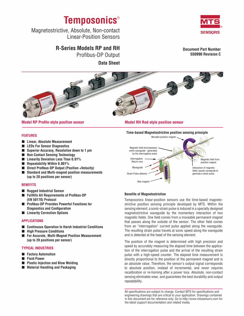
Model RH Rod-style position sensorModel RP Profile-style position sensor
All specifications are subject to change. Contact MTS for specifications and engineering drawings that are critical to your application. Drawings contained in this document are for reference only. Go to http://www.mtssensors.com for the latest support documentation and related media.
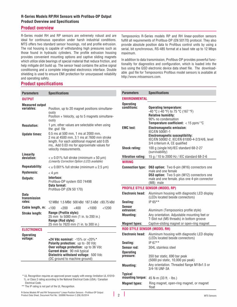
Time-based Magnetostrictive position sensing principleMovable position magnet
Magnetic field from position magnet
Interaction of magnetic fields causes waveguide to generate a strain pulse
Magnetic field encompassesentire waveguide - generated
by the interrogation pulse
Bias magnet
Strain-Pulse detector
InterrogationReturn wire
Waveguide
Benefits of Magnetostriction
Temposonics linear-position sensors use the time-based magneto- strictive position sensing principle developed by MTS. Within the sensing element, a sonic-strain pulse is induced in a specially designed magnetostrictive waveguide by the momentary interaction of two magnetic fields. One field comes from a moveable permanent magnet that passes along the outside of the sensor. The other field comes from an “interrogation” current pulse applied along the waveguide. The resulting strain pulse travels at sonic speed along the waveguide and is detected at the head of the sensing element.
The position of the magnet is determined with high precision and speed by accurately measuring the elapsed time between the applica-tion of the interrogation pulse and the arrival of the resulting strain pulse with a high-speed counter. The elapsed time measurement is directly proportional to the position of the permanent magnet and is an absolute value. Therefore, the sensor's output signal corresponds to absolute position, instead of incremental, and never requires recalibration or re-homing after a power loss. Absolute, non-contact sensing eliminates wear, and guarantees the best durability and output repeatability.
Temposonics®
Magnetostrictive, Absolute, Non-contact
Linear-Position Sensors
R-Series Models RP and RHProfibus-DP Output
Data Sheet
SENSORS
®
Document Part Number 550990 Revision C
FEATURES
� Linear, Absolute Measurement � LEDs For Sensor Diagnostics � Superior Accuracy, Resolution down to 1 µm � Non-Contact Sensing Technology � Linearity Deviation Less Than 0.01% � Repeatability Within 0.001% � Direct Profibus-DP Output (Position +Velocity) � Standard and Multi-magnet position measurements
(up to 20 positions per sensor)
BENEFITS
� Rugged Industrial Sensor � Fullfills All Requirements of Profibus-DP
(EN 50170) Protocol � Profibus-DP Provides Powerful Functions for
Diagnostics and Configuration � Linearity Correction Options
APPLICATIONS
� Continuous Operation In Harsh Industrial Conditions � High Pressure Conditions � For Accurate, Multi-Magnet Position Measurement
(up to 20 positions per sensor)
TYPICAL INDUSTRIES
� Factory Automation � Fluid Power � Plastic Injection and Blow Molding � Material Handling and Packaging
MTS SensorsR-Series Models RP and RH Temposonics® Linear-Position Sensors - Profibus-DP OutputProduct Data Sheet, Document Part No.: 550990 Revision C (EN) 05/2014 2
Product specifications
Product overview
Parameters Specifications
OUTPUT
Measured output variables: Position, up to 20 magnet positions simultane-
ouslyPosition + Velocity, up to 5 magnets simultane-ously
Resolution: 1 µm, other values are selectable when using the .gsd file
Update times: 0.5 ms at 500 mm, 1 ms at 2000 mm, 2 ms at 4500 mm, 3.1 ms at 7600 mm stroke length. For each additional magnet add 0.05 ms,. Add 0.03 ms for approximate values for velocity measurements.
Linearity deviation: < ± 0.01% full stroke (minimum ± 50 µm)
(Linearity Correction Option (LCO) available)
Repeatability: < ± 0.001% full stroke (minimum ± 2.5 µm)Hysteresis: < 4 µmOutputs: Interface:
Profibus-DP system ISO 74498Data format: Profibus-DP (EN 50 170)
Data transmission rates: 12 MBd 1.5 MBd 500 kBd 187.5 kBd ≤93.75 kBdCable length, m: <100 <200 <400 <1000 <1200Stroke length: Range (Profile style):
25 mm to 5080 mm (1 in. to 200 in.)Range (Rod style): 25 mm to 7620 mm (1 in. to 300 in.)
ELECTRONICSOperatingvoltage: +24 Vdc nominal: -15% or +20%*
Polarity protection: up to -30 VdcOver voltage protection: up to 36 VdcCurrent drain: 90 mA typicalDielectric withstand voltage: 500 Vdc(DC ground to machine ground)
R-Series Models RP/RH Sensors with Profibus-DP Output Product Overview and Specifications
Parameters Specifications
ENVIRONMENTALOperating conditions: Operating temperature:
-40 °C (-40 °F) to 75 °C (167 °F)Relative humidity: 90% no condensationTemperature coefficient: < 15 ppm/ °C
EMC test: Electromagnetic emission: IEC/EN 50081-1Electromagnetic susceptibility: IEC/EN 50082-2, IEC/EN 61000-4-2/3/4/6, level 3/4 criterium A, CE qualified
Shock rating: 100 g (single hit)/IEC standard 68-2-27 (survivability)
Vibration rating: 15 g / 10 to 2000 Hz / IEC standard 68-2-6WIRINGConnection type: D63 option: Two 6-pin (M16) connectors one
male and one female D53 option: Two 5-pin (M12) connectors one male and one female. plus one 4-pin connector (M8) male
PROFILE STYLE SENSOR (MODEL RP)Electronic head: Aluminum housing with diagnostic LED display
(LEDs located beside connectors)Sealing: IP 65**Sensor extrusion: Aluminum (Temposonics profile style)Mounting: Any orientation. Adjustable mounting feet or
T-Slot nut (M5 threads) in bottom grooveMagnet types: Captive-sliding magnet or open-ring magnetROD STYLE SENSOR (MODEL RH)Electronic head: Aluminum housing with diagnostic LED display
(LEDs located beside connectors)Sealing: IP 67**Sensor rod: 304L stainless steelOperating pressure: 350 bar static, 690 bar peak
(5000 psi static, 10,000 psi peak) Mounting: Any orientation. Threaded flange M18x1.5 or
3/4-16 UNF-3ATypicalmounting torque: 45 N-m (33 ft. - lbs.)Magnet types: Ring magnet, open-ring magnet, or magnet
float
R-Series model RH and RP sensors are extremely robust and are ideal for continuous operation under harsh industrial conditions. MTS offers two standard sensor housings, rod and profile extrusion. The rod housing is capable of withstanding high pressures such as those found in hydraulic cylinders. The profile extrusion housing provides convenient mounting options and captive sliding magnets which utilize slide bearings of special material that reduce friction, and help mitigate dirt build up. The sensor head contains the active signal conditioning and a complete integrated electronics interface. Double shielding is used to ensure EMI protection for unsurpassed reliability and operating safety.
Temposonics R-Series models RP and RH linear-position sensors fulfill all requirements of Profibus-DP (EN 50170) protocol. They also provide absolute position data to Profibus control units by using a serial, bit synchronous, RS-485 format at a baud rate up to 12 Mbps maximum.
In addition to data transmission, Profibus-DP provides powerful func-tionality for diagnostics and configuration, which is loaded into the bus using the GSD electronic device data sheet file. The download-able .gsd file for Temposonics Profibus model sensors is available at http://www.mtssensors.com.
* UL Recognition requires an approved power supply with energy limitation UL 61010- 1), or Class 2 rating according to the National Electrical Code (USA) / Canadian Electrical Code. ** The IP rating is not part of the UL Recognition.
MTS SensorsR-Series Models RP and RH Temposonics® Linear-Position Sensors - Profibus-DP Output
Product Data Sheet, Document Part No.: 550990 Revision C (EN) 05/20143
R-Series Models RP/RH Sensors with Profibus-DP OutputEnhanced Monitoring and Diagnostics, Output Parameters
Enhanced monitoring and diagnostics
SENSOR STATUS AND DIAGNOSTIC DISPLAY
Integrated diagnostic LEDs (green/red), located beside sensor con-nectors (see ‘Figure 1’), provide basic visual monitoring for normal sensor operation and troubleshooting. diagnostic display LEDs indicate four modes described in ‘Table 1’.
Figure 1. R-Series sensor Integrated diagnostic LEDs
Profibus-DP output parameters
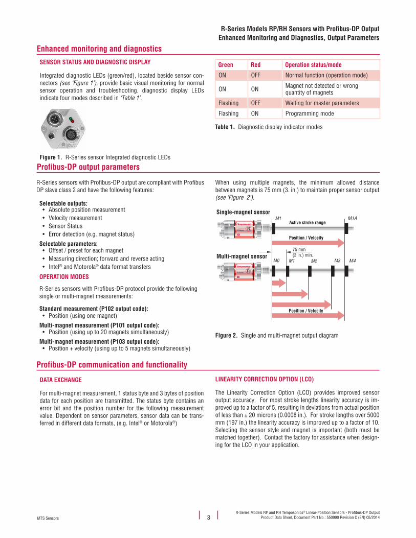
When using multiple magnets, the minimum allowed distance between magnets is 75 mm (3. in.) to maintain proper sensor output (see ‘Figure 2’).
Figure 2.
Temposonics®
R-Series R®
Single-magnet sensor
Multi-magnet sensor
M1 M1AActive stroke range
Position / Velocity
M0 M1 M3 M4
Position / Velocity
75 mm(3 in.) min.
M2Temposonics®
R-Series R®
Single and multi-magnet output diagram
Green Red Operation status/mode
ON OFF Normal function (operation mode)
ON ON Magnet not detected or wrong quantity of magnets
Flashing OFF Waiting for master parameters
Flashing ON Programming mode
Table 1. Diagnostic display indicator modes
R-Series sensors with Profibus-DP output are compliant with Profibus DP slave class 2 and have the following features:
Selectable outputs: • Absolute position measurement• Velocity measurement• Sensor Status• Error detection (e.g. magnet status)
Selectable parameters: • Offset / preset for each magnet• Measuring direction; forward and reverse acting• Intel® and Motorola® data format transfers
OPERATION MODES
R-Series sensors with Profibus-DP protocol provide the following single or multi-magnet measurements:
Standard measurement (P102 output code):• Position (using one magnet)
Multi-magnet measurement (P101 output code):• Position (using up to 20 magnets simultaneously)
Multi-magnet measurement (P103 output code):• Position + velocity (using up to 5 magnets simultaneously)
Profibus-DP communication and functionality
DATA EXCHANGE
For multi-magnet measurement, 1 status byte and 3 bytes of posi tion data for each position are transmitted. The status byte contains an error bit and the position number for the following measurement value. Dependent on sensor parameters, sensor data can be trans-ferred in different data formats, (e.g. Intel® or Motorola®)
LINEARITY CORRECTION OPTION (LCO)
The Linearity Correction Option (LCO) provides improved sensor output accuracy. For most stroke lengths linearity accuracy is im-proved up to a factor of 5, resulting in deviations from actual position of less than ± 20 microns (0.0008 in.). For stroke lengths over 5000 mm (197 in.) the linearity accuracy is improved up to a factor of 10. Selecting the sensor style and magnet is important (both must be matched together). Contact the factory for assistance when design-ing for the LCO in your application.
MTS SensorsR-Series Models RP and RH Temposonics® Linear-Position Sensors - Profibus-DP OutputProduct Data Sheet, Document Part No.: 550990 Revision C (EN) 05/2014 4
Models RP and RH Programming AccessoriesModel RP Profile-Style Sensor Dimension References
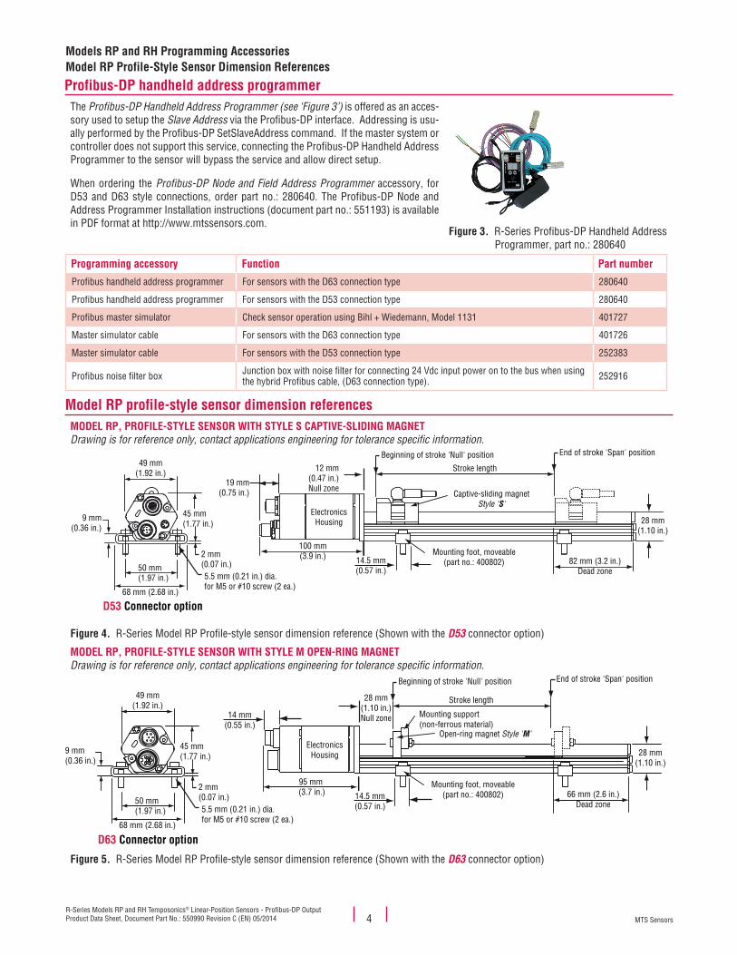
The Profibus-DP Handheld Address Programmer (see ‘Figure 3’) is offered as an acces-sory used to setup the Slave Address via the Profibus-DP interface. Addressing is usu-ally performed by the Profibus-DP SetSlaveAddress command. If the master system or controller does not support this service, connecting the Profibus-DP Handheld Address Programmer to the sensor will bypass the service and allow direct setup.
When ordering the Profibus-DP Node and Field Address Programmer accessory, for D53 and D63 style connections, order part no.: 280640. The Profibus-DP Node and Address Programmer Installation instructions (document part no.: 551193) is available in PDF format at http://www.mtssensors.com.
Figure 3. R-Series Profibus-DP Handheld Address Programmer, part no.: 280640
Model RP profile-style sensor dimension referencesMODEL RP, PROFILE-STYLE SENSOR WITH STYLE S CAPTIVE-SLIDING MAGNET Drawing is for reference only, contact applications engineering for tolerance specific information.
ElectronicsHousing
Beginning of stroke 'Null' position End of stroke 'Span' position
Captive-sliding magnetStyle 'S'
Mounting foot, moveable(part no.: 400802)
D53 Connector option
28 mm(1.10 in.)
82 mm (3.2 in.)Dead zone
12 mm(0.47 in.)Null zone
Stroke length
100 mm(3.9 in.) 14.5 mm
(0.57 in.)
19 mm(0.75 in.)
5.5 mm (0.21 in.) dia.for M5 or #10 screw (2 ea.)
45 mm(1.77 in.)
2 mm(0.07 in.)
9 mm(0.36 in.)
49 mm(1.92 in.)
50 mm(1.97 in.)
68 mm (2.68 in.)
Figure 4. R-Series Model RP Profile-style sensor dimension reference (Shown with the D53 connector option)
MODEL RP, PROFILE-STYLE SENSOR WITH STYLE M OPEN-RING MAGNET Drawing is for reference only, contact applications engineering for tolerance specific information.
ElectronicsHousing
Open-ring magnet Style 'M'
Mounting support(non-ferrous material)
D63 Connector option
Mounting foot, moveable(part no.: 400802)
Beginning of stroke 'Null' position End of stroke 'Span' position
28 mm(1.10 in.)
66 mm (2.6 in.)Dead zone
28 mm(1.10 in.)Null zone
Stroke length
5.5 mm (0.21 in.) dia.for M5 or #10 screw (2 ea.)
45 mm(1.77 in.)
2 mm(0.07 in.)
9 mm(0.36 in.)
49 mm(1.92 in.)
50 mm(1.97 in.)
68 mm (2.68 in.)
14.5 mm(0.57 in.)
95 mm (3.7 in.)
14 mm(0.55 in.)
Figure 5. R-Series Model RP Profile-style sensor dimension reference (Shown with the D63 connector option)
Programming accessory Function Part number
Profibus handheld address programmer For sensors with the D63 connection type 280640
Profibus handheld address programmer For sensors with the D53 connection type 280640
Profibus master simulator Check sensor operation using Bihl + Wiedemann, Model 1131 401727
Master simulator cable For sensors with the D63 connection type 401726
Master simulator cable For sensors with the D53 connection type 252383
Profibus noise filter box Junction box with noise filter for connecting 24 Vdc input power on to the bus when using the hybrid Profibus cable, (D63 connection type). 252916
Profibus-DP handheld address programmer
MTS SensorsR-Series Models RP and RH Temposonics® Linear-Position Sensors - Profibus-DP Output
Product Data Sheet, Document Part No.: 550990 Revision C (EN) 05/20145
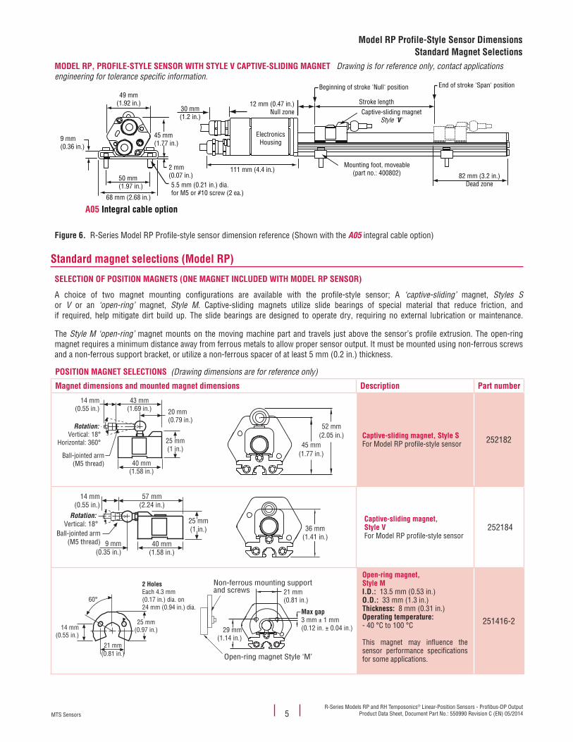
Model RP Profile-Style Sensor DimensionsStandard Magnet Selections
MODEL RP, PROFILE-STYLE SENSOR WITH STYLE V CAPTIVE-SLIDING MAGNET Drawing is for reference only, contact applications engineering for tolerance specific information.
ElectronicsHousing
Captive-sliding magnetStyle 'V'
A05 Integral cable option
Mounting foot, moveable(part no.: 400802)
5.5 mm (0.21 in.) dia.for M5 or #10 screw (2 ea.)
45 mm(1.77 in.)
2 mm(0.07 in.)
9 mm(0.36 in.)
49 mm(1.92 in.)
50 mm(1.97 in.)
68 mm (2.68 in.)
Beginning of stroke 'Null' position End of stroke 'Span' position
82 mm (3.2 in.)Dead zone
12 mm (0.47 in.)Null zone
Stroke length30 mm(1.2 in.)
111 mm (4.4 in.)
Figure 6. R-Series Model RP Profile-style sensor dimension reference (Shown with the A05 integral cable option)
Standard magnet selections (Model RP)
SELECTION OF POSITION MAGNETS (ONE MAGNET INCLUDED WITH MODEL RP SENSOR)
A choice of two magnet mounting configurations are available with the profile-style sensor; A ‘captive-sliding’ magnet, Styles S or V or an ‘open-ring’ magnet, Style M. Captive-sliding magnets utilize slide bearings of special material that reduce friction, and if required, help mitigate dirt build up. The slide bearings are designed to operate dry, requiring no external lubrication or maintenance.
The Style M ‘open-ring’ magnet mounts on the moving machine part and travels just above the sensor’s profile extrusion. The open-ring magnet requires a minimum distance away from ferrous metals to allow proper sensor output. It must be mounted using non-ferrous screws and a non-ferrous support bracket, or utilize a non-ferrous spacer of at least 5 mm (0.2 in.) thickness.
POSITION MAGNET SELECTIONS (Drawing dimensions are for reference only)
Magnet dimensions and mounted magnet dimensions Description Part number
40 mm(1.58 in.)
25 mm(1 in.)
20 mm(0.79 in.)
43 mm(1.69 in.)
14 mm(0.55 in.)
Rotation: Vertical: 18°
Horizontal: 360°
Ball-jointed arm(M5 thread)
Captive-sliding magnet, Style SFor Model RP profile-style sensor 252182
40 mm(1.58 in.)
25 mm(1 in.)
9 mm(0.35 in.)
57 mm(2.24 in.)
14 mm(0.55 in.)
Rotation: Vertical: 18°
Ball-jointed arm(M5 thread)
Captive-sliding magnet,Style VFor Model RP profile-style sensor
252184
21 mm(0.81 in.)
25 mm(0.97 in.)14 mm
(0.55 in.)
2 HolesEach 4.3 mm(0.17 in.) dia. on24 mm (0.94 in.) dia.
60°
Open-ring magnet,Style MI.D.: 13.5 mm (0.53 in.)O.D.: 33 mm (1.3 in.)Thickness: 8 mm (0.31 in.)Operating temperature: - 40 °C to 100 °C
This magnet may influence the sensor performance specifications for some applications.
251416-2
45 mm(1.77 in.)
52 mm(2.05 in.)
36 mm(1.41 in.)
21 mm(0.81 in.)
29 mm(1.14 in.)
Max gap3 mm ± 1 mm(0.12 in. ± 0.04 in.)
Non-ferrous mounting supportand screws
Open-ring magnet Style ‘M’
MTS SensorsR-Series Models RP and RH Temposonics® Linear-Position Sensors - Profibus-DP OutputProduct Data Sheet, Document Part No.: 550990 Revision C (EN) 05/2014 6
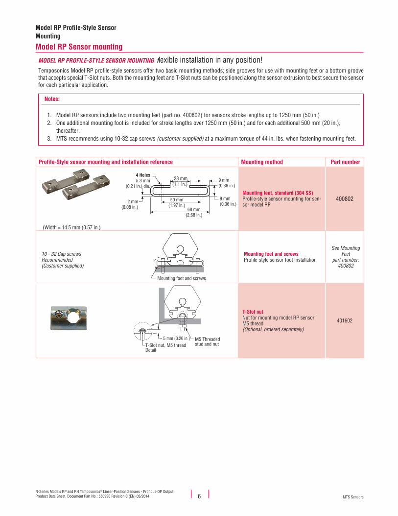
Model RP Profile-Style Sensor Mounting
Model RP Sensor mounting
MODEL RP PROFILE-STYLE SENSOR MOUNTING flexible installation in any position!Temposonics Model RP profile-style sensors offer two basic mounting methods; side grooves for use with mounting feet or a bottom groove that accepts special T-Slot nuts. Both the mounting feet and T-Slot nuts can be positioned along the sensor extrusion to best secure the sensor for each particular application.
Notes:
1. Model RP sensors include two mounting feet (part no. 400802) for sensors stroke lengths up to 1250 mm (50 in.)2. One additional mounting foot is included for stroke lengths over 1250 mm (50 in.) and for each additional 500 mm (20 in.),
thereafter.3. MTS recommends using 10-32 cap screws (customer supplied) at a maximum torque of 44 in. lbs. when fastening mounting feet.
Profile-Style sensor mounting and installation reference Mounting method Part number
(Width = 14.5 mm (0.57 in.)
Mounting feet, standard (304 SS)Profile-style sensor mounting for sen-sor model RP
400802
10 - 32 Cap screwsRecommended(Customer supplied)
Mounting feet and screwsProfile-style sensor foot installation
See Mounting Feet
part number:400802
T-Slot nut Nut for mounting model RP sensorM5 thread (Optional, ordered separately)
401602
4 Holes5.3 mm
(0.21 in.) dia.
28 mm(1.1 in.)
9 mm(0.36 in.)
50 mm(1.97 in.)
2 mm(0.08 in.) 68 mm
(2.68 in.)
9 mm(0.36 in.)
Mounting foot and screws
5 mm (0.20 in.)T-Slot nut, M5 threadDetail
M5 Threadedstud and nut
MTS SensorsR-Series Models RP and RH Temposonics® Linear-Position Sensors - Profibus-DP Output
Product Data Sheet, Document Part No.: 550990 Revision C (EN) 05/20147
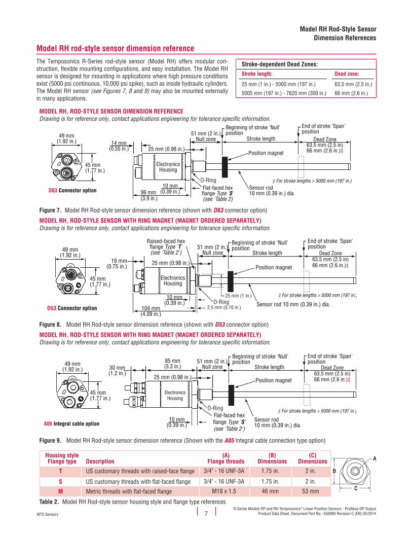
Model RH Rod-Style SensorDimension References
Model RH rod-style sensor dimension referenceThe Temposonics R-Series rod-style sensor (Model RH) offers modular con-struction, flexible mounting configurations, and easy installation. The Model RH sensor is designed for mounting in applications where high pressure conditions exist (5000 psi continuous, 10,000 psi spike), such as inside hydraulic cylinders. The Model RH sensor (see Figures 7, 8 and 9) may also be mounted externally in many applications.
Stroke-dependent Dead Zones:Stroke length:
25 mm (1 in.) - 5000 mm (197 in.)
5005 mm (197 in.) - 7620 mm (300 in.)
Dead zone:
63.5 mm (2.5 in.)
66 mm (2.6 in.)
MODEL RH, ROD-STYLE SENSOR DIMENSION REFERENCE Drawing is for reference only, contact applications engineering for tolerance specific information.
Figure 7. Model RH Rod-style sensor dimension reference (shown with D63 connector option
ElectronicsHousing
D63 Connector option
Beginning of stroke 'Null'position
End of stroke 'Span'position
Dead Zone63.5 mm (2.5 in)66 mm (2.6 in.)‡
Stroke length
45 mm(1.77 in.)
49 mm(1.92 in.)
99 mm (3.9 in.)
Position magnet
Flat-faced hexflange Type 'S'(see 'Table 2)
Sensor rod10 mm (0.39 in.) dia.
10 mm(0.39 in.)
14 mm(0.55 in.)
51 mm (2 in.)Null zone
25 mm (0.98 in.)
O-Ring ‡ For stroke lengths > 5000 mm (197 in.)
)
MODEL RH, ROD-STYLE SENSOR WITH RING MAGNET (MAGNET ORDERED SEPARATELY) Drawing is for reference only, contact applications engineering for tolerance specific information.
Figure 8.
ElectronicsHousing
Beginning of stroke 'Null'position
End of stroke 'Span'position
D53 Connector option
51 mm (2 in.)Null zone Stroke length
104 mm(4.09 in.)
19 mm(0.75 in.)
45 mm(1.77 in.)
49 mm(1.92 in.)
Raised-faced hexflange Type 'T'(see 'Table 2')
Sensor rod 10 mm (0.39 in.) dia.10 mm
(0.39 in.)
25 mm (0.98 in.)Position magnet
O-Ring
Dead Zone63.5 mm (2.5 in)66 mm (2.6 in.)‡
‡ For stroke lengths > 5000 mm (197 in.)25 mm (1 in.)
2.5 mm (0.10 in.)
Model RH Rod-style sensor dimension reference (shown with D53 connector option)
MODEL RH, ROD-STYLE SENSOR WITH RING MAGNET (MAGNET ORDERED SEPARATELY) Drawing is for reference only, contact applications engineering for tolerance specific information.
Figure 9.
ElectronicsHousing
A05 Integral cable option
45 mm(1.77 in.)
49 mm(1.92 in.)
85 mm(3.3 in.)
Beginning of stroke 'Null'position
End of stroke 'Span'position
Stroke length
Flat-faced hexflange Type 'S'(see 'Table 2')
10 mm(0.39 in.)
51 mm (2 in.)Null zone
25 mm (0.98 in.) Position magnet
30 mm(1.2 in.)
O-Ring
Dead Zone63.5 mm (2.5 in)66 mm (2.6 in.)‡
Sensor rod10 mm (0.39 in.) dia.
‡ For stroke lengths > 5000 mm (197 in.)
Model RH Rod-style sensor dimension reference (Shown with the A05 Integral cable connection type option)
Housing styleFlange type Description
(A)Flange threads
(B)Dimensions
(C)Dimensions
B
C
A
T US customary threads with raised-face flange 3/4" - 16 UNF-3A 1.75 in. 2 in.
S US customary threads with flat-faced flange 3/4" - 16 UNF-3A 1.75 in. 2 in.
M Metric threads with flat-faced flange M18 x 1.5 46 mm 53 mm
Table 2. Model RH Rod-style sensor housing style and flange type references
MTS SensorsR-Series Models RP and RH Temposonics® Linear-Position Sensors - Profibus-DP OutputProduct Data Sheet, Document Part No.: 550990 Revision C (EN) 05/2014 8
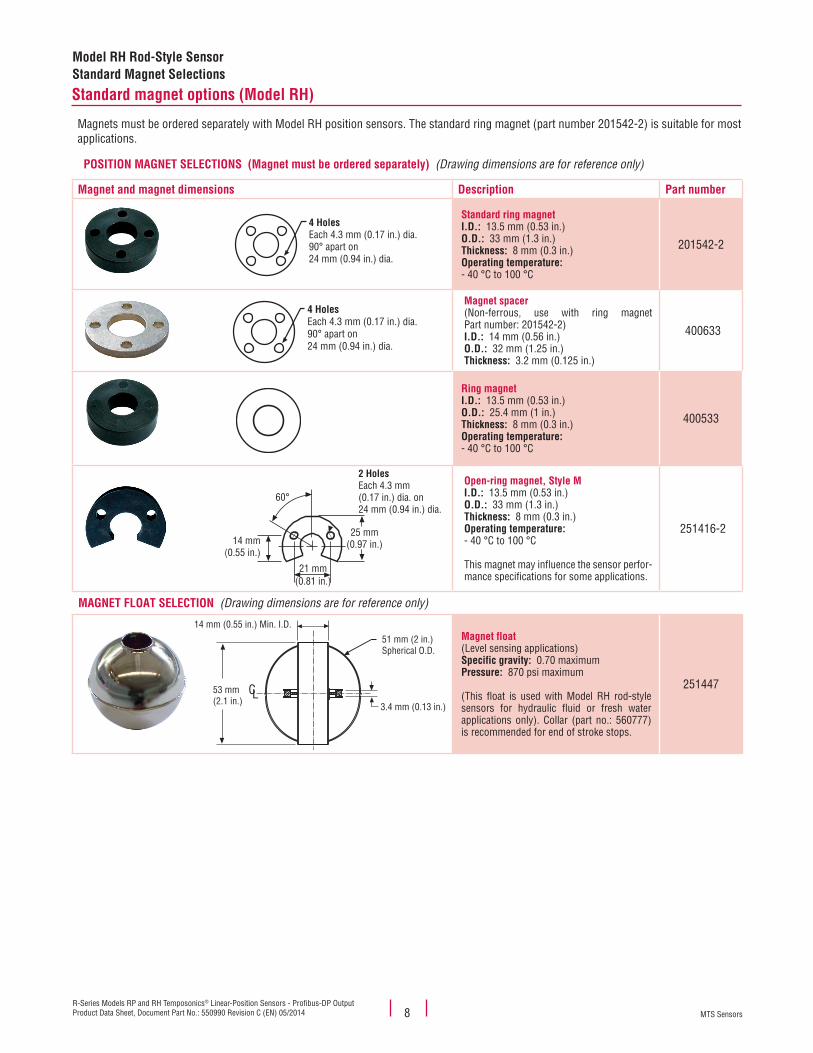
Model RH Rod-Style SensorStandard Magnet Selections
Standard magnet options (Model RH)
Magnets must be ordered separately with Model RH position sensors. The standard ring magnet (part number 201542-2) is suitable for most applications.
POSITION MAGNET SELECTIONS (Magnet must be ordered separately) (Drawing dimensions are for reference only)
Magnet and magnet dimensions Description Part number
Standard ring magnetI.D.: 13.5 mm (0.53 in.)O.D.: 33 mm (1.3 in.)Thickness: 8 mm (0.3 in.)Operating temperature: - 40 °C to 100 °C
201542-2
Magnet spacer(Non-ferrous, use with ring magnet Part number: 201542-2)I.D.: 14 mm (0.56 in.)O.D.: 32 mm (1.25 in.)Thickness: 3.2 mm (0.125 in.)
400633
Ring magnetI.D.: 13.5 mm (0.53 in.)O.D.: 25.4 mm (1 in.)Thickness: 8 mm (0.3 in.)Operating temperature: - 40 °C to 100 °C
400533
Open-ring magnet, Style MI.D.: 13.5 mm (0.53 in.)O.D.: 33 mm (1.3 in.)Thickness: 8 mm (0.3 in.)Operating temperature: - 40 °C to 100 °C
This magnet may influence the sensor perfor-mance specifications for some applications.
251416-2
MAGNET FLOAT SELECTION (Drawing dimensions are for reference only)
Magnet float(Level sensing applications)Specific gravity: 0.70 maximumPressure: 870 psi maximum
(This float is used with Model RH rod-style sensors for hydraulic fluid or fresh water applications only). Collar (part no.: 560777) is recommended for end of stroke stops.
251447
4 HolesEach 4.3 mm (0.17 in.) dia.90° apart on 24 mm (0.94 in.) dia.
4 HolesEach 4.3 mm (0.17 in.) dia.90° apart on 24 mm (0.94 in.) dia.
21 mm(0.81 in.)
25 mm(0.97 in.)14 mm
(0.55 in.)
2 HolesEach 4.3 mm(0.17 in.) dia. on24 mm (0.94 in.) dia.
60°
14 mm (0.55 in.) Min. I.D.
51 mm (2 in.)Spherical O.D.
3.4 mm (0.13 in.)
CL53 mm(2.1 in.)
MTS SensorsR-Series Models RP and RH Temposonics® Linear-Position Sensors - Profibus-DP Output
Product Data Sheet, Document Part No.: 550990 Revision C (EN) 05/20149
Model RH Rod-Style SensorsMounting, Connections and Wiring
Connections and wiring
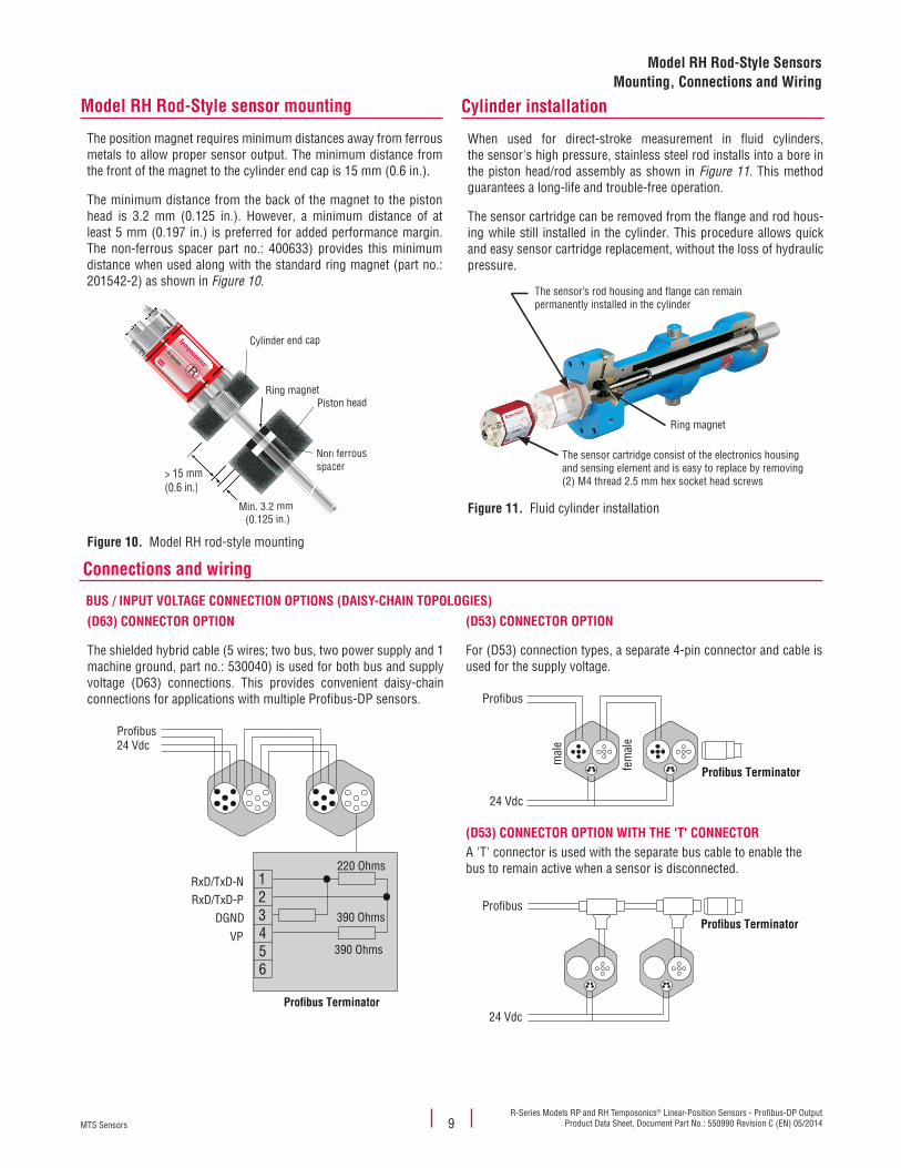
BUS / INPUT VOLTAGE CONNECTION OPTIONS (DAISY-CHAIN TOPOLOGIES)(D63) CONNECTOR OPTION
The shielded hybrid cable (5 wires; two bus, two power supply and 1 machine ground, part no.: 530040) is used for both bus and supply voltage (D63) connections. This provides convenient daisy-chain connections for applications with multiple Profibus-DP sensors.
Profibus24 Vdc
RxD/TxD-NRxD/TxD-P
DGND
VP
220 Ohms
390 Ohms
390 Ohms
1
6
2345
Pro�bus Terminator
(D53) CONNECTOR OPTION
For (D53) connection types, a separate 4-pin connector and cable is used for the supply voltage.
Pro�bus Terminator
Profibus
24 Vdc
mal
e
fem
ale
(D53) CONNECTOR OPTION WITH THE 'T' CONNECTORA 'T' connector is used with the separate bus cable to enable the bus to remain active when a sensor is disconnected.
24 Vdc
ProfibusPro�bus Terminator
Model RH Rod-Style sensor mounting
The position magnet requires minimum distances away from ferrous metals to allow proper sensor output. The minimum distance from the front of the magnet to the cylinder end cap is 15 mm (0.6 in.).
The minimum distance from the back of the magnet to the piston head is 3.2 mm (0.125 in.). However, a minimum distance of at least 5 mm (0.197 in.) is preferred for added performance margin. The non-ferrous spacer part no.: 400633) provides this minimum distance when used along with the standard ring magnet (part no.: 201542-2) as shown in Figure 10.
Figure 10.
Non ferrous spacer
> 15 mm (0.6 in.)
Min. 3.2 mm (0.125 in.)
Ring magnet
n fercer
mmmm.)
(0.125 in.)
magnetRing m
Nonspa
Min. 3.2 mm
magnetRing m
Cylinder end cap
Piston head
Temposonics ®
R-Series R®
Model RH rod-style mounting
Cylinder installation
When used for direct-stroke measurement in fluid cylinders, the sensor's high pressure, stainless steel rod installs into a bore in the piston head/rod assembly as shown in Figure 11. This method guarantees a long-life and trouble-free operation.
The sensor cartridge can be removed from the flange and rod hous-ing while still installed in the cylinder. This procedure allows quick and easy sensor cartridge replacement, without the loss of hydraulic pressure.
The sensor’s rod housing and flange can remainpermanently installed in the cylinder
Ring magnet
The sensor cartridge consist of the electronics housingand sensing element and is easy to replace by removing(2) M4 thread 2.5 mm hex socket head screws
Figure 11. Fluid cylinder installation
MTS SensorsR-Series Models RP and RH Temposonics® Linear-Position Sensors - Profibus-DP OutputProduct Data Sheet, Document Part No.: 550990 Revision C (EN) 05/2014 10
Model RP and RH SensorsConnections and Wiring
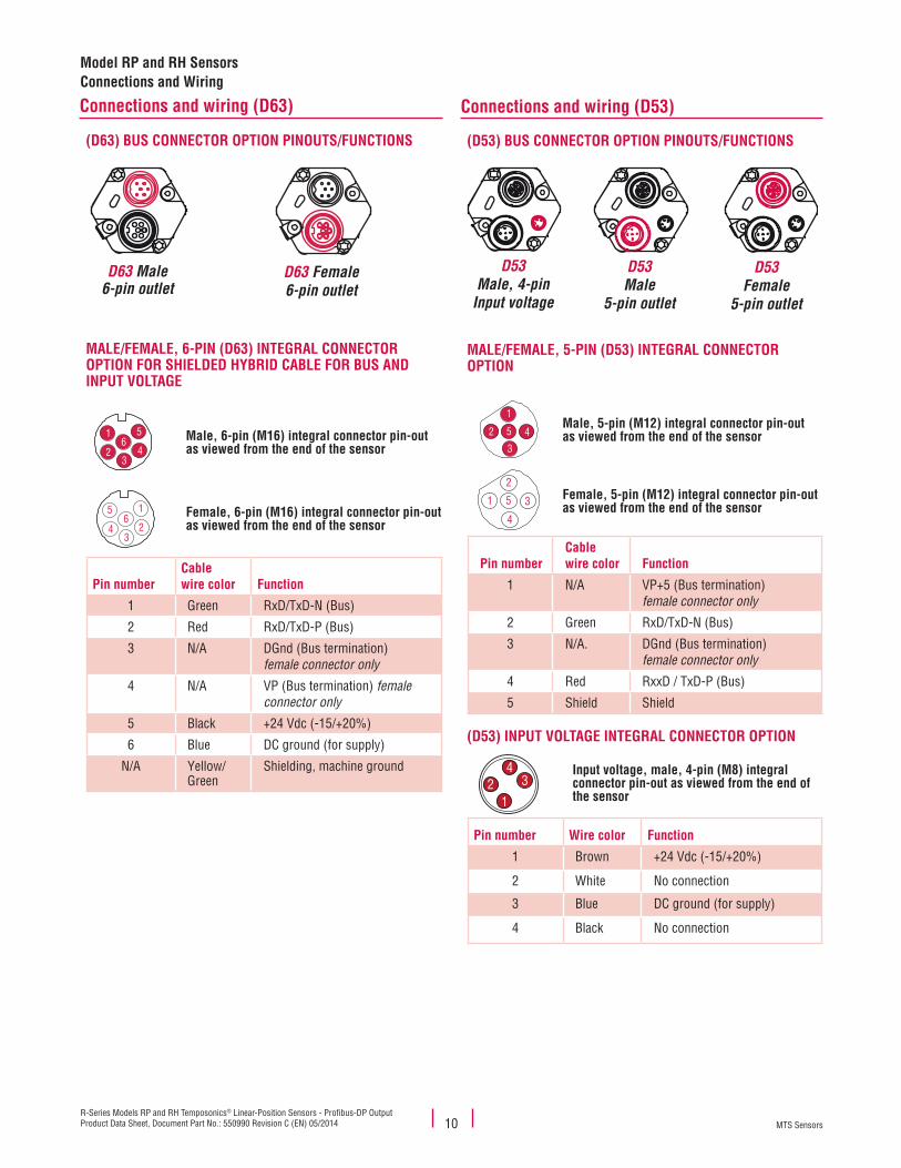
Connections and wiring (D63)
(D63) BUS CONNECTOR OPTION PINOUTS/FUNCTIONS
D63 Male6-pin outlet
D63 Female6-pin outlet
MALE/FEMALE, 6-PIN (D63) INTEGRAL CONNECTOR OPTION FOR SHIELDED HYBRID CABLE FOR BUS AND INPUT VOLTAGE
1
23
64
5 1
23
64
5 Male, 6-pin (M16) integral connector pin-out as viewed from the end of the sensor
1
23
64
5 1
23
64
5 Female, 6-pin (M16) integral connector pin-out as viewed from the end of the sensor
Pin numberCablewire color Function
1 Green RxD/TxD-N (Bus)
2 Red RxD/TxD-P (Bus)
3 N/A DGnd (Bus termination) female connector only
4 N/A VP (Bus termination) female connector only
5 Black +24 Vdc (-15/+20%)
6 Blue DC ground (for supply)
N/A Yellow/Green
Shielding, machine ground
Connections and wiring (D53)
(D53) BUS CONNECTOR OPTION PINOUTS/FUNCTIONS
D53Male
5-pin outlet
D53Female
5-pin outlet
D53Male, 4-pin
Input voltage
MALE/FEMALE, 5-PIN (D53) INTEGRAL CONNECTOR OPTION
1
2
3
5 4 5 3
4
1
2Male, 5-pin (M12) integral connector pin-out as viewed from the end of the sensor
1
2
3
5 4 5 3
4
1
2Female, 5-pin (M12) integral connector pin-out as viewed from the end of the sensor
Pin numberCablewire color Function
1 N/A VP+5 (Bus termination)female connector only
2 Green RxD/TxD-N (Bus)
3 N/A. DGnd (Bus termination) female connector only
4 Red RxxD / TxD-P (Bus)
5 Shield Shield
(D53) INPUT VOLTAGE INTEGRAL CONNECTOR OPTION
34
21
Input voltage, male, 4-pin (M8) integral connector pin-out as viewed from the end of the sensor
Pin number Wire color Function
1 Brown +24 Vdc (-15/+20%)
2 White No connection
3 Blue DC ground (for supply)
4 Black No connection
MTS SensorsR-Series Models RP and RH Temposonics® Linear-Position Sensors - Profibus-DP Output
Product Data Sheet, Document Part No.: 550990 Revision C (EN) 05/201411
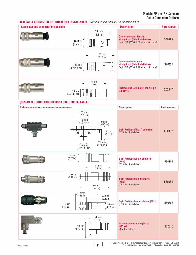
(D63) CABLE CONNECTOR OPTIONS (FIELD INSTALLABLE) (Drawing dimensions are for reference only)
Connector and connector dimensions Description Part number
Cable connector, female,straight exit (field installation)6-pin DIN (M16) PG9 size strain relief
370423
Cable connector, male, straight exit (field installation)6-pin DIN (M16) PG9 size strain relief
370427
Profibus Bus terminator, male 6-pin DIN (M16) 252347
(D53) CABLE CONNECTOR OPTIONS (FIELD INSTALLABLE)
Cable connectors and dimension references Description Part number
5-pin Profibus (M12) T connector(D53 field installable) 560887
5-pin Profibus female connector (M12)(D53 field installable)
560885
5-pin Profibus male connector (M12)(D53 field installable)
560884
5-pin Profibus bus terminator (M12)(D53 field installable) 560888
5-pin male connector (M12) 90° exit(Field installable)
370515
54 mm(2.1 in.)
18 mm(0.7 in.)
58 mm(2.28 in.)
18 mm(0.7 in.) dia.
48 mm(1.9 in.)
18 mm(0.7 in.) dia.
70 mm(2.75 in.)
40 mm(1.58 in.)
41 mm(1.6 in.)
9 mm(0.36 in.)
29 mm(1.15 in.)19 mm
(0.74 in.) dia.
20 mm(0.77 in.)
57 mm(2.24 in.)
20 mm(0.77 in.)
62 mm(2.44 in.)
16 mm(0.64 in.)
43 mm(1.69 in.) 22 mm
(0.87 in)
14 mm(0.55 in.)
54 mm(1.12 in.)
40 mm(1.57 in.)
Models RP and RH SensorsCable Connector Options
MTS SensorsR-Series Models RP and RH Temposonics® Linear-Position Sensors - Profibus-DP OutputProduct Data Sheet, Document Part No.: 550990 Revision C (EN) 05/2014
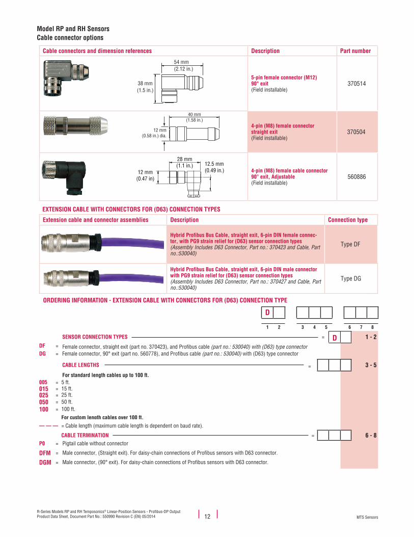
Cable connectors and dimension references Description Part number
5-pin female connector (M12) 90° exit(Field installable)
370514
4-pin (M8) female connector straight exit(Field installable)
370504
4-pin (M8) female cable connector 90° exit, Adjustable(Field installable)
560886
EXTENSION CABLE WITH CONNECTORS FOR (D63) CONNECTION TYPES
Extension cable and connector assemblies Description Connection type
Hybrid Profibus Bus Cable, straight exit, 6-pin DIN female connec-tor, with PG9 strain relief for (D63) sensor connection types(Assembly Includes D63 Connector, Part no.: 370423 and Cable, Part no.:530040)
Type DF
Hybrid Profibus Bus Cable, straight exit, 6-pin DIN male connector with PG9 strain relief for (D63) sensor connection types(Assembly Includes D63 Connector, Part no.: 370427 and Cable, Part no.:530040)
Type DG
ORDERING INFORMATION - EXTENSION CABLE WITH CONNECTORS FOR (D63) CONNECTION TYPE
D
1 2 3 4 5 6 7 8
SENSOR CONNECTION TYPES = D 1 - 2DF = Female connector, straight exit (part no. 370423), and Profibus cable (part no.: 530040) with (D63) type connectorDG = Female connector, 90° exit (part no. 560778), and Profibus cable (part no.: 530040) with (D63) type connector
CABLE LENGTHS = 3 - 5
For standard length cables up to 100 ft.005 = 5 ft. 015 = 15 ft.025 = 25 ft.050 = 50 ft.100 = 100 ft.
For custom length cables over 100 ft.— — — = Cable length (maximum cable length is dependent on baud rate).
CABLE TERMINATION = 6 - 8P0 = Pigtail cable without connector
DFM = Male connector, (Straight exit). For daisy-chain connections of Profibus sensors with D63 connector.
DGM = Male connector, (90° exit). For daisy-chain connections of Profibus sensors with D63 connector.
54 mm(2.12 in.)
38 mm(1.5 in.)
40 mm(1.58 in.)
12 mm(0.58 in.) dia.
12 mm(0.47 in)
28 mm(1.1 in.) 12.5 mm
(0.49 in.)
12
Model RP and RH SensorsCable connector options
MTS SensorsR-Series Models RP and RH Temposonics® Linear-Position Sensors - Profibus-DP Output
Product Data Sheet, Document Part No.: 550990 Revision C (EN) 05/2014
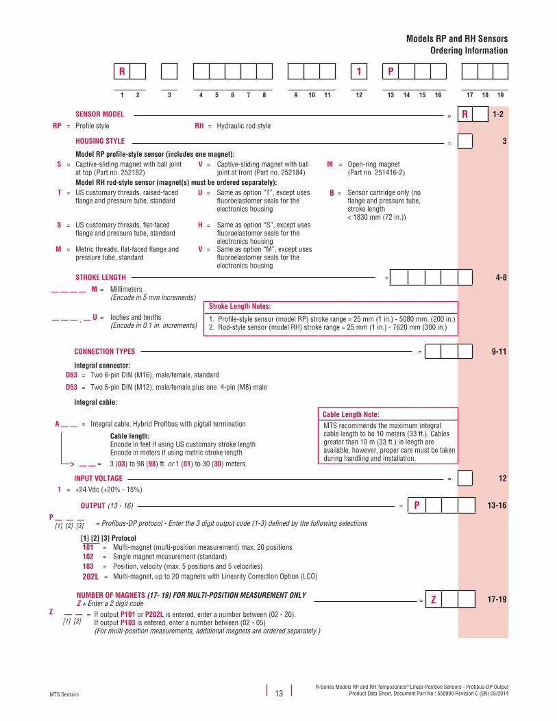
R 1 P
1 2 3 4 5 6 7 8 9 10 11 12 13 14 15 16 17 18 19
SENSOR MODEL = R 1-2RP = Profile style RH = Hydraulic rod style
HOUSING STYLE = 3
Model RP profile-style sensor (includes one magnet):S = Captive-sliding magnet with ball joint
at top (Part no. 252182)V = Captive-sliding magnet with ball
joint at front (Part no. 252184)M = Open-ring magnet
(Part no. 251416-2)Model RH rod-style sensor (magnet(s) must be ordered separately):
T = US customary threads, raised-faced flange and pressure tube, standard
U = Same as option “T”, except uses fluoroelastomer seals for the electronics housing
B = Sensor cartridge only (no flange and pressure tube, stroke length < 1830 mm (72 in.))
S = US customary threads, flat-faced flange and pressure tube, standard
H = Same as option “S”, except uses fluoroelastomer seals for the electronics housing
M = Metric threads, flat-faced flange and pressure tube, standard
V = Same as option “M”, except uses fluoroelastomer seals for the electronics housing
STROKE LENGTH = 4-8
— — — — M = Millimeters(Encode in 5 mm increments)
Stroke Length Notes:
— — — . — U = Inches and tenths(Encode in 0.1 in. increments)
1. Profile-style sensor (model RP) stroke range = 25 mm (1 in.) - 5080 mm. (200 in.)2. Rod-style sensor (model RH) stroke range = 25 mm (1 in.) - 7620 mm (300 in.)
CONNECTION TYPES = 9-11
Integral connector:D63 = Two 6-pin DIN (M16), male/female, standard
D53 = Two 5-pin DIN (M12), male/female plus one 4-pin (M8) male
Integral cable:
Cable Length Note:A — — = Integral cable, Hybrid Profibus with pigtail termination MTS recommends the maximum integral
cable length to be 10 meters (33 ft.). Cables greater than 10 m (33 ft.) in length are available, however, proper care must be taken during handling and installation.
Cable length: Encode in feet if using US customary stroke lengthEncode in meters if using metric stroke length
> — — = 3 (03) to 98 (98) ft. or 1 (01) to 30 (30) meters.
INPUT VOLTAGE = 121 = +24 Vdc (+20% - 15%)
13
Models RP and RH SensorsOrdering Information
OUTPUT (13 - 16) = P 13-16P — — — [1] [2] [3] = Profibus-DP protocol - Enter the 3 digit output code (1-3) defined by the following selections
[1] [2] [3] Protocol101 = Multi-magnet (multi-position measurement) max. 20 positions102 = Single magnet measurement (standard)103 = Position, velocity (max. 5 positions and 5 velocities)202L = Multi-magnet, up to 20 magnets with Linearity Correction Option (LCO)
NUMBER OF MAGNETS (17- 19) FOR MULTI-POSITION MEASUREMENT ONLYZ + Enter a 2 digit code = Z 17-19
Z — — [1] [2]
= If output P101 or P202L is entered, enter a number between (02 - 20). If output P103 is entered, enter a number between (02 - 05) (For multi-position measurements, additional magnets are ordered separately.)
Document Part number: 550990 Revision C (EN) 05/2014
MTS, Temposonics and Level Plus are registered trademarks of MTS Systems Corporation. All other trademarks are the property of their respective owners. Printed in USA. Copyright © 2014 MTS Systems Corporation. All Rights Reserved in all media.
All specifications are subject to change. Contact MTS for specifications and engineering drawings that are critical to your application. Drawings contained in this document are for reference only. Go to http://www.mtssensors.com for the latest product information.
LOCA
TION
S
LEGA
L NO
TICE
SUSAMTS Systems CorporationSensors Division3001 Sheldon DriveCary, N.C. 27513, USATel. +1 919 677-0100Fax +1 919 [email protected]
GERMANYMTS Sensor TechnologieGmbH & Co. KGAuf dem Schüffel 958513 Lüdenscheid, GermanyTel. + 49 2351 9587-0Fax + 49 2351 [email protected]
JAPANMTS Sensors Technology Corp.737 Aihara-machi, Machida-shi, Tokyo 194-0211, JapanTel. + 81 42 775-3838Fax + 81 42 775- [email protected]
FRANCEMTS Systems SASZone EUROPARC Bâtiment EXA 1616/18, rue Eugène Dupuis94046 Creteil, FranceTel. + 33 1 58 4390-28Fax + 33 1 58 [email protected]
ITALYMTS Systems Srl.Sensor DivisionVia Diaz,425050 Provaglio d‘Iseo (BS), ItalyTel. + 39 030 988 3819Fax + 39 030 982 [email protected]
CHINAMTS Sensors Room 504, Huajing Commercial Center, No. 188, North Qinzhou Road200233 Shanghai, ChinaTel. +86 21 6485 5800 Fax +86 21 6495 [email protected]