product data sheet: rosemount 848t high density ... · product data sheet 00813-0100-4697, rev rb...
TRANSCRIPT

Product Data Sheet00813-0100-4697, Rev RB
September 2019
Rosemount™ 848T High Density TemperatureMeasurement Family
■ Innovative temperature measurement for high density applications that provide installation andoperational savings.
■ Independently configurable inputs that support RTD, thermocouple, ohm, mV, 0–10 volt, and 4–20 mAsignals.
■ Enclosure options and intrinsically safe design allows for installation close to any process, includinghazardous areas.
■ WirelessHART® capabilities extends the full benefits of Plantweb™ to previously inaccessible locations.
■ Industry first measurement validation diagnostic can identify a variety of process concerns includingsensor degradation, sensor wiring connectivity, high vibration (affecting the measurement), andabnormal process variations.
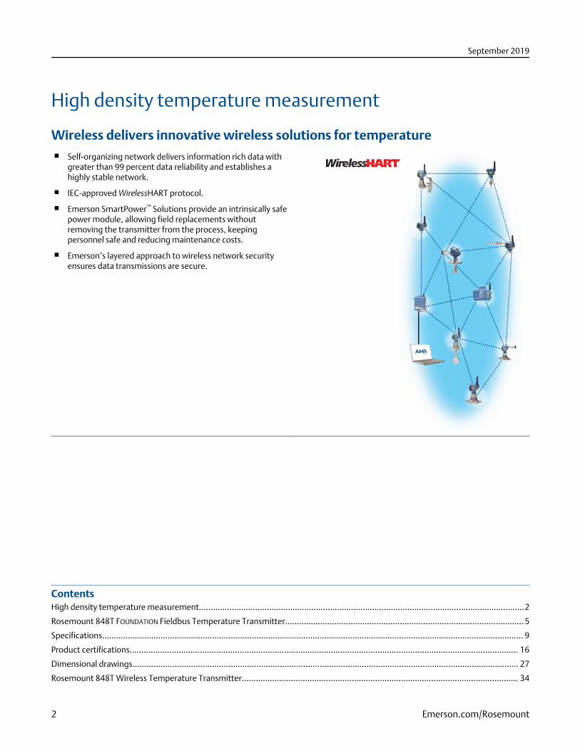
High density temperature measurement
Wireless delivers innovative wireless solutions for temperature■ Self-organizing network delivers information rich data with
greater than 99 percent data reliability and establishes ahighly stable network.
■ IEC-approved WirelessHART protocol.
■ Emerson SmartPower™ Solutions provide an intrinsically safepower module, allowing field replacements withoutremoving the transmitter from the process, keepingpersonnel safe and reducing maintenance costs.
■ Emerson’s layered approach to wireless network securityensures data transmissions are secure.
ContentsHigh density temperature measurement...........................................................................................................................................2
Rosemount 848T FOUNDATION Fieldbus Temperature Transmitter...................................................................................................... 5
Specifications.................................................................................................................................................................................... 9
Product certifications...................................................................................................................................................................... 16
Dimensional drawings..................................................................................................................................................................... 27
Rosemount 848T Wireless Temperature Transmitter...................................................................................................................... 34
September 2019
2 Emerson.com/Rosemount

FOUNDATION™ Fieldbus provides effective measurements with reduced wiring
costs■ Internationally recognized digital network (IEC 61158)
supports the connection of up to 16 devices on a singletwisted wire pair.
■ Allows advanced computations through use of functionblocks.
■ Provides continuous measurement status for eachmeasurement point.
■ Lower costs by reducing wiring, terminations, and requirednumber of I.S. Barriers.
Explore the benefits of Complete Point Solution™ from RosemountTemperature Measurement■ Emerson offers a selection of RTDs and thermocouples that
bring superior durability and Rosemount reliability totemperature sensing.
■ A broad thermowell offering meets the demandingrequirements of a variety of process applications.
Increase performance with High Density transmitters■ Transmit multiple measurements with one set of
electronics.
■ Mount close to process to reduce sensor wire length andincrease measurement reliability.
■ Enhance accuracy with EMI correction, cold junctioncompensation, and device diagnostics.
■ Reduce installation costs by as much as 70 percent.
September 2019
Emerson.com/Rosemount 3

Avoid unnecessary process shutdowns, on-scale failure related issues, andunsafe process conditions with measurement validation diagnostic■ Detect measurement abnormalities and take preventive
action before shutdown is necessary.
■ Determine validity of data points that are outside of alarmlimits.
■ Identify on-scale failures and take action before processefficiency and safety is compromised.
■ Detect abnormally fast process rates of change before alarmstate is reached.
High density temperature measurement
Ideal solution for taking multiple measurements in closeproximity to each other such as:■ Bearing temperature on pumps and motors
■ Distillation columns
■ Furnaces and boilers
■ Reactors, storage tanks, and many more
Simplify installation and reduce wiring costs■ Eliminate marshalling
■ Less wire routing and fewer terminations
■ Faster startups with fewer devices
Access powerful information with new device dashboards■ Leverage Human Centered Design practices to create an
intuitive user interface.
■ Instantly see status and output of each sensor.
■ Direct links to graphical diagnostics and troubleshootinghelp.
■ Drastically lower configuration time.
September 2019
4 Emerson.com/Rosemount

Rosemount 848T FOUNDATION Fieldbus TemperatureTransmitter
The Rosemount 848T offers a low cost solution for high densitymeasurements. The transmitter accepts eight independentlyconfigurable sensor inputs, and can be mounted close to theprocess to improve data quality.FOUNDATION Fieldbusarchitecture allows up to 128 temperature measurements to betransmitted on a single H1 Fieldbus line. Additionally, thetransmitter is bus-powered, further reducing the amount ofrequired wiring to install the device. The robust design hasproven itself in thousands of successful installations.Capabilities include:■ Eight independently configurable inputs, including 2- and 3-
wire RTDs, thermocouples, mV, 2- and 3-wire ohms, and 4–20 mA signals
■ Industry first measurement validation diagnostic
■ Fieldbus functionality with eight AI blocks, two MAI blocks,four ISEL Blocks, and backup LAS capabilities
■ 600 Vdc isolation and integral transient protection
Specification and selection of product materials, options, or components must be made by the purchaser of the equipment. SeeMaterial selection for more information.
Table 1: Rosemount 848T FOUNDATION Fieldbus Ordering Table
The starred offerings (★) represent the most common options and should be selected for best delivery. The non-starred offeringsare subject to additional delivery lead time.
Model Product description
848T High Density Temperature Measurement Family
Transmitter output
F FOUNDATION Fieldbus digital signal (includes AI, MAI, and ISEL function blocks, and Backup Link Active Scheduler) ★
Product certifications(1) Rosemount Junction Box required?
I1 ATEX Intrinsic Safety No ★
I2 INMETRO Intrinsic Safety No ★
I3 NEPSI Intrinsic Safety No ★
I4 TIIS Intrinsically Safety (FISCO) Type 'ia’ No
H4 TIIS Intrinsic Safety (FISCO) Type 'ib’ No
I5(2) FM Intrinsically Safe No ★
I6(2) CSA Intrinsically Safe No ★
I7 IECEx Intrinsic Safety No ★
IA ATEX FISCO Intrinsic Safety No ★
IB INMETRO FISCO Intrinsic Safety No ★
IE FM FISCO Intrinsically Safe No ★
IF(2) CSA FISCO Intrinsically Safe, Division 2 No ★
September 2019
Emerson.com/Rosemount 5
Table 1: Rosemount 848T FOUNDATION Fieldbus Ordering Table (continued)
Model Product description
IG IECEx FISCO (Intrinsic Safety) No ★
IM Technical Regulations Customs Union (EAC) Intrinsic Safety No ★
KG FM, CSA, ATEX, and IECEx Intrinsic Safety No ★
N1 ATEX Type n (enclosure required) Yes ★
N3 China Type n (enclosure required) Yes ★
N5 FM Class I, Division 2, and Dust Ignitionproof (enclosure required) Yes ★
N6 CSA Class I, Division 2 No ★
N7 IECEx Type n (enclosure required) Yes ★
NC ATEX Type n Component (Ex nA nL) No(3) ★
ND ATEX Dust (enclosure required) Yes ★
NJ IECEx Type n Component (Ex nA nL) No(3) ★
NK FM Class I, Division 2 Yes ★
E6 CSA Explosion-proof, Dust Ignitionproof, Division 2 (JX3 enclosure required) Yes(4)
IM Technical Regulations Customs Union (EAC) Intrinsic Safety No ★
IP Korea Intrinsic Safety No ★
NA No approval No ★
Input types
S001 RTD, thermocouple, mV, Ohm inputs ★
S002(5) RTDs, thermocouple, mV, Ohm and 4–20 mA inputs ★
(1) Consult factory for availability.(2) Available only with S001 option.(3) The Rosemount 848T ordered with component approval is not approved as a stand-alone unit. Additional system certification is required.(4) Enclosure Option JX3 must be ordered with Product Certification Code E6. (O-ring for the JX3 enclosure rated to -20 °C).(5) S002 is only available with Product Certification N5, N6, N1, NC, NK, and NA.
Table 2: Options (Include with selected model number)
Plantweb advanced diagnostics
D04 Measurement validation diagnostic ★
Transient protection
T1 Integral transient protector ★
Mounting bracket
B6 Mounting bracket for 2-in. pipe mounting – SST bracket and bolts ★
Enclosure options
JP1 Plastic junction box; no entries ★
JP2 Plastic box, cable glands (9 X M20 nickel-plated brass glands for 7.5–11.9 mm unarmored cable) ★
JP3 Plastic box, conduit entries (five plugged holes, suitable for installing ½-in. NPT fittings) ★
JA1 Aluminum junction box; no entries ★
September 2019
6 Emerson.com/Rosemount

Table 2: Options (Include with selected model number) (continued)
JA2 Aluminum cable glands (9 X M20 nickel-plated brass glands for 7.5–11.9 mm unarmored cable) ★
JA3 Aluminum conduit entries (five plugged holes, suitable for installing ½-in. NPT fittings) ★
JS1 Stainless steel junction box; no entries ★
JS2 Stainless steel box, cable glands (9 X M20 nickel-plated brass glands for 7.5–11.9 mm unarmored cable) ★
JS3 Stainless steel box, conduit entries (five plugged holes, suitable for installing ½-in. NPT fittings) ★
JX3(1) Explosion-proof box, conduit entries (four plugged holes, suitable for installing ½-in. NPT fittings) ★
Software configuration
C1 Custom configuration of date, descriptor, message and wireless parameters (requires CDS with order) ★
Line filter
F5 50 Hz line voltage filter ★
Calibration certificate
Q4 Calibration certificate (3-point calibration) ★
Shipboard certification
SBS American Bureau of Shipping (ABS) Type Approval ★
SBV Bureau Veritas (BV) Type Approval ★
SDN Det Norske Veritas (DNV) Type Approval ★
SLL Lloyd's Register (LR) Type Approval ★
Special temperature test
LT Test to –60 °F (–51.1 °C)
Conduit electrical connector
GE(2) M12, 4-pin, male connector (eurofast®) ★
GM(2) A size mini, 4-pin, male connector (minifast®) ★
Extended product warranty
WR3 3-year limited warranty ★
WR5 5-year limited warranty ★
Typical model number: 848T F I5 S001 T1 B6 JA2
(1) JX3 Explosion-proof enclosure rated to -4 °F (-20 °C).(2) M12, 4-pin, male connector (eurofast)
September 2019
Emerson.com/Rosemount 7

WiringFigure 1: Rosemount 848T Sensor Wiring Diagram
1 1 1 12 2 2 23 3 3 3
2-wire RTD and ohms 3-wire RTD and ohms(1) Thermocouples/ohms andmillivolts
2-wire RTD with compensationloop(2)
(1) Emerson provides 4-wire sensors for all single-element RTDs. Use these RTDs in 3-wire configurations by clipping the fourth lead or leaving itdisconnected and insulated with electrical tape.
(2) The transmitter must be configured for a 3-wire RTD in order to recognize an RTD with a compensation loop.
Standard configurationUnless otherwise specified, the transmitter will be shipped as follows for all eight sensors:
Standard configuration settings
Sensor type(1) Thermocouple Type J
Damping(1) Five seconds
Measurement units(1) °C
Output(1) Linear with temperature
Line voltage filter(1) 60 Hz
Temperature specific blocks Sensor transducer block (1)
FOUNDATION Fieldbus Function Blocks Analog input (8)
Multiple analog input (2)
Input selector (4)
Input transient filter Enabled
(1) For all eight sensors.
September 2019
8 Emerson.com/Rosemount

Specifications
Functional specifications
InputEight independently configurable channels including combinations of 2- and 3-wire RTDs, thermocouples, mV, and 2- and 3-wireohm inputs. 4–20 mA inputs using optional connector(s).
OutputManchester-encoded digital signal that conforms to IEC 61158 and ISA 50.02.
StatusIf self-diagnostics detect a sensor burnout or a transmitter failure, the status of the measurement will be updated accordingly.
Ambient temperature–40 to 185 °F (–40 to 85 °C)
Accuracy(Pt 100 at reference condition: 20 °C) ±0.30 °C (±0.54 °F); for the complete list, see Accuracy table.
Isolation■ 600 Vdc channel to channel isolation(1).
■ 10 Vdc channel to channel isolation for all operating conditions with maximum 150 meters (500 feet) of sensor lead length 18AWG.
Power supplyPowered over FOUNDATION Fieldbus with standard fieldbus power supplies. The transmitter operates between 9.0 and 32.0 Vdc, 22mA maximum. (transmitter power terminals are rated to 42.4 Vdc.)
Transient protectionThe transient protector (option code T1) helps to prevent damage to the transmitter from transients induced on the loop wiring bylightning, welding, heavy electrical equipment, or switch gears. This option is installed at the factory for the Rosemount 848T and isnot intended for field installation.
Update timeApproximately 1.5 seconds to read all eight inputs
Humidity limits0–99 percent non-condensing relative humidity
Turn-on timePerformance within specifications is achieved in less than 30 seconds after power is applied to the transmitter.
(1) Reference conditions are -40 to 140 °F (-40 to 60 °C) with 100 ft. (30 m) of sensor lead length 18 AWG wire.
September 2019
Emerson.com/Rosemount 9

AlarmsThe AI and ISEL function blocks allow the user to configure the alarms to HI-HI, HI, LO, or LO-LO with a variety of priority levels andhysteresis settings.
Electromagnetic compatibility compliance testing■ Meets the criteria under European Union Directive 2004/108/EC.
■ Meets the criteria under IEC 61326: 2006.
Stability■ ±0.1 percent of reading or 0.18 °F (0.1 °C), whichever is greater, for two years for RTDs.
■ ±0.1 percent of reading or 0.18 °F (0.1 °C), whichever is greater, for one year for thermocouples.
Self calibrationThe transmitter’s analog-to-digital circuitry automatically self-calibrates for each temperature update by comparing the dynamicmeasurement to extremely stable and accurate internal reference elements.
Vibration effectTested to the following with no effect on performance per IEC 60770-1, 1999.
Frequency acceleration
10-60 Hz 0.21 mm peak displacement
60-2000 Hz 3 g
Backup Link Active Scheduler (LAS)The transmitter is classified as a device link master, which means it can function as a LAS if the current link master device fails or isremoved from the segment.
The host or other configuration tool is used to download the schedule for the application to the link master device. In the absenceof a primary link master, the transmitter will claim the LAS and provide permanent control for the H1 segment.
Software upgrade in the fieldSoftware for the Rosemount 848T with FOUNDATION Fieldbus is easy to upgrade in the field using the FOUNDATION Fieldbus CommonDevice Software Download procedure.
FOUNDATION Fieldbus parameters
Schedule Entries 20
Links 30
Virtual Communications Relationships (VCR) 20
September 2019
10 Emerson.com/Rosemount

Physical specifications
Conformance to specifications (±3σ [Sigma])Technology leadership, advanced manufacturing techniques, and statistical process control ensure specification conformance to atleast ±3σ.
MountingThe Rosemount 848T can be mounted directly onto a DIN rail or it can be ordered with an optional junction box. When using theoptional junction box, the transmitter can be mounted onto a panel or a 2-in. pipe stand (with option code B6).
Entries for optional junction box
No entry Used for custom fittings.
Cable gland 9 x M20 nickel-plated brass glands for 7.5–11.9 mm unarmored cable
Conduit Five plugged 0.86-in. diameter holes suitable for installing ½-in. NPT fittings.
Materials of construction for optional junction box
Junction box type Paint
Aluminum Epoxy resin
Plastic N/A
Stainless steel N/A
Aluminum explosion-proof N/A
Weight
Assembly Weight
oz lb kg
Rosemount 848T only 7.5 .47 .208
Aluminum(1) 78.2 4.89 2.22
Plastic(1) 58.1 3.68 1.65
Stainless Steel(1) 77.0 4.81 2.18
Aluminum Explosion-proof 557 34.8 15.5
(1) Add 35.2 oz (2.2 lb, 0.998 kg) for nickel-plated brass glands.
Environmental ratingsType 4X and IP66 with optional junction box. JX3 Explosion-proof enclosure rated to –4 °F (–20 °C).
Function blocks
Analog Input (AI)■ Processes the measurement and makes it available on the fieldbus segment.
September 2019
Emerson.com/Rosemount 11

■ Allows filtering, alarming, and engineering unit changes.
Input Selector (ISEL)■ Used to select between inputs and generate an output using specific selection strategies such as minimum, maximum,
midpoint, or average temperature.
■ Since the temperature value always contains the measurement status, this block allows the selection to be restricted to the first“good” measurement.
Multiple Analog Input Block (MAI)■ The MAI block allows the eight AI blocks to be multiplexed together so they serve as one function block on the H1 segment,
resulting in greater network efficiency.
AccuracyTable 3: Input Options/Accuracy
Sensor option Sensor reference Input ranges Accuracy over range(s)
°C °F °C °F
2- and 3-wire RTDs
Pt 50 (α = 0.00391) GOST 6651-94 –200 to 550 –328 to 1022 ± 0.57 ± 1.03
Pt 100 (α = 0.00391) GOST 6651-94 –200 to 550 –328 to 1022 ± 0.28 ± 0.50
Pt 100 (α = 0.00385) IEC 751; α = 0.00385,1995
–200 to 850 –328 to 1562 ± 0.30 ± 0.54
Pt 100 (α = 0.003916) JIS 1604, 1981 –200 to 645 –328 to 1193 ± 0.30 ± 0.54
Pt 200 (α = 0.00385) IEC 751; α = 0.00385,1995
–200 to 850 –328 to 1562 ± 0.54 ± 0.98
Pt 200 (α = 0.003916) JIS 1604; α = 0.003916,1981
–200 to 645 –328 to 1193 ± 0.54 ± 0.98
Pt 500 IEC 751; α = 0.00385,1995
–200 to 850 –328 to 1562 ± 0.38 ± 0.68
Pt 1000 IEC 751; = 0.00385,1995
–200 to 300 –328 to 572 ± 0.40 ± 0.72
Ni 120 Edison curve no. 7 –70 to 300 –94 to 572 ± 0.30 ± 0.54
Cu 10 Edison curve no. 7 –50 to 250 –58 to 482 ± 3.20 ± 5.76
Cu 100 (a=428) GOST 6651-94 –185 to 200 –301 to 392 ± 0.48 ±0.86
Cu 50 (a=428) GOST 6651-94 –185 to 200 –301 to 392 ± 0.96 ±1.73
Cu 100 (a=426) GOST 6651-94 –50 to 200 –58 to 392 ± 0.48 ±0.86
Cu 50 (a=426) GOST 6651-94 –50 to 200 –58 to 392 ± 0.96 ±1.73
Thermocouples—cold junction adds + 0.5 °C to listed accuracy
NIST Type B (Accuracyvaries according toinput range)
NIST Monograph 175 100 to 300
301 to 1820
212 to 572
573 to 3308
± 6.00
± 1.54
± 10.80
± 2.78
NIST Type E NIST Monograph 175 –200 to 1000 –328 to 1832 ± 0.40 ± 0.72
NIST Type J NIST Monograph 175 –180 to 760 –292 to 1400 ± 0.70 ± 1.26
September 2019
12 Emerson.com/Rosemount

Table 3: Input Options/Accuracy (continued)
Sensor option Sensor reference Input ranges Accuracy over range(s)
NIST Type K NIST Monograph 175 –180 to 1372 –292 to 2501 ± 1.00 ± 1.80
NIST Type N NIST Monograph 175 –200 to 1300 –328 to 2372 ± 1.00 ± 1.80
NIST Type R NIST Monograph 175 0 to 1768 32 to 3214 ± 1.50 ± 2.70
NIST Type S NIST Monograph 175 0 to 1768 32 to 3214 ± 1.40 ± 2.52
NIST Type T NIST Monograph 175 –200 to 400 –328 to 752 ± 0.70 ± 1.26
DIN L DIN 43710 –200 to 900 –328 to 1652 ± 0.70 ± 1.26
DIN U DIN 43710 –200 to 600 –328 to 1112 ± 0.70 ± 1.26
w5Re26/W26Re ASTME 988-96 0 to 2000 32 to 3632 ± 1.60 ± 2.88
Type L GOST R 8.585-2001 –200 to 800 –328 to 1472 ± 0.71 ±1.28
Terminal temperature –50 to 85 –58 to 185 ±0.50 ±0.90
Millivolt input—Not approved for use with CSAOption Code I6
–10 to 100 mV ± 0.05 mV
2- and 3-wire Ohm input 0 to 2000 ohms ± 0.90 ohm
4–20 mA (Rosemount)(1) 4–20 mA ± 0.01 mA
4–20 mA (NAMUR)(1) 4–20 mA ± 0.01 mA
(1) Requires the S002 option code.
Differential configuration notesDifferential capability exists between any two sensor types.
For all differential configurations, the input range is X to Y where
X = Sensor A minimum - Sensor B max.
Y = Sensor A maximum - Sensor B min.
Accuracy for differential configurationsIf sensor types are similar (for example, both RTDs or both thermocouples), the accuracy = 1.5 times worst case accuracy of eithersensor type. If sensor types are dissimilar (for example, one RTD and one thermocouple), the accuracy = Sensor 1 Accuracy + Sensor2 Accuracy.
Analog sensors 4-20 mATwo types of alarm levels are available with 4–20 mA sensors on the Rosemount 848T. These types must be ordered with the S002option code complete with an analog connector kit. The alarm levels, accuracy for each type are listed in Table 4.
Table 4: Analog Sensors
Sensor option Alarm levels Accuracy
4–20 mA (Rosemount standard) 3.9 to 20.8 mA ± 0.01 mA
4–20 mA (NAMUR) 3.8 to 20.5 mA ± 0.01 mA
September 2019
Emerson.com/Rosemount 13

Ambient temperature effectTransmitters may be installed in locations where the ambient temperature is between –40 and 185 °F (–40 and 85 °C).
Table 5: Ambient Temperature Effects
NIST type Accuracy per 1.0 °C (1.8 °F) change inambient temperature(1)(2)
Temperature range (°C)
RTD
Pt 50 (α = 0.00391) 0.004 °C (0.0072 °F) N/A
Pt 100 (α = 0.00391) 0.002 °C (0.0036 °F) N/A
Pt 100 (α = 0.00385) 0.003 °C (0.0054 °F) N/A
Pt 100 (α = 0.003916) 0.003 °C (0.0054 °F) N/A
Pt 200 (α = 0.003916) 0.004 °C (0.0072 °F) N/A
Pt 200 (α = 0.00385) 0.004 °C (0.0072 °F) N/A
Pt 500 0.003 °C (0.0054 °F) N/A
Pt 1000 0.003 °C (0.0054 °F) N/A
Cu 10 0.03 °C (0.054 °F) N/A
Cu 100 (a = 428) 0.002 °C (0.0036 °F) N/A
Cu 50 (a = 428) 0.004 °C (.0072 °F) N/A
Cu 100 (a = 426) 0.002 °C (0.0036 °F) N/A
Cu 50 (a = 426) 0.004 °C (.0072 °F) N/A
Ni 120 0.003 °C (0.0054 °F) N/A
Thermocouple (R = the value of the reading)
Type B 0.014 °C
0.032 °C - (0.0025% of [R - 300])
0.054 °C - (0.011% of [R - 100])
R ≥ 1000
300 ≤ R < 1000
100 ≤ R < 300
Type E 0.005 °C + (0.00043% of R) All
Type J, DIN Type L 0.0054 °C + (0.00029% of R)
0.0054 °C + (0.0025% of |R|)
R ≥ 0
R < 0
Type K 0.0061 °C + (0.00054% of R)
0.0061 °C + (0.0025% of |R|)
R ≥ 0
R < 0
Type N 0.0068 °C + (0.00036% of R) All
Type R, Type S 0.016 °C
0.023 °C - (0.0036% of R)
R ≥ 200
R < 200
Type T, DIN Type U 0.0064 °C
0.0064 °C - (0.0043% of |R|)
R ≥ 0
R < 0
GOST Type L 0.007 °C
0.007 °C + (0.003% of IRI)
R ≥ 0
R < 0
Type w5Re26 0.016 °C
0.023 °C - (0.0036% of R)
R > (less than or equal to) 200
R < 200
Millivolt 0.0005 mV N/A
September 2019
14 Emerson.com/Rosemount

Table 5: Ambient Temperature Effects (continued)
NIST type Accuracy per 1.0 °C (1.8 °F) change inambient temperature(1)(2)
Temperature range (°C)
2- and 3-wire Ohm 0.0084 ohms N/A
4–20 mA (Rosemount) 0.0001 mA N/A
4-20 mA (NAMUR) 0.0001 mA N/A
(1) Change in ambient is in reference to the calibration temperature of the transmitter (20 °C [68 °F] typical from the factory).(2) Ambient temperature effect specification valid over minimum temperature span of 28 °C (50 °F).
Ambient temperature notes
Examples
When using a Pt 100 (α = 0.00385) sensor input at 30 °C ambient temperature:
■ Ambient temperature effects: 0.003 °C x (30 – 20) = 0.03 °C
■ Worst case error: Sensor accuracy + Ambient temperature effects = 0.30 °C + 0.03 °C = 0.33 °C
■ Total probable error:
September 2019
Emerson.com/Rosemount 15

Product certificationsRev 2.13
European Directive Information
A copy of the EU Declaration of Conformity can be found at the end of the Quick Start Guide. The most recent revision of the EUDeclaration of Conformity can be found at Emerson.com/Rosemount.
Ordinary Location Certification from FM Approvals
As standard, the transmitter has been examined and tested to determine that the design meets the basic electrical, mechanical,and fire protection requirements by FM Approvals, a nationally recognized test laboratory (NRTL) as accredited by the FederalOccupational Safety and Health Administration (OSHA).
North America
The US National Electrical Code™ (NEC) and the Canadian Electrical Code (CEC) permit the use of Division marked equipment inZones and Zone marked equipment in Divisions. The markings must be suitable for the area classification, gas, and temperatureclass. This information is clearly defined in the respective codes.
U.S.A
I5 FM Intrinsically Safe and Nonincendive
Certificate 3011568
Standards FM Class 3600:1998, FM Class 3610:2010, FM Class 3611:2004, FM Class 3810:2005, ANSI/ISA 60079-0:2009,ANSI/ISA 60079-11:2009, NEMA 250:1991, IEC 60529:2011
Markings IS CL I, DIV 1, GP A, B, C, D; T4(–50 °C ≤ Ta ≤ +60 °C); NI CL I, DIV 2, GP A, B, C, D; T4A(–50 °C ≤ Ta ≤ +85 °C); T5(–50 °C≤ Ta ≤ +70 °C) when installed per Rosemount drawing 00848-4404.
NoteTransmitters marked with Nonincendive CL I, DV 2 can be installed in Division 2 locations using general Division 2 wiring methodsor Nonincendive Field Wiring (NIFW). See Drawing 00848-4404.
IE FM FISCO
Certificate 3011568
Standards FM Class 3600:1998, FM Class 3610:2010, FM Class 3611:2004, FM Class 3810:2005, ANSI/ISA 60079-0:2009,ANSI/ISA 60079-11:2009, NEMA 250:1991, IEC 60529:2011
Markings IS CL I, DIV 1, GP A, B, C, D; T4(–50 °C ≤ Ta ≤ +60 °C); NI CL I, DIV 2, GP A, B, C, D; T4A(–50 °C ≤ Ta ≤ +85 °C); T5(–50 °C≤ Ta ≤ +70 °C) when installed per Rosemount drawing 00848-4404.
N5 Nonincendive and Dust-Ignitionproof
Certificate 3011568
Standards FM Class 3600:1998, FM Class 3611:2004, FM Class 3810:2005, ANSI/ISA 60079-0:2009, NEMA 250:1991, IEC60529:2011
Markings NI CL I, DIV 2, GP A, B, C, D; DIP CL II/III, DIV 1, GP E, F, G; T4A(–50 °C ≤ Ta ≤ +85 °C); T5(–50 °C ≤ Ta ≤ +70 °C) wheninstalled per Rosemount drawing 00848-4404; Type 4X
September 2019
16 Emerson.com/Rosemount

NK Nonincendive
Certificate 3011568
Standards FM Class 3600:1998, FM Class 3611:2004, FM Class 3810:2005, ANSI/ISA 60079-0:2009, NEMA 250:1991, IEC60529:2001
Markings NI CL I, DIV 2, GP A, B, C, D; T4A(–50 °C ≤ Ta ≤ +85 °C); T5(–50 °C ≤ Ta ≤ +70 °C) when installed per Rosemountdrawing 00848-4404
NoteOnly the N5 and NK are valid with the S002 option.
Table 6: MAI Block Parameters
Fieldbus (input) FISCO (input) Nonincendive (input) Sensor field terminal(output)
VMAX = 30 V VMAX = 17.5 VMAX = 42.4 VOC = 12.5 V
IMAX = 300 mA IMAX = 380 mA Ci = 2.1 nF ISC = 4.8 mA
Pi = 1.3 W Pi = 5.32 W Li = 0 PO = 15 mW
Ci = 2.1 nF Ci = 2.1 nF N/A CA = 1.2 μF
Li = 0 Li = 0 N/A LA = 1 H
Canada
E6 CSA Explosionproof, Dust-Ignitionproof, Division 2 (JX3 Enclosure Required)
Certificate 1261865
Standards CAN/CSA C22.2 No. 0-M91 (R2001), CSA Std. C22.2 No. 25.1966, CSA Std. C22.2 No. 30-M1986, CAN/CSA C22.2 No.94-M91, CSA Std. C22.2 No. 142-M1987, CSA Std. C22.2 No. 213-M1987, CSA Std. C22.2 No. 60529:05
Markings Explosionproof for Class I, Division 1, Groups B, C, and D; T4(–40 °C ≤ Ta ≤ +40 °C) when installed per Rosemountdrawing 00848-1041; Dust-Ignitionproof for Class II, Division 1, Groups E, F, and G; Class III; Class I, Division 2, GroupsA, B, C, and D; T3C(–50 °C ≤ Ta ≤ +60 °C) when installed per Rosemount drawing 00848-4405; Conduit Seal Required
I6 CSA Intrinsically Safe and Division 2
Certificate 1261865
Standards CAN/CSA C22.2 No. 0-M91 (R2001), CAN/CSA C22.2 No. 94-M91, CSA Std. C22.2 No. 142-M1987, CSA Std. C22.2No. 157-92, CSA Std. C22.2 No. 213-M1987, CSA Std. C22.2 No. 60529:05
Markings Intrinsically Safe for Class I, Division 1, Groups A, B, C, and D; T3C(–50 °C ≤ Ta ≤ +60 °C) when installed per Rosemountdrawing 00848-4405; Class I, Division 2, Groups A, B, C, D; T3C(–50 °C ≤ Ta ≤ +60 °C) when installed per Rosemountdrawing 00848-4405
IF CSA FISCO
Certificate 1261865
Standards CAN/CSA C22.2 No. 0-M91 (R2001), CAN/CSA C22.2 No. 94-M91, CSA Std. C22.2 No. 142-M1987, CSA Std. C22.2No. 157-92, CSA Std. C22.2 No. 213-M1987, CSA Std. C22.2 No. 60529:05
September 2019
Emerson.com/Rosemount 17

Markings Intrinsically Safe for Class I, Division 1, Groups A, B, C, and D; T3C(–50 °C ≤ Ta ≤ +60 °C) when installed per Rosemountdrawing 00848-4405; Class I, Division 2, Groups A, B, C, D; T3C(–50 °C ≤ Ta ≤ +60 °C) when installed per Rosemountdrawing 00848-4405
N6 CSA Division 2 and Dust-Ignitionproof (enclosure required)
Certificate 1261865
Standards CAN/CSA C22.2 No. 0-M91 (R2001), CSA Std. C22.2 No. 30-M1986, CAN/CSA C22.2 No. 94-M91, CSA Std. C22.2 No.142-M1987, CSA Std. C22.2 No. 213-M1987, CSA Std. C22.2 No. 60529:05
Markings Class I, Division 2, Groups A, B, C, and D; T3C(–50 °C ≤ Ta ≤ +60 °C) when installed per Rosemount drawing00848-4405; Dust-Ignitionproof for Class II, Division 1, Groups E, F, and G; Class III; Conduit Seal Required
Europe
I1 ATEX Intrinsic Safety
Certificate Baseefa09ATEX0093X
Standards EN 60079-0:2012, EN60079-11:2012
MarkingsII 1 G Ex ia IIC T4 Ga (–50 °C ≤ Ta ≤ +60 °C) when installed per drawing 00848-4406
Special Conditions for Safe Use (X):
1. The equipment must be installed in an enclosure that provides a degree of protection of at least IP20. Non-metallicenclosures must be suitable to prevent electrostatic hazards and light alloy or zirconium enclosures must be protected fromimpact and friction when installed.
2. The equipment is not capable of withstanding the 500 V insulation test required by EN 60079-11:2011, clause 6.3.13. Thismust be taken into account when installing the equipment.
Fieldbus (input) Sensor field terminal (output)
Ui = 30 V UO = 12.5 V
Ii = 300 mA IO = 4.8 mA
Pi = 1.3 W PO = 15 mW
Ci = 2.1 nF CO = 1.2 μF
Li = 0 LO = 1 H
IA ATEX FISCO Intrinsic Safety
Certificate Baseefa09ATEX0093X
Standards EN 60079-0:2012, EN60079-11:2012
MarkingsII 1 G Ex ia IIC T4 Ga (–50 °C ≤ Ta ≤ +60 °C) when installed per drawing 00848-4406
September 2019
18 Emerson.com/Rosemount

Special Conditions for Safe Use (X):
1. The equipment must be installed in an enclosure that provides a degree of protection of at least IP20. Non-metallicenclosures must be suitable to prevent electrostatic hazards and light alloy or zirconium enclosures must be protected fromimpact and friction when installed.
2. The equipment is not capable of withstanding the 500 V insulation test required by EN 60079-11:2011, clause 6.3.13. Thismust be taken into account when installing the equipment.
FISCO (input) Sensor field terminal (output)
Ui = 17.5 V UO = 12.5 V
Ii = 380 mA IO = 4.8 mA
Pi = 5.32 W PO = 15 mW
Ci = 2.1 nF CO = 1.2 μF
Li = 0 LO = 1 H
International
I7 IECEx Intrinsic Safety
Certificate IECEx BAS 09.0030X
Standards IEC 60079-0:2011, IEC60079-11:2011
Markings Ex ia IIC T4 Ga (–50 °C ≤ Ta ≤ +60 °C)
Special Conditions for Safe Use (X):
1. The apparatus must be installed in an enclosure that provides a degree of protection of at least IP20. Non-metallicenclosures must be suitable to prevent electrostatic hazards and light alloy or zirconium enclosures must be protected fromimpact and friction when installed.
2. The apparatus is not capable of withstanding the 500 V insulation test required by IEC 60079-11:2011, clause 6.3.13. Thismust be taken into account when installing the appartus.
IG IECEx FISCO Intrinsic Safety
Certificate IECEx BAS 09.0030X
Standards IEC 60079-0:2011, IEC60079-11:2011
Markings Ex ia IIC T4 Ga (-50 °C ≤ Ta ≤ +60 °C)
Special Conditions for Safe Use (X):
1. The equipment must be installed in an enclosure that provides a degree of protection of at least IP20. Non-metallicenclosures must be suitable to prevent electrostatic hazards and light alloy or zirconium enclosures must be protected fromimpact and friction when installed.
2. The equipment is not capable of withstanding the 500 V insulation test required by EN 60079-11:2012, clause 6.3.13. Thismust be taken into account when installing the equipment.
FISCO (input) Sensor field terminal (output)
Ui = 17.5 V UO = 12.5 V
September 2019
Emerson.com/Rosemount 19

FISCO (input) Sensor field terminal (output)
Ii = 380 mA IO = 4.8 mA
Pi = 5.32 W PO = 15 mW
Ci = 2.1 nF CO = 1.2 μF
Li = 0 LO = 1 H
N7 IECEx Type n (with enclosure)
Certificate: IECEx BAS 09.0032X
Standards: IEC 60079-0:2004, IEC 60079-15:2005
Markings: Ex nA nL IIC T5(–40 °C ≤ Ta ≤ +65 °C)
Special Conditions for Safe Use (X):
1. Provision must be made, external to the apparatus, to ensure the rated voltage of the apparatus supply is not exceeded bytransient disturbances of more than 40%.
2. The electrical circuit is connected directly to earth; this must be taken into account when installing the apparatus.
NJ IECEx Type n (without enclosure)
Certificate: IECEx BAS 09.0031U
Standards: IEC 60079-0:2004, IEC 60079-15:2005
Markings: Ex nA nL IIC T4 (–50 °C ≤ Ta ≤ +85 °C), T5(–50 °C ≤ Ta ≤ +70 °C)
Schedule of Limitations (U):
1. The component must be installed in a suitable component certified enclosure that provides a degree of protection of atleast IP54 and meets the relevant material and environmental requirements of IEC 60079-0: 2004 and IEC 60079-15: 2005.
2. Provision must be made, external to the component, to ensure the rated voltage of the component supply is not exceededby transient disturbances of more than 40%.
3. The electrical circuit is connected directly to earth; this must be taken into account when installing the apparatus.
Brazil
I2 INMETRO Intrinsic Safety
Certificate UL-BR 16.0086X
Standards ABNT NBR IEC 60079-0:2008 + Errata 1:2011 ABNT NBR IEC 60079-11:2009
Markings Ex ia IIC T4(–50 °C ≤ Ta ≤ +60 °C)
Special Conditions for Safe Use (X):
1. The apparatus must be installed in an enclosure that provides a degree of protection of at least IP20. Non-metallicenclosures must be suitable to prevent electrostatic hazards (see manufacturer's instructions manual) and light alloy orzirconium enclosures must be protected from impact and friction when installed.
September 2019
20 Emerson.com/Rosemount

2. The apparatus is not capable of withstanding the 500 V isolation test required by ABNT NBR IEC 60079-11. This must betaken into account when installing the apparatus --- see manufacturer's instructions manual.
Fieldbus (input) Sensor field terminal (output)
Ui = 30 V UO = 12.5 V
Ii = 300 mA IO = 4.8 mA
Pi = 1.3 W PO = 15 mW
Ci = 2.1 nF CO = 1.2 μF
Li = 0 LO = 1 H
IB INMETRO Intrinsic Safety
Certificate UL-BR 16.0086X
Standards ABNT NBR IEC 60079-0:2008 + Errata 1:2011, ABNT NBR IEC 60079-11:2009
Markings Ex ia IIC T4(–50 °C ≤ Ta ≤ +60 °C)
Special Conditions for Safe Use (X):
1. The apparatus must be installed in an enclosure that provides a degree of protection of at least IP20. Non-metallicenclosures must be suitable to prevent electrostatic hazards (see manufacturer's instructions manual) and light alloy orzirconium enclosures must be protected from impact and friction when installed.
2. The apparatus is not capable of withstanding the 500 V isolation test required by ABNT NBR IEC 60079-11. This must betaken into account when installing the apparatus --- see manufacturer's instruction manual.
FISCO (input) Sensor field terminal (output)
Ui = 17.5 V UO = 12.5 V
Ii = 380 mA IO = 4.8 mA
Pi = 5.32 W PO = 15 mW
Ci = 2.1 nF CO = 1.2 μF
Li = 0 LO = 1 H
China
I3 NEPSI Intrinsic Safety
Certificate GYJ16.1205X
Standards GB3836.1-2010, GB3836.4-2010, GB3836.20-2010
Markings Ex ia IIC T4/T5 Ga
产品安全使用特殊条件:产品防爆合格证后缀“X”代表产品安全使用有特殊条件:
输出为 FOUNDATION Fieldbus 时:
September 2019
Emerson.com/Rosemount 21

1. 温度变送器须安装于外壳防护等级不低于国家标准 GB4208-2008 规定的 IP20 的壳体中,方可用于爆炸性危险场所,金属壳体须符合国家标准 GB3836.1-2010 第 8 条的规定,非金属壳体须符合 GB3836.1-2010 第 7.4 条的规定。
2. 此设备不能承受 GB3836.4-2010 标准中第 6.3.12 条规定的 500V 交流有效值试验电压的介电强度试验。
输出为 Wireless 时:
1. 天线的表面电阻大于 1 GΩ,不允许用溶剂清洗或用干布擦拭,以避免电荷积聚。
2. 电源模块表面电阻大于 1 GΩ,必须置于无线设备外壳内使用,现场安装及运输过程中避免电荷积聚。
3. 产品需使用厂家提供的由 2 块 Tadiran TL-5920 Lithium Thionyl-Chloride 原电池组成的电池组。
产品使用注意事项:
1. 产品环境温度为:
输出代码 温度组别 环境温度
F T4 50 ℃ ≤ Ta ≤+ 60 ℃
W T4 -60 ℃ ≤ Ta ≤+ 70 ℃
T5 -60 ℃ ≤ Ta ≤ + 40 ℃
2. 参数:供电端(1-2)
输出代码 最高输 入电压 最大输 入电流 最大输 入功率 最大内部等效参数
Ui (V) Ii (mA) Pi (mW) Ci (μF) Li (H)
F 30 300 1.3 2.1 0
F (FISCO) 17.5 380 5.32 2.1 0
注 1:上表中非 FISCO 参数必须来自于使用电阻限流的线性输出。注 2:本安电气参数符合 GB3836.19-2010 对 FISCO 现场仪表的参数要求。当其连接符合 FISCO 模型的电路板时,其本安参数及内部最大等效参数见上表。传感器端:
输出代码 端子 最高输 出电压 最大输 出电流 最大输 出功率 最大外部等效参数
Uo (V) Io (mA) Po (mW) Co (μH) Lo (H)
F 1-8 12.5 4.8 15 1.2 1
F (FISCO) 1-20 6.6 3.2 5.3 22 1
3. 输出代码为 F 时,该产品必须与已通过防爆认证的关联设备配套共同组成本安防爆系统方可使用于爆炸性气体环境。其系统接线必须同时遵守本产品和所配关联设备的使用说明书要求,接线端子不得接错。
4. 该产品于关联设备的连接电缆应为带绝缘护套的屏蔽电缆,其屏蔽层应为安全接地。
5. 用户不得自行更换该产品的零部件,应会同产品制造商共同解决运行中出现的故障,以杜绝损坏现象的发生。 产品的安装、使用和维护应同时遵守产品使用说明书、GB3836.13-2013“爆炸性环境 第 13 部分:设备的修理、检修、修复和改造”、GB3836.15-2000“爆炸性气体环境用电气设备 第 15 部分:危险场所电气安装(煤矿除外)”、GB3836.16-2006“爆炸性气体环境用电气设备 第 16 部分:电气装置的检查和维护(煤矿除外)”、GB3836.18-2010“爆炸性环境 第 18 部分:本质安全系统”和 GB50257-2014“电气装置安装工程爆炸和火灾危险环境电力装置施工及验收规范”的有关规定。
N3 NEPSI Type n
Certificate GYJ17.1008U
September 2019
22 Emerson.com/Rosemount

Standards GB3836.1-2010, GB3836.8-2014
Markings Ex nA nL IIC T4/T5 Gc
产品安全使用特殊条件:1. 设备不能承受 GB3836.8-2014 标准中第 6.5.1 条规定的 500V 耐压试验,安装时必须考虑在内。
2. 此设备必须安装于具有不低于 IP54 外壳防护等级的 Ex 元件外壳,外壳应符合 GB3836.1-2010 和 GB3836.8-2014 标准中对外壳材料和环境的相关要求。
3. 在此设备外部应采取措施以防额定电压因瞬态干扰而超过 40%。
产品使用注意事项:1. 产品使用环境温度范围:
温度组别 环境温度
T4 –50 °C ≤ Ta ≤ +85 °C
T5 –50 °C ≤ Ta ≤ +70 °C
2. 最高工作电压:42.4V。
3. 用户不得自行更换该产品的零部件,应会同产品制造商共同解决运行中出现的故障,以杜绝损坏现象的发生。
4. 产品的安装、使用和维护应同时遵守产品使用说明书、GB3836.13-2013“爆炸性环境 第 13 部分:设备的修理、检修、修复和改造”、GB3836.15-2000“爆炸性气体环境用电气设备 第 15 部分:危险场所电气安装(煤矿除外)”、GB3836.16-2006“爆炸性气体环境用电气设备 第 16 部分:电气装置的检查和维护(煤矿除外)” 、B50257-2014“电气装置安装工程爆炸和火灾危险环境电力装置施工及验收规范”的有关规定。
Japan
I4 TIIS FISCO Intrinsic Safety (ia)
Certificate TC19713
Markings ia IIC T4
TIIS Wi-HART Intrinsic Safety (ia)
Certificate TC19154
Markings ia IIC T4
H4 TIIS FISCO Intrinsic Safety (ib)
Certificate TC20737
Markings ia IIC T4
September 2019
Emerson.com/Rosemount 23

Korea
IP Korea Intrinsic Safety
Certificate 10-KB4BO-0088X
Markings Ex ia IIC T4 (–50 °C ≤ Ta ≤ +60 °C)
EAC - Belarus, Kazakhstan, Russia
IM Technical Regulation Customs Union (EAC) Intrinsic Safety
Markings [FOUNDATION Fieldbus]: 0Ex ia IIC T4 Ga X, T4(–50 °C ≤ Ta ≤ +60 °C)
See certificate for entity parameters.
Special Condition for Safe Use (X):
See certificate for special conditions.
IN Technical Regulation Customs Union (EAC) FISCO
Markings: [FISCO]: 0Ex ia IIC T4 Ga X, T4(–50 °C ≤ Ta≤ +60 °C)
See certificate for entity parameters.
Special Condition for Safe Use (X):
See certificate for special conditions.
Combinations
KG Combination of I1/IA, I5/IE, I6/IF, and I7/IG
Conduit Plugs and Adapters
ATEX Flameproof and Increased Safety
Certificate FM13ATEX0076X
Standards EN 60079-0:2012, EN 60079-1:2007, IEC 60079-7:2007
Markings: 2 G Ex de IIC Gb
Special Conditions for Safe Use (X):
1. When the thread adapter or blanking plug is used with an enclosure in type of protection increased safety “e” the entrythread shall be suitably sealed in order to maintain the ingress protection rating (IP) of the enclosure.
2. The blanking plug shall not be used with an adapter.
3. Blanking Plug and Threaded Adapter shall be either NPT or Metric thread forms. G½ and PG 13.5 thread forms are onlyacceptable for existing (legacy) equipment installations.
September 2019
24 Emerson.com/Rosemount

IECEx Flameproof and Increased Safety
Certificate IECEx FMG 13.0032X
Standards IEC 60079-0:2011, IEC 60079-1:2007, IEC 60079-7:2006-2007
Markings Ex de IIC Gb
Special Conditions for Safe Use (X):
1. When the thread adapter or blanking plug is used with an enclosure in type of protection increased safety “e” the entrythread shall be suitably sealed in order to maintain the ingress protection rating (IP) of the enclosure.
2. The blanking plug shall not be used with an adapter.
3. Blanking Plug and Threaded Adapter shall be either NPT or Metric thread forms. G½ and PG 13.5 thread forms are onlyacceptable for existing (legacy) equipment installations.
Table 7: Conduit Plug Thread Sizes
Thread Identification mark
M20 x 1.5 M20
½–14 NPT ½ NPT
G½ G½
Table 8: Thread Adapter Thread Sizes
Male thread Identification mark
M20 x 1.5–6H M20
½–14 NPT ½–14 NPT
¾–14 NPT ¾–14 NPT
Female thread Identification mark
M20 x 1.5–6H M20
½–14 NPT ½–14 NPT
PG 13.5 PG 13.5
Additional certifications
SBS American Bureau of Shipping (ABS) Type Approval
Certificate 16-HS1553096-PDA
ABS Rules 2013 Steel Vessels Rules 1-1-4/7.7, 1-1-Appendix 3, 4-8-3/1.7, 4-8-3/13.1
SBV Bureau Veritas (BV) Type Approval
Certificate 26325 BV
Requirements Bureau Veritas Rules for the Classification of Steel Ships
Application Class notations: AUT-UMS, AUT-CCS, AUT-PORT and AUT-IMS
September 2019
Emerson.com/Rosemount 25

SDN Det Norske Veritas (DNV) Type Approval
Certificate TAA00000K8
Intended Use Det Norske Veritas’ Rules for Classification of Ships, High Speed & Light Craft and Det Norske Veritas’ OffshoreStandards
ApplicationLocation classes
Temperature D
Humidity B
Vibration A
EMC A
Enclosure B/IP66: Al
C/IP66: SST
SLL Lloyds Register (LR) Type Approval
Certificate 11/60002
Application Environmental categories ENV1, ENV2, ENV3, and ENV5
September 2019
26 Emerson.com/Rosemount

Dimensional drawingsJunction boxes with no entries (option codes JP1, JA1, and JS1) – external dimensions are the same as those outlined for the otherjunction box materials in this section.
Figure 2: Rosemount 848T
Top view 3-D view Side view
A
6.7 (170)
B
3.7 (93)
C
1.7 (43)
1. Security switch
2. Simulation switch
3. Removable wiring connection
Dimensions are in inches (millimeters).
September 2019
Emerson.com/Rosemount 27

Figure 3: Aluminum/Plastic Junction Box—Cable Gland (Option Codes JA2 and JP2)
10.24 (260)
A
1.57 (40)
2.44 (62)
1.73 (44)
2.28 (58)
1.10 (28)3.78 (96)
7.84 (199.2)
6.30 (160)4.41 (112)
Top view
Front view
3-D view
Side view
A. Ground screw
Dimensions are in inches (millimeters).
September 2019
28 Emerson.com/Rosemount

Figure 4: Stainless Steel Junction Box—Cable Gland (Option Code JS2)
9.91 (231)
Top view
7.7 (196)
A
3-D view
1.8 (46) 9.14 (232.2)
Front view Side view
1.1 (28)1.73 (44)
2.4 (62)
1.2 (30) 1.8 (47)
4.0 (102)
7.72 (196)6.61 (168)
A. Ground screw
Dimensions are in inches (millimeters).
September 2019
Emerson.com/Rosemount 29

Figure 5: Aluminum/Plastic Junction Box—Conduit Entry (Option Codes JA3 and JP3)
10.2 (260)
Top view 3-D view
157 (40)2.44 (62)
3.5 (89)
1.7 (42)
10.2 (260)
Front view Side view
A. Five plugged 0.86-in. (21.8 mm) diameter holes suitable for installing ½-in. NPT fittings
Dimensions are in inches (millimeters).
September 2019
30 Emerson.com/Rosemount

Figure 6: Stainless Steel Junction Box—Conduit Entry (Option Code JS3)
9.1 (231)
Top view
7.7 (196)
3-D view
1.4 (35)
1.2 (30)
Front view Side view
1.1 (27) 2.8 (70)
4.0 (102)
4.0 (102)
1.8 (4.7)2.4 (62)
1.6 (42)
A
B
A. Ground screwB. Five Plugged 0.86-in. diameter holes suitable for installing ½-in. NPT fittings
Dimensions are in inches (millimeters).
September 2019
Emerson.com/Rosemount 31

Mounting optionsFigure 7: Aluminum/Plastic Junction Box (Styles JA and JP)
10.2 (260)5.1 (130)
6.6 (167) fully assembled
Front view Side view
Dimensions are in inches (millimeters).
September 2019
32 Emerson.com/Rosemount

Figure 8: Stainless Steel Junction Box (Style JS)
4.7 (119) 7.5 (190)fully assembled
Front view Side view
Dimensions are in inches (millimeters).
Figure 9: Mounted on Vertical Pipe
Aluminum/plastic junction box Stainless steel junction box
September 2019
Emerson.com/Rosemount 33

Rosemount 848T Wireless Temperature Transmitter
The Rosemount 848T is the premier choice for Wireless HighDensity measurements. Four independently configurable inputsare transmitted through WirelessHART. Costs per point aredramatically reduced through the use of smart wirelessnetworks, with the same reliability and security of wiredsolutions. Additionally, the field hardened enclosure is suitablefor installation in IS areas. Capabilities include:
Four independently configurable inputs, including 2-, 3- and 4-wire RTDs, thermocouples, 0-1000 mV and 0-10V, 2-, 3- and 4-wire ohms, and 4-20 mA signals.
Specification and selection of product materials, options, or components must be made by the purchaser of the equipment. Seepage 27 for more information on Material Selection.
Table 9: Rosemount 848T Wireless Transmitter Ordering Table
Model Product description
848T High density temperature measurement family
Transmitter output
X Wireless ★
Product certifications
I1 ATEX Intrinsic Safety ★
I2 INMETRO Intrinsic Safety ★
I3 NEPSI Intrinsic Safety ★
I4 TIIS Intrinsic Safety ★
I5 FM Intrinsically Safe ★
I6 CSA Intrinsically Safe ★
I7 IECEx Intrinsic Safety ★
N5 FM Class I, Division 2, and Dust Ignition-proof (enclosure required) ★
N6 CSA Class I, Division 2 ★
IM Technical Regulations Customs Union (EAC) Intrinsic Safety ★
NA No Approval ★
Input type
S001 RTD, thermocouple, mV, ohm inputs ★
S002(1) RTD, thermocouple, mV, ohm and 4–20 mA inputs ★
S003 RTD, thermocouple, ohm, mV, and 2 - dual channel voltage adapters ★
S004(2) RTD, thermocouple, ohm, mV, and 1 - dual channel voltage adapters ★
(1) Only available with product certifications NA and N5. Stable resistors included.(2) Dual channel voltage adapter will be installed on channels 1 and 2.
September 2019
34 Emerson.com/Rosemount

Table 10: Options
Wireless burst rate, operating frequency and protocol(1)
WA3 User configurable update rate, 2.4 GHz DSSS, IEC 62591 (WirelessHART) ★
Omni-directional wireless antenna and SmartPower(2)
WK1 External antenna, adapter for black power module (I.S. power module sold separately)(3) ★
WM1 Extended range, external antenna, adapter for black power module (I.S. power module soldseparately)(3)
★
Mounting bracket
B6 Mounting bracket for 2-in. pipe mounting - SST bracket and bolts ★
Enclosure options(4)
HA1 Aluminum with cable glands (5 X ½-in. NPT for 7.5-11.9 mm) ★
HA2 Aluminum with conduit entries (5 plugged holes, suitable for installing ½-in. NPT fittings) ★
Software configuration
C1 Custom configuration of date, descriptor, message and wireless parameters (required CDS with order) ★
Line filter
F5 50 Hz line voltage filter ★
5-point calibration
C4 5-point calibration (requires Q4 option code to generate a calibration certificate)
Calibration certificate
Q4 Calibration certificate (3-point calibration) ★
Shipboard certification
SBV Bureau Veritas (BV) type approval ★
Extended product warranty
WR3 3-year limited warranty ★
WR5 5-year limited warranty ★
Typical model number: 848T X I5 S001 WA3 WK1 B6 HA1
(1) Required for wireless.(2) WK1 or WM1 required for wireless.(3) Black power module must be shipped separately, order Model 701PBKKF or Part# 00753-9220-0001.(4) HA1 or HA2 required for wireless.
September 2019
Emerson.com/Rosemount 35

WirelessHART...industry standard
Self-organizing adaptive mesh routing
■ No wireless expertise required—devices automatically find the bestcommunication paths.
■ Network continuously monitors paths for degradation and repairs itself.
■ Adaptive behavior provides reliable, hands-off operation and simplifies networkdeployments, expansion, and reconfiguration.
■ Supports both star and mesh topologies.
Industry standard radio with channel hopping■ Standard IEEE 802.15.4 radios
■ 2.4 GHz ISM band sliced into 16 radio-channels.
■ Continually “hop” across channels to avoid interference and increase reliability.
■ Frequency hopping spread spectrum (FHSS) technology delivers high reliability in challenging radio environment.
Self-healing network■ If an obstruction is introduced into the mesh network, devices will automatically find the best alternate communication path.
■ This allows the network to instantly change to the new path without any loss in data.
Seamless integration to existing hosts■ Transparent and seamless integration.
■ Same control system applications.
■ Gateways connect using industry protocols.
September 2019
36 Emerson.com/Rosemount

Specifications
Functional specifications
Input
Four independently configurable input channels that supports Thermocouple, RTD, mV, 0–10 V, ohm, and 4–20 mA, input types.See “Accuracy” for sensor options.
Output
IEC 62591 (WirelessHART), 2.4 GHz DSSS
Ambient temperature limits
–40 to 185 °F (–40 to 85 °C)
Humidity limits
0–99 percent non-condensing relative humidity
Update rate
User selectable, 4 seconds to 60 minutes
Accuracy
(Pt 100 at reference condition: 20 °C)
±0.54 °F (±0.30 °C)
For the complete list see Accuracy.
Isolation
Isolation between all sensor channels is rated to 10 Vdc over all operating conditions. No damage will occur to the device with up to250 Vdc between any sensor channels.
Alerts
Message sent when open or short sensor is detected
Electromagnetic Compatibility (EMC)■ Meets the criteria under European Union Directive 2004/108/EC
■ Meets all relevant requirements of EN 61326
Transmitter stability■ ±0.15 percent of reading or 0.27 °F (0.15 °C), whichever is greater, for two years for RTDs
■ ±0.15 percent of reading or 0.27 °F (0.15 °C), whichever is greater, for one year for thermocouples
Self calibration
The analog-to-digital measurement circuitry automatically self-calibrates for each temperature update by comparing the dynamicmeasurement to extremely stable and accurate internal reference elements.
September 2019
Emerson.com/Rosemount 37

Vibration effect
Tested to the following with no effect on performance per IEC 60770-1, 1999.
Frequency acceleration
10-60 Hz 0.21 mm peak displacement
60-2000 Hz 3 g
Physical specifications
Material selection
Emerson provides a variety of Rosemount product with various product options and configurations including materials ofconstruction that can be expected to perform well in a wide range of applications. The Rosemount product information presentedis intended as a guide for the purchaser to make an appropriate selection for the application. It is the purchaser’s sole responsibilityto make a careful analysis of all process parameters (such as all chemical components, temperature, pressure, flow rate, abrasives,contaminants, etc.), when specifying product, materials, options and components for the particular application. Emerson is not in aposition to evaluate or guarantee the compatibility of the process fluid or other process parameters with the product, options,configuration or materials of construction selected.
Conformance to specifications (±3σ [Sigma])
Technology leadership, advanced manufacturing techniques, and statistical process control ensure specification conformance to atleast ±3σ.
Electrical connections
Power module
The Emerson SmartPower Power Module is field replaceable, featuring keyed connections that eliminate the risk of incorrectinstallation. The power module is an Intrinsically Safe solution, containing the Lithium-thionyl chloride with a polybutadineterephthalate (PBT) enclosure. The 848T Wireless has a power module life time rating of six years with a one-minute update rate, atreference conditions.(2)
Sensor terminals
Sensor terminals permanently fixed to terminal block.
Field Communicator connections
Communication terminals
Clips permanently fixed to terminal block.
Materials of construction
Enclosure
Housing Low-copper aluminum
Paint Polyurethane
Cover O-ring Silicone
Terminal block and Power Module
PBT
Antenna
PBT/Polycarbonate (PC) integrated omni-directional antenna
(2) Reference conditions are 68 °F (20 °C), and routing data for three additional network devices. Note: Continuous exposure to ambienttemperature limits -40 °F or 185 °F (-40 °C or 85 °C) may reduce specified life to less than 20 percent.
September 2019
38 Emerson.com/Rosemount

Mounting
Transmitter can be panel mounted, or be mounted onto a 2-in. pipe stand (with option code B6). Sensors must be remotelymounted, as transmitter conduit entries are not designed for direct sensor mounting.
Weight
Rosemount 848T Wireless - 4.75 lb. (2.15 kg)
Enclosure ratings (Rosemount 848T Wireless)
Housing option codes HA1 or HA2 are Type 4x and IP66.
Sensor connections
Figure 10: Rosemount 848T Wireless Sensor Connections Diagram+
-
1
2
3
4
5
1
2
3
4
5
1
2
3
4
5
1
2
3
4
5
A C
BD
A. 2-wire RTD and ΩB. 4-wire RTD and ΩC. 3-wire RTD and ΩD. Thermocouple and mV
Optional voltage adapter
The Rosemount 848T Wireless voltage adapter allows voltage measurement from 0-10 volts. For this capability, one or twoadapters are required. Each adapter accommodates two voltage inputs, and can be installed interchangeably on inputs 1 and 2 or 3and 4.
The divider is ordered using option codes S003 or S004, and can also be purchased as a spare part.
September 2019
Emerson.com/Rosemount 39

Accuracy
Table 11: Accuracy
Sensor option Sensor reference Input ranges Accuracy over range(s)
°C °F °C °F
2-, 3-, and 4-wire RTDs
Pt 50 (α = 0.00391) GOST 6651-94 –200 to 550 –328 to 1022 ± 0.57 ± 1.03
Pt 100 (α =0.00391)
GOST 6651-94 –200 to 550 –328 to 1022 ± 0.28 ± 0.50
Pt 100 (α =0.00385)
IEC 751; α =0.00385, 1995
–200 to 850 –328 to 1562 ± 0.30 ± 0.54
Pt 100 (α =0.003916)
JIS 1604, 1981 –200 to 645 –328 to 1193 ± 0.30 ± 0.54
Pt 200 (α =0.00385)
IEC 751; = 0.00385,1995
–200 to 850 –328 to 1562 ± 0.54 ± 0.98
PT 200 (α =0.003916)
JIS 1604, 1981 ( =0.003916)
–200 to 645 –328 to 1193 ± 0.54 ± 0.98
Pt 500 (α =0.00385)
IEC 751; = 0.00385,1995
–200 to 850 –328 to 1562 ± 0.38 ± 0.68
Pt 1000 (α =0.00385)
IEC 751; = 0.00385,1995
–200 to 300 –328 to 572 ± 0.40 ± 0.72
Ni 120 Edison Curve No. 7 –70 to 300 –94 to 572 ± 0.30 ± 0.54
Cu 10 Edison CopperWinding No. 15
–50 to 250 –58 to 482 ± 3.20 ± 5.76
Cu 100 (a=428) GOST 6651-94 –185 to 200 –301 to 392 ± 0.48 ±0.86
Cu 50 (a=428) GOST 6651-94 –185 to 200 –301 to 392 ± 0.96 ±1.73
Cu 100 (a=426) GOST 6651-94 –50 to 200 –58 to 392 ± 0.48 ±0.86
Cu 50 (a=426) GOST 6651-94 –50 to 200 –58 to 392 ± 0.96 ±1.73
Thermocouples—cold junction adds + 0.5 °C to listed accuracy
NIST Type B(Accuracy variesaccording to inputrange)
NIST Monograph175
100 to 300
301 to 1820
212 to 572
573 to 3308
± 6.00
± 1.54
10.80
± 2.78
NIST Type E NIST Monograph175
–200 to 1000 –328 to 1832 ± 0.40 ± 0.72
NIST Type J NIST Monograph175
–180 to 760 –292 to 1400 ± 0.70 ± 1.26
NIST Type K NIST Monograph175
–180 to 1372 –292 to 2502 ± 1.00 ± 1.80
NIST Type N NIST Monograph175
–200 to 1300 –328 to 2372 ± 1.00 ± 1.80
NIST Type R NIST Monograph175
0 to 1768 32 to 3214 ± 1.50 ± 2.70
September 2019
40 Emerson.com/Rosemount

Table 11: Accuracy (continued)
Sensor option Sensor reference Input ranges Accuracy over range(s)
NIST Type S NIST Monograph175
0 to 1768 32 to 3214 ± 1.40 ± 2.52
NIST Type T NIST Monograph175
–200 to 400 –328 to 752 ± 0.70 ± 1.26
DIN L DIN 43710 –200 to 900 –328 to 1652 ± 0.70 ± 1.26
DIN U DIN 43710 –200 to 600 –328 to 1112 ± 0.70 ± 1.26
w5Re/W26Re ASTME 988-96 0 to 2000 32 to 3632 ± 1.60 ± 2.88
Type L GOST R.8.585-2001 –200 to 800 –328 to 1472 ±0.71 ±1.28
TerminalTemperature
–50 to 85 –58 to 185 ±3.50 ±6.30
Input units
Ohm input 0 to 2000 ohms ±0.90 ohms
Millivolt input –10 to 100 mV ±0.05 mV
1000 mV input –10 to 1000 mV ±1.0 mV
1000 mV input (with voltage adapter) 0 to 10 V greater of ±10 mV or 0.2% of span
4–20 mA (Rosemount)(1) 4–20 mA ±0.01 ±0.01 mA
4–20 mA (NAMUR)(1) 4–20 mA ±0.01 ±0.01 mA
(1) Requires the S002 option code.
Analog sensors 4–20 mA
Two types of alarm levels are available with 4–20 mA sensors on the Rosemount 848T. These types must be ordered with the S002option code complete with an analog connector kit. The alarm levels, accuracy for each type are listed in the table below.
Table 12: Analog Sensors
Sensor option Alarm levels Accuracy
4–20 mA (Rosemount Standard) 3.9 to 20.8 mA ± 0.01 mA
4–20 mA (NAMUR) 3.8 to 20.5 mA ± 0.01 mA
Ambient temperature effect
Transmitters may be installed in locations where the ambient temperature is between –40 and 185 °F (–40 and 85 °C).
Table 13: Ambient temperature effect
NIST type Accuracy per 1.8 °F (1.0 °C ) change inambient temperature(1)(2)
Temperature range (°C)
RTD
Pt 50 (α = 0.003910) 0.004 °C (0.0072 °F) N/A
Pt 100 (α = 0.00391) 0.002 °C (0.0036 °F) N/A
Pt 100 (α = 0.00385) 0.003 °C (0.0054 °F) N/A
Pt 100 (α = 0.003916) 0.003 °C (0.0054 °F) N/A
Pt 200 (α = 0.00385) 0.004 °C (0.0072 °F) N/A
September 2019
Emerson.com/Rosemount 41

Table 13: Ambient temperature effect (continued)
NIST type Accuracy per 1.8 °F (1.0 °C ) change inambient temperature(1)(2)
Temperature range (°C)
PT 200 (α = 0.003916) 0.004 °C (0.0072 °F) N/A
Cu 10 0.03 °C (0.054 °F) N/A
Pt 500 0.003 °C (0.0054 °F) N/A
Pt 1000 0.003 °C (0.0054 °F) N/A
Cu 100 (a=428) 0.002 °C (0.0036 °F) N/A
Cu 50 (a=428) 0.004 °C (.0072 °F) N/A
Cu 100 (a=426) 0.002 °C (0.0036 °F) N/A
Cu 50 (a=426) 0.004 °C (.0072 °F) N/A
Ni 120 0.003 °C (0.0054 °F) N/A
Thermocouple (R = the value of the reading)
Type B 0.014 °C
0.032 °C - (0.0025% of [R - 300])
0.054 °C - (0.011% of [R - 100])
R ≥ 1000
300 ≤ R < 1000
100 ≤ R < 300
Type E 0.005 °C + (0.00043% of R) All
Type J, Din Type L 0.0054 °C + (0.00029% of R)
0.0054 °C + (0.0025% of |R|)
R ≥ 0
R < 0
Type K 0.0061 °C + (0.00054% of R)
0.0061 °C + (0.0025% of |R|)
R ≥ 0
R < 0
Type N 0.0068 °C + (0.00036% of R) All
Type R, Type S 0.016 °C
0.023 °C - (0.0036% of R)
R ≥ 200
R < 200
Type T, DIN Type U 0.0064 °C
0.0064 °C - (0.0043% of |R|)
R ≥ 0
R < 0
GOST Type L 0.007 °C
0.007 °C + (0.003% of IRI)
R ≥ 0
R < 0
Input units
Ohm input 0.0084 ohms N/A
100 mV input 0.0005 mV N/A
1000 mV input 0.005 mV N/A
1000 mV input (with voltage adapter) 0.05 mV N/A
4–20 mA (Rosemount) 0.0001 mA N/A
4–20 mA (NAMUR) 0.0001 mA N/A
(1) Change in ambient is in reference to the calibration temperature of the transmitter (68 °F [20 °C] typical from the factory).(2) Ambient temperature effect specification valid over minimum temperature span of 50 °F (28 °C).
September 2019
42 Emerson.com/Rosemount

Ambient temperature notes
Examples
When using a Pt 100 (α = 0.00385) sensor input at 30 °C ambient temperature:
■ Ambient temperature effects: 0.003 °C x (30 – 20) = 0.03 °C
■ Worst case error: Sensor accuracy + Ambient temperature effects = 0.30 °C + 0.03 °C = 0.33 °C
■ Total probable error:
September 2019
Emerson.com/Rosemount 43

Product certificationsRev 1.6
Telecommunication complianceAll wireless devices require certification to ensure that they adhere to regulations regarding the use of the RF spectrum. Nearlyevery country requires this type of product certification. Emerson is working with governmental agencies around the world tosupply fully compliant products and remove the risk of violating country directives or laws governing wireless device usage.
FCC and ICThis device complies with Part 15 of the FCC Rules. Operation is subject to the following conditions: This device may not causeharmful interference. This device must accept any interference received, including interference that may cause undesiredoperation. This device must be installed to ensure a minimum antenna separation distance of 20 cm from all persons.
European Directive InformationA copy of the EC Declaration of Conformity can be found at the end of the Quick Start Guide. The most recent revision of the ECDeclaration of Conformity can be found at Emerson.com/Rosemount.
Ordinary Location CertificationAs standard, the transmitter has been examined and tested to determine that the design meets the basic electrical, mechanical,and fire protection requirements by FM Approvals, a nationally recognized test laboratory (NRTL) as accredited by the FederalOccupational Safety and Health Administration (OSHA).
North AmericaThe US National Electrical Code® (NEC) and the Canadian Electrical Code (CEC) permit the use of Division marked equipment inZones and Zone marked equipment in Divisions. The markings must be suitable for the area classification, gas, and temperatureclass. This information is clearly defined in the respective codes.
U.S.A
I5 FM Intrinsically Safe
Certificate 3034378
Standards FM Class 3600:1998, FM Class 3610:2010, FM Class 3810:2005, NEMA®-250:1997, ANSI/ISA-60079-0:2009, ANSI/ISA-60079-11:2009, IEC 60529:2004
Markings IS CL I, DIV 1, GP A, B, C, D; NI CL I, DIV 2, GP A, B, C, D; IS CL I, Zone 0, AEx ia IIC T4(–50 °C ≤ Ta ≤ +70 °C) , wheninstalled per Rosemount drawing 00849-1000; Type 4X; IP66
See Table 14 at the end of the Product Certifications section for entity parameters.
N5 FM Class 1, Division 2, and Dust Ignition-proof
Certificate 3034378
Standards FM Class 3600:1998, FM Class 3610:2010, FM Class 3810:2005, NEMA-250:1997, IEC 60529:2004
Markings NI CL I, DIV 2, GP A, B, C, D; T4(–50 °C ≤ Ta ≤ +70 °C); DIP CL II/III DIV 1, GP E, F, G; T5 (–50 °C ≤ Ta ≤ +85 °C); wheninstalled per Rosemount drawing 00849-1000; Type 4X; IP66
September 2019
44 Emerson.com/Rosemount

Canada
I6 CSA Intinsic Safety
Certificate 1261865
Standards CSA Std. C22.2 No. 25-1966, CSA Std. C22.2 No. 30-M1986, CAN/CSA C22.2 No. 94-M91, CSA C22.2 No. 142-M1987, CAN/CSA C22.2 No. 157-92, CSA Std. C22.2 No. 213-M1987, CSA Std. C22.2 No 60529:05
Markings Intrinsically Safe for CL I, DIV 1 GP A, B, C, D; Suitable for CL I DIV 2 GP A, B, C, D; when installed per Rosemountdrawing 00849-1016; T3C; Type 4X, IP66
See Table 14 at the end of the Product Certifications section for entity parameters.
N6 CSA Class I, Division 2
Certificate 1261865
Standards CSA Std. C22.2 No. 25-1966, CSA Std. C22.2 No. 30-M1986, CAN/CSA C22.2 No. 94-M91, CSA C22.2 No. 142-M1987, CSA Std. C22.2 No. 213-M1987, CSA Std. C22.2 No 60529:05
Markings Suitable for CL I DIV 2 GP A, B, C, D; T3C; when installed per Rosemount drawing 00849-1016; Type 4X, IP66
Europe
I1 ATEX Intrinsic Safety
Certificate Baseefa09ATEX0022X
Standards EN 60079-0:2012, EN 60079-11:2012
MarkingsII 1 G Ex ia IIC T4/T5 Ga T4(–60 °C ≤ Ta ≤ +70 °C), T5(–60 °C ≤ Ta ≤ +40 °C)
See Table 14 at the end of the Product Certifications section for entity parameters.
Special Conditions for Safe Use (X):
1. The surface resistivity of the antenna is greater than 1 GΩ. To avoid electrostatic charge build-up, it must not be rubbed orcleaned with solvents or a dry cloth.
2. The Model 701PBKKF Power Module or Intelligent Power Module 71008 may be replaced in a hazardous area. The PowerModules have surface resistivity greater than 1 GΩ and must be properly installed in the wireless device enclosure. Caremust be taken during transportation to and from the point of installation to prevent electrostatic charge build-up.
3. The enclosure may be made from aluminum alloy and given a protective polyurethane paint finish; however, care should betaken to protect it from impact or abrasion when located in a zone 0 area.
International
I7 IECEx Intrinsic Safety
Certificate IECEx BAS 09.0004X
Standards IEC 60079-0:2011, IEC 60079-11:2011
Markings Ex ia IIC T5/T4 Ga, T4(–60 °C ≤ Ta ≤ +70 °C), T5(–60 °C ≤ Ta ≤ +40 °C)
See Table 14 at the end of the Product Certifications section for entity parameters.
Special Conditions for Safe Use (X):
1. The surface resistivity of the antenna is greater than 1GΩ. To avoid electrostatic charge build-up, it must not be rubbed orcleaned with solvents or a dry cloth.
September 2019
Emerson.com/Rosemount 45

2. The Model 701PBKKF Power Module or Intelligent Power Module 71008 may be replaced in a hazardous area. The PowerModules have surface resistivity greater than 1 GΩ and must be properly installed in the wireless device enclosure. Caremust be taken during transportation to and from the point of installation to prevent electrostatic charge build-up.
3. The enclosure may be made from aluminum alloy with a protective polyurethane paint finish; however, care should betaken to protect it from impact or abrasion when located in Zone 0.
Brazil
I2 INMETRO Intrinsic Safety
Certificate UL-BR 15.0034X
Standards ABNT NBR IEC 60079-0:2013, ABNT NBR IEC 60079-11:2013
Markings Ex ia IIC T4/T5, T4(–60 °C ≤ Ta ≤ +70 °C), T5(–60 °C ≤ Ta ≤ +40 °C)
See Table 14 at the end of the Product Certifications section for entity parameters.
Special Condition for Safe Use (X):
1. The surface resistance of the antenna is greater than 1 GΩ. To avoid electrostatic charge build-up, it must not be rubbed orcleaned with solvents or a dry cloth.
2. The Model 701PBKKF Power Module, MHM-89004 Blue Power Module or Intelligent Power Module 71008 may be replacedin a hazardous area. The power module has surface resistance greater than 1 GΩ and must be properly installed in thewireless device enclosure. Care must be taken during transportation to and from the point of installation to preventelectrostatic charge build-up.
3. The 848T enclosure may be made of aluminum alloy and given a protective polyurethane paint finish; however, care shouldbe taken to protect it from impact or abrasion if located in areas that requires EPL Ga (Zone 0).
China
I3 NEPSI Intrinsic Safety
Certificate GYJ16.1205X
Markings Ex ia IIC T4/T5 Ga, T4(–60 °C ≤ Ta ≤ +70 °C), T5(–60 °C ≤ Ta ≤ +40 °C)
See Table 14 at the end of the Product Certifications section for entity parameters.
Special Condition for Safe Use (X):
1. The surface resistance of the antenna is greater than 1 GΩ. To avoid electrostatic charge build-up, it must not be rubbed orcleaned with solvents or a dry cloth.
2. The power module may be replaced in a hazardous area. The power module has surface resistance greater than 1 GΩ andmust be properly installed in the wireless device enclosure. Care must be taken during transportation to and from the pointof installation to prevent electrostatic charge build-up.
3. Manufacture-provided battery pack made up of two Tadiran TL-5920 Lithium Thionyl-Chloride primary cells should be used.
4. The product should be used with Ex-certified associated apparatus to establish explosion protection system that can beused in explosive gas atmospheres. Wiring and terminals should comply with the instruction manual of the product andassociated apparatus.
5. The cables between this product and associated apparatus should be shielded cables (the cables must have insulatedshield). The shield has to be grounded reliably in non-hazardous area.
6. End user is not permitted to change any components inside, but to settle the problem in conjunction with manufacturer toavoid damage to the product.
7. When installation, use and maintenance of this product, observe following standards: GB3836.13-2013 “Electricalapparatus for explosive gas atmospheres Part 13: Repair and overhaul for apparatus used in explosive gas atmospheres”
September 2019
46 Emerson.com/Rosemount

GB3836.15-2000 “Electrical apparatus for explosive gas atmospheres Part 15: Electrical installations in hazardous area(other than mines)” GB3836.16-2006 “Electrical apparatus for explosive gas atmospheres Part 16: Inspection andmaintenance of electrical installation (other than mines)” GB3836.18-2010 “Explosive Atmospheres Part 18: IntrinsicallySafe System GB50257-2014 “Code for construction and acceptance of electric device for explosion atmospheres and firehazard electrical equipment installation engineering”
EAC - Belarus, Kazakhstan, Russia
IM Technical Regulations Customs Union (EAC) Intrinsic Safety
Markings 0Ex ia IIC T4, T5 Ga X, T4(–60 °C ≤ Ta ≤ +70 °C), T5(–60 °C ≤ Ta ≤ +40 °C); IP66/IP67
See Table 14 at the end of the Product Certifications section for entity parameters.
Japan
I4 TIIS Intrinsic Safety
Certificate TC19154
Markings Ex ia IIC T4, T4(–20 °C ≤ Ta ≤ +60 °C)
See Table 14 at the end of the Product Certifications section for entity parameters.
Additional certifications
SBV Bureau Veritas (BV) Type Approval
Certificate 26325 BV
Requirements Bureau Veritas Rules for the Classification of Steel Ships
TableTable 14: Entity Parameters (Sensor Terminals)
Parameter FM CSA ATEX, IECEx, NEPSI, EAC, TIIS,INMETRO
Voltage Uo (V) 6.51 6.6 6.6
Current Io (mA) 3.12 3.2 3.2
Power Po (mW) 5.1 20.4 5.3
Capacitance Co (μF) 22 22 22
Inductance Lo (H) 1 1 1
September 2019
Emerson.com/Rosemount 47

Dimensional DrawingsFigure 11: Rosemount 848T Wireless
5.55(141,1)
2.20(55,8)
7.0(177,8)
3.00(76,3)
6.38(162)
10.22(259,7)
6.81(173)
3.46(87,8)
3.978(101)
Dimensions are in inches (millimeters).
September 2019
48 Emerson.com/Rosemount

September 2019
Emerson.com/Rosemount 49

September 2019
50 Emerson.com/Rosemount

September 2019
Emerson.com/Rosemount 51

00813-0100-4697Rev. RB
September 2019
Global HeadquartersEmerson Automation Solutions6021 Innovation Blvd.Shakopee, MN 55379, USA
+1 800 999 9307 or +1 952 906 8888
+1 952 204 8889
North America Regional OfficeEmerson Automation Solutions8200 Market Blvd.Chanhassen, MN 55317, USA
+1 800 999 9307 or +1 952 906 8888
+1 952 204 8889
Latin America Regional OfficeEmerson Automation Solutions1300 Concord Terrace, Suite 400Sunrise, FL 33323, USA
+1 954 846 5030
+1 954 846 5121
Europe Regional OfficeEmerson Automation Solutions EuropeGmbHNeuhofstrasse 19a P.O. Box 1046CH 6340 BaarSwitzerland
+41 (0) 41 768 6111
+41 (0) 41 768 6300
Asia Pacific Regional OfficeEmerson Automation Solutions1 Pandan CrescentSingapore 128461
+65 6777 8211
+65 6777 0947
Middle East and Africa Regional OfficeEmerson Automation SolutionsEmerson FZE P.O. Box 17033Jebel Ali Free Zone - South 2Dubai, United Arab Emirates
+971 4 8118100
+971 4 8865465
Linkedin.com/company/Emerson-Automation-Solutions
Twitter.com/Rosemount_News
Facebook.com/Rosemount
Youtube.com/user/RosemountMeasurement
©2019 Emerson. All rights reserved.
Emerson Terms and Conditions of Sale are available upon request. The Emerson logo is atrademark and service mark of Emerson Electric Co. Rosemount is a mark of one of theEmerson family of companies. All other marks are the property of their respective owners.