product design specifications
DESCRIPTION
This is the Design Document, Techinical Drawings and Presentation pages for my Radio Project.TRANSCRIPT

Radio Product Manufacture Statement
Phillip Robert Henschke
03-May-13

Table of contents:
Pages 1-4……………………………………………………………………………………………Product manufacturing statement

Plastic:
-The plastic chosen for the radios injection molded parts is Acrylonitrile butadiene styrene (ABS) plastic.
-It was chosen because of its relatively toughness, and while it is not as tough as Polycarbonate or other such plastics, a slight texture will cover any bumps or knocks received during use. Due to its relative softness the radio will be quite shock absorbent and should withstand being dropped and abused.
-Due to the polybutadiene content in the make-up of ABS the plastic is well known for its use in injection molding, and is the perfect choice for the type of moulding required to manufacture this radio.
-ABS is also very recyclable, and is reused in many applications, making the product environmental impact relatively low with a majority of the body being constructed of the plastic.
-Due to the polybutadiene content of the plastic, it has good flexibility, and will suit for the use of clip-fits and screws.
-The make-up and flow ability of the chosen plastic allow for quite tight tollerencing, in the creation of this design.
-The styrene content of the plastic gives it a smooth texture from the manufacturing process. The actual radio shall be given a slight texture to hide any issues from manufacture, and any possible pitting in the design.
-The colour offered for the design shall be red, with the bottom of the casting being a yellow colour. This will create exclusivity, and make the product more desirable, but also keeps production costs down as they molds do not have to cater for the shrinking due to colour.
Draft Angle. As stated in the drawings, the draft angle is 2o. This does not apply to the main body of the radio, as it has no near straight edges coming out of the mould, due to the placement of the mould line. This makes the designing of the moulds easier, and slightly cheaper to produce.
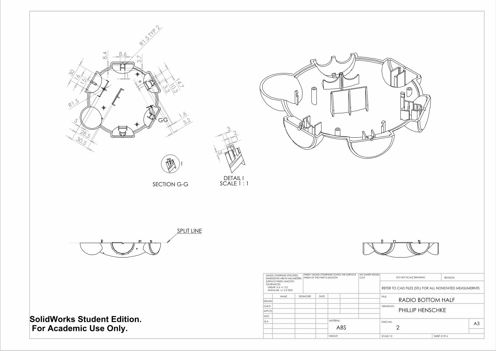
As can be seen in the picture above, the split line is on the edge of the part. This should reduce the amount of issues when coming to burs and should make the quality checking procedure faster and easier. This is the same for the bottom half of the mould as shown in the picture below:

Only the clip-fits protrude above the split line, and due to the construction of the piece is not an issue when it comes to final appearance. The other external pieces for the radio have a split line running along an external edge and therefore have no impact on the final appearance of the piece. As seen in the image above, there are undercuts in the moulding. This undercut takes form as part of the clip holding the circuit board in place. Due to its position and size, it should not be an issue and should be cast easily.
The image above shows the circuit board placement and attachment. The board is placed in the center of the radio, with the components around it. This allows for each part to be easily attached, and makes installation of the parts (and possible replacement) easy to accomplish. The board is held in place in three spots, two spots using a simple grove in a boss and the third being a clip-fit, allowing for easy installation and removal of the board. The control of the radio can also be observed from the picture above. The four dials that make up the outer shape of the radio are responsible for the control of the radio. Each dial preforms a set task by either clicking or rotating. These tasks are labeled on the top of the radio. As each component sits in its boss, only the PCB, and batteries are held down by the plastic or screws. The rest of the components shall be held in place using a small amount of hot glue, a glue that is strong enough to handle the rigors of the parts being used, while drying fast enough to be used on a production line.

The upper and lower half of the radio is fixed into place with the use of three screws. This is seen in the image below:
This was chosen to keep a clean finish between the top and bottom half of the radio. This also stops it being easily opened and changed. Due to this method of attaching the top and bottom half, it may only be opened a low number of times before the screw destroys the upper boss of the radio. This is a slight issue, but due to the components used, it should not ever have to be dismantled. If user testing finds that the radio is required to be opened more regularly, then they upper bosses shall have brass lug, to allow the screw thread to be used without self-tapping screws. The injection points for the radio are intended to be on the inside of each piece. Due to the positioning and frequency of the bosses, these would be ideal sights for the injection points, as they would not suffer from discoloration due to the stress of the manufacturing process.
As the radio’s body is constructed entirely of plastic, its free surfaces are the outward facing ones. This makes the placement of the injection points crucial to the finish of the material A slightly textured surface has been chosen for the radio to help with not only abuse in its use, but also to hide any possible issues with pitting due to the bosses.

SPLIT LINE
30
60°
120°
52
A
A
B
B
4
TYP
3 PO
SNS
SECTION A-A
50
48
R60
11.
5
11
R1 TYP 4
5.
5
3
2
3.3
2
3
25
43.
3 4
1.6
24 32.3
13.
4
4.7
1
8.7
21.
7
3
2
SECTION B-B
WEIGHT:
A3
SHEET 1 OF 6SCALE:1:2
DWG NO.
TITLE:
REVISIONDO NOT SCALE DRAWING
MATERIAL:
DATESIGNATURENAME
NO SHARP EDGES0.2 R
FINISH: UNLESS OTHERWISE STATED THE SURFACEFINISH OF THE PART IS SMOOTH
UNLESS OTHERWISE SPECIFIED:DIMENSIONS ARE IN MILLIMETERSSURFACE FINISH: SMOOTHTOLERANCES: LINEAR: X.X +/- 0.2 ANGULAR: +/- 0.2 DEG
Q.A
MFG
APPV'D
CHK'D
DRAWN
ABS
RADIO TOP HALF
REFER TO CAD FILES (STL) FOR ALL NONSTATED MEASUMERNTS
1
DRAWN BY:
PHILLIP HENSCHKESolidWorks Student Edition. For Academic Use Only.
SPLIT LINE
8.6
8.4
1
3.7
14.7
10.3
3.3
1.6
3.2
R1.5 TY
P 2
1 15 1
6 30
5 28.5 30.5
R1.5
GG
I
SECTION G-G
3 2 1
3
DETAIL I SCALE 1 : 1
WEIGHT:
A3
SHEET 2 OF 6SCALE:1:2
DWG NO.
TITLE:
REVISIONDO NOT SCALE DRAWING
MATERIAL:
DATESIGNATURENAME
Q.A
MFG
APPV'D
CHK'D
DRAWN
PHILLIP HENSCHKE
REFER TO CAD FILES (STL) FOR ALL NONSTATED MEASUMERNTS
RADIO BOTTOM HALF
ABS
UNLESS OTHERWISE SPECIFIED:DIMENSIONS ARE IN MILLIMETERSSURFACE FINISH: SMOOTHTOLERANCES: LINEAR: X.X +/- 0.2 ANGULAR: +/- 0.2 DEG
FINISH: UNLESS OTHERWISE STATED THE SURFACEFINISH OF THE PART IS SMOOTH
NO SHARP EDGES0.2 R
DRAWN BY:
2SolidWorks Student Edition. For Academic Use Only.

4 R7
R8
3
SPLIT LINE
32.
5 33
16.5 3 2
WEIGHT:
A4
SHEET 3 OF 6SCALE:1:1
DWG NO.
TITLE:
REVISIONDO NOT SCALE DRAWING
MATERIAL:
DATESIGNATURENAME
Q.A
MFG
APPV'D
CHK'D
DRAWN
PHILLIP HENSCHKEDRAWN BY:
REFER TO CAD FILES (STL) FOR ALL NONSTATED MEASUMERNTS
RADIO TOP HALF
ABS
UNLESS OTHERWISE SPECIFIED:DIMENSIONS ARE IN MILLIMETERSSURFACE FINISH: SMOOTHTOLERANCES: LINEAR: X.X +/- 0.2 ANGULAR: +/- 0.2 DEG
FINISH: UNLESS OTHERWISE STATED THE SURFACEFINISH OF THE PART IS SMOOTH
NO SHARP EDGES0.2 R
SolidWorks Student Edition. For Academic Use Only.
R7 1
R6
17
J
J
R20.3
SPLIT LINE
1.5 4
1
2
9.3 11.3
1.9
R
20.2
1
SECTION J-J
WEIGHT:
A4
SHEET 4 OF 6SCALE:1:1
DWG NO.
TITLE:
REVISIONDO NOT SCALE DRAWING
MATERIAL:
DATESIGNATURENAME
Q.A
MFG
APPV'D
CHK'D
DRAWN
PHILLIP HENSCHKE
REFER TO CAD FILES (STL) FOR ALL NONSTATED MEASUMERNTS
ABS
UNLESS OTHERWISE SPECIFIED:DIMENSIONS ARE IN MILLIMETERSSURFACE FINISH: SMOOTHTOLERANCES: LINEAR: X.X +/- 0.2 ANGULAR: +/- 0.2 DEG
FINISH: UNLESS OTHERWISE STATED THE SURFACEFINISH OF THE PART IS SMOOTH
NO SHARP EDGES0.2 R
Battery Cover
SolidWorks Student Edition. For Academic Use Only.

40.1
37
R1.
5
2
15
15
1
L
L
SPLIT LINE
66.8° 1.5
SECTION L-L
WEIGHT:
A4
SHEET 5 OF 6SCALE:1:1
DWG NO.
TITLE:
REVISIONDO NOT SCALE DRAWING
MATERIAL:
DATESIGNATURENAME
Q.A
MFG
APPV'D
CHK'D
DRAWN
PHILLIP HENSCHKEDRAWN BY:
REFER TO CAD FILES (STL) FOR ALL NONSTATED MEASUMERNTS
RADIO CLICK KNOB
ABS
UNLESS OTHERWISE SPECIFIED:DIMENSIONS ARE IN MILLIMETERSSURFACE FINISH: SMOOTHTOLERANCES: LINEAR: X.X +/- 0.2 ANGULAR: +/- 0.2 DEG
FINISH: UNLESS OTHERWISE STATED THE SURFACEFINISH OF THE PART IS SMOOTH
NO SHARP EDGES0.2 R
SolidWorks Student Edition. For Academic Use Only.

40.1
37
R2.
2
3.
3
1 10
10
M
M
SPLIT LINE
16.1°
10
1.5
SECTION M-M
A4
SHEET 6 OF 6SCALE:1:1
DWG NO.
TITLE:
REVISIONDO NOT SCALE DRAWING
MATERIAL:
DATESIGNATURENAME
Q.A
MFG
APPV'D
CHK'D
DRAWN
ABS
DRAWN BY:
RADIO TWIST KNOB
PHILLIP HENSCHKE
UNLESS OTHERWISE SPECIFIED:DIMENSIONS ARE IN MILLIMETERSSURFACE FINISH: SMOOTHTOLERANCES: LINEAR: X.X +/- 0.2 ANGULAR: +/- 0.2 DEG
NO SHARP EDGES0.2 R
FINISH: UNLESS OTHERWISE STATED THE SURFACEFINISH OF THE PART IS SMOOTH
REFER TO CAD FILES (STL) FOR ALL NONSTATED MEASUMERNTS
WEIGHT:
SolidWorks Student Edition. For Academic Use Only.

