product information wsd 81i (dry cleaner) · pdf file · 2016-10-29product...
TRANSCRIPT

Product information
WSD 81i (dry cleaner)Code No. : T0053297399
SetPower unit PUD 81i, 95 W, 230 V, with soldering iron WSP 80 (80 W, 24 V) with silver line heating technologyand safety rest WDH 10 with brass wool, includes UK and EU cordset.
Technical data
This station is ESD safe.
Dimensions L x W xH:
166 x 115 x 101 mm(6.54 x 4.53 x 3.98 inch)
Power supply: 230 V 50/60Hz;240/120 V - 50/60 Hz;120 V 60 Hz;100 V - 50/60 Hz;
Power consumption: 95 W
Protection class: I, housing antistaticIII, soldering tool
Fuse T500mA (230V, 50/60 Hz)
Temperature range: 50°C - 450°C;150°F - 850°F
Temperatureaccuracy:
± 9°C
Temperature stability: ± 2°C
Equipotentialbonding:
Via 3,5 mm pawl socket on back of device
Easy operation:●
Integrated, automatic processes and fewer operating requirements. No calibration needed (IPCcompliant).Rugged housing:●
Made from high quality, tough, antistatic materials and low wear plug and socket connectors.100% long-term performance:●
Platinum sensor technology gives precise temperature accuracy and control. Compared to otherstations, the WSD 81i offers temperature stability and accuracy without variation over time.
Digital Storage OscilloscopesTBS1000B Series Datasheet
The TBS1000B Digital Storage Oscilloscope Series provides you withaffordable performance in a compact design. Packed with standardfeatures - including USB connectivity, 34 automated measurements, limittesting, data logging, frequency counter, TrendPlot™ and a context-sensitive help menu - the TBS1000B Series oscilloscopes helps you getmore done, in less time.
Key performance specifications
200MHz, 150 MHz, 100 MHz, 70 MHz, 50 MHz, and 30 MHz 1
bandwidth models
2-channel models
Up to 2 GS/s sample rate on all channels
2.5k point record length on all channels
Advanced triggers including pulse and line-selectable video triggers
Key features
7 inch WVGA (800X480) Active TFT Color Display
34 automated measurements
Dual window FFT, simultaneously monitors both the time andfrequency domains
Built-in waveform limit and TrendPlot™ testing
Dual channel frequency counter
Zoom Function
Automated, extended data logging feature
Autoset and auto-ranging functions
Built-in context-sensitive help
Multiple-language user interface
Small footprint and lightweight - Only 4.9 in. (124 mm) deep and 4.4 lb.(2 kg)
Connectivity
USB 2.0 host port on the front panel for quick and easy data storage
USB 2.0 device port on rear panel for easy connection to a PC
Seeing signal detailsTo properly analyze signals you need to make sure that you can see themin enough detail. The TBS1000B comes standard with a 7-inch highresolution TFT display for a clear view of all of your signals and critical onscreen information. The instrument is further enhanced by a user interfaceinspired by the award winning Tektronix MSO/DPO series of instruments.The interface is easy to use, provides quick access to all of the oscilloscopefunctions and includes a high resolution "Pan & Zoom" feature enabling youto see even more signal details of up to 10 times normal resolution.
The zoom function shows details in an event of up to 10X the normal view.
1 30 MHz model available only in North America and Europe.
www.tektronix.com 1

Digital precision for accurate measurementsWith up to 200 MHz bandwidth, 2 GS/s maximum sample rate and 3%vertical measurement accuracy the TBS1000B allows you to see the detailsof your signals. With the Tektronix proprietary sampling technology thereare no compromises, you will get the stated real-time sampling rate on allchannels, all the time with at least of 10X oversampling. The samplingperformance is not reduced when changing horizontal settings or whenusing multiple channels, enabling you to see the true characteristics of yoursignals.
See all the details other oscilloscopes might miss with Tektronix proprietary digital real-time sampling.
Critical tools for troubleshooting your deviceThe TBS1000B oscilloscope comes standard with a variety of advancedtriggers used to debug today's complex circuitry. Flexible options forutilizing rising or falling edges, pulse widths and video trigger set-upsenable users to quickly isolate their signals of interest.
The pulse trigger function can easily capture critical events.
Once signals are captured, the TBS1000B offers advanced math andmeasurement capabilities making it easy to evaluate signal quality . Userscan add, subtract and multiply waveforms or use any one of 34 automatedmeasurements to quickly and reliably calculate important signalcharacteristics such as frequency, rise time or overshoot.
Quickly analyze signals with the standard 34 automated measurements.
A dedicated front panel button provides quick access to the FFT functionthat is capable of showing both frequency and time domain waveformssimultaneously, which provides a convenient way to see the relationshipbetween signals and the FFT results.
Quickly perform an FFT with a dedicated front panel button.
For accurate frequency measurements the TBS1000B also comes withbuilt-in dual channel frequency counters. Independent control of eachcounter's trigger level provides an easy way to monitor two different signalfrequencies simultaneously.
Dual channel - 6 digit frequency counters come standard with all TBS1000 models.
Datasheet
2 www.tektronix.com
Extensive monitoring and analysis toolsIntermittent faults can be hard to evaluate, simply because they do notrepeat often making them difficult to capture. The TrendPlot™ functionhelps find those faults by plotting measurement values over long periods oftime. Select the measurement to capture on either or both channels andthen set-up the oscilloscope to continuously monitor those measurements,plot the data on the display and simultaneously save the information to aUSB thumb drive. Depending on the oscilloscope setting, you'll be able tocapture data for minutes, hours or even days; the only limitation is the sizeof the thumb drive.
To find intermittent faults the TrendPlot ™ function can monitor measurements for longperiods of time.
Often, only Pass/Fail data is needed to determine if a signal is good. Thiscan be accomplished easily with the TBS1000B Limit Test feature. Theoscilloscope can be set-up to automatically monitor a source signals andoutput Pass or Fail results by evaluating whether the acquired waveformfalls within predefined boundaries. The TBS1000B Limit Test feature allowsusers to create templates based on one or two independent referencewaveforms, providing more flexibility when creating masks for complexsignals. If a failure is detected, a series of specific actions can be triggeredwhich include; stopping waveform acquisition, halting Limit Test functions,saving a screen image of the failed waveform, or any combination of theabove.
The Limit Test feature provides a quick Pass/Fail comparison between any triggeredinput signal and a user- defined template.
Flexible data transferThe USB host port on the front panel enables you to save your instrumentsettings, screenshots, and waveform data onto a USB memory device. Thisport also supports the built-in Data Logging feature which enables you toset up the oscilloscope to save user- specified triggered waveforms to aUSB device for up to 24 hours. You can also select the "Infinite" option forcontinuous waveform monitoring. In the infinite mode you can save yourtriggered waveforms to an external USB memory device without a durationlimitation until the memory device is full. The oscilloscope will then guideyou to insert another USB memory device to continue saving waveforms.
Data logging enables automatic saving of triggered waveforms.
Designed to make your work easyThe TBS1000B series oscilloscopes are designed with the ease of use andfamiliar operation you have come to expect from Tektronix.
Intuitive operationThe intuitive user interface with dedicated per-channel vertical controls,auto-setup, and auto-ranging makes these instruments easy to use,reducing learning time and increasing efficiency.
TBS1000B Digital Storage Oscilloscopes
www.tektronix.com 3

Help when you need it, where you need itThe built-in Help menu provides you with important information about youroscilloscope's features and functions. Help is provided in the samelanguages as the user interface.
The context-sensitive help system provides important information specific to the task youare working on.
Performance you can count onIn addition to industry-leading service and support, every TBS1000B seriesoscilloscope comes backed with a 5-year warranty as standard.
Datasheet
4 www.tektronix.com
SpecificationsAll specifications apply to all models unless noted otherwise.
Model overview
TBS1032B 2 TBS1052B TBS1072B TBS1102B TBS1152B TBS1202BBandwidth 30 MHz 50 MHz 70 MHz 100 MHz 150 MHz 200 MHzChannels 2 2 2 2 2 2 Sample rate on each channel 500 MS/s 1.0 GS/s 1.0 GS/s 2 .0 GS/s 2 .0 GS/s 2 .0 GS/sRecord length 2.5k points at all-time bases
Vertical system – Analog channels
Vertical resolution 8 bits
Input sensitivity range 2 mV to 5 V/div on all models with calibrated fine adjustment
DC gain accuracy ±3%, from 10 mV/div to 5 V/div
Maximum input voltage 300 VRMS CAT II; derated at 20 dB/decade above 100 kHz to 13 Vp-p AC at 3 MHz and above
Offset range 2 mV to 200 mV/div: ±1.8 V
>200 mV to 5 V/div: ±45 V
Bandwidth limit 20 MHz
Input coupling AC, DC, GND
Input impedance 1 MΩ in parallel with 20 pF
Vertical zoom Vertically expand or compress a live or stopped waveform
Horizontal system — Analog channels
Time base range30 MHz model 3 10 ns to 50 s/div50 MHz and 70 MHz models 5 ns to 50 s/div100MHz, 150MHz and 200MHzmodels
2.5 ns to 50 s/div
Time base accuracy 50 ppm
Horizontal zoom Horizontally expand or compress a live or stopped waveform
2 Available only in North America and Europe.
3 Available only in North America and Europe.
TBS1000B Digital Storage Oscilloscopes
www.tektronix.com 5
Input/Output ports
USB interface USB host port on front panel supports USB flash drives USB device port on back of instrument supports connection to PC and allPictBridge®-compatible printers
GPIB interface Optional
Data storage
Nonvolatile storageReference waveform display 2.5K point reference waveformsWaveform storage withoutUSB flash drive
2.5K point
Maximum USB flash drive size 64 GBWaveform storage with USBflash drive
96 or more reference waveforms per 8 MB
Setups without USB flashdrive
10 front-panel setups
Setups with USB flash drive 4000 or more front-panel setups per 8 MBScreen images with USB flashdrive
128 or more screen images per 8 MB (the number of images depends on file format selected)
Save All with USB flash drive 12 or more Save All operations per 8 MB
A single Save All operation creates 3 to 9 files (setup, image, plus one file for each displayed waveform)
Acquisition system
Acquisition modesPeak Detect High-frequency and random glitch capture. Captures glitches as narrow as 12 ns (typical) at all time base settings from 5 μs/div to
50 s/divSample Sample data onlyAverage Waveform averaged, selectable: 4, 16, 64, 128 Single Sequence Use the Single Sequence button to capture a single triggered acquisition sequenceRoll At acquisition time base settings of >100 ms/div
Trigger system
External trigger input Included on all models
Trigger modes Auto, Normal, Single Sequence
Trigger typesEdge (Rising/Falling) Conventional level-driven trigger. Positive or negative slope on any channel. Coupling selections: AC, DC, Noise Reject, HF
Reject, LF RejectVideo Trigger on all lines or individual lines, odd/even or all fields from composite video, or broadcast standards (NTSC, PAL, SECAM)Pulse Width (or Glitch) Trigger on a pulse width less than, greater than, equal to, or not equal to, a selectable time limit ranging from 33 ns to 10 s
Trigger source Two channel models: CH1, CH2, Ext, Ext/5, AC Line
Trigger view Displays trigger signal while Trigger View button is depressed.
Trigger signal frequency readout Provides a frequency readout of the trigger source.
Datasheet
6 www.tektronix.com
Waveform measurements
CursorsTypes Amplitude, TimeMeasurements ΔT, 1/ΔT, ΔV
Automatic measurements Period, Frequency, Pos Width, Neg Width, Rise Time, Fall Time, Maximum , Minimum , Peak-Peak, Mean, RMS, Cycle RMS,Cursor RMS, Phase, Pos Pulse Cnt, Neg Pulse Cnt, Rise Edge Cn, Fall Edge Cn, Pos Duty, Neg Duty, Amplitude, Cycle Mean,Cursor Mean, Burst Width, Pos Overshoot, Neg Overshoot, Area, Cycle Area, High, Low, Delay RR, Delay RF, Delay FR, DelayFF
Waveform math
Arithmetic Add, Subtract, Multiply
Math functions FFT
FFT Windows: Hanning, Flat Top, Rectangular 2048 sample points
Sources Two channel models: CH1 - CH2, CH2 - CH1, CH1 + CH2, CH1 × CH2
Autoset
Autoset menu Single-button, automatic setup of all channels for vertical, horizontal, and trigger systems, with undo AutosetSquare wave Single Cycle, Multicycle, Rising or Falling EdgeSine wave Single Cycle, Multicycle, FFT SpectrumVideo (NTSC, PAL, SECAM) Field: All, Odd, or Even Line: All or Selectable Line Number
Autorange
Automatically adjust vertical and/or horizontal oscilloscope settings when probe is moved from point to point, or when the signalexhibits large changes.
Frequency counter
Resolution 6 digits
Accuracy (typical) + 51 parts per million including all frequency reference errors and +1 count errors
Frequency range AC coupled, 10 Hz minimum to rated bandwidth
Frequency counter signal source Pulse width or edge selected trigger source
Frequency counter measures selected trigger source at all times in pulse width and edge mode, including when the oscilloscopeacquisition is halted due to changes in run status, or acquisition of a single shot event has completed.
The frequency counter does not measure pulses that do not qualify as legitimate trigger events.
Pulse Width mode: Counts pulses of enough magnitude inside the 250 ms measurement window that qualify as triggerable events(e.g. all narrow pulses in a PWM pulse train if set to "<" mode and the limit is set to a relatively small number).
Edge Trigger mode: Counts all pulses of enough magnitude.
Channels 2 channel
TBS1000B Digital Storage Oscilloscopes
www.tektronix.com 7
Display system
Interpolation Sin (x)/x
Waveform styles Dots, vectors
Persistence Off, 1 s, 2 s, 5 s, infinite
Format YT and XY
Power source
Power source voltage 100 to 240 V ±10%
Power source frequency100 V to 240 V 50 Hz to 60 Hz115 V 400 Hz ±10%
Power consumption 30 W maximum
Physical characteristics
Dimensions mm in.Height 158.0 6.22 Width 326.3 12.85 Depth 124.2 4.89
Shipping dimensions mm in.Height 266.7 10.5 Width 476.2 18.75 Depth 228.6 9.0
Weight kg lb.Instrument only 2.0 4.3 ...with accessories 2.2 4.9
RM2000B rackmount mm inWidth 482.6 19.0 Height 177.8 7.0 Depth 108.0 4.25
Datasheet
8 www.tektronix.com

Environmental
TemperatureOperating 0 to +50 ºCNonoperating –40 to +71 ºC
HumidityOperating and nonoperating Up to 85% RH at or below +40 ºC
Up to 45% RH up to +50 ºC
AltitudeOperating and nonoperating Up to 3,000 m (9,843 ft.)
RegulatoryElectromagnetic compatibility Meets Directive 2004/108/EC, EN 61326-2-1 Class A; Australian EMC FrameworkSafety UL61010-1:2004, CSA22.2 No. 61010-1:2004, EN61010-1:2001, IEC61010-1:2001
TBS1000B Digital Storage Oscilloscopes
www.tektronix.com 9
Ordering information
ModelsTBS1032B 4 30 MHz, 2 Ch, 500 MS/s, TFT DSO
TBS1052B 50 MHz, 2 Ch, 1 GS/s, TFT DSO
TBS1072B 70 MHz, 2 Ch, 1 GS/s, TFT DSO
TBS1102B 100 MHz, 2 Ch, 2 GS/s, TFT DSO
TBS1152B 150 MHz, 2 Ch, 2 GS/s, TFT DSO
TBS1202B 200 MHz, 2 Ch, 2 GS/s, TFT DSO
Language options
Opt. L1 French overlay
Opt. L2 Italian overlay
Opt. L3 German overlay
Opt. L4 Spanish overlay
Opt. L5 Japanese overlay 5
Opt. L6 Portuguese overlay
Opt. L7 Simplified Chinese overlay 5
Opt. L8 Traditional Chinese overlay 5
Opt. L9 Korean overlay 5
Opt. L10 Russian overlay
Power plug optionsOptions A3, A6, A10, A11 and A12 are not available on the TBS1032B model.
Opt. A0 North America power plug (115 V, 60 Hz)
Opt. A1 Universal Euro power plug (220 V, 50 Hz)
Opt. A2 United Kingdom power plug (240 V, 50 Hz)
Opt. A3 Australia power plug (240 V, 50 Hz)
Opt. A5 Switzerland power plug (220 V, 50 Hz)
Opt. A6 Japan power plug (100 V, 50/60 Hz)
Opt. A10 China power plug (50 Hz)
Opt. A11 India power plug (50 Hz)
4 Available only in North America and Europe.
5 Not available with the TBS1032B model.
Datasheet
10 www.tektronix.com

Opt. A12 Brazil power plug (60 Hz)
Opt. A99 No power cord
Service options
Opt. D1 Calibration Data Report
Probes and accessories are not covered by the oscilloscope warranty and Service Offerings. Refer to the datasheet of each probe and accessory model for its unique warrantyand calibration terms.
Probe option
TBS1XX2B P2220 Replaces standard probes with P2220 probes (200 MHz passive voltage probes with 1x/ 10x attenuation)
Standard accessories
Accessory DescriptionPassive probes, one per channel TPP0051: 50MHz passive probe for: TBS1032B 6, TBS1052B
TPP0101: 100 MHz passive probe for: TBS1072B, TBS1102BTPP0201: 200 MHz passive probe for: TBS1152B, TBS1202B
Power cord (Please specify plug option)NIM/NIST Traceable certificate of calibrationPrinted documentation Installation and safety manual
(English, Japanese, and Simplified Chinese)CD with customer documentation Customer documentation including detailed user manuals (English, French, German, Italian, Japanese, Korean,
Portuguese, Russian, Simplified Chinese, Spanish, Traditional Chinese)5-year warranty Covers labor and parts for defects in materials and workmanship for 5 years, excluding probes and accessories
(probes and accessories are not covered by the oscilloscope warranty and service offerings. refer to the data sheetof each probe and accessory model for its unique warranty and calibration terms)
Recommended accessories
Accessory DescriptionTEK-USB-488 GPIB-to-USB converterAC2100 Soft carrying case for instrumentHCTEK4321 Hard plastic carrying case for instrument (requires AC2100)RM2000B Rackmount kit077-0444-xx Programmer manual – English only077-0772-xx Service manual – English only174-4401-xx USB host to device cable, 3 ft. long
6 Available only in North America and Europe.
TBS1000B Digital Storage Oscilloscopes
www.tektronix.com 11
Recommended probes
Probe DescriptionTPP0051 10X passive probe, 50 MHz bandwidthTPP0101 10X passive probe, 100 MHz bandwidthTPP0201 10X passive probe, 200 MHz bandwidthP2220 1X/10X passive probe, 200 MHz bandwidthP6101B 1X passive probe (15 MHz, 300 V RMS CAT II rating)P6015A 1000X high-voltage passive probe (75 MHz)P5100A 100X high-voltage passive probe (500 MHz)P5200A 50 MHz, 50X/500X high-voltage differential probeP6021A 15 A, 60 MHz AC current probeP6022 6 A, 120 MHz AC current probeA621 2000 A, 5 to 50 kHz AC current probeA622 100 A, 100 kHz AC/DC current probe/BNCTCP303/TCPA300 150 A, 15 MHz AC/DC current probe/amplifierTCP305A/TCPA300 50 A, 50 MHz AC/DC current probe/amplifierTCP312A/TCPA300 30 A, 100 MHz AC/DC current probe/amplifierTCP404XL/TCPA400 500 A, 2 MHz AC/DC current probe/amplifier
Tektronix is registered to ISO 9001 and ISO 14001 by SRI Quality System Registrar.
Product(s) complies with IEEE Standard 488.1-1987, RS-232-C, and with Tektronix Standard Codes and Formats.
Datasheet
ASEAN / Australasia (65) 6356 3900 Austria 00800 2255 4835* Balkans, Israel, South Africa and other ISE Countries +41 52 675 3777 Belgium 00800 2255 4835* Brazil +55 (11) 3759 7627 Canada 1 800 833 9200 Central East Europe and the Baltics +41 52 675 3777 Central Europe & Greece +41 52 675 3777 Denmark +45 80 88 1401 Finland +41 52 675 3777 France 00800 2255 4835* Germany 00800 2255 4835*Hong Kong 400 820 5835 India 000 800 650 1835 Italy 00800 2255 4835*Japan 81 (3) 6714 3010 Luxembourg +41 52 675 3777 Mexico, Central/South America & Caribbean 52 (55) 56 04 50 90 Middle East, Asia, and North Africa +41 52 675 3777 The Netherlands 00800 2255 4835* Norway 800 16098 People's Republic of China 400 820 5835 Poland +41 52 675 3777 Portugal 80 08 12370 Republic of Korea 001 800 8255 2835 Russia & CIS +7 (495) 6647564 South Africa +41 52 675 3777 Spain 00800 2255 4835* Sweden 00800 2255 4835* Switzerland 00800 2255 4835*Taiwan 886 (2) 2656 6688 United Kingdom & Ireland 00800 2255 4835* USA 1 800 833 9200
* European toll-free number. If not accessible, call: +41 52 675 3777
For Further Information. Tektronix maintains a comprehensive, constantly expanding collection of application notes, technical briefs and other resources to help engineers working on the cutting edge of technology. Please visit www.tektronix.com.
Copyright © Tektronix, Inc. All rights reserved. Tektronix products are covered by U.S. and foreign patents, issued and pending. Information in this publication supersedes that in all previously published material. Specification andprice change privileges reserved. TEKTRONIX and TEK are registered trademarks of Tektronix, Inc. All other trade names referenced are the service marks, trademarks, or registered trademarks of their respective companies.
18 Sep 2015 3GW-30004-3
www.tektronix.com
DC
PO
WE
R S
UP
PLI
ES
A Greater Measure of Confidencewww.keithley.com
1.888.KEITHLEY (U.S. only)
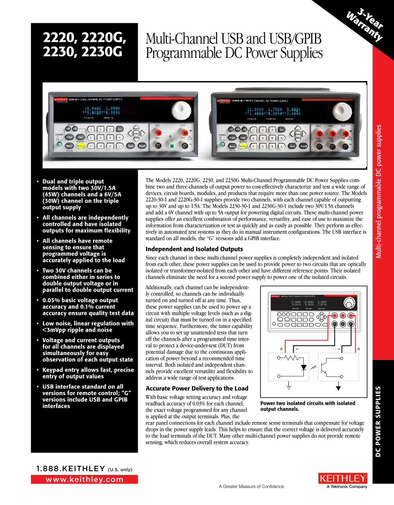
The Models 2220, 2220G, 2230, and 2230G Multi-Channel Programmable DC Power Supplies com-bine two and three channels of output power to cost-effectively characterize and test a wide range of devices, circuit boards, modules, and products that require more than one power source. The Models 2220-30-1 and 2220G-30-1 supplies provide two channels, with each channel capable of outputting up to 30V and up to 1.5A. The Models 2230-30-1 and 2230G-30-1 include two 30V/1.5A channels and add a 6V channel with up to 5A output for powering digital circuits. These multi-channel power supplies offer an excellent combination of performance, versatility, and ease of use to maximize the information from characterization or test as quickly and as easily as possible. They perform as effec-tively in automated test systems as they do in manual instrument configurations. The USB interface is standard on all models; the “G” versions add a GPIB interface.
Independent and Isolated OutputsSince each channel in these multi-channel power supplies is completely independent and isolated from each other, these power supplies can be used to provide power to two circuits that are optically isolated or transformer-isolated from each other and have different reference points. Their isolated channels eliminate the need for a second power supply to power one of the isolated circuits.
Additionally, each channel can be independent-ly controlled, so channels can be individually turned on and turned off at any time. Thus, these power supplies can be used to power up a circuit with multiple voltage levels (such as a dig-ital circuit) that must be turned on in a specified time sequence. Furthermore, the timer capability allows you to set up unattended tests that turn off the channels after a programmed time inter-val to protect a device-under-test (DUT) from potential damage due to the continuous appli-cation of power beyond a recommended time interval. Both isolated and independent chan-nels provide excellent versatility and flexibility to address a wide range of test applications.
Accurate Power Delivery to the LoadWith basic voltage setting accuracy and voltage readback accuracy of 0.03% for each channel, the exact voltage programmed for any channel is applied at the output terminals. Plus, the rear panel connections for each channel include remote sense terminals that compensate for voltage drops in the power supply leads. This helps to ensure that the correct voltage is delivered accurately to the load terminals of the DUT. Many other multi-channel power supplies do not provide remote sensing, which reduces overall system accuracy.
• Dual and triple output models with two 30V/1.5A (45W) channels and a 6V/5A (30W) channel on the triple output supply
• All channels are independently controlled and have isolated outputs for maximum flexibility
• All channels have remote sensing to ensure that programmed voltage is accurately applied to the load
• Two 30V channels can be combined either in series to double output voltage or in parallel to double output current
• 0.03% basic voltage output accuracy and 0.1% current accuracy ensure quality test data
• Low noise, linear regulation with <3mVpp ripple and noise
• Voltage and current outputs for all channels are displayed simultaneously for easy observation of each output state
• Keypad entry allows fast, precise entry of output values
• USB interface standard on all versions for remote control; “G” versions include USB and GPIB interfaces
2220, 2220G,2230, 2230G
Multi-Channel USB and USB/GPIB Programmable DC Power Supplies
+ +– –
2230-30-1 TRIPLE CHANNEL DC POWER SUPPLY
CH1 0-30V CH2 0-30V CH3 0-5.5V
Power two isolated circuits with isolated output channels.
3-Year
Warranty
Mul
ti-ch
anne
l pro
gram
mab
le D
C po
wer
sup
plie
s
Mul
ti-ch
anne
l pro
gram
mab
le D
C po
wer
sup
plie
s
DC
PO
WE
R S
UP
PLI
ES
www.keithley.com
1.888.KEITHLEY (U.S. only)
A Greater Measure of Confidence
2220, 2220G,2230, 2230G
Multi-Channel USB and USB/GPIB Programmable DC Power Supplies
Great accuracy is not limited to voltage; the basic current setting and readback accuracy is 0.1%, pro-viding high quality load current measurements. Also, with less than 3mV p-p noise, the power applied to the DUT’s load terminals is both accurate and of high quality.
Excellent accuracy, remote sensing, and a wide power output range make the Series 2200 Multi-Channel DC Power Supplies essential test instruments both on the bench and in test systems. Their ability to generate a wide range of output power and measure a wide range of load currents is supported with:
• Maximum output power of 45W on the 30V channels • Maximum output power of 30W on the 6V channel• Voltage setting and reading resolution of 1mV • Current setting and reading resolution of 1mA
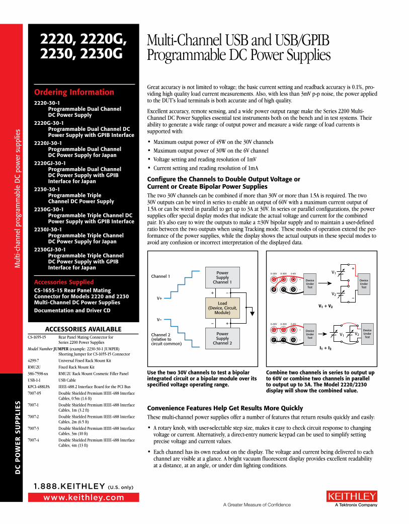
Configure the Channels to Double Output Voltage or Current or Create Bipolar Power SuppliesThe two 30V channels can be combined if more than 30V or more than 1.5A is required. The two 30V outputs can be wired in series to enable an output of 60V with a maximum current output of 1.5A or can be wired in parallel to get up to 3A at 30V. In series or parallel configurations, the power supplies offer special display modes that indicate the actual voltage and current for the combined pair. It’s also easy to wire the outputs to make a ±30V bipolar supply and to maintain a user-defined ratio between the two outputs when using Tracking mode. These modes of operation extend the per-formance of the power supplies, while the display shows the actual outputs in these special modes to avoid any confusion or incorrect interpretation of the displayed data.
Convenience Features Help Get Results More QuicklyThese multi-channel power supplies offer a number of features that return results quickly and easily:
• A rotary knob, with user-selectable step size, makes it easy to check circuit response to changing voltage or current. Alternatively, a direct-entry numeric keypad can be used to simplify setting precise voltage and current values.
• Each channel has its own readout on the display. The voltage and current being delivered to each channel are visible at a glance. A bright vacuum fluorescent display provides excellent readability at a distance, at an angle, or under dim lighting conditions.
Ordering Information2220-30-1
Programmable Dual Channel DC Power Supply
2220G-30-1 Programmable Dual Channel DC Power Supply with GPIB Interface
2220J-30-1 Programmable Dual Channel DC Power Supply for Japan
2220GJ-30-1 Programmable Dual Channel DC Power Supply with GPIB Interface for Japan
2230-30-1 Programmable Triple Channel DC Power Supply
2230G-30-1 Programmable Triple Channel DC Power Supply with GPIB Interface
2230J-30-1 Programmable Triple Channel DC Power Supply for Japan
2230GJ-30-1 Programmable Triple Channel DC Power Supply with GPIB Interface for Japan
Accessories SuppliedCS-1655-15 Rear Panel Mating Connector for Models 2220 and 2230 Multi-Channel DC Power SuppliesDocumentation and Driver CD
ACCeSSORIeS AVAILABLeCS-1655-15 Rear Panel Mating Connector for
Series 2200 Power SuppliesModel Number JUMPER (example: 2230-30-1 JUMPER)
Shorting Jumper for CS-1655-15 Connector4299-7 Universal Fixed Rack Mount KitRMU2U Fixed Rack Mount Kit386-7598-xx RMU2U Rack Mount Cosmetic Filler PanelUSB-1-1 USB CableKPCI-488LPA IEEE-488.2 Interface Board for the PCI Bus7007-05 Double Shielded Premium IEEE-488 Interface
Cables, 0.5m (1.6 ft)7007-1 Double Shielded Premium IEEE-488 Interface
Cables, 1m (3.2 ft)7007-2 Double Shielded Premium IEEE-488 Interface
Cables, 2m (6.5 ft)7007-3 Double Shielded Premium IEEE-488 Interface
Cables, 3m (10 ft)7007-4 Double Shielded Premium IEEE-488 Interface
Cables, 4m (13 ft)
V+
Channel 1PowerSupply
Channel 1
Load(Device, Circuit,
Module)
PowerSupply
Channel 2
+
+
–
–
Channel 2(relative tocircuit common)
V–
Use the two 30V channels to test a bipolar integrated circuit or a bipolar module over its specified voltage operating range.
0-30V 0-30V 0-6V
+
–
DeviceUnderTest
V1
V1 + V2
+
V2–
0-30V 0-30V 0-6V
+
–
DeviceUnderTest
V1
I1 + I2
V2
DeviceUnderTest
DeviceUnderTest
Combine two channels in series to output up to 60V or combine two channels in parallel to output up to 3A. The Model 2220/2230 display will show the combined value.
Mul
ti-ch
anne
l pro
gram
mab
le D
C po
wer
sup
plie
s
Mul
ti-ch
anne
l pro
gram
mab
le D
C po
wer
sup
plie
s

DC
PO
WE
R S
UP
PLI
ES
A Greater Measure of Confidencewww.keithley.com
1.888.KEITHLEY (U.S. only)
2220, 2220G,2230, 2230G
Multi-Channel USB and USB/GPIB Programmable DC Power Supplies
Specifications2230-30-1, 2230J-30-1,
2230G-30-1, 2230GJ-30-12220-30-1, 2220J-30-1,
2220G-30-1, 2220GJ-30-1DC OUTPUT RATInGVoltage 0 to 30 V 0 to 30 V 0 to 6 V 0 to 30 V 0 to 30 V
Current 0 to 1.5 A 0 to 1.5 A 0 to 5 A 0 to 1.5 A 0 to 1.5 A
MAxIMUM POWeR 120 W 90 W
LOAD ReGULATIOnVoltage < 0.01% + 3 mV < 0.01% + 3 mV < 0.01% + 3 mV < 0.01% + 3 mV < 0.01% + 3 mV
Current < 0.01% + 3 mA < 0.01% + 3 mA < 0.01% + 3 mA < 0.01% + 3 mA < 0.01% + 3 mA
LIne ReGULATIOnVoltage < 0.01% + 3 mV < 0.01% + 3 mV < 0.01% + 3 mV < 0.01% + 3 mV < 0.01% + 3 mV
Current < 0.1% + 3 mA < 0.1% + 3 mA < 0.1% + 3 mA < 0.1% + 3 mA < 0.1% + 3 mA
RIPPLe AnD nOISe
Voltage (7MHz)< 1 mV rms< 3 mV p-p
< 1 mV rms< 3 mV p-p
< 1 mV rms< 3 mV p-p
< 1 mV rms< 3 mV p-p
< 1 mV rms< 3 mV p-p
Current (20MHz) < 5 mA rms < 5 mA rms < 6 mA rms < 5 mA rms < 5 mA rms
SeTTInG ReSOLUTIOnVoltage 1 mV 1 mV 1 mV 1 mV 1 mV
Current 1 mA 1 mA 1 mA 1 mA 1 mA
SeTTInG ACCURACyVoltage ± 0.03% + 10 mV ± 0.03% + 10 mV ± 0.03% + 10 mV ± 0.03% + 10 mV ± 0.03% + 10 mV
Current ± 0.1% + 5 mA ± 0.1% + 5 mA ± 0.1% + 5 mA ± 0.1% + 5 mA ± 0.1% + 5 mA
MeTeR ReSOLUTIOn Voltage 1 mV 1 mV 1 mV 1 mV 1 mV
Current 1 mA 1 mA 1 mA 1 mA 1 mA
MeTeR ACCURACyVoltage ± 0.03% + 10 mV ± 0.03% + 10 mV ± 0.03% + 10 mV ± 0.03% + 10 mV ± 0.03% + 10 mV
Current ± 0.1% + 5 mA ± 0.1% + 5 mA ± 0.1% + 5 mA ± 0.1% + 5 mA ± 0.1% + 5 mA
• To save time when repeating tests, instrument settings can be saved in one of 30 internal memory locations by simply pressing the Save button. To recall that setting, just push the Recall button, and choose the desired setup.
Protection for your Device-Under-TestThese multi-channel power supplies include maximum voltage settings that prevent volt-age from being accidentally adjusted above user-specified limits. Independent outputs allow a different limit to be specified for each output channel. With the numeric keypad, a current limit can be quickly and precisely specified before a test is started. In addition, a user- definable password allows the front panel to be locked to prevent unwanted adjustment during critical tests.
easy Test AutomationTwo interface choices are available to enable PC control from a user-preferred programming environment. A USB TMC-compliant device port is included on all versions of these power sup-plies. The “G” versions add the GPIB interface for the flexibility of either USB or GPIB control. LabView and IVI drivers are provided to facilitate instrument control, data logging, and analysis. With these drivers, the power supplies can be controlled from most commercially-available software packages such as MatLab. Thus, these power supplies can be controlled as a single unit or as part of an automated test system.
APPLICATIOnS
Typical applications include:• Circuit design• electrial engineering student labs• Materials research• Automated test
IsolatIon VoltagE, oUtPUt to CHassIs: Any output can be floated up to 240V (DC + peak AC with AC limited to a maximum of 3Vpk-pk and a maximum frequency of 60Hz) relative to earth ground terminal.
IsolatIon VoltagE, oUtPUt to oUtPUt: Any output can be floated up to 240V (DC + peak AC with AC limited to a maximum of 3Vpk-pk and a maximum frequency of 60Hz) relative to any other output terminal.
VoltagE tRansIEnt REsPonsE sEttlIng tIME, load CHangE (typical): <150ms to within 75mV following a change from 0.1A to 1A.
VoltagE tRansIEnt REsPonsE sEttlIng tIME, sEttIng CHangE, RIsIng (typical): <150ms to within 75mV following a change from 1V to 11V into a 10W resistor (Ch. 1, 2); from 0.4V to 4V into a 4W resistor (ch. 3.)
VoltagE tRansIEnt REsPonsE sEttlIng tIME, sEttIng CHangE, FallIng (typical): <150ms to within 75mV following a change from 11V to 1V into a 10W resistor (Ch. 1, 2); from 0.4V to 4V into a 4W resistor (ch. 3.)
dIsPlay: Vacuum fluorescent display.
MEMoRy: 30 setup memories.
tRaCkIng and CoMbInatIon ModEs:tracking Mode: Maintains the ratio on the two 30V output
channels that is present when the control is activated.Combination V1+V2 series Mode: Deliver up to 60 V when
CH1 and CH2 are wired in series. Meter reads back com-bined voltage.
Combination I1+12 Parallel Mode: Deliver up to 3 A when CH1 and CH2 are wired in parallel. Meter reads back combined current.
REaR PanEl ConnECtIons: USB Device Port, Type B connector, USBTMC compatible. 2220G and 2230G versions include a GPIB interface, IEEE-488.2 compliant.
POWeR SOURCeaC InPUt: Non-“J” versions: Switchable between 120VAC or
240VAC, nominal (different fuse required for each voltage). “J” Versions: 100VAC, nominal.
FREQUEnCy: 50/60Hz
PowER ConsUMPtIon: Dual Channel Versions: 350VA. Triple Channel Versions: 450VA.
PHySICAL CHARACTeRISTICSPRotECtIVE boots and HandlE InstallEd:
Height: 105.3mm (4.15 in.)width: 241.8mm (9.52 in.)depth: 384.0mm (15.12 in.)
PRotECtIVE boots and HandlE REMoVEd:Height: 90.7mm (3.57 in.)width: 217.2mm (8.55 in.)depth: 361.6mm (14.24 in.)
nEt wEIgHt: 2220-30-1: 8.2 kg (18 lb.) 2230-30-1: 8.5 kg (19 lb.)
sHIPPIng wEIgHt: 2220-30-1: 11 kg (24 lb.) 2230-30-1: 11 kg (24 lb.)
SeRVICeS AVAILABLeModel Number*-EW 1 additional year of factory warrantyModel Number-5Y-EW 2 additional years of factory warranty beyond the standard 3-year warrantyC/Model Number-3Y-STD 3 calibrations within 3 years of purchaseC/Model Number-3Y-DATA 3 (ANSI-Z540-1 compliant) calibrations within 3 years of purchaseC/Model Number-5Y-STD 5 calibrations within 5 years of purchaseC/Model Number-5Y-DATA 5 (ANSI-Z540-1 compliant) calibrations within 5 years of purchase
* Replace “Model Number” with a power supply model number. For example: if the 2230GJ-30-1 is selected, then the part number for the -EW, one year of additional warranty option, is 2230GJ-30-1-EW.
NOTE: the “J” versions truncate the “A” in DATA. Example: C/222GJ-30-1-3Y-dat
Mod
els
2220
and
223
0 sp
ecifi
catio
ns
Mod
els
2220
and
223
0 sp
ecifi
catio
ns

DC
PO
WE
R S
UP
PLI
ES
enVIROnMenTAL AnD SAFeTyTemperature: operating: 0° to +40°C.
storage: –20° to +70°C.
Relative Humidity (non-condensing):
Operating: 5% to 95% relative humidity at up to +40°C.
Storage: 5% to 95% relative humidity at up to +40°C. 5% to 60% RH above +40°C up to +70°C, non condensing.
Altitude:Operating: Up to 2000m.Storage: Up to 4000m.
Safety:European Union: Complies with European Union EMC Directive.USA: Nationally recognized testing laboratory listing UL61010-1-2004.Canada: CAN/CSA C22.2 No. 61010-1 2004.
eLeCTROMAGneTIC COMPATIBILITyEuropean Union: Complies with European Union Low Voltage Directive.
Australia: EMC Framework, demonstrated per Emission Standard AS/NZS 2064 (Industrial, Scientific, and Medical Equipment).
2220, 2220G,2230, 2230G
Multi-Channel USB and USB/GPIB Programmable DC Power Supplies
Model 2220-30-1 rear panel. The Model 2220G-30-1 adds a GPIB connector.
Model 2230G-30-1 rear panel. The Model 2230-30-1 does not have the GPIB connector.
Specifications are subject to change without notice. All Keithley trademarks and trade names are the property of Keithley Instruments, Inc.
All other trademarks and trade names are the property of their respective companies.
KEITHLEY INSTRUMENTS, INC. ■ 28775 AURORA RD. ■ CLEVELAND, OH 44139-1891 ■ 440-248-0400 ■ Fax: 440-248-6168 ■ 1-888-KEITHLEY ■ www.keithley.com
A Greater Measure of Confidence
BENELUX+31-40-267-5506www.keithley.nl
BRAZIL55-11-4058-0229www.keithley.com
CHINA86-10-8447-5556www.keithley.com.cn
FRANCE+33-01-69-86-83-60www.keithley.fr
GERMANY+49-89-84-93-07-40www.keithley.de
INDIA080-30792600www.keithley.in
ITALY+39-049-762-3950www.keithley.it
JAPAN81-120-441-046www.keithley.jp
KOREA82-2-6917-5000www.keithley.co.kr
MALAYSIA 60-4-643-9679 www.keithley.com
MEXICO 52-55-5424-7907 www.keithley.com
RUSSIA +7-495-664-7564 www.keithley.ru
SINGAPORE01-800-8255-2835www.keithley.com.sg
TAIWAN886-3-572-9077www.keithley.com.tw
UNITEDKINGDOM+44-1344-39-2450www.keithley.co.uk
For further information on how to purchase or to locate a sales partner please visit www.keithley.com/company/buy
© Copyright 2013 Keithley Instruments, Inc. Printed in the U.S.A No. 3187 11.15.13
Mod
els
2220
and
223
0 sp
ecifi
catio
ns
Mod
els
2220
and
223
0 sp
ecifi
catio
ns