product instruction manual ream cutting systems … · product instruction manual ream cutting...
TRANSCRIPT

Product instruction manualReam Cutting SystemsRE3943, RE3946, RE3947, RE3971, RE3952E
The Trimfast Ream Cutters are reliable, high performance cutters that will give you the results you need quickly and efficiently.

2
Page 3 - Introduction
Page 4 - Safety instructions & Specifications
Page 5 - Contents, General maintenance, Spare parts & Ream cutter components
Page 6 - Ream cutter components & descriptions
Page 7 - Attaching the ream cutter to its stand
Page 8 - Operation, Electric power paper trimming specification, Installation of power system
& Trouble shooting.
Page 9 - Ream cutter operation & Cutting stick
Page 10 - Blade resharpening & Blade replacement (RE3943)
Page 11 - Blade replacement (Flick action clamping system)
Page 12 - Blade replacement (Spindle hand wheel)
Page 13 & 14 - Blade replacement (Electric ream cutters)
Page 15 - Warranty & Incorrect use
Contents
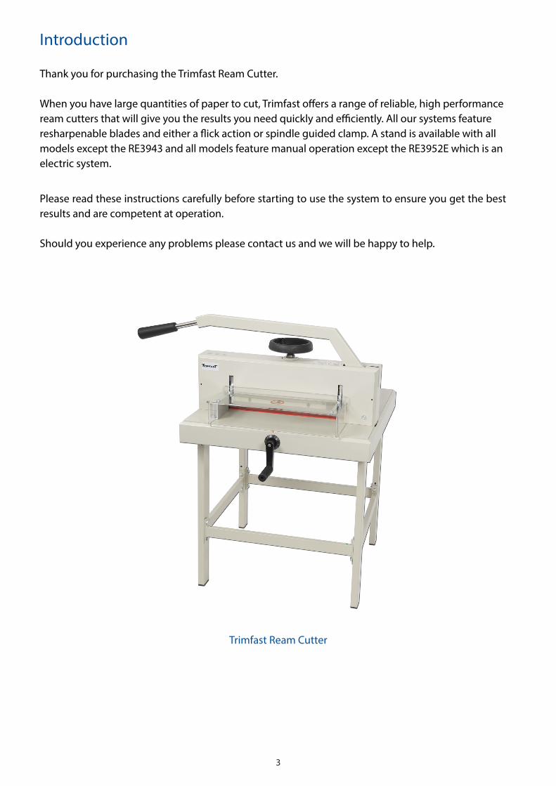
Trimfast Ream Cutter
3
Thank you for purchasing the Trimfast Ream Cutter.
When you have large quantities of paper to cut, Trimfast offers a range of reliable, high performance ream cutters that will give you the results you need quickly and efficiently. All our systems feature resharpenable blades and either a flick action or spindle guided clamp. A stand is available with all models except the RE3943 and all models feature manual operation except the RE3952E which is an electric system.
Please read these instructions carefully before starting to use the system to ensure you get the best results and are competent at operation.
Should you experience any problems please contact us and we will be happy to help.
Introduction
Trimfast Ream Cutter
4
• Please read these instructions carefully. Note the safe operational requirements, warnings andcautions. Use the product correctly and with care for the purpose for which it was intended. Failure to do so may cause damage or personal injury, and will invalidate the warranty.
• Please keep instructions safe for future use. • Keep this product out of the reach of children.• Ensure that no more than one person is working at the same system at the same time.• Keep hands away from the blade to avoid injury.• Keep loose items eg. jewellery, clothing, neckties etc away from the blade to avoid personal
injury or damage to the product.• Ensure lever is moved with both hands. • After use ensure the knife lever is moved back to the starting position until the knife is locked.• Do not disassemble the front safety guard.• Do not grasp underneath the knife edge.• Follow all instructions when replacing the knife blade. • This product is intended for indoor use only. Do not use outdoors.• Do not expose product to water or other liquids.• Keep guards and covers in place at all times. • Ensure you are stood in front of the system when in use. • Do not force the system.• Maintain system with care. • For electric models, ensure the power supply is disconnected when not in use.• This cutting system is designed for cutting paper, do not cut wood, plastic etc with the cutter.
Specifications
Safety Instructions
Model Length Max Paper Size Cutting Capacity Table Size
RE3943** 370mm A4 15mm/150 sheets 265x475x450mmRE3947 430mm A3 20mm/200 sheets 1060x640x700mmRE3946 430mm A3 60mm/600 sheets 1080x680x740mmRE3971 475mm A3 80mm/800 sheets 1310x766x769mm
RE3952Eo 430mm A3 45mm/450 sheets 1210x630x820mm
** Stand not included, available to order. o Electric model
5
General Maintenance
All moving parts need to be lubricated and oiled from time to time. Before lubricating these parts the system should be cleaned from dust, debris and any oil and grease.
All moving parts attached with screws need to be checked to ensure these are fastened securely. Some screws may loosen in transit. It is advised that all screws are re-checked and re-tightened after around 200 cuts. Maintaining the system correctly will help avoid faults and damage.
After unpacking the Trimfast Ream Cutter, check to make sure that there is no damage.
Contents
Spare Parts
For Spare Parts please contact your supplier
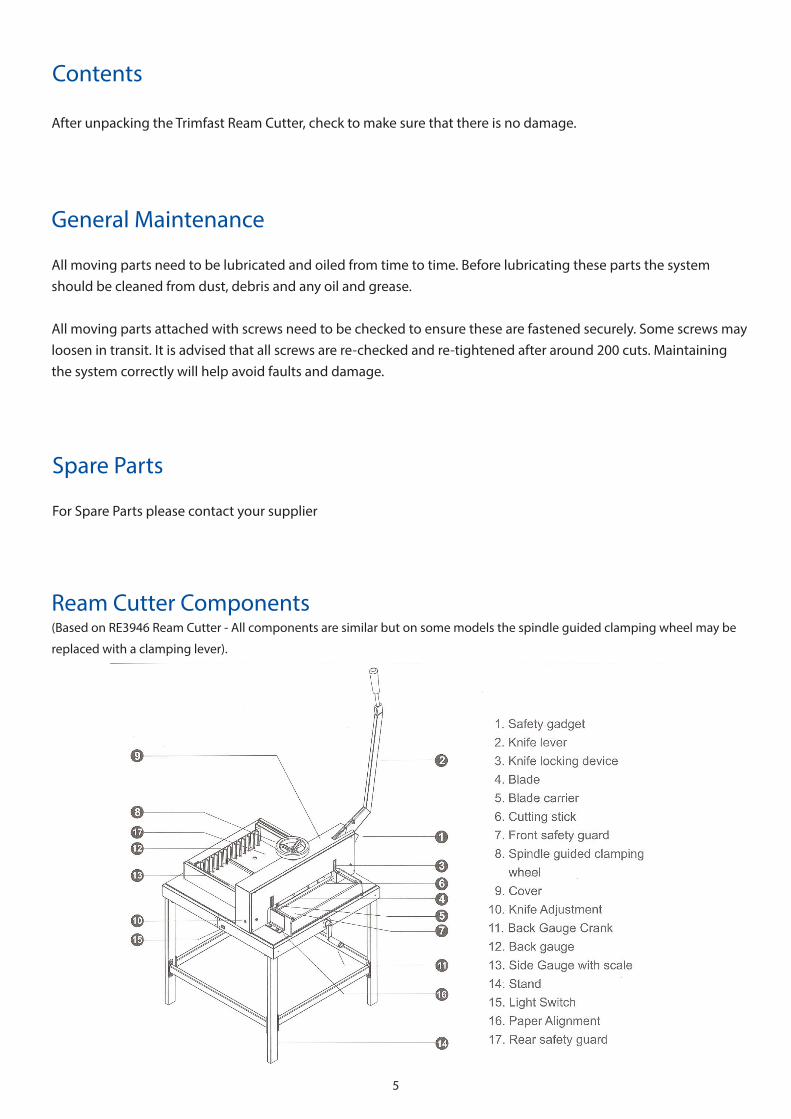
Ream Cutter Components(Based on RE3946 Ream Cutter - All components are similar but on some models the spindle guided clamping wheel may be
replaced with a clamping lever).
6
• SafetyGadget - This is to protect fingers whilst operating the cutter.• KnifeLever - The knife lever enables cutting without effort. A sharp knife is important for the
best performance. After each cutting operation the knife lever must be placed back into its top position until the knife lever is locked.
• KnifeLockingDevice- This secures the knife in its top, raised position. A cutting operationcan only be carried out when the front safety guard is in the down position and the locking device is released. Please note the knife locking device is controlled and connected with the front safety guard and the knife lever. You can open the front safety guard only when the knife lever is in its starting point.
• Blade - Made of high quality carbon steel, the blade is resharpenable. • BladeCarrier - Attached to the system are a number of screws. Only disassemble these for a
knife change or when carrying out maintenance on the system.• CuttingStick- Made from strong plastic. It can be used twice on each size.• FrontSafetyGuard - This must be lowered before each cutting operation, the locking device
can then be released. The front safety guard can be reopened only when the knife lever is placed in its top, raised position.
• SpindleGuidedClampingSystem - For pressing and holding the paper stack which is being cut.Turn the clamp wheel clockwise to clamp the paper stack. Turn the wheel anti-clockwise to release the paper stack.
• FlickActionClampingSystem - For pressing the paper pile which is being cut. Press leverforward to open the clamping system. Press lever backwards to close the clamping system.
• Cover - Attached to the machine with a number of screws. Only disassemble for a knife changeor when carrying out maintenance on the system.
• KnifeAdjustment - The knife can be adjusted slightly by using the adjustment screw, turnclockwise to adjust the knife downwards. Turn the screw anti-clockwise to adjust the knife upwards. Please note the maximum adjustment is 2mm. A knife that is adjusted too deeply does not only damage the cutting stick but the knife itself.
• BackGaugeCrank - The crank is indirectly connected to the back gauge. Connection is madeby a slight push of the crank towards the system. The connection is released when pulling the crank towards the operator. Turn clockwise: The back gauge moves towards the knife. Turn anti-clockwise: The back gauge moves away from the knife. The scale behind the crank is for fine adjustment of the back gauge.
• BackGauge - For adjusting to the desired cutting size and for exact positioning of the paperpile to be cut.
• SideGaugewithscale - In mm/cm and inches. The indicator on the back gauge crank showingthe measurement, which adjusts the scale of the side gauge. Fine adjustment is done via the mm scale of the scale ring.
• Stand- Made from heavy duty steel. • LightSwitch - This will shine a bright line to indicate where the cut will be made. This will
enable accurate cutting.• PaperAlignment - Made from steel to align the paper on the left hand side.• RearSafetyGuard- Made of acrylic to protect the safety of operation and prevent from dust.• SelectSwitch - Turn to the right to get ready for operation, turn left for blade change. (Electric models)
Ream Cutter Components & Descriptions(The below descriptions are based on the majority of the Ream Cutter systems, some models may differ and not include all
components).
7
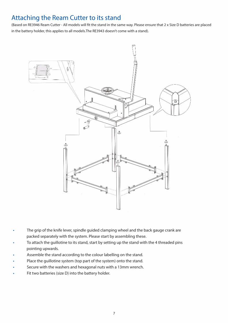
Attaching the Ream Cutter to its stand(Based on RE3946 Ream Cutter - All models will fit the stand in the same way. Please ensure that 2 x Size D batteries are placed
in the battery holder, this applies to all models.The RE3943 doesn’t come with a stand).
• The grip of the knife lever, spindle guided clamping wheel and the back gauge crank arepacked separately with the system. Please start by assembling these.
• To attach the guillotine to its stand, start by setting up the stand with the 4 threaded pinspointing upwards.
• Assemble the stand according to the colour labelling on the stand. • Place the guillotine system (top part of the system) onto the stand.• Secure with the washers and hexagonal nuts with a 13mm wrench.• Fit two batteries (size D) into the battery holder.

8
• Pushing the back gauge crank slightly towards the system and turn anti-clockwise in order to insert thepaper pile. Turn the back gauge crank clockwise to adjust the measure to what you need.
• Turn the clamp hand wheel clockwise to clamp the paper pile and close the safety guard. • Pushing two enable switches simultaneously and hold it until the cutting is complete.• The light will check the position of the paper pile to be cut.• The blade will automatically stop when the safety guard is open. The system can be operated only
when the safety guard is closed securely.
OperationElectricModelsOnly:
Electric Power Paper Trimming Specification
Installation of power systemPleasefollowthebelowspecificationwheninstallingthesystem:
• The knife does not move: please make sure the main motor magnetic contact is activated.• No power: Please check the power source and the fuse• Overloaded: Please wait until the breaker reset automatically when the indicator light is off, and then
reduce the pile of paper. • The system cannot work after closing the safety guard: Press the 2 enable switches again and check
the safety guard is completely closed.
Trouble Shooting
Pleasenote:Donotdisposeofelectricalappliancesasunsortedwaste,disposeofthissystemcorrectly.
9
• Place the knife lever in its top position.• Raise the front safety guard. Push the paper pile along the paper alignment from the front of the
system, and position against the back and left hand side gauges.• Push the back gauge crank towards the cutter to engage, turn the crank handle clockwise to
bring the back gauge towards the knife until the paper measurement is reached. With the help of the fine adjustment ring, accurate measurement can easily be reached.
• Release the back gauge crank, so that the unintentional movement of the back gauge can beprevented.
• Turn the spindle hand wheel clockwise to clamp the paper pile tight.• Lower the front safety guard, to reach the table.• Using both hands, lower the knife lever to cut the paper stack. When the cut is complete place the
lever into its top starting position, until this locks. • Turn the spindle hand wheel counter clockwise to release the paper pile. Lift the front safety guard,
and remove the paper pile from the cutter.
Ream Cutter Operation(Spindle hand wheel systems):
(Flick action clamping system): Follow the above step one and two
• Release the screw of the back gauge and adjust to the accurate measurement for cutting. Be sure totighten the screw once in its precise position.
• Switch the lever of the flick action clamping system backwards (near to operator) when the clampingdevice touches the paper pile, apply pressure to the handle until the paper pile is secured.
• Close the hand guard firmly onto the table then the safety lock is released. • Using both hands, lower the knife lever to cut the paper stack. When the cut is complete place the
lever into its top starting position, until this locks. • Release the hand lever of the flick action clamping system. Lift the hand guard, and remove the paper
pile from the cutter.
Cutting StickIf the last sheet of the paper pile does not cut through, even though the knife adjustment has already been adjusted, the cutting stick should be changed or rotated. The cutting stick can be used twice on each side, which means you can rotate each stick 8 times. The cutting stick fits into the system table and can be lifted out using a screw driver. The pins in the base of the systems table hold the cutting sticks, by securing the holes on each end of the stick onto the pins.
Please note. When the cutting stick is changed, the knife has to be readjusted. A knife which cuts too deeply damages not only the cutting stick but also the knife too.
10
Blade ResharpeningPlease note: A dull knife does not cut accurately. The cutting of thicker stock paper or cardboard, will blunt the blade easily. When the knife cannot cut the paper pile cleanly even when the cutting stick has been changed and the knife adjustment has been done, then the blade is required to be resharpened. When you need to resharpen the blade, take the blade to be resharpened and then refer to the ‘Blade Replacement’ section for instructions on how to reload the blade. Precise cuts are only possible with a sharp knife. The knife should be changed as soon as the quality and the accuracy of the cuts are not to the expected standards. If the knife should jam in the paper pile or leave grooves in the paper, the knife must be changed right away. Knife life with basic paper is approximately 600 cutting times, depending on the cutting capacity. This will vary depending on the paper stock being cut. The knife should only be changed by a single person, to avoid injuries. The cutting edge is extremely sharp and must be handled with care.
NOTE:Pleaserefertothefollowingsectionsofthemanualfor‘BladeReplacement’
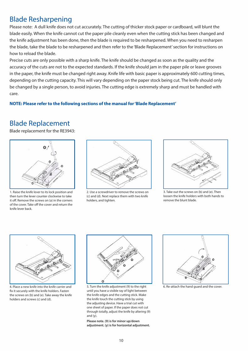
Blade ReplacementBlade replacement for the RE3943:
5. Turn the knife adjustment (9) to the right until you have a visible ray of light between the knife edges and the cutting stick. Make the knife touch the cutting stick by using the adjusting device. Have a trial cut with one sheet of paper. If the paper does not cut through totally, adjust the knife by altering (9) and (y).
Please note. (9) is for minor up/down adjustment. (y) is for horizontal adjustment.
6. Re-attach the hand guard and the cover.
1. Raise the knife lever to its lock position and then turn the lever counter clockwise to take it off. Remove the screws on (a) in the corners of the cover. Take off the cover and return the knife lever back.
2. Use a screwdriver to remove the screws on (c) and (d). Next replace them with two knife holders, and tighten.
4. Place a new knife into the knife carrier and fix it securely with the knife holders. Fasten the screws on (b) and (e). Take away the knife holders and screws (c) and (d).
3. Take out the screws on (b) and (e). Then loosen the knife holders with both hands to remove the blunt blade.
11
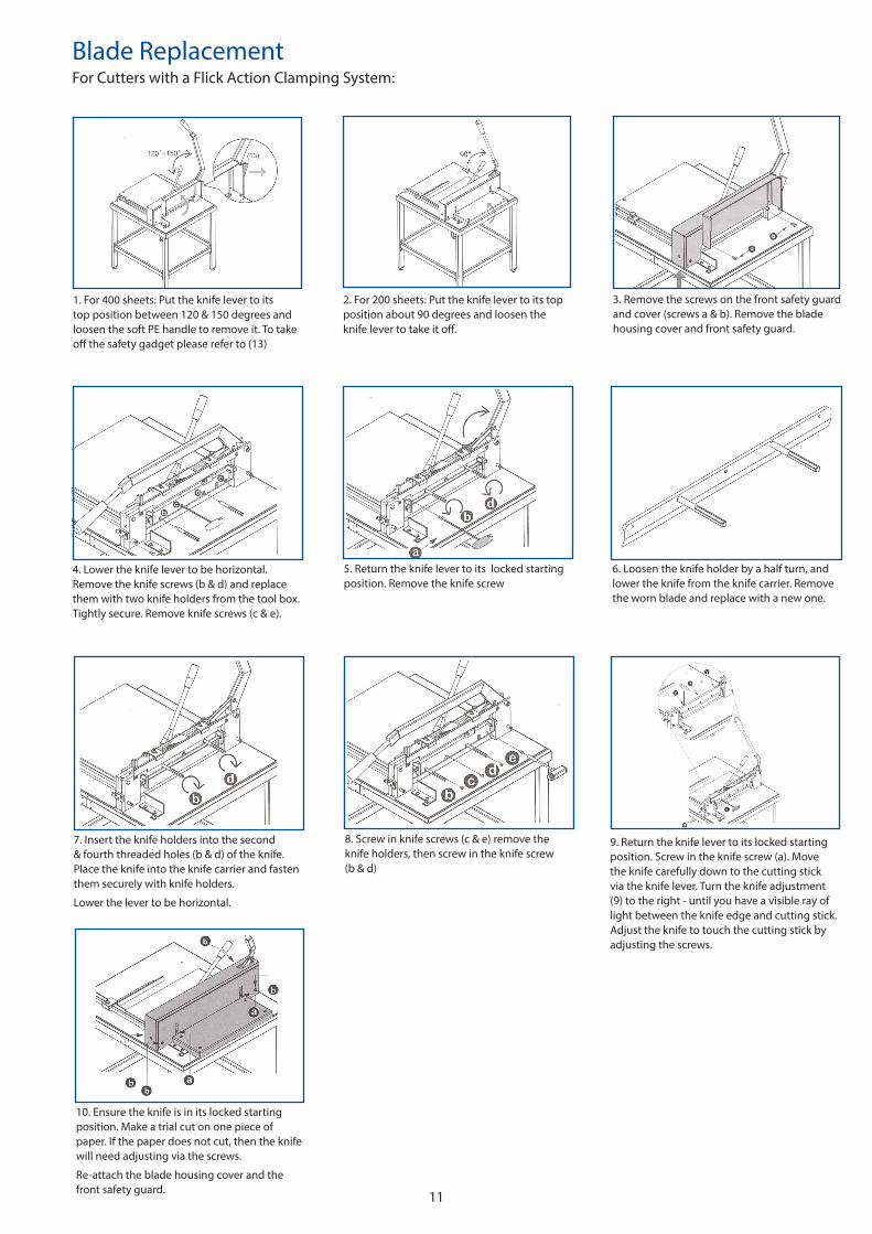
Blade ReplacementFor Cutters with a Flick Action Clamping System:
5. Return the knife lever to its locked starting position. Remove the knife screw
6. Loosen the knife holder by a half turn, and lower the knife from the knife carrier. Remove the worn blade and replace with a new one.
1. For 400 sheets: Put the knife lever to its top position between 120 & 150 degrees and loosen the soft PE handle to remove it. To take off the safety gadget please refer to (13)
2. For 200 sheets: Put the knife lever to its top position about 90 degrees and loosen the knife lever to take it off.
4. Lower the knife lever to be horizontal. Remove the knife screws (b & d) and replace them with two knife holders from the tool box. Tightly secure. Remove knife screws (c & e).
3. Remove the screws on the front safety guard and cover (screws a & b). Remove the blade housing cover and front safety guard.
8. Screw in knife screws (c & e) remove the knife holders, then screw in the knife screw (b & d)
7. Insert the knife holders into the second & fourth threaded holes (b & d) of the knife. Place the knife into the knife carrier and fasten them securely with knife holders.
Lower the lever to be horizontal.
10. Ensure the knife is in its locked starting position. Make a trial cut on one piece of paper. If the paper does not cut, then the knife will need adjusting via the screws.
Re-attach the blade housing cover and the front safety guard.
9. Return the knife lever to its locked starting position. Screw in the knife screw (a). Move the knife carefully down to the cutting stick via the knife lever. Turn the knife adjustment (9) to the right - until you have a visible ray of light between the knife edge and cutting stick. Adjust the knife to touch the cutting stick by adjusting the screws.
12
Blade ReplacementFor Cutters with a Spindle Hand Wheel:
5. Remove the knife holders and the old blade, replace this with a new blade. Screw the knife holders back into place. Insert the knife holders into the opened second & fourth hole of the blade carrier and fasten.
6. Lower the knife lever until this is horizontal, tighten the knife screws (c & e) remove the knife holders, then fasten the knife screws (b & d).
1. Remove the safety gadget (1). Raise the knife lever. Remove the screw (c) on the clamp wheel. Remove all the screws fixed on the cover. Place the knife lever at 75 degrees and remove the knife cover.
2. Lower the knife lever until this is horizontal.
4. Return the knife lever to its locked starting position. Remove the knife screw (a). Loosen the knife holders (by only half turn) and lower the blade downwards from the blade carrier and remove the blade carefully.
3. Remove the screws (b & d), replace them with the two knife holders from the tool box and tighten them securely. Remove the knife screws (c & e).
7. Return the knife lever to its locked starting position. Screw in the knife screw (a). Move the knife carefully down to the cutting stick via the knife lever. Turn the knife adjustment (8) to the right - until you have a visible ray of light between knife edge and cutting stick. Adjust the knife to touch the cutting stick by adjusting the screws. Move the knife lever to its locked raised position. Make a trial cut with one sheet of paper, if the paper does not cut through totally, then the knife needs adjustingusing the screws (y & 8).
Please note. (8) is for minor up/down adjustment. (y) is for horizontal adjustment.
8. Place the knife lever at 75 degrees and assemble the cover. Tighten all screws on the cover. Assemble the spindle clamp hand wheel and screw (c) to fix tightly. Assemble the safety gadget.
13
Blade ReplacementFor Electric Ream Cutters:
5. Close the safety guard, turn the select switch to the right. Press the 2 enable switches together, then the cutter will move upwards. Turn the select switch to the middle and turn off the power switch. Open the safety guard and remove the left screw.
6. Remove the 2 other screws (B) but keep the central one (A) as it is.
1. Remove the screws at both ends of the cover.
2. Remove the clamp hand wheel and put it aside then remove the cover.
4. Press 2 enable switches simultaneously, then the cutter will move down to the end. Turn the select switch to the middle, open the safety guard and remove the right screw on the cutter.
3. Press the power switch on, and turn the select switch to the left.
7. Screw the 2 cutter holders (in tool box) into B position tightly to avoid the blade falling down then remove the central screw A.
8. Grip and loosen the cutter holders by just a turn, move the cutter downwards and take away the cutter carefully.
9. Turn the 3 (socket headless) adjustable screws by T-wrench anti-clockwise, from cutter support as high as possible (1mm up at least) and turn the blade fine adjustment device on the right hand side clockwise.

14
14. If the blade and cutting stick does not match, adjust the 3 (socket headless) screws until they are 100% matching together.
15. Turn the select switch to the right and press the 2 enable switches together to raise the cutter and check the cutting function with one sheet of paper. If the cutter does not cut accurately, please follow the following steps.
10. Remove the protective pad and hold it securely by the 2 cutter holders then reverse the procedure to replace the new blade.
11. Assemble and turn the clamp hand wheel downwards. The blade and the blade holder should be close together.
13. Replace the left screw and close the safety guard. Turn the power switch on and turn the select switch to the left then press the 2 enable switches together. The cutter will lower. Turn the select switch to the middle, open the safety guard and fasten the right screw on the right end of the blade holder.
12. Fasten the screw A tightly then remove the 2 cutter holders and fasten the 2 B screws tightly.
16. Using a 3mm hexagon wrench to adjust the 3 (socket headless) screws on the top of the carrier slightly and turn the fine adjustment device of the cutter upwards/downwards until the blade is in contact with the cutting stick. Optimal adjustment is done when the last sheet is cut accurately.
17. Place the metal cover onto the cutter carrier then replace the clamp hand wheel and fasten the screws. Finally fasten the screws on the two ends of the metal cover.

15
Warranty & Incorrect UseIMPORTANT INFORMATION
Your Trimfast Finishing System should reach you in perfect condition, however please retain all of the original packaging once you have unpacked your Finishing System in case you need to return it for repair. If your system arrives damaged or faulty in anyway, this must be reported to your supplier immediately. If the Finishing System is sent back for repair under warranty and is damaged in transit due to faulty packaging your warranty may be void.
Your Finishing System is guaranteed for 1 year from date of purchase covering defective parts and general wear and tear; it does not cover any damage to the blades.
E&O.E