product line instructions deburr z - tapmatic
TRANSCRIPT

1
……................by
Safety and Operation Instructions DeBurr-Z
TAPMATIC ⚫ 802 Clearwater Loop, Post Falls ID 83854 Tel. 800 854-6019 ⚫ Tel. 001 208 773-2951 ⚫ Fax 001 208 773-3021
[email protected] ⚫ www.tapmatic.com
CNC Floating Deburring Tool Deburr It While you Make It!

2
WARNING: To Avoid Serious Injury And Ensure Best Results for Your Application, Please Read Care-fully All Operator and Safety Instructions provided for your DeBurr-Z, as well as all other safety instructions that are applicable, especially those for your machine tool. 1.Proper Clothing: the rotating spindle of a machine tool can snag loose fitting clothing, jewelry or long hair. Never wear jewelry, long sleeves, neckties, gloves or anything else that could become caught when operating a machine tool. Long hair must be restrained or netted to prevent it from becoming entangled in rotating spindle. 2.Proper Eye Protection: Always wear safety glasses with side shields to protect your eyes from flying particles.
3.Proper Work Piece Fixturing: Never hold the work piece or the vise it is held in, by hand. The work piece must be clamped firmly to the table of the machine so that it cannot move, rotate or lift.
4.Always Be Aware Of The Potential Hazards Of A Machining Operation: sometimes working with your ma-chine can seem routine. You may find that you are no longer concentrating on the operation. A feeling of false se-curity can lead to serious injury. Always be alert to the dangers of the machines with which you work. Always keep hands, body parts, clothing, jewelry and hair out of the areas of operation, when the machine spindle is moving. Areas of operation include the immediate point of machining and all transmission components including the debur-ring tool. Never bring your hand, other body parts or anything attached to your body into any of these areas until the machine spindle is completely stopped. 5.Be aware of any other applicable safety instructions / requirements
_____________________________________________________________________________ CHECK LIST FOR GOOD DEBURRING.
1. Never use this deburring tool before reading all safety instructions for this tool, as well as the machine it is to be used on.
2. Is the tool correctly inserted into the holder/collet and secured? 3. Is the force setting adjusted correctly? See instructions. 4. Is machine feed correct? 5. Has the tool length been correctly defined? 6. Is work piece held rigidly against rotation and upward movement? 7. Have possible collision areas been checked and eliminated?
TAPMATIC ⚫ 802 Clearwater Loop, Post Falls ID 83854 Tel. 800 854-6019 ⚫ Tel. 001 208 773-2951 ⚫ Fax 001 208 773-3021
[email protected] ⚫ www.tapmatic.com
……................by
Safety and Operation Instructions for the DeBurr-Z

3
……................by
Safety and Operation Instructions for the DeBurr-Z
TAPMATIC ⚫ 802 Clearwater Loop, Post Falls ID 83854 Tel. 800 854-6019 ⚫ Tel. 001 208 773-2951 ⚫ Fax 001 208 773-3021
[email protected] ⚫ www.tapmatic.com
All-in One Overview Advantages, Function and Characteristics The DeBurr-Z deburring tool is an axially (Z axis) floating tool holder, for use on CNC machines, designed for deburring or chamfering the sharp edges of a work piece. The floating holder allows the burr cutting tool to follow the edges of the part even when these are not clearly defined or vary in posi-tion like in the case of castings, cross holes or intersecting surfaces. The DeBurr-Z compensates in both the compression and the extension direction allowing you to deburr both the top edges and underside edges of the work piece. There are 10mm of both compression float and extension float and the force exerted against the work piece edge can be ad-justed for harder work piece materials or to increase the size of the edge break. The force adjustment works equally and simultaneously in both the compression and extension direction and making an adjustment does not effect the tool length. Neighboring tools and collision areas in the machine’s tool magazine will normally not pose a problem thanks to the com-pact design. Maximum recommended speed is 10,000 RPM. The feed rate can be programmed based on the material, and the desired edge break size and finish. Using external flood coolant / lubrication, results in the longest tool life and best finish. Burr cutting tools with angular and spherical profiles can be used, like the examples shown here.

4
……................by
Safety and Operation Instructions for DeBurr-Z
TAPMATIC ⚫ 802 Clearwater Loop, Post Falls ID 83854 Tel. 800 854-6019 ⚫ Tel. 001 208 773-2951 ⚫ Fax 001 208 773-3021
[email protected] ⚫ www.tapmatic.com
Burr Cutting Tool Recommendations Burrs made from High Speed Steel, or Carbide, with angular or spherical profiles are recommended. A variety of tooth patterns are available from different manufacturers. The tooth pattern influences the finish, and metal removal rate and some patterns may be designed to work best in certain types of materials.
For spherical profiles, to allow axial floating, please avoid using the side of the burr cutting tool.
Please note that the DeBurr-Z floats only in compres-sion and extension. It does not com-pensate in the radi-al or angular direc-tions. We recom-mend a 90° includ-ed angle for producing a 45°chamfer.
Avoid using side of tool
55°
55°
Please note that the DeBurr-Z floats only in compression and extension. It is not able to climb very abrupt, or steep contours.
Programming a Z axis movement is needed when climbing steeper incline surfaces
Please use caution to avoid contacting the work piece with the edge or side of the cutting tool.
Select a Burr Cutting tool with an included angle that avoids side contact.
5
……................by
Safety and Operation Instructions for DeBurr-Z
TAPMATIC ⚫ 802 Clearwater Loop, Post Falls ID 83854 Tel. 800 854-6019 ⚫ Tel. 001 208 773-2951 ⚫ Fax 001 208 773-3021
[email protected] ⚫ www.tapmatic.com
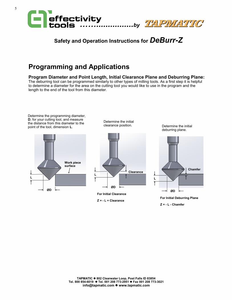
Determine the programming diameter, D, for your cutting tool, and measure the distance from this diameter to the point of the tool, dimension L.
L
ØD
Programming and Applications
Program Diameter and Point Length, Initial Clearance Plane and Deburring Plane: The deburring tool can be programmed similarly to other types of milling tools. As a first step it is helpful to determine a diameter for the area on the cutting tool you would like to use in the program and the length to the end of the tool from this diameter.
L
ØD
Clearance
L
ØD
Chamfer
For Initial Clearance Z = - L + Clearance
For Initial Deburring Plane Z = - L - Chamfer
Work piece surface
Determine the initial clearance position. Determine the initial
deburring plane.

6
Please note when programming a part for top edge deburring, it is best to begin cutting at the lowest point.
……................by
Safety and Operation Instructions for DeBurr-Z
TAPMATIC ⚫ 802 Clearwater Loop, Post Falls ID 83854 Tel. 800 854-6019 ⚫ Tel. 001 208 773-2951 ⚫ Fax 001 208 773-3021
[email protected] ⚫ www.tapmatic.com
3mm
Ø6mm
Please note the total amount of compression float is 10mm. If there is a large amount of height variation it will be nec-essary to program the Z axis of the machine to approximately follow the contour of the part in order to keep within the 10mm compression limit.
3mm
Ø6mm
1mm
3mm
Ø6mm
0.5mm
Z0
Example Top Edge Deburring: The work piece surface = Z0 D = 6 mm L = 3 mm Clearance = 1 mm Program Chamfer Depth = 0.5 mm
Initial Clearance Z = - L + Clearance Z = -3 + 1 Z = Z-2.
Determine the initial clearance position. Determine the initial
deburring plane.
Initial Deburring Plane Z = - L - Chamfer Z = -3 - 0.5 Z = Z-3.5

7
Please note when programming a part for underside edge deburring, it is best to program and begin cutting at the highest position.
……................by
TAPMATIC ⚫ 802 Clearwater Loop, Post Falls ID 83854 Tel. 800 854-6019 ⚫ Tel. 001 208 773-2951 ⚫ Fax 001 208 773-3021
[email protected] ⚫ www.tapmatic.com
7mm
Ø8mm
Please note the total amount of extension float is 10mm. If there is a large amount of height variation it will be nec-essary to program the Z axis of the machine to approximately follow the contour of the part in order to keep within the 10mm extension limit.
6mm
Z0
Initial Clearance Position Z = - Thickness - Clearance - L Z = -6 - 1 - 7 Z = Z-14
Initial Deburring Plane Z = - Thickness + Chamfer - L Z = -6 + 0.5 - 7 Z = Z-12.5
7mm
Ø8mm
6mm
Example Underside Edge Deburring: The work piece surface = Z0 D = 8 mm L = 7 mm Part thickness = 6mm Clearance = 1 mm Program Chamfer Depth = 0.5 mm
Z0
1mm
Safety and Operation Instructions for DeBurr-Z
7mm
Ø8mm
6mm
Z0
0.5mm

8
……................by
TAPMATIC ⚫ 802 Clearwater Loop, Post Falls ID 83854 Tel. 800 854-6019 ⚫ Tel. 001 208 773-2951 ⚫ Fax 001 208 773-3021
[email protected] ⚫ www.tapmatic.com
Adjusting the Force: The spring force for both compression and extension can be adjusted simultaneously and equal-ly by turning the sleeve. There is a scale for reference with setting 0 being the lightest force and setting 6 the highest.
Floating over surfaces with height variation: When floating over edges that vary in height , using lower force settings will result in the most consistent edge break.
Setting 0
Setting 6
Factors that influence the size of the edge break:
• Increasing the force setting will increase the edge break
• Increasing the compression or extension distance into the work piece will increase the edge break.
• Reducing the feed rate will increase the size of the edge break.
Factors that influence the finish:
• Higher Spindle Speed improves the finish.
• Slower feed rates will improve the finish.
• Taking a second pass around the part can also improve the finish.
• The tooth pattern of the cutting tool can also influence the finish. A finer tooth pattern can improve the finish but some materials like aluminum may cause the cutting tool to load up with material if the tooth pattern is too fine.
• Using coolant lubrication will improve the finish and cutting tool life.
Safety and Operation Instructions for DeBurr-Z
+

9
……................by
TAPMATIC ⚫ 802 Clearwater Loop, Post Falls ID 83854 Tel. 800 854-6019 ⚫ Tel. 001 208 773-2951 ⚫ Fax 001 208 773-3021
[email protected] ⚫ www.tapmatic.com
Entering and exiting from the part: When the deburring tool enters or exits the work piece to begin cutting, there can be a larger edge break at these locations. This can be minimized in several ways.
For top edge deburring enter and exit at the lowest point.
For underside edge deburring enter and exit at the highest point.
Always approach the part in a Z axis plane. If you move the cutter sideways into the part in the X,Y axis plane, it will cut more material as it climbs onto the edge.
Z
X or Y
Select the best area to enter and exit the part when possible.
Safety and Operation Instructions for DeBurr-Z
Z
Correct
Incorrect

10
……................by
TAPMATIC ⚫ 802 Clearwater Loop, Post Falls ID 83854 Tel. 800 854-6019 ⚫ Tel. 001 208 773-2951 ⚫ Fax 001 208 773-3021
[email protected] ⚫ www.tapmatic.com
Entering and exiting from the part: When the deburring tool enters or exits the work piece to begin cutting, there can be a larger edge break at these locations. This can be minimized in several ways.
Use rapid approach or a fast feed rate to enter or exit the cut from your clearance plane. This minimizes the cycle time and also the size of the edge break at this location.
Z
G0 or G1 F10000. Using a fast feed rate may be better than rapid depending on the reaction time of the machine. Feed rate suggestion shown in mm (10,000mm/min = 400 in/min) We recommend using G64, to eliminate ex-act stop, to improve the machine’s reaction time between approach, cutting and exiting movements.
Z
Another option is to use a fast feed rate to ramp into the part from the clearance plane. This also helps to minimize the entry point. Similarly ramping out of the part from the cut-ting plane to the clearance plane helps to minimize the edge break at the exit point.
Making a finishing pass is one more way to reduce the appearance of a heavier edge break at entry and exit points.
Safety and Operation Instructions for DeBurr-Z
Ramping into part Ramping out of part
Approach
Exit
Can we help with an application? Please contact us at [email protected], or call us at 800 854-6019 or 001 208 773-2951

11
……................by
®
Installing the Cutting Tool:
TAPMATIC ⚫ 802 Clearwater Loop, Post Falls ID 83854 Tel. 800 854-6019 ⚫ Tel. 001 208 773-2951 ⚫ Fax 001 208 773-3021
[email protected] ⚫ www.tapmatic.com
Ident No. Description Part No.
1 Shank Cap 52219
2 O-Ring 2-014 70054
3 Screw 71162
4 Driver 522051
5 Key 74293
6 Spindle Ring 52224
7 1” Shank Housing 52210
7 20mm Shank Housing 522104
7 25mm Shank Housing 522103
8 Adjustment Traveler Left Hand 52203L
9 Adjustment Traveler Right Hand 52203R
10 Spring Washer (2 pcs) 52247
11 Spring (2 pcs) 52212
12 Threaded Sleeve 52207
13 O-Ring OR1002600 (3 pcs) 73654
14 Adjustment Sleeve Left Hand 52234L
15 Adjustment Sleeve Right Hand 52234
16 Nose Cone with Bushing 52236
17 O-Ring OR1501200 64359
18 Ident Sleeve 52206
19 O-Ring 30 x 2 52249
20 ER 11 Spindle 522351
21 M6 Adjustment Stop 52283
22 ER 11 Mini Nut 69318M
Keys, (Not Shown) ER11 Wrench 69317M 7/16” by 9/32” Wrench 28002 2mm Hex Key 27222 3mm Hex Key 27223 Please order collets and burr cutting tools separately.
Parts List
Safety and Operation Instructions for DeBurr-Z
Incorrect Correct
Always install the collet into the nut first. Make sure lip inside the nut goes into the collets groove.
Then thread the nut on to the holder.
Then slide in the cutting tool and tighten the nut with the wrenches.
Adjust M6 screw with 3mm hex key as a stop for the cutting tool.

12
……................by
TAPMATIC ⚫ 802 Clearwater Loop, Post Falls ID 83854 Tel. 800 854-6019 ⚫ Tel. 001 208 773-2951 ⚫ Fax 001 208 773-3021
[email protected] ⚫ www.tapmatic.com
Repair Service is available at…. Attention: Repair Department Tapmatic Corporation 802 Clearwater Loop Post Falls, ID 83854 Or through your local distributor.
To Expedite Repair: Return tool direct to Tapmatic Corporation. Tapmatic will inspect the tool and advise you of the repair costs by Fax or E-mail before the repair is completed. Cost Notification: Tapmatic will FAX or E-mail a cost notification to you, so-liciting your approval before repairs are completed. If it is determined that a tool cannot be repaired, at the customer’s request, Tapmatic will return the disassembled parts. We are not able to reassemble a tool using damaged or worn out parts. Optional Return Procedure: Tools may also be returned for repair through your local Tapmatic Distributor. They will ship the tool to us and include in-structions for the repair and return. You may already have an open account with them which facilitates the handling of invoicing. Priority Service: Tapmatic services tools returned for repair in the order in which they are received. All tools will be evaluated and repaired within three weeks from the date they arrive subject to receiving the customer’s approval to proceed with the repair. Priority is given to tools shipped to us by overnight or second day. If a repair is sent to us by UPS ground or similar service it can also be given priority. Just call and let us know you need priority service and advise if you would like the tool returned to you by overnight or second day. In the interest of fairness, to all our customers, we ask that you approve shipment by over-night or second day before we agree to upgrade your repair order to priority service. Typical turn around, not including shipping time, for priority repairs is 3 days subject to receiving the customer’s approval to proceed with the re-pair. If we can answer any questions please call our toll free number: 800 395-8231
0321/ DEBURR-Z / /
Safety and Operation Instructions for DeBurr-Z