product manual disc-o-flex coupling type...astm a-106, astm a-105 astm a-106, astm a-105 astm a-105...
TRANSCRIPT
R-PM-D-01/02-01/14 Page 1
RATHI TRANSPOWER PVT. LTD. PUNE - INDIA
PRODUCT MANUAL
DISC-O-FLEX COUPLING
TYPE – LM, EM, LMC, LMK, FLM, FEM, LMH & EMH

R-PM-D-01/02-01/14 Page 2
INDEX
CONTENTS PAGE
• Standard Features 3
• At a Glance 4
• Disc-o-flex Family 5
• Std. Material of Construction 6
• The Disc-pack - Heart of the Coupling 7-9
• Torque Transmission 9
• Flexibility 10
• Ratings for Standard Couplings 10
• Min. DBSE of LM,LMH & LMC Couplings 12
• Min. DBSE of EM,EMH Couplings 12
• Non-spacer couplings - Type LMK 13
• Couplings with Taper Bushes - Type LMT 14
• Couplings with Taper Bushes - Type EMT 15
• Requirements of API-671 & API-610 16
• Std. Tolerances for Finish Bore & Keyway 17
• Selection Procedure 18
• Applications 19
• Weight & M.I. for Disc-O-Flex Couplings 20-21
• Disc-O-Flex Couplings equivalent to Competitor’s Couplings 22-28

R-PM-D-01/02-01/14 Page 3
DISC-O-FLEX COUPLING
STANDARD FEATURES
• Zero maintenance
• High power to weight ratio: All metallic couplings in steel having high torque carrying capacity with light weight.
• No wearing parts
• No lubrication
• Zero backlash: Manufactured with precise tolerances to accommodate zero backlash which is required for the applications where lost motion is not acceptable such as servo or stepper driven positioning systems, custom designs for high torque applications & where dynamic balancing to accurate grades is required.
• Inherently balanced: As these couplings are machined symmetrically with the axis of rotation & all are in steel construction, there is no possibility of casting defects like porosity, blow holes. Hence the coupling is inherently balanced.
• Dynamically balanced to any precise grade of balancing as per ISO-1940.
• Easy installation with drop out spacer: Replacement of flexible element is possible without disturbing either of the equipments.
• Can be visually inspected without disturbing the assembly.
• All the non-stainless steel parts are coated with anti-corrosive agent.
• Antifly spacers: Available in construction with antifly spacers. Unlikely breakage of flexible elements will not allow the spacer to fly off the assembly.
• Non-standard material, length thru’ bore, hub dia., spacer lengths are also available on request.
• Available with std. SAE flanges for the application like diesel engine flywheels.
• Available with floating shafts for the applications like cooling tower fans.
• Available with single blade pack: used where parallel misalignment is zero.
• Available in non-sparking constructions: Used where the electrically insulated couplings are required.
R-PM-D-01/02-01/14 Page 4
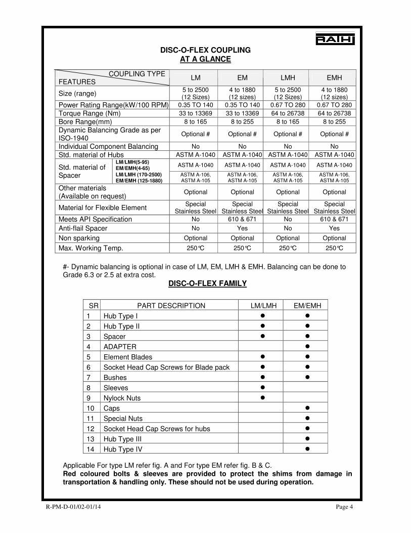
COUPLING TYPE FEATURES
LM EM LMH EMH
Size (range) 5 to 2500 (12 Sizes)
4 to 1880 (12 sizes)
5 to 2500 (12 Sizes)
4 to 1880 (12 sizes)
Power Rating Range(kW/100 RPM) 0.35 TO 140 0.35 TO 140 0.67 TO 280 0.67 TO 280
Torque Range (Nm) 33 to 13369 33 to 13369 64 to 26738 64 to 26738
Bore Range(mm) 8 to 165 8 to 255 8 to 165 8 to 255
Dynamic Balancing Grade as per ISO-1940
Optional # Optional # Optional # Optional #
Individual Component Balancing No No No No
Std. material of Hubs ASTM A-1040 ASTM A-1040 ASTM A-1040 ASTM A-1040 LM/LMH(5-95)
EM/EMH(4-65) ASTM A-1040 ASTM A-1040 ASTM A-1040 ASTM A-1040 Std. material of
Spacer LM/LMH (170-2500) EM/EMH (125-1880)
ASTM A-106, ASTM A-105
ASTM A-106, ASTM A-105
ASTM A-106, ASTM A-105
ASTM A-106, ASTM A-105
Other materials (Available on request)
Optional Optional Optional Optional
Material for Flexible Element Special
Stainless Steel Special
Stainless SteelSpecial
Stainless SteelSpecial
Stainless Steel
Meets API Specification No 610 & 671 No 610 & 671
Anti-flail Spacer No Yes No Yes
Non sparking Optional Optional Optional Optional
Max. Working Temp. 250°C 250°C 250°C 250°C
DISC-O-FLEX COUPLING AT A GLANCE
#- Dynamic balancing is optional in case of LM, EM, LMH & EMH. Balancing can be done to Grade 6.3 or 2.5 at extra cost.
DISC-O-FLEX FAMILY
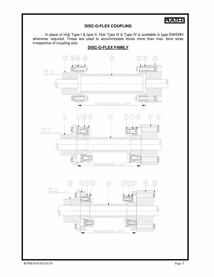
Applicable For type LM refer fig. A and For type EM refer fig. B & C. Red coloured bolts & sleeves are provided to protect the shims from damage in transportation & handling only. These should not be used during operation.
SR PART DESCRIPTION LM/LMH EM/EMH
1 Hub Type I � �
2 Hub Type II � �
3 Spacer � �
4 ADAPTER �
5 Element Blades � �
6 Socket Head Cap Screws for Blade pack � �
7 Bushes � �
8 Sleeves �
9 Nylock Nuts �
10 Caps �
11 Special Nuts �
12 Socket Head Cap Screws for hubs �
13 Hub Type III �
14 Hub Type IV �
R-PM-D-01/02-01/14 Page 5
DISC-O-FLEX COUPLING In place of Hub Type I & type II, Hub Type III & Type IV is available in type EM/EMH whenever required. These are used to accommodate bores more than max. bore sizes irrespective of coupling size.
DISC-O-FLEX FAMILY
R-PM-D-01/02-01/14 Page 6
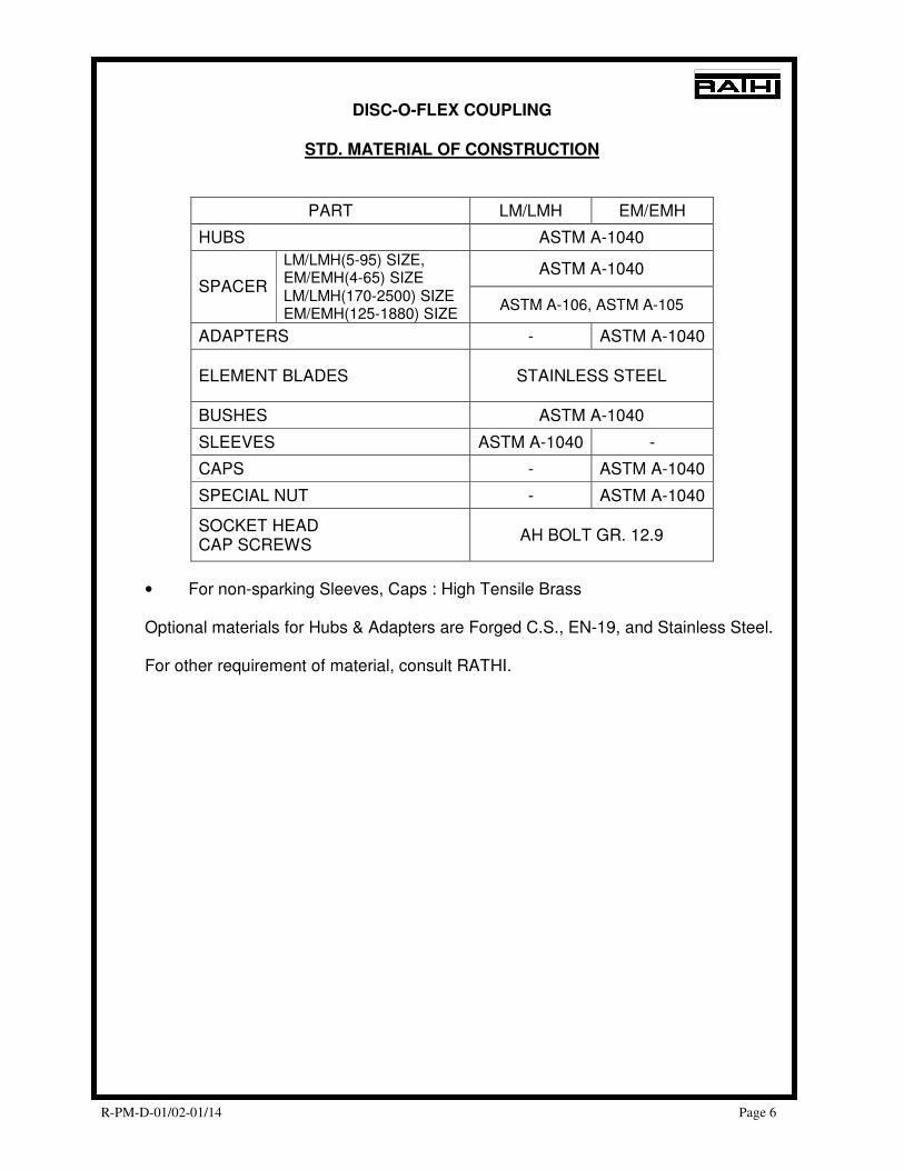
DISC-O-FLEX COUPLING
STD. MATERIAL OF CONSTRUCTION
PART LM/LMH EM/EMH
HUBS ASTM A-1040
LM/LMH(5-95) SIZE, EM/EMH(4-65) SIZE
ASTM A-1040 SPACER
LM/LMH(170-2500) SIZE EM/EMH(125-1880) SIZE
ASTM A-106, ASTM A-105
ADAPTERS - ASTM A-1040
ELEMENT BLADES STAINLESS STEEL
BUSHES ASTM A-1040
SLEEVES ASTM A-1040 -
CAPS - ASTM A-1040
SPECIAL NUT - ASTM A-1040
SOCKET HEAD CAP SCREWS
AH BOLT GR. 12.9
• For non-sparking Sleeves, Caps : High Tensile Brass Optional materials for Hubs & Adapters are Forged C.S., EN-19, and Stainless Steel. For other requirement of material, consult RATHI.
R-PM-D-01/02-01/14 Page 7
DISC-O-FLEX COUPLING
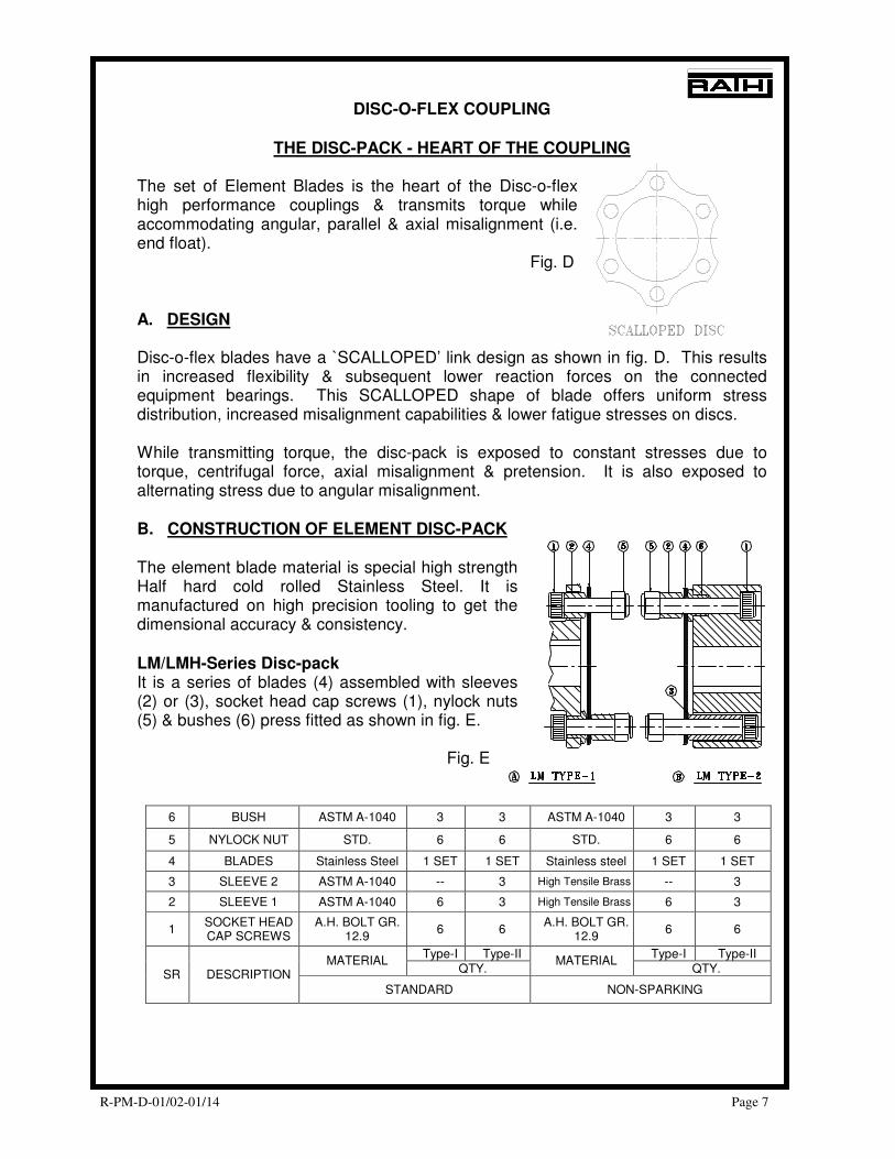
THE DISC-PACK - HEART OF THE COUPLING
The set of Element Blades is the heart of the Disc-o-flex high performance couplings & transmits torque while accommodating angular, parallel & axial misalignment (i.e. end float). Fig. D A. DESIGN Disc-o-flex blades have a `SCALLOPED’ link design as shown in fig. D. This results in increased flexibility & subsequent lower reaction forces on the connected equipment bearings. This SCALLOPED shape of blade offers uniform stress distribution, increased misalignment capabilities & lower fatigue stresses on discs. While transmitting torque, the disc-pack is exposed to constant stresses due to torque, centrifugal force, axial misalignment & pretension. It is also exposed to alternating stress due to angular misalignment. B. CONSTRUCTION OF ELEMENT DISC-PACK The element blade material is special high strength Half hard cold rolled Stainless Steel. It is manufactured on high precision tooling to get the dimensional accuracy & consistency. LM/LMH-Series Disc-pack It is a series of blades (4) assembled with sleeves (2) or (3), socket head cap screws (1), nylock nuts (5) & bushes (6) press fitted as shown in fig. E.
Fig. E
6 BUSH ASTM A-1040 3 3 ASTM A-1040 3 3
5 NYLOCK NUT STD. 6 6 STD. 6 6
4 BLADES Stainless Steel 1 SET 1 SET Stainless steel 1 SET 1 SET
3 SLEEVE 2 ASTM A-1040 -- 3 High Tensile Brass -- 3
2 SLEEVE 1 ASTM A-1040 6 3 High Tensile Brass 6 3
1 SOCKET HEAD CAP SCREWS
A.H. BOLT GR. 12.9
6 6 A.H. BOLT GR.
12.9 6 6
Type-I Type-II Type-I Type-II MATERIAL
QTY. MATERIAL
QTY. SR DESCRIPTION
STANDARD NON-SPARKING
R-PM-D-01/02-01/14 Page 8
#
DISC-O-FLEX COUPLING
HOW TO ORDER THE SPARES
TYPE LM/LMH (Refer Page No. 7.) Given quantity is for the sizes upto & including - 2500. 1) Hub with 6 bolts :
− Hub Type I + Sr. No. 1 + Sr. No. 2 + Sr. No. 5 + Sr. No. 6.
− Hub Type II + Sr. No. 1 + Sr. No. 2 + Sr. No. 3 + Sr. No. 5 + Sr. No. 6. − Mention the type of Hub I or II.
2) Non sparking kit:
− For Hub Type I→ Sr. No. 1 + Sr. No. 2 + Sr. No. 4 + Sr. No. 5 + Sr. No. 6
− For Hub Type II→ Sr. No. 1 + Sr. No. 2 + Sr. No. 3 + Sr. No. 4 + Sr. No. 5 + Sr. No. 6
- Spacer couplings require - 2 Nos. - Non-spacer couplings require - 1 No. Important - Please specify the type of Hub I / II. 3) Only spacer without bolts : - Spacer + Sr. No. 6 press fitted in both the flanges. - Mention the DBSE. 4) Element disc-pack without bolts: Sr.No 4 - Spacer couplings require - 2 Nos. - Non-spacer couplings require - 1 No. 5) Hardware : - For Hub Type I → Sr. No. 1 + Sr. No. 2 + Sr. No. 5. - For Hub Type II → Sr. No. 1 + Sr. No. 2 + Sr. No. 3 + Sr. No. 5. - Mention the type of Hub I/II.
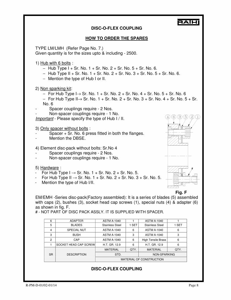
Fig. F EM/EMH -Series disc-pack(Factory assembled): It is a series of blades (5) assembled with caps (2), bushes (3), socket head cap screws (1), special nuts (4) & adapter (6) as shown in fig. F. # - NOT PART OF DISC PACK ASSLY. IT IS SUPPLIED WITH SPACER.
6 ADAPTER ASTM A-1040 1 ASTM A-1040 1
5 BLADES Stainless Steel 1 SET Stainless Steel 1 SET
4 SPECIAL NUT ASTM A-1040 6 ASTM A-1040 6
3 BUSH ASTM A-1040 3 ASTM A-1040 3
2 CAP ASTM A-1040 6 High Tensile Brass 6
1 SOCKET HEAD CAP SCREWS H.T. GR. 12.9 6 H.T. GR. 12.9 6
MATERIAL QTY. MATERIAL QTY.
SR DESCRIPTION STD. NON-SPARKING
MATERIAL OF CONSTRUCTION
DISC-O-FLEX COUPLING
R-PM-D-01/02-01/14 Page 9
HOW TO ORDER THE SPARES
TYPE EM/EMH: (Refer Page No. 8.) Given quantity is for the sizes upto & including – 1880 for EM/EMH Coupling For sizes above, consult RATHI. 1) Standard Bladepack : For ‘EM/EMH’ - Sr. No. 1 + Sr. No. 2 + Sr. No. 3 + Sr. No. 4 + Sr. No. 5 + Sr. No. 6. - Mention the type of Hub I/II or III/IV for EM/EMH.
- 2 Nos. are required per coupling. 2) Non sparking kit :
− Sr. No. 1 + Sr. No. 2 + Sr. No. 3 + Sr. No. 4 + Sr. No. 5 + Sr. No. 6. − Mention the type of Hub I/II or III/IV.
− 2 Nos. are required per coupling. 3) Hub with 6 bolts
− Mention the type of Hub I,II,III or IV. 4) Only spacer without bolts
− Spacer with press fitted bushes (Sr. No. 3) in both the flanges. − Mention the DBSE.
5) Hardware Hub bolts only. - Mention the type of Hub I,II,III or IV.
Disc pack bolts can not be given as spares. In case of the failure in disc-pack bolts, the entire disc-pack has to be replaced.
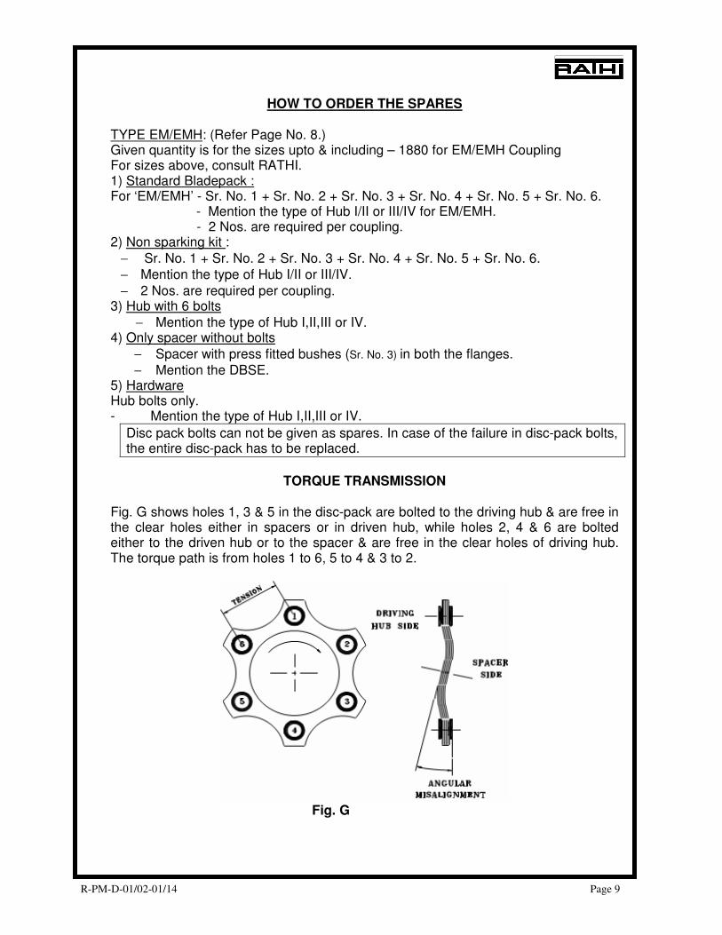
TORQUE TRANSMISSION
Fig. G shows holes 1, 3 & 5 in the disc-pack are bolted to the driving hub & are free in the clear holes either in spacers or in driven hub, while holes 2, 4 & 6 are bolted either to the driven hub or to the spacer & are free in the clear holes of driving hub. The torque path is from holes 1 to 6, 5 to 4 & 3 to 2.
Fig. G
R-PM-D-01/02-01/14 Page 10
DISC-O-FLEX COUPLING
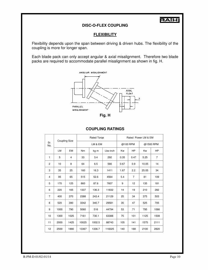
FLEXIBILITY
Flexibility depends upon the span between driving & driven hubs. The flexibility of the coupling is more for longer span. Each blade pack can only accept angular & axial misalignment. Therefore two blade packs are required to accommodate parallel misalignment as shown in fig. H.
Fig. H
COUPLING RATINGS
Rated Torqe Rated Power LM & EM
Coupling Size
LM & EM @100 RPM @1500 RPM Sr. No.
LM EM Nm kg m Lbs-inch Kw HP Kw HP
1 5 4 33 3.4 292 0.35 0.47 5.25 7
2 10 8 64 6.5 566 0.67 0.9 10.05 14
3 35 25 160 16.3 1411 1.67 2.2 25.05 34
4 95 65 515 52.6 4564 5.4 7 81 109
5 170 125 860 87.6 7607 9 12 135 181
6 220 165 1337 136.3 11832 14 19 210 282
7 400 370 2388 243.4 21129 25 34 375 503
8 520 390 3342 340.7 29581 35 47 525 705
9 1000 790 5060 516 44794 53 71 795 1066
10 1300 1025 7161 730.1 63388 75 101 1125 1508
11 2000 1425 10025 1002.5 88743 105 141 1575 2111
12 2500 1880 13367 1336.7 118325 140 188 2100 2820
R-PM-D-01/02-01/14 Page 11
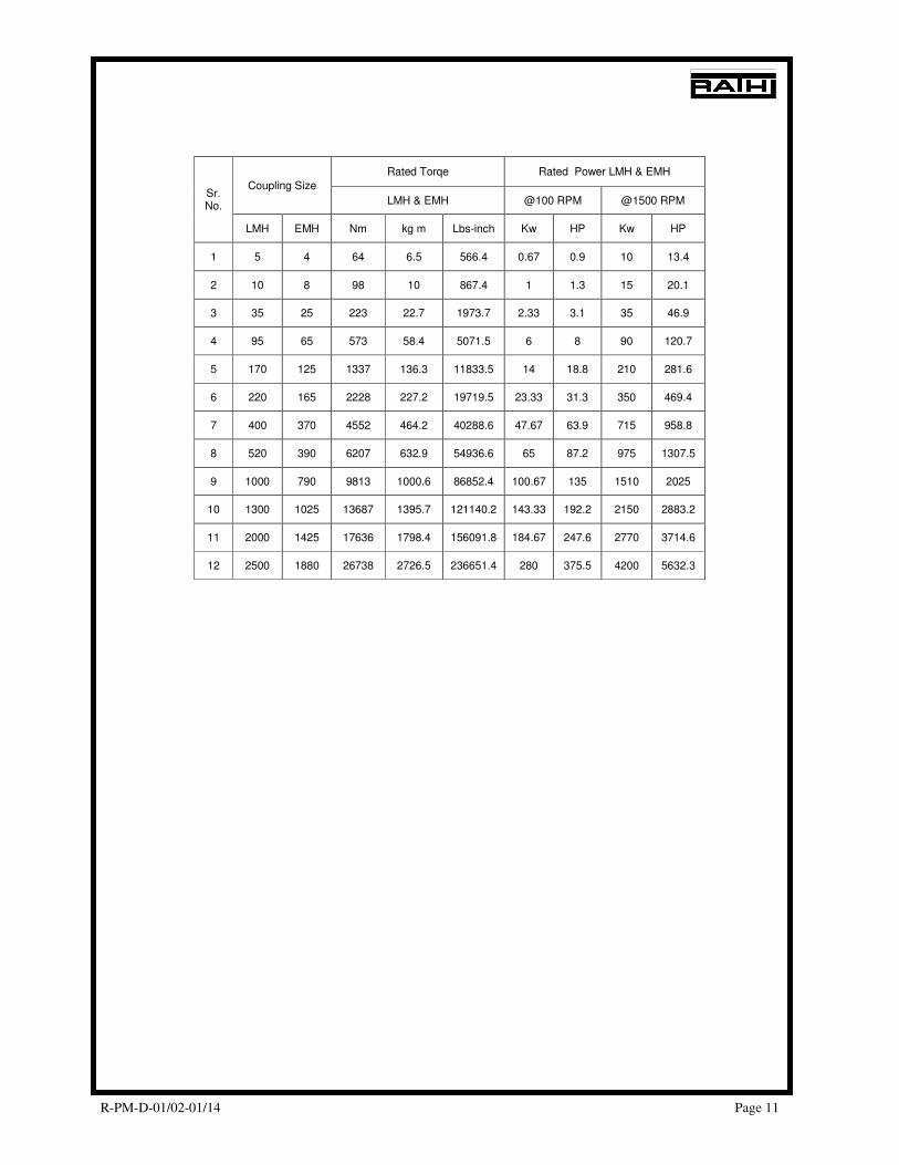
Rated Torqe Rated Power LMH & EMH
Coupling Size
LMH & EMH @100 RPM @1500 RPM Sr. No.
LMH EMH Nm kg m Lbs-inch Kw HP Kw HP
1 5 4 64 6.5 566.4 0.67 0.9 10 13.4
2 10 8 98 10 867.4 1 1.3 15 20.1
3 35 25 223 22.7 1973.7 2.33 3.1 35 46.9
4 95 65 573 58.4 5071.5 6 8 90 120.7
5 170 125 1337 136.3 11833.5 14 18.8 210 281.6
6 220 165 2228 227.2 19719.5 23.33 31.3 350 469.4
7 400 370 4552 464.2 40288.6 47.67 63.9 715 958.8
8 520 390 6207 632.9 54936.6 65 87.2 975 1307.5
9 1000 790 9813 1000.6 86852.4 100.67 135 1510 2025
10 1300 1025 13687 1395.7 121140.2 143.33 192.2 2150 2883.2
11 2000 1425 17636 1798.4 156091.8 184.67 247.6 2770 3714.6
12 2500 1880 26738 2726.5 236651.4 280 375.5 4200 5632.3
R-PM-D-01/02-01/14 Page 12
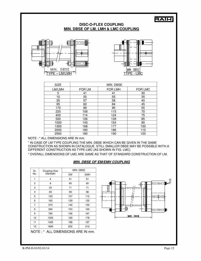
DISC-O-FLEX COUPLING MIN. DBSE OF LM, LMH & LMC COUPLING
TYPE – LM/LMH TYPE - LMC
SIZE MIN. DBSE
LM/LMH FOR LM FOR LMH FOR LMC 5 41 41 30 10 55 55 35 35 57 58 40 95 82 84 45
170 89 95 55 220 108 115 70 400 114 124 75 520 126 139 85
1000 143 154 90 1300 168 177 100 2000 180 186 110 2500 180 190 120
NOTE : * ALL DIMENSIONS ARE IN mm.
* IN CASE OF LM TYPE COUPLING THE MIN. DBSE WHICH CAN BE GIVEN IN THE SAME CONSTRUCTION AS SHOWN IN CATALOGUE. STILL SMALLER DBSE MAY BE POSSIBLE WITH A DIFFERENT CONSTRUCTION AS TYPE-LMC (AS SHOWN IN FIG. LMC)
* OVERALL DIMENSIONS OF LMC ARE SAME AS THAT OF STANDARD CONSTRUCTION OF LM.
MIN. DBSE OF EM/EMH COUPLING
MIN. DBSE Sr. No.
Coupling Size EM/EMH EM EMH
1 4 51 51
2 8 65 65
3 25 71 71
4 65 95 96
5 125 107 112
6 165 129 135
7 370 142 152
8 390 153 165
9 790 156 167
10 1025 169 178
11 1425 188 197
12 1880 202 212
NOTE : * ALL DIMENSIONS ARE IN mm.
R-PM-D-01/02-01/14 Page 13
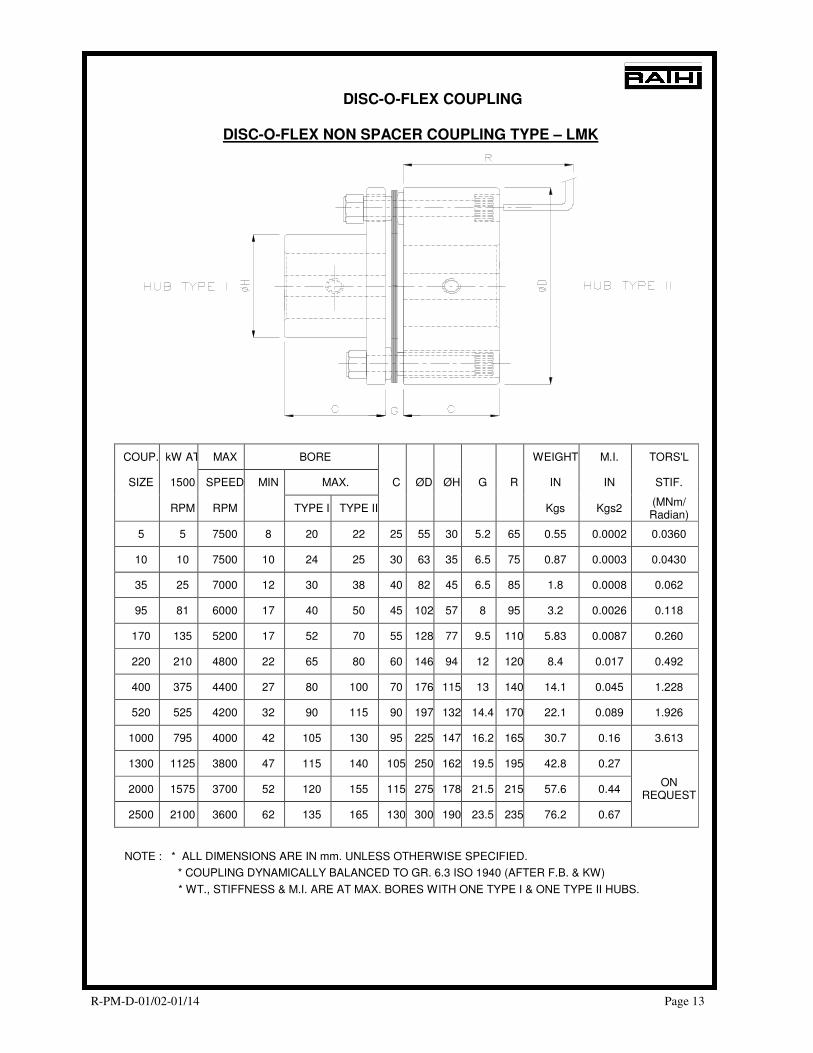
DISC-O-FLEX COUPLING
DISC-O-FLEX NON SPACER COUPLING TYPE – LMK
COUP. kW AT MAX BORE WEIGHT M.I. TORS'L
SIZE 1500 SPEED MIN MAX. IN IN STIF.
RPM RPM TYPE I TYPE II
C ØD ØH G R
Kgs Kgs2 (MNm/ Radian)
5 5 7500 8 20 22 25 55 30 5.2 65 0.55 0.0002 0.0360
10 10 7500 10 24 25 30 63 35 6.5 75 0.87 0.0003 0.0430
35 25 7000 12 30 38 40 82 45 6.5 85 1.8 0.0008 0.062
95 81 6000 17 40 50 45 102 57 8 95 3.2 0.0026 0.118
170 135 5200 17 52 70 55 128 77 9.5 110 5.83 0.0087 0.260
220 210 4800 22 65 80 60 146 94 12 120 8.4 0.017 0.492
400 375 4400 27 80 100 70 176 115 13 140 14.1 0.045 1.228
520 525 4200 32 90 115 90 197 132 14.4 170 22.1 0.089 1.926
1000 795 4000 42 105 130 95 225 147 16.2 165 30.7 0.16 3.613
1300 1125 3800 47 115 140 105 250 162 19.5 195 42.8 0.27
2000 1575 3700 52 120 155 115 275 178 21.5 215 57.6 0.44
2500 2100 3600 62 135 165 130 300 190 23.5 235 76.2 0.67
ON REQUEST
NOTE : * ALL DIMENSIONS ARE IN mm. UNLESS OTHERWISE SPECIFIED.
* COUPLING DYNAMICALLY BALANCED TO GR. 6.3 ISO 1940 (AFTER F.B. & KW)
* WT., STIFFNESS & M.I. ARE AT MAX. BORES WITH ONE TYPE I & ONE TYPE II HUBS.
R-PM-D-01/02-01/14 Page 14
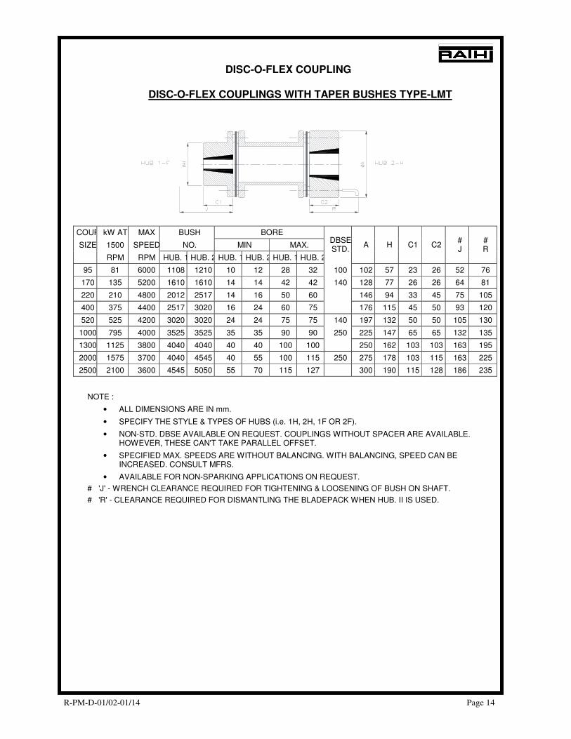
DISC-O-FLEX COUPLING
DISC-O-FLEX COUPLINGS WITH TAPER BUSHES TYPE-LMT
COUP kW AT MAX BUSH BORE
SIZE 1500 SPEED NO. MIN MAX.
RPM RPM HUB. 1 HUB. 2 HUB. 1 HUB. 2 HUB. 1 HUB. 2
DBSESTD.
A H C1 C2 # J
# R
95 81 6000 1108 1210 10 12 28 32 100 102 57 23 26 52 76
170 135 5200 1610 1610 14 14 42 42 140 128 77 26 26 64 81
220 210 4800 2012 2517 14 16 50 60 146 94 33 45 75 105
400 375 4400 2517 3020 16 24 60 75 176 115 45 50 93 120
520 525 4200 3020 3020 24 24 75 75 140 197 132 50 50 105 130
1000 795 4000 3525 3525 35 35 90 90 250 225 147 65 65 132 135
1300 1125 3800 4040 4040 40 40 100 100 250 162 103 103 163 195
2000 1575 3700 4040 4545 40 55 100 115 250 275 178 103 115 163 225
2500 2100 3600 4545 5050 55 70 115 127 300 190 115 128 186 235
NOTE :
• ALL DIMENSIONS ARE IN mm.
• SPECIFY THE STYLE & TYPES OF HUBS (i.e. 1H, 2H, 1F OR 2F).
• NON-STD. DBSE AVAILABLE ON REQUEST. COUPLINGS WITHOUT SPACER ARE AVAILABLE. HOWEVER, THESE CAN'T TAKE PARALLEL OFFSET.
• SPECIFIED MAX. SPEEDS ARE WITHOUT BALANCING. WITH BALANCING, SPEED CAN BE INCREASED. CONSULT MFRS.
• AVAILABLE FOR NON-SPARKING APPLICATIONS ON REQUEST.
# 'J' - WRENCH CLEARANCE REQUIRED FOR TIGHTENING & LOOSENING OF BUSH ON SHAFT.
# 'R' - CLEARANCE REQUIRED FOR DISMANTLING THE BLADEPACK WHEN HUB. II IS USED.

R-PM-D-01/02-01/14 Page 15
DISC-O-FLEX COUPLING
DISC-O-FLEX COUPLINGS WITH TAPER BUSHES TYPE EMT
HUB 1-F HUB 2-H HUB 3-F HUB 4-H
COUPkW AT MAX BUSH MAX. BORE ø ø ø ø # # # #
SIZE 1500 SPEED NO. FOR HUB. TYPES DBSE C1 C2 C3 C4 D1 D2 H1 H2 J1 J2 R1 R2
RPM RPM 1 2 3 4 1 2 3 4
25 25 7000 1108 1210 1610 2012 38 50 48 72 23 26 26 32 90 108 55 70 52 62 76 92
65 81 6000 1610 2012 2012 2517 48 72 65 92 26 32 32 45 108 135 70 86 62 72 92 110
125 135 5200 2012 2517 2517 3020 65 92 80 104 32 45 45 51 135 155 86 108 72 90 110 120
165 210 4800 2517 3020 3020 3020 80 102 90 120 45 51 51 51 152 179 108 130 90 100 120 120
370 375 4400 3020 3020 3525 4040 90 122 108 142 51 51 65 102 182 200 130 158 100 120 120 170
390 525 4200 3525 4040 4040 4545 108 140 127 155 180 65 102 102 115 197 222 158 181 120 165 170 180
790 795 4000 4040 4545 5050 5050 127 158 140 178 250 102 115 127 127 225 250 181 206 165 200 180 195
R-PM-D-01/02-01/14 Page 16
DISC-O-FLEX COUPLING
REQUIREMENTS OF API-671
We offer Disc-o-flex Type EM/EMH coupling in compliance with API-671 with following details. Material of construction - ASTM-1040 (For Hub, Adapter ) ASTM-1040 (For Spacer EM/EMH-4-65) ASTM A-106,ASTM A-105 (For Spacer EM/EMH-125-1880) Component balancing - Gr. 2.5 as per ISO-1940 Service factor - 1.75 (unless otherwise specified) OR Min. 1.25 (with mutual agreement with Purchaser) DBSE - Min. 457 mm. (unless otherwise specified) Can be as per customer’s requirement. Spacer - Anti-Flail (fail safe design) Transmission Unit are removable without disturbing the factory assembled disc-pack which is used in intermediate - or high-speed applications. Eccentricity of hub bore - ≤ 5 microns for bores ≤ 102 mm. ≤ 13 microns for bores ≥ 102 mm. Face runout of mating faces is 25 microns per foot of dia. When specified, electrically insulated (non-sparking) couplings can be given.
REQUIREMENTS OF API-610
Disc-o-flex couplings in compliance with API-610 with following details can be supplied.
• Spacer type Min. DBSE 125 mm. (unless otherwise specified.)
• Dropout spacer.
• DYNAMIC BALANCING TO GR. 2.5
• Coupling hubs with tapped puller holes.
R-PM-D-01/02-01/14 Page 17
DISC-0-FLEX COUPLING
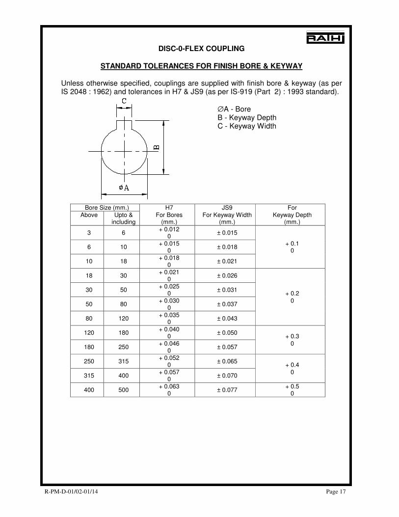
STANDARD TOLERANCES FOR FINISH BORE & KEYWAY
Unless otherwise specified, couplings are supplied with finish bore & keyway (as per IS 2048 : 1962) and tolerances in H7 & JS9 (as per IS-919 (Part 2) : 1993 standard).
∅A - Bore B - Keyway Depth C - Keyway Width
Bore Size (mm.) H7 JS9 For Above Upto &
including For Bores
(mm.) For Keyway Width
(mm.) Keyway Depth
(mm.)
3 6 + 0.012
0 ± 0.015
6 10 + 0.015
0 ± 0.018
+ 0.1 0
10 18 + 0.018
0 ± 0.021
18 30 + 0.021
0 ± 0.026
30 50 + 0.025
0 ± 0.031
+ 0.2
50 80 + 0.030
0 ± 0.037
0
80 120 + 0.035
0 ± 0.043
120 180 + 0.040
0 ± 0.050
+ 0.3
180 250 + 0.046
0 ± 0.057
0
250 315 + 0.052
0 ± 0.065
+ 0.4
315 400 + 0.057
0 ± 0.070
0
400 500 + 0.063
0 ± 0.077
+ 0.5 0
R-PM-D-01/02-01/14 Page 18
DISC-O-FLEX COUPLING
SELECTION PROCEDURE
Requirements
Application : Driver - Driven - Application Rating : kW - RPM - Shaft sizes : Driver - Driven - Distance between shaft ends (DBSE) : Service Factor (S.F.) to be taken : Selection Procedure a) Service Factor Determine appropriate SERVICE FACTOR from service factor table given in catalogue. (b) Design Power Multiply running power of driven machinery by the service factor. This gives DESIGN POWER which is used as a basis for coupling selection. (c) Coupling Size Refer to rating table in catalogue for your required coupling size and read from the appropriate speed column until a power equal to or greater than the DESIGN POWER is found. (d) Bore size Refer respective coupling dimensional table to check that the required bores can be accommodated. Select the type of Hubs accordingly. Possible combination of Hubs are Hub type I/I, I/II, II/II, III/III, III/IV & IV/IV only. If bore sizes of selected coupling can’t accommodate the shaft sizes, then go for next coupling size till shaft sizes can be accommodated.
R-PM-D-01/02-01/14 Page 19
DISC-O-FLEX COUPLING
APPLICATIONS
Equipments: Agitators, Hammer mills, Blowers Line shafts, Conveyors, Machine tools, Crushers, Metal forming machines, Elevators, Mixers, Escalators, Pulverisers, Extruders, Pumps, Feeders, Screens, Generators, Wenches. Industries: Cement Brewing & Distilling Food, Rolling Mills, Oil & Petroleum, Chemical & Fertiliser, Paper Mills, Rubber, Sewage Disposal, Sugar, Textile, Thermal Power Houses.
R-PM-D-01/02-01/14 Page 20
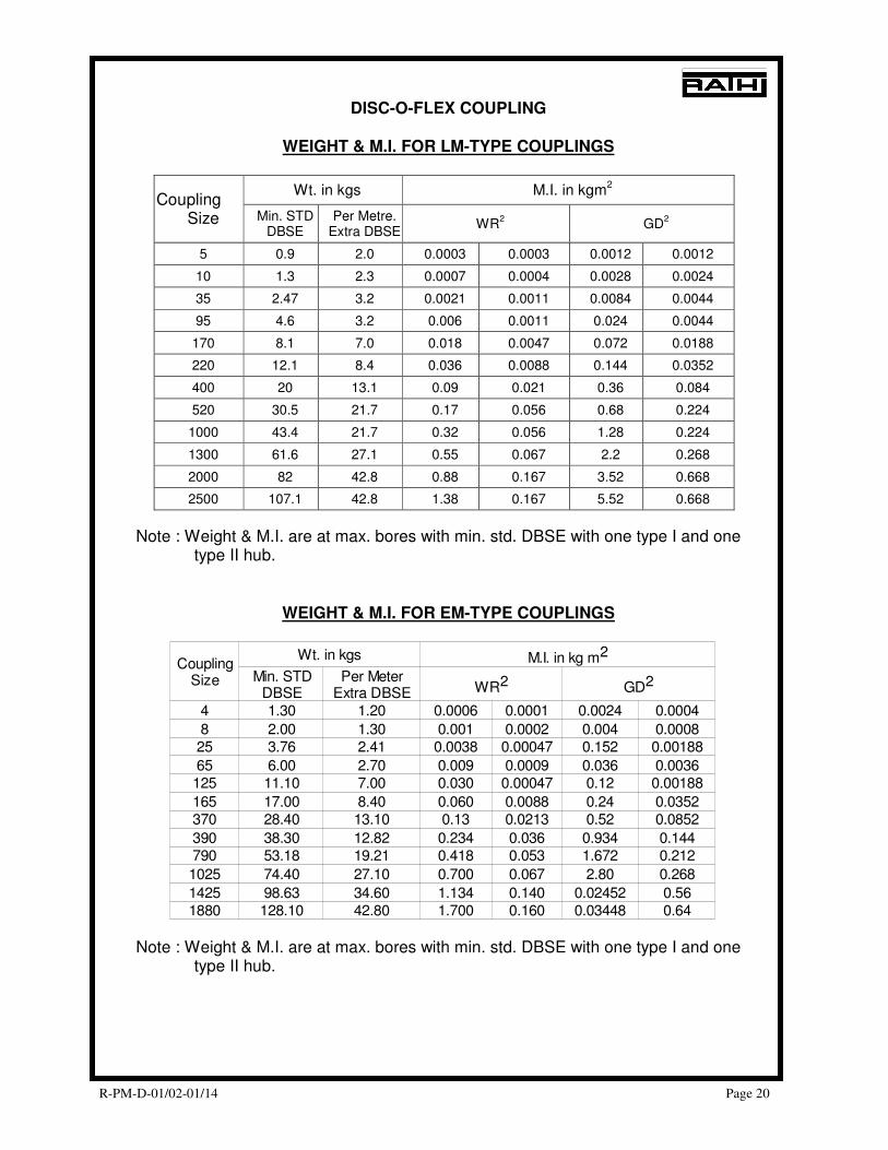
DISC-O-FLEX COUPLING
WEIGHT & M.I. FOR LM-TYPE COUPLINGS
Wt. in kgs M.I. in kgm2
Coupling Size Min. STD
DBSE Per Metre.
Extra DBSE WR
2 GD
2
5 0.9 2.0 0.0003 0.0003 0.0012 0.0012
10 1.3 2.3 0.0007 0.0004 0.0028 0.0024
35 2.47 3.2 0.0021 0.0011 0.0084 0.0044
95 4.6 3.2 0.006 0.0011 0.024 0.0044
170 8.1 7.0 0.018 0.0047 0.072 0.0188
220 12.1 8.4 0.036 0.0088 0.144 0.0352
400 20 13.1 0.09 0.021 0.36 0.084
520 30.5 21.7 0.17 0.056 0.68 0.224
1000 43.4 21.7 0.32 0.056 1.28 0.224
1300 61.6 27.1 0.55 0.067 2.2 0.268
2000 82 42.8 0.88 0.167 3.52 0.668
2500 107.1 42.8 1.38 0.167 5.52 0.668
Note : Weight & M.I. are at max. bores with min. std. DBSE with one type I and one type II hub.
WEIGHT & M.I. FOR EM-TYPE COUPLINGS
Note : Weight & M.I. are at max. bores with min. std. DBSE with one type I and one type II hub.
Wt. in kgs
4 1.30 1.20 0.0006 0.0001 0.0024 0.0004
8 2.00 1.30 0.001 0.0002 0.004 0.000825 3.76 2.41 0.0038 0.00047 0.152 0.00188
65 6.00 2.70 0.009 0.0009 0.036 0.0036125 11.10 7.00 0.030 0.00047 0.12 0.00188
165 17.00 8.40 0.060 0.0088 0.24 0.0352370 28.40 13.10 0.13 0.0213 0.52 0.0852
390 38.30 12.82 0.234 0.036 0.934 0.144790 53.18 19.21 0.418 0.053 1.672 0.212
1025 74.40 27.10 0.700 0.067 2.80 0.268
1425 98.63 34.60 1.134 0.140 0.02452 0.561880 128.10 42.80 1.700 0.160 0.03448 0.64
CouplingSize
M.I. in kg m2
Min. STDDBSE
Per MeterExtra DBSE WR2 GD2
R-PM-D-01/02-01/14 Page 21
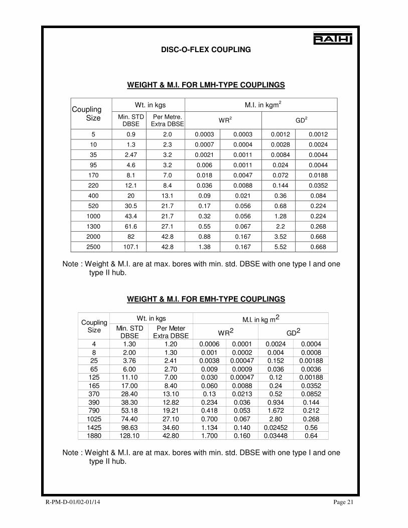
DISC-O-FLEX COUPLING
WEIGHT & M.I. FOR LMH-TYPE COUPLINGS
Wt. in kgs M.I. in kgm2
Coupling Size Min. STD
DBSE Per Metre.
Extra DBSE WR
2 GD
2
5 0.9 2.0 0.0003 0.0003 0.0012 0.0012
10 1.3 2.3 0.0007 0.0004 0.0028 0.0024
35 2.47 3.2 0.0021 0.0011 0.0084 0.0044
95 4.6 3.2 0.006 0.0011 0.024 0.0044
170 8.1 7.0 0.018 0.0047 0.072 0.0188
220 12.1 8.4 0.036 0.0088 0.144 0.0352
400 20 13.1 0.09 0.021 0.36 0.084
520 30.5 21.7 0.17 0.056 0.68 0.224
1000 43.4 21.7 0.32 0.056 1.28 0.224
1300 61.6 27.1 0.55 0.067 2.2 0.268
2000 82 42.8 0.88 0.167 3.52 0.668
2500 107.1 42.8 1.38 0.167 5.52 0.668
Note : Weight & M.I. are at max. bores with min. std. DBSE with one type I and one type II hub.
WEIGHT & M.I. FOR EMH-TYPE COUPLINGS
Note : Weight & M.I. are at max. bores with min. std. DBSE with one type I and one type II hub.
Wt. in kgs
4 1.30 1.20 0.0006 0.0001 0.0024 0.0004
8 2.00 1.30 0.001 0.0002 0.004 0.000825 3.76 2.41 0.0038 0.00047 0.152 0.00188
65 6.00 2.70 0.009 0.0009 0.036 0.0036125 11.10 7.00 0.030 0.00047 0.12 0.00188
165 17.00 8.40 0.060 0.0088 0.24 0.0352370 28.40 13.10 0.13 0.0213 0.52 0.0852
390 38.30 12.82 0.234 0.036 0.934 0.144790 53.18 19.21 0.418 0.053 1.672 0.212
1025 74.40 27.10 0.700 0.067 2.80 0.268
1425 98.63 34.60 1.134 0.140 0.02452 0.561880 128.10 42.80 1.700 0.160 0.03448 0.64
CouplingSize
M.I. in kg m2
Min. STDDBSE
Per MeterExtra DBSE WR2 GD2
R-PM-D-01/02-01/14 Page 22
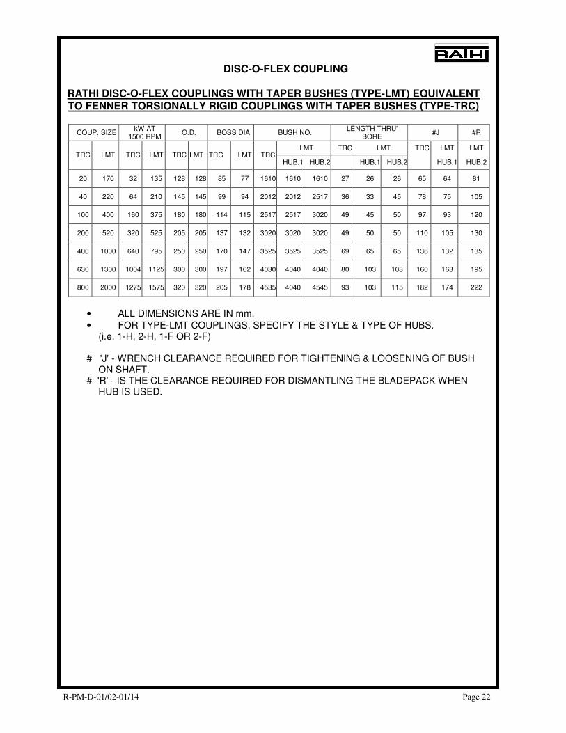
DISC-O-FLEX COUPLING
RATHI DISC-O-FLEX COUPLINGS WITH TAPER BUSHES (TYPE-LMT) EQUIVALENT TO FENNER TORSIONALLY RIGID COUPLINGS WITH TAPER BUSHES (TYPE-TRC)
COUP. SIZE kW AT
1500 RPM O.D. BOSS DIA BUSH NO.
LENGTH THRU' BORE
#J #R
LMT TRC LMT TRC LMT LMT TRC LMT TRC LMT TRC LMT TRC LMT TRC
HUB.1 HUB.2 HUB.1 HUB.2 HUB.1 HUB.2
20 170 32 135 128 128 85 77 1610 1610 1610 27 26 26 65 64 81
40 220 64 210 145 145 99 94 2012 2012 2517 36 33 45 78 75 105
100 400 160 375 180 180 114 115 2517 2517 3020 49 45 50 97 93 120
200 520 320 525 205 205 137 132 3020 3020 3020 49 50 50 110 105 130
400 1000 640 795 250 250 170 147 3525 3525 3525 69 65 65 136 132 135
630 1300 1004 1125 300 300 197 162 4030 4040 4040 80 103 103 160 163 195
800 2000 1275 1575 320 320 205 178 4535 4040 4545 93 103 115 182 174 222
• ALL DIMENSIONS ARE IN mm.
• FOR TYPE-LMT COUPLINGS, SPECIFY THE STYLE & TYPE OF HUBS. (i.e. 1-H, 2-H, 1-F OR 2-F)
# 'J' - WRENCH CLEARANCE REQUIRED FOR TIGHTENING & LOOSENING OF BUSH
ON SHAFT. # 'R' - IS THE CLEARANCE REQUIRED FOR DISMANTLING THE BLADEPACK WHEN
HUB IS USED.
R-PM-D-01/02-01/14 Page 23
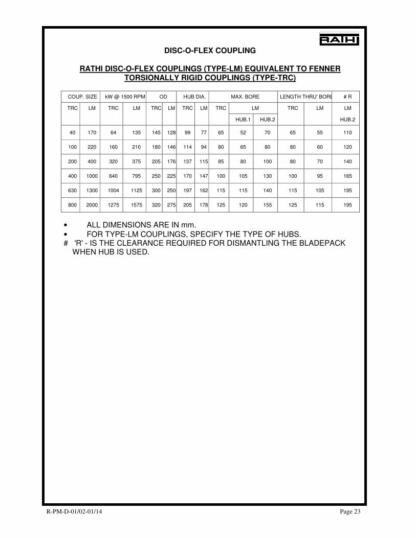
DISC-O-FLEX COUPLING
RATHI DISC-O-FLEX COUPLINGS (TYPE-LM) EQUIVALENT TO FENNER TORSIONALLY RIGID COUPLINGS (TYPE-TRC)
COUP. SIZE kW @ 1500 RPM OD HUB DIA. MAX. BORE LENGTH THRU' BORE # R
TRC LM TRC LM TRC LM TRC LM TRC LM TRC LM LM
HUB.1 HUB.2 HUB.2
40 170 64 135 145 128 99 77 65 52 70 65 55 110
100 220 160 210 180 146 114 94 80 65 80 80 60 120
200 400 320 375 205 176 137 115 85 80 100 80 70 140
400 1000 640 795 250 225 170 147 100 105 130 100 95 165
630 1300 1004 1125 300 250 197 162 115 115 140 115 105 195
800 2000 1275 1575 320 275 205 178 125 120 155 125 115 195
• ALL DIMENSIONS ARE IN mm.
• FOR TYPE-LM COUPLINGS, SPECIFY THE TYPE OF HUBS. # 'R' - IS THE CLEARANCE REQUIRED FOR DISMANTLING THE BLADEPACK
WHEN HUB IS USED.
R-PM-D-01/02-01/14 Page 24
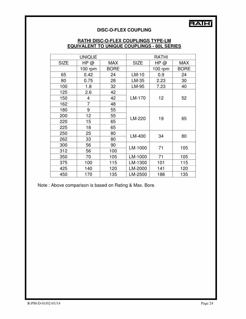
DISC-O-FLEX COUPLING
RATHI DISC-O-FLEX COUPLINGS TYPE-LM EQUIVALENT TO UNIQUE COUPLINGS - 80L SERIES
UNIQUE RATHI
SIZE HP @ MAX SIZE HP @ MAX
100 rpm BORE 100 rpm BORE
65 0.42 24 LM-10 0.9 24
80 0.75 28 LM-35 2.23 30
100 1.8 32 LM-95 7.23 40
125 2.6 42
150 4 42
162 7 48
LM-170 12 52
180 9 55
200 12 55
220 15 65
225 18 65
LM-220 19 65
250 25 80
262 33 80 LM-400 34 80
300 56 90
312 56 100 LM-1000 71 105
350 70 105 LM-1000 71 105
375 100 115 LM-1300 101 115
425 140 120 LM-2000 141 120
450 170 135 LM-2500 188 135
Note : Above comparison is based on Rating & Max. Bore.
R-PM-D-01/02-01/14 Page 25
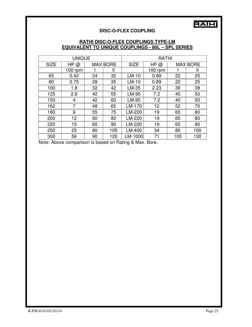
DISC-O-FLEX COUPLING
RATHI DISC-O-FLEX COUPLINGS TYPE-LM EQUIVALENT TO UNIQUE COUPLINGS - 80L – SPL SERIES
UNIQUE RATHI
SIZE HP @ MAX BORE SIZE HP @ MAX BORE 100 rpm I II 100 rpm I II
65 0.42 24 32 LM-10 0.89 22 25
80 0.75 28 35 LM-10 0.89 22 25
100 1.8 32 42 LM-35 2.23 30 38
125 2.6 42 55 LM-95 7.2 40 50
150 4 42 60 LM-95 7.2 40 50
162 7 48 65 LM-170 12 52 70
180 9 55 75 LM-220 19 65 80
200 12 60 80 LM-220 19 65 80
220 15 65 90 LM-220 19 65 80
250 25 80 105 LM-400 34 80 100
300 56 90 120 LM-1000 71 105 130
Note: Above comparison is based on Rating & Max. Bore.
R-PM-D-01/02-01/14 Page 26
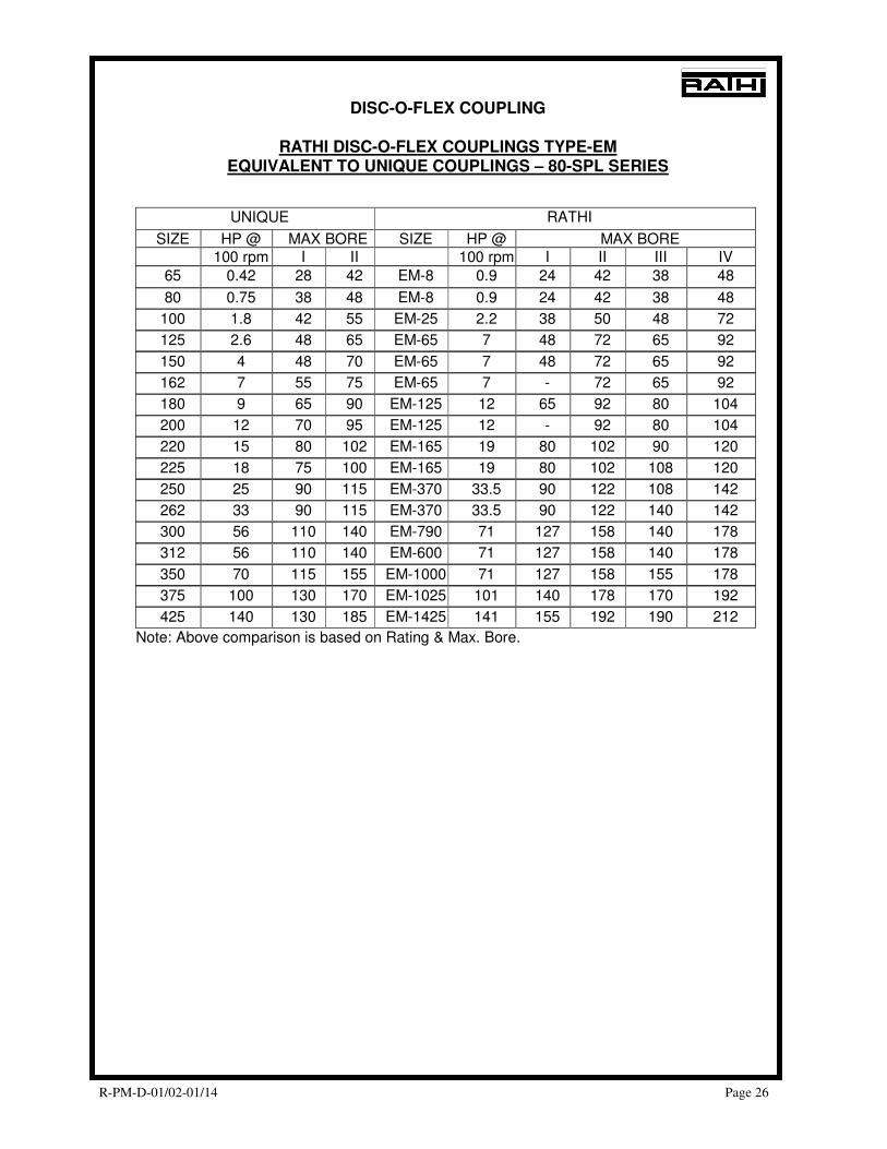
DISC-O-FLEX COUPLING
RATHI DISC-O-FLEX COUPLINGS TYPE-EM EQUIVALENT TO UNIQUE COUPLINGS – 80-SPL SERIES
UNIQUE RATHI
SIZE HP @ MAX BORE SIZE HP @ MAX BORE 100 rpm I II 100 rpm I II III IV
65 0.42 28 42 EM-8 0.9 24 42 38 48
80 0.75 38 48 EM-8 0.9 24 42 38 48
100 1.8 42 55 EM-25 2.2 38 50 48 72
125 2.6 48 65 EM-65 7 48 72 65 92
150 4 48 70 EM-65 7 48 72 65 92
162 7 55 75 EM-65 7 - 72 65 92
180 9 65 90 EM-125 12 65 92 80 104
200 12 70 95 EM-125 12 - 92 80 104
220 15 80 102 EM-165 19 80 102 90 120
225 18 75 100 EM-165 19 80 102 108 120
250 25 90 115 EM-370 33.5 90 122 108 142
262 33 90 115 EM-370 33.5 90 122 140 142
300 56 110 140 EM-790 71 127 158 140 178
312 56 110 140 EM-600 71 127 158 140 178
350 70 115 155 EM-1000 71 127 158 155 178
375 100 130 170 EM-1025 101 140 178 170 192
425 140 130 185 EM-1425 141 155 192 190 212
Note: Above comparison is based on Rating & Max. Bore.
R-PM-D-01/02-01/14 Page 27
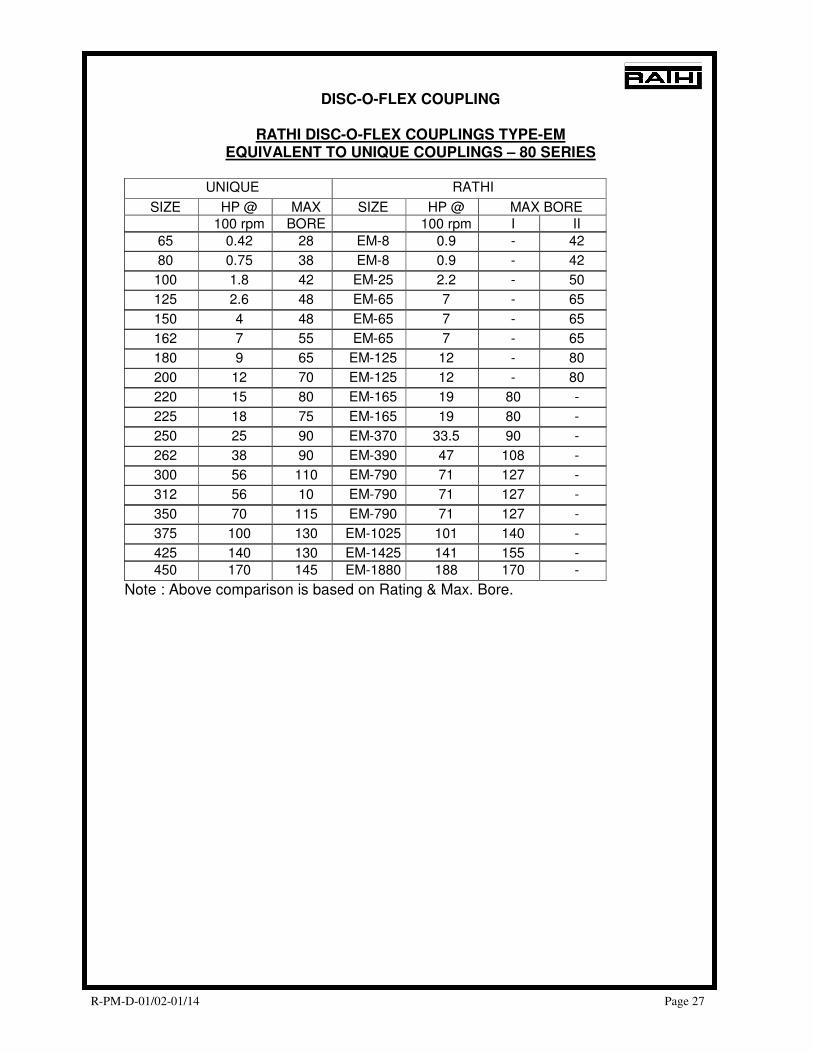
DISC-O-FLEX COUPLING
RATHI DISC-O-FLEX COUPLINGS TYPE-EM EQUIVALENT TO UNIQUE COUPLINGS – 80 SERIES
UNIQUE RATHI
SIZE HP @ MAX SIZE HP @ MAX BORE 100 rpm BORE 100 rpm I II
65 0.42 28 EM-8 0.9 - 42
80 0.75 38 EM-8 0.9 - 42
100 1.8 42 EM-25 2.2 - 50
125 2.6 48 EM-65 7 - 65
150 4 48 EM-65 7 - 65
162 7 55 EM-65 7 - 65
180 9 65 EM-125 12 - 80
200 12 70 EM-125 12 - 80
220 15 80 EM-165 19 80 -
225 18 75 EM-165 19 80 -
250 25 90 EM-370 33.5 90 -
262 38 90 EM-390 47 108 -
300 56 110 EM-790 71 127 -
312 56 10 EM-790 71 127 -
350 70 115 EM-790 71 127 -
375 100 130 EM-1025 101 140 -
425 140 130 EM-1425 141 155 -
450 170 145 EM-1880 188 170 -
Note : Above comparison is based on Rating & Max. Bore.
R-PM-D-01/02-01/14 Page 28
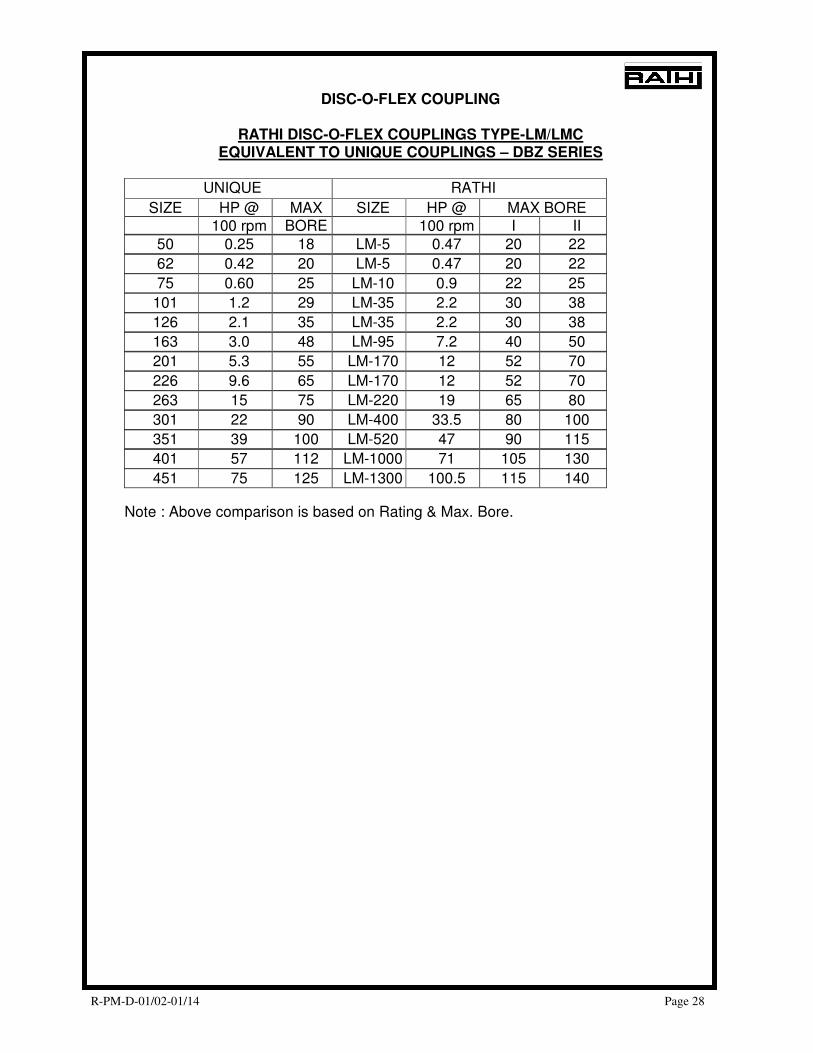
DISC-O-FLEX COUPLING
RATHI DISC-O-FLEX COUPLINGS TYPE-LM/LMC EQUIVALENT TO UNIQUE COUPLINGS – DBZ SERIES
UNIQUE RATHI
SIZE HP @ MAX SIZE HP @ MAX BORE 100 rpm BORE 100 rpm I II
50 0.25 18 LM-5 0.47 20 22
62 0.42 20 LM-5 0.47 20 22
75 0.60 25 LM-10 0.9 22 25
101 1.2 29 LM-35 2.2 30 38
126 2.1 35 LM-35 2.2 30 38
163 3.0 48 LM-95 7.2 40 50
201 5.3 55 LM-170 12 52 70
226 9.6 65 LM-170 12 52 70
263 15 75 LM-220 19 65 80
301 22 90 LM-400 33.5 80 100
351 39 100 LM-520 47 90 115
401 57 112 LM-1000 71 105 130
451 75 125 LM-1300 100.5 115 140
Note : Above comparison is based on Rating & Max. Bore.