product manufacturing and cost estimating using cad/cae || virtual machining
TRANSCRIPT

Virtual Machining
CHAPTER
2
CHAPTER OUTLINE
41
42
42
46
48
51
51
52
56
61
62
63
64
67
69
69
70
72
72
76
80
81
83
84
85
86
86
87
21 Introduction
22 NC Part Programming
221 Basics of NC Machines
222 Basic Concept of Part Programming
223 Computer-Assisted Part Programming
224 CADCAM Approach
23 Virtual Machining Simulations
231 Basic Machining Simulations
232 Advanced Machining Simulations
233 Turning Simulations
24 Practical Aspects in CNC Machining
241 Jigs and Fixtures
242 Cutters and Machining Parameters
243 Setting a CNC Sequence
25 Commercial Machining Simulation Software
251 General-Purpose Machining Software
252 Special-Purpose Machining Software
26 Case Study and Tutorial Examples
261 Case Study
262 Tutorial Examples
27 Summary
Questions and Exercises
References
Appendix A Sample Address Codes
Appendix B Sample G- and M-Codes
Appendix C HAAS Mini-Mill
Basic Machine Configuration
Prestart and Power-Up
In product development it is highly desirable that the manufacturability of the individual parts andthe overall assembly be verified prior to functional prototyping and production Discoveringmanufacturing-related issues during the late stages causes delay in bringing the product to market andincreases product development cost It is essential to address manufacturability issues during the
Product Manufacturing and Cost Estimating using CADCAE httpdxdoiorg101016B978-0-12-401745-000002-2
Copyright 2013 Elsevier Inc All rights reserved39
40 CHAPTER 2 Virtual Machining
product design stage and it is effective to address such issues using virtual manufacturing technologyand software tools
Virtual manufacturing is the use of simulation-based technology to aid engineers in definingsimulating and visualizing the manufacturing process of a product in a computer environment Byusing virtual manufacturing the manufacturing process can be defined and verified early in the designstage Some if not all of the potential manufacturing-related issues can be detected and addressedwhile the design is still being finalized In addition manufacturing cost and time which constitutea significant portion of the product cost can be estimated
Virtual manufacturing is a broad subject that involves a substantial range of topics Instead ofaddressing broad aspects of manufacturing technology and process we will focus in this chapter onthe machining operations of virtual manufacturing such as milling turning and drilling namelyvirtual machining (VM) In addition sheet forming simulation which is recently gaining morepopularity in industry will be discussed in Chapter 4
Virtual machining allows designers to conduct machining process planning generate machiningtoolpaths visualize and simulate machining operations and estimate machining time Moreover thetoolpath generated can be converted into CNC codes (M-codes and G-codes) to machine functionalparts as well as die or mold for production One of the main considerations in discussing virtualmachining in this chapter is that CNC machining has a relatively low setup cost compared to theforming molding or casting process In general CNC machines are relatively accessible to smallbusiness and academia Furthermore CNC is cost effective for low-volume production which is idealin support of physical or functional prototyping
In most cases the toolpath is generated in a so-called CL (cutter location) data format and thenconverted to CNC codes using corresponding post-processors In addition to basic VM simulations wewill briefly discuss CNC codes or part programming to help you become familiar with and be able toread (and hopefully edit and write) CL data and CNC codes
Although ldquoVirtual Machiningrdquo is the title of this chapter we will include a few practical aspects ofusing CNC mill for machining We will discuss choosing essential machining parameters such asfeedrate and spindle speed in addition to cutter and fixture selections We will also present a generalprocess to set up a machining job using a HAAS 3-axis mill as a practical example
Machining of dies that support die casting for tracked vehicle roadarms is included as an example toillustrate and demonstrate the application of VM to a practical engineering design In addition threepractice examplesdprofile milling volume milling and surface millingdusing both ProMFG (wwwptccomproductcreomachining-extension) and Mastercam (wwwmastercamcom) will be discussedSome of these practice examples can also be found in the tutorial lessons which include CAMWorks(wwwcamworkscom) in addition toProMFGandMastercamDetailed instructions for bringingup thesemodels and steps for carryingout theVMdiscussed in this chapter can be found inProjects P4M4 andS4for ProMFG Mastercam and CAMWorks respectively Example models are available for download atthe bookrsquos companion website (httpbooksiteelseviercom9780124017450)
This chapter was written with the assumption that readers are familiar with basic manufacturingprocesses especially machining Details related to basic milling turning and hole making can befound in other textbooks such as Manufacturing Engineering amp Technology 6 ed by SeropeKalpakjian and Steven R Schmid (see references at the end of this chapter) In addition we encouragereaders to review excellent NC programming books (such as Smid 2000) before going over thischapter
21 Introduction 41
The overall objectives of this chapter are to (a) provide you with a general understanding of virtualmachining simulations and how to employ virtual machining software to support product design (b)become familiar with existing commercial software for VM and (c) be able to use ProMFGMastercam or CAMWorks for basic machining jobs (after going through the tutorial lessons)
21 INTRODUCTIONIn the mechanical and aerospace industries engineers often confront the challenge of designingcomponents that are capable of sustaining structural loads and meeting functional requirements It isimperative that these components contain minimum material to reduce cost and increase the efficiencyof the mechanical system in terms of for example fuel consumption of a ground vehicle Thegeometry of these components is usually complicated due to strength and efficiency requirementswhich often results in increased manufacturing time and cost Other significant issues (eg machin-ability characterized by surface finish tool (cutter) life and force and power requirements) add to thechallenges that designers must confront In product design it is essential that parts designed can bemanufactured or machined with regular and off-the-shelf set ups and in the shortest time possible sincemachining time directly impacts product costs
Various manufacturing processes and technologies are suitable for part manufacturing includingcasting forming molding sintering and machining which have been well documented (Kalpakjianand Schmid 2010) Among them most machining has a relatively low setup cost compared to formingmolding and casting processes Consequently CNC machines are relatively accessible to smallbusinesses and academia In addition CNC is cost effective for low-volume production which is idealfor physical or functional prototyping
In line with the main theme of the book this chapter focuses on virtual machining which is the useof simulation-based technology to aid designers in conducting machining process planning in a virtualenvironment generating machining toolpath visualizing and simulating the machining operationsand estimating machining time
Simulation of a mold machining is illustrated in Figure 21 where three NC sequences aredefined The first sequence creates a smooth flat surface on top of the workpiece that is face milling
Stair type surface
Scallop remained on the surface
Cutter
(a) (b) (c)
FIGURE 21
Virtual machining for a cover die (a) face milling (b) volume milling (rough cut) and (c) contour surface milling
(finish cut)
42 CHAPTER 2 Virtual Machining
The second sequence cuts the cavity (a rough cut) and generates a stair-type surface which is notsmooth Note that the distance between the stair layers is controlled by a machining parameter calledstep depthdset to be 01 in in this case The third sequence uses a contour surface milling topolish the cavityrsquos surface (a finish cut) This minimizes the grinding operation and increasesaccuracy of the die
As illustrated in Figure 21c after the three NC sequences the cavity surface is still not completelysmoothdscallop and tool marks are clearly visible Themaximum scallop height is computed as less than005 in The size of the scallop remaining on the cavity surface can be reduced by using a smaller stepoveror a smaller size cutter in the finish cutMachining timewillmost likely increase using eitherway The toolmarks canbe removedbykeeping a small layer of thematerial on thebottomfaceof the cavityuncut duringthe rough cut Usually grinding operations are employed to further polish the cavityrsquos surface
In this chapter we will start by a short and brief introduction on NC part programming thenfollowed by a few virtual machining examples After reviewing these two topics you should havea fairly complete picture of virtual machining We will then discuss a few important points you shouldbe aware of in CNC machining from a practical perspectives This will help you create valid CNCcodes and take practical issues into consideration We will also discuss commercially availablemachining simulation software tools which should help you make an adequate selection suitable foryour needs This chapter wraps up by introducing a case study that involves virtual machining fora tracked vehicle roadarm In addition tutorial examples are provided
22 NC PART PROGRAMMINGNC part programming creates NC codes which provide the instructions that drive cutters and controlmachine operations In general there are three approaches supporting NC programming manualcomputer-assisted and CADCAM In this section we will first briefly go over these approaches Wefocus on the CADCAM approach in the remainder of the chapter Before introducing NC partprogramming we will provide a brief discussion on NC machines coordinate systems type ofmachines and type of machining operation in NC
221 Basics of NC Machines
The difference between NC machines and conventional machines is in the way in which the variousfunctions and cutter movements are controlled In conventional machines these are controlled by shopmechanists In NC these motions are controlled by the machine control unit (MCU) as depicted inFigure 22
The MCU (brain of the NC) consists of a DPU (data processing unit) and a CLU (control loopunit) DPU reads the part program from tape or some other media and decodes the part programstatements processes the decoded information and passes information to the CLU The informationincludes position of each axis of the machine its direction of motion feedrate and auxiliaryfunction control signals (eg coolant on or off) CLU receives data from the DPU converts them tocontrol signals and controls the machine via actuation devices that replace the hand wheel of theconventional machine An actuation device could be a servomotor a hydraulic actuator or a stepmotor A servomotor (servo) is an electromechanical device in which an electrical input determines
Machinetool
Storedprogram
Actuationdevices
Pointer
Spindle
Drive Motor
Drive Motor Signal
MCU
Leadscrew
Machine control unit (MCU)
Table
Table
Spindle
Slide
Movement
Feedback Signal
Feedback
Device
Handwheel Dial
(c)(b)(a)
FIGURE 22
Configuration of a typical NC machine (a) the machine control unit (b) hand wheel dial and (c) closed-loop
control
22 NC Part Programming 43
the position of the armature of a motor Servos are used extensively in robotics and radio-controlledcars airplanes and boats
The MCU gives instructions to the servo system monitors both the position and velocity output ofthe system and uses this feedback to compensate for errors between the program command and thesystem response The instructions given to the servos are modified according to the measured responseof the system called closed-loop control
Each axis of motion is equipped with a driving (actuation) device The primary three axes ofmotion are referred to as the X- Y- and Z-axes They form the machine tool coordinate system TheXYZ system is a right-hand system and the location of its original may be fixed (older machine) oradjustable (floating zero)
The Z-axis is the most important axis for machining This axis is always aligned with the spindlethat imparts power as shown in Figure 23 The spindle may rotate workpiece such as in a lathe or it
FIGURE 23
XYZ system mill (HAAS)
Tool startingpoint
Toolpath
Toolpath
Tool startingpoint
X
Y Workpiece (a) (b)
X
Y
Workpiece
FIGURE 24
Types of NC machines (a) point-to-point and (b) continuous path
44 CHAPTER 2 Virtual Machining
may rotate a tool as in a milling machine Usually the direction that moves away from the workpiece isdefined as positive
On a workpiece-rotating machine (eg lathe) the X-axis is the direction of tool movement anda motion along its positive direction moves the tool away from the workpiece On a milling or drillingmachine the positive X-axis points to the right when the programmer is facing the machine Note thatthe definition of the positive X-axis is not universal Y-axis is determined by X- and Z-axes through theright-hand rule W-axis (less common) is parallel to Z-axes but points in the opposite direction
There are several ways to categorize NC machines By looking at its cutting path a NC machinecan be a PTP (point-to-point) or continuous path (Figure 24) For a PTP machine cutter performsoperations on the workpiece at specific points The cutter is not always in contact with the workpiecethroughout its motion or its path The exact path the tool takes in moving from point to point is ingeneral immaterial (except that tool-traveling time must be minimized and not collide with work-piece and fixtures) A hole-drilling machine is a good PTP example On the other hand fora continuous path NC the cutter is mostly in contact with the workpiece during its motion or its pathThe workpiece is being affected throughout the toolpath The entire travel of the cutting tool must becontrolled to close accuracy as to both position and velocity In general mill and lathe are in thiscategory
Another way of categorizing NC machines is by the type of controller unit installed on them Thedata processing unit on a conventional NC machine is a tape reader which reads punched tape in 8-bitformat this is the oldest and is rarely used now A CNC (computer numerical control) comes witha dedicated CPU monitor and local memory Instructions can be generated directly from a computerand downloaded to the machine Instructions can also be directly programmed on the CNC machineThe HAAS mill included in Appendix C is a CNC A group of CNCs also can be networked andcontrolled by a central computer This type of setup is called DNC (distributed numerical control)which is often seen on a shop floor
Among all the most common ways to classify NC machines is by the number of axes that thecontrol drives simultaneously to move and rotate the cutter with respect to workpiece or vice versaTwo-axis NC refers to machines that control cutter motion simultaneously along two orthogonaldirections in a plane (ie X- and Y-axes) The cutter is independently controlled along the third axisusually the Z-axis Z-axis control is parallel to the normal direction of the X-Y plane Machine
(a) (b)
(c) (d)
FIGURE 25
CNC machines of 2 to 5 axes (a) water jet (Dix Metals wwwyoutubecomwatchvfrac14crgujRcyhhEampfeaturefrac14player_embedded) 2 axes (b) HAAS 3-axis CNC mill (c) 4th axis rotary table from Techno (d) gear cutting
using special 5-axis mill (wwwamtek-precisioncom)
22 NC Part Programming 45
supporting processes such as turning drilling punching and profiling belong to a two-axis NCIn addition a plasma cutter such as PlasmaCAM (see images at wwwplasmacamcomindexflaphp)and a waterjet (see youTube video wwwyoutubecomwatchv=crgujRcyhhEampfeature=player_embedded) are popular 2-axis NC machines
Three-axis motion is most common in many aspects The cutter is generally controlled in threeprincipal directions of the Cartesian coordinate system simultaneously A three-axis machine is able tocut not only pockets profiles and holes but also sculpture (or freeform) surfaces often seen in mold ordie manufacturing For example an ejector die shown in Figure 25b was machined using a HAAS3-axis mill
An add-on 4th axis rotary table can convert an existing 3-axis mill center into a full 4-axis CNCmachine The rotary table allows spindle access to the workpiece from various angles in one setup thatmight take several setups with a conventional 3-axis machine (as shown in Figure 25c)
A 5-axis CNC mill in general provides simultaneous motion control in three linear directions (X-Y- and Z-axes) and two rotations which usually are C (about Z-axis) and A (about X-axis) or C and B(about Y-axis) Such powerful machines support manufacturing a diverse range of components such asgear (Figure 25d) and turbine blades (see image at wwwthesurfacegrindercom) to varying degrees ofcomplexity and tolerances for high precision industries
46 CHAPTER 2 Virtual Machining
222 Basic Concept of Part Programming
NC part programming consists of planning and documenting the sequence of processing steps to beperformed on an NC machine The outcome is an NC program used to machine a desired part An NCprogram describes the sequence of actions of the controlled NC machine which include but are notlimited to the following
bull Tool movements including direction velocity and positioningbull Tool selection tool change tool offsets and tool compensationbull Spindle rotation direction and spindle rotation speedbull Cutting speed for different sequencesbull Application of cutting fluids
All actions must be specified in the NC program as a set of blocks (typically hundreds or thousands)A block is a group of words terminated by the end-of-block character (usually a carriage return CR)Figure 26 shows a sample block which performs a cut from current cutter location to Xfrac14 235 and Yfrac140475 along a straight line at a feedrate of 5 inmin In this sample block there are seven NC wordseach word consists of an alphabet address character (also called identifier) followed by a numericcharacter In the sample block N100 is simply a sequence number of the block G01 and G41 are NCwords that prepare cutter motion where G01 specifies a linear motion and G41 turns on cutter radiuscompensations from the left X235 and Y0475 specify the next cutter location F50 specifies thefeedrate andM07 is a miscellaneous function which turns a flood coolant on A list of sample identifiersand NC words are listed in Appendices A and B respectively at the end of this chapter
In general there are three methods for creating NC programs manual computer-assisted andCADCAM (Figure 27) All methods aim at creating NC codes also called machine control data ormachine code data Most MCD (or NC code) is common among NC machines Some codes may bemachine-dependent that is a same NC word could mean something very different from one to anotherCNC machine which presents a potential pitfall in NC programming The computer-assisted andCADCAM approaches (to be discussed in the next subsections) offer assistance from computer andsoftware tools in generating NC codes that alleviates the burden of coding by hand to some extentBoth approaches generate cutter location data (CL data) to be translated to MCD througha post-processor
Manual NC programming is the most straightforward The MCD can be directly programmed andentered into the CNC machine for simple cuts for example see profile milling in Figure 28 In this
NC Word(Sequence Number)
N100 G01 G41 X135 Y-0475 F50 M07
Dimension Words
MiscellaneousFunction
Address Character
Preparatory Functions
FIGURE 26
Sample NC block
FIGURE 28
A profile milling example (a) desired toolpath and (b) NC codes with explanations
FIGURE 27
Approaches of NC programming
22 NC Part Programming 47
sample of profile milling a cutter of 075 in diameter is cutting an 8 in 5 in 1 in aluminumworkpiece along a prescribed profile the following is a desired toolpath
bull Tool start position 001bull Move the cutter to ndash037501bull Spindle speed 2000 rpm feedrate 25 ipm
(a) (b)
Toolpath displayed on monitor for machining the part shown below
FIGURE 29
NC code verification using (a) CNCezPro (wwwcncezprocom) and (b) HAAS 3-axis mill (wwwhaascom)
48 CHAPTER 2 Virtual Machining
bull Plunge into workpiece 05 in deepbull Cut along outside of profile formed by P1 up to P8bull Retract to 637501 (next to P8)bull Move the cutter back to the start position
Although simple and straightforward manual programming at the MCD level is notnecessarily the best First it is often time consuming to figure out cutter locations based on partgeometry Usually a few predefined programs (canned cycles such as hole-drilling) comewith the CNC unit which makes manual part programming a little easier Second the MCDis limited in supporting complicated machining work (eg contour surface milling) inwhich cutter locations on the surface must be accurately identified Third although MCDcommands and formats are fairly well standardized differences do exist between machinemanufactures As a result an NC part program that works on one machine may not work onanother one
It is critical that the MCD be verified before conducting actual cutting This can be done by eitherusing a third-party NC software tool such as CNCezPro (Figure 29a) or on the monitor screen of theCNC machine (eg HAAS 3-axis mill shown in Figure 29b)
223 Computer-Assisted Part Programming
Computer-assisted part programming methods are faster and more reliable than manual program-ming techniques There are a variety of forms of them The common feature of these programs is thatthe part and machining paths are not defined directly with G-code but through English-like state-ments or through interactive graphic instructions It consists of a series of English-like geometry andmotion statements which are used to define the workpiece and machine toolpath A widely usedlanguage is Automatically Programmed Tools (APT) and its variations Its instructions can becompiled and converted into G-code programs Readers may refer to Chang et al (1998) fora detailed discussion of APT
22 NC Part Programming 49
APT uses language statements to define part shape and tool motion as well as machine tool-dependent data (eg feedrates and spindle speeds) The general procedures of generating APTsource codes involve the following steps
1 Identify part geometry2 Identify cutter motions feeds speeds and cutter parameters3 Code the geometry cutter motions and general machine instructions into the part programming
languages The code is known as source4 Compile or process the source to produce the machine-independent list of cutter movements and
auxiliary machine control information known as the cutter location data file (or CL data)5 An APT processor program is used to read these statements interpret the meanings and perform all
the necessary calculations to generate a series of cutter location points that define the toolpath Thegeneralized APT output (usually in CL data) is converted to the particular format G-code requiredby the CNC machine using a post-processor program
6 The CL data file contains (mainly) details of cutter moves either as a series of absolute linearGOTO moves or relative GODLTA moves Note that the CL data is different from APT The CLdata is defined by the International Organization for Standardization (ISO)
7 Postprocess the CL Data to produce MCD for the particular target CNC machine8 Transmit the MCD to CNC machine and verify it
A major advantage of APT is that it has developed into an accepted standard for machine tools inaddition to alleviating the burden of coding at the very basic level A prime disadvantage of APT is thatit uses English-like commands to define geometry instead of the much more convenient graphicalmethods Note that the APT-type programming approach is being gradually replaced by the moreadvanced CADCAM approach
(a)
PARTNOEXAMPLEMACHINMILL5CUTTER075P0 = POINTndash1ndash10P1 = POINT000P2 = POINT00200P3 = POINT20200P4 = POINT20400P5 = POINT40400P6 = POINT40200P7 = POINT60200P8 = POINT6000L1 = LINEP1 P2L2 = LINEP2 P3L3 = LINEP3 P4L4 = LINEP4 P5L5 = LINEP5 P6L6 = LINEP6 P7L7 = LINEP7 P8L8 = LINEP8 P1
PL1 = PLANE00ndash05600ndash05 020ndash05SPINDL2000FEDRAT25COOLNTONFROMP0GOTO L1 TO PL1 ON L8GOLFT L1 PAST L2GORGT L2 TO L3GOLFT L3 PAST L4GORGT L4 PAST L5GORGT L5 TO L6GOLFT L6 PAST L7GORGT L7 PAST L8GORGT L8 PAST L1RAPIDGOTO P0COOLNTOFFENDFINI
(b)
FIGURE 210
The profile milling exampledAPTapproach (a) desired toolpath and geometry entities identified and labeled and
(b) APT source codes
50 CHAPTER 2 Virtual Machining
The same profile milling discussed earlier is employed as an example to illustrate APTprogramming As shown in Figure 210a the geometry of the contour profile is identified and labeledas points (P0 to P8) and line segments (L1 to L8) These are specified in the APT codes shown inFigure 210b The motion statements which describe the toolpath in relation to the part geometry aregiven in the codes such as GOTO GOLFT (toolpath to the left of the part) and GORGT RAPID
(a) (b)
O0100 (1) (010903-193923) N0010T1M06 S2000M03 G00X-375Y0 G43Z1H01M08 G01Z-5F25 Y2 G02X0Y2375I375J0 G01X1625 Y4 G02X2Y4375I375J0 G01X4 G02X4375Y4I0J-375 G01Y2375 X6 G02X6375Y2I0J-375 G01Y0 Z1 G00X-375 M30
PARTNO PLATE MACHIN UNCX01 1 UNITS INCHES LOADTL 1 SPINDL RPM 2000000000 CLW COOLNT FLOOD RAPID GOTO -03750000000 00000000000 10000000000 FEDRAT 2500000 IPM GOTO -03750000000 00000000000 -05000000000 GOTO -03750000000 20000000000 -05000000000 CIRCLE 00000000000 20000000000 -05000000000 $ 00000000000 00000000000 -10000000000 03750000000 GOTO 00000000000 23750000000 -05000000000 GOTO 16250000000 23750000000 -05000000000 GOTO 16250000000 40000000000 -05000000000 CIRCLE 20000000000 40000000000 -05000000000 $ 00000000000 00000000000 -10000000000 03750000000 GOTO 20000000000 43750000000 -05000000000 GOTO 40000000000 43750000000 -05000000000 CIRCLE 40000000000 40000000000 -05000000000 $ 00000000000 00000000000 -10000000000 03750000000 GOTO 43750000000 40000000000 -05000000000 GOTO 43750000000 23750000000 -05000000000 GOTO 60000000000 23750000000 -05000000000 CIRCLE 60000000000 20000000000 -05000000000 $ 00000000000 00000000000 -10000000000 03750000000 GOTO 63750000000 20000000000 -05000000000 GOTO 63750000000 00000000000 -05000000000 GOTO 63750000000 00000000000 10000000000 RAPID GOTO -03750000000 00000000000 10000000000 COOLNT OFF SPINDL OFF FINI
(c) (d)
CS0X
X
y
y
CS0CS1
CS1
CutterWorkpiece
Toolpath
Cutter
x x
yy
zz
FIGURE 211
The profile milling exampledCADCAM approach (a) solid models and toolpath (b) milling simulation (c) CL
data file and (d) MCD (or tap file)
23 Virtual Machining Simulations 51
(rapid retract) Auxiliary statements such as COOLNT ON (turn on coolant) FEDRAT (feedrate)SPINDL (spindle speed) are also specified
224 CADCAM Approach
The CADCAM approach is the most popular and advanced approach in generating CNC codes Theprocess starts with creating a reference (or design) model and workpiece and then assembling them inassembly mode For example the design model and workpiece of the profile milling discussed beforeare assembled as shown in Figure 211a
After the solid models are assembled users define manufacturing set up including choosinga workcell (eg a 3-axis mill) and coordinate system (or machine zero) Then users createa machining sequence (eg a profile-milling sequence) In the meantime users choose a cutter andspecify machining parameters (eg federate spindle speed) At this point a machining sequence iscompletely defined CADCAMwill generate a toolpath like that shown Figure 211a the toolpath wascreated using ProMFG for this example
The profile-milling sequence can also be simulated (eg in Vericut shown in Figure 211b) Notethat Vericut (wwwcgtechcom) is a third-party software that is integrated to ProMFG for CNCsimulation and G-code verification In addition the toolpath generated can be output as a CL data fileas shown in Figure 211c The CL data can be converted to MCD using a proper post-processor thatsupports CNC machines at shop floor As an example the MCD shown in Figure 211d is post-processed for a HAAS CNC mill which is also called a tap file
In the rest of the chapter we will focus on the CADCAM approach from a broader aspectdthat isvirtual machining simulations in support of product design
23 VIRTUAL MACHINING SIMULATIONSA typical process of conducting a virtual machining simulation using CADCAM tools involvescreating a design model (perfectly finished part) creating workpiece (a raw stock for machining)choosing manufacturing set up defining machining sequences generating toolpath checking theresults and postprocessing the toolpath for CNC codes as shown in Figure 212a
The manufacturing set up involves choosing a machine (eg a 3-axis mill) and defininga machining coordinate system (also called machine zero) usually on the front left corner of the topsurface of the workpiece for the NC sequence The definition of a NC sequence includes selecting thetool and retract plane (the plane to which the tool retracts after a cut) and defining machiningparameters (eg feedrate spindle speed) After a complete sequence is defined the toolpath can begenerated in the form of CL data Machining toolpath (Figure 212c) machining simulation(Figure 212b) and important machining sequence information such as machining time are generatedby the CADCAM software In addition a post-processor can be chosen to generate MCD (machinecontrol data)dM-codes and G-codes for a particular type of CNC machinedfrom the CL data
In the following we will use examples to illustrate the process of conducting virtual machiningincluding milling and turning operations We will focus more on milling and just mention turningbriefly This is because NC programming for turning sequences is often carried out manually since theX- and Z-coordinates of the cutter locations can be more easily acquired Creating NC codes through
(c)
Post-Processing
Create Design Model
Create Workpiece
Define Manufacturing Setup
Define Machining Sequences
Generate the Toolpath
Check Results
(d)
Workpiece
Drive Surface
Tool Containment Rectangle
(a) (b)
FIGURE 212
Virtual machining (a) a typical process (b) design model with workpiece (c) machining toolpath and
(d) machining simulation
52 CHAPTER 2 Virtual Machining
virtual machining is sometimes overkill However from a design perspective it is essential thatdesigners incorporate all NC operations when addressing manufacturability of the product includingdetecting potential manufacturing-related issues and coming up with an overall machining timeestimate for design trade-off if necessary
231 Basic Machining Simulations
Basic machining operations refer to milling sequences involving simple geometric features such asprofile milling hole-making pocket milling and so on These basic sequences can be performed usinga standard 3-axis mill
For a full-scale CADCAM system such as ProMFG or CAMWorks users will have to create 3Dsolid parts for the design model (and usually workpiece as well) in order to proceed For software toolsof CAM emphasis such as Mastercam a simple 2D wireframe is often sufficient to support basicmachining operations In this section we will use a simple example shown in Figure 213a to discussnumerous aspects of the basic machining operations This example involves profile milling pocketmilling and hole-making Figure 213b shows the toolpaths of the three NC sequences
Using a CAM software such as Mastercam a 2D wireframe that describes the geometry of theouter profile pocket and holes (Figure 213a) is sufficient for carrying out a virtual machiningoperation The size of the design model is 6 in 4 in Both corner radius and diameter of the four holesare frac34 in The radii of the large and small semicircles of the center pocket are 1 in and frac12 in
Profile (Blue)
Pocket (Blue)
Hole Drilling (Green)
Workpiece (Dotted)
(a) (b)
FIGURE 213
Basic machining sequences (a) machining simulation and (b) machining toolpaths
Design model (2D wireframe)
Workpiece (Dotted line)
Pocket (Blue)
(a) (b)
FIGURE 214
Basic machining example (a) 2D wireframe design model and (b) with workpiece in isoview
23 Virtual Machining Simulations 53
respectively A rectangular block of 6 in 4 in 075 in is added to the wireframe as a workpiece asshown in Figure 213b Note that the straight lines and the circular arcs in Figure 214a are created byentering end point locations center point locations radius and so on instead of creating solid featuresas those of CAD tools While entering the point locations a coordinate system was referred to Thiscoordinate system is implicitly defined as the reference so called the machine zero to which all CLdata of the toolpath refer
An end mill of 11 in diameter is chosen for the first NC sequence which is a profile milling (calledcontour milling in Mastercam) Some software (eg Mastercam) provides a detailed view on thegeometry of the cutter such as the one shown in Figure 215a Other software (eg ProMFG) requiresusers to enter basic parametersdfor instance cutter diameter and lengthdto define a cutter Ingeneral a cutter is represented as a cylinder in machining simulation for visual for example see thecutter of Mastercam shown in Figure 215b Note that Mastercam provides a predefined cutter library(Figure 215c) which helps users pick suitable cutters for machining In practice one will have to
FIGURE 215
Selecting a cutter (a) detailed geometry of an end mill in Mastercam (b) cutter in virtual machining simulation
and (c) prescribed tool library in Mastercam
54 CHAPTER 2 Virtual Machining
check the mechanist at the shop floor to ensure that the cutters selected for virtual machining corre-spond to those on the tool turret in the CNC machine
Several important cutting parameters are required for conducting profile milling In this examplethe (overall) depth of cut required for the profile milling is set to frac12 in Recall that the thickness of theworkpiece is frac34 in Therefore there will be a layer of frac14 in material intentionally left uncut aftercompletion of the profile pass The maximum step depth which defines how thick the cutter trimsaround the workpiece in one pass is set to frac14 in in this example Note that step depth is highly relatedto the size of the cutter among other factors In general a cutter of larger diameter has more strength toplunge deeper into the workpiece A cutter of stronger material (eg cutter of carbide inserts) allowsfor a larger step depth The rule of thumb is that the step depth has to be less than the radius of thecutter Since the (overall) depth of cut is frac12 in and the maximum step depth is frac14 in it will take twopasses for the cutter to go around the workpiece to complete the profile milling
Note that the extra stepsdlead in and lead out respectivelydwhen the cutter approaches andleaves the workpiece are often added to the profile toolpath as shown in Figure 216a Once thetoolpath is generated machining simulation can be shown like that of Figure 216b in for exampleMastercam
One practical issue that must be taken into consideration for profile milling is mounting theworkpiece to the workbench of a CNC machine Notice that in some cases the cutter may not be ableto cut a complete path around the workpiece without colliding with the clamps that hold the workpieceClamping and fixtures is an important issue in practice which will be discussed in Section 24
The second NC sequence is pocket milling For a pocket milling the cutter first plunges into theworkpiece then moves around to make a cut The cutter usually moves in one direction steps sidewayand cuts in the reverse direction The cutting pattern is similar to mowing the lawn in your backyardwhere we step sideways at the end of each pass before reversing the mowing direction This is one of
Toolpath
Lead In
Lead Out
(a) (b)
FIGURE 216
Profile milling sequence (a) toolpath and (b) milling simulation
Profile pass(a) (b) (c)
FIGURE 217
Pocket milling sequence (a) toolpath (b) milling simulation and (c) profile cut
23 Virtual Machining Simulations 55
the available scan patterns in CAM called zigzag Other scan patterns include spiral among otherswhere the cutter starts roughly from the center of the pocket and follows a spiral-like path andgradually moves outward
The amount of step sideways is called stepover It is obvious that stepover has to be less than thecutter diameter in order to make a clean cut As a rule of thumb the stepover is usually less than 80of the cutter diameter in practice After performing the scan passes another profile pass is added tomove the cutter around the wall of inner pocket boundary to clean up the remaining material along theboundary as shown in Figure 217a In this example the cutter chosen is a ⅜ in end mill in which thestep depth chosen is 16 in If we are cutting a frac12 in deep pocket it will take eight sets of complete scanand profile passes each 16 in deep to complete the pocket milling
Also in order to ensure a smooth inner pocket boundary it is a good practice to leave a thinmaterial layer around the boundary wall of the pocket and add a profile cut at the end to ensurea smoother pocket boundary similar to that of Figure 217c
The third NC sequence is hole-making There are four blind holes offrac34 in diameter at the cornersCreating virtual machining for hole-making is straightforward It is obvious that the drill you pick must
FIGURE 218
Hole-making NC sequence (a) detailed geometry of a drill in Mastercam and (b) toolpath
56 CHAPTER 2 Virtual Machining
have the same diameter as those holes or a drill of slightly smaller size with a follow-on boring orreaming operations In this case afrac34 in drill (Figure 218a) is chosen The toolpath generated is shownin Figure 218b
All three NC sequences can be easily combineddtoolpath and machining simulations can be likethose shown in Figures 213a and 213b respectively In addition the toolpath can be converted intoG-codes and M-codes as discussed earlier
232 Advanced Machining Simulations
Geometrically complex parts are commonly found in the automotive and aerospace industrieswhere molds and dies are manufactured for production The time spent to manufacture molds ordies of different sizes and complexities ranges from 1200 to 3800 hours (Sarma and Dutta 1997)Considerable time (49ndash72) is spent in contour surface milling for the design surfaces (thesurfaces to be machined) of molds and die Design changes in structural geometry due tofunctional considerations may affect manufacturing cost significantly and vice versa Amongdifferent types of machining operations contour surface milling is the most critical for mold anddie machining since surface milling directly affects the quality and accuracy of the designsurface
In practice a machining operation of a die or mold or any parts with sculpture (or freeform)surfaces involves four machining sequences First a face milling will clean up the mating surface forthe die Second sequence is usually a volume milling that removes material in the cavity at a fast speedOften a relatively large cutter is employed with a higher feedrate to remove material as fast as possiblewithout regard to surface finish Next is a local milling which is essentially a smaller-scale volumemilling that removes the remaining small chunk of material left from the previous volume millingsequence In general a smaller cutter is employed for local milling The last NC sequence is contoursurface millingda finish cut this is considered the most important machining sequence for sculpturesurfaces since the scallop height of the uncut material remaining on the machined surface determines
23 Virtual Machining Simulations 57
the surface quality of the machined part In addition a common practice suggests a small layer of stockshould remain on the surface of the cavity from volume milling and local milling in order to eliminatetool marks
Existing commercial virtual machining tools such as ProMFG CAMWorks and Mastercamsupport contour surface milling using various methods (eg isoparametric constant curvature andconstant scallop height) In this section we will assume ProMFG for machining a part of a 16 in 10 in 4 in block with a sculpture surface as shown in Figure 219a Note that the sculpture surfaceis lofted using four section sketches of respective circular arcs (Figure 219b) For this example wewill include a volume milling and a local milling assuming a 3-axis mill We will include a 5-axiscontour surface milling for finish cut The workpiece is a 16 in 10 in 4 in block Thecoordinate system CS0 at the top left corner of the workpiece as shown in Figure 219c is chosen asthe machine zero for this model
Two cutters are chosen for this example A 1 in end mill with corner radius frac14 in (Figure 220a) isselected for volume milling (ie the rough cut) Note that such a cutter is often referred to as bull millSeveral such cutters are commercially available for example a four- and two-flutes end mills is shownin Figure 220a Note that the sharp corner of an end mill is its weakest point The corner radius designof a bull mill strengthens the end mill by reducing chipping and providing longer tool life In mold
Machine zero
x
zCS0
(b)(a)
(c)
R650
R340
R684
400
1000
R803
FIGURE 219
Sculpture surface (a) solid model (b) section sketches and (c) with workpiece and machine zero
FIGURE 220
Cutters chosen for the machining operation (a) 1 in end mill with corner radius and (b) frac12 in ball cutter
FIGURE 221
Volume milling NC sequence (a) isoview and (b) end view
58 CHAPTER 2 Virtual Machining
applications both end and bull mill cutters have traditionally been used In addition to the bull milla frac12 in ball nose cutter (Figure 220b) is employed for both local milling and contour surface millingNote that a ball nose cutter tends to leave less tool marks on the machined surface thus leading toa better surface finish
For the volume milling the step depth and stepover are 05 in and 09 in respectively The scanpattern is back and forth along the longitudinal direction (x-axis of CS0) The resulting machinedsurface is shown in Figure 221 in which material remains on the surface and requires a following NCsequence for further clean up The machining time estimated by ProMFG is 37 minutes assuminga feedrate of 20 inmin Determining an adequate feedrate for a machining sequence is critical inpractice A fast feedrate will reduce overall machining time however it is subject to a possible roughsurface finish and a higher probability of cutter breakage and shorter tool life Feedrate will be dis-cussed in more detail in Section 24
FIGURE 222
Machined surface after the local milling sequence (a) ball nose cutter with stepover 04 in and step depth
02 in (b) end mill of corner radius 01 in with stepover 04 in and step depth 02 in and (c) end mill of
corner radius 01 in with stepover 04 in and step depth 005 in
23 Virtual Machining Simulations 59
For the local milling the step depth and stepover are 02 in and 04 in respectively Both aresmaller than those of volume milling This is mainly because a smaller cutter is employed Alsoa smaller feedrate 5 inmin is chosen for this sequence The scan pattern is spiral which is deter-mined by ProMFG The resulting machined surface is shown in Figure 222a in which surface issmoother but still requires further clean up and polish The machining time for the local milling isestimated by ProMFG as 137 minutes partly due to a smaller feedrate
The machined surface is certainly not acceptable for practical applications Before carrying outa contour surface milling is there any way to improve the quality of the machined surface Is thecurrent setup for local milling the best There are several possibilities that may provide a better resultFirst an end mill of the same diameter (frac12 in) but a smaller corner radius 01 in (vs frac14 in) requiresabout the same machining time Comparing with the first case shown in Figure 222a this bull millprovides a machined surface with a slightly better surfacedespecially in the area closer to the centerof the spiral pattern (Figure 222b) This is mainly due to the smaller surface curvature closer to thecenter of the spiral pattern in which a bull mill leaves less material than that of a ball nose cutter
How about step depth and stepover Which parameter will impact more to the surface quality Ingeneral it depends on the geometric shape of the design surface For a surface of high curvature
60 CHAPTER 2 Virtual Machining
a smaller step depth reduces the staircase type surface For a surface of small curvature one can affordto choose a larger stepover to reduce the machining time and yet lead to a relatively good surfacefinish Smaller stepover and smaller step depth will certainly give a better surface finish however itmay require substantially more machining time to complete the cut For example Figure 222c showsa much smoother machined surface created by using a smaller step depth 005 in in which themachining time jumps to more than 600 minutes assuming the same feedrate Note that in practiceone may increase the feedrate when a smaller stepover and step depth are employed resulting ina reduced machining time
Although surface quality is much improved spending 600 minutes for a local milling is probablytoo much Plus we will employ a contour surface milling to perform the finish cut which serves thepurpose of polishing the surface For this example we will stay with the first case (surface finish shownin Figure 222a) after completing the local milling sequence
The third NC sequence is contour surface milling for a finish cut using a 5-axis mill A step size of04 in and the same feedrate 5 inmin are chosen for this sequence As mentioned earlier there areseveral options in generating a toolpath for the contour surface milling We choose the surface isolineoption for toolpath generation where one parametric coordinate of the surface is fixed at prescribedvalues in order to generate cutter contact curves that stay right on the surface (Figure 223a) Note thatthe space between neighboring tool passes is in general less than the stepover specified More on the
Cutter
CS0x
y
CS0
r
r
Tool mark
Tool mark
(a) (b)
(c) (d)
FIGURE 223
Contour surface milling (a) toolpath for stepover 04 in (b) machined surface with stepover 04 in tool mark
visible (c) machined surface with stepover 02 in tool mark still visible and (d) machined surface with stepover
04 in and 005 in stock allowed tool mark removed
23 Virtual Machining Simulations 61
isoline option and toolpath generation will be discussed in Chapter 3 The machining time for thiscontour surface milling is estimated as 85 minutes based on a feedrate of 5 inmin Note that inpractice a higher feedrate is often employed for the final finish cut since the material remaining thesurface is usually minimum
The resulting surface by combining all three NC sequences can be seen in Figure 223b There areclear tool marks on the machined surface These marks were left from the previous sequencesmainly from the rough volume milling There are two ways to remove or minimize the tool marksFirst one may reduce the stepover for the contour surface milling A smaller stepover will lead toa surface with smaller scallop height therefore a better surface quality with less visible tool marks(Figure 223c) in which the stepover is reduced to 02 in However the machining time increasesabout twice (increased from 85 to 160 minutes) We will discuss more on the calculations of thescallop height in Chapter 3
Another approach and a better one is to specify a small layer of stock material uncut (stockallowed) while performing volume and local milling sequences The layer thickness should be slightlylarger than the desirable scallop height If such a stock material is specified in previous sequences toolmarks should be completely removed in theory With a stock material of 005 in and a smaller stepover(02 in) the machined surface does not reveal any tool marks as can be seen in Figure 223d
If combining all three NC sequences the overall machining time is about 334 minutes (37thorn 137thorn160) which is considered very good for machining such a sculpture surface
233 Turning Simulations
Part programming for turning is much simpler than that of milling This is mainly because that NCcode for turning only requires X- and Z-locations of the cutter A cutter for a turning operation onlymoves on the X-Z plane often following straight paths For example an area turning sequence thatremoves the material on the outside cylindrical and front end surfaces of a cylindrical block is shown inFigure 224 Note that when translating the toolpath to NC codes special attention may be required Ifyou are converting a toolpath created in ProMFG to HAAS CNC lathe there are several modificationsandor extra steps that need to be carried out For example the CL data output for the G02 and G03commands (circular interpolation) must use ldquoRrdquo values for radius If ldquoIrdquo or ldquoKrdquo values are presenta setting for the post-processor will need to be altered in order to force the output with ldquoRrdquo valuesAlso while selecting UNCL01P11 to postprocess the CL data for HAAS lathe this post-processordoes not output the X Z R (R is the radius of circular interpolation in G02 and G03) In additionthe post-processor does not output the F (feedrate) values with a decimal point which is required bythe HAAS controller Again a setting for the post-processor will need to be altered to output CNCcodes with correct format
Going over all the modeling and simulation work for a simple turning cut such as the areaturning shown in Figure 224b may not be the best option in terms of time and effort Plus thereare additional setups in the NC postprocess that are usually required for valid NC codes Thereforemanual coding is often more effective for the CNC lathe Even when machining a sculpture surfaceon turning operation a toolpath can be defined along a planar curve which is much easier to obtainmanually than that of milling often dealing with a surface As a result part programming forturning operations is usually carried out by collecting cutter location data on the X-Z plane andmanually composing NC programs
FIGURE 224
Area turning (a) material to be removed on the cylindrical and front end surfaces (b) turning toolpath and
(c) machined surface
62 CHAPTER 2 Virtual Machining
24 PRACTICAL ASPECTS IN CNC MACHININGSo far our discussion has been focused on virtual machiningdeverything is carried out in a virtualenvironment In a virtual environment almost anything can be set up and simulated Machiningsequences that look good on a computer do not guarantee they can be implemented physicallywithout any flaws For example a deep and narrow pocket may not be possible to cut since a smallsize cutter is usually short and will not be able to reach deep enough to the bottom of the pocketAlso for profile milling in a virtual environment a cutter moves around the outer boundary of theworkpiece without any problem In reality the workpiece must be clamped to the workbench of theCNC machine and cutter must not collide with the clamps What kind of clamp or fixture is suitablefor mounting the workpiece for a profile milling sequence
When a fixture is employed to mount the workpiece will the cutter run into the fixture Also howdoes one determine appropriate feedrate and spindle speed Which kind of cutters are suitable fora given workpiece material using selected NC sequences Most of such issues have been welladdressed in NC workbooks or machinist handbooks (eg Oberg et al 2012) We will discuss some ofthe common practical issues you may encounter in NC machining The goal of this section is toprovide you with some practical aspects in applying virtual machining to practical NC operations
24 Practical Aspects in CNC Machining 63
There are several principles you may want to consider while designing a part to be machined Theseprinciples usually lead to a part design that can bemachinedwith fewer problems First designers shouldconsider designing parts that can be made out of standard size material stock This will minimize theneed to go through additional machining sequences that cut a standard stock to the desired size Secondavoid deep pockets in parts you may not find a cutter long enough to reach the bottom of the pocketEven if you can the long cutter may deflect or break during deep pocket cutting Third keep all filletradii identical whenever possible and keep them larger than the radius of available cutters A large cutterwill not be able to cut a small fillet Fourth keep all hole sizes identical if possible and avoid odd-sizeholes As a result one or two drills are able to make all holes which minimizes the frequency for toolchange Hole sizes should in general match those of available drills Finally avoid having to cut the partfrom multiple sides if possible Certainly compromises will always have to be made when designinga new part with machining considerations However staying with the preceding principles as much aspossible will make the machining sequences more straightforward and usually less costly
In the following we will discuss three main issues (1) choice of jigs and fixtures (2) determinationof machining parameters including feedrate and spindle speed as well as cutter selection and (3)setting up NC machining In Appendix C we will use a HAAS mini-mill as an example to go overa few important steps in setting up a NC machining operation on a shop floor
241 Jigs and Fixtures
Mounting the stock material to the workbench (also called feed table) is often the most critical andtime-consuming element of part machining The stock material must be mounted in a way that all thetools are able to complete their paths without interfering with a fixture or the stock coming loose ormoving
The easiest way tomount stock is in a vise (Figure 225a) Once the vise is aligned andmounted to theworkbench the coordinate system for the part can easily be identified (more about this inAppendixC) Forcutting circular parts or placing bolt patterns at the end of shafts a self-centering 3-jaw chuck(Figure 225b) will save time Flat plate or sheet material can be clamped using the standard block anda clamp set can be used to fix generic parts to the table (Figure 225c)
When machining odd-shaped parts special jigs may have to be made It is important to be patient infastening the stock to the workbench The followings are a few examples that are employed to mountthe workpiece
(a) (b) (c)
FIGURE 225
Common jigs and fixtures (a) machinists vise (b) self-centering 3-jaw chuck and (c) block and clamp setup
(a) (b) (c)
FIGURE 226
Milling machine vise (a) plain vise (b) swivel base and (c) swivel base with vise
64 CHAPTER 2 Virtual Machining
The milling machine vise shown in Figure 226 is the most common type of workpiece-holdingdevice used on the milling machine The plain milling machine vise is used for holding a work-piece that has parallel sides The vise is bolted directly to the table using the T-slots in the machinetable (Figure 226a) The plain vise can be accompanied by a swivel base The swivel base(Figure 226b) is graduated in degrees and allows the vise to swivel in the horizontal plane The swivelbase gives the vise a greater degree of versatility (Figure 226c) but should be avoided when doingheavy rough-cutting operations because it reduces the rigidity of the setup
242 Cutters and Machining Parameters
The choice on cutters and workpiece material largely determine feedrate and spindle speed Cutters canbe grouped in two major categories high-speed steel (HSS) and carbide inserts as shown in Figure 227HSS cutters maintain hardness and strength at elevated temperature and are less expensive Two basictypes of HSS cutters are commercially available M-series (Molybdenum type) and T series (Tungstentype) M-series steels contain up to 10 molybdenum with chromium vanadium tungsten and cobaltT-series steels contain 12 to 18 tungsten with chromium vanadium and cobalt
M-series steels have generally higher abrasion resistance than T-series less distortion in heattreatment and are less expensive Carbide inserts endure high temperatures with high strength and
FIGURE 227
Cutters (a) HSS cutters and (b) carbide insert
Flat endmilld=cutter diameter
Axis of revolution
d
(a) (b)
Ball Nose CutterIf ball is not ldquoburiedrdquo in workpiece then a will be less than cutter diameter ie no cutting occurs at full tool diameter
Cutter Axis
a
Cutting edge
FIGURE 228
Cutters (a) flat endmill and (b) ball nose cutter
24 Practical Aspects in CNC Machining 65
hardness especially suitable for high-speed cutting The tungsten carbide (WC) cuts nonferrousabrasive materials and cast irons Titanium carbide (TiC) has higher wear resistance thanWC but is notas tough Titanium carbide cuts hard materials mainly steels and cast irons
From their geometric shape there are flat endmill (Figure 228a) ball nose cutter (Figure 228b)and bull mill (Figure 220a) In general endmills are suitable for face profile and pocket milling Aball nose cutter is more suitable for sculptural surface milling since there is less tendency to gougeusing a ball nose cutter
Two of the most critical machining parameters are spindle speed and feedrate Spindle speed N(rpm) is usually determined by the cutting speed V (inmin) that is
N frac14 V=ethpdTHORN (21)
where d is the cutter diameter (in) In general factors affecting the calculation of cutting speed include(1) the material being machined (steel brass tool steel plastic wood) (2) the material the cutter ismade from (carbon steel high-speed steel carbide ceramics) and (3) the economical life of the cutterthat is the cost to regrind or purchase new compared to the quantity of parts produced
You may find recommended cutting speeds in machining textbooks or handbooks for examplessee Tables 21a and 21b As shown in the tables cutting speed is provided in a large range This isbecause there are other factors to consider while determining cutting speed (eg type of the millingsequences) A rough cut usually requires a larger cutting speed thus a higher spindle speed in order toremove material fast Different data sources may offer cutting speeds that differ by sometimessignificant amounts Numbers obtained from machining handbooks are a good starting point You mayhave to make needed adjustments onsite
Once an adequate spindle speed is determined a feedrate f (inmin) can be calculated using thefollowing equation
f frac14 ft N n (22)
where n is the number of teeth on the cutter and ft is the feed per tooth (in) as depicted in Figure 229Factors that affect the feedrate include (1) type of tool (eg a small drill vs a large end mill) (2)surface finish desired (3) power available at the spindle (to prevent stalling of the cutter or workpiece)
Table 21 Recommended Cutting Speeds
(a) Recommended by Kalpakjian and Schmid (2010)
Workpiece Material
Cutting Speed (ms)
HSS Carbide Inserts
Aluminum Alloys 15 w 6 10 thornMagnesium Alloys 3 w 5 12 thornCopper Alloys 03 w 15 15 w 7
Steels 01 w 07 05 w 4
Stainless Steels 02 w 1 1 w 2
High-Temp Alloys 005 w 01 02 w 03
Titanium Alloys 01 w 1 05 w 2
Cast Irons 02 w 06 05 w 2
(b) Recommended by Krar et al (2010)
Workpiece Material
Cutting Speed (mmin)
HSS Carbide Inserts
Machine Steel 21 w 30 45 w 75
Tool Steel 18 w 20 40 w 60
Cast Iron 15 w 25 40 w 60
Bronze 20 w 35 60 w 120
Aluminum 150 w 300 300 w 600
ftV
Rack angle
Relief angle
FIGURE 229
Feed per tooth
66 CHAPTER 2 Virtual Machining
(4) rigidity of the machine and tooling setup (ability to withstand vibration or chatter) (5) strength ofthe workpiece (high feedrates will collapse thin-wall tubing) and (6) characteristics of the materialbeing cut (eg chip flow depends on material type and feedrate)
The recommended feed per tooth for high-speed steel and carbide inserts are listed in Table 22aand 22b respectively As shown higher feed per tooth is recommended for carbide insert cutters whilecutting hard materials such as steels Also higher feed per tooth is recommended for face milling thanend milling This is because more teeth are in contact with the workpiece in face milling thus a higher
Table 22 Recommended Feed per Tooth by Krar et al (2010)
(a) High-speed steel
Workpiece Material
Face Mills End Mills
in mm in mm
Aluminum 0002 055 0011 028
Brass and bronze 0014 035 0007 018
Cast Iron 0013 033 0007 018
Bronze 0012 030 0006 015
Tool steel 0010 025 0005 013
Stainless steel 0006 015 0003 008
(b) Carbide inserts
Workpiece Material
Face Mills End Mills
in mm in mm
Aluminum 0020 050 0010 025
Brass and bronze 0012 030 0006 015
Cast Iron 0016 040 0008 020
Bronze 0012 040 0008 020
Tool steel 0014 035 0007 018
Stainless steel 0010 025 0005 013
24 Practical Aspects in CNC Machining 67
feedrate While carrying out finish cut the feedrate can be turned up if material remaining is minimalAgain numbers obtained from machining handbooks only provide a good starting point
243 Setting a CNC Sequence
In this subsection wewill go over a few important points in setting up an NCmachining sequence at theshop floor These are the things that one must be aware of when anNC program is generated and is readyto carry out the machining sequence using a CNC machine Since there are wide varieties of machineswewill only discuss two key stepswithout referring to specificmachines The goal here is to provide youwith some ideas when bringing the part program to a CNCmill and to serve as a reminder that there arepractical issues to go over before a successful machining sequence can be carried out on the shop floorWe use aHAASmini-mill as an example to illustratemore detailed procedures and setups inAppendixCfor those who are interested in learning more or those who have access to a HAAS mill
After a workpiece is loaded and secured on the workbench two key steps are followed loading andsetting up tools and setting up work coordinate and machine zero
Loading cutters is one of the most important steps in setting a CNC machining sequence You maycollect all the needed cutters and follow the machine instructions to load them to the mill Once alltools are loaded into the tool changer the lengths of each must be measured You will also need tomeasure cutter diameters if tool radius compensations are included in your NC codes Before
FIGURE 230
Using edge finder to set up X-axis
68 CHAPTER 2 Virtual Machining
measuring lengths we first place a work coordinate (or machine zero) on the stock material in the sameplace that you have set it in CAM software (such as ProMFG or Mastercam) Machine zero is usuallyplaced at the front left corner of the top surface of the stock Usually we load a drill chuck with an edgefinding tool (Figure 230) into the spindle move the edge finder to the X position of the part using thejog handle and zero the X-axis We repeat the similar steps for setting up Y-axis
The Z-axis will be set after all the tools needed for machining are loaded Often the first cutter isadvanced into the spindle Then we position the tool tip over the top of the X and Y-zero We lower thetool and place a feeler gage (Figure 231) to set zero for Z-axis Since the Z axis is zeroed using the first
FIGURE 231
Z-axis offset and tool length offset
25 Commercial Machining Simulation Software 69
tool the length offset for tool one should be zero The thickness of the feeler gage must now besubtracted from the Z axis height The same steps will have to be repeated to measure or offset the toollengths for all cutters loaded
Once these two steps are completed you are ready to load the program to the machine Usuallya CNC mill is networked with a PC In that case an NC program can be loaded to the mill very easilyOnce a program is loaded it usually automatically becomes the selected program the mill will run It isa good practice to verify the toolpath on the monitor screen of the mill like that shown in Figure 29bbefore running the program
25 COMMERCIAL MACHINING SIMULATION SOFTWAREA large number of commercial CAM software tools can currently be obtained There is general-purpose CAM software that supports turning and milling sequences There are also special-purposecodes that focus on narrow tasks (eg software for creating a toolpath only for engraving)
General-purpose software offers adequate geometric modeling capabilities Most of them aretightly integrated with an existing CAD system Roughly the general-purpose CAM software can becategorized into three main groups in terms of how they relate to a CAD system The first groupincludes CAM as one of the modules in a CAD system such as ProMFG of ProENGINEER CAMmodule of CATIA CADCAMCAE system and CAM module of the NX Unigraphics The secondgroup refers to CAM as third-party software that is seamlessly integrated into commercial CADsoftware This includes CAMWorks (wwwcamworkscom) integrated with SolidWorks Inventor-CAM (wwwinventorcamcom) with Autodesk Inventor and so on The third group includes stand-alone CAM software that is not associated with any CAD systems (eg Mastercam SurfCAM (wwwsurfwarecom) and GibbsCAM (wwwgibbscamcom))
Special-purpose codes as mentioned earlier focus on narrow tasks Some of these codes includeArtCAM (wwwartcamcom) that supports sign makers woodworkers engravers and jewelers todesign and manufacture 3D or 2D products from their artwork
This section presents a brief overview on the commercially available CAM software We willinclude a short description for one or two of the software from each group The strength weaknesspros and cons of these codes will be briefly discussed
251 General-Purpose Machining Software
Major CAD systems such as ProENGINEER CATIA and NX are equipped with a CAM modulethat is part of the CAD and is seamlessly integrated with the respective CAD systems As mentionedbefore other major CAD systems (eg SolidWorks or AutoDesk) offer a CAM module that isdeveloped by a third party and is seamlessly integrated with the CAD systems as well All such CAMmodules provide excellent virtual machining capabilities in support of a broad range of machiningsequences including profile milling volume milling surface milling hole-making text-engravingand so on These capabilities support users to create virtual machining simulation generate a toolpathand convert the toolpath into CNC codes following the steps depicted in Figure 212a Development ofsoftware in this category essentially started with CAD and then extended to include CAM eitherthrough its own development and acquisition or via a third party
70 CHAPTER 2 Virtual Machining
The major advantage of these software tools is that they require a relatively short learning curve fornew CAM users This is mainly because the user is already familiar with the basic operations andprocedures of using the CAD portion of the software Learning CAM that is a built-in module ofa CAD system the user is familiar with is relatively straightforward However using CAD-centeredCAM module users must start with creating 3D solid models that represent design and workpieceeven for a simple cut such as hole drilling
One thing worth noting is that CAMWorks offers a knowledge base and Automatic FeatureRecognition (AFR) tools to help users in the machining processes The AFR technology analyzes solidmodel geometry and identifies machineable features (eg holes slots pockets and bosses) Theknowledge base is a self-populating database that contains information about the cutting tools andthe parameters used by the operator as well as information regarding the cutting tools available on theshop floor This database helps store the best practices at a centralized location in the tool room
On the other hand software such as Mastercam SurfCAM and GibbsCAM (all general-purposeCAM software) were developed and marketed with the sole purpose of supporting virtual machiningwhich is essentially CAM-centered These tools offer excellent capabilities for virtual machiningoften even more general and versatile than those integrated in CAD systems For example Mastercamprovides more options for generating a toolpath for contour surface milling including the constantscallop height option that was not available in ProMFG
In general virtual machining can be carried out with these tools using wireframe surface orsolid geometric entities For example a pocket milling or a profile milling only requires a simplewireframe sketch that describes the geometry of the pocket and profile boundary of the part This ismuch simpler and requires less effort compared with that of using a CAD-centered CAM moduleHowever none of the geometric entities created in such tools are parametric which are not suitablefor design changes They are created using points lines and patches as well as basic extrusionsweep and rotate operations Modeling capabilities in CAM-centered software are in general inferiorto those in CAD
252 Special-Purpose Machining Software
Special-purpose software offers toolpath generation for narrow tasks Some of these codes includeArtCAM and DeskCNC among many others These software tools are very much tailored for specificmachining tasks in narrow applications
ArtCAM supports sign makers woodworkers engravers and jewelers who design and manufac-ture 3D or 2D products from their artwork Users can create highly intricate personalized or custom 3Dmodels from 2D sketches or photographs The software guides users through the entire process fromconceptual sketch to the finished piece or mold An example of The Black Bull sign-making inArtCAM is shown in Figure 232a for reference
DeskCNC is another popular code for engraving The tool supports users to bring in drawingsphotographs or any other computer graphic image and convert it into a DXF file or into G-Code readyto be machined Screen captures in Figure 232b show the process of converting an image into theactual toolpath used in creating the finished engraving The original file is loaded into DeskCNC andconverted andor processed into a grayscale image by numerous available graphics filters Once theimage is processed DeskCNC converts the picture files directly into toolpaths for an engravingmachine
FIGURE 232
Examples of special-purpose software (a) ldquoThe Black Bullrdquo sign making in ArtCAM (wwwartcamcomvideos
2011-online-demo-catchuphtml) and (b) the process of converting an image into the actual toolpaths using
DeskCNC (wwwdeskamcomdeskarthtml)
25 Commercial Machining Simulation Software 71
Another special-purpose code worth-mentioning is CNCezPRO It is a real-time 3D simulator forCNC toolpath verification equipped with good real-time rendering and 3D visualization of tool cutsUsers are able to write edit and revise G- and M-codes and visualize the toolpath in real time Forexample a trajectory milling (or slot milling) on XZ (G18) and YZ (G19) planes can be generated andsimulated in CNCezPRO as shown in Figure 233a In addition a user-defined post-processor forcustomized G- and M-codes and a macro language for custom cycles make CNCezPRO a powerfultool-proving package for any shop Other similar software includes CNC Simulator (see Figure 233b)CutViewer (wwwcutviewercom) AutoEditNC (wwwbetatechnicalcomautonchtm) and CIMCOEdit (wwwcimcocom)
FIGURE 233
Examples of special-purpose software for manual CNC programming and toolpath verification (a) a trajectory
milling in CNCezPRO (wwwcncezprocom) and (b) pocket and profile milling using CNC Simulator (www
cncsimulatorcom)
72 CHAPTER 2 Virtual Machining
26 CASE STUDY AND TUTORIAL EXAMPLESIn this section we will present a case study where virtual machining is conducted for machining diesthat cast tracked vehicle roadarms In addition to virtual machining this case involves mold designusing ProMOLD a software module of ProENGINEER that supports mold design in a computer Thepurpose of presenting this case study is to demonstrate that virtual machining is applicable to practicalengineering applications in industry In addition tutorial examples including a name plate andsculpture surface machining will be discussed Step-by-step instructions for creating these tutorialexamples are given in tutorial M4 S4 and P4 at the end of this book
261 Case Study
Virtual manufacturing is applied to develop and simulate the manufacturing process for tooling thatcast tracked vehicle roadarms The die-casting process is assumed for fabricating green parts of theroadarm which involves design and machining of the cover and ejector dies The machined dies canthen be used to die cast the green parts of the roadarm Most die castings are made from non-ferrousmetals specifically zinc copper aluminum magnesium lead pewter and tin based alloys We assumethat the roadarms are made from aluminum which is light weight with high strength The schematicillustration of the manufacturing process is given in Figure 234 As shown in the figure die castingproduces two parts per operation in this design Volume milling and drilling are used to machine thegreen part for the final roadarms by removing extra material that remains in the spruce and runners aswell as drilling holes at each end
Two dies cover and ejector are designed using ProMOLD A sprue which is a countersink hole iscreated on the top face of the cover die as shown in Figure 235a Circular shape runners are createdbetween the cover and ejector dies In addition waterlines are created in both dies for coolingpurposes as shown in Figure 235a
The machining operations of the dies involve volume milling that removes most of the cavitymaterial (plus sprue and runners) local milling that cleans up material left from the volume milling
Cover die
Ejector die Green part
Machined parts
Remaining material
Cover die
Ejector die
Sprue
Waterlines
Runner
(a) (b) (c)
FIGURE 234
Schematic illustration of roadarm manufacturing process (a) mold design (b) explode view and (c) machined
parts
Waterlines
Runners Cavity
Spruce Waterlines
Runners Cavity Top
Face
(a) (b)
FIGURE 235
Design of cover and ejector dies (a) cover die and (b) ejector die
Table 23 Cutters Used for Volume Milling
NC 1 NC 2
Length 3 in 3 in
Diameter 1 in 025 in
Round 01 in 01 in
Table 24 Manufacturing Parameters for Volume Milling
NC 1 NC 2
Cut Feed 10 inmin 10 inmin
Step Depth 05 in 01 in
Stepover 07 in 02 in
Spindle speed 2000 rpm 2000 rpm
Machining Time 92 minutes 587 minutes
26 Case Study and Tutorial Examples 73
contour surface milling that further cleans up the cavity surface grinding that polishes the cavitysurface by removing the leftover scallops and hole drilling for the waterlines Hot work H13 die steelis selected as the material for the die workpiece For illustration purposes only volume milling andcontour surface milling performed on the cover die are shown To begin the machining operation forthe cover die a workpiece of 8 in 525 in 2 in rectangular block is first created
A 3-axis mill is assumed for performing two NC sequences of volume milling The first sequenceremoves the top thin layer of the workpiece to generate a smooth surface The thin layer thickness is0125 in The second volume milling cuts the cavity and runners Cutters and machining parameters ofthe NC sequences are listed in Tables 23 and 24 respectively As shown in Table 24 the machiningtimes of the two NC sequences are 92 and 587 minutes respectively
FIGURE 236
NC sequence 1 of volume milling (a) milling simulation and (b) toolpath
FIGURE 237
NC sequence 2 of volume milling (a) milling simulation and (b) toolpath
74 CHAPTER 2 Virtual Machining
Simulation of these two NC sequences in ProMFG is illustrated in Figures 236 and 237respectively The first sequence creates a smooth flat surface The second sequence cuts the cavity butgenerates stair case type surface which is not smooth Note that the distance between the stair layers iscontrolled by the step depth manufacturing parameter which is 01 in in this case The cavity surfacemust be machined again using contour surface milling for a smoother surface This will minimize thegrinding operation
A 3-axis mill is assumed for performing the contour surface milling Note that five-axis millusually produces better surface smoothness for contour surface milling The cutter of length 2 indiameter 025 in and round radius 0125 in is used for the contour milling The machining parametersare summarized in Table 25
Table 25 Manufacturing Parameters for Contour Surface Milling
Contour Surface Milling
Cut Feed 10 inmin
Stepover 025 in
Spindle Speed 2000 rpm
Machining Time 359 minutes
FIGURE 238
NC sequence of contour surface milling (a) milling simulation and (b) toolpath
26 Case Study and Tutorial Examples 75
The contour surface milling simulation is performed as shown in Figure 238a The toolpath of themachining operation is shown in Figure 238b The total machining time is estimated as 359 minutesNote that the cavity surface is still not smooth The scallop remaining on the cavity surface can bereduced by using a smaller stepover and manufacturing time will increase Grinding operations areoften employed to polish the cavity surface which is not simulated
Virtual Machining for Green PartWith the dies fabricated the die-casting process can be carried out Assuming the casting process hasbeen performed the roadarm green part shown in Figure 234b is obtained The volume milling isperformedfirst to remove the extramaterial remaining in the runners and sprue then to create holes in theroadarm Using the roadarm green part as the workpiece the 3-axis milling machine is again selected
The volume milling simulation for the center hole is presented as shown in Figure 239a Themachining time for thevolumemilling is found to be29minutes and the toolpath is shown inFigure239b
Using the preceding virtual manufacturing process the manufacturability of the optimal roadarmcan be verified In addition to the simulation and machining time estimate ProMFG generates cutter
FIGURE 239
Volume milling operation for the middle hole (a) milling simulation and (b) toolpath
76 CHAPTER 2 Virtual Machining
location data that can be converted into G-code and M-code for CNC using a proper post-processorCertainly special fixtures must be design and fabricated to support the machining sequences of thegreen part and cutting the hole of the roadarm
262 Tutorial Examples
A name plate and a sculpture surface example are included in the tutorial lessons This name plateexample involves profile and volume millings and is presented so that you may learn to use ProMFG
EXAMPLE 21 NAME PLATEThis tutorial example involves designing and creating a toolpath for machining a customized name plate ona 3 in 12 in ⅜ in workpiece using both ProMFG and Mastercam
Two NC sequences volume milling and engraving are created using ProMFG Nine letters ldquoName Platerdquoaresketched on the top surface of the rectangular block and extruded 18 in into the block as a cut feature as shown inFigure 240a Note that a CG Triumvirate Inserat font is chosen for the alphabets You may draw a spline curve andchoose ldquoPlace Along Curverdquo to place the text along the curve (see Figure 240b)
A 18 in end mill is picked to make the cut As shown in the machining simulation this small cutter is able toreach most pocket areas to make cuts except the narrow area (eg the narrow cross line in the letter N) and sharpcorner In general the toolpath generated for volume milling is acceptable
Note that in creating a volume milling sequence using ProMFG users will have to create a ldquomill volumerdquo whichdefines the portion of the workpiece to be removed In using ProMFG creating a mill volume involves makinga sketch extruding the sketch for a solid block and intersecting the block with the design model to generate a trimsolid feature that represets exactly the material to be removed For some intricate surfaces ProMFGmay not be ableto process the trim function
The toolpath for the engraving sequence in this example is created using a Groove feature in ProENGINEER Asshown in Figure 240d six lettersdldquoGrooverdquodin an outline style are defined in the design model The same cutterwith a step depth 18 in is chosen for the engraving NC sequence Note that the text engraved will have the samesize as the cutter (18 in) that is the cutter will move one pass along the outer profile of individual letters
A similar name plate design is created for Mastercam as shown in Figure 241a The MC9 font is chosen tocreate the ldquoMASTERCAMrdquo text Note that a simple 2D wireframe sketch is sufficient for this machining simulationthere is no need to create 3D solid models Two sequences are created a profile milling that cuts along the outerboundary of the workpiece and a volume milling that cuts the area between the inner boundary curve and the outerprofile of individual letters A 18 in end mill with a step depth of 18 in is picked to make the cut The toolpath(profile milling and volume milling combined) and machining simulation are shown in Figures 241b and 241crespectively
FIGURE 240
CNC sequences for machining a name plate using ProMFG (a) creating text for volume milling (b) adding
a spline (c) machining simulation in Vericut and (d) adding text for an engraving sequence
10
10
05 02
(a)
(b) (c)
FIGURE 241
Volume CNC sequences for machining a name plate using Mastercam (a) creating text for volume milling
(b) combined toolpath and (c) machining simulation
26 Case Study and Tutorial Examples 77
andor Mastercam in projects P4 and M4 respectively In addition after going through this simpleexample you should see the major differences between the two software tools and hopefully be able toidentify a few pros and cons of each Once you are more familiar with one of these two software toolsyou may move to the second tutorial exampledblock with a sculpture surfacedin which both rough
78 CHAPTER 2 Virtual Machining
and finish cuts are required Three CAM software ProMFG Mastercam and CAMWorks areemployed for this example Since some information about this example has been discussed in Section23 using ProMFG we will focus more on Mastercam Machining the block using CAMWorks isdiscussed in Tutorial S445 This example should help you become more familiar with ProMFGMastercam andor CAMWorks
EXAMPLE 22 BLOCK WITH A SCULPTURE SURFACENC sequences for machining the sculpture surface of the block example discussed in Section 23 is chosen as thesecond tutorial example As discussed in Section 23 three NC sequencesdvolume milling local milling andcontour surface millingdwere employed for machining the surface using ProMFG This example focuses on usingMastercam to create a similar machining simulation
We will create three sequences using Mastercamdsurface rough flowline rough-restmill and surface finishdwhich correspond to volume milling local milling and contour surface milling in ProMFG Since creating thesculpture surface by blending circular arcs on four parallel planes using Mastercam is more time consuming we willimport the ProENGINEER part of the block into Mastercam Mastercam supports model import directly from ProENGINEER in addition to other CAD systems (eg SolidWorks CATIA and AutoDesk)
The ProENGINEER part will be imported into Mastercam in a default position and orientation similar to that ofFigure 242a The imported geometric entities usually must be rotated and translated to a proper position andorientation (similar to those shown in Figures 242b and 242c) so that the machine zero coincides and aligns withthe coordinate system built in Mastercam
A surface rough flowline with a 1 in bull mill of frac14 in corner radius was chosen for the rough cutFlowline is one of the several options available in Mastercam Flowline cuts single or multiple surfacesusing their natural shape to define the toolpath Stepover and step depth are 04 in and 02 inrespectively These parameters are identical to those defined in ProMFG A flowline direction along
FIGURE 242
Adjusting position and orientation for the imported part (a) default position and orientation (b) rotate 90 alongX-axis and (c) rotate 90 along Z-axis and then translate 4 units along the Z-axis
(a) (b)
(c)
FIGURE 243
Surface rough flowline machining in Mastercam (a) flowline direction (b) toolpath and (c) machining
simulation
26 Case Study and Tutorial Examples 79
the short edge of the surface (Figure 243a) is chosen The resulting toolpath and machining simulationare shown in Figure 243b and 243c respectively
As can be seen in Figure 243b Rough Flowline does a similar cut to that of volume milling inProMFG Mastercam does not require defining mill volume as that of ProMFG and requires fewersteps to generate a similar toolpath
The next sequence is Rough-Restmill which removes remaining materials from the previousrough cut Rough-Restmill is very similar to local milling in ProMFG The same frac12 in ball-nose cutter and the same stepover and maximum step depth are chosen to perform thissequence The resulting toolpath and machining simulation are shown in Figure 244a and244b respectively Note that the restmill toolpath follows a spiral pattern similar to that of ProMFG
The third and final sequence is finish cut A finish-scallop and the same frac12 in ball-nosecutter are chosen The finish-scallop option generates finishing toolpaths that have consistentscallop heights over the entire set of surfaces which is a desired option to perform a finish cutA maximum stepover 005 in is specified for this sequence Note that a similar option is notavailable in ProMFG The resulting toolpath and machining simulation are shown inFigure 245a and 245b respectively As shown in Figure 245b the surface looks fairly smooth
(a) (b)
FIGURE 244
Surface rough restmill machining in Mastercam (a) toolpath and (b) machining simulation
(a) (b)
FIGURE 245
Surface finish-scallop machining in Mastercam (a) toolpath and (b) machining simulation
80 CHAPTER 2 Virtual Machining
This is because a very small maximum stepover (005 in) is specified for the finish cut Asa result the overall machining time estimated is 7 hours and 18 minutes as reported byMastercam
27 SUMMARYIn this chapter we discussed the subject of virtual machining including NC part programming virtualmachining simulations simulation software that is commercially available as well as a case study andtutorial examples In addition we briefly addressed the practical aspects in CNC machining includingjigs and fixtures cutters and machining parameters and steps in operating HAAS mini-mill We hopethis chapter has helped you become more familiar with the subject With more practice you shouldbecome more confident and competent in using virtual machining simulation tools to address the
Questions and exercises 81
manufacturability of the product and obtain reasonable machining time estimates and required setup tosupport product design
In the next chapter we will introduce the topic of toolpath generation which is the backbone ofvirtual machining simulation It should provide you with a more in-depth understanding on the factorsthat contribute to the CNC toolpath generated in virtual machining simulation For those who areconducting research relevant to virtual machining or toolpath generation Chapter 3 should serve wellas an introductory article for understanding toolpath generation For practicing engineers the chapteroffers behind-the-scene operations in the calculation of cutter location data and parameters that affectthat data Knowledge acquired will help you diagnose problems encountered on the machined surfaces(eg gaging)
In the remaining chapters of this book we will describe other pertinent technology that supportsaddressing the manufacturing issues from design perspectives including sheet forming simulation(Chapter 4) rapid prototyping (Chapter 5) and manufacturing cost estimates (Chapter 6) CNCmachining discussed in this chapter and rapid prototyping in Chapter 5 offer a means to support fastprototyping in product development These chapters should provide you with a very good under-standing on the essential topics involved in product manufacturing using advanced computer-aidedtechnology
QUESTIONS AND EXERCISES
21 Write a CNC program (with explanations for each block) for a HAAS mill to machine a 4 in
425 in 25 in aluminum block for the part (design model) shown in the following image andtable Choose your own cutters (from those shown in the table) and cutting parameters (step depthand stepover) with ldquocommon senserdquo Note that you need to use tool radius compensation for alltoolpaths Calculate the overall cutting time
Size (inches) Type Length (inches)18 Ball-nose 0375 316 Ball-nose 1000 14 Ball-nose 0625 12 Ball-nose 2000 18 Flat-end 0375 316 Flat-end 0475 14 Flat-end 0500 14 Flat-end 0875 516 Flat-end 0600 38 Flat-end 0600 12 Flat-end 1000 12 Flat-end 1500
22 Verify your NC program of 21 using an adequate software tool Search and find a softwareprogram that takes your NC program and simulates the NC sequence
82 CHAPTER 2 Virtual Machining
23 Write a NC program to cut a 025 in-deep pocket on a 3 in 3 in 05 in block shown in thefollowing figure The cutter diameter is 05 in Note that the cutter will cut inside of the pocket bymoving along the pocket boundary only one time which will leave some material uncut Youmust use tool radius compensation for the NC codes Identify the uncut area Also sketch yourtoolpath which must start from point A
Point A
B
24 Write a complete APT (Automatically Programmed Tools) program to cut a 025 in-deep pocketon a 3 in 3 in 05 in block shown in the following figure The cutter diameter is 075 in Notethat spindle speed is 580 and feedrate is 23 Note that the cutter must start from point SP andreturn to SP after the cut
P1
SP
P4 P3
P2
L3
L1
L2 L4
25 Use ProMFG CAMWorks or Mastercam (or other CAM software you have access) to machinethe design model shown below (left) from a workpiece of 12 in8 in45 in (show below right)Note that at least two NC sequences are needed face milling that removes top layer of 05 in deepfrom top surface of the workpiece then pocket milling that cuts the pocket
Questions and exercises 83
26 Design and machine a nameplate on a 3 in12 in ⅜ in Plexiglas workpiece using theHAAS CNC mill (or other mill you have access) Note that you can design your plateusing ProMFG (CAMWorks or Mastercam) directly write your CNC codes using HAAScommands or any other software tools that you found This will be a combination of textengraving volume and trajectory milling and picturelogo carving The following is whatyou need to submit for grade Please BE VERY CREATIVE(a) Your design describe it briefly in a few sentences and use pictures for illustration(b) Your CNC codes with explanations (only important blocks no need to submit the entire NC
program)(c) Final machined nameplate (if applicable)(d) Two significant things that you learned from using the mill
ReferencesChang T-C Wysk RA Wang H-P 1998 Computer-Aided Manufacturing second ed Prentice HallKalpakjian S Schmid SR 2010 Manufacturing Engineering and Technology sixth ed Prentice HallKrar S Gill A Smid P 2010 Technology of Machine Tools seventh ed McGraw-HillOberg E Jones F Horton H Ryffel H McCauley C 2012 Machineryrsquos Handbook twentyninth ed
Industrial PressSarma R Dutta D 1997 An integrated system for NC machining of multi-patch surfaces Computer-Aided
Design 29 (11) 741ndash749Smid P 2000 CNC Programming Handbook second ed Industrial Press Inc 200 Madison Avenue New York
NY 10016-4078
84 CHAPTER 2 Virtual Machining
APPENDIX A SAMPLE ADDRESS CODES
A Fourth-axis rotary motion The A address character is used to specify motion forthe optional fourth A axis It specifies an angle indegrees for the rotary axis It is always followed bya signed number and up to three fractional decimalpositions
B Fifth-axis rotary motion The B address character is used to specify motion forthe optional fifth B axis It specifies an angle indegrees or the rotary axis It is always followed bya signed number and up to three fractional decimalpositions
C Auxiliary external rotary axis The C address character is used to specify motion forthe optional external sixth C axis It specifies an anglein degrees for the rotary axis It is always followed bya signed number and up to three fractional decimalpositions
D Tool diameter selection The D address character is used to select the tooldiameter or radius used for cutter compensation
F Feedrate The F address character is used to select the feedrateapplied to any interpolation functions including pocketmilling and canned cycles
G Preparatory functions (G-codes) The G address character is used to specify the type ofoperation to occur in a block
H Tool length offset selection The H address character is used to select the tool lengthoffset entry from the offsetrsquos memory
I J K Canned cycle and circular optionaldata
The I J and K address character is used to specify dataused for some canned cycles and circular motions
L Loop count for repeated cycles The L address character is used to specify a repetitioncount for some canned cycles and auxiliary functions
M Code miscellaneous functions The M address character is used to specify an M-codefor a block These codes are used to controlmiscellaneous machine functions
N Number of block The N address character is entirely optional It can beused to identify or number each block of a program
R Canned cycle and circular optionaldata
The R address character is used in canned cycles andcircular interpolation
S Spindle speed command The S address character is used to specify the spindlespeed
T Tool selection code The T address character is used to select the tool for thenext tool change
X Y Z Linear X- Y- and Z-axis motions The X- Y- and Z-address characters are usedto specify motion for the X-axis It specifiesa position or distance along the X- Y- and Z-axesrespectively
Appendix B Sample G- and M-Codes 85
APPENDIX B SAMPLE G- AND M-CODES
G-Code Function
G00 Rapid Motion
G01 Linear Interpolation Motion
G02 CW Interpolation Motion
G03 CCW Interpolation Motion
G04 Dwell
G12 CW Circular Pocket Milling
G13 CCW Circular Pocket Milling
G17 XY Plane Selection
G18 ZX Plane Selection
G19 YZ Plane Selection
G20 Select Inches
G21 Select Metric
G28 Return to Reference Point
G29 Return From Reference Point
G40 Cutter Comp Cancel
G41 2D Cutter Compensation Left
G42 2D Cutter Compensation Right
G43 Tool Length Compensation thornG44 Tool Length Compensation G47 Text Engraving
G49 G43G44G143 Cancel
G80 Canned Cycle Cancel
G81 Drill Canned Cycle
G82 Spot Drill Canned Cycle
G83 Normal Peck Drill Canned Cycle
G84 Tapping Canned Cycle
G85 Boring Canned Cycle
G86 BoreStop Canned Cycle
G87 BoreStopManual Retract Canned Cycle
G88 BoreDwellManual Retract Canned Cycle
G89 BoreDwell Canned Cycle
G90 Absolute
G91 Incremental
G98 Initial Point Return
G99 R Plane Return
M-Code Function
M00 Stop Program
M01 Optional Program Stop
M02 Program End
M03 Spindle Forward
M04 Spindle Reverse
M05 Spindle Stop
M06 Tool Change
M08 Coolant On
M09 Coolant Off
M30 Prog End and Rewind
M97 Local Sub-Program Call
M98 Sub Program Call
M99 Sub Program Return or Loop
86 CHAPTER 2 Virtual Machining
APPENDIX C HAAS MINI-MILLWe use a HAAS mini-mill as an example to illustrate detailed procedures and setups for those who areinterested in learning more andor those have access to a HAAS mini-mill
Basic Machine ConfigurationThe HAAS mini-mill is a 3-axis mill with a work envelop 16 in 12 in 10 in as shown inFigure 246 The maximum spindle speed and rapid feed are 6000 rpm and 600 ipm (inmin)respectively There are 10 tool changers in the tool pocket (or tool turret) which are able to hold 10
(b)(a)
Jig table
Tool Pockets
Spindle
Coolant tube
FIGURE 246
HAAS mini-mill (a) exterior and (b) interior
Appendix C HAAS Mini-Mill 87
different cutters The mini-mill is relatively less expensive and is affordable for academia and a smallshop All stock material that will be machined must be rigidly mounted to the jig table The machinistmust be aware of oversized stock material extra jig components (eg clamps and vises) andextended-length milling tools to avoid collision with the spindle
Prestart and Power-UpBefore powering up the mill there are a few things to checkdfor example coolant liquid level airpressure and so on
Power-Up
The green button at the top left corner of the control panel (Figure 247) will turn on the mill Themachine will boot up and an alarm message will appear Not to worry this is normal it simply meansthat the mill has not gone through a calibration process yet Press the ZERO RET button on the controlpanel then the AUTO ALL AXES button to calibrate the machine Make sure the millrsquos door is closedThe table will move to the nearest left corner with the spindle retracted to the highest point Themachine is now powered up and ready for user control
The HAAS mill uses six modes of operation to complete the tasks needed for milling a part theyare circled in Figure 247 (left most column) The user must enter one of these modes in order to useany of the four action buttons to the right
Moving the Jig TableEnter the jog mode by pressing the HANDLE JOG button (Figure 247) Press the 1100 button thiswill move the table 01 inches per tick of the jog handle in the corresponding direction The user canspecify a smaller increment using the remaining action buttons
POWER ONOFF
SPINDLE LOAD
E - STOP
JOG HANDLE
FIGURE 247
HAAS mini-mill control panel with action buttons
(a) (b)
FIGURE 248
Moving the jig table (a) axis jog buttons and (b) jog handle
88 CHAPTER 2 Virtual Machining
Press the thornX or X button (Figure 248a) The buttons surrounding the JOG LOCK button are forthe user to select which axis is to be moved Rotate the jog handle (Figure 248b) in the clockwise orpositive direction to move the table right Position the table so that it will be easier to mount yourworkpiece
Tool LoadingLoading cutters is one of the most important steps in presetting a CNC machining sequence You maycollect all the needed cutters and follow the steps to load them to the mill First enter the MDI mode(Manual Data Input) (see Figure 247) Press ATC FWD or ATC REVuntil tool one is in the spindle Getthe tool to be loaded and insert it in the spindle as far as it will go Press and hold the TOOL RELEASEbutton (see Figure 249) A blast of air will shoot out of the spindle to clear any debris Push the tool upinto the spindle and release the button
FIGURE 249
Tool release and program reset
FIGURE 250
Work coordinate list
Appendix C HAAS Mini-Mill 89
Work Coordinate SetupThe work coordinate must be placed on the stock material in the same place that you have set it inProMFG or Mastercam (or other CAM software) The HAAS mini-mill has 14 different workcoordinates that can be set independently of one another (see Figure 250) The OFSET button can betoggled to view these coordinate offsets (see Figure 251) While the screen is displaying the offsets forthe coordinates use the up and down arrows in the center of the control panel to select the X-axis forthe coordinate system the user will be working in The default coordinate system is G54
Axis Part ZeroNow we are setting the machine zero (or axis part zero) using the following steps
1 Load a drill chuck with an edge-finding tool (Figure 252) into the spindle2 Enter HANDLE JOG mode (see Figure 247) Note that the display on the screen will not change3 Turn the spindle clockwise using the CW button (Figure 253)4 Move the edge finder to the X position of the part using the jog handle (Figure 254)5 Press PART ZERO SET (Figure 249) to zero the X-axis The Y-axis should now be highlighted in
the display
FIGURE 251
Display menu
FIGURE 253
Spindle and feed control
FIGURE 254
Using edge finder to setup X-axis
FIGURE 252
Feeler gage and edge finder
90 CHAPTER 2 Virtual Machining
G90 G54 G00 X0 Y0
FIGURE 255
X-Y coordinate zero check
Appendix C HAAS Mini-Mill 91
Repeat steps 3 through 5 to zero the Y-axis The Z-axis will be set after all the tools needed formilling are loaded
Z-Axis OffsetOnce all tools are loaded into the tool changer the lengths of each must be measured First the Z-axis isoffset using a feeler gage (Figure 256)
1 Advance tool 1 into the spindle by enteringMDImode and typing T1 then press theWRITE buttonin the lower right of the control panel
2 Press ATC FWD to move directly to tool 2 Be sure the part is out of the way before the tool changewhen using extended-length tools
3 Check the X- and Y-axis zero points by entering the contents of Figure 255 into MDI modeThe block G54 may be changed if the user selects a different coordinate system (eg G55 G59)
4 Close the door and press CYCLE START (Figure 248b) This will load into memorywhich coordinate system you will be using as well as move the table to the X-Y zero position
5 Position the tool over the area in which the Z offset can be measured there must be room for thefeeler gage as well (Figure 256)
6 Press OFSET and use the arrow keys to highlight the Z-axis offset under the proper coordinatesystem
7 Press PART ZERO SET (Figure 249) to zero the Z-axis
FIGURE 256
Z-axis offset and tool length offset
92 CHAPTER 2 Virtual Machining
Tool Offset MeasureThe lengths of each tool will be based on that of tool 1 Since the Z-axis is zeroed using tool 1 thelength offset for tool 1 should be zero Check this by toggling the OFSET button (Figure 251) todisplay the tool offset lengths Highlight tool 1 and press TOOL OFSET MESUR (Figure 249) thevalue should become zero
Offsetting ToolsDo the following to use the offsetting tools
1 Retract the tool using the handle jog Z-axis positive direction2 Press ATC FWD to the next tool and handle jog it down to the Z zero surface using the feeler gage3 Highlight the tool in the offset display and press TOOL OFSET MESUR (Figure 249) The value
that appears will be the difference in length of the tool in the spindle to tool 24 Repeat previous steps until all tools are measured
The thickness of the feeler gage must now be subtracted from the Z-axis height Toggle the OFSETdisplay to the work coordinate offsets Highlight the Z-axis and type in the negative of the feeler gagethickness and press WRITE
Loading a ProgramOnce a program is loaded using the following steps it automatically becomes the selected program themill will run if the cycle start button is pressed
1 Press LIST PROG (Figure 247) to start the program control mode programs are downloadeduploaded and deleted from this mode
2 Type in the program number starting with the letter ldquoOrdquo before the number3 Press WRITE4 Press RECV RS232 (Figure 247) to prepare the mill to receive a file from the connected computer5 Start the NCnetLite program on the computerrsquos desktop6 Click the green thumbs up button to connect to the mill (Figure 257)7 Click the transmit button and select the file to send The file is automatically sent after the OK
button is selected
THUMBS UP TRANSMIT
FIGURE 257
Loading NC program
Appendix C HAAS Mini-Mill 93
A program can be edited if the user enters the EDIT mode It is recommended that onlysmall changes be made in this mode due to the limited ability to verify the toolpaths after thispoint
Running a ProgramAfter doing the following steps do not increase the rapid feed until the program has verified that thefirst few cuts are correct
1 In the LIST PROG mode highlight the program to be run then press SELECT PROG (Figure 247)2 Enter the MEM mode and change the display by pressing CURNT COMDS (Figure 253)3 Reduce the rapid motion to 5 (Figure 253) and run the program by pressing CYCLE START
(Figure 248b)
If the cuts are not correct press the FEED HOLD (Figure 248b) button to stop the table feed thenpress RESET to turn off the spindle and coolant (Figure 249) Handle jog the tool out of the part andcall the shop supervisor for assistance
Once the program has completed remove the part and tools then clean the mill from any materialchips or spilled coolant
- 2 Virtual Machining
-
- 21 Introduction
- 22 NC Part Programming
-
- 221 Basics of NC Machines
- 222 Basic Concept of Part Programming
- 223 Computer-Assisted Part Programming
- 224 CADCAM Approach
-
- 23 Virtual Machining Simulations
-
- 231 Basic Machining Simulations
- 232 Advanced Machining Simulations
- 233 Turning Simulations
-
- 24 Practical Aspects in CNC Machining
-
- 241 Jigs and Fixtures
- 242 Cutters and Machining Parameters
- 243 Setting a CNC Sequence
-
- 25 Commercial Machining Simulation Software
-
- 251 General-Purpose Machining Software
- 252 Special-Purpose Machining Software
-
- 26 Case Study and Tutorial Examples
-
- 261 Case Study
- 262 Tutorial Examples
-
- 27 Summary
- Questions and Exercises
- References
- Appendix A Sample Address Codes
- Appendix B Sample G- and M-Codes
- Appendix C HAAS Mini-Mill
-
- Outline placeholder
-
- Basic Machine Configuration
- Prestart and Power-Up
-
- Power-Up
-
- Moving the Jig Table
- Tool Loading
- Work Coordinate Setup
- Axis Part Zero
- Z-Axis Offset
- Tool Offset Measure
- Offsetting Tools
- Loading a Program
- Running a Program
-
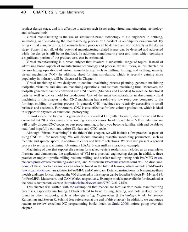
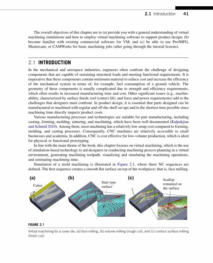
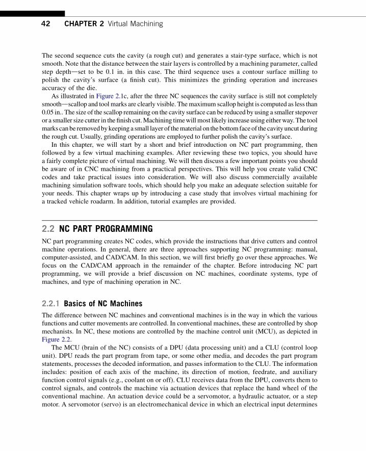
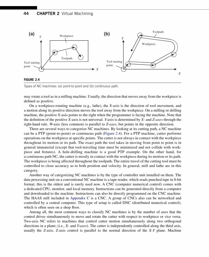
Tool startingpoint
Toolpath
Toolpath
Tool startingpoint
X
Y Workpiece (a) (b)
X
Y
Workpiece
FIGURE 24
Types of NC machines (a) point-to-point and (b) continuous path
44 CHAPTER 2 Virtual Machining
may rotate a tool as in a milling machine Usually the direction that moves away from the workpiece isdefined as positive
On a workpiece-rotating machine (eg lathe) the X-axis is the direction of tool movement anda motion along its positive direction moves the tool away from the workpiece On a milling or drillingmachine the positive X-axis points to the right when the programmer is facing the machine Note thatthe definition of the positive X-axis is not universal Y-axis is determined by X- and Z-axes through theright-hand rule W-axis (less common) is parallel to Z-axes but points in the opposite direction
There are several ways to categorize NC machines By looking at its cutting path a NC machinecan be a PTP (point-to-point) or continuous path (Figure 24) For a PTP machine cutter performsoperations on the workpiece at specific points The cutter is not always in contact with the workpiecethroughout its motion or its path The exact path the tool takes in moving from point to point is ingeneral immaterial (except that tool-traveling time must be minimized and not collide with work-piece and fixtures) A hole-drilling machine is a good PTP example On the other hand fora continuous path NC the cutter is mostly in contact with the workpiece during its motion or its pathThe workpiece is being affected throughout the toolpath The entire travel of the cutting tool must becontrolled to close accuracy as to both position and velocity In general mill and lathe are in thiscategory
Another way of categorizing NC machines is by the type of controller unit installed on them Thedata processing unit on a conventional NC machine is a tape reader which reads punched tape in 8-bitformat this is the oldest and is rarely used now A CNC (computer numerical control) comes witha dedicated CPU monitor and local memory Instructions can be generated directly from a computerand downloaded to the machine Instructions can also be directly programmed on the CNC machineThe HAAS mill included in Appendix C is a CNC A group of CNCs also can be networked andcontrolled by a central computer This type of setup is called DNC (distributed numerical control)which is often seen on a shop floor
Among all the most common ways to classify NC machines is by the number of axes that thecontrol drives simultaneously to move and rotate the cutter with respect to workpiece or vice versaTwo-axis NC refers to machines that control cutter motion simultaneously along two orthogonaldirections in a plane (ie X- and Y-axes) The cutter is independently controlled along the third axisusually the Z-axis Z-axis control is parallel to the normal direction of the X-Y plane Machine
(a) (b)
(c) (d)
FIGURE 25
CNC machines of 2 to 5 axes (a) water jet (Dix Metals wwwyoutubecomwatchvfrac14crgujRcyhhEampfeaturefrac14player_embedded) 2 axes (b) HAAS 3-axis CNC mill (c) 4th axis rotary table from Techno (d) gear cutting
using special 5-axis mill (wwwamtek-precisioncom)
22 NC Part Programming 45
supporting processes such as turning drilling punching and profiling belong to a two-axis NCIn addition a plasma cutter such as PlasmaCAM (see images at wwwplasmacamcomindexflaphp)and a waterjet (see youTube video wwwyoutubecomwatchv=crgujRcyhhEampfeature=player_embedded) are popular 2-axis NC machines
Three-axis motion is most common in many aspects The cutter is generally controlled in threeprincipal directions of the Cartesian coordinate system simultaneously A three-axis machine is able tocut not only pockets profiles and holes but also sculpture (or freeform) surfaces often seen in mold ordie manufacturing For example an ejector die shown in Figure 25b was machined using a HAAS3-axis mill
An add-on 4th axis rotary table can convert an existing 3-axis mill center into a full 4-axis CNCmachine The rotary table allows spindle access to the workpiece from various angles in one setup thatmight take several setups with a conventional 3-axis machine (as shown in Figure 25c)
A 5-axis CNC mill in general provides simultaneous motion control in three linear directions (X-Y- and Z-axes) and two rotations which usually are C (about Z-axis) and A (about X-axis) or C and B(about Y-axis) Such powerful machines support manufacturing a diverse range of components such asgear (Figure 25d) and turbine blades (see image at wwwthesurfacegrindercom) to varying degrees ofcomplexity and tolerances for high precision industries
46 CHAPTER 2 Virtual Machining
222 Basic Concept of Part Programming
NC part programming consists of planning and documenting the sequence of processing steps to beperformed on an NC machine The outcome is an NC program used to machine a desired part An NCprogram describes the sequence of actions of the controlled NC machine which include but are notlimited to the following
bull Tool movements including direction velocity and positioningbull Tool selection tool change tool offsets and tool compensationbull Spindle rotation direction and spindle rotation speedbull Cutting speed for different sequencesbull Application of cutting fluids
All actions must be specified in the NC program as a set of blocks (typically hundreds or thousands)A block is a group of words terminated by the end-of-block character (usually a carriage return CR)Figure 26 shows a sample block which performs a cut from current cutter location to Xfrac14 235 and Yfrac140475 along a straight line at a feedrate of 5 inmin In this sample block there are seven NC wordseach word consists of an alphabet address character (also called identifier) followed by a numericcharacter In the sample block N100 is simply a sequence number of the block G01 and G41 are NCwords that prepare cutter motion where G01 specifies a linear motion and G41 turns on cutter radiuscompensations from the left X235 and Y0475 specify the next cutter location F50 specifies thefeedrate andM07 is a miscellaneous function which turns a flood coolant on A list of sample identifiersand NC words are listed in Appendices A and B respectively at the end of this chapter
In general there are three methods for creating NC programs manual computer-assisted andCADCAM (Figure 27) All methods aim at creating NC codes also called machine control data ormachine code data Most MCD (or NC code) is common among NC machines Some codes may bemachine-dependent that is a same NC word could mean something very different from one to anotherCNC machine which presents a potential pitfall in NC programming The computer-assisted andCADCAM approaches (to be discussed in the next subsections) offer assistance from computer andsoftware tools in generating NC codes that alleviates the burden of coding by hand to some extentBoth approaches generate cutter location data (CL data) to be translated to MCD througha post-processor
Manual NC programming is the most straightforward The MCD can be directly programmed andentered into the CNC machine for simple cuts for example see profile milling in Figure 28 In this
NC Word(Sequence Number)
N100 G01 G41 X135 Y-0475 F50 M07
Dimension Words
MiscellaneousFunction
Address Character
Preparatory Functions
FIGURE 26
Sample NC block
FIGURE 28
A profile milling example (a) desired toolpath and (b) NC codes with explanations
FIGURE 27
Approaches of NC programming
22 NC Part Programming 47
sample of profile milling a cutter of 075 in diameter is cutting an 8 in 5 in 1 in aluminumworkpiece along a prescribed profile the following is a desired toolpath
bull Tool start position 001bull Move the cutter to ndash037501bull Spindle speed 2000 rpm feedrate 25 ipm
(a) (b)
Toolpath displayed on monitor for machining the part shown below
FIGURE 29
NC code verification using (a) CNCezPro (wwwcncezprocom) and (b) HAAS 3-axis mill (wwwhaascom)
48 CHAPTER 2 Virtual Machining
bull Plunge into workpiece 05 in deepbull Cut along outside of profile formed by P1 up to P8bull Retract to 637501 (next to P8)bull Move the cutter back to the start position
Although simple and straightforward manual programming at the MCD level is notnecessarily the best First it is often time consuming to figure out cutter locations based on partgeometry Usually a few predefined programs (canned cycles such as hole-drilling) comewith the CNC unit which makes manual part programming a little easier Second the MCDis limited in supporting complicated machining work (eg contour surface milling) inwhich cutter locations on the surface must be accurately identified Third although MCDcommands and formats are fairly well standardized differences do exist between machinemanufactures As a result an NC part program that works on one machine may not work onanother one
It is critical that the MCD be verified before conducting actual cutting This can be done by eitherusing a third-party NC software tool such as CNCezPro (Figure 29a) or on the monitor screen of theCNC machine (eg HAAS 3-axis mill shown in Figure 29b)
223 Computer-Assisted Part Programming
Computer-assisted part programming methods are faster and more reliable than manual program-ming techniques There are a variety of forms of them The common feature of these programs is thatthe part and machining paths are not defined directly with G-code but through English-like state-ments or through interactive graphic instructions It consists of a series of English-like geometry andmotion statements which are used to define the workpiece and machine toolpath A widely usedlanguage is Automatically Programmed Tools (APT) and its variations Its instructions can becompiled and converted into G-code programs Readers may refer to Chang et al (1998) fora detailed discussion of APT
22 NC Part Programming 49
APT uses language statements to define part shape and tool motion as well as machine tool-dependent data (eg feedrates and spindle speeds) The general procedures of generating APTsource codes involve the following steps
1 Identify part geometry2 Identify cutter motions feeds speeds and cutter parameters3 Code the geometry cutter motions and general machine instructions into the part programming
languages The code is known as source4 Compile or process the source to produce the machine-independent list of cutter movements and
auxiliary machine control information known as the cutter location data file (or CL data)5 An APT processor program is used to read these statements interpret the meanings and perform all
the necessary calculations to generate a series of cutter location points that define the toolpath Thegeneralized APT output (usually in CL data) is converted to the particular format G-code requiredby the CNC machine using a post-processor program
6 The CL data file contains (mainly) details of cutter moves either as a series of absolute linearGOTO moves or relative GODLTA moves Note that the CL data is different from APT The CLdata is defined by the International Organization for Standardization (ISO)
7 Postprocess the CL Data to produce MCD for the particular target CNC machine8 Transmit the MCD to CNC machine and verify it
A major advantage of APT is that it has developed into an accepted standard for machine tools inaddition to alleviating the burden of coding at the very basic level A prime disadvantage of APT is thatit uses English-like commands to define geometry instead of the much more convenient graphicalmethods Note that the APT-type programming approach is being gradually replaced by the moreadvanced CADCAM approach
(a)
PARTNOEXAMPLEMACHINMILL5CUTTER075P0 = POINTndash1ndash10P1 = POINT000P2 = POINT00200P3 = POINT20200P4 = POINT20400P5 = POINT40400P6 = POINT40200P7 = POINT60200P8 = POINT6000L1 = LINEP1 P2L2 = LINEP2 P3L3 = LINEP3 P4L4 = LINEP4 P5L5 = LINEP5 P6L6 = LINEP6 P7L7 = LINEP7 P8L8 = LINEP8 P1
PL1 = PLANE00ndash05600ndash05 020ndash05SPINDL2000FEDRAT25COOLNTONFROMP0GOTO L1 TO PL1 ON L8GOLFT L1 PAST L2GORGT L2 TO L3GOLFT L3 PAST L4GORGT L4 PAST L5GORGT L5 TO L6GOLFT L6 PAST L7GORGT L7 PAST L8GORGT L8 PAST L1RAPIDGOTO P0COOLNTOFFENDFINI
(b)
FIGURE 210
The profile milling exampledAPTapproach (a) desired toolpath and geometry entities identified and labeled and
(b) APT source codes
50 CHAPTER 2 Virtual Machining
The same profile milling discussed earlier is employed as an example to illustrate APTprogramming As shown in Figure 210a the geometry of the contour profile is identified and labeledas points (P0 to P8) and line segments (L1 to L8) These are specified in the APT codes shown inFigure 210b The motion statements which describe the toolpath in relation to the part geometry aregiven in the codes such as GOTO GOLFT (toolpath to the left of the part) and GORGT RAPID
(a) (b)
O0100 (1) (010903-193923) N0010T1M06 S2000M03 G00X-375Y0 G43Z1H01M08 G01Z-5F25 Y2 G02X0Y2375I375J0 G01X1625 Y4 G02X2Y4375I375J0 G01X4 G02X4375Y4I0J-375 G01Y2375 X6 G02X6375Y2I0J-375 G01Y0 Z1 G00X-375 M30
PARTNO PLATE MACHIN UNCX01 1 UNITS INCHES LOADTL 1 SPINDL RPM 2000000000 CLW COOLNT FLOOD RAPID GOTO -03750000000 00000000000 10000000000 FEDRAT 2500000 IPM GOTO -03750000000 00000000000 -05000000000 GOTO -03750000000 20000000000 -05000000000 CIRCLE 00000000000 20000000000 -05000000000 $ 00000000000 00000000000 -10000000000 03750000000 GOTO 00000000000 23750000000 -05000000000 GOTO 16250000000 23750000000 -05000000000 GOTO 16250000000 40000000000 -05000000000 CIRCLE 20000000000 40000000000 -05000000000 $ 00000000000 00000000000 -10000000000 03750000000 GOTO 20000000000 43750000000 -05000000000 GOTO 40000000000 43750000000 -05000000000 CIRCLE 40000000000 40000000000 -05000000000 $ 00000000000 00000000000 -10000000000 03750000000 GOTO 43750000000 40000000000 -05000000000 GOTO 43750000000 23750000000 -05000000000 GOTO 60000000000 23750000000 -05000000000 CIRCLE 60000000000 20000000000 -05000000000 $ 00000000000 00000000000 -10000000000 03750000000 GOTO 63750000000 20000000000 -05000000000 GOTO 63750000000 00000000000 -05000000000 GOTO 63750000000 00000000000 10000000000 RAPID GOTO -03750000000 00000000000 10000000000 COOLNT OFF SPINDL OFF FINI
(c) (d)
CS0X
X
y
y
CS0CS1
CS1
CutterWorkpiece
Toolpath
Cutter
x x
yy
zz
FIGURE 211
The profile milling exampledCADCAM approach (a) solid models and toolpath (b) milling simulation (c) CL
data file and (d) MCD (or tap file)
23 Virtual Machining Simulations 51
(rapid retract) Auxiliary statements such as COOLNT ON (turn on coolant) FEDRAT (feedrate)SPINDL (spindle speed) are also specified
224 CADCAM Approach
The CADCAM approach is the most popular and advanced approach in generating CNC codes Theprocess starts with creating a reference (or design) model and workpiece and then assembling them inassembly mode For example the design model and workpiece of the profile milling discussed beforeare assembled as shown in Figure 211a
After the solid models are assembled users define manufacturing set up including choosinga workcell (eg a 3-axis mill) and coordinate system (or machine zero) Then users createa machining sequence (eg a profile-milling sequence) In the meantime users choose a cutter andspecify machining parameters (eg federate spindle speed) At this point a machining sequence iscompletely defined CADCAMwill generate a toolpath like that shown Figure 211a the toolpath wascreated using ProMFG for this example
The profile-milling sequence can also be simulated (eg in Vericut shown in Figure 211b) Notethat Vericut (wwwcgtechcom) is a third-party software that is integrated to ProMFG for CNCsimulation and G-code verification In addition the toolpath generated can be output as a CL data fileas shown in Figure 211c The CL data can be converted to MCD using a proper post-processor thatsupports CNC machines at shop floor As an example the MCD shown in Figure 211d is post-processed for a HAAS CNC mill which is also called a tap file
In the rest of the chapter we will focus on the CADCAM approach from a broader aspectdthat isvirtual machining simulations in support of product design
23 VIRTUAL MACHINING SIMULATIONSA typical process of conducting a virtual machining simulation using CADCAM tools involvescreating a design model (perfectly finished part) creating workpiece (a raw stock for machining)choosing manufacturing set up defining machining sequences generating toolpath checking theresults and postprocessing the toolpath for CNC codes as shown in Figure 212a
The manufacturing set up involves choosing a machine (eg a 3-axis mill) and defininga machining coordinate system (also called machine zero) usually on the front left corner of the topsurface of the workpiece for the NC sequence The definition of a NC sequence includes selecting thetool and retract plane (the plane to which the tool retracts after a cut) and defining machiningparameters (eg feedrate spindle speed) After a complete sequence is defined the toolpath can begenerated in the form of CL data Machining toolpath (Figure 212c) machining simulation(Figure 212b) and important machining sequence information such as machining time are generatedby the CADCAM software In addition a post-processor can be chosen to generate MCD (machinecontrol data)dM-codes and G-codes for a particular type of CNC machinedfrom the CL data
In the following we will use examples to illustrate the process of conducting virtual machiningincluding milling and turning operations We will focus more on milling and just mention turningbriefly This is because NC programming for turning sequences is often carried out manually since theX- and Z-coordinates of the cutter locations can be more easily acquired Creating NC codes through
(c)
Post-Processing
Create Design Model
Create Workpiece
Define Manufacturing Setup
Define Machining Sequences
Generate the Toolpath
Check Results
(d)
Workpiece
Drive Surface
Tool Containment Rectangle
(a) (b)
FIGURE 212
Virtual machining (a) a typical process (b) design model with workpiece (c) machining toolpath and
(d) machining simulation
52 CHAPTER 2 Virtual Machining
virtual machining is sometimes overkill However from a design perspective it is essential thatdesigners incorporate all NC operations when addressing manufacturability of the product includingdetecting potential manufacturing-related issues and coming up with an overall machining timeestimate for design trade-off if necessary
231 Basic Machining Simulations
Basic machining operations refer to milling sequences involving simple geometric features such asprofile milling hole-making pocket milling and so on These basic sequences can be performed usinga standard 3-axis mill
For a full-scale CADCAM system such as ProMFG or CAMWorks users will have to create 3Dsolid parts for the design model (and usually workpiece as well) in order to proceed For software toolsof CAM emphasis such as Mastercam a simple 2D wireframe is often sufficient to support basicmachining operations In this section we will use a simple example shown in Figure 213a to discussnumerous aspects of the basic machining operations This example involves profile milling pocketmilling and hole-making Figure 213b shows the toolpaths of the three NC sequences
Using a CAM software such as Mastercam a 2D wireframe that describes the geometry of theouter profile pocket and holes (Figure 213a) is sufficient for carrying out a virtual machiningoperation The size of the design model is 6 in 4 in Both corner radius and diameter of the four holesare frac34 in The radii of the large and small semicircles of the center pocket are 1 in and frac12 in
Profile (Blue)
Pocket (Blue)
Hole Drilling (Green)
Workpiece (Dotted)
(a) (b)
FIGURE 213
Basic machining sequences (a) machining simulation and (b) machining toolpaths
Design model (2D wireframe)
Workpiece (Dotted line)
Pocket (Blue)
(a) (b)
FIGURE 214
Basic machining example (a) 2D wireframe design model and (b) with workpiece in isoview
23 Virtual Machining Simulations 53
respectively A rectangular block of 6 in 4 in 075 in is added to the wireframe as a workpiece asshown in Figure 213b Note that the straight lines and the circular arcs in Figure 214a are created byentering end point locations center point locations radius and so on instead of creating solid featuresas those of CAD tools While entering the point locations a coordinate system was referred to Thiscoordinate system is implicitly defined as the reference so called the machine zero to which all CLdata of the toolpath refer
An end mill of 11 in diameter is chosen for the first NC sequence which is a profile milling (calledcontour milling in Mastercam) Some software (eg Mastercam) provides a detailed view on thegeometry of the cutter such as the one shown in Figure 215a Other software (eg ProMFG) requiresusers to enter basic parametersdfor instance cutter diameter and lengthdto define a cutter Ingeneral a cutter is represented as a cylinder in machining simulation for visual for example see thecutter of Mastercam shown in Figure 215b Note that Mastercam provides a predefined cutter library(Figure 215c) which helps users pick suitable cutters for machining In practice one will have to
FIGURE 215
Selecting a cutter (a) detailed geometry of an end mill in Mastercam (b) cutter in virtual machining simulation
and (c) prescribed tool library in Mastercam
54 CHAPTER 2 Virtual Machining
check the mechanist at the shop floor to ensure that the cutters selected for virtual machining corre-spond to those on the tool turret in the CNC machine
Several important cutting parameters are required for conducting profile milling In this examplethe (overall) depth of cut required for the profile milling is set to frac12 in Recall that the thickness of theworkpiece is frac34 in Therefore there will be a layer of frac14 in material intentionally left uncut aftercompletion of the profile pass The maximum step depth which defines how thick the cutter trimsaround the workpiece in one pass is set to frac14 in in this example Note that step depth is highly relatedto the size of the cutter among other factors In general a cutter of larger diameter has more strength toplunge deeper into the workpiece A cutter of stronger material (eg cutter of carbide inserts) allowsfor a larger step depth The rule of thumb is that the step depth has to be less than the radius of thecutter Since the (overall) depth of cut is frac12 in and the maximum step depth is frac14 in it will take twopasses for the cutter to go around the workpiece to complete the profile milling
Note that the extra stepsdlead in and lead out respectivelydwhen the cutter approaches andleaves the workpiece are often added to the profile toolpath as shown in Figure 216a Once thetoolpath is generated machining simulation can be shown like that of Figure 216b in for exampleMastercam
One practical issue that must be taken into consideration for profile milling is mounting theworkpiece to the workbench of a CNC machine Notice that in some cases the cutter may not be ableto cut a complete path around the workpiece without colliding with the clamps that hold the workpieceClamping and fixtures is an important issue in practice which will be discussed in Section 24
The second NC sequence is pocket milling For a pocket milling the cutter first plunges into theworkpiece then moves around to make a cut The cutter usually moves in one direction steps sidewayand cuts in the reverse direction The cutting pattern is similar to mowing the lawn in your backyardwhere we step sideways at the end of each pass before reversing the mowing direction This is one of
Toolpath
Lead In
Lead Out
(a) (b)
FIGURE 216
Profile milling sequence (a) toolpath and (b) milling simulation
Profile pass(a) (b) (c)
FIGURE 217
Pocket milling sequence (a) toolpath (b) milling simulation and (c) profile cut
23 Virtual Machining Simulations 55
the available scan patterns in CAM called zigzag Other scan patterns include spiral among otherswhere the cutter starts roughly from the center of the pocket and follows a spiral-like path andgradually moves outward
The amount of step sideways is called stepover It is obvious that stepover has to be less than thecutter diameter in order to make a clean cut As a rule of thumb the stepover is usually less than 80of the cutter diameter in practice After performing the scan passes another profile pass is added tomove the cutter around the wall of inner pocket boundary to clean up the remaining material along theboundary as shown in Figure 217a In this example the cutter chosen is a ⅜ in end mill in which thestep depth chosen is 16 in If we are cutting a frac12 in deep pocket it will take eight sets of complete scanand profile passes each 16 in deep to complete the pocket milling
Also in order to ensure a smooth inner pocket boundary it is a good practice to leave a thinmaterial layer around the boundary wall of the pocket and add a profile cut at the end to ensurea smoother pocket boundary similar to that of Figure 217c
The third NC sequence is hole-making There are four blind holes offrac34 in diameter at the cornersCreating virtual machining for hole-making is straightforward It is obvious that the drill you pick must
FIGURE 218
Hole-making NC sequence (a) detailed geometry of a drill in Mastercam and (b) toolpath
56 CHAPTER 2 Virtual Machining
have the same diameter as those holes or a drill of slightly smaller size with a follow-on boring orreaming operations In this case afrac34 in drill (Figure 218a) is chosen The toolpath generated is shownin Figure 218b
All three NC sequences can be easily combineddtoolpath and machining simulations can be likethose shown in Figures 213a and 213b respectively In addition the toolpath can be converted intoG-codes and M-codes as discussed earlier
232 Advanced Machining Simulations
Geometrically complex parts are commonly found in the automotive and aerospace industrieswhere molds and dies are manufactured for production The time spent to manufacture molds ordies of different sizes and complexities ranges from 1200 to 3800 hours (Sarma and Dutta 1997)Considerable time (49ndash72) is spent in contour surface milling for the design surfaces (thesurfaces to be machined) of molds and die Design changes in structural geometry due tofunctional considerations may affect manufacturing cost significantly and vice versa Amongdifferent types of machining operations contour surface milling is the most critical for mold anddie machining since surface milling directly affects the quality and accuracy of the designsurface
In practice a machining operation of a die or mold or any parts with sculpture (or freeform)surfaces involves four machining sequences First a face milling will clean up the mating surface forthe die Second sequence is usually a volume milling that removes material in the cavity at a fast speedOften a relatively large cutter is employed with a higher feedrate to remove material as fast as possiblewithout regard to surface finish Next is a local milling which is essentially a smaller-scale volumemilling that removes the remaining small chunk of material left from the previous volume millingsequence In general a smaller cutter is employed for local milling The last NC sequence is contoursurface millingda finish cut this is considered the most important machining sequence for sculpturesurfaces since the scallop height of the uncut material remaining on the machined surface determines
23 Virtual Machining Simulations 57
the surface quality of the machined part In addition a common practice suggests a small layer of stockshould remain on the surface of the cavity from volume milling and local milling in order to eliminatetool marks
Existing commercial virtual machining tools such as ProMFG CAMWorks and Mastercamsupport contour surface milling using various methods (eg isoparametric constant curvature andconstant scallop height) In this section we will assume ProMFG for machining a part of a 16 in 10 in 4 in block with a sculpture surface as shown in Figure 219a Note that the sculpture surfaceis lofted using four section sketches of respective circular arcs (Figure 219b) For this example wewill include a volume milling and a local milling assuming a 3-axis mill We will include a 5-axiscontour surface milling for finish cut The workpiece is a 16 in 10 in 4 in block Thecoordinate system CS0 at the top left corner of the workpiece as shown in Figure 219c is chosen asthe machine zero for this model
Two cutters are chosen for this example A 1 in end mill with corner radius frac14 in (Figure 220a) isselected for volume milling (ie the rough cut) Note that such a cutter is often referred to as bull millSeveral such cutters are commercially available for example a four- and two-flutes end mills is shownin Figure 220a Note that the sharp corner of an end mill is its weakest point The corner radius designof a bull mill strengthens the end mill by reducing chipping and providing longer tool life In mold
Machine zero
x
zCS0
(b)(a)
(c)
R650
R340
R684
400
1000
R803
FIGURE 219
Sculpture surface (a) solid model (b) section sketches and (c) with workpiece and machine zero
FIGURE 220
Cutters chosen for the machining operation (a) 1 in end mill with corner radius and (b) frac12 in ball cutter
FIGURE 221
Volume milling NC sequence (a) isoview and (b) end view
58 CHAPTER 2 Virtual Machining
applications both end and bull mill cutters have traditionally been used In addition to the bull milla frac12 in ball nose cutter (Figure 220b) is employed for both local milling and contour surface millingNote that a ball nose cutter tends to leave less tool marks on the machined surface thus leading toa better surface finish
For the volume milling the step depth and stepover are 05 in and 09 in respectively The scanpattern is back and forth along the longitudinal direction (x-axis of CS0) The resulting machinedsurface is shown in Figure 221 in which material remains on the surface and requires a following NCsequence for further clean up The machining time estimated by ProMFG is 37 minutes assuminga feedrate of 20 inmin Determining an adequate feedrate for a machining sequence is critical inpractice A fast feedrate will reduce overall machining time however it is subject to a possible roughsurface finish and a higher probability of cutter breakage and shorter tool life Feedrate will be dis-cussed in more detail in Section 24
FIGURE 222
Machined surface after the local milling sequence (a) ball nose cutter with stepover 04 in and step depth
02 in (b) end mill of corner radius 01 in with stepover 04 in and step depth 02 in and (c) end mill of
corner radius 01 in with stepover 04 in and step depth 005 in
23 Virtual Machining Simulations 59
For the local milling the step depth and stepover are 02 in and 04 in respectively Both aresmaller than those of volume milling This is mainly because a smaller cutter is employed Alsoa smaller feedrate 5 inmin is chosen for this sequence The scan pattern is spiral which is deter-mined by ProMFG The resulting machined surface is shown in Figure 222a in which surface issmoother but still requires further clean up and polish The machining time for the local milling isestimated by ProMFG as 137 minutes partly due to a smaller feedrate
The machined surface is certainly not acceptable for practical applications Before carrying outa contour surface milling is there any way to improve the quality of the machined surface Is thecurrent setup for local milling the best There are several possibilities that may provide a better resultFirst an end mill of the same diameter (frac12 in) but a smaller corner radius 01 in (vs frac14 in) requiresabout the same machining time Comparing with the first case shown in Figure 222a this bull millprovides a machined surface with a slightly better surfacedespecially in the area closer to the centerof the spiral pattern (Figure 222b) This is mainly due to the smaller surface curvature closer to thecenter of the spiral pattern in which a bull mill leaves less material than that of a ball nose cutter
How about step depth and stepover Which parameter will impact more to the surface quality Ingeneral it depends on the geometric shape of the design surface For a surface of high curvature
60 CHAPTER 2 Virtual Machining
a smaller step depth reduces the staircase type surface For a surface of small curvature one can affordto choose a larger stepover to reduce the machining time and yet lead to a relatively good surfacefinish Smaller stepover and smaller step depth will certainly give a better surface finish however itmay require substantially more machining time to complete the cut For example Figure 222c showsa much smoother machined surface created by using a smaller step depth 005 in in which themachining time jumps to more than 600 minutes assuming the same feedrate Note that in practiceone may increase the feedrate when a smaller stepover and step depth are employed resulting ina reduced machining time
Although surface quality is much improved spending 600 minutes for a local milling is probablytoo much Plus we will employ a contour surface milling to perform the finish cut which serves thepurpose of polishing the surface For this example we will stay with the first case (surface finish shownin Figure 222a) after completing the local milling sequence
The third NC sequence is contour surface milling for a finish cut using a 5-axis mill A step size of04 in and the same feedrate 5 inmin are chosen for this sequence As mentioned earlier there areseveral options in generating a toolpath for the contour surface milling We choose the surface isolineoption for toolpath generation where one parametric coordinate of the surface is fixed at prescribedvalues in order to generate cutter contact curves that stay right on the surface (Figure 223a) Note thatthe space between neighboring tool passes is in general less than the stepover specified More on the
Cutter
CS0x
y
CS0
r
r
Tool mark
Tool mark
(a) (b)
(c) (d)
FIGURE 223
Contour surface milling (a) toolpath for stepover 04 in (b) machined surface with stepover 04 in tool mark
visible (c) machined surface with stepover 02 in tool mark still visible and (d) machined surface with stepover
04 in and 005 in stock allowed tool mark removed
23 Virtual Machining Simulations 61
isoline option and toolpath generation will be discussed in Chapter 3 The machining time for thiscontour surface milling is estimated as 85 minutes based on a feedrate of 5 inmin Note that inpractice a higher feedrate is often employed for the final finish cut since the material remaining thesurface is usually minimum
The resulting surface by combining all three NC sequences can be seen in Figure 223b There areclear tool marks on the machined surface These marks were left from the previous sequencesmainly from the rough volume milling There are two ways to remove or minimize the tool marksFirst one may reduce the stepover for the contour surface milling A smaller stepover will lead toa surface with smaller scallop height therefore a better surface quality with less visible tool marks(Figure 223c) in which the stepover is reduced to 02 in However the machining time increasesabout twice (increased from 85 to 160 minutes) We will discuss more on the calculations of thescallop height in Chapter 3
Another approach and a better one is to specify a small layer of stock material uncut (stockallowed) while performing volume and local milling sequences The layer thickness should be slightlylarger than the desirable scallop height If such a stock material is specified in previous sequences toolmarks should be completely removed in theory With a stock material of 005 in and a smaller stepover(02 in) the machined surface does not reveal any tool marks as can be seen in Figure 223d
If combining all three NC sequences the overall machining time is about 334 minutes (37thorn 137thorn160) which is considered very good for machining such a sculpture surface
233 Turning Simulations
Part programming for turning is much simpler than that of milling This is mainly because that NCcode for turning only requires X- and Z-locations of the cutter A cutter for a turning operation onlymoves on the X-Z plane often following straight paths For example an area turning sequence thatremoves the material on the outside cylindrical and front end surfaces of a cylindrical block is shown inFigure 224 Note that when translating the toolpath to NC codes special attention may be required Ifyou are converting a toolpath created in ProMFG to HAAS CNC lathe there are several modificationsandor extra steps that need to be carried out For example the CL data output for the G02 and G03commands (circular interpolation) must use ldquoRrdquo values for radius If ldquoIrdquo or ldquoKrdquo values are presenta setting for the post-processor will need to be altered in order to force the output with ldquoRrdquo valuesAlso while selecting UNCL01P11 to postprocess the CL data for HAAS lathe this post-processordoes not output the X Z R (R is the radius of circular interpolation in G02 and G03) In additionthe post-processor does not output the F (feedrate) values with a decimal point which is required bythe HAAS controller Again a setting for the post-processor will need to be altered to output CNCcodes with correct format
Going over all the modeling and simulation work for a simple turning cut such as the areaturning shown in Figure 224b may not be the best option in terms of time and effort Plus thereare additional setups in the NC postprocess that are usually required for valid NC codes Thereforemanual coding is often more effective for the CNC lathe Even when machining a sculpture surfaceon turning operation a toolpath can be defined along a planar curve which is much easier to obtainmanually than that of milling often dealing with a surface As a result part programming forturning operations is usually carried out by collecting cutter location data on the X-Z plane andmanually composing NC programs
FIGURE 224
Area turning (a) material to be removed on the cylindrical and front end surfaces (b) turning toolpath and
(c) machined surface
62 CHAPTER 2 Virtual Machining
24 PRACTICAL ASPECTS IN CNC MACHININGSo far our discussion has been focused on virtual machiningdeverything is carried out in a virtualenvironment In a virtual environment almost anything can be set up and simulated Machiningsequences that look good on a computer do not guarantee they can be implemented physicallywithout any flaws For example a deep and narrow pocket may not be possible to cut since a smallsize cutter is usually short and will not be able to reach deep enough to the bottom of the pocketAlso for profile milling in a virtual environment a cutter moves around the outer boundary of theworkpiece without any problem In reality the workpiece must be clamped to the workbench of theCNC machine and cutter must not collide with the clamps What kind of clamp or fixture is suitablefor mounting the workpiece for a profile milling sequence
When a fixture is employed to mount the workpiece will the cutter run into the fixture Also howdoes one determine appropriate feedrate and spindle speed Which kind of cutters are suitable fora given workpiece material using selected NC sequences Most of such issues have been welladdressed in NC workbooks or machinist handbooks (eg Oberg et al 2012) We will discuss some ofthe common practical issues you may encounter in NC machining The goal of this section is toprovide you with some practical aspects in applying virtual machining to practical NC operations
24 Practical Aspects in CNC Machining 63
There are several principles you may want to consider while designing a part to be machined Theseprinciples usually lead to a part design that can bemachinedwith fewer problems First designers shouldconsider designing parts that can be made out of standard size material stock This will minimize theneed to go through additional machining sequences that cut a standard stock to the desired size Secondavoid deep pockets in parts you may not find a cutter long enough to reach the bottom of the pocketEven if you can the long cutter may deflect or break during deep pocket cutting Third keep all filletradii identical whenever possible and keep them larger than the radius of available cutters A large cutterwill not be able to cut a small fillet Fourth keep all hole sizes identical if possible and avoid odd-sizeholes As a result one or two drills are able to make all holes which minimizes the frequency for toolchange Hole sizes should in general match those of available drills Finally avoid having to cut the partfrom multiple sides if possible Certainly compromises will always have to be made when designinga new part with machining considerations However staying with the preceding principles as much aspossible will make the machining sequences more straightforward and usually less costly
In the following we will discuss three main issues (1) choice of jigs and fixtures (2) determinationof machining parameters including feedrate and spindle speed as well as cutter selection and (3)setting up NC machining In Appendix C we will use a HAAS mini-mill as an example to go overa few important steps in setting up a NC machining operation on a shop floor
241 Jigs and Fixtures
Mounting the stock material to the workbench (also called feed table) is often the most critical andtime-consuming element of part machining The stock material must be mounted in a way that all thetools are able to complete their paths without interfering with a fixture or the stock coming loose ormoving
The easiest way tomount stock is in a vise (Figure 225a) Once the vise is aligned andmounted to theworkbench the coordinate system for the part can easily be identified (more about this inAppendixC) Forcutting circular parts or placing bolt patterns at the end of shafts a self-centering 3-jaw chuck(Figure 225b) will save time Flat plate or sheet material can be clamped using the standard block anda clamp set can be used to fix generic parts to the table (Figure 225c)
When machining odd-shaped parts special jigs may have to be made It is important to be patient infastening the stock to the workbench The followings are a few examples that are employed to mountthe workpiece
(a) (b) (c)
FIGURE 225
Common jigs and fixtures (a) machinists vise (b) self-centering 3-jaw chuck and (c) block and clamp setup
(a) (b) (c)
FIGURE 226
Milling machine vise (a) plain vise (b) swivel base and (c) swivel base with vise
64 CHAPTER 2 Virtual Machining
The milling machine vise shown in Figure 226 is the most common type of workpiece-holdingdevice used on the milling machine The plain milling machine vise is used for holding a work-piece that has parallel sides The vise is bolted directly to the table using the T-slots in the machinetable (Figure 226a) The plain vise can be accompanied by a swivel base The swivel base(Figure 226b) is graduated in degrees and allows the vise to swivel in the horizontal plane The swivelbase gives the vise a greater degree of versatility (Figure 226c) but should be avoided when doingheavy rough-cutting operations because it reduces the rigidity of the setup
242 Cutters and Machining Parameters
The choice on cutters and workpiece material largely determine feedrate and spindle speed Cutters canbe grouped in two major categories high-speed steel (HSS) and carbide inserts as shown in Figure 227HSS cutters maintain hardness and strength at elevated temperature and are less expensive Two basictypes of HSS cutters are commercially available M-series (Molybdenum type) and T series (Tungstentype) M-series steels contain up to 10 molybdenum with chromium vanadium tungsten and cobaltT-series steels contain 12 to 18 tungsten with chromium vanadium and cobalt
M-series steels have generally higher abrasion resistance than T-series less distortion in heattreatment and are less expensive Carbide inserts endure high temperatures with high strength and
FIGURE 227
Cutters (a) HSS cutters and (b) carbide insert
Flat endmilld=cutter diameter
Axis of revolution
d
(a) (b)
Ball Nose CutterIf ball is not ldquoburiedrdquo in workpiece then a will be less than cutter diameter ie no cutting occurs at full tool diameter
Cutter Axis
a
Cutting edge
FIGURE 228
Cutters (a) flat endmill and (b) ball nose cutter
24 Practical Aspects in CNC Machining 65
hardness especially suitable for high-speed cutting The tungsten carbide (WC) cuts nonferrousabrasive materials and cast irons Titanium carbide (TiC) has higher wear resistance thanWC but is notas tough Titanium carbide cuts hard materials mainly steels and cast irons
From their geometric shape there are flat endmill (Figure 228a) ball nose cutter (Figure 228b)and bull mill (Figure 220a) In general endmills are suitable for face profile and pocket milling Aball nose cutter is more suitable for sculptural surface milling since there is less tendency to gougeusing a ball nose cutter
Two of the most critical machining parameters are spindle speed and feedrate Spindle speed N(rpm) is usually determined by the cutting speed V (inmin) that is
N frac14 V=ethpdTHORN (21)
where d is the cutter diameter (in) In general factors affecting the calculation of cutting speed include(1) the material being machined (steel brass tool steel plastic wood) (2) the material the cutter ismade from (carbon steel high-speed steel carbide ceramics) and (3) the economical life of the cutterthat is the cost to regrind or purchase new compared to the quantity of parts produced
You may find recommended cutting speeds in machining textbooks or handbooks for examplessee Tables 21a and 21b As shown in the tables cutting speed is provided in a large range This isbecause there are other factors to consider while determining cutting speed (eg type of the millingsequences) A rough cut usually requires a larger cutting speed thus a higher spindle speed in order toremove material fast Different data sources may offer cutting speeds that differ by sometimessignificant amounts Numbers obtained from machining handbooks are a good starting point You mayhave to make needed adjustments onsite
Once an adequate spindle speed is determined a feedrate f (inmin) can be calculated using thefollowing equation
f frac14 ft N n (22)
where n is the number of teeth on the cutter and ft is the feed per tooth (in) as depicted in Figure 229Factors that affect the feedrate include (1) type of tool (eg a small drill vs a large end mill) (2)surface finish desired (3) power available at the spindle (to prevent stalling of the cutter or workpiece)
Table 21 Recommended Cutting Speeds
(a) Recommended by Kalpakjian and Schmid (2010)
Workpiece Material
Cutting Speed (ms)
HSS Carbide Inserts
Aluminum Alloys 15 w 6 10 thornMagnesium Alloys 3 w 5 12 thornCopper Alloys 03 w 15 15 w 7
Steels 01 w 07 05 w 4
Stainless Steels 02 w 1 1 w 2
High-Temp Alloys 005 w 01 02 w 03
Titanium Alloys 01 w 1 05 w 2
Cast Irons 02 w 06 05 w 2
(b) Recommended by Krar et al (2010)
Workpiece Material
Cutting Speed (mmin)
HSS Carbide Inserts
Machine Steel 21 w 30 45 w 75
Tool Steel 18 w 20 40 w 60
Cast Iron 15 w 25 40 w 60
Bronze 20 w 35 60 w 120
Aluminum 150 w 300 300 w 600
ftV
Rack angle
Relief angle
FIGURE 229
Feed per tooth
66 CHAPTER 2 Virtual Machining
(4) rigidity of the machine and tooling setup (ability to withstand vibration or chatter) (5) strength ofthe workpiece (high feedrates will collapse thin-wall tubing) and (6) characteristics of the materialbeing cut (eg chip flow depends on material type and feedrate)
The recommended feed per tooth for high-speed steel and carbide inserts are listed in Table 22aand 22b respectively As shown higher feed per tooth is recommended for carbide insert cutters whilecutting hard materials such as steels Also higher feed per tooth is recommended for face milling thanend milling This is because more teeth are in contact with the workpiece in face milling thus a higher
Table 22 Recommended Feed per Tooth by Krar et al (2010)
(a) High-speed steel
Workpiece Material
Face Mills End Mills
in mm in mm
Aluminum 0002 055 0011 028
Brass and bronze 0014 035 0007 018
Cast Iron 0013 033 0007 018
Bronze 0012 030 0006 015
Tool steel 0010 025 0005 013
Stainless steel 0006 015 0003 008
(b) Carbide inserts
Workpiece Material
Face Mills End Mills
in mm in mm
Aluminum 0020 050 0010 025
Brass and bronze 0012 030 0006 015
Cast Iron 0016 040 0008 020
Bronze 0012 040 0008 020
Tool steel 0014 035 0007 018
Stainless steel 0010 025 0005 013
24 Practical Aspects in CNC Machining 67
feedrate While carrying out finish cut the feedrate can be turned up if material remaining is minimalAgain numbers obtained from machining handbooks only provide a good starting point
243 Setting a CNC Sequence
In this subsection wewill go over a few important points in setting up an NCmachining sequence at theshop floor These are the things that one must be aware of when anNC program is generated and is readyto carry out the machining sequence using a CNC machine Since there are wide varieties of machineswewill only discuss two key stepswithout referring to specificmachines The goal here is to provide youwith some ideas when bringing the part program to a CNCmill and to serve as a reminder that there arepractical issues to go over before a successful machining sequence can be carried out on the shop floorWe use aHAASmini-mill as an example to illustratemore detailed procedures and setups inAppendixCfor those who are interested in learning more or those who have access to a HAAS mill
After a workpiece is loaded and secured on the workbench two key steps are followed loading andsetting up tools and setting up work coordinate and machine zero
Loading cutters is one of the most important steps in setting a CNC machining sequence You maycollect all the needed cutters and follow the machine instructions to load them to the mill Once alltools are loaded into the tool changer the lengths of each must be measured You will also need tomeasure cutter diameters if tool radius compensations are included in your NC codes Before
FIGURE 230
Using edge finder to set up X-axis
68 CHAPTER 2 Virtual Machining
measuring lengths we first place a work coordinate (or machine zero) on the stock material in the sameplace that you have set it in CAM software (such as ProMFG or Mastercam) Machine zero is usuallyplaced at the front left corner of the top surface of the stock Usually we load a drill chuck with an edgefinding tool (Figure 230) into the spindle move the edge finder to the X position of the part using thejog handle and zero the X-axis We repeat the similar steps for setting up Y-axis
The Z-axis will be set after all the tools needed for machining are loaded Often the first cutter isadvanced into the spindle Then we position the tool tip over the top of the X and Y-zero We lower thetool and place a feeler gage (Figure 231) to set zero for Z-axis Since the Z axis is zeroed using the first
FIGURE 231
Z-axis offset and tool length offset
25 Commercial Machining Simulation Software 69
tool the length offset for tool one should be zero The thickness of the feeler gage must now besubtracted from the Z axis height The same steps will have to be repeated to measure or offset the toollengths for all cutters loaded
Once these two steps are completed you are ready to load the program to the machine Usuallya CNC mill is networked with a PC In that case an NC program can be loaded to the mill very easilyOnce a program is loaded it usually automatically becomes the selected program the mill will run It isa good practice to verify the toolpath on the monitor screen of the mill like that shown in Figure 29bbefore running the program
25 COMMERCIAL MACHINING SIMULATION SOFTWAREA large number of commercial CAM software tools can currently be obtained There is general-purpose CAM software that supports turning and milling sequences There are also special-purposecodes that focus on narrow tasks (eg software for creating a toolpath only for engraving)
General-purpose software offers adequate geometric modeling capabilities Most of them aretightly integrated with an existing CAD system Roughly the general-purpose CAM software can becategorized into three main groups in terms of how they relate to a CAD system The first groupincludes CAM as one of the modules in a CAD system such as ProMFG of ProENGINEER CAMmodule of CATIA CADCAMCAE system and CAM module of the NX Unigraphics The secondgroup refers to CAM as third-party software that is seamlessly integrated into commercial CADsoftware This includes CAMWorks (wwwcamworkscom) integrated with SolidWorks Inventor-CAM (wwwinventorcamcom) with Autodesk Inventor and so on The third group includes stand-alone CAM software that is not associated with any CAD systems (eg Mastercam SurfCAM (wwwsurfwarecom) and GibbsCAM (wwwgibbscamcom))
Special-purpose codes as mentioned earlier focus on narrow tasks Some of these codes includeArtCAM (wwwartcamcom) that supports sign makers woodworkers engravers and jewelers todesign and manufacture 3D or 2D products from their artwork
This section presents a brief overview on the commercially available CAM software We willinclude a short description for one or two of the software from each group The strength weaknesspros and cons of these codes will be briefly discussed
251 General-Purpose Machining Software
Major CAD systems such as ProENGINEER CATIA and NX are equipped with a CAM modulethat is part of the CAD and is seamlessly integrated with the respective CAD systems As mentionedbefore other major CAD systems (eg SolidWorks or AutoDesk) offer a CAM module that isdeveloped by a third party and is seamlessly integrated with the CAD systems as well All such CAMmodules provide excellent virtual machining capabilities in support of a broad range of machiningsequences including profile milling volume milling surface milling hole-making text-engravingand so on These capabilities support users to create virtual machining simulation generate a toolpathand convert the toolpath into CNC codes following the steps depicted in Figure 212a Development ofsoftware in this category essentially started with CAD and then extended to include CAM eitherthrough its own development and acquisition or via a third party
70 CHAPTER 2 Virtual Machining
The major advantage of these software tools is that they require a relatively short learning curve fornew CAM users This is mainly because the user is already familiar with the basic operations andprocedures of using the CAD portion of the software Learning CAM that is a built-in module ofa CAD system the user is familiar with is relatively straightforward However using CAD-centeredCAM module users must start with creating 3D solid models that represent design and workpieceeven for a simple cut such as hole drilling
One thing worth noting is that CAMWorks offers a knowledge base and Automatic FeatureRecognition (AFR) tools to help users in the machining processes The AFR technology analyzes solidmodel geometry and identifies machineable features (eg holes slots pockets and bosses) Theknowledge base is a self-populating database that contains information about the cutting tools andthe parameters used by the operator as well as information regarding the cutting tools available on theshop floor This database helps store the best practices at a centralized location in the tool room
On the other hand software such as Mastercam SurfCAM and GibbsCAM (all general-purposeCAM software) were developed and marketed with the sole purpose of supporting virtual machiningwhich is essentially CAM-centered These tools offer excellent capabilities for virtual machiningoften even more general and versatile than those integrated in CAD systems For example Mastercamprovides more options for generating a toolpath for contour surface milling including the constantscallop height option that was not available in ProMFG
In general virtual machining can be carried out with these tools using wireframe surface orsolid geometric entities For example a pocket milling or a profile milling only requires a simplewireframe sketch that describes the geometry of the pocket and profile boundary of the part This ismuch simpler and requires less effort compared with that of using a CAD-centered CAM moduleHowever none of the geometric entities created in such tools are parametric which are not suitablefor design changes They are created using points lines and patches as well as basic extrusionsweep and rotate operations Modeling capabilities in CAM-centered software are in general inferiorto those in CAD
252 Special-Purpose Machining Software
Special-purpose software offers toolpath generation for narrow tasks Some of these codes includeArtCAM and DeskCNC among many others These software tools are very much tailored for specificmachining tasks in narrow applications
ArtCAM supports sign makers woodworkers engravers and jewelers who design and manufac-ture 3D or 2D products from their artwork Users can create highly intricate personalized or custom 3Dmodels from 2D sketches or photographs The software guides users through the entire process fromconceptual sketch to the finished piece or mold An example of The Black Bull sign-making inArtCAM is shown in Figure 232a for reference
DeskCNC is another popular code for engraving The tool supports users to bring in drawingsphotographs or any other computer graphic image and convert it into a DXF file or into G-Code readyto be machined Screen captures in Figure 232b show the process of converting an image into theactual toolpath used in creating the finished engraving The original file is loaded into DeskCNC andconverted andor processed into a grayscale image by numerous available graphics filters Once theimage is processed DeskCNC converts the picture files directly into toolpaths for an engravingmachine
FIGURE 232
Examples of special-purpose software (a) ldquoThe Black Bullrdquo sign making in ArtCAM (wwwartcamcomvideos
2011-online-demo-catchuphtml) and (b) the process of converting an image into the actual toolpaths using
DeskCNC (wwwdeskamcomdeskarthtml)
25 Commercial Machining Simulation Software 71
Another special-purpose code worth-mentioning is CNCezPRO It is a real-time 3D simulator forCNC toolpath verification equipped with good real-time rendering and 3D visualization of tool cutsUsers are able to write edit and revise G- and M-codes and visualize the toolpath in real time Forexample a trajectory milling (or slot milling) on XZ (G18) and YZ (G19) planes can be generated andsimulated in CNCezPRO as shown in Figure 233a In addition a user-defined post-processor forcustomized G- and M-codes and a macro language for custom cycles make CNCezPRO a powerfultool-proving package for any shop Other similar software includes CNC Simulator (see Figure 233b)CutViewer (wwwcutviewercom) AutoEditNC (wwwbetatechnicalcomautonchtm) and CIMCOEdit (wwwcimcocom)
FIGURE 233
Examples of special-purpose software for manual CNC programming and toolpath verification (a) a trajectory
milling in CNCezPRO (wwwcncezprocom) and (b) pocket and profile milling using CNC Simulator (www
cncsimulatorcom)
72 CHAPTER 2 Virtual Machining
26 CASE STUDY AND TUTORIAL EXAMPLESIn this section we will present a case study where virtual machining is conducted for machining diesthat cast tracked vehicle roadarms In addition to virtual machining this case involves mold designusing ProMOLD a software module of ProENGINEER that supports mold design in a computer Thepurpose of presenting this case study is to demonstrate that virtual machining is applicable to practicalengineering applications in industry In addition tutorial examples including a name plate andsculpture surface machining will be discussed Step-by-step instructions for creating these tutorialexamples are given in tutorial M4 S4 and P4 at the end of this book
261 Case Study
Virtual manufacturing is applied to develop and simulate the manufacturing process for tooling thatcast tracked vehicle roadarms The die-casting process is assumed for fabricating green parts of theroadarm which involves design and machining of the cover and ejector dies The machined dies canthen be used to die cast the green parts of the roadarm Most die castings are made from non-ferrousmetals specifically zinc copper aluminum magnesium lead pewter and tin based alloys We assumethat the roadarms are made from aluminum which is light weight with high strength The schematicillustration of the manufacturing process is given in Figure 234 As shown in the figure die castingproduces two parts per operation in this design Volume milling and drilling are used to machine thegreen part for the final roadarms by removing extra material that remains in the spruce and runners aswell as drilling holes at each end
Two dies cover and ejector are designed using ProMOLD A sprue which is a countersink hole iscreated on the top face of the cover die as shown in Figure 235a Circular shape runners are createdbetween the cover and ejector dies In addition waterlines are created in both dies for coolingpurposes as shown in Figure 235a
The machining operations of the dies involve volume milling that removes most of the cavitymaterial (plus sprue and runners) local milling that cleans up material left from the volume milling
Cover die
Ejector die Green part
Machined parts
Remaining material
Cover die
Ejector die
Sprue
Waterlines
Runner
(a) (b) (c)
FIGURE 234
Schematic illustration of roadarm manufacturing process (a) mold design (b) explode view and (c) machined
parts
Waterlines
Runners Cavity
Spruce Waterlines
Runners Cavity Top
Face
(a) (b)
FIGURE 235
Design of cover and ejector dies (a) cover die and (b) ejector die
Table 23 Cutters Used for Volume Milling
NC 1 NC 2
Length 3 in 3 in
Diameter 1 in 025 in
Round 01 in 01 in
Table 24 Manufacturing Parameters for Volume Milling
NC 1 NC 2
Cut Feed 10 inmin 10 inmin
Step Depth 05 in 01 in
Stepover 07 in 02 in
Spindle speed 2000 rpm 2000 rpm
Machining Time 92 minutes 587 minutes
26 Case Study and Tutorial Examples 73
contour surface milling that further cleans up the cavity surface grinding that polishes the cavitysurface by removing the leftover scallops and hole drilling for the waterlines Hot work H13 die steelis selected as the material for the die workpiece For illustration purposes only volume milling andcontour surface milling performed on the cover die are shown To begin the machining operation forthe cover die a workpiece of 8 in 525 in 2 in rectangular block is first created
A 3-axis mill is assumed for performing two NC sequences of volume milling The first sequenceremoves the top thin layer of the workpiece to generate a smooth surface The thin layer thickness is0125 in The second volume milling cuts the cavity and runners Cutters and machining parameters ofthe NC sequences are listed in Tables 23 and 24 respectively As shown in Table 24 the machiningtimes of the two NC sequences are 92 and 587 minutes respectively
FIGURE 236
NC sequence 1 of volume milling (a) milling simulation and (b) toolpath
FIGURE 237
NC sequence 2 of volume milling (a) milling simulation and (b) toolpath
74 CHAPTER 2 Virtual Machining
Simulation of these two NC sequences in ProMFG is illustrated in Figures 236 and 237respectively The first sequence creates a smooth flat surface The second sequence cuts the cavity butgenerates stair case type surface which is not smooth Note that the distance between the stair layers iscontrolled by the step depth manufacturing parameter which is 01 in in this case The cavity surfacemust be machined again using contour surface milling for a smoother surface This will minimize thegrinding operation
A 3-axis mill is assumed for performing the contour surface milling Note that five-axis millusually produces better surface smoothness for contour surface milling The cutter of length 2 indiameter 025 in and round radius 0125 in is used for the contour milling The machining parametersare summarized in Table 25
Table 25 Manufacturing Parameters for Contour Surface Milling
Contour Surface Milling
Cut Feed 10 inmin
Stepover 025 in
Spindle Speed 2000 rpm
Machining Time 359 minutes
FIGURE 238
NC sequence of contour surface milling (a) milling simulation and (b) toolpath
26 Case Study and Tutorial Examples 75
The contour surface milling simulation is performed as shown in Figure 238a The toolpath of themachining operation is shown in Figure 238b The total machining time is estimated as 359 minutesNote that the cavity surface is still not smooth The scallop remaining on the cavity surface can bereduced by using a smaller stepover and manufacturing time will increase Grinding operations areoften employed to polish the cavity surface which is not simulated
Virtual Machining for Green PartWith the dies fabricated the die-casting process can be carried out Assuming the casting process hasbeen performed the roadarm green part shown in Figure 234b is obtained The volume milling isperformedfirst to remove the extramaterial remaining in the runners and sprue then to create holes in theroadarm Using the roadarm green part as the workpiece the 3-axis milling machine is again selected
The volume milling simulation for the center hole is presented as shown in Figure 239a Themachining time for thevolumemilling is found to be29minutes and the toolpath is shown inFigure239b
Using the preceding virtual manufacturing process the manufacturability of the optimal roadarmcan be verified In addition to the simulation and machining time estimate ProMFG generates cutter
FIGURE 239
Volume milling operation for the middle hole (a) milling simulation and (b) toolpath
76 CHAPTER 2 Virtual Machining
location data that can be converted into G-code and M-code for CNC using a proper post-processorCertainly special fixtures must be design and fabricated to support the machining sequences of thegreen part and cutting the hole of the roadarm
262 Tutorial Examples
A name plate and a sculpture surface example are included in the tutorial lessons This name plateexample involves profile and volume millings and is presented so that you may learn to use ProMFG
EXAMPLE 21 NAME PLATEThis tutorial example involves designing and creating a toolpath for machining a customized name plate ona 3 in 12 in ⅜ in workpiece using both ProMFG and Mastercam
Two NC sequences volume milling and engraving are created using ProMFG Nine letters ldquoName Platerdquoaresketched on the top surface of the rectangular block and extruded 18 in into the block as a cut feature as shown inFigure 240a Note that a CG Triumvirate Inserat font is chosen for the alphabets You may draw a spline curve andchoose ldquoPlace Along Curverdquo to place the text along the curve (see Figure 240b)
A 18 in end mill is picked to make the cut As shown in the machining simulation this small cutter is able toreach most pocket areas to make cuts except the narrow area (eg the narrow cross line in the letter N) and sharpcorner In general the toolpath generated for volume milling is acceptable
Note that in creating a volume milling sequence using ProMFG users will have to create a ldquomill volumerdquo whichdefines the portion of the workpiece to be removed In using ProMFG creating a mill volume involves makinga sketch extruding the sketch for a solid block and intersecting the block with the design model to generate a trimsolid feature that represets exactly the material to be removed For some intricate surfaces ProMFGmay not be ableto process the trim function
The toolpath for the engraving sequence in this example is created using a Groove feature in ProENGINEER Asshown in Figure 240d six lettersdldquoGrooverdquodin an outline style are defined in the design model The same cutterwith a step depth 18 in is chosen for the engraving NC sequence Note that the text engraved will have the samesize as the cutter (18 in) that is the cutter will move one pass along the outer profile of individual letters
A similar name plate design is created for Mastercam as shown in Figure 241a The MC9 font is chosen tocreate the ldquoMASTERCAMrdquo text Note that a simple 2D wireframe sketch is sufficient for this machining simulationthere is no need to create 3D solid models Two sequences are created a profile milling that cuts along the outerboundary of the workpiece and a volume milling that cuts the area between the inner boundary curve and the outerprofile of individual letters A 18 in end mill with a step depth of 18 in is picked to make the cut The toolpath(profile milling and volume milling combined) and machining simulation are shown in Figures 241b and 241crespectively
FIGURE 240
CNC sequences for machining a name plate using ProMFG (a) creating text for volume milling (b) adding
a spline (c) machining simulation in Vericut and (d) adding text for an engraving sequence
10
10
05 02
(a)
(b) (c)
FIGURE 241
Volume CNC sequences for machining a name plate using Mastercam (a) creating text for volume milling
(b) combined toolpath and (c) machining simulation
26 Case Study and Tutorial Examples 77
andor Mastercam in projects P4 and M4 respectively In addition after going through this simpleexample you should see the major differences between the two software tools and hopefully be able toidentify a few pros and cons of each Once you are more familiar with one of these two software toolsyou may move to the second tutorial exampledblock with a sculpture surfacedin which both rough
78 CHAPTER 2 Virtual Machining
and finish cuts are required Three CAM software ProMFG Mastercam and CAMWorks areemployed for this example Since some information about this example has been discussed in Section23 using ProMFG we will focus more on Mastercam Machining the block using CAMWorks isdiscussed in Tutorial S445 This example should help you become more familiar with ProMFGMastercam andor CAMWorks
EXAMPLE 22 BLOCK WITH A SCULPTURE SURFACENC sequences for machining the sculpture surface of the block example discussed in Section 23 is chosen as thesecond tutorial example As discussed in Section 23 three NC sequencesdvolume milling local milling andcontour surface millingdwere employed for machining the surface using ProMFG This example focuses on usingMastercam to create a similar machining simulation
We will create three sequences using Mastercamdsurface rough flowline rough-restmill and surface finishdwhich correspond to volume milling local milling and contour surface milling in ProMFG Since creating thesculpture surface by blending circular arcs on four parallel planes using Mastercam is more time consuming we willimport the ProENGINEER part of the block into Mastercam Mastercam supports model import directly from ProENGINEER in addition to other CAD systems (eg SolidWorks CATIA and AutoDesk)
The ProENGINEER part will be imported into Mastercam in a default position and orientation similar to that ofFigure 242a The imported geometric entities usually must be rotated and translated to a proper position andorientation (similar to those shown in Figures 242b and 242c) so that the machine zero coincides and aligns withthe coordinate system built in Mastercam
A surface rough flowline with a 1 in bull mill of frac14 in corner radius was chosen for the rough cutFlowline is one of the several options available in Mastercam Flowline cuts single or multiple surfacesusing their natural shape to define the toolpath Stepover and step depth are 04 in and 02 inrespectively These parameters are identical to those defined in ProMFG A flowline direction along
FIGURE 242
Adjusting position and orientation for the imported part (a) default position and orientation (b) rotate 90 alongX-axis and (c) rotate 90 along Z-axis and then translate 4 units along the Z-axis
(a) (b)
(c)
FIGURE 243
Surface rough flowline machining in Mastercam (a) flowline direction (b) toolpath and (c) machining
simulation
26 Case Study and Tutorial Examples 79
the short edge of the surface (Figure 243a) is chosen The resulting toolpath and machining simulationare shown in Figure 243b and 243c respectively
As can be seen in Figure 243b Rough Flowline does a similar cut to that of volume milling inProMFG Mastercam does not require defining mill volume as that of ProMFG and requires fewersteps to generate a similar toolpath
The next sequence is Rough-Restmill which removes remaining materials from the previousrough cut Rough-Restmill is very similar to local milling in ProMFG The same frac12 in ball-nose cutter and the same stepover and maximum step depth are chosen to perform thissequence The resulting toolpath and machining simulation are shown in Figure 244a and244b respectively Note that the restmill toolpath follows a spiral pattern similar to that of ProMFG
The third and final sequence is finish cut A finish-scallop and the same frac12 in ball-nosecutter are chosen The finish-scallop option generates finishing toolpaths that have consistentscallop heights over the entire set of surfaces which is a desired option to perform a finish cutA maximum stepover 005 in is specified for this sequence Note that a similar option is notavailable in ProMFG The resulting toolpath and machining simulation are shown inFigure 245a and 245b respectively As shown in Figure 245b the surface looks fairly smooth
(a) (b)
FIGURE 244
Surface rough restmill machining in Mastercam (a) toolpath and (b) machining simulation
(a) (b)
FIGURE 245
Surface finish-scallop machining in Mastercam (a) toolpath and (b) machining simulation
80 CHAPTER 2 Virtual Machining
This is because a very small maximum stepover (005 in) is specified for the finish cut Asa result the overall machining time estimated is 7 hours and 18 minutes as reported byMastercam
27 SUMMARYIn this chapter we discussed the subject of virtual machining including NC part programming virtualmachining simulations simulation software that is commercially available as well as a case study andtutorial examples In addition we briefly addressed the practical aspects in CNC machining includingjigs and fixtures cutters and machining parameters and steps in operating HAAS mini-mill We hopethis chapter has helped you become more familiar with the subject With more practice you shouldbecome more confident and competent in using virtual machining simulation tools to address the
Questions and exercises 81
manufacturability of the product and obtain reasonable machining time estimates and required setup tosupport product design
In the next chapter we will introduce the topic of toolpath generation which is the backbone ofvirtual machining simulation It should provide you with a more in-depth understanding on the factorsthat contribute to the CNC toolpath generated in virtual machining simulation For those who areconducting research relevant to virtual machining or toolpath generation Chapter 3 should serve wellas an introductory article for understanding toolpath generation For practicing engineers the chapteroffers behind-the-scene operations in the calculation of cutter location data and parameters that affectthat data Knowledge acquired will help you diagnose problems encountered on the machined surfaces(eg gaging)
In the remaining chapters of this book we will describe other pertinent technology that supportsaddressing the manufacturing issues from design perspectives including sheet forming simulation(Chapter 4) rapid prototyping (Chapter 5) and manufacturing cost estimates (Chapter 6) CNCmachining discussed in this chapter and rapid prototyping in Chapter 5 offer a means to support fastprototyping in product development These chapters should provide you with a very good under-standing on the essential topics involved in product manufacturing using advanced computer-aidedtechnology
QUESTIONS AND EXERCISES
21 Write a CNC program (with explanations for each block) for a HAAS mill to machine a 4 in
425 in 25 in aluminum block for the part (design model) shown in the following image andtable Choose your own cutters (from those shown in the table) and cutting parameters (step depthand stepover) with ldquocommon senserdquo Note that you need to use tool radius compensation for alltoolpaths Calculate the overall cutting time
Size (inches) Type Length (inches)18 Ball-nose 0375 316 Ball-nose 1000 14 Ball-nose 0625 12 Ball-nose 2000 18 Flat-end 0375 316 Flat-end 0475 14 Flat-end 0500 14 Flat-end 0875 516 Flat-end 0600 38 Flat-end 0600 12 Flat-end 1000 12 Flat-end 1500
22 Verify your NC program of 21 using an adequate software tool Search and find a softwareprogram that takes your NC program and simulates the NC sequence
82 CHAPTER 2 Virtual Machining
23 Write a NC program to cut a 025 in-deep pocket on a 3 in 3 in 05 in block shown in thefollowing figure The cutter diameter is 05 in Note that the cutter will cut inside of the pocket bymoving along the pocket boundary only one time which will leave some material uncut Youmust use tool radius compensation for the NC codes Identify the uncut area Also sketch yourtoolpath which must start from point A
Point A
B
24 Write a complete APT (Automatically Programmed Tools) program to cut a 025 in-deep pocketon a 3 in 3 in 05 in block shown in the following figure The cutter diameter is 075 in Notethat spindle speed is 580 and feedrate is 23 Note that the cutter must start from point SP andreturn to SP after the cut
P1
SP
P4 P3
P2
L3
L1
L2 L4
25 Use ProMFG CAMWorks or Mastercam (or other CAM software you have access) to machinethe design model shown below (left) from a workpiece of 12 in8 in45 in (show below right)Note that at least two NC sequences are needed face milling that removes top layer of 05 in deepfrom top surface of the workpiece then pocket milling that cuts the pocket
Questions and exercises 83
26 Design and machine a nameplate on a 3 in12 in ⅜ in Plexiglas workpiece using theHAAS CNC mill (or other mill you have access) Note that you can design your plateusing ProMFG (CAMWorks or Mastercam) directly write your CNC codes using HAAScommands or any other software tools that you found This will be a combination of textengraving volume and trajectory milling and picturelogo carving The following is whatyou need to submit for grade Please BE VERY CREATIVE(a) Your design describe it briefly in a few sentences and use pictures for illustration(b) Your CNC codes with explanations (only important blocks no need to submit the entire NC
program)(c) Final machined nameplate (if applicable)(d) Two significant things that you learned from using the mill
ReferencesChang T-C Wysk RA Wang H-P 1998 Computer-Aided Manufacturing second ed Prentice HallKalpakjian S Schmid SR 2010 Manufacturing Engineering and Technology sixth ed Prentice HallKrar S Gill A Smid P 2010 Technology of Machine Tools seventh ed McGraw-HillOberg E Jones F Horton H Ryffel H McCauley C 2012 Machineryrsquos Handbook twentyninth ed
Industrial PressSarma R Dutta D 1997 An integrated system for NC machining of multi-patch surfaces Computer-Aided
Design 29 (11) 741ndash749Smid P 2000 CNC Programming Handbook second ed Industrial Press Inc 200 Madison Avenue New York
NY 10016-4078
84 CHAPTER 2 Virtual Machining
APPENDIX A SAMPLE ADDRESS CODES
A Fourth-axis rotary motion The A address character is used to specify motion forthe optional fourth A axis It specifies an angle indegrees for the rotary axis It is always followed bya signed number and up to three fractional decimalpositions
B Fifth-axis rotary motion The B address character is used to specify motion forthe optional fifth B axis It specifies an angle indegrees or the rotary axis It is always followed bya signed number and up to three fractional decimalpositions
C Auxiliary external rotary axis The C address character is used to specify motion forthe optional external sixth C axis It specifies an anglein degrees for the rotary axis It is always followed bya signed number and up to three fractional decimalpositions
D Tool diameter selection The D address character is used to select the tooldiameter or radius used for cutter compensation
F Feedrate The F address character is used to select the feedrateapplied to any interpolation functions including pocketmilling and canned cycles
G Preparatory functions (G-codes) The G address character is used to specify the type ofoperation to occur in a block
H Tool length offset selection The H address character is used to select the tool lengthoffset entry from the offsetrsquos memory
I J K Canned cycle and circular optionaldata
The I J and K address character is used to specify dataused for some canned cycles and circular motions
L Loop count for repeated cycles The L address character is used to specify a repetitioncount for some canned cycles and auxiliary functions
M Code miscellaneous functions The M address character is used to specify an M-codefor a block These codes are used to controlmiscellaneous machine functions
N Number of block The N address character is entirely optional It can beused to identify or number each block of a program
R Canned cycle and circular optionaldata
The R address character is used in canned cycles andcircular interpolation
S Spindle speed command The S address character is used to specify the spindlespeed
T Tool selection code The T address character is used to select the tool for thenext tool change
X Y Z Linear X- Y- and Z-axis motions The X- Y- and Z-address characters are usedto specify motion for the X-axis It specifiesa position or distance along the X- Y- and Z-axesrespectively
Appendix B Sample G- and M-Codes 85
APPENDIX B SAMPLE G- AND M-CODES
G-Code Function
G00 Rapid Motion
G01 Linear Interpolation Motion
G02 CW Interpolation Motion
G03 CCW Interpolation Motion
G04 Dwell
G12 CW Circular Pocket Milling
G13 CCW Circular Pocket Milling
G17 XY Plane Selection
G18 ZX Plane Selection
G19 YZ Plane Selection
G20 Select Inches
G21 Select Metric
G28 Return to Reference Point
G29 Return From Reference Point
G40 Cutter Comp Cancel
G41 2D Cutter Compensation Left
G42 2D Cutter Compensation Right
G43 Tool Length Compensation thornG44 Tool Length Compensation G47 Text Engraving
G49 G43G44G143 Cancel
G80 Canned Cycle Cancel
G81 Drill Canned Cycle
G82 Spot Drill Canned Cycle
G83 Normal Peck Drill Canned Cycle
G84 Tapping Canned Cycle
G85 Boring Canned Cycle
G86 BoreStop Canned Cycle
G87 BoreStopManual Retract Canned Cycle
G88 BoreDwellManual Retract Canned Cycle
G89 BoreDwell Canned Cycle
G90 Absolute
G91 Incremental
G98 Initial Point Return
G99 R Plane Return
M-Code Function
M00 Stop Program
M01 Optional Program Stop
M02 Program End
M03 Spindle Forward
M04 Spindle Reverse
M05 Spindle Stop
M06 Tool Change
M08 Coolant On
M09 Coolant Off
M30 Prog End and Rewind
M97 Local Sub-Program Call
M98 Sub Program Call
M99 Sub Program Return or Loop
86 CHAPTER 2 Virtual Machining
APPENDIX C HAAS MINI-MILLWe use a HAAS mini-mill as an example to illustrate detailed procedures and setups for those who areinterested in learning more andor those have access to a HAAS mini-mill
Basic Machine ConfigurationThe HAAS mini-mill is a 3-axis mill with a work envelop 16 in 12 in 10 in as shown inFigure 246 The maximum spindle speed and rapid feed are 6000 rpm and 600 ipm (inmin)respectively There are 10 tool changers in the tool pocket (or tool turret) which are able to hold 10
(b)(a)
Jig table
Tool Pockets
Spindle
Coolant tube
FIGURE 246
HAAS mini-mill (a) exterior and (b) interior
Appendix C HAAS Mini-Mill 87
different cutters The mini-mill is relatively less expensive and is affordable for academia and a smallshop All stock material that will be machined must be rigidly mounted to the jig table The machinistmust be aware of oversized stock material extra jig components (eg clamps and vises) andextended-length milling tools to avoid collision with the spindle
Prestart and Power-UpBefore powering up the mill there are a few things to checkdfor example coolant liquid level airpressure and so on
Power-Up
The green button at the top left corner of the control panel (Figure 247) will turn on the mill Themachine will boot up and an alarm message will appear Not to worry this is normal it simply meansthat the mill has not gone through a calibration process yet Press the ZERO RET button on the controlpanel then the AUTO ALL AXES button to calibrate the machine Make sure the millrsquos door is closedThe table will move to the nearest left corner with the spindle retracted to the highest point Themachine is now powered up and ready for user control
The HAAS mill uses six modes of operation to complete the tasks needed for milling a part theyare circled in Figure 247 (left most column) The user must enter one of these modes in order to useany of the four action buttons to the right
Moving the Jig TableEnter the jog mode by pressing the HANDLE JOG button (Figure 247) Press the 1100 button thiswill move the table 01 inches per tick of the jog handle in the corresponding direction The user canspecify a smaller increment using the remaining action buttons
POWER ONOFF
SPINDLE LOAD
E - STOP
JOG HANDLE
FIGURE 247
HAAS mini-mill control panel with action buttons
(a) (b)
FIGURE 248
Moving the jig table (a) axis jog buttons and (b) jog handle
88 CHAPTER 2 Virtual Machining
Press the thornX or X button (Figure 248a) The buttons surrounding the JOG LOCK button are forthe user to select which axis is to be moved Rotate the jog handle (Figure 248b) in the clockwise orpositive direction to move the table right Position the table so that it will be easier to mount yourworkpiece
Tool LoadingLoading cutters is one of the most important steps in presetting a CNC machining sequence You maycollect all the needed cutters and follow the steps to load them to the mill First enter the MDI mode(Manual Data Input) (see Figure 247) Press ATC FWD or ATC REVuntil tool one is in the spindle Getthe tool to be loaded and insert it in the spindle as far as it will go Press and hold the TOOL RELEASEbutton (see Figure 249) A blast of air will shoot out of the spindle to clear any debris Push the tool upinto the spindle and release the button
FIGURE 249
Tool release and program reset
FIGURE 250
Work coordinate list
Appendix C HAAS Mini-Mill 89
Work Coordinate SetupThe work coordinate must be placed on the stock material in the same place that you have set it inProMFG or Mastercam (or other CAM software) The HAAS mini-mill has 14 different workcoordinates that can be set independently of one another (see Figure 250) The OFSET button can betoggled to view these coordinate offsets (see Figure 251) While the screen is displaying the offsets forthe coordinates use the up and down arrows in the center of the control panel to select the X-axis forthe coordinate system the user will be working in The default coordinate system is G54
Axis Part ZeroNow we are setting the machine zero (or axis part zero) using the following steps
1 Load a drill chuck with an edge-finding tool (Figure 252) into the spindle2 Enter HANDLE JOG mode (see Figure 247) Note that the display on the screen will not change3 Turn the spindle clockwise using the CW button (Figure 253)4 Move the edge finder to the X position of the part using the jog handle (Figure 254)5 Press PART ZERO SET (Figure 249) to zero the X-axis The Y-axis should now be highlighted in
the display
FIGURE 251
Display menu
FIGURE 253
Spindle and feed control
FIGURE 254
Using edge finder to setup X-axis
FIGURE 252
Feeler gage and edge finder
90 CHAPTER 2 Virtual Machining
G90 G54 G00 X0 Y0
FIGURE 255
X-Y coordinate zero check
Appendix C HAAS Mini-Mill 91
Repeat steps 3 through 5 to zero the Y-axis The Z-axis will be set after all the tools needed formilling are loaded
Z-Axis OffsetOnce all tools are loaded into the tool changer the lengths of each must be measured First the Z-axis isoffset using a feeler gage (Figure 256)
1 Advance tool 1 into the spindle by enteringMDImode and typing T1 then press theWRITE buttonin the lower right of the control panel
2 Press ATC FWD to move directly to tool 2 Be sure the part is out of the way before the tool changewhen using extended-length tools
3 Check the X- and Y-axis zero points by entering the contents of Figure 255 into MDI modeThe block G54 may be changed if the user selects a different coordinate system (eg G55 G59)
4 Close the door and press CYCLE START (Figure 248b) This will load into memorywhich coordinate system you will be using as well as move the table to the X-Y zero position
5 Position the tool over the area in which the Z offset can be measured there must be room for thefeeler gage as well (Figure 256)
6 Press OFSET and use the arrow keys to highlight the Z-axis offset under the proper coordinatesystem
7 Press PART ZERO SET (Figure 249) to zero the Z-axis
FIGURE 256
Z-axis offset and tool length offset
92 CHAPTER 2 Virtual Machining
Tool Offset MeasureThe lengths of each tool will be based on that of tool 1 Since the Z-axis is zeroed using tool 1 thelength offset for tool 1 should be zero Check this by toggling the OFSET button (Figure 251) todisplay the tool offset lengths Highlight tool 1 and press TOOL OFSET MESUR (Figure 249) thevalue should become zero
Offsetting ToolsDo the following to use the offsetting tools
1 Retract the tool using the handle jog Z-axis positive direction2 Press ATC FWD to the next tool and handle jog it down to the Z zero surface using the feeler gage3 Highlight the tool in the offset display and press TOOL OFSET MESUR (Figure 249) The value
that appears will be the difference in length of the tool in the spindle to tool 24 Repeat previous steps until all tools are measured
The thickness of the feeler gage must now be subtracted from the Z-axis height Toggle the OFSETdisplay to the work coordinate offsets Highlight the Z-axis and type in the negative of the feeler gagethickness and press WRITE
Loading a ProgramOnce a program is loaded using the following steps it automatically becomes the selected program themill will run if the cycle start button is pressed
1 Press LIST PROG (Figure 247) to start the program control mode programs are downloadeduploaded and deleted from this mode
2 Type in the program number starting with the letter ldquoOrdquo before the number3 Press WRITE4 Press RECV RS232 (Figure 247) to prepare the mill to receive a file from the connected computer5 Start the NCnetLite program on the computerrsquos desktop6 Click the green thumbs up button to connect to the mill (Figure 257)7 Click the transmit button and select the file to send The file is automatically sent after the OK
button is selected
THUMBS UP TRANSMIT
FIGURE 257
Loading NC program
Appendix C HAAS Mini-Mill 93
A program can be edited if the user enters the EDIT mode It is recommended that onlysmall changes be made in this mode due to the limited ability to verify the toolpaths after thispoint
Running a ProgramAfter doing the following steps do not increase the rapid feed until the program has verified that thefirst few cuts are correct
1 In the LIST PROG mode highlight the program to be run then press SELECT PROG (Figure 247)2 Enter the MEM mode and change the display by pressing CURNT COMDS (Figure 253)3 Reduce the rapid motion to 5 (Figure 253) and run the program by pressing CYCLE START
(Figure 248b)
If the cuts are not correct press the FEED HOLD (Figure 248b) button to stop the table feed thenpress RESET to turn off the spindle and coolant (Figure 249) Handle jog the tool out of the part andcall the shop supervisor for assistance
Once the program has completed remove the part and tools then clean the mill from any materialchips or spilled coolant
- 2 Virtual Machining
-
- 21 Introduction
- 22 NC Part Programming
-
- 221 Basics of NC Machines
- 222 Basic Concept of Part Programming
- 223 Computer-Assisted Part Programming
- 224 CADCAM Approach
-
- 23 Virtual Machining Simulations
-
- 231 Basic Machining Simulations
- 232 Advanced Machining Simulations
- 233 Turning Simulations
-
- 24 Practical Aspects in CNC Machining
-
- 241 Jigs and Fixtures
- 242 Cutters and Machining Parameters
- 243 Setting a CNC Sequence
-
- 25 Commercial Machining Simulation Software
-
- 251 General-Purpose Machining Software
- 252 Special-Purpose Machining Software
-
- 26 Case Study and Tutorial Examples
-
- 261 Case Study
- 262 Tutorial Examples
-
- 27 Summary
- Questions and Exercises
- References
- Appendix A Sample Address Codes
- Appendix B Sample G- and M-Codes
- Appendix C HAAS Mini-Mill
-
- Outline placeholder
-
- Basic Machine Configuration
- Prestart and Power-Up
-
- Power-Up
-
- Moving the Jig Table
- Tool Loading
- Work Coordinate Setup
- Axis Part Zero
- Z-Axis Offset
- Tool Offset Measure
- Offsetting Tools
- Loading a Program
- Running a Program
-
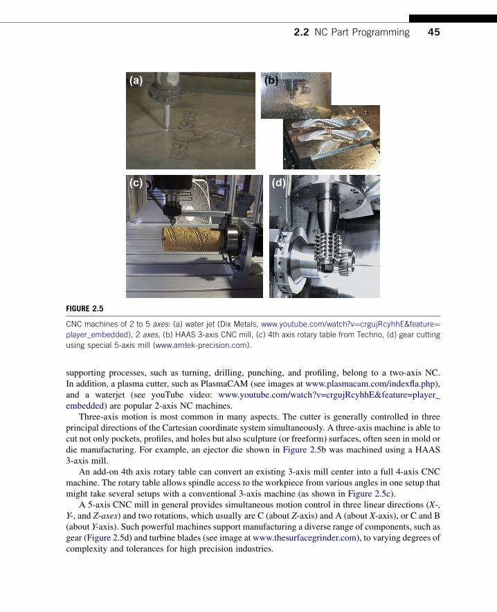
(a) (b)
(c) (d)
FIGURE 25
CNC machines of 2 to 5 axes (a) water jet (Dix Metals wwwyoutubecomwatchvfrac14crgujRcyhhEampfeaturefrac14player_embedded) 2 axes (b) HAAS 3-axis CNC mill (c) 4th axis rotary table from Techno (d) gear cutting
using special 5-axis mill (wwwamtek-precisioncom)
22 NC Part Programming 45
supporting processes such as turning drilling punching and profiling belong to a two-axis NCIn addition a plasma cutter such as PlasmaCAM (see images at wwwplasmacamcomindexflaphp)and a waterjet (see youTube video wwwyoutubecomwatchv=crgujRcyhhEampfeature=player_embedded) are popular 2-axis NC machines
Three-axis motion is most common in many aspects The cutter is generally controlled in threeprincipal directions of the Cartesian coordinate system simultaneously A three-axis machine is able tocut not only pockets profiles and holes but also sculpture (or freeform) surfaces often seen in mold ordie manufacturing For example an ejector die shown in Figure 25b was machined using a HAAS3-axis mill
An add-on 4th axis rotary table can convert an existing 3-axis mill center into a full 4-axis CNCmachine The rotary table allows spindle access to the workpiece from various angles in one setup thatmight take several setups with a conventional 3-axis machine (as shown in Figure 25c)
A 5-axis CNC mill in general provides simultaneous motion control in three linear directions (X-Y- and Z-axes) and two rotations which usually are C (about Z-axis) and A (about X-axis) or C and B(about Y-axis) Such powerful machines support manufacturing a diverse range of components such asgear (Figure 25d) and turbine blades (see image at wwwthesurfacegrindercom) to varying degrees ofcomplexity and tolerances for high precision industries
46 CHAPTER 2 Virtual Machining
222 Basic Concept of Part Programming
NC part programming consists of planning and documenting the sequence of processing steps to beperformed on an NC machine The outcome is an NC program used to machine a desired part An NCprogram describes the sequence of actions of the controlled NC machine which include but are notlimited to the following
bull Tool movements including direction velocity and positioningbull Tool selection tool change tool offsets and tool compensationbull Spindle rotation direction and spindle rotation speedbull Cutting speed for different sequencesbull Application of cutting fluids
All actions must be specified in the NC program as a set of blocks (typically hundreds or thousands)A block is a group of words terminated by the end-of-block character (usually a carriage return CR)Figure 26 shows a sample block which performs a cut from current cutter location to Xfrac14 235 and Yfrac140475 along a straight line at a feedrate of 5 inmin In this sample block there are seven NC wordseach word consists of an alphabet address character (also called identifier) followed by a numericcharacter In the sample block N100 is simply a sequence number of the block G01 and G41 are NCwords that prepare cutter motion where G01 specifies a linear motion and G41 turns on cutter radiuscompensations from the left X235 and Y0475 specify the next cutter location F50 specifies thefeedrate andM07 is a miscellaneous function which turns a flood coolant on A list of sample identifiersand NC words are listed in Appendices A and B respectively at the end of this chapter
In general there are three methods for creating NC programs manual computer-assisted andCADCAM (Figure 27) All methods aim at creating NC codes also called machine control data ormachine code data Most MCD (or NC code) is common among NC machines Some codes may bemachine-dependent that is a same NC word could mean something very different from one to anotherCNC machine which presents a potential pitfall in NC programming The computer-assisted andCADCAM approaches (to be discussed in the next subsections) offer assistance from computer andsoftware tools in generating NC codes that alleviates the burden of coding by hand to some extentBoth approaches generate cutter location data (CL data) to be translated to MCD througha post-processor
Manual NC programming is the most straightforward The MCD can be directly programmed andentered into the CNC machine for simple cuts for example see profile milling in Figure 28 In this
NC Word(Sequence Number)
N100 G01 G41 X135 Y-0475 F50 M07
Dimension Words
MiscellaneousFunction
Address Character
Preparatory Functions
FIGURE 26
Sample NC block
FIGURE 28
A profile milling example (a) desired toolpath and (b) NC codes with explanations
FIGURE 27
Approaches of NC programming
22 NC Part Programming 47
sample of profile milling a cutter of 075 in diameter is cutting an 8 in 5 in 1 in aluminumworkpiece along a prescribed profile the following is a desired toolpath
bull Tool start position 001bull Move the cutter to ndash037501bull Spindle speed 2000 rpm feedrate 25 ipm
(a) (b)
Toolpath displayed on monitor for machining the part shown below
FIGURE 29
NC code verification using (a) CNCezPro (wwwcncezprocom) and (b) HAAS 3-axis mill (wwwhaascom)
48 CHAPTER 2 Virtual Machining
bull Plunge into workpiece 05 in deepbull Cut along outside of profile formed by P1 up to P8bull Retract to 637501 (next to P8)bull Move the cutter back to the start position
Although simple and straightforward manual programming at the MCD level is notnecessarily the best First it is often time consuming to figure out cutter locations based on partgeometry Usually a few predefined programs (canned cycles such as hole-drilling) comewith the CNC unit which makes manual part programming a little easier Second the MCDis limited in supporting complicated machining work (eg contour surface milling) inwhich cutter locations on the surface must be accurately identified Third although MCDcommands and formats are fairly well standardized differences do exist between machinemanufactures As a result an NC part program that works on one machine may not work onanother one
It is critical that the MCD be verified before conducting actual cutting This can be done by eitherusing a third-party NC software tool such as CNCezPro (Figure 29a) or on the monitor screen of theCNC machine (eg HAAS 3-axis mill shown in Figure 29b)
223 Computer-Assisted Part Programming
Computer-assisted part programming methods are faster and more reliable than manual program-ming techniques There are a variety of forms of them The common feature of these programs is thatthe part and machining paths are not defined directly with G-code but through English-like state-ments or through interactive graphic instructions It consists of a series of English-like geometry andmotion statements which are used to define the workpiece and machine toolpath A widely usedlanguage is Automatically Programmed Tools (APT) and its variations Its instructions can becompiled and converted into G-code programs Readers may refer to Chang et al (1998) fora detailed discussion of APT
22 NC Part Programming 49
APT uses language statements to define part shape and tool motion as well as machine tool-dependent data (eg feedrates and spindle speeds) The general procedures of generating APTsource codes involve the following steps
1 Identify part geometry2 Identify cutter motions feeds speeds and cutter parameters3 Code the geometry cutter motions and general machine instructions into the part programming
languages The code is known as source4 Compile or process the source to produce the machine-independent list of cutter movements and
auxiliary machine control information known as the cutter location data file (or CL data)5 An APT processor program is used to read these statements interpret the meanings and perform all
the necessary calculations to generate a series of cutter location points that define the toolpath Thegeneralized APT output (usually in CL data) is converted to the particular format G-code requiredby the CNC machine using a post-processor program
6 The CL data file contains (mainly) details of cutter moves either as a series of absolute linearGOTO moves or relative GODLTA moves Note that the CL data is different from APT The CLdata is defined by the International Organization for Standardization (ISO)
7 Postprocess the CL Data to produce MCD for the particular target CNC machine8 Transmit the MCD to CNC machine and verify it
A major advantage of APT is that it has developed into an accepted standard for machine tools inaddition to alleviating the burden of coding at the very basic level A prime disadvantage of APT is thatit uses English-like commands to define geometry instead of the much more convenient graphicalmethods Note that the APT-type programming approach is being gradually replaced by the moreadvanced CADCAM approach
(a)
PARTNOEXAMPLEMACHINMILL5CUTTER075P0 = POINTndash1ndash10P1 = POINT000P2 = POINT00200P3 = POINT20200P4 = POINT20400P5 = POINT40400P6 = POINT40200P7 = POINT60200P8 = POINT6000L1 = LINEP1 P2L2 = LINEP2 P3L3 = LINEP3 P4L4 = LINEP4 P5L5 = LINEP5 P6L6 = LINEP6 P7L7 = LINEP7 P8L8 = LINEP8 P1
PL1 = PLANE00ndash05600ndash05 020ndash05SPINDL2000FEDRAT25COOLNTONFROMP0GOTO L1 TO PL1 ON L8GOLFT L1 PAST L2GORGT L2 TO L3GOLFT L3 PAST L4GORGT L4 PAST L5GORGT L5 TO L6GOLFT L6 PAST L7GORGT L7 PAST L8GORGT L8 PAST L1RAPIDGOTO P0COOLNTOFFENDFINI
(b)
FIGURE 210
The profile milling exampledAPTapproach (a) desired toolpath and geometry entities identified and labeled and
(b) APT source codes
50 CHAPTER 2 Virtual Machining
The same profile milling discussed earlier is employed as an example to illustrate APTprogramming As shown in Figure 210a the geometry of the contour profile is identified and labeledas points (P0 to P8) and line segments (L1 to L8) These are specified in the APT codes shown inFigure 210b The motion statements which describe the toolpath in relation to the part geometry aregiven in the codes such as GOTO GOLFT (toolpath to the left of the part) and GORGT RAPID
(a) (b)
O0100 (1) (010903-193923) N0010T1M06 S2000M03 G00X-375Y0 G43Z1H01M08 G01Z-5F25 Y2 G02X0Y2375I375J0 G01X1625 Y4 G02X2Y4375I375J0 G01X4 G02X4375Y4I0J-375 G01Y2375 X6 G02X6375Y2I0J-375 G01Y0 Z1 G00X-375 M30
PARTNO PLATE MACHIN UNCX01 1 UNITS INCHES LOADTL 1 SPINDL RPM 2000000000 CLW COOLNT FLOOD RAPID GOTO -03750000000 00000000000 10000000000 FEDRAT 2500000 IPM GOTO -03750000000 00000000000 -05000000000 GOTO -03750000000 20000000000 -05000000000 CIRCLE 00000000000 20000000000 -05000000000 $ 00000000000 00000000000 -10000000000 03750000000 GOTO 00000000000 23750000000 -05000000000 GOTO 16250000000 23750000000 -05000000000 GOTO 16250000000 40000000000 -05000000000 CIRCLE 20000000000 40000000000 -05000000000 $ 00000000000 00000000000 -10000000000 03750000000 GOTO 20000000000 43750000000 -05000000000 GOTO 40000000000 43750000000 -05000000000 CIRCLE 40000000000 40000000000 -05000000000 $ 00000000000 00000000000 -10000000000 03750000000 GOTO 43750000000 40000000000 -05000000000 GOTO 43750000000 23750000000 -05000000000 GOTO 60000000000 23750000000 -05000000000 CIRCLE 60000000000 20000000000 -05000000000 $ 00000000000 00000000000 -10000000000 03750000000 GOTO 63750000000 20000000000 -05000000000 GOTO 63750000000 00000000000 -05000000000 GOTO 63750000000 00000000000 10000000000 RAPID GOTO -03750000000 00000000000 10000000000 COOLNT OFF SPINDL OFF FINI
(c) (d)
CS0X
X
y
y
CS0CS1
CS1
CutterWorkpiece
Toolpath
Cutter
x x
yy
zz
FIGURE 211
The profile milling exampledCADCAM approach (a) solid models and toolpath (b) milling simulation (c) CL
data file and (d) MCD (or tap file)
23 Virtual Machining Simulations 51
(rapid retract) Auxiliary statements such as COOLNT ON (turn on coolant) FEDRAT (feedrate)SPINDL (spindle speed) are also specified
224 CADCAM Approach
The CADCAM approach is the most popular and advanced approach in generating CNC codes Theprocess starts with creating a reference (or design) model and workpiece and then assembling them inassembly mode For example the design model and workpiece of the profile milling discussed beforeare assembled as shown in Figure 211a
After the solid models are assembled users define manufacturing set up including choosinga workcell (eg a 3-axis mill) and coordinate system (or machine zero) Then users createa machining sequence (eg a profile-milling sequence) In the meantime users choose a cutter andspecify machining parameters (eg federate spindle speed) At this point a machining sequence iscompletely defined CADCAMwill generate a toolpath like that shown Figure 211a the toolpath wascreated using ProMFG for this example
The profile-milling sequence can also be simulated (eg in Vericut shown in Figure 211b) Notethat Vericut (wwwcgtechcom) is a third-party software that is integrated to ProMFG for CNCsimulation and G-code verification In addition the toolpath generated can be output as a CL data fileas shown in Figure 211c The CL data can be converted to MCD using a proper post-processor thatsupports CNC machines at shop floor As an example the MCD shown in Figure 211d is post-processed for a HAAS CNC mill which is also called a tap file
In the rest of the chapter we will focus on the CADCAM approach from a broader aspectdthat isvirtual machining simulations in support of product design
23 VIRTUAL MACHINING SIMULATIONSA typical process of conducting a virtual machining simulation using CADCAM tools involvescreating a design model (perfectly finished part) creating workpiece (a raw stock for machining)choosing manufacturing set up defining machining sequences generating toolpath checking theresults and postprocessing the toolpath for CNC codes as shown in Figure 212a
The manufacturing set up involves choosing a machine (eg a 3-axis mill) and defininga machining coordinate system (also called machine zero) usually on the front left corner of the topsurface of the workpiece for the NC sequence The definition of a NC sequence includes selecting thetool and retract plane (the plane to which the tool retracts after a cut) and defining machiningparameters (eg feedrate spindle speed) After a complete sequence is defined the toolpath can begenerated in the form of CL data Machining toolpath (Figure 212c) machining simulation(Figure 212b) and important machining sequence information such as machining time are generatedby the CADCAM software In addition a post-processor can be chosen to generate MCD (machinecontrol data)dM-codes and G-codes for a particular type of CNC machinedfrom the CL data
In the following we will use examples to illustrate the process of conducting virtual machiningincluding milling and turning operations We will focus more on milling and just mention turningbriefly This is because NC programming for turning sequences is often carried out manually since theX- and Z-coordinates of the cutter locations can be more easily acquired Creating NC codes through
(c)
Post-Processing
Create Design Model
Create Workpiece
Define Manufacturing Setup
Define Machining Sequences
Generate the Toolpath
Check Results
(d)
Workpiece
Drive Surface
Tool Containment Rectangle
(a) (b)
FIGURE 212
Virtual machining (a) a typical process (b) design model with workpiece (c) machining toolpath and
(d) machining simulation
52 CHAPTER 2 Virtual Machining
virtual machining is sometimes overkill However from a design perspective it is essential thatdesigners incorporate all NC operations when addressing manufacturability of the product includingdetecting potential manufacturing-related issues and coming up with an overall machining timeestimate for design trade-off if necessary
231 Basic Machining Simulations
Basic machining operations refer to milling sequences involving simple geometric features such asprofile milling hole-making pocket milling and so on These basic sequences can be performed usinga standard 3-axis mill
For a full-scale CADCAM system such as ProMFG or CAMWorks users will have to create 3Dsolid parts for the design model (and usually workpiece as well) in order to proceed For software toolsof CAM emphasis such as Mastercam a simple 2D wireframe is often sufficient to support basicmachining operations In this section we will use a simple example shown in Figure 213a to discussnumerous aspects of the basic machining operations This example involves profile milling pocketmilling and hole-making Figure 213b shows the toolpaths of the three NC sequences
Using a CAM software such as Mastercam a 2D wireframe that describes the geometry of theouter profile pocket and holes (Figure 213a) is sufficient for carrying out a virtual machiningoperation The size of the design model is 6 in 4 in Both corner radius and diameter of the four holesare frac34 in The radii of the large and small semicircles of the center pocket are 1 in and frac12 in
Profile (Blue)
Pocket (Blue)
Hole Drilling (Green)
Workpiece (Dotted)
(a) (b)
FIGURE 213
Basic machining sequences (a) machining simulation and (b) machining toolpaths
Design model (2D wireframe)
Workpiece (Dotted line)
Pocket (Blue)
(a) (b)
FIGURE 214
Basic machining example (a) 2D wireframe design model and (b) with workpiece in isoview
23 Virtual Machining Simulations 53
respectively A rectangular block of 6 in 4 in 075 in is added to the wireframe as a workpiece asshown in Figure 213b Note that the straight lines and the circular arcs in Figure 214a are created byentering end point locations center point locations radius and so on instead of creating solid featuresas those of CAD tools While entering the point locations a coordinate system was referred to Thiscoordinate system is implicitly defined as the reference so called the machine zero to which all CLdata of the toolpath refer
An end mill of 11 in diameter is chosen for the first NC sequence which is a profile milling (calledcontour milling in Mastercam) Some software (eg Mastercam) provides a detailed view on thegeometry of the cutter such as the one shown in Figure 215a Other software (eg ProMFG) requiresusers to enter basic parametersdfor instance cutter diameter and lengthdto define a cutter Ingeneral a cutter is represented as a cylinder in machining simulation for visual for example see thecutter of Mastercam shown in Figure 215b Note that Mastercam provides a predefined cutter library(Figure 215c) which helps users pick suitable cutters for machining In practice one will have to
FIGURE 215
Selecting a cutter (a) detailed geometry of an end mill in Mastercam (b) cutter in virtual machining simulation
and (c) prescribed tool library in Mastercam
54 CHAPTER 2 Virtual Machining
check the mechanist at the shop floor to ensure that the cutters selected for virtual machining corre-spond to those on the tool turret in the CNC machine
Several important cutting parameters are required for conducting profile milling In this examplethe (overall) depth of cut required for the profile milling is set to frac12 in Recall that the thickness of theworkpiece is frac34 in Therefore there will be a layer of frac14 in material intentionally left uncut aftercompletion of the profile pass The maximum step depth which defines how thick the cutter trimsaround the workpiece in one pass is set to frac14 in in this example Note that step depth is highly relatedto the size of the cutter among other factors In general a cutter of larger diameter has more strength toplunge deeper into the workpiece A cutter of stronger material (eg cutter of carbide inserts) allowsfor a larger step depth The rule of thumb is that the step depth has to be less than the radius of thecutter Since the (overall) depth of cut is frac12 in and the maximum step depth is frac14 in it will take twopasses for the cutter to go around the workpiece to complete the profile milling
Note that the extra stepsdlead in and lead out respectivelydwhen the cutter approaches andleaves the workpiece are often added to the profile toolpath as shown in Figure 216a Once thetoolpath is generated machining simulation can be shown like that of Figure 216b in for exampleMastercam
One practical issue that must be taken into consideration for profile milling is mounting theworkpiece to the workbench of a CNC machine Notice that in some cases the cutter may not be ableto cut a complete path around the workpiece without colliding with the clamps that hold the workpieceClamping and fixtures is an important issue in practice which will be discussed in Section 24
The second NC sequence is pocket milling For a pocket milling the cutter first plunges into theworkpiece then moves around to make a cut The cutter usually moves in one direction steps sidewayand cuts in the reverse direction The cutting pattern is similar to mowing the lawn in your backyardwhere we step sideways at the end of each pass before reversing the mowing direction This is one of
Toolpath
Lead In
Lead Out
(a) (b)
FIGURE 216
Profile milling sequence (a) toolpath and (b) milling simulation
Profile pass(a) (b) (c)
FIGURE 217
Pocket milling sequence (a) toolpath (b) milling simulation and (c) profile cut
23 Virtual Machining Simulations 55
the available scan patterns in CAM called zigzag Other scan patterns include spiral among otherswhere the cutter starts roughly from the center of the pocket and follows a spiral-like path andgradually moves outward
The amount of step sideways is called stepover It is obvious that stepover has to be less than thecutter diameter in order to make a clean cut As a rule of thumb the stepover is usually less than 80of the cutter diameter in practice After performing the scan passes another profile pass is added tomove the cutter around the wall of inner pocket boundary to clean up the remaining material along theboundary as shown in Figure 217a In this example the cutter chosen is a ⅜ in end mill in which thestep depth chosen is 16 in If we are cutting a frac12 in deep pocket it will take eight sets of complete scanand profile passes each 16 in deep to complete the pocket milling
Also in order to ensure a smooth inner pocket boundary it is a good practice to leave a thinmaterial layer around the boundary wall of the pocket and add a profile cut at the end to ensurea smoother pocket boundary similar to that of Figure 217c
The third NC sequence is hole-making There are four blind holes offrac34 in diameter at the cornersCreating virtual machining for hole-making is straightforward It is obvious that the drill you pick must
FIGURE 218
Hole-making NC sequence (a) detailed geometry of a drill in Mastercam and (b) toolpath
56 CHAPTER 2 Virtual Machining
have the same diameter as those holes or a drill of slightly smaller size with a follow-on boring orreaming operations In this case afrac34 in drill (Figure 218a) is chosen The toolpath generated is shownin Figure 218b
All three NC sequences can be easily combineddtoolpath and machining simulations can be likethose shown in Figures 213a and 213b respectively In addition the toolpath can be converted intoG-codes and M-codes as discussed earlier
232 Advanced Machining Simulations
Geometrically complex parts are commonly found in the automotive and aerospace industrieswhere molds and dies are manufactured for production The time spent to manufacture molds ordies of different sizes and complexities ranges from 1200 to 3800 hours (Sarma and Dutta 1997)Considerable time (49ndash72) is spent in contour surface milling for the design surfaces (thesurfaces to be machined) of molds and die Design changes in structural geometry due tofunctional considerations may affect manufacturing cost significantly and vice versa Amongdifferent types of machining operations contour surface milling is the most critical for mold anddie machining since surface milling directly affects the quality and accuracy of the designsurface
In practice a machining operation of a die or mold or any parts with sculpture (or freeform)surfaces involves four machining sequences First a face milling will clean up the mating surface forthe die Second sequence is usually a volume milling that removes material in the cavity at a fast speedOften a relatively large cutter is employed with a higher feedrate to remove material as fast as possiblewithout regard to surface finish Next is a local milling which is essentially a smaller-scale volumemilling that removes the remaining small chunk of material left from the previous volume millingsequence In general a smaller cutter is employed for local milling The last NC sequence is contoursurface millingda finish cut this is considered the most important machining sequence for sculpturesurfaces since the scallop height of the uncut material remaining on the machined surface determines
23 Virtual Machining Simulations 57
the surface quality of the machined part In addition a common practice suggests a small layer of stockshould remain on the surface of the cavity from volume milling and local milling in order to eliminatetool marks
Existing commercial virtual machining tools such as ProMFG CAMWorks and Mastercamsupport contour surface milling using various methods (eg isoparametric constant curvature andconstant scallop height) In this section we will assume ProMFG for machining a part of a 16 in 10 in 4 in block with a sculpture surface as shown in Figure 219a Note that the sculpture surfaceis lofted using four section sketches of respective circular arcs (Figure 219b) For this example wewill include a volume milling and a local milling assuming a 3-axis mill We will include a 5-axiscontour surface milling for finish cut The workpiece is a 16 in 10 in 4 in block Thecoordinate system CS0 at the top left corner of the workpiece as shown in Figure 219c is chosen asthe machine zero for this model
Two cutters are chosen for this example A 1 in end mill with corner radius frac14 in (Figure 220a) isselected for volume milling (ie the rough cut) Note that such a cutter is often referred to as bull millSeveral such cutters are commercially available for example a four- and two-flutes end mills is shownin Figure 220a Note that the sharp corner of an end mill is its weakest point The corner radius designof a bull mill strengthens the end mill by reducing chipping and providing longer tool life In mold
Machine zero
x
zCS0
(b)(a)
(c)
R650
R340
R684
400
1000
R803
FIGURE 219
Sculpture surface (a) solid model (b) section sketches and (c) with workpiece and machine zero
FIGURE 220
Cutters chosen for the machining operation (a) 1 in end mill with corner radius and (b) frac12 in ball cutter
FIGURE 221
Volume milling NC sequence (a) isoview and (b) end view
58 CHAPTER 2 Virtual Machining
applications both end and bull mill cutters have traditionally been used In addition to the bull milla frac12 in ball nose cutter (Figure 220b) is employed for both local milling and contour surface millingNote that a ball nose cutter tends to leave less tool marks on the machined surface thus leading toa better surface finish
For the volume milling the step depth and stepover are 05 in and 09 in respectively The scanpattern is back and forth along the longitudinal direction (x-axis of CS0) The resulting machinedsurface is shown in Figure 221 in which material remains on the surface and requires a following NCsequence for further clean up The machining time estimated by ProMFG is 37 minutes assuminga feedrate of 20 inmin Determining an adequate feedrate for a machining sequence is critical inpractice A fast feedrate will reduce overall machining time however it is subject to a possible roughsurface finish and a higher probability of cutter breakage and shorter tool life Feedrate will be dis-cussed in more detail in Section 24
FIGURE 222
Machined surface after the local milling sequence (a) ball nose cutter with stepover 04 in and step depth
02 in (b) end mill of corner radius 01 in with stepover 04 in and step depth 02 in and (c) end mill of
corner radius 01 in with stepover 04 in and step depth 005 in
23 Virtual Machining Simulations 59
For the local milling the step depth and stepover are 02 in and 04 in respectively Both aresmaller than those of volume milling This is mainly because a smaller cutter is employed Alsoa smaller feedrate 5 inmin is chosen for this sequence The scan pattern is spiral which is deter-mined by ProMFG The resulting machined surface is shown in Figure 222a in which surface issmoother but still requires further clean up and polish The machining time for the local milling isestimated by ProMFG as 137 minutes partly due to a smaller feedrate
The machined surface is certainly not acceptable for practical applications Before carrying outa contour surface milling is there any way to improve the quality of the machined surface Is thecurrent setup for local milling the best There are several possibilities that may provide a better resultFirst an end mill of the same diameter (frac12 in) but a smaller corner radius 01 in (vs frac14 in) requiresabout the same machining time Comparing with the first case shown in Figure 222a this bull millprovides a machined surface with a slightly better surfacedespecially in the area closer to the centerof the spiral pattern (Figure 222b) This is mainly due to the smaller surface curvature closer to thecenter of the spiral pattern in which a bull mill leaves less material than that of a ball nose cutter
How about step depth and stepover Which parameter will impact more to the surface quality Ingeneral it depends on the geometric shape of the design surface For a surface of high curvature
60 CHAPTER 2 Virtual Machining
a smaller step depth reduces the staircase type surface For a surface of small curvature one can affordto choose a larger stepover to reduce the machining time and yet lead to a relatively good surfacefinish Smaller stepover and smaller step depth will certainly give a better surface finish however itmay require substantially more machining time to complete the cut For example Figure 222c showsa much smoother machined surface created by using a smaller step depth 005 in in which themachining time jumps to more than 600 minutes assuming the same feedrate Note that in practiceone may increase the feedrate when a smaller stepover and step depth are employed resulting ina reduced machining time
Although surface quality is much improved spending 600 minutes for a local milling is probablytoo much Plus we will employ a contour surface milling to perform the finish cut which serves thepurpose of polishing the surface For this example we will stay with the first case (surface finish shownin Figure 222a) after completing the local milling sequence
The third NC sequence is contour surface milling for a finish cut using a 5-axis mill A step size of04 in and the same feedrate 5 inmin are chosen for this sequence As mentioned earlier there areseveral options in generating a toolpath for the contour surface milling We choose the surface isolineoption for toolpath generation where one parametric coordinate of the surface is fixed at prescribedvalues in order to generate cutter contact curves that stay right on the surface (Figure 223a) Note thatthe space between neighboring tool passes is in general less than the stepover specified More on the
Cutter
CS0x
y
CS0
r
r
Tool mark
Tool mark
(a) (b)
(c) (d)
FIGURE 223
Contour surface milling (a) toolpath for stepover 04 in (b) machined surface with stepover 04 in tool mark
visible (c) machined surface with stepover 02 in tool mark still visible and (d) machined surface with stepover
04 in and 005 in stock allowed tool mark removed
23 Virtual Machining Simulations 61
isoline option and toolpath generation will be discussed in Chapter 3 The machining time for thiscontour surface milling is estimated as 85 minutes based on a feedrate of 5 inmin Note that inpractice a higher feedrate is often employed for the final finish cut since the material remaining thesurface is usually minimum
The resulting surface by combining all three NC sequences can be seen in Figure 223b There areclear tool marks on the machined surface These marks were left from the previous sequencesmainly from the rough volume milling There are two ways to remove or minimize the tool marksFirst one may reduce the stepover for the contour surface milling A smaller stepover will lead toa surface with smaller scallop height therefore a better surface quality with less visible tool marks(Figure 223c) in which the stepover is reduced to 02 in However the machining time increasesabout twice (increased from 85 to 160 minutes) We will discuss more on the calculations of thescallop height in Chapter 3
Another approach and a better one is to specify a small layer of stock material uncut (stockallowed) while performing volume and local milling sequences The layer thickness should be slightlylarger than the desirable scallop height If such a stock material is specified in previous sequences toolmarks should be completely removed in theory With a stock material of 005 in and a smaller stepover(02 in) the machined surface does not reveal any tool marks as can be seen in Figure 223d
If combining all three NC sequences the overall machining time is about 334 minutes (37thorn 137thorn160) which is considered very good for machining such a sculpture surface
233 Turning Simulations
Part programming for turning is much simpler than that of milling This is mainly because that NCcode for turning only requires X- and Z-locations of the cutter A cutter for a turning operation onlymoves on the X-Z plane often following straight paths For example an area turning sequence thatremoves the material on the outside cylindrical and front end surfaces of a cylindrical block is shown inFigure 224 Note that when translating the toolpath to NC codes special attention may be required Ifyou are converting a toolpath created in ProMFG to HAAS CNC lathe there are several modificationsandor extra steps that need to be carried out For example the CL data output for the G02 and G03commands (circular interpolation) must use ldquoRrdquo values for radius If ldquoIrdquo or ldquoKrdquo values are presenta setting for the post-processor will need to be altered in order to force the output with ldquoRrdquo valuesAlso while selecting UNCL01P11 to postprocess the CL data for HAAS lathe this post-processordoes not output the X Z R (R is the radius of circular interpolation in G02 and G03) In additionthe post-processor does not output the F (feedrate) values with a decimal point which is required bythe HAAS controller Again a setting for the post-processor will need to be altered to output CNCcodes with correct format
Going over all the modeling and simulation work for a simple turning cut such as the areaturning shown in Figure 224b may not be the best option in terms of time and effort Plus thereare additional setups in the NC postprocess that are usually required for valid NC codes Thereforemanual coding is often more effective for the CNC lathe Even when machining a sculpture surfaceon turning operation a toolpath can be defined along a planar curve which is much easier to obtainmanually than that of milling often dealing with a surface As a result part programming forturning operations is usually carried out by collecting cutter location data on the X-Z plane andmanually composing NC programs
FIGURE 224
Area turning (a) material to be removed on the cylindrical and front end surfaces (b) turning toolpath and
(c) machined surface
62 CHAPTER 2 Virtual Machining
24 PRACTICAL ASPECTS IN CNC MACHININGSo far our discussion has been focused on virtual machiningdeverything is carried out in a virtualenvironment In a virtual environment almost anything can be set up and simulated Machiningsequences that look good on a computer do not guarantee they can be implemented physicallywithout any flaws For example a deep and narrow pocket may not be possible to cut since a smallsize cutter is usually short and will not be able to reach deep enough to the bottom of the pocketAlso for profile milling in a virtual environment a cutter moves around the outer boundary of theworkpiece without any problem In reality the workpiece must be clamped to the workbench of theCNC machine and cutter must not collide with the clamps What kind of clamp or fixture is suitablefor mounting the workpiece for a profile milling sequence
When a fixture is employed to mount the workpiece will the cutter run into the fixture Also howdoes one determine appropriate feedrate and spindle speed Which kind of cutters are suitable fora given workpiece material using selected NC sequences Most of such issues have been welladdressed in NC workbooks or machinist handbooks (eg Oberg et al 2012) We will discuss some ofthe common practical issues you may encounter in NC machining The goal of this section is toprovide you with some practical aspects in applying virtual machining to practical NC operations
24 Practical Aspects in CNC Machining 63
There are several principles you may want to consider while designing a part to be machined Theseprinciples usually lead to a part design that can bemachinedwith fewer problems First designers shouldconsider designing parts that can be made out of standard size material stock This will minimize theneed to go through additional machining sequences that cut a standard stock to the desired size Secondavoid deep pockets in parts you may not find a cutter long enough to reach the bottom of the pocketEven if you can the long cutter may deflect or break during deep pocket cutting Third keep all filletradii identical whenever possible and keep them larger than the radius of available cutters A large cutterwill not be able to cut a small fillet Fourth keep all hole sizes identical if possible and avoid odd-sizeholes As a result one or two drills are able to make all holes which minimizes the frequency for toolchange Hole sizes should in general match those of available drills Finally avoid having to cut the partfrom multiple sides if possible Certainly compromises will always have to be made when designinga new part with machining considerations However staying with the preceding principles as much aspossible will make the machining sequences more straightforward and usually less costly
In the following we will discuss three main issues (1) choice of jigs and fixtures (2) determinationof machining parameters including feedrate and spindle speed as well as cutter selection and (3)setting up NC machining In Appendix C we will use a HAAS mini-mill as an example to go overa few important steps in setting up a NC machining operation on a shop floor
241 Jigs and Fixtures
Mounting the stock material to the workbench (also called feed table) is often the most critical andtime-consuming element of part machining The stock material must be mounted in a way that all thetools are able to complete their paths without interfering with a fixture or the stock coming loose ormoving
The easiest way tomount stock is in a vise (Figure 225a) Once the vise is aligned andmounted to theworkbench the coordinate system for the part can easily be identified (more about this inAppendixC) Forcutting circular parts or placing bolt patterns at the end of shafts a self-centering 3-jaw chuck(Figure 225b) will save time Flat plate or sheet material can be clamped using the standard block anda clamp set can be used to fix generic parts to the table (Figure 225c)
When machining odd-shaped parts special jigs may have to be made It is important to be patient infastening the stock to the workbench The followings are a few examples that are employed to mountthe workpiece
(a) (b) (c)
FIGURE 225
Common jigs and fixtures (a) machinists vise (b) self-centering 3-jaw chuck and (c) block and clamp setup
(a) (b) (c)
FIGURE 226
Milling machine vise (a) plain vise (b) swivel base and (c) swivel base with vise
64 CHAPTER 2 Virtual Machining
The milling machine vise shown in Figure 226 is the most common type of workpiece-holdingdevice used on the milling machine The plain milling machine vise is used for holding a work-piece that has parallel sides The vise is bolted directly to the table using the T-slots in the machinetable (Figure 226a) The plain vise can be accompanied by a swivel base The swivel base(Figure 226b) is graduated in degrees and allows the vise to swivel in the horizontal plane The swivelbase gives the vise a greater degree of versatility (Figure 226c) but should be avoided when doingheavy rough-cutting operations because it reduces the rigidity of the setup
242 Cutters and Machining Parameters
The choice on cutters and workpiece material largely determine feedrate and spindle speed Cutters canbe grouped in two major categories high-speed steel (HSS) and carbide inserts as shown in Figure 227HSS cutters maintain hardness and strength at elevated temperature and are less expensive Two basictypes of HSS cutters are commercially available M-series (Molybdenum type) and T series (Tungstentype) M-series steels contain up to 10 molybdenum with chromium vanadium tungsten and cobaltT-series steels contain 12 to 18 tungsten with chromium vanadium and cobalt
M-series steels have generally higher abrasion resistance than T-series less distortion in heattreatment and are less expensive Carbide inserts endure high temperatures with high strength and
FIGURE 227
Cutters (a) HSS cutters and (b) carbide insert
Flat endmilld=cutter diameter
Axis of revolution
d
(a) (b)
Ball Nose CutterIf ball is not ldquoburiedrdquo in workpiece then a will be less than cutter diameter ie no cutting occurs at full tool diameter
Cutter Axis
a
Cutting edge
FIGURE 228
Cutters (a) flat endmill and (b) ball nose cutter
24 Practical Aspects in CNC Machining 65
hardness especially suitable for high-speed cutting The tungsten carbide (WC) cuts nonferrousabrasive materials and cast irons Titanium carbide (TiC) has higher wear resistance thanWC but is notas tough Titanium carbide cuts hard materials mainly steels and cast irons
From their geometric shape there are flat endmill (Figure 228a) ball nose cutter (Figure 228b)and bull mill (Figure 220a) In general endmills are suitable for face profile and pocket milling Aball nose cutter is more suitable for sculptural surface milling since there is less tendency to gougeusing a ball nose cutter
Two of the most critical machining parameters are spindle speed and feedrate Spindle speed N(rpm) is usually determined by the cutting speed V (inmin) that is
N frac14 V=ethpdTHORN (21)
where d is the cutter diameter (in) In general factors affecting the calculation of cutting speed include(1) the material being machined (steel brass tool steel plastic wood) (2) the material the cutter ismade from (carbon steel high-speed steel carbide ceramics) and (3) the economical life of the cutterthat is the cost to regrind or purchase new compared to the quantity of parts produced
You may find recommended cutting speeds in machining textbooks or handbooks for examplessee Tables 21a and 21b As shown in the tables cutting speed is provided in a large range This isbecause there are other factors to consider while determining cutting speed (eg type of the millingsequences) A rough cut usually requires a larger cutting speed thus a higher spindle speed in order toremove material fast Different data sources may offer cutting speeds that differ by sometimessignificant amounts Numbers obtained from machining handbooks are a good starting point You mayhave to make needed adjustments onsite
Once an adequate spindle speed is determined a feedrate f (inmin) can be calculated using thefollowing equation
f frac14 ft N n (22)
where n is the number of teeth on the cutter and ft is the feed per tooth (in) as depicted in Figure 229Factors that affect the feedrate include (1) type of tool (eg a small drill vs a large end mill) (2)surface finish desired (3) power available at the spindle (to prevent stalling of the cutter or workpiece)
Table 21 Recommended Cutting Speeds
(a) Recommended by Kalpakjian and Schmid (2010)
Workpiece Material
Cutting Speed (ms)
HSS Carbide Inserts
Aluminum Alloys 15 w 6 10 thornMagnesium Alloys 3 w 5 12 thornCopper Alloys 03 w 15 15 w 7
Steels 01 w 07 05 w 4
Stainless Steels 02 w 1 1 w 2
High-Temp Alloys 005 w 01 02 w 03
Titanium Alloys 01 w 1 05 w 2
Cast Irons 02 w 06 05 w 2
(b) Recommended by Krar et al (2010)
Workpiece Material
Cutting Speed (mmin)
HSS Carbide Inserts
Machine Steel 21 w 30 45 w 75
Tool Steel 18 w 20 40 w 60
Cast Iron 15 w 25 40 w 60
Bronze 20 w 35 60 w 120
Aluminum 150 w 300 300 w 600
ftV
Rack angle
Relief angle
FIGURE 229
Feed per tooth
66 CHAPTER 2 Virtual Machining
(4) rigidity of the machine and tooling setup (ability to withstand vibration or chatter) (5) strength ofthe workpiece (high feedrates will collapse thin-wall tubing) and (6) characteristics of the materialbeing cut (eg chip flow depends on material type and feedrate)
The recommended feed per tooth for high-speed steel and carbide inserts are listed in Table 22aand 22b respectively As shown higher feed per tooth is recommended for carbide insert cutters whilecutting hard materials such as steels Also higher feed per tooth is recommended for face milling thanend milling This is because more teeth are in contact with the workpiece in face milling thus a higher
Table 22 Recommended Feed per Tooth by Krar et al (2010)
(a) High-speed steel
Workpiece Material
Face Mills End Mills
in mm in mm
Aluminum 0002 055 0011 028
Brass and bronze 0014 035 0007 018
Cast Iron 0013 033 0007 018
Bronze 0012 030 0006 015
Tool steel 0010 025 0005 013
Stainless steel 0006 015 0003 008
(b) Carbide inserts
Workpiece Material
Face Mills End Mills
in mm in mm
Aluminum 0020 050 0010 025
Brass and bronze 0012 030 0006 015
Cast Iron 0016 040 0008 020
Bronze 0012 040 0008 020
Tool steel 0014 035 0007 018
Stainless steel 0010 025 0005 013
24 Practical Aspects in CNC Machining 67
feedrate While carrying out finish cut the feedrate can be turned up if material remaining is minimalAgain numbers obtained from machining handbooks only provide a good starting point
243 Setting a CNC Sequence
In this subsection wewill go over a few important points in setting up an NCmachining sequence at theshop floor These are the things that one must be aware of when anNC program is generated and is readyto carry out the machining sequence using a CNC machine Since there are wide varieties of machineswewill only discuss two key stepswithout referring to specificmachines The goal here is to provide youwith some ideas when bringing the part program to a CNCmill and to serve as a reminder that there arepractical issues to go over before a successful machining sequence can be carried out on the shop floorWe use aHAASmini-mill as an example to illustratemore detailed procedures and setups inAppendixCfor those who are interested in learning more or those who have access to a HAAS mill
After a workpiece is loaded and secured on the workbench two key steps are followed loading andsetting up tools and setting up work coordinate and machine zero
Loading cutters is one of the most important steps in setting a CNC machining sequence You maycollect all the needed cutters and follow the machine instructions to load them to the mill Once alltools are loaded into the tool changer the lengths of each must be measured You will also need tomeasure cutter diameters if tool radius compensations are included in your NC codes Before
FIGURE 230
Using edge finder to set up X-axis
68 CHAPTER 2 Virtual Machining
measuring lengths we first place a work coordinate (or machine zero) on the stock material in the sameplace that you have set it in CAM software (such as ProMFG or Mastercam) Machine zero is usuallyplaced at the front left corner of the top surface of the stock Usually we load a drill chuck with an edgefinding tool (Figure 230) into the spindle move the edge finder to the X position of the part using thejog handle and zero the X-axis We repeat the similar steps for setting up Y-axis
The Z-axis will be set after all the tools needed for machining are loaded Often the first cutter isadvanced into the spindle Then we position the tool tip over the top of the X and Y-zero We lower thetool and place a feeler gage (Figure 231) to set zero for Z-axis Since the Z axis is zeroed using the first
FIGURE 231
Z-axis offset and tool length offset
25 Commercial Machining Simulation Software 69
tool the length offset for tool one should be zero The thickness of the feeler gage must now besubtracted from the Z axis height The same steps will have to be repeated to measure or offset the toollengths for all cutters loaded
Once these two steps are completed you are ready to load the program to the machine Usuallya CNC mill is networked with a PC In that case an NC program can be loaded to the mill very easilyOnce a program is loaded it usually automatically becomes the selected program the mill will run It isa good practice to verify the toolpath on the monitor screen of the mill like that shown in Figure 29bbefore running the program
25 COMMERCIAL MACHINING SIMULATION SOFTWAREA large number of commercial CAM software tools can currently be obtained There is general-purpose CAM software that supports turning and milling sequences There are also special-purposecodes that focus on narrow tasks (eg software for creating a toolpath only for engraving)
General-purpose software offers adequate geometric modeling capabilities Most of them aretightly integrated with an existing CAD system Roughly the general-purpose CAM software can becategorized into three main groups in terms of how they relate to a CAD system The first groupincludes CAM as one of the modules in a CAD system such as ProMFG of ProENGINEER CAMmodule of CATIA CADCAMCAE system and CAM module of the NX Unigraphics The secondgroup refers to CAM as third-party software that is seamlessly integrated into commercial CADsoftware This includes CAMWorks (wwwcamworkscom) integrated with SolidWorks Inventor-CAM (wwwinventorcamcom) with Autodesk Inventor and so on The third group includes stand-alone CAM software that is not associated with any CAD systems (eg Mastercam SurfCAM (wwwsurfwarecom) and GibbsCAM (wwwgibbscamcom))
Special-purpose codes as mentioned earlier focus on narrow tasks Some of these codes includeArtCAM (wwwartcamcom) that supports sign makers woodworkers engravers and jewelers todesign and manufacture 3D or 2D products from their artwork
This section presents a brief overview on the commercially available CAM software We willinclude a short description for one or two of the software from each group The strength weaknesspros and cons of these codes will be briefly discussed
251 General-Purpose Machining Software
Major CAD systems such as ProENGINEER CATIA and NX are equipped with a CAM modulethat is part of the CAD and is seamlessly integrated with the respective CAD systems As mentionedbefore other major CAD systems (eg SolidWorks or AutoDesk) offer a CAM module that isdeveloped by a third party and is seamlessly integrated with the CAD systems as well All such CAMmodules provide excellent virtual machining capabilities in support of a broad range of machiningsequences including profile milling volume milling surface milling hole-making text-engravingand so on These capabilities support users to create virtual machining simulation generate a toolpathand convert the toolpath into CNC codes following the steps depicted in Figure 212a Development ofsoftware in this category essentially started with CAD and then extended to include CAM eitherthrough its own development and acquisition or via a third party
70 CHAPTER 2 Virtual Machining
The major advantage of these software tools is that they require a relatively short learning curve fornew CAM users This is mainly because the user is already familiar with the basic operations andprocedures of using the CAD portion of the software Learning CAM that is a built-in module ofa CAD system the user is familiar with is relatively straightforward However using CAD-centeredCAM module users must start with creating 3D solid models that represent design and workpieceeven for a simple cut such as hole drilling
One thing worth noting is that CAMWorks offers a knowledge base and Automatic FeatureRecognition (AFR) tools to help users in the machining processes The AFR technology analyzes solidmodel geometry and identifies machineable features (eg holes slots pockets and bosses) Theknowledge base is a self-populating database that contains information about the cutting tools andthe parameters used by the operator as well as information regarding the cutting tools available on theshop floor This database helps store the best practices at a centralized location in the tool room
On the other hand software such as Mastercam SurfCAM and GibbsCAM (all general-purposeCAM software) were developed and marketed with the sole purpose of supporting virtual machiningwhich is essentially CAM-centered These tools offer excellent capabilities for virtual machiningoften even more general and versatile than those integrated in CAD systems For example Mastercamprovides more options for generating a toolpath for contour surface milling including the constantscallop height option that was not available in ProMFG
In general virtual machining can be carried out with these tools using wireframe surface orsolid geometric entities For example a pocket milling or a profile milling only requires a simplewireframe sketch that describes the geometry of the pocket and profile boundary of the part This ismuch simpler and requires less effort compared with that of using a CAD-centered CAM moduleHowever none of the geometric entities created in such tools are parametric which are not suitablefor design changes They are created using points lines and patches as well as basic extrusionsweep and rotate operations Modeling capabilities in CAM-centered software are in general inferiorto those in CAD
252 Special-Purpose Machining Software
Special-purpose software offers toolpath generation for narrow tasks Some of these codes includeArtCAM and DeskCNC among many others These software tools are very much tailored for specificmachining tasks in narrow applications
ArtCAM supports sign makers woodworkers engravers and jewelers who design and manufac-ture 3D or 2D products from their artwork Users can create highly intricate personalized or custom 3Dmodels from 2D sketches or photographs The software guides users through the entire process fromconceptual sketch to the finished piece or mold An example of The Black Bull sign-making inArtCAM is shown in Figure 232a for reference
DeskCNC is another popular code for engraving The tool supports users to bring in drawingsphotographs or any other computer graphic image and convert it into a DXF file or into G-Code readyto be machined Screen captures in Figure 232b show the process of converting an image into theactual toolpath used in creating the finished engraving The original file is loaded into DeskCNC andconverted andor processed into a grayscale image by numerous available graphics filters Once theimage is processed DeskCNC converts the picture files directly into toolpaths for an engravingmachine
FIGURE 232
Examples of special-purpose software (a) ldquoThe Black Bullrdquo sign making in ArtCAM (wwwartcamcomvideos
2011-online-demo-catchuphtml) and (b) the process of converting an image into the actual toolpaths using
DeskCNC (wwwdeskamcomdeskarthtml)
25 Commercial Machining Simulation Software 71
Another special-purpose code worth-mentioning is CNCezPRO It is a real-time 3D simulator forCNC toolpath verification equipped with good real-time rendering and 3D visualization of tool cutsUsers are able to write edit and revise G- and M-codes and visualize the toolpath in real time Forexample a trajectory milling (or slot milling) on XZ (G18) and YZ (G19) planes can be generated andsimulated in CNCezPRO as shown in Figure 233a In addition a user-defined post-processor forcustomized G- and M-codes and a macro language for custom cycles make CNCezPRO a powerfultool-proving package for any shop Other similar software includes CNC Simulator (see Figure 233b)CutViewer (wwwcutviewercom) AutoEditNC (wwwbetatechnicalcomautonchtm) and CIMCOEdit (wwwcimcocom)
FIGURE 233
Examples of special-purpose software for manual CNC programming and toolpath verification (a) a trajectory
milling in CNCezPRO (wwwcncezprocom) and (b) pocket and profile milling using CNC Simulator (www
cncsimulatorcom)
72 CHAPTER 2 Virtual Machining
26 CASE STUDY AND TUTORIAL EXAMPLESIn this section we will present a case study where virtual machining is conducted for machining diesthat cast tracked vehicle roadarms In addition to virtual machining this case involves mold designusing ProMOLD a software module of ProENGINEER that supports mold design in a computer Thepurpose of presenting this case study is to demonstrate that virtual machining is applicable to practicalengineering applications in industry In addition tutorial examples including a name plate andsculpture surface machining will be discussed Step-by-step instructions for creating these tutorialexamples are given in tutorial M4 S4 and P4 at the end of this book
261 Case Study
Virtual manufacturing is applied to develop and simulate the manufacturing process for tooling thatcast tracked vehicle roadarms The die-casting process is assumed for fabricating green parts of theroadarm which involves design and machining of the cover and ejector dies The machined dies canthen be used to die cast the green parts of the roadarm Most die castings are made from non-ferrousmetals specifically zinc copper aluminum magnesium lead pewter and tin based alloys We assumethat the roadarms are made from aluminum which is light weight with high strength The schematicillustration of the manufacturing process is given in Figure 234 As shown in the figure die castingproduces two parts per operation in this design Volume milling and drilling are used to machine thegreen part for the final roadarms by removing extra material that remains in the spruce and runners aswell as drilling holes at each end
Two dies cover and ejector are designed using ProMOLD A sprue which is a countersink hole iscreated on the top face of the cover die as shown in Figure 235a Circular shape runners are createdbetween the cover and ejector dies In addition waterlines are created in both dies for coolingpurposes as shown in Figure 235a
The machining operations of the dies involve volume milling that removes most of the cavitymaterial (plus sprue and runners) local milling that cleans up material left from the volume milling
Cover die
Ejector die Green part
Machined parts
Remaining material
Cover die
Ejector die
Sprue
Waterlines
Runner
(a) (b) (c)
FIGURE 234
Schematic illustration of roadarm manufacturing process (a) mold design (b) explode view and (c) machined
parts
Waterlines
Runners Cavity
Spruce Waterlines
Runners Cavity Top
Face
(a) (b)
FIGURE 235
Design of cover and ejector dies (a) cover die and (b) ejector die
Table 23 Cutters Used for Volume Milling
NC 1 NC 2
Length 3 in 3 in
Diameter 1 in 025 in
Round 01 in 01 in
Table 24 Manufacturing Parameters for Volume Milling
NC 1 NC 2
Cut Feed 10 inmin 10 inmin
Step Depth 05 in 01 in
Stepover 07 in 02 in
Spindle speed 2000 rpm 2000 rpm
Machining Time 92 minutes 587 minutes
26 Case Study and Tutorial Examples 73
contour surface milling that further cleans up the cavity surface grinding that polishes the cavitysurface by removing the leftover scallops and hole drilling for the waterlines Hot work H13 die steelis selected as the material for the die workpiece For illustration purposes only volume milling andcontour surface milling performed on the cover die are shown To begin the machining operation forthe cover die a workpiece of 8 in 525 in 2 in rectangular block is first created
A 3-axis mill is assumed for performing two NC sequences of volume milling The first sequenceremoves the top thin layer of the workpiece to generate a smooth surface The thin layer thickness is0125 in The second volume milling cuts the cavity and runners Cutters and machining parameters ofthe NC sequences are listed in Tables 23 and 24 respectively As shown in Table 24 the machiningtimes of the two NC sequences are 92 and 587 minutes respectively
FIGURE 236
NC sequence 1 of volume milling (a) milling simulation and (b) toolpath
FIGURE 237
NC sequence 2 of volume milling (a) milling simulation and (b) toolpath
74 CHAPTER 2 Virtual Machining
Simulation of these two NC sequences in ProMFG is illustrated in Figures 236 and 237respectively The first sequence creates a smooth flat surface The second sequence cuts the cavity butgenerates stair case type surface which is not smooth Note that the distance between the stair layers iscontrolled by the step depth manufacturing parameter which is 01 in in this case The cavity surfacemust be machined again using contour surface milling for a smoother surface This will minimize thegrinding operation
A 3-axis mill is assumed for performing the contour surface milling Note that five-axis millusually produces better surface smoothness for contour surface milling The cutter of length 2 indiameter 025 in and round radius 0125 in is used for the contour milling The machining parametersare summarized in Table 25
Table 25 Manufacturing Parameters for Contour Surface Milling
Contour Surface Milling
Cut Feed 10 inmin
Stepover 025 in
Spindle Speed 2000 rpm
Machining Time 359 minutes
FIGURE 238
NC sequence of contour surface milling (a) milling simulation and (b) toolpath
26 Case Study and Tutorial Examples 75
The contour surface milling simulation is performed as shown in Figure 238a The toolpath of themachining operation is shown in Figure 238b The total machining time is estimated as 359 minutesNote that the cavity surface is still not smooth The scallop remaining on the cavity surface can bereduced by using a smaller stepover and manufacturing time will increase Grinding operations areoften employed to polish the cavity surface which is not simulated
Virtual Machining for Green PartWith the dies fabricated the die-casting process can be carried out Assuming the casting process hasbeen performed the roadarm green part shown in Figure 234b is obtained The volume milling isperformedfirst to remove the extramaterial remaining in the runners and sprue then to create holes in theroadarm Using the roadarm green part as the workpiece the 3-axis milling machine is again selected
The volume milling simulation for the center hole is presented as shown in Figure 239a Themachining time for thevolumemilling is found to be29minutes and the toolpath is shown inFigure239b
Using the preceding virtual manufacturing process the manufacturability of the optimal roadarmcan be verified In addition to the simulation and machining time estimate ProMFG generates cutter
FIGURE 239
Volume milling operation for the middle hole (a) milling simulation and (b) toolpath
76 CHAPTER 2 Virtual Machining
location data that can be converted into G-code and M-code for CNC using a proper post-processorCertainly special fixtures must be design and fabricated to support the machining sequences of thegreen part and cutting the hole of the roadarm
262 Tutorial Examples
A name plate and a sculpture surface example are included in the tutorial lessons This name plateexample involves profile and volume millings and is presented so that you may learn to use ProMFG
EXAMPLE 21 NAME PLATEThis tutorial example involves designing and creating a toolpath for machining a customized name plate ona 3 in 12 in ⅜ in workpiece using both ProMFG and Mastercam
Two NC sequences volume milling and engraving are created using ProMFG Nine letters ldquoName Platerdquoaresketched on the top surface of the rectangular block and extruded 18 in into the block as a cut feature as shown inFigure 240a Note that a CG Triumvirate Inserat font is chosen for the alphabets You may draw a spline curve andchoose ldquoPlace Along Curverdquo to place the text along the curve (see Figure 240b)
A 18 in end mill is picked to make the cut As shown in the machining simulation this small cutter is able toreach most pocket areas to make cuts except the narrow area (eg the narrow cross line in the letter N) and sharpcorner In general the toolpath generated for volume milling is acceptable
Note that in creating a volume milling sequence using ProMFG users will have to create a ldquomill volumerdquo whichdefines the portion of the workpiece to be removed In using ProMFG creating a mill volume involves makinga sketch extruding the sketch for a solid block and intersecting the block with the design model to generate a trimsolid feature that represets exactly the material to be removed For some intricate surfaces ProMFGmay not be ableto process the trim function
The toolpath for the engraving sequence in this example is created using a Groove feature in ProENGINEER Asshown in Figure 240d six lettersdldquoGrooverdquodin an outline style are defined in the design model The same cutterwith a step depth 18 in is chosen for the engraving NC sequence Note that the text engraved will have the samesize as the cutter (18 in) that is the cutter will move one pass along the outer profile of individual letters
A similar name plate design is created for Mastercam as shown in Figure 241a The MC9 font is chosen tocreate the ldquoMASTERCAMrdquo text Note that a simple 2D wireframe sketch is sufficient for this machining simulationthere is no need to create 3D solid models Two sequences are created a profile milling that cuts along the outerboundary of the workpiece and a volume milling that cuts the area between the inner boundary curve and the outerprofile of individual letters A 18 in end mill with a step depth of 18 in is picked to make the cut The toolpath(profile milling and volume milling combined) and machining simulation are shown in Figures 241b and 241crespectively
FIGURE 240
CNC sequences for machining a name plate using ProMFG (a) creating text for volume milling (b) adding
a spline (c) machining simulation in Vericut and (d) adding text for an engraving sequence
10
10
05 02
(a)
(b) (c)
FIGURE 241
Volume CNC sequences for machining a name plate using Mastercam (a) creating text for volume milling
(b) combined toolpath and (c) machining simulation
26 Case Study and Tutorial Examples 77
andor Mastercam in projects P4 and M4 respectively In addition after going through this simpleexample you should see the major differences between the two software tools and hopefully be able toidentify a few pros and cons of each Once you are more familiar with one of these two software toolsyou may move to the second tutorial exampledblock with a sculpture surfacedin which both rough
78 CHAPTER 2 Virtual Machining
and finish cuts are required Three CAM software ProMFG Mastercam and CAMWorks areemployed for this example Since some information about this example has been discussed in Section23 using ProMFG we will focus more on Mastercam Machining the block using CAMWorks isdiscussed in Tutorial S445 This example should help you become more familiar with ProMFGMastercam andor CAMWorks
EXAMPLE 22 BLOCK WITH A SCULPTURE SURFACENC sequences for machining the sculpture surface of the block example discussed in Section 23 is chosen as thesecond tutorial example As discussed in Section 23 three NC sequencesdvolume milling local milling andcontour surface millingdwere employed for machining the surface using ProMFG This example focuses on usingMastercam to create a similar machining simulation
We will create three sequences using Mastercamdsurface rough flowline rough-restmill and surface finishdwhich correspond to volume milling local milling and contour surface milling in ProMFG Since creating thesculpture surface by blending circular arcs on four parallel planes using Mastercam is more time consuming we willimport the ProENGINEER part of the block into Mastercam Mastercam supports model import directly from ProENGINEER in addition to other CAD systems (eg SolidWorks CATIA and AutoDesk)
The ProENGINEER part will be imported into Mastercam in a default position and orientation similar to that ofFigure 242a The imported geometric entities usually must be rotated and translated to a proper position andorientation (similar to those shown in Figures 242b and 242c) so that the machine zero coincides and aligns withthe coordinate system built in Mastercam
A surface rough flowline with a 1 in bull mill of frac14 in corner radius was chosen for the rough cutFlowline is one of the several options available in Mastercam Flowline cuts single or multiple surfacesusing their natural shape to define the toolpath Stepover and step depth are 04 in and 02 inrespectively These parameters are identical to those defined in ProMFG A flowline direction along
FIGURE 242
Adjusting position and orientation for the imported part (a) default position and orientation (b) rotate 90 alongX-axis and (c) rotate 90 along Z-axis and then translate 4 units along the Z-axis
(a) (b)
(c)
FIGURE 243
Surface rough flowline machining in Mastercam (a) flowline direction (b) toolpath and (c) machining
simulation
26 Case Study and Tutorial Examples 79
the short edge of the surface (Figure 243a) is chosen The resulting toolpath and machining simulationare shown in Figure 243b and 243c respectively
As can be seen in Figure 243b Rough Flowline does a similar cut to that of volume milling inProMFG Mastercam does not require defining mill volume as that of ProMFG and requires fewersteps to generate a similar toolpath
The next sequence is Rough-Restmill which removes remaining materials from the previousrough cut Rough-Restmill is very similar to local milling in ProMFG The same frac12 in ball-nose cutter and the same stepover and maximum step depth are chosen to perform thissequence The resulting toolpath and machining simulation are shown in Figure 244a and244b respectively Note that the restmill toolpath follows a spiral pattern similar to that of ProMFG
The third and final sequence is finish cut A finish-scallop and the same frac12 in ball-nosecutter are chosen The finish-scallop option generates finishing toolpaths that have consistentscallop heights over the entire set of surfaces which is a desired option to perform a finish cutA maximum stepover 005 in is specified for this sequence Note that a similar option is notavailable in ProMFG The resulting toolpath and machining simulation are shown inFigure 245a and 245b respectively As shown in Figure 245b the surface looks fairly smooth
(a) (b)
FIGURE 244
Surface rough restmill machining in Mastercam (a) toolpath and (b) machining simulation
(a) (b)
FIGURE 245
Surface finish-scallop machining in Mastercam (a) toolpath and (b) machining simulation
80 CHAPTER 2 Virtual Machining
This is because a very small maximum stepover (005 in) is specified for the finish cut Asa result the overall machining time estimated is 7 hours and 18 minutes as reported byMastercam
27 SUMMARYIn this chapter we discussed the subject of virtual machining including NC part programming virtualmachining simulations simulation software that is commercially available as well as a case study andtutorial examples In addition we briefly addressed the practical aspects in CNC machining includingjigs and fixtures cutters and machining parameters and steps in operating HAAS mini-mill We hopethis chapter has helped you become more familiar with the subject With more practice you shouldbecome more confident and competent in using virtual machining simulation tools to address the
Questions and exercises 81
manufacturability of the product and obtain reasonable machining time estimates and required setup tosupport product design
In the next chapter we will introduce the topic of toolpath generation which is the backbone ofvirtual machining simulation It should provide you with a more in-depth understanding on the factorsthat contribute to the CNC toolpath generated in virtual machining simulation For those who areconducting research relevant to virtual machining or toolpath generation Chapter 3 should serve wellas an introductory article for understanding toolpath generation For practicing engineers the chapteroffers behind-the-scene operations in the calculation of cutter location data and parameters that affectthat data Knowledge acquired will help you diagnose problems encountered on the machined surfaces(eg gaging)
In the remaining chapters of this book we will describe other pertinent technology that supportsaddressing the manufacturing issues from design perspectives including sheet forming simulation(Chapter 4) rapid prototyping (Chapter 5) and manufacturing cost estimates (Chapter 6) CNCmachining discussed in this chapter and rapid prototyping in Chapter 5 offer a means to support fastprototyping in product development These chapters should provide you with a very good under-standing on the essential topics involved in product manufacturing using advanced computer-aidedtechnology
QUESTIONS AND EXERCISES
21 Write a CNC program (with explanations for each block) for a HAAS mill to machine a 4 in
425 in 25 in aluminum block for the part (design model) shown in the following image andtable Choose your own cutters (from those shown in the table) and cutting parameters (step depthand stepover) with ldquocommon senserdquo Note that you need to use tool radius compensation for alltoolpaths Calculate the overall cutting time
Size (inches) Type Length (inches)18 Ball-nose 0375 316 Ball-nose 1000 14 Ball-nose 0625 12 Ball-nose 2000 18 Flat-end 0375 316 Flat-end 0475 14 Flat-end 0500 14 Flat-end 0875 516 Flat-end 0600 38 Flat-end 0600 12 Flat-end 1000 12 Flat-end 1500
22 Verify your NC program of 21 using an adequate software tool Search and find a softwareprogram that takes your NC program and simulates the NC sequence
82 CHAPTER 2 Virtual Machining
23 Write a NC program to cut a 025 in-deep pocket on a 3 in 3 in 05 in block shown in thefollowing figure The cutter diameter is 05 in Note that the cutter will cut inside of the pocket bymoving along the pocket boundary only one time which will leave some material uncut Youmust use tool radius compensation for the NC codes Identify the uncut area Also sketch yourtoolpath which must start from point A
Point A
B
24 Write a complete APT (Automatically Programmed Tools) program to cut a 025 in-deep pocketon a 3 in 3 in 05 in block shown in the following figure The cutter diameter is 075 in Notethat spindle speed is 580 and feedrate is 23 Note that the cutter must start from point SP andreturn to SP after the cut
P1
SP
P4 P3
P2
L3
L1
L2 L4
25 Use ProMFG CAMWorks or Mastercam (or other CAM software you have access) to machinethe design model shown below (left) from a workpiece of 12 in8 in45 in (show below right)Note that at least two NC sequences are needed face milling that removes top layer of 05 in deepfrom top surface of the workpiece then pocket milling that cuts the pocket
Questions and exercises 83
26 Design and machine a nameplate on a 3 in12 in ⅜ in Plexiglas workpiece using theHAAS CNC mill (or other mill you have access) Note that you can design your plateusing ProMFG (CAMWorks or Mastercam) directly write your CNC codes using HAAScommands or any other software tools that you found This will be a combination of textengraving volume and trajectory milling and picturelogo carving The following is whatyou need to submit for grade Please BE VERY CREATIVE(a) Your design describe it briefly in a few sentences and use pictures for illustration(b) Your CNC codes with explanations (only important blocks no need to submit the entire NC
program)(c) Final machined nameplate (if applicable)(d) Two significant things that you learned from using the mill
ReferencesChang T-C Wysk RA Wang H-P 1998 Computer-Aided Manufacturing second ed Prentice HallKalpakjian S Schmid SR 2010 Manufacturing Engineering and Technology sixth ed Prentice HallKrar S Gill A Smid P 2010 Technology of Machine Tools seventh ed McGraw-HillOberg E Jones F Horton H Ryffel H McCauley C 2012 Machineryrsquos Handbook twentyninth ed
Industrial PressSarma R Dutta D 1997 An integrated system for NC machining of multi-patch surfaces Computer-Aided
Design 29 (11) 741ndash749Smid P 2000 CNC Programming Handbook second ed Industrial Press Inc 200 Madison Avenue New York
NY 10016-4078
84 CHAPTER 2 Virtual Machining
APPENDIX A SAMPLE ADDRESS CODES
A Fourth-axis rotary motion The A address character is used to specify motion forthe optional fourth A axis It specifies an angle indegrees for the rotary axis It is always followed bya signed number and up to three fractional decimalpositions
B Fifth-axis rotary motion The B address character is used to specify motion forthe optional fifth B axis It specifies an angle indegrees or the rotary axis It is always followed bya signed number and up to three fractional decimalpositions
C Auxiliary external rotary axis The C address character is used to specify motion forthe optional external sixth C axis It specifies an anglein degrees for the rotary axis It is always followed bya signed number and up to three fractional decimalpositions
D Tool diameter selection The D address character is used to select the tooldiameter or radius used for cutter compensation
F Feedrate The F address character is used to select the feedrateapplied to any interpolation functions including pocketmilling and canned cycles
G Preparatory functions (G-codes) The G address character is used to specify the type ofoperation to occur in a block
H Tool length offset selection The H address character is used to select the tool lengthoffset entry from the offsetrsquos memory
I J K Canned cycle and circular optionaldata
The I J and K address character is used to specify dataused for some canned cycles and circular motions
L Loop count for repeated cycles The L address character is used to specify a repetitioncount for some canned cycles and auxiliary functions
M Code miscellaneous functions The M address character is used to specify an M-codefor a block These codes are used to controlmiscellaneous machine functions
N Number of block The N address character is entirely optional It can beused to identify or number each block of a program
R Canned cycle and circular optionaldata
The R address character is used in canned cycles andcircular interpolation
S Spindle speed command The S address character is used to specify the spindlespeed
T Tool selection code The T address character is used to select the tool for thenext tool change
X Y Z Linear X- Y- and Z-axis motions The X- Y- and Z-address characters are usedto specify motion for the X-axis It specifiesa position or distance along the X- Y- and Z-axesrespectively
Appendix B Sample G- and M-Codes 85
APPENDIX B SAMPLE G- AND M-CODES
G-Code Function
G00 Rapid Motion
G01 Linear Interpolation Motion
G02 CW Interpolation Motion
G03 CCW Interpolation Motion
G04 Dwell
G12 CW Circular Pocket Milling
G13 CCW Circular Pocket Milling
G17 XY Plane Selection
G18 ZX Plane Selection
G19 YZ Plane Selection
G20 Select Inches
G21 Select Metric
G28 Return to Reference Point
G29 Return From Reference Point
G40 Cutter Comp Cancel
G41 2D Cutter Compensation Left
G42 2D Cutter Compensation Right
G43 Tool Length Compensation thornG44 Tool Length Compensation G47 Text Engraving
G49 G43G44G143 Cancel
G80 Canned Cycle Cancel
G81 Drill Canned Cycle
G82 Spot Drill Canned Cycle
G83 Normal Peck Drill Canned Cycle
G84 Tapping Canned Cycle
G85 Boring Canned Cycle
G86 BoreStop Canned Cycle
G87 BoreStopManual Retract Canned Cycle
G88 BoreDwellManual Retract Canned Cycle
G89 BoreDwell Canned Cycle
G90 Absolute
G91 Incremental
G98 Initial Point Return
G99 R Plane Return
M-Code Function
M00 Stop Program
M01 Optional Program Stop
M02 Program End
M03 Spindle Forward
M04 Spindle Reverse
M05 Spindle Stop
M06 Tool Change
M08 Coolant On
M09 Coolant Off
M30 Prog End and Rewind
M97 Local Sub-Program Call
M98 Sub Program Call
M99 Sub Program Return or Loop
86 CHAPTER 2 Virtual Machining
APPENDIX C HAAS MINI-MILLWe use a HAAS mini-mill as an example to illustrate detailed procedures and setups for those who areinterested in learning more andor those have access to a HAAS mini-mill
Basic Machine ConfigurationThe HAAS mini-mill is a 3-axis mill with a work envelop 16 in 12 in 10 in as shown inFigure 246 The maximum spindle speed and rapid feed are 6000 rpm and 600 ipm (inmin)respectively There are 10 tool changers in the tool pocket (or tool turret) which are able to hold 10
(b)(a)
Jig table
Tool Pockets
Spindle
Coolant tube
FIGURE 246
HAAS mini-mill (a) exterior and (b) interior
Appendix C HAAS Mini-Mill 87
different cutters The mini-mill is relatively less expensive and is affordable for academia and a smallshop All stock material that will be machined must be rigidly mounted to the jig table The machinistmust be aware of oversized stock material extra jig components (eg clamps and vises) andextended-length milling tools to avoid collision with the spindle
Prestart and Power-UpBefore powering up the mill there are a few things to checkdfor example coolant liquid level airpressure and so on
Power-Up
The green button at the top left corner of the control panel (Figure 247) will turn on the mill Themachine will boot up and an alarm message will appear Not to worry this is normal it simply meansthat the mill has not gone through a calibration process yet Press the ZERO RET button on the controlpanel then the AUTO ALL AXES button to calibrate the machine Make sure the millrsquos door is closedThe table will move to the nearest left corner with the spindle retracted to the highest point Themachine is now powered up and ready for user control
The HAAS mill uses six modes of operation to complete the tasks needed for milling a part theyare circled in Figure 247 (left most column) The user must enter one of these modes in order to useany of the four action buttons to the right
Moving the Jig TableEnter the jog mode by pressing the HANDLE JOG button (Figure 247) Press the 1100 button thiswill move the table 01 inches per tick of the jog handle in the corresponding direction The user canspecify a smaller increment using the remaining action buttons
POWER ONOFF
SPINDLE LOAD
E - STOP
JOG HANDLE
FIGURE 247
HAAS mini-mill control panel with action buttons
(a) (b)
FIGURE 248
Moving the jig table (a) axis jog buttons and (b) jog handle
88 CHAPTER 2 Virtual Machining
Press the thornX or X button (Figure 248a) The buttons surrounding the JOG LOCK button are forthe user to select which axis is to be moved Rotate the jog handle (Figure 248b) in the clockwise orpositive direction to move the table right Position the table so that it will be easier to mount yourworkpiece
Tool LoadingLoading cutters is one of the most important steps in presetting a CNC machining sequence You maycollect all the needed cutters and follow the steps to load them to the mill First enter the MDI mode(Manual Data Input) (see Figure 247) Press ATC FWD or ATC REVuntil tool one is in the spindle Getthe tool to be loaded and insert it in the spindle as far as it will go Press and hold the TOOL RELEASEbutton (see Figure 249) A blast of air will shoot out of the spindle to clear any debris Push the tool upinto the spindle and release the button
FIGURE 249
Tool release and program reset
FIGURE 250
Work coordinate list
Appendix C HAAS Mini-Mill 89
Work Coordinate SetupThe work coordinate must be placed on the stock material in the same place that you have set it inProMFG or Mastercam (or other CAM software) The HAAS mini-mill has 14 different workcoordinates that can be set independently of one another (see Figure 250) The OFSET button can betoggled to view these coordinate offsets (see Figure 251) While the screen is displaying the offsets forthe coordinates use the up and down arrows in the center of the control panel to select the X-axis forthe coordinate system the user will be working in The default coordinate system is G54
Axis Part ZeroNow we are setting the machine zero (or axis part zero) using the following steps
1 Load a drill chuck with an edge-finding tool (Figure 252) into the spindle2 Enter HANDLE JOG mode (see Figure 247) Note that the display on the screen will not change3 Turn the spindle clockwise using the CW button (Figure 253)4 Move the edge finder to the X position of the part using the jog handle (Figure 254)5 Press PART ZERO SET (Figure 249) to zero the X-axis The Y-axis should now be highlighted in
the display
FIGURE 251
Display menu
FIGURE 253
Spindle and feed control
FIGURE 254
Using edge finder to setup X-axis
FIGURE 252
Feeler gage and edge finder
90 CHAPTER 2 Virtual Machining
G90 G54 G00 X0 Y0
FIGURE 255
X-Y coordinate zero check
Appendix C HAAS Mini-Mill 91
Repeat steps 3 through 5 to zero the Y-axis The Z-axis will be set after all the tools needed formilling are loaded
Z-Axis OffsetOnce all tools are loaded into the tool changer the lengths of each must be measured First the Z-axis isoffset using a feeler gage (Figure 256)
1 Advance tool 1 into the spindle by enteringMDImode and typing T1 then press theWRITE buttonin the lower right of the control panel
2 Press ATC FWD to move directly to tool 2 Be sure the part is out of the way before the tool changewhen using extended-length tools
3 Check the X- and Y-axis zero points by entering the contents of Figure 255 into MDI modeThe block G54 may be changed if the user selects a different coordinate system (eg G55 G59)
4 Close the door and press CYCLE START (Figure 248b) This will load into memorywhich coordinate system you will be using as well as move the table to the X-Y zero position
5 Position the tool over the area in which the Z offset can be measured there must be room for thefeeler gage as well (Figure 256)
6 Press OFSET and use the arrow keys to highlight the Z-axis offset under the proper coordinatesystem
7 Press PART ZERO SET (Figure 249) to zero the Z-axis
FIGURE 256
Z-axis offset and tool length offset
92 CHAPTER 2 Virtual Machining
Tool Offset MeasureThe lengths of each tool will be based on that of tool 1 Since the Z-axis is zeroed using tool 1 thelength offset for tool 1 should be zero Check this by toggling the OFSET button (Figure 251) todisplay the tool offset lengths Highlight tool 1 and press TOOL OFSET MESUR (Figure 249) thevalue should become zero
Offsetting ToolsDo the following to use the offsetting tools
1 Retract the tool using the handle jog Z-axis positive direction2 Press ATC FWD to the next tool and handle jog it down to the Z zero surface using the feeler gage3 Highlight the tool in the offset display and press TOOL OFSET MESUR (Figure 249) The value
that appears will be the difference in length of the tool in the spindle to tool 24 Repeat previous steps until all tools are measured
The thickness of the feeler gage must now be subtracted from the Z-axis height Toggle the OFSETdisplay to the work coordinate offsets Highlight the Z-axis and type in the negative of the feeler gagethickness and press WRITE
Loading a ProgramOnce a program is loaded using the following steps it automatically becomes the selected program themill will run if the cycle start button is pressed
1 Press LIST PROG (Figure 247) to start the program control mode programs are downloadeduploaded and deleted from this mode
2 Type in the program number starting with the letter ldquoOrdquo before the number3 Press WRITE4 Press RECV RS232 (Figure 247) to prepare the mill to receive a file from the connected computer5 Start the NCnetLite program on the computerrsquos desktop6 Click the green thumbs up button to connect to the mill (Figure 257)7 Click the transmit button and select the file to send The file is automatically sent after the OK
button is selected
THUMBS UP TRANSMIT
FIGURE 257
Loading NC program
Appendix C HAAS Mini-Mill 93
A program can be edited if the user enters the EDIT mode It is recommended that onlysmall changes be made in this mode due to the limited ability to verify the toolpaths after thispoint
Running a ProgramAfter doing the following steps do not increase the rapid feed until the program has verified that thefirst few cuts are correct
1 In the LIST PROG mode highlight the program to be run then press SELECT PROG (Figure 247)2 Enter the MEM mode and change the display by pressing CURNT COMDS (Figure 253)3 Reduce the rapid motion to 5 (Figure 253) and run the program by pressing CYCLE START
(Figure 248b)
If the cuts are not correct press the FEED HOLD (Figure 248b) button to stop the table feed thenpress RESET to turn off the spindle and coolant (Figure 249) Handle jog the tool out of the part andcall the shop supervisor for assistance
Once the program has completed remove the part and tools then clean the mill from any materialchips or spilled coolant
- 2 Virtual Machining
-
- 21 Introduction
- 22 NC Part Programming
-
- 221 Basics of NC Machines
- 222 Basic Concept of Part Programming
- 223 Computer-Assisted Part Programming
- 224 CADCAM Approach
-
- 23 Virtual Machining Simulations
-
- 231 Basic Machining Simulations
- 232 Advanced Machining Simulations
- 233 Turning Simulations
-
- 24 Practical Aspects in CNC Machining
-
- 241 Jigs and Fixtures
- 242 Cutters and Machining Parameters
- 243 Setting a CNC Sequence
-
- 25 Commercial Machining Simulation Software
-
- 251 General-Purpose Machining Software
- 252 Special-Purpose Machining Software
-
- 26 Case Study and Tutorial Examples
-
- 261 Case Study
- 262 Tutorial Examples
-
- 27 Summary
- Questions and Exercises
- References
- Appendix A Sample Address Codes
- Appendix B Sample G- and M-Codes
- Appendix C HAAS Mini-Mill
-
- Outline placeholder
-
- Basic Machine Configuration
- Prestart and Power-Up
-
- Power-Up
-
- Moving the Jig Table
- Tool Loading
- Work Coordinate Setup
- Axis Part Zero
- Z-Axis Offset
- Tool Offset Measure
- Offsetting Tools
- Loading a Program
- Running a Program
-
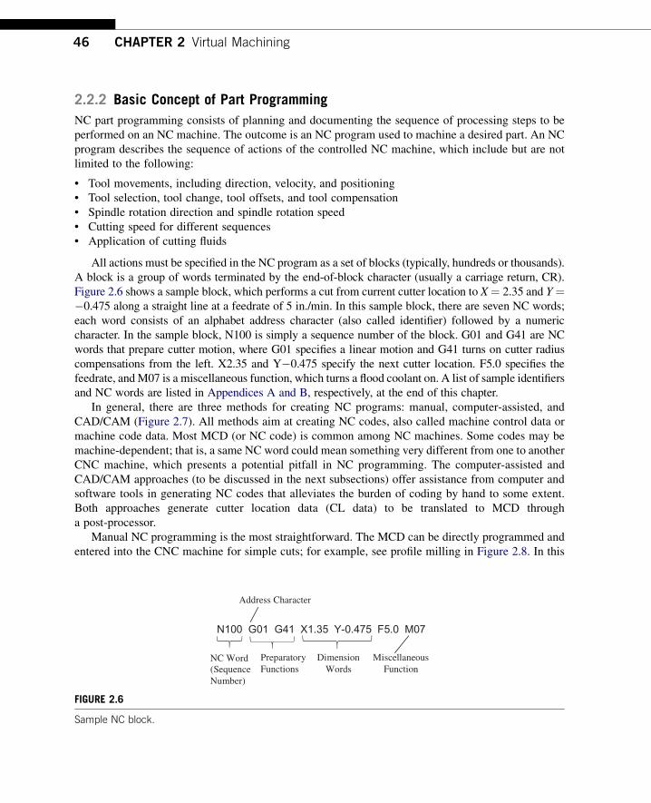

(a) (b)
Toolpath displayed on monitor for machining the part shown below
FIGURE 29
NC code verification using (a) CNCezPro (wwwcncezprocom) and (b) HAAS 3-axis mill (wwwhaascom)
48 CHAPTER 2 Virtual Machining
bull Plunge into workpiece 05 in deepbull Cut along outside of profile formed by P1 up to P8bull Retract to 637501 (next to P8)bull Move the cutter back to the start position
Although simple and straightforward manual programming at the MCD level is notnecessarily the best First it is often time consuming to figure out cutter locations based on partgeometry Usually a few predefined programs (canned cycles such as hole-drilling) comewith the CNC unit which makes manual part programming a little easier Second the MCDis limited in supporting complicated machining work (eg contour surface milling) inwhich cutter locations on the surface must be accurately identified Third although MCDcommands and formats are fairly well standardized differences do exist between machinemanufactures As a result an NC part program that works on one machine may not work onanother one
It is critical that the MCD be verified before conducting actual cutting This can be done by eitherusing a third-party NC software tool such as CNCezPro (Figure 29a) or on the monitor screen of theCNC machine (eg HAAS 3-axis mill shown in Figure 29b)
223 Computer-Assisted Part Programming
Computer-assisted part programming methods are faster and more reliable than manual program-ming techniques There are a variety of forms of them The common feature of these programs is thatthe part and machining paths are not defined directly with G-code but through English-like state-ments or through interactive graphic instructions It consists of a series of English-like geometry andmotion statements which are used to define the workpiece and machine toolpath A widely usedlanguage is Automatically Programmed Tools (APT) and its variations Its instructions can becompiled and converted into G-code programs Readers may refer to Chang et al (1998) fora detailed discussion of APT
22 NC Part Programming 49
APT uses language statements to define part shape and tool motion as well as machine tool-dependent data (eg feedrates and spindle speeds) The general procedures of generating APTsource codes involve the following steps
1 Identify part geometry2 Identify cutter motions feeds speeds and cutter parameters3 Code the geometry cutter motions and general machine instructions into the part programming
languages The code is known as source4 Compile or process the source to produce the machine-independent list of cutter movements and
auxiliary machine control information known as the cutter location data file (or CL data)5 An APT processor program is used to read these statements interpret the meanings and perform all
the necessary calculations to generate a series of cutter location points that define the toolpath Thegeneralized APT output (usually in CL data) is converted to the particular format G-code requiredby the CNC machine using a post-processor program
6 The CL data file contains (mainly) details of cutter moves either as a series of absolute linearGOTO moves or relative GODLTA moves Note that the CL data is different from APT The CLdata is defined by the International Organization for Standardization (ISO)
7 Postprocess the CL Data to produce MCD for the particular target CNC machine8 Transmit the MCD to CNC machine and verify it
A major advantage of APT is that it has developed into an accepted standard for machine tools inaddition to alleviating the burden of coding at the very basic level A prime disadvantage of APT is thatit uses English-like commands to define geometry instead of the much more convenient graphicalmethods Note that the APT-type programming approach is being gradually replaced by the moreadvanced CADCAM approach
(a)
PARTNOEXAMPLEMACHINMILL5CUTTER075P0 = POINTndash1ndash10P1 = POINT000P2 = POINT00200P3 = POINT20200P4 = POINT20400P5 = POINT40400P6 = POINT40200P7 = POINT60200P8 = POINT6000L1 = LINEP1 P2L2 = LINEP2 P3L3 = LINEP3 P4L4 = LINEP4 P5L5 = LINEP5 P6L6 = LINEP6 P7L7 = LINEP7 P8L8 = LINEP8 P1
PL1 = PLANE00ndash05600ndash05 020ndash05SPINDL2000FEDRAT25COOLNTONFROMP0GOTO L1 TO PL1 ON L8GOLFT L1 PAST L2GORGT L2 TO L3GOLFT L3 PAST L4GORGT L4 PAST L5GORGT L5 TO L6GOLFT L6 PAST L7GORGT L7 PAST L8GORGT L8 PAST L1RAPIDGOTO P0COOLNTOFFENDFINI
(b)
FIGURE 210
The profile milling exampledAPTapproach (a) desired toolpath and geometry entities identified and labeled and
(b) APT source codes
50 CHAPTER 2 Virtual Machining
The same profile milling discussed earlier is employed as an example to illustrate APTprogramming As shown in Figure 210a the geometry of the contour profile is identified and labeledas points (P0 to P8) and line segments (L1 to L8) These are specified in the APT codes shown inFigure 210b The motion statements which describe the toolpath in relation to the part geometry aregiven in the codes such as GOTO GOLFT (toolpath to the left of the part) and GORGT RAPID
(a) (b)
O0100 (1) (010903-193923) N0010T1M06 S2000M03 G00X-375Y0 G43Z1H01M08 G01Z-5F25 Y2 G02X0Y2375I375J0 G01X1625 Y4 G02X2Y4375I375J0 G01X4 G02X4375Y4I0J-375 G01Y2375 X6 G02X6375Y2I0J-375 G01Y0 Z1 G00X-375 M30
PARTNO PLATE MACHIN UNCX01 1 UNITS INCHES LOADTL 1 SPINDL RPM 2000000000 CLW COOLNT FLOOD RAPID GOTO -03750000000 00000000000 10000000000 FEDRAT 2500000 IPM GOTO -03750000000 00000000000 -05000000000 GOTO -03750000000 20000000000 -05000000000 CIRCLE 00000000000 20000000000 -05000000000 $ 00000000000 00000000000 -10000000000 03750000000 GOTO 00000000000 23750000000 -05000000000 GOTO 16250000000 23750000000 -05000000000 GOTO 16250000000 40000000000 -05000000000 CIRCLE 20000000000 40000000000 -05000000000 $ 00000000000 00000000000 -10000000000 03750000000 GOTO 20000000000 43750000000 -05000000000 GOTO 40000000000 43750000000 -05000000000 CIRCLE 40000000000 40000000000 -05000000000 $ 00000000000 00000000000 -10000000000 03750000000 GOTO 43750000000 40000000000 -05000000000 GOTO 43750000000 23750000000 -05000000000 GOTO 60000000000 23750000000 -05000000000 CIRCLE 60000000000 20000000000 -05000000000 $ 00000000000 00000000000 -10000000000 03750000000 GOTO 63750000000 20000000000 -05000000000 GOTO 63750000000 00000000000 -05000000000 GOTO 63750000000 00000000000 10000000000 RAPID GOTO -03750000000 00000000000 10000000000 COOLNT OFF SPINDL OFF FINI
(c) (d)
CS0X
X
y
y
CS0CS1
CS1
CutterWorkpiece
Toolpath
Cutter
x x
yy
zz
FIGURE 211
The profile milling exampledCADCAM approach (a) solid models and toolpath (b) milling simulation (c) CL
data file and (d) MCD (or tap file)
23 Virtual Machining Simulations 51
(rapid retract) Auxiliary statements such as COOLNT ON (turn on coolant) FEDRAT (feedrate)SPINDL (spindle speed) are also specified
224 CADCAM Approach
The CADCAM approach is the most popular and advanced approach in generating CNC codes Theprocess starts with creating a reference (or design) model and workpiece and then assembling them inassembly mode For example the design model and workpiece of the profile milling discussed beforeare assembled as shown in Figure 211a
After the solid models are assembled users define manufacturing set up including choosinga workcell (eg a 3-axis mill) and coordinate system (or machine zero) Then users createa machining sequence (eg a profile-milling sequence) In the meantime users choose a cutter andspecify machining parameters (eg federate spindle speed) At this point a machining sequence iscompletely defined CADCAMwill generate a toolpath like that shown Figure 211a the toolpath wascreated using ProMFG for this example
The profile-milling sequence can also be simulated (eg in Vericut shown in Figure 211b) Notethat Vericut (wwwcgtechcom) is a third-party software that is integrated to ProMFG for CNCsimulation and G-code verification In addition the toolpath generated can be output as a CL data fileas shown in Figure 211c The CL data can be converted to MCD using a proper post-processor thatsupports CNC machines at shop floor As an example the MCD shown in Figure 211d is post-processed for a HAAS CNC mill which is also called a tap file
In the rest of the chapter we will focus on the CADCAM approach from a broader aspectdthat isvirtual machining simulations in support of product design
23 VIRTUAL MACHINING SIMULATIONSA typical process of conducting a virtual machining simulation using CADCAM tools involvescreating a design model (perfectly finished part) creating workpiece (a raw stock for machining)choosing manufacturing set up defining machining sequences generating toolpath checking theresults and postprocessing the toolpath for CNC codes as shown in Figure 212a
The manufacturing set up involves choosing a machine (eg a 3-axis mill) and defininga machining coordinate system (also called machine zero) usually on the front left corner of the topsurface of the workpiece for the NC sequence The definition of a NC sequence includes selecting thetool and retract plane (the plane to which the tool retracts after a cut) and defining machiningparameters (eg feedrate spindle speed) After a complete sequence is defined the toolpath can begenerated in the form of CL data Machining toolpath (Figure 212c) machining simulation(Figure 212b) and important machining sequence information such as machining time are generatedby the CADCAM software In addition a post-processor can be chosen to generate MCD (machinecontrol data)dM-codes and G-codes for a particular type of CNC machinedfrom the CL data
In the following we will use examples to illustrate the process of conducting virtual machiningincluding milling and turning operations We will focus more on milling and just mention turningbriefly This is because NC programming for turning sequences is often carried out manually since theX- and Z-coordinates of the cutter locations can be more easily acquired Creating NC codes through
(c)
Post-Processing
Create Design Model
Create Workpiece
Define Manufacturing Setup
Define Machining Sequences
Generate the Toolpath
Check Results
(d)
Workpiece
Drive Surface
Tool Containment Rectangle
(a) (b)
FIGURE 212
Virtual machining (a) a typical process (b) design model with workpiece (c) machining toolpath and
(d) machining simulation
52 CHAPTER 2 Virtual Machining
virtual machining is sometimes overkill However from a design perspective it is essential thatdesigners incorporate all NC operations when addressing manufacturability of the product includingdetecting potential manufacturing-related issues and coming up with an overall machining timeestimate for design trade-off if necessary
231 Basic Machining Simulations
Basic machining operations refer to milling sequences involving simple geometric features such asprofile milling hole-making pocket milling and so on These basic sequences can be performed usinga standard 3-axis mill
For a full-scale CADCAM system such as ProMFG or CAMWorks users will have to create 3Dsolid parts for the design model (and usually workpiece as well) in order to proceed For software toolsof CAM emphasis such as Mastercam a simple 2D wireframe is often sufficient to support basicmachining operations In this section we will use a simple example shown in Figure 213a to discussnumerous aspects of the basic machining operations This example involves profile milling pocketmilling and hole-making Figure 213b shows the toolpaths of the three NC sequences
Using a CAM software such as Mastercam a 2D wireframe that describes the geometry of theouter profile pocket and holes (Figure 213a) is sufficient for carrying out a virtual machiningoperation The size of the design model is 6 in 4 in Both corner radius and diameter of the four holesare frac34 in The radii of the large and small semicircles of the center pocket are 1 in and frac12 in
Profile (Blue)
Pocket (Blue)
Hole Drilling (Green)
Workpiece (Dotted)
(a) (b)
FIGURE 213
Basic machining sequences (a) machining simulation and (b) machining toolpaths
Design model (2D wireframe)
Workpiece (Dotted line)
Pocket (Blue)
(a) (b)
FIGURE 214
Basic machining example (a) 2D wireframe design model and (b) with workpiece in isoview
23 Virtual Machining Simulations 53
respectively A rectangular block of 6 in 4 in 075 in is added to the wireframe as a workpiece asshown in Figure 213b Note that the straight lines and the circular arcs in Figure 214a are created byentering end point locations center point locations radius and so on instead of creating solid featuresas those of CAD tools While entering the point locations a coordinate system was referred to Thiscoordinate system is implicitly defined as the reference so called the machine zero to which all CLdata of the toolpath refer
An end mill of 11 in diameter is chosen for the first NC sequence which is a profile milling (calledcontour milling in Mastercam) Some software (eg Mastercam) provides a detailed view on thegeometry of the cutter such as the one shown in Figure 215a Other software (eg ProMFG) requiresusers to enter basic parametersdfor instance cutter diameter and lengthdto define a cutter Ingeneral a cutter is represented as a cylinder in machining simulation for visual for example see thecutter of Mastercam shown in Figure 215b Note that Mastercam provides a predefined cutter library(Figure 215c) which helps users pick suitable cutters for machining In practice one will have to
FIGURE 215
Selecting a cutter (a) detailed geometry of an end mill in Mastercam (b) cutter in virtual machining simulation
and (c) prescribed tool library in Mastercam
54 CHAPTER 2 Virtual Machining
check the mechanist at the shop floor to ensure that the cutters selected for virtual machining corre-spond to those on the tool turret in the CNC machine
Several important cutting parameters are required for conducting profile milling In this examplethe (overall) depth of cut required for the profile milling is set to frac12 in Recall that the thickness of theworkpiece is frac34 in Therefore there will be a layer of frac14 in material intentionally left uncut aftercompletion of the profile pass The maximum step depth which defines how thick the cutter trimsaround the workpiece in one pass is set to frac14 in in this example Note that step depth is highly relatedto the size of the cutter among other factors In general a cutter of larger diameter has more strength toplunge deeper into the workpiece A cutter of stronger material (eg cutter of carbide inserts) allowsfor a larger step depth The rule of thumb is that the step depth has to be less than the radius of thecutter Since the (overall) depth of cut is frac12 in and the maximum step depth is frac14 in it will take twopasses for the cutter to go around the workpiece to complete the profile milling
Note that the extra stepsdlead in and lead out respectivelydwhen the cutter approaches andleaves the workpiece are often added to the profile toolpath as shown in Figure 216a Once thetoolpath is generated machining simulation can be shown like that of Figure 216b in for exampleMastercam
One practical issue that must be taken into consideration for profile milling is mounting theworkpiece to the workbench of a CNC machine Notice that in some cases the cutter may not be ableto cut a complete path around the workpiece without colliding with the clamps that hold the workpieceClamping and fixtures is an important issue in practice which will be discussed in Section 24
The second NC sequence is pocket milling For a pocket milling the cutter first plunges into theworkpiece then moves around to make a cut The cutter usually moves in one direction steps sidewayand cuts in the reverse direction The cutting pattern is similar to mowing the lawn in your backyardwhere we step sideways at the end of each pass before reversing the mowing direction This is one of
Toolpath
Lead In
Lead Out
(a) (b)
FIGURE 216
Profile milling sequence (a) toolpath and (b) milling simulation
Profile pass(a) (b) (c)
FIGURE 217
Pocket milling sequence (a) toolpath (b) milling simulation and (c) profile cut
23 Virtual Machining Simulations 55
the available scan patterns in CAM called zigzag Other scan patterns include spiral among otherswhere the cutter starts roughly from the center of the pocket and follows a spiral-like path andgradually moves outward
The amount of step sideways is called stepover It is obvious that stepover has to be less than thecutter diameter in order to make a clean cut As a rule of thumb the stepover is usually less than 80of the cutter diameter in practice After performing the scan passes another profile pass is added tomove the cutter around the wall of inner pocket boundary to clean up the remaining material along theboundary as shown in Figure 217a In this example the cutter chosen is a ⅜ in end mill in which thestep depth chosen is 16 in If we are cutting a frac12 in deep pocket it will take eight sets of complete scanand profile passes each 16 in deep to complete the pocket milling
Also in order to ensure a smooth inner pocket boundary it is a good practice to leave a thinmaterial layer around the boundary wall of the pocket and add a profile cut at the end to ensurea smoother pocket boundary similar to that of Figure 217c
The third NC sequence is hole-making There are four blind holes offrac34 in diameter at the cornersCreating virtual machining for hole-making is straightforward It is obvious that the drill you pick must
FIGURE 218
Hole-making NC sequence (a) detailed geometry of a drill in Mastercam and (b) toolpath
56 CHAPTER 2 Virtual Machining
have the same diameter as those holes or a drill of slightly smaller size with a follow-on boring orreaming operations In this case afrac34 in drill (Figure 218a) is chosen The toolpath generated is shownin Figure 218b
All three NC sequences can be easily combineddtoolpath and machining simulations can be likethose shown in Figures 213a and 213b respectively In addition the toolpath can be converted intoG-codes and M-codes as discussed earlier
232 Advanced Machining Simulations
Geometrically complex parts are commonly found in the automotive and aerospace industrieswhere molds and dies are manufactured for production The time spent to manufacture molds ordies of different sizes and complexities ranges from 1200 to 3800 hours (Sarma and Dutta 1997)Considerable time (49ndash72) is spent in contour surface milling for the design surfaces (thesurfaces to be machined) of molds and die Design changes in structural geometry due tofunctional considerations may affect manufacturing cost significantly and vice versa Amongdifferent types of machining operations contour surface milling is the most critical for mold anddie machining since surface milling directly affects the quality and accuracy of the designsurface
In practice a machining operation of a die or mold or any parts with sculpture (or freeform)surfaces involves four machining sequences First a face milling will clean up the mating surface forthe die Second sequence is usually a volume milling that removes material in the cavity at a fast speedOften a relatively large cutter is employed with a higher feedrate to remove material as fast as possiblewithout regard to surface finish Next is a local milling which is essentially a smaller-scale volumemilling that removes the remaining small chunk of material left from the previous volume millingsequence In general a smaller cutter is employed for local milling The last NC sequence is contoursurface millingda finish cut this is considered the most important machining sequence for sculpturesurfaces since the scallop height of the uncut material remaining on the machined surface determines
23 Virtual Machining Simulations 57
the surface quality of the machined part In addition a common practice suggests a small layer of stockshould remain on the surface of the cavity from volume milling and local milling in order to eliminatetool marks
Existing commercial virtual machining tools such as ProMFG CAMWorks and Mastercamsupport contour surface milling using various methods (eg isoparametric constant curvature andconstant scallop height) In this section we will assume ProMFG for machining a part of a 16 in 10 in 4 in block with a sculpture surface as shown in Figure 219a Note that the sculpture surfaceis lofted using four section sketches of respective circular arcs (Figure 219b) For this example wewill include a volume milling and a local milling assuming a 3-axis mill We will include a 5-axiscontour surface milling for finish cut The workpiece is a 16 in 10 in 4 in block Thecoordinate system CS0 at the top left corner of the workpiece as shown in Figure 219c is chosen asthe machine zero for this model
Two cutters are chosen for this example A 1 in end mill with corner radius frac14 in (Figure 220a) isselected for volume milling (ie the rough cut) Note that such a cutter is often referred to as bull millSeveral such cutters are commercially available for example a four- and two-flutes end mills is shownin Figure 220a Note that the sharp corner of an end mill is its weakest point The corner radius designof a bull mill strengthens the end mill by reducing chipping and providing longer tool life In mold
Machine zero
x
zCS0
(b)(a)
(c)
R650
R340
R684
400
1000
R803
FIGURE 219
Sculpture surface (a) solid model (b) section sketches and (c) with workpiece and machine zero
FIGURE 220
Cutters chosen for the machining operation (a) 1 in end mill with corner radius and (b) frac12 in ball cutter
FIGURE 221
Volume milling NC sequence (a) isoview and (b) end view
58 CHAPTER 2 Virtual Machining
applications both end and bull mill cutters have traditionally been used In addition to the bull milla frac12 in ball nose cutter (Figure 220b) is employed for both local milling and contour surface millingNote that a ball nose cutter tends to leave less tool marks on the machined surface thus leading toa better surface finish
For the volume milling the step depth and stepover are 05 in and 09 in respectively The scanpattern is back and forth along the longitudinal direction (x-axis of CS0) The resulting machinedsurface is shown in Figure 221 in which material remains on the surface and requires a following NCsequence for further clean up The machining time estimated by ProMFG is 37 minutes assuminga feedrate of 20 inmin Determining an adequate feedrate for a machining sequence is critical inpractice A fast feedrate will reduce overall machining time however it is subject to a possible roughsurface finish and a higher probability of cutter breakage and shorter tool life Feedrate will be dis-cussed in more detail in Section 24
FIGURE 222
Machined surface after the local milling sequence (a) ball nose cutter with stepover 04 in and step depth
02 in (b) end mill of corner radius 01 in with stepover 04 in and step depth 02 in and (c) end mill of
corner radius 01 in with stepover 04 in and step depth 005 in
23 Virtual Machining Simulations 59
For the local milling the step depth and stepover are 02 in and 04 in respectively Both aresmaller than those of volume milling This is mainly because a smaller cutter is employed Alsoa smaller feedrate 5 inmin is chosen for this sequence The scan pattern is spiral which is deter-mined by ProMFG The resulting machined surface is shown in Figure 222a in which surface issmoother but still requires further clean up and polish The machining time for the local milling isestimated by ProMFG as 137 minutes partly due to a smaller feedrate
The machined surface is certainly not acceptable for practical applications Before carrying outa contour surface milling is there any way to improve the quality of the machined surface Is thecurrent setup for local milling the best There are several possibilities that may provide a better resultFirst an end mill of the same diameter (frac12 in) but a smaller corner radius 01 in (vs frac14 in) requiresabout the same machining time Comparing with the first case shown in Figure 222a this bull millprovides a machined surface with a slightly better surfacedespecially in the area closer to the centerof the spiral pattern (Figure 222b) This is mainly due to the smaller surface curvature closer to thecenter of the spiral pattern in which a bull mill leaves less material than that of a ball nose cutter
How about step depth and stepover Which parameter will impact more to the surface quality Ingeneral it depends on the geometric shape of the design surface For a surface of high curvature
60 CHAPTER 2 Virtual Machining
a smaller step depth reduces the staircase type surface For a surface of small curvature one can affordto choose a larger stepover to reduce the machining time and yet lead to a relatively good surfacefinish Smaller stepover and smaller step depth will certainly give a better surface finish however itmay require substantially more machining time to complete the cut For example Figure 222c showsa much smoother machined surface created by using a smaller step depth 005 in in which themachining time jumps to more than 600 minutes assuming the same feedrate Note that in practiceone may increase the feedrate when a smaller stepover and step depth are employed resulting ina reduced machining time
Although surface quality is much improved spending 600 minutes for a local milling is probablytoo much Plus we will employ a contour surface milling to perform the finish cut which serves thepurpose of polishing the surface For this example we will stay with the first case (surface finish shownin Figure 222a) after completing the local milling sequence
The third NC sequence is contour surface milling for a finish cut using a 5-axis mill A step size of04 in and the same feedrate 5 inmin are chosen for this sequence As mentioned earlier there areseveral options in generating a toolpath for the contour surface milling We choose the surface isolineoption for toolpath generation where one parametric coordinate of the surface is fixed at prescribedvalues in order to generate cutter contact curves that stay right on the surface (Figure 223a) Note thatthe space between neighboring tool passes is in general less than the stepover specified More on the
Cutter
CS0x
y
CS0
r
r
Tool mark
Tool mark
(a) (b)
(c) (d)
FIGURE 223
Contour surface milling (a) toolpath for stepover 04 in (b) machined surface with stepover 04 in tool mark
visible (c) machined surface with stepover 02 in tool mark still visible and (d) machined surface with stepover
04 in and 005 in stock allowed tool mark removed
23 Virtual Machining Simulations 61
isoline option and toolpath generation will be discussed in Chapter 3 The machining time for thiscontour surface milling is estimated as 85 minutes based on a feedrate of 5 inmin Note that inpractice a higher feedrate is often employed for the final finish cut since the material remaining thesurface is usually minimum
The resulting surface by combining all three NC sequences can be seen in Figure 223b There areclear tool marks on the machined surface These marks were left from the previous sequencesmainly from the rough volume milling There are two ways to remove or minimize the tool marksFirst one may reduce the stepover for the contour surface milling A smaller stepover will lead toa surface with smaller scallop height therefore a better surface quality with less visible tool marks(Figure 223c) in which the stepover is reduced to 02 in However the machining time increasesabout twice (increased from 85 to 160 minutes) We will discuss more on the calculations of thescallop height in Chapter 3
Another approach and a better one is to specify a small layer of stock material uncut (stockallowed) while performing volume and local milling sequences The layer thickness should be slightlylarger than the desirable scallop height If such a stock material is specified in previous sequences toolmarks should be completely removed in theory With a stock material of 005 in and a smaller stepover(02 in) the machined surface does not reveal any tool marks as can be seen in Figure 223d
If combining all three NC sequences the overall machining time is about 334 minutes (37thorn 137thorn160) which is considered very good for machining such a sculpture surface
233 Turning Simulations
Part programming for turning is much simpler than that of milling This is mainly because that NCcode for turning only requires X- and Z-locations of the cutter A cutter for a turning operation onlymoves on the X-Z plane often following straight paths For example an area turning sequence thatremoves the material on the outside cylindrical and front end surfaces of a cylindrical block is shown inFigure 224 Note that when translating the toolpath to NC codes special attention may be required Ifyou are converting a toolpath created in ProMFG to HAAS CNC lathe there are several modificationsandor extra steps that need to be carried out For example the CL data output for the G02 and G03commands (circular interpolation) must use ldquoRrdquo values for radius If ldquoIrdquo or ldquoKrdquo values are presenta setting for the post-processor will need to be altered in order to force the output with ldquoRrdquo valuesAlso while selecting UNCL01P11 to postprocess the CL data for HAAS lathe this post-processordoes not output the X Z R (R is the radius of circular interpolation in G02 and G03) In additionthe post-processor does not output the F (feedrate) values with a decimal point which is required bythe HAAS controller Again a setting for the post-processor will need to be altered to output CNCcodes with correct format
Going over all the modeling and simulation work for a simple turning cut such as the areaturning shown in Figure 224b may not be the best option in terms of time and effort Plus thereare additional setups in the NC postprocess that are usually required for valid NC codes Thereforemanual coding is often more effective for the CNC lathe Even when machining a sculpture surfaceon turning operation a toolpath can be defined along a planar curve which is much easier to obtainmanually than that of milling often dealing with a surface As a result part programming forturning operations is usually carried out by collecting cutter location data on the X-Z plane andmanually composing NC programs
FIGURE 224
Area turning (a) material to be removed on the cylindrical and front end surfaces (b) turning toolpath and
(c) machined surface
62 CHAPTER 2 Virtual Machining
24 PRACTICAL ASPECTS IN CNC MACHININGSo far our discussion has been focused on virtual machiningdeverything is carried out in a virtualenvironment In a virtual environment almost anything can be set up and simulated Machiningsequences that look good on a computer do not guarantee they can be implemented physicallywithout any flaws For example a deep and narrow pocket may not be possible to cut since a smallsize cutter is usually short and will not be able to reach deep enough to the bottom of the pocketAlso for profile milling in a virtual environment a cutter moves around the outer boundary of theworkpiece without any problem In reality the workpiece must be clamped to the workbench of theCNC machine and cutter must not collide with the clamps What kind of clamp or fixture is suitablefor mounting the workpiece for a profile milling sequence
When a fixture is employed to mount the workpiece will the cutter run into the fixture Also howdoes one determine appropriate feedrate and spindle speed Which kind of cutters are suitable fora given workpiece material using selected NC sequences Most of such issues have been welladdressed in NC workbooks or machinist handbooks (eg Oberg et al 2012) We will discuss some ofthe common practical issues you may encounter in NC machining The goal of this section is toprovide you with some practical aspects in applying virtual machining to practical NC operations
24 Practical Aspects in CNC Machining 63
There are several principles you may want to consider while designing a part to be machined Theseprinciples usually lead to a part design that can bemachinedwith fewer problems First designers shouldconsider designing parts that can be made out of standard size material stock This will minimize theneed to go through additional machining sequences that cut a standard stock to the desired size Secondavoid deep pockets in parts you may not find a cutter long enough to reach the bottom of the pocketEven if you can the long cutter may deflect or break during deep pocket cutting Third keep all filletradii identical whenever possible and keep them larger than the radius of available cutters A large cutterwill not be able to cut a small fillet Fourth keep all hole sizes identical if possible and avoid odd-sizeholes As a result one or two drills are able to make all holes which minimizes the frequency for toolchange Hole sizes should in general match those of available drills Finally avoid having to cut the partfrom multiple sides if possible Certainly compromises will always have to be made when designinga new part with machining considerations However staying with the preceding principles as much aspossible will make the machining sequences more straightforward and usually less costly
In the following we will discuss three main issues (1) choice of jigs and fixtures (2) determinationof machining parameters including feedrate and spindle speed as well as cutter selection and (3)setting up NC machining In Appendix C we will use a HAAS mini-mill as an example to go overa few important steps in setting up a NC machining operation on a shop floor
241 Jigs and Fixtures
Mounting the stock material to the workbench (also called feed table) is often the most critical andtime-consuming element of part machining The stock material must be mounted in a way that all thetools are able to complete their paths without interfering with a fixture or the stock coming loose ormoving
The easiest way tomount stock is in a vise (Figure 225a) Once the vise is aligned andmounted to theworkbench the coordinate system for the part can easily be identified (more about this inAppendixC) Forcutting circular parts or placing bolt patterns at the end of shafts a self-centering 3-jaw chuck(Figure 225b) will save time Flat plate or sheet material can be clamped using the standard block anda clamp set can be used to fix generic parts to the table (Figure 225c)
When machining odd-shaped parts special jigs may have to be made It is important to be patient infastening the stock to the workbench The followings are a few examples that are employed to mountthe workpiece
(a) (b) (c)
FIGURE 225
Common jigs and fixtures (a) machinists vise (b) self-centering 3-jaw chuck and (c) block and clamp setup
(a) (b) (c)
FIGURE 226
Milling machine vise (a) plain vise (b) swivel base and (c) swivel base with vise
64 CHAPTER 2 Virtual Machining
The milling machine vise shown in Figure 226 is the most common type of workpiece-holdingdevice used on the milling machine The plain milling machine vise is used for holding a work-piece that has parallel sides The vise is bolted directly to the table using the T-slots in the machinetable (Figure 226a) The plain vise can be accompanied by a swivel base The swivel base(Figure 226b) is graduated in degrees and allows the vise to swivel in the horizontal plane The swivelbase gives the vise a greater degree of versatility (Figure 226c) but should be avoided when doingheavy rough-cutting operations because it reduces the rigidity of the setup
242 Cutters and Machining Parameters
The choice on cutters and workpiece material largely determine feedrate and spindle speed Cutters canbe grouped in two major categories high-speed steel (HSS) and carbide inserts as shown in Figure 227HSS cutters maintain hardness and strength at elevated temperature and are less expensive Two basictypes of HSS cutters are commercially available M-series (Molybdenum type) and T series (Tungstentype) M-series steels contain up to 10 molybdenum with chromium vanadium tungsten and cobaltT-series steels contain 12 to 18 tungsten with chromium vanadium and cobalt
M-series steels have generally higher abrasion resistance than T-series less distortion in heattreatment and are less expensive Carbide inserts endure high temperatures with high strength and
FIGURE 227
Cutters (a) HSS cutters and (b) carbide insert
Flat endmilld=cutter diameter
Axis of revolution
d
(a) (b)
Ball Nose CutterIf ball is not ldquoburiedrdquo in workpiece then a will be less than cutter diameter ie no cutting occurs at full tool diameter
Cutter Axis
a
Cutting edge
FIGURE 228
Cutters (a) flat endmill and (b) ball nose cutter
24 Practical Aspects in CNC Machining 65
hardness especially suitable for high-speed cutting The tungsten carbide (WC) cuts nonferrousabrasive materials and cast irons Titanium carbide (TiC) has higher wear resistance thanWC but is notas tough Titanium carbide cuts hard materials mainly steels and cast irons
From their geometric shape there are flat endmill (Figure 228a) ball nose cutter (Figure 228b)and bull mill (Figure 220a) In general endmills are suitable for face profile and pocket milling Aball nose cutter is more suitable for sculptural surface milling since there is less tendency to gougeusing a ball nose cutter
Two of the most critical machining parameters are spindle speed and feedrate Spindle speed N(rpm) is usually determined by the cutting speed V (inmin) that is
N frac14 V=ethpdTHORN (21)
where d is the cutter diameter (in) In general factors affecting the calculation of cutting speed include(1) the material being machined (steel brass tool steel plastic wood) (2) the material the cutter ismade from (carbon steel high-speed steel carbide ceramics) and (3) the economical life of the cutterthat is the cost to regrind or purchase new compared to the quantity of parts produced
You may find recommended cutting speeds in machining textbooks or handbooks for examplessee Tables 21a and 21b As shown in the tables cutting speed is provided in a large range This isbecause there are other factors to consider while determining cutting speed (eg type of the millingsequences) A rough cut usually requires a larger cutting speed thus a higher spindle speed in order toremove material fast Different data sources may offer cutting speeds that differ by sometimessignificant amounts Numbers obtained from machining handbooks are a good starting point You mayhave to make needed adjustments onsite
Once an adequate spindle speed is determined a feedrate f (inmin) can be calculated using thefollowing equation
f frac14 ft N n (22)
where n is the number of teeth on the cutter and ft is the feed per tooth (in) as depicted in Figure 229Factors that affect the feedrate include (1) type of tool (eg a small drill vs a large end mill) (2)surface finish desired (3) power available at the spindle (to prevent stalling of the cutter or workpiece)
Table 21 Recommended Cutting Speeds
(a) Recommended by Kalpakjian and Schmid (2010)
Workpiece Material
Cutting Speed (ms)
HSS Carbide Inserts
Aluminum Alloys 15 w 6 10 thornMagnesium Alloys 3 w 5 12 thornCopper Alloys 03 w 15 15 w 7
Steels 01 w 07 05 w 4
Stainless Steels 02 w 1 1 w 2
High-Temp Alloys 005 w 01 02 w 03
Titanium Alloys 01 w 1 05 w 2
Cast Irons 02 w 06 05 w 2
(b) Recommended by Krar et al (2010)
Workpiece Material
Cutting Speed (mmin)
HSS Carbide Inserts
Machine Steel 21 w 30 45 w 75
Tool Steel 18 w 20 40 w 60
Cast Iron 15 w 25 40 w 60
Bronze 20 w 35 60 w 120
Aluminum 150 w 300 300 w 600
ftV
Rack angle
Relief angle
FIGURE 229
Feed per tooth
66 CHAPTER 2 Virtual Machining
(4) rigidity of the machine and tooling setup (ability to withstand vibration or chatter) (5) strength ofthe workpiece (high feedrates will collapse thin-wall tubing) and (6) characteristics of the materialbeing cut (eg chip flow depends on material type and feedrate)
The recommended feed per tooth for high-speed steel and carbide inserts are listed in Table 22aand 22b respectively As shown higher feed per tooth is recommended for carbide insert cutters whilecutting hard materials such as steels Also higher feed per tooth is recommended for face milling thanend milling This is because more teeth are in contact with the workpiece in face milling thus a higher
Table 22 Recommended Feed per Tooth by Krar et al (2010)
(a) High-speed steel
Workpiece Material
Face Mills End Mills
in mm in mm
Aluminum 0002 055 0011 028
Brass and bronze 0014 035 0007 018
Cast Iron 0013 033 0007 018
Bronze 0012 030 0006 015
Tool steel 0010 025 0005 013
Stainless steel 0006 015 0003 008
(b) Carbide inserts
Workpiece Material
Face Mills End Mills
in mm in mm
Aluminum 0020 050 0010 025
Brass and bronze 0012 030 0006 015
Cast Iron 0016 040 0008 020
Bronze 0012 040 0008 020
Tool steel 0014 035 0007 018
Stainless steel 0010 025 0005 013
24 Practical Aspects in CNC Machining 67
feedrate While carrying out finish cut the feedrate can be turned up if material remaining is minimalAgain numbers obtained from machining handbooks only provide a good starting point
243 Setting a CNC Sequence
In this subsection wewill go over a few important points in setting up an NCmachining sequence at theshop floor These are the things that one must be aware of when anNC program is generated and is readyto carry out the machining sequence using a CNC machine Since there are wide varieties of machineswewill only discuss two key stepswithout referring to specificmachines The goal here is to provide youwith some ideas when bringing the part program to a CNCmill and to serve as a reminder that there arepractical issues to go over before a successful machining sequence can be carried out on the shop floorWe use aHAASmini-mill as an example to illustratemore detailed procedures and setups inAppendixCfor those who are interested in learning more or those who have access to a HAAS mill
After a workpiece is loaded and secured on the workbench two key steps are followed loading andsetting up tools and setting up work coordinate and machine zero
Loading cutters is one of the most important steps in setting a CNC machining sequence You maycollect all the needed cutters and follow the machine instructions to load them to the mill Once alltools are loaded into the tool changer the lengths of each must be measured You will also need tomeasure cutter diameters if tool radius compensations are included in your NC codes Before
FIGURE 230
Using edge finder to set up X-axis
68 CHAPTER 2 Virtual Machining
measuring lengths we first place a work coordinate (or machine zero) on the stock material in the sameplace that you have set it in CAM software (such as ProMFG or Mastercam) Machine zero is usuallyplaced at the front left corner of the top surface of the stock Usually we load a drill chuck with an edgefinding tool (Figure 230) into the spindle move the edge finder to the X position of the part using thejog handle and zero the X-axis We repeat the similar steps for setting up Y-axis
The Z-axis will be set after all the tools needed for machining are loaded Often the first cutter isadvanced into the spindle Then we position the tool tip over the top of the X and Y-zero We lower thetool and place a feeler gage (Figure 231) to set zero for Z-axis Since the Z axis is zeroed using the first
FIGURE 231
Z-axis offset and tool length offset
25 Commercial Machining Simulation Software 69
tool the length offset for tool one should be zero The thickness of the feeler gage must now besubtracted from the Z axis height The same steps will have to be repeated to measure or offset the toollengths for all cutters loaded
Once these two steps are completed you are ready to load the program to the machine Usuallya CNC mill is networked with a PC In that case an NC program can be loaded to the mill very easilyOnce a program is loaded it usually automatically becomes the selected program the mill will run It isa good practice to verify the toolpath on the monitor screen of the mill like that shown in Figure 29bbefore running the program
25 COMMERCIAL MACHINING SIMULATION SOFTWAREA large number of commercial CAM software tools can currently be obtained There is general-purpose CAM software that supports turning and milling sequences There are also special-purposecodes that focus on narrow tasks (eg software for creating a toolpath only for engraving)
General-purpose software offers adequate geometric modeling capabilities Most of them aretightly integrated with an existing CAD system Roughly the general-purpose CAM software can becategorized into three main groups in terms of how they relate to a CAD system The first groupincludes CAM as one of the modules in a CAD system such as ProMFG of ProENGINEER CAMmodule of CATIA CADCAMCAE system and CAM module of the NX Unigraphics The secondgroup refers to CAM as third-party software that is seamlessly integrated into commercial CADsoftware This includes CAMWorks (wwwcamworkscom) integrated with SolidWorks Inventor-CAM (wwwinventorcamcom) with Autodesk Inventor and so on The third group includes stand-alone CAM software that is not associated with any CAD systems (eg Mastercam SurfCAM (wwwsurfwarecom) and GibbsCAM (wwwgibbscamcom))
Special-purpose codes as mentioned earlier focus on narrow tasks Some of these codes includeArtCAM (wwwartcamcom) that supports sign makers woodworkers engravers and jewelers todesign and manufacture 3D or 2D products from their artwork
This section presents a brief overview on the commercially available CAM software We willinclude a short description for one or two of the software from each group The strength weaknesspros and cons of these codes will be briefly discussed
251 General-Purpose Machining Software
Major CAD systems such as ProENGINEER CATIA and NX are equipped with a CAM modulethat is part of the CAD and is seamlessly integrated with the respective CAD systems As mentionedbefore other major CAD systems (eg SolidWorks or AutoDesk) offer a CAM module that isdeveloped by a third party and is seamlessly integrated with the CAD systems as well All such CAMmodules provide excellent virtual machining capabilities in support of a broad range of machiningsequences including profile milling volume milling surface milling hole-making text-engravingand so on These capabilities support users to create virtual machining simulation generate a toolpathand convert the toolpath into CNC codes following the steps depicted in Figure 212a Development ofsoftware in this category essentially started with CAD and then extended to include CAM eitherthrough its own development and acquisition or via a third party
70 CHAPTER 2 Virtual Machining
The major advantage of these software tools is that they require a relatively short learning curve fornew CAM users This is mainly because the user is already familiar with the basic operations andprocedures of using the CAD portion of the software Learning CAM that is a built-in module ofa CAD system the user is familiar with is relatively straightforward However using CAD-centeredCAM module users must start with creating 3D solid models that represent design and workpieceeven for a simple cut such as hole drilling
One thing worth noting is that CAMWorks offers a knowledge base and Automatic FeatureRecognition (AFR) tools to help users in the machining processes The AFR technology analyzes solidmodel geometry and identifies machineable features (eg holes slots pockets and bosses) Theknowledge base is a self-populating database that contains information about the cutting tools andthe parameters used by the operator as well as information regarding the cutting tools available on theshop floor This database helps store the best practices at a centralized location in the tool room
On the other hand software such as Mastercam SurfCAM and GibbsCAM (all general-purposeCAM software) were developed and marketed with the sole purpose of supporting virtual machiningwhich is essentially CAM-centered These tools offer excellent capabilities for virtual machiningoften even more general and versatile than those integrated in CAD systems For example Mastercamprovides more options for generating a toolpath for contour surface milling including the constantscallop height option that was not available in ProMFG
In general virtual machining can be carried out with these tools using wireframe surface orsolid geometric entities For example a pocket milling or a profile milling only requires a simplewireframe sketch that describes the geometry of the pocket and profile boundary of the part This ismuch simpler and requires less effort compared with that of using a CAD-centered CAM moduleHowever none of the geometric entities created in such tools are parametric which are not suitablefor design changes They are created using points lines and patches as well as basic extrusionsweep and rotate operations Modeling capabilities in CAM-centered software are in general inferiorto those in CAD
252 Special-Purpose Machining Software
Special-purpose software offers toolpath generation for narrow tasks Some of these codes includeArtCAM and DeskCNC among many others These software tools are very much tailored for specificmachining tasks in narrow applications
ArtCAM supports sign makers woodworkers engravers and jewelers who design and manufac-ture 3D or 2D products from their artwork Users can create highly intricate personalized or custom 3Dmodels from 2D sketches or photographs The software guides users through the entire process fromconceptual sketch to the finished piece or mold An example of The Black Bull sign-making inArtCAM is shown in Figure 232a for reference
DeskCNC is another popular code for engraving The tool supports users to bring in drawingsphotographs or any other computer graphic image and convert it into a DXF file or into G-Code readyto be machined Screen captures in Figure 232b show the process of converting an image into theactual toolpath used in creating the finished engraving The original file is loaded into DeskCNC andconverted andor processed into a grayscale image by numerous available graphics filters Once theimage is processed DeskCNC converts the picture files directly into toolpaths for an engravingmachine
FIGURE 232
Examples of special-purpose software (a) ldquoThe Black Bullrdquo sign making in ArtCAM (wwwartcamcomvideos
2011-online-demo-catchuphtml) and (b) the process of converting an image into the actual toolpaths using
DeskCNC (wwwdeskamcomdeskarthtml)
25 Commercial Machining Simulation Software 71
Another special-purpose code worth-mentioning is CNCezPRO It is a real-time 3D simulator forCNC toolpath verification equipped with good real-time rendering and 3D visualization of tool cutsUsers are able to write edit and revise G- and M-codes and visualize the toolpath in real time Forexample a trajectory milling (or slot milling) on XZ (G18) and YZ (G19) planes can be generated andsimulated in CNCezPRO as shown in Figure 233a In addition a user-defined post-processor forcustomized G- and M-codes and a macro language for custom cycles make CNCezPRO a powerfultool-proving package for any shop Other similar software includes CNC Simulator (see Figure 233b)CutViewer (wwwcutviewercom) AutoEditNC (wwwbetatechnicalcomautonchtm) and CIMCOEdit (wwwcimcocom)
FIGURE 233
Examples of special-purpose software for manual CNC programming and toolpath verification (a) a trajectory
milling in CNCezPRO (wwwcncezprocom) and (b) pocket and profile milling using CNC Simulator (www
cncsimulatorcom)
72 CHAPTER 2 Virtual Machining
26 CASE STUDY AND TUTORIAL EXAMPLESIn this section we will present a case study where virtual machining is conducted for machining diesthat cast tracked vehicle roadarms In addition to virtual machining this case involves mold designusing ProMOLD a software module of ProENGINEER that supports mold design in a computer Thepurpose of presenting this case study is to demonstrate that virtual machining is applicable to practicalengineering applications in industry In addition tutorial examples including a name plate andsculpture surface machining will be discussed Step-by-step instructions for creating these tutorialexamples are given in tutorial M4 S4 and P4 at the end of this book
261 Case Study
Virtual manufacturing is applied to develop and simulate the manufacturing process for tooling thatcast tracked vehicle roadarms The die-casting process is assumed for fabricating green parts of theroadarm which involves design and machining of the cover and ejector dies The machined dies canthen be used to die cast the green parts of the roadarm Most die castings are made from non-ferrousmetals specifically zinc copper aluminum magnesium lead pewter and tin based alloys We assumethat the roadarms are made from aluminum which is light weight with high strength The schematicillustration of the manufacturing process is given in Figure 234 As shown in the figure die castingproduces two parts per operation in this design Volume milling and drilling are used to machine thegreen part for the final roadarms by removing extra material that remains in the spruce and runners aswell as drilling holes at each end
Two dies cover and ejector are designed using ProMOLD A sprue which is a countersink hole iscreated on the top face of the cover die as shown in Figure 235a Circular shape runners are createdbetween the cover and ejector dies In addition waterlines are created in both dies for coolingpurposes as shown in Figure 235a
The machining operations of the dies involve volume milling that removes most of the cavitymaterial (plus sprue and runners) local milling that cleans up material left from the volume milling
Cover die
Ejector die Green part
Machined parts
Remaining material
Cover die
Ejector die
Sprue
Waterlines
Runner
(a) (b) (c)
FIGURE 234
Schematic illustration of roadarm manufacturing process (a) mold design (b) explode view and (c) machined
parts
Waterlines
Runners Cavity
Spruce Waterlines
Runners Cavity Top
Face
(a) (b)
FIGURE 235
Design of cover and ejector dies (a) cover die and (b) ejector die
Table 23 Cutters Used for Volume Milling
NC 1 NC 2
Length 3 in 3 in
Diameter 1 in 025 in
Round 01 in 01 in
Table 24 Manufacturing Parameters for Volume Milling
NC 1 NC 2
Cut Feed 10 inmin 10 inmin
Step Depth 05 in 01 in
Stepover 07 in 02 in
Spindle speed 2000 rpm 2000 rpm
Machining Time 92 minutes 587 minutes
26 Case Study and Tutorial Examples 73
contour surface milling that further cleans up the cavity surface grinding that polishes the cavitysurface by removing the leftover scallops and hole drilling for the waterlines Hot work H13 die steelis selected as the material for the die workpiece For illustration purposes only volume milling andcontour surface milling performed on the cover die are shown To begin the machining operation forthe cover die a workpiece of 8 in 525 in 2 in rectangular block is first created
A 3-axis mill is assumed for performing two NC sequences of volume milling The first sequenceremoves the top thin layer of the workpiece to generate a smooth surface The thin layer thickness is0125 in The second volume milling cuts the cavity and runners Cutters and machining parameters ofthe NC sequences are listed in Tables 23 and 24 respectively As shown in Table 24 the machiningtimes of the two NC sequences are 92 and 587 minutes respectively
FIGURE 236
NC sequence 1 of volume milling (a) milling simulation and (b) toolpath
FIGURE 237
NC sequence 2 of volume milling (a) milling simulation and (b) toolpath
74 CHAPTER 2 Virtual Machining
Simulation of these two NC sequences in ProMFG is illustrated in Figures 236 and 237respectively The first sequence creates a smooth flat surface The second sequence cuts the cavity butgenerates stair case type surface which is not smooth Note that the distance between the stair layers iscontrolled by the step depth manufacturing parameter which is 01 in in this case The cavity surfacemust be machined again using contour surface milling for a smoother surface This will minimize thegrinding operation
A 3-axis mill is assumed for performing the contour surface milling Note that five-axis millusually produces better surface smoothness for contour surface milling The cutter of length 2 indiameter 025 in and round radius 0125 in is used for the contour milling The machining parametersare summarized in Table 25
Table 25 Manufacturing Parameters for Contour Surface Milling
Contour Surface Milling
Cut Feed 10 inmin
Stepover 025 in
Spindle Speed 2000 rpm
Machining Time 359 minutes
FIGURE 238
NC sequence of contour surface milling (a) milling simulation and (b) toolpath
26 Case Study and Tutorial Examples 75
The contour surface milling simulation is performed as shown in Figure 238a The toolpath of themachining operation is shown in Figure 238b The total machining time is estimated as 359 minutesNote that the cavity surface is still not smooth The scallop remaining on the cavity surface can bereduced by using a smaller stepover and manufacturing time will increase Grinding operations areoften employed to polish the cavity surface which is not simulated
Virtual Machining for Green PartWith the dies fabricated the die-casting process can be carried out Assuming the casting process hasbeen performed the roadarm green part shown in Figure 234b is obtained The volume milling isperformedfirst to remove the extramaterial remaining in the runners and sprue then to create holes in theroadarm Using the roadarm green part as the workpiece the 3-axis milling machine is again selected
The volume milling simulation for the center hole is presented as shown in Figure 239a Themachining time for thevolumemilling is found to be29minutes and the toolpath is shown inFigure239b
Using the preceding virtual manufacturing process the manufacturability of the optimal roadarmcan be verified In addition to the simulation and machining time estimate ProMFG generates cutter
FIGURE 239
Volume milling operation for the middle hole (a) milling simulation and (b) toolpath
76 CHAPTER 2 Virtual Machining
location data that can be converted into G-code and M-code for CNC using a proper post-processorCertainly special fixtures must be design and fabricated to support the machining sequences of thegreen part and cutting the hole of the roadarm
262 Tutorial Examples
A name plate and a sculpture surface example are included in the tutorial lessons This name plateexample involves profile and volume millings and is presented so that you may learn to use ProMFG
EXAMPLE 21 NAME PLATEThis tutorial example involves designing and creating a toolpath for machining a customized name plate ona 3 in 12 in ⅜ in workpiece using both ProMFG and Mastercam
Two NC sequences volume milling and engraving are created using ProMFG Nine letters ldquoName Platerdquoaresketched on the top surface of the rectangular block and extruded 18 in into the block as a cut feature as shown inFigure 240a Note that a CG Triumvirate Inserat font is chosen for the alphabets You may draw a spline curve andchoose ldquoPlace Along Curverdquo to place the text along the curve (see Figure 240b)
A 18 in end mill is picked to make the cut As shown in the machining simulation this small cutter is able toreach most pocket areas to make cuts except the narrow area (eg the narrow cross line in the letter N) and sharpcorner In general the toolpath generated for volume milling is acceptable
Note that in creating a volume milling sequence using ProMFG users will have to create a ldquomill volumerdquo whichdefines the portion of the workpiece to be removed In using ProMFG creating a mill volume involves makinga sketch extruding the sketch for a solid block and intersecting the block with the design model to generate a trimsolid feature that represets exactly the material to be removed For some intricate surfaces ProMFGmay not be ableto process the trim function
The toolpath for the engraving sequence in this example is created using a Groove feature in ProENGINEER Asshown in Figure 240d six lettersdldquoGrooverdquodin an outline style are defined in the design model The same cutterwith a step depth 18 in is chosen for the engraving NC sequence Note that the text engraved will have the samesize as the cutter (18 in) that is the cutter will move one pass along the outer profile of individual letters
A similar name plate design is created for Mastercam as shown in Figure 241a The MC9 font is chosen tocreate the ldquoMASTERCAMrdquo text Note that a simple 2D wireframe sketch is sufficient for this machining simulationthere is no need to create 3D solid models Two sequences are created a profile milling that cuts along the outerboundary of the workpiece and a volume milling that cuts the area between the inner boundary curve and the outerprofile of individual letters A 18 in end mill with a step depth of 18 in is picked to make the cut The toolpath(profile milling and volume milling combined) and machining simulation are shown in Figures 241b and 241crespectively
FIGURE 240
CNC sequences for machining a name plate using ProMFG (a) creating text for volume milling (b) adding
a spline (c) machining simulation in Vericut and (d) adding text for an engraving sequence
10
10
05 02
(a)
(b) (c)
FIGURE 241
Volume CNC sequences for machining a name plate using Mastercam (a) creating text for volume milling
(b) combined toolpath and (c) machining simulation
26 Case Study and Tutorial Examples 77
andor Mastercam in projects P4 and M4 respectively In addition after going through this simpleexample you should see the major differences between the two software tools and hopefully be able toidentify a few pros and cons of each Once you are more familiar with one of these two software toolsyou may move to the second tutorial exampledblock with a sculpture surfacedin which both rough
78 CHAPTER 2 Virtual Machining
and finish cuts are required Three CAM software ProMFG Mastercam and CAMWorks areemployed for this example Since some information about this example has been discussed in Section23 using ProMFG we will focus more on Mastercam Machining the block using CAMWorks isdiscussed in Tutorial S445 This example should help you become more familiar with ProMFGMastercam andor CAMWorks
EXAMPLE 22 BLOCK WITH A SCULPTURE SURFACENC sequences for machining the sculpture surface of the block example discussed in Section 23 is chosen as thesecond tutorial example As discussed in Section 23 three NC sequencesdvolume milling local milling andcontour surface millingdwere employed for machining the surface using ProMFG This example focuses on usingMastercam to create a similar machining simulation
We will create three sequences using Mastercamdsurface rough flowline rough-restmill and surface finishdwhich correspond to volume milling local milling and contour surface milling in ProMFG Since creating thesculpture surface by blending circular arcs on four parallel planes using Mastercam is more time consuming we willimport the ProENGINEER part of the block into Mastercam Mastercam supports model import directly from ProENGINEER in addition to other CAD systems (eg SolidWorks CATIA and AutoDesk)
The ProENGINEER part will be imported into Mastercam in a default position and orientation similar to that ofFigure 242a The imported geometric entities usually must be rotated and translated to a proper position andorientation (similar to those shown in Figures 242b and 242c) so that the machine zero coincides and aligns withthe coordinate system built in Mastercam
A surface rough flowline with a 1 in bull mill of frac14 in corner radius was chosen for the rough cutFlowline is one of the several options available in Mastercam Flowline cuts single or multiple surfacesusing their natural shape to define the toolpath Stepover and step depth are 04 in and 02 inrespectively These parameters are identical to those defined in ProMFG A flowline direction along
FIGURE 242
Adjusting position and orientation for the imported part (a) default position and orientation (b) rotate 90 alongX-axis and (c) rotate 90 along Z-axis and then translate 4 units along the Z-axis
(a) (b)
(c)
FIGURE 243
Surface rough flowline machining in Mastercam (a) flowline direction (b) toolpath and (c) machining
simulation
26 Case Study and Tutorial Examples 79
the short edge of the surface (Figure 243a) is chosen The resulting toolpath and machining simulationare shown in Figure 243b and 243c respectively
As can be seen in Figure 243b Rough Flowline does a similar cut to that of volume milling inProMFG Mastercam does not require defining mill volume as that of ProMFG and requires fewersteps to generate a similar toolpath
The next sequence is Rough-Restmill which removes remaining materials from the previousrough cut Rough-Restmill is very similar to local milling in ProMFG The same frac12 in ball-nose cutter and the same stepover and maximum step depth are chosen to perform thissequence The resulting toolpath and machining simulation are shown in Figure 244a and244b respectively Note that the restmill toolpath follows a spiral pattern similar to that of ProMFG
The third and final sequence is finish cut A finish-scallop and the same frac12 in ball-nosecutter are chosen The finish-scallop option generates finishing toolpaths that have consistentscallop heights over the entire set of surfaces which is a desired option to perform a finish cutA maximum stepover 005 in is specified for this sequence Note that a similar option is notavailable in ProMFG The resulting toolpath and machining simulation are shown inFigure 245a and 245b respectively As shown in Figure 245b the surface looks fairly smooth
(a) (b)
FIGURE 244
Surface rough restmill machining in Mastercam (a) toolpath and (b) machining simulation
(a) (b)
FIGURE 245
Surface finish-scallop machining in Mastercam (a) toolpath and (b) machining simulation
80 CHAPTER 2 Virtual Machining
This is because a very small maximum stepover (005 in) is specified for the finish cut Asa result the overall machining time estimated is 7 hours and 18 minutes as reported byMastercam
27 SUMMARYIn this chapter we discussed the subject of virtual machining including NC part programming virtualmachining simulations simulation software that is commercially available as well as a case study andtutorial examples In addition we briefly addressed the practical aspects in CNC machining includingjigs and fixtures cutters and machining parameters and steps in operating HAAS mini-mill We hopethis chapter has helped you become more familiar with the subject With more practice you shouldbecome more confident and competent in using virtual machining simulation tools to address the
Questions and exercises 81
manufacturability of the product and obtain reasonable machining time estimates and required setup tosupport product design
In the next chapter we will introduce the topic of toolpath generation which is the backbone ofvirtual machining simulation It should provide you with a more in-depth understanding on the factorsthat contribute to the CNC toolpath generated in virtual machining simulation For those who areconducting research relevant to virtual machining or toolpath generation Chapter 3 should serve wellas an introductory article for understanding toolpath generation For practicing engineers the chapteroffers behind-the-scene operations in the calculation of cutter location data and parameters that affectthat data Knowledge acquired will help you diagnose problems encountered on the machined surfaces(eg gaging)
In the remaining chapters of this book we will describe other pertinent technology that supportsaddressing the manufacturing issues from design perspectives including sheet forming simulation(Chapter 4) rapid prototyping (Chapter 5) and manufacturing cost estimates (Chapter 6) CNCmachining discussed in this chapter and rapid prototyping in Chapter 5 offer a means to support fastprototyping in product development These chapters should provide you with a very good under-standing on the essential topics involved in product manufacturing using advanced computer-aidedtechnology
QUESTIONS AND EXERCISES
21 Write a CNC program (with explanations for each block) for a HAAS mill to machine a 4 in
425 in 25 in aluminum block for the part (design model) shown in the following image andtable Choose your own cutters (from those shown in the table) and cutting parameters (step depthand stepover) with ldquocommon senserdquo Note that you need to use tool radius compensation for alltoolpaths Calculate the overall cutting time
Size (inches) Type Length (inches)18 Ball-nose 0375 316 Ball-nose 1000 14 Ball-nose 0625 12 Ball-nose 2000 18 Flat-end 0375 316 Flat-end 0475 14 Flat-end 0500 14 Flat-end 0875 516 Flat-end 0600 38 Flat-end 0600 12 Flat-end 1000 12 Flat-end 1500
22 Verify your NC program of 21 using an adequate software tool Search and find a softwareprogram that takes your NC program and simulates the NC sequence
82 CHAPTER 2 Virtual Machining
23 Write a NC program to cut a 025 in-deep pocket on a 3 in 3 in 05 in block shown in thefollowing figure The cutter diameter is 05 in Note that the cutter will cut inside of the pocket bymoving along the pocket boundary only one time which will leave some material uncut Youmust use tool radius compensation for the NC codes Identify the uncut area Also sketch yourtoolpath which must start from point A
Point A
B
24 Write a complete APT (Automatically Programmed Tools) program to cut a 025 in-deep pocketon a 3 in 3 in 05 in block shown in the following figure The cutter diameter is 075 in Notethat spindle speed is 580 and feedrate is 23 Note that the cutter must start from point SP andreturn to SP after the cut
P1
SP
P4 P3
P2
L3
L1
L2 L4
25 Use ProMFG CAMWorks or Mastercam (or other CAM software you have access) to machinethe design model shown below (left) from a workpiece of 12 in8 in45 in (show below right)Note that at least two NC sequences are needed face milling that removes top layer of 05 in deepfrom top surface of the workpiece then pocket milling that cuts the pocket
Questions and exercises 83
26 Design and machine a nameplate on a 3 in12 in ⅜ in Plexiglas workpiece using theHAAS CNC mill (or other mill you have access) Note that you can design your plateusing ProMFG (CAMWorks or Mastercam) directly write your CNC codes using HAAScommands or any other software tools that you found This will be a combination of textengraving volume and trajectory milling and picturelogo carving The following is whatyou need to submit for grade Please BE VERY CREATIVE(a) Your design describe it briefly in a few sentences and use pictures for illustration(b) Your CNC codes with explanations (only important blocks no need to submit the entire NC
program)(c) Final machined nameplate (if applicable)(d) Two significant things that you learned from using the mill
ReferencesChang T-C Wysk RA Wang H-P 1998 Computer-Aided Manufacturing second ed Prentice HallKalpakjian S Schmid SR 2010 Manufacturing Engineering and Technology sixth ed Prentice HallKrar S Gill A Smid P 2010 Technology of Machine Tools seventh ed McGraw-HillOberg E Jones F Horton H Ryffel H McCauley C 2012 Machineryrsquos Handbook twentyninth ed
Industrial PressSarma R Dutta D 1997 An integrated system for NC machining of multi-patch surfaces Computer-Aided
Design 29 (11) 741ndash749Smid P 2000 CNC Programming Handbook second ed Industrial Press Inc 200 Madison Avenue New York
NY 10016-4078
84 CHAPTER 2 Virtual Machining
APPENDIX A SAMPLE ADDRESS CODES
A Fourth-axis rotary motion The A address character is used to specify motion forthe optional fourth A axis It specifies an angle indegrees for the rotary axis It is always followed bya signed number and up to three fractional decimalpositions
B Fifth-axis rotary motion The B address character is used to specify motion forthe optional fifth B axis It specifies an angle indegrees or the rotary axis It is always followed bya signed number and up to three fractional decimalpositions
C Auxiliary external rotary axis The C address character is used to specify motion forthe optional external sixth C axis It specifies an anglein degrees for the rotary axis It is always followed bya signed number and up to three fractional decimalpositions
D Tool diameter selection The D address character is used to select the tooldiameter or radius used for cutter compensation
F Feedrate The F address character is used to select the feedrateapplied to any interpolation functions including pocketmilling and canned cycles
G Preparatory functions (G-codes) The G address character is used to specify the type ofoperation to occur in a block
H Tool length offset selection The H address character is used to select the tool lengthoffset entry from the offsetrsquos memory
I J K Canned cycle and circular optionaldata
The I J and K address character is used to specify dataused for some canned cycles and circular motions
L Loop count for repeated cycles The L address character is used to specify a repetitioncount for some canned cycles and auxiliary functions
M Code miscellaneous functions The M address character is used to specify an M-codefor a block These codes are used to controlmiscellaneous machine functions
N Number of block The N address character is entirely optional It can beused to identify or number each block of a program
R Canned cycle and circular optionaldata
The R address character is used in canned cycles andcircular interpolation
S Spindle speed command The S address character is used to specify the spindlespeed
T Tool selection code The T address character is used to select the tool for thenext tool change
X Y Z Linear X- Y- and Z-axis motions The X- Y- and Z-address characters are usedto specify motion for the X-axis It specifiesa position or distance along the X- Y- and Z-axesrespectively
Appendix B Sample G- and M-Codes 85
APPENDIX B SAMPLE G- AND M-CODES
G-Code Function
G00 Rapid Motion
G01 Linear Interpolation Motion
G02 CW Interpolation Motion
G03 CCW Interpolation Motion
G04 Dwell
G12 CW Circular Pocket Milling
G13 CCW Circular Pocket Milling
G17 XY Plane Selection
G18 ZX Plane Selection
G19 YZ Plane Selection
G20 Select Inches
G21 Select Metric
G28 Return to Reference Point
G29 Return From Reference Point
G40 Cutter Comp Cancel
G41 2D Cutter Compensation Left
G42 2D Cutter Compensation Right
G43 Tool Length Compensation thornG44 Tool Length Compensation G47 Text Engraving
G49 G43G44G143 Cancel
G80 Canned Cycle Cancel
G81 Drill Canned Cycle
G82 Spot Drill Canned Cycle
G83 Normal Peck Drill Canned Cycle
G84 Tapping Canned Cycle
G85 Boring Canned Cycle
G86 BoreStop Canned Cycle
G87 BoreStopManual Retract Canned Cycle
G88 BoreDwellManual Retract Canned Cycle
G89 BoreDwell Canned Cycle
G90 Absolute
G91 Incremental
G98 Initial Point Return
G99 R Plane Return
M-Code Function
M00 Stop Program
M01 Optional Program Stop
M02 Program End
M03 Spindle Forward
M04 Spindle Reverse
M05 Spindle Stop
M06 Tool Change
M08 Coolant On
M09 Coolant Off
M30 Prog End and Rewind
M97 Local Sub-Program Call
M98 Sub Program Call
M99 Sub Program Return or Loop
86 CHAPTER 2 Virtual Machining
APPENDIX C HAAS MINI-MILLWe use a HAAS mini-mill as an example to illustrate detailed procedures and setups for those who areinterested in learning more andor those have access to a HAAS mini-mill
Basic Machine ConfigurationThe HAAS mini-mill is a 3-axis mill with a work envelop 16 in 12 in 10 in as shown inFigure 246 The maximum spindle speed and rapid feed are 6000 rpm and 600 ipm (inmin)respectively There are 10 tool changers in the tool pocket (or tool turret) which are able to hold 10
(b)(a)
Jig table
Tool Pockets
Spindle
Coolant tube
FIGURE 246
HAAS mini-mill (a) exterior and (b) interior
Appendix C HAAS Mini-Mill 87
different cutters The mini-mill is relatively less expensive and is affordable for academia and a smallshop All stock material that will be machined must be rigidly mounted to the jig table The machinistmust be aware of oversized stock material extra jig components (eg clamps and vises) andextended-length milling tools to avoid collision with the spindle
Prestart and Power-UpBefore powering up the mill there are a few things to checkdfor example coolant liquid level airpressure and so on
Power-Up
The green button at the top left corner of the control panel (Figure 247) will turn on the mill Themachine will boot up and an alarm message will appear Not to worry this is normal it simply meansthat the mill has not gone through a calibration process yet Press the ZERO RET button on the controlpanel then the AUTO ALL AXES button to calibrate the machine Make sure the millrsquos door is closedThe table will move to the nearest left corner with the spindle retracted to the highest point Themachine is now powered up and ready for user control
The HAAS mill uses six modes of operation to complete the tasks needed for milling a part theyare circled in Figure 247 (left most column) The user must enter one of these modes in order to useany of the four action buttons to the right
Moving the Jig TableEnter the jog mode by pressing the HANDLE JOG button (Figure 247) Press the 1100 button thiswill move the table 01 inches per tick of the jog handle in the corresponding direction The user canspecify a smaller increment using the remaining action buttons
POWER ONOFF
SPINDLE LOAD
E - STOP
JOG HANDLE
FIGURE 247
HAAS mini-mill control panel with action buttons
(a) (b)
FIGURE 248
Moving the jig table (a) axis jog buttons and (b) jog handle
88 CHAPTER 2 Virtual Machining
Press the thornX or X button (Figure 248a) The buttons surrounding the JOG LOCK button are forthe user to select which axis is to be moved Rotate the jog handle (Figure 248b) in the clockwise orpositive direction to move the table right Position the table so that it will be easier to mount yourworkpiece
Tool LoadingLoading cutters is one of the most important steps in presetting a CNC machining sequence You maycollect all the needed cutters and follow the steps to load them to the mill First enter the MDI mode(Manual Data Input) (see Figure 247) Press ATC FWD or ATC REVuntil tool one is in the spindle Getthe tool to be loaded and insert it in the spindle as far as it will go Press and hold the TOOL RELEASEbutton (see Figure 249) A blast of air will shoot out of the spindle to clear any debris Push the tool upinto the spindle and release the button
FIGURE 249
Tool release and program reset
FIGURE 250
Work coordinate list
Appendix C HAAS Mini-Mill 89
Work Coordinate SetupThe work coordinate must be placed on the stock material in the same place that you have set it inProMFG or Mastercam (or other CAM software) The HAAS mini-mill has 14 different workcoordinates that can be set independently of one another (see Figure 250) The OFSET button can betoggled to view these coordinate offsets (see Figure 251) While the screen is displaying the offsets forthe coordinates use the up and down arrows in the center of the control panel to select the X-axis forthe coordinate system the user will be working in The default coordinate system is G54
Axis Part ZeroNow we are setting the machine zero (or axis part zero) using the following steps
1 Load a drill chuck with an edge-finding tool (Figure 252) into the spindle2 Enter HANDLE JOG mode (see Figure 247) Note that the display on the screen will not change3 Turn the spindle clockwise using the CW button (Figure 253)4 Move the edge finder to the X position of the part using the jog handle (Figure 254)5 Press PART ZERO SET (Figure 249) to zero the X-axis The Y-axis should now be highlighted in
the display
FIGURE 251
Display menu
FIGURE 253
Spindle and feed control
FIGURE 254
Using edge finder to setup X-axis
FIGURE 252
Feeler gage and edge finder
90 CHAPTER 2 Virtual Machining
G90 G54 G00 X0 Y0
FIGURE 255
X-Y coordinate zero check
Appendix C HAAS Mini-Mill 91
Repeat steps 3 through 5 to zero the Y-axis The Z-axis will be set after all the tools needed formilling are loaded
Z-Axis OffsetOnce all tools are loaded into the tool changer the lengths of each must be measured First the Z-axis isoffset using a feeler gage (Figure 256)
1 Advance tool 1 into the spindle by enteringMDImode and typing T1 then press theWRITE buttonin the lower right of the control panel
2 Press ATC FWD to move directly to tool 2 Be sure the part is out of the way before the tool changewhen using extended-length tools
3 Check the X- and Y-axis zero points by entering the contents of Figure 255 into MDI modeThe block G54 may be changed if the user selects a different coordinate system (eg G55 G59)
4 Close the door and press CYCLE START (Figure 248b) This will load into memorywhich coordinate system you will be using as well as move the table to the X-Y zero position
5 Position the tool over the area in which the Z offset can be measured there must be room for thefeeler gage as well (Figure 256)
6 Press OFSET and use the arrow keys to highlight the Z-axis offset under the proper coordinatesystem
7 Press PART ZERO SET (Figure 249) to zero the Z-axis
FIGURE 256
Z-axis offset and tool length offset
92 CHAPTER 2 Virtual Machining
Tool Offset MeasureThe lengths of each tool will be based on that of tool 1 Since the Z-axis is zeroed using tool 1 thelength offset for tool 1 should be zero Check this by toggling the OFSET button (Figure 251) todisplay the tool offset lengths Highlight tool 1 and press TOOL OFSET MESUR (Figure 249) thevalue should become zero
Offsetting ToolsDo the following to use the offsetting tools
1 Retract the tool using the handle jog Z-axis positive direction2 Press ATC FWD to the next tool and handle jog it down to the Z zero surface using the feeler gage3 Highlight the tool in the offset display and press TOOL OFSET MESUR (Figure 249) The value
that appears will be the difference in length of the tool in the spindle to tool 24 Repeat previous steps until all tools are measured
The thickness of the feeler gage must now be subtracted from the Z-axis height Toggle the OFSETdisplay to the work coordinate offsets Highlight the Z-axis and type in the negative of the feeler gagethickness and press WRITE
Loading a ProgramOnce a program is loaded using the following steps it automatically becomes the selected program themill will run if the cycle start button is pressed
1 Press LIST PROG (Figure 247) to start the program control mode programs are downloadeduploaded and deleted from this mode
2 Type in the program number starting with the letter ldquoOrdquo before the number3 Press WRITE4 Press RECV RS232 (Figure 247) to prepare the mill to receive a file from the connected computer5 Start the NCnetLite program on the computerrsquos desktop6 Click the green thumbs up button to connect to the mill (Figure 257)7 Click the transmit button and select the file to send The file is automatically sent after the OK
button is selected
THUMBS UP TRANSMIT
FIGURE 257
Loading NC program
Appendix C HAAS Mini-Mill 93
A program can be edited if the user enters the EDIT mode It is recommended that onlysmall changes be made in this mode due to the limited ability to verify the toolpaths after thispoint
Running a ProgramAfter doing the following steps do not increase the rapid feed until the program has verified that thefirst few cuts are correct
1 In the LIST PROG mode highlight the program to be run then press SELECT PROG (Figure 247)2 Enter the MEM mode and change the display by pressing CURNT COMDS (Figure 253)3 Reduce the rapid motion to 5 (Figure 253) and run the program by pressing CYCLE START
(Figure 248b)
If the cuts are not correct press the FEED HOLD (Figure 248b) button to stop the table feed thenpress RESET to turn off the spindle and coolant (Figure 249) Handle jog the tool out of the part andcall the shop supervisor for assistance
Once the program has completed remove the part and tools then clean the mill from any materialchips or spilled coolant
- 2 Virtual Machining
-
- 21 Introduction
- 22 NC Part Programming
-
- 221 Basics of NC Machines
- 222 Basic Concept of Part Programming
- 223 Computer-Assisted Part Programming
- 224 CADCAM Approach
-
- 23 Virtual Machining Simulations
-
- 231 Basic Machining Simulations
- 232 Advanced Machining Simulations
- 233 Turning Simulations
-
- 24 Practical Aspects in CNC Machining
-
- 241 Jigs and Fixtures
- 242 Cutters and Machining Parameters
- 243 Setting a CNC Sequence
-
- 25 Commercial Machining Simulation Software
-
- 251 General-Purpose Machining Software
- 252 Special-Purpose Machining Software
-
- 26 Case Study and Tutorial Examples
-
- 261 Case Study
- 262 Tutorial Examples
-
- 27 Summary
- Questions and Exercises
- References
- Appendix A Sample Address Codes
- Appendix B Sample G- and M-Codes
- Appendix C HAAS Mini-Mill
-
- Outline placeholder
-
- Basic Machine Configuration
- Prestart and Power-Up
-
- Power-Up
-
- Moving the Jig Table
- Tool Loading
- Work Coordinate Setup
- Axis Part Zero
- Z-Axis Offset
- Tool Offset Measure
- Offsetting Tools
- Loading a Program
- Running a Program
-
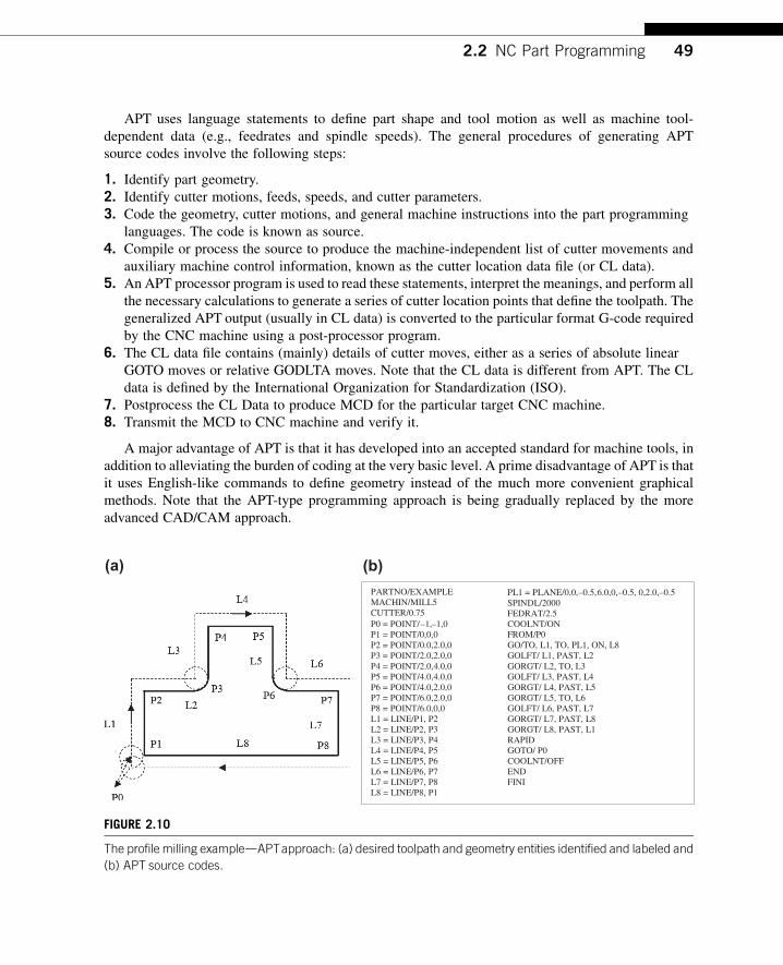
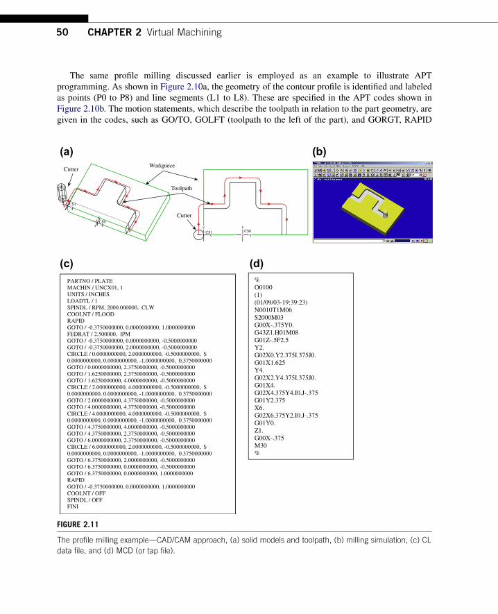
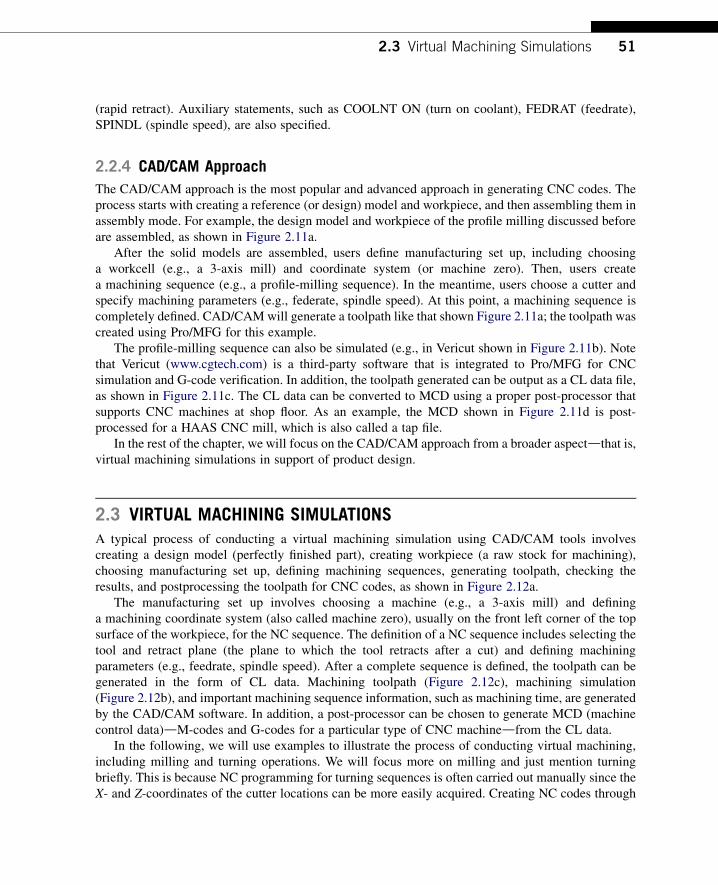

(c)
Post-Processing
Create Design Model
Create Workpiece
Define Manufacturing Setup
Define Machining Sequences
Generate the Toolpath
Check Results
(d)
Workpiece
Drive Surface
Tool Containment Rectangle
(a) (b)
FIGURE 212
Virtual machining (a) a typical process (b) design model with workpiece (c) machining toolpath and
(d) machining simulation
52 CHAPTER 2 Virtual Machining
virtual machining is sometimes overkill However from a design perspective it is essential thatdesigners incorporate all NC operations when addressing manufacturability of the product includingdetecting potential manufacturing-related issues and coming up with an overall machining timeestimate for design trade-off if necessary
231 Basic Machining Simulations
Basic machining operations refer to milling sequences involving simple geometric features such asprofile milling hole-making pocket milling and so on These basic sequences can be performed usinga standard 3-axis mill
For a full-scale CADCAM system such as ProMFG or CAMWorks users will have to create 3Dsolid parts for the design model (and usually workpiece as well) in order to proceed For software toolsof CAM emphasis such as Mastercam a simple 2D wireframe is often sufficient to support basicmachining operations In this section we will use a simple example shown in Figure 213a to discussnumerous aspects of the basic machining operations This example involves profile milling pocketmilling and hole-making Figure 213b shows the toolpaths of the three NC sequences
Using a CAM software such as Mastercam a 2D wireframe that describes the geometry of theouter profile pocket and holes (Figure 213a) is sufficient for carrying out a virtual machiningoperation The size of the design model is 6 in 4 in Both corner radius and diameter of the four holesare frac34 in The radii of the large and small semicircles of the center pocket are 1 in and frac12 in
Profile (Blue)
Pocket (Blue)
Hole Drilling (Green)
Workpiece (Dotted)
(a) (b)
FIGURE 213
Basic machining sequences (a) machining simulation and (b) machining toolpaths
Design model (2D wireframe)
Workpiece (Dotted line)
Pocket (Blue)
(a) (b)
FIGURE 214
Basic machining example (a) 2D wireframe design model and (b) with workpiece in isoview
23 Virtual Machining Simulations 53
respectively A rectangular block of 6 in 4 in 075 in is added to the wireframe as a workpiece asshown in Figure 213b Note that the straight lines and the circular arcs in Figure 214a are created byentering end point locations center point locations radius and so on instead of creating solid featuresas those of CAD tools While entering the point locations a coordinate system was referred to Thiscoordinate system is implicitly defined as the reference so called the machine zero to which all CLdata of the toolpath refer
An end mill of 11 in diameter is chosen for the first NC sequence which is a profile milling (calledcontour milling in Mastercam) Some software (eg Mastercam) provides a detailed view on thegeometry of the cutter such as the one shown in Figure 215a Other software (eg ProMFG) requiresusers to enter basic parametersdfor instance cutter diameter and lengthdto define a cutter Ingeneral a cutter is represented as a cylinder in machining simulation for visual for example see thecutter of Mastercam shown in Figure 215b Note that Mastercam provides a predefined cutter library(Figure 215c) which helps users pick suitable cutters for machining In practice one will have to
FIGURE 215
Selecting a cutter (a) detailed geometry of an end mill in Mastercam (b) cutter in virtual machining simulation
and (c) prescribed tool library in Mastercam
54 CHAPTER 2 Virtual Machining
check the mechanist at the shop floor to ensure that the cutters selected for virtual machining corre-spond to those on the tool turret in the CNC machine
Several important cutting parameters are required for conducting profile milling In this examplethe (overall) depth of cut required for the profile milling is set to frac12 in Recall that the thickness of theworkpiece is frac34 in Therefore there will be a layer of frac14 in material intentionally left uncut aftercompletion of the profile pass The maximum step depth which defines how thick the cutter trimsaround the workpiece in one pass is set to frac14 in in this example Note that step depth is highly relatedto the size of the cutter among other factors In general a cutter of larger diameter has more strength toplunge deeper into the workpiece A cutter of stronger material (eg cutter of carbide inserts) allowsfor a larger step depth The rule of thumb is that the step depth has to be less than the radius of thecutter Since the (overall) depth of cut is frac12 in and the maximum step depth is frac14 in it will take twopasses for the cutter to go around the workpiece to complete the profile milling
Note that the extra stepsdlead in and lead out respectivelydwhen the cutter approaches andleaves the workpiece are often added to the profile toolpath as shown in Figure 216a Once thetoolpath is generated machining simulation can be shown like that of Figure 216b in for exampleMastercam
One practical issue that must be taken into consideration for profile milling is mounting theworkpiece to the workbench of a CNC machine Notice that in some cases the cutter may not be ableto cut a complete path around the workpiece without colliding with the clamps that hold the workpieceClamping and fixtures is an important issue in practice which will be discussed in Section 24
The second NC sequence is pocket milling For a pocket milling the cutter first plunges into theworkpiece then moves around to make a cut The cutter usually moves in one direction steps sidewayand cuts in the reverse direction The cutting pattern is similar to mowing the lawn in your backyardwhere we step sideways at the end of each pass before reversing the mowing direction This is one of
Toolpath
Lead In
Lead Out
(a) (b)
FIGURE 216
Profile milling sequence (a) toolpath and (b) milling simulation
Profile pass(a) (b) (c)
FIGURE 217
Pocket milling sequence (a) toolpath (b) milling simulation and (c) profile cut
23 Virtual Machining Simulations 55
the available scan patterns in CAM called zigzag Other scan patterns include spiral among otherswhere the cutter starts roughly from the center of the pocket and follows a spiral-like path andgradually moves outward
The amount of step sideways is called stepover It is obvious that stepover has to be less than thecutter diameter in order to make a clean cut As a rule of thumb the stepover is usually less than 80of the cutter diameter in practice After performing the scan passes another profile pass is added tomove the cutter around the wall of inner pocket boundary to clean up the remaining material along theboundary as shown in Figure 217a In this example the cutter chosen is a ⅜ in end mill in which thestep depth chosen is 16 in If we are cutting a frac12 in deep pocket it will take eight sets of complete scanand profile passes each 16 in deep to complete the pocket milling
Also in order to ensure a smooth inner pocket boundary it is a good practice to leave a thinmaterial layer around the boundary wall of the pocket and add a profile cut at the end to ensurea smoother pocket boundary similar to that of Figure 217c
The third NC sequence is hole-making There are four blind holes offrac34 in diameter at the cornersCreating virtual machining for hole-making is straightforward It is obvious that the drill you pick must
FIGURE 218
Hole-making NC sequence (a) detailed geometry of a drill in Mastercam and (b) toolpath
56 CHAPTER 2 Virtual Machining
have the same diameter as those holes or a drill of slightly smaller size with a follow-on boring orreaming operations In this case afrac34 in drill (Figure 218a) is chosen The toolpath generated is shownin Figure 218b
All three NC sequences can be easily combineddtoolpath and machining simulations can be likethose shown in Figures 213a and 213b respectively In addition the toolpath can be converted intoG-codes and M-codes as discussed earlier
232 Advanced Machining Simulations
Geometrically complex parts are commonly found in the automotive and aerospace industrieswhere molds and dies are manufactured for production The time spent to manufacture molds ordies of different sizes and complexities ranges from 1200 to 3800 hours (Sarma and Dutta 1997)Considerable time (49ndash72) is spent in contour surface milling for the design surfaces (thesurfaces to be machined) of molds and die Design changes in structural geometry due tofunctional considerations may affect manufacturing cost significantly and vice versa Amongdifferent types of machining operations contour surface milling is the most critical for mold anddie machining since surface milling directly affects the quality and accuracy of the designsurface
In practice a machining operation of a die or mold or any parts with sculpture (or freeform)surfaces involves four machining sequences First a face milling will clean up the mating surface forthe die Second sequence is usually a volume milling that removes material in the cavity at a fast speedOften a relatively large cutter is employed with a higher feedrate to remove material as fast as possiblewithout regard to surface finish Next is a local milling which is essentially a smaller-scale volumemilling that removes the remaining small chunk of material left from the previous volume millingsequence In general a smaller cutter is employed for local milling The last NC sequence is contoursurface millingda finish cut this is considered the most important machining sequence for sculpturesurfaces since the scallop height of the uncut material remaining on the machined surface determines
23 Virtual Machining Simulations 57
the surface quality of the machined part In addition a common practice suggests a small layer of stockshould remain on the surface of the cavity from volume milling and local milling in order to eliminatetool marks
Existing commercial virtual machining tools such as ProMFG CAMWorks and Mastercamsupport contour surface milling using various methods (eg isoparametric constant curvature andconstant scallop height) In this section we will assume ProMFG for machining a part of a 16 in 10 in 4 in block with a sculpture surface as shown in Figure 219a Note that the sculpture surfaceis lofted using four section sketches of respective circular arcs (Figure 219b) For this example wewill include a volume milling and a local milling assuming a 3-axis mill We will include a 5-axiscontour surface milling for finish cut The workpiece is a 16 in 10 in 4 in block Thecoordinate system CS0 at the top left corner of the workpiece as shown in Figure 219c is chosen asthe machine zero for this model
Two cutters are chosen for this example A 1 in end mill with corner radius frac14 in (Figure 220a) isselected for volume milling (ie the rough cut) Note that such a cutter is often referred to as bull millSeveral such cutters are commercially available for example a four- and two-flutes end mills is shownin Figure 220a Note that the sharp corner of an end mill is its weakest point The corner radius designof a bull mill strengthens the end mill by reducing chipping and providing longer tool life In mold
Machine zero
x
zCS0
(b)(a)
(c)
R650
R340
R684
400
1000
R803
FIGURE 219
Sculpture surface (a) solid model (b) section sketches and (c) with workpiece and machine zero
FIGURE 220
Cutters chosen for the machining operation (a) 1 in end mill with corner radius and (b) frac12 in ball cutter
FIGURE 221
Volume milling NC sequence (a) isoview and (b) end view
58 CHAPTER 2 Virtual Machining
applications both end and bull mill cutters have traditionally been used In addition to the bull milla frac12 in ball nose cutter (Figure 220b) is employed for both local milling and contour surface millingNote that a ball nose cutter tends to leave less tool marks on the machined surface thus leading toa better surface finish
For the volume milling the step depth and stepover are 05 in and 09 in respectively The scanpattern is back and forth along the longitudinal direction (x-axis of CS0) The resulting machinedsurface is shown in Figure 221 in which material remains on the surface and requires a following NCsequence for further clean up The machining time estimated by ProMFG is 37 minutes assuminga feedrate of 20 inmin Determining an adequate feedrate for a machining sequence is critical inpractice A fast feedrate will reduce overall machining time however it is subject to a possible roughsurface finish and a higher probability of cutter breakage and shorter tool life Feedrate will be dis-cussed in more detail in Section 24
FIGURE 222
Machined surface after the local milling sequence (a) ball nose cutter with stepover 04 in and step depth
02 in (b) end mill of corner radius 01 in with stepover 04 in and step depth 02 in and (c) end mill of
corner radius 01 in with stepover 04 in and step depth 005 in
23 Virtual Machining Simulations 59
For the local milling the step depth and stepover are 02 in and 04 in respectively Both aresmaller than those of volume milling This is mainly because a smaller cutter is employed Alsoa smaller feedrate 5 inmin is chosen for this sequence The scan pattern is spiral which is deter-mined by ProMFG The resulting machined surface is shown in Figure 222a in which surface issmoother but still requires further clean up and polish The machining time for the local milling isestimated by ProMFG as 137 minutes partly due to a smaller feedrate
The machined surface is certainly not acceptable for practical applications Before carrying outa contour surface milling is there any way to improve the quality of the machined surface Is thecurrent setup for local milling the best There are several possibilities that may provide a better resultFirst an end mill of the same diameter (frac12 in) but a smaller corner radius 01 in (vs frac14 in) requiresabout the same machining time Comparing with the first case shown in Figure 222a this bull millprovides a machined surface with a slightly better surfacedespecially in the area closer to the centerof the spiral pattern (Figure 222b) This is mainly due to the smaller surface curvature closer to thecenter of the spiral pattern in which a bull mill leaves less material than that of a ball nose cutter
How about step depth and stepover Which parameter will impact more to the surface quality Ingeneral it depends on the geometric shape of the design surface For a surface of high curvature
60 CHAPTER 2 Virtual Machining
a smaller step depth reduces the staircase type surface For a surface of small curvature one can affordto choose a larger stepover to reduce the machining time and yet lead to a relatively good surfacefinish Smaller stepover and smaller step depth will certainly give a better surface finish however itmay require substantially more machining time to complete the cut For example Figure 222c showsa much smoother machined surface created by using a smaller step depth 005 in in which themachining time jumps to more than 600 minutes assuming the same feedrate Note that in practiceone may increase the feedrate when a smaller stepover and step depth are employed resulting ina reduced machining time
Although surface quality is much improved spending 600 minutes for a local milling is probablytoo much Plus we will employ a contour surface milling to perform the finish cut which serves thepurpose of polishing the surface For this example we will stay with the first case (surface finish shownin Figure 222a) after completing the local milling sequence
The third NC sequence is contour surface milling for a finish cut using a 5-axis mill A step size of04 in and the same feedrate 5 inmin are chosen for this sequence As mentioned earlier there areseveral options in generating a toolpath for the contour surface milling We choose the surface isolineoption for toolpath generation where one parametric coordinate of the surface is fixed at prescribedvalues in order to generate cutter contact curves that stay right on the surface (Figure 223a) Note thatthe space between neighboring tool passes is in general less than the stepover specified More on the
Cutter
CS0x
y
CS0
r
r
Tool mark
Tool mark
(a) (b)
(c) (d)
FIGURE 223
Contour surface milling (a) toolpath for stepover 04 in (b) machined surface with stepover 04 in tool mark
visible (c) machined surface with stepover 02 in tool mark still visible and (d) machined surface with stepover
04 in and 005 in stock allowed tool mark removed
23 Virtual Machining Simulations 61
isoline option and toolpath generation will be discussed in Chapter 3 The machining time for thiscontour surface milling is estimated as 85 minutes based on a feedrate of 5 inmin Note that inpractice a higher feedrate is often employed for the final finish cut since the material remaining thesurface is usually minimum
The resulting surface by combining all three NC sequences can be seen in Figure 223b There areclear tool marks on the machined surface These marks were left from the previous sequencesmainly from the rough volume milling There are two ways to remove or minimize the tool marksFirst one may reduce the stepover for the contour surface milling A smaller stepover will lead toa surface with smaller scallop height therefore a better surface quality with less visible tool marks(Figure 223c) in which the stepover is reduced to 02 in However the machining time increasesabout twice (increased from 85 to 160 minutes) We will discuss more on the calculations of thescallop height in Chapter 3
Another approach and a better one is to specify a small layer of stock material uncut (stockallowed) while performing volume and local milling sequences The layer thickness should be slightlylarger than the desirable scallop height If such a stock material is specified in previous sequences toolmarks should be completely removed in theory With a stock material of 005 in and a smaller stepover(02 in) the machined surface does not reveal any tool marks as can be seen in Figure 223d
If combining all three NC sequences the overall machining time is about 334 minutes (37thorn 137thorn160) which is considered very good for machining such a sculpture surface
233 Turning Simulations
Part programming for turning is much simpler than that of milling This is mainly because that NCcode for turning only requires X- and Z-locations of the cutter A cutter for a turning operation onlymoves on the X-Z plane often following straight paths For example an area turning sequence thatremoves the material on the outside cylindrical and front end surfaces of a cylindrical block is shown inFigure 224 Note that when translating the toolpath to NC codes special attention may be required Ifyou are converting a toolpath created in ProMFG to HAAS CNC lathe there are several modificationsandor extra steps that need to be carried out For example the CL data output for the G02 and G03commands (circular interpolation) must use ldquoRrdquo values for radius If ldquoIrdquo or ldquoKrdquo values are presenta setting for the post-processor will need to be altered in order to force the output with ldquoRrdquo valuesAlso while selecting UNCL01P11 to postprocess the CL data for HAAS lathe this post-processordoes not output the X Z R (R is the radius of circular interpolation in G02 and G03) In additionthe post-processor does not output the F (feedrate) values with a decimal point which is required bythe HAAS controller Again a setting for the post-processor will need to be altered to output CNCcodes with correct format
Going over all the modeling and simulation work for a simple turning cut such as the areaturning shown in Figure 224b may not be the best option in terms of time and effort Plus thereare additional setups in the NC postprocess that are usually required for valid NC codes Thereforemanual coding is often more effective for the CNC lathe Even when machining a sculpture surfaceon turning operation a toolpath can be defined along a planar curve which is much easier to obtainmanually than that of milling often dealing with a surface As a result part programming forturning operations is usually carried out by collecting cutter location data on the X-Z plane andmanually composing NC programs
FIGURE 224
Area turning (a) material to be removed on the cylindrical and front end surfaces (b) turning toolpath and
(c) machined surface
62 CHAPTER 2 Virtual Machining
24 PRACTICAL ASPECTS IN CNC MACHININGSo far our discussion has been focused on virtual machiningdeverything is carried out in a virtualenvironment In a virtual environment almost anything can be set up and simulated Machiningsequences that look good on a computer do not guarantee they can be implemented physicallywithout any flaws For example a deep and narrow pocket may not be possible to cut since a smallsize cutter is usually short and will not be able to reach deep enough to the bottom of the pocketAlso for profile milling in a virtual environment a cutter moves around the outer boundary of theworkpiece without any problem In reality the workpiece must be clamped to the workbench of theCNC machine and cutter must not collide with the clamps What kind of clamp or fixture is suitablefor mounting the workpiece for a profile milling sequence
When a fixture is employed to mount the workpiece will the cutter run into the fixture Also howdoes one determine appropriate feedrate and spindle speed Which kind of cutters are suitable fora given workpiece material using selected NC sequences Most of such issues have been welladdressed in NC workbooks or machinist handbooks (eg Oberg et al 2012) We will discuss some ofthe common practical issues you may encounter in NC machining The goal of this section is toprovide you with some practical aspects in applying virtual machining to practical NC operations
24 Practical Aspects in CNC Machining 63
There are several principles you may want to consider while designing a part to be machined Theseprinciples usually lead to a part design that can bemachinedwith fewer problems First designers shouldconsider designing parts that can be made out of standard size material stock This will minimize theneed to go through additional machining sequences that cut a standard stock to the desired size Secondavoid deep pockets in parts you may not find a cutter long enough to reach the bottom of the pocketEven if you can the long cutter may deflect or break during deep pocket cutting Third keep all filletradii identical whenever possible and keep them larger than the radius of available cutters A large cutterwill not be able to cut a small fillet Fourth keep all hole sizes identical if possible and avoid odd-sizeholes As a result one or two drills are able to make all holes which minimizes the frequency for toolchange Hole sizes should in general match those of available drills Finally avoid having to cut the partfrom multiple sides if possible Certainly compromises will always have to be made when designinga new part with machining considerations However staying with the preceding principles as much aspossible will make the machining sequences more straightforward and usually less costly
In the following we will discuss three main issues (1) choice of jigs and fixtures (2) determinationof machining parameters including feedrate and spindle speed as well as cutter selection and (3)setting up NC machining In Appendix C we will use a HAAS mini-mill as an example to go overa few important steps in setting up a NC machining operation on a shop floor
241 Jigs and Fixtures
Mounting the stock material to the workbench (also called feed table) is often the most critical andtime-consuming element of part machining The stock material must be mounted in a way that all thetools are able to complete their paths without interfering with a fixture or the stock coming loose ormoving
The easiest way tomount stock is in a vise (Figure 225a) Once the vise is aligned andmounted to theworkbench the coordinate system for the part can easily be identified (more about this inAppendixC) Forcutting circular parts or placing bolt patterns at the end of shafts a self-centering 3-jaw chuck(Figure 225b) will save time Flat plate or sheet material can be clamped using the standard block anda clamp set can be used to fix generic parts to the table (Figure 225c)
When machining odd-shaped parts special jigs may have to be made It is important to be patient infastening the stock to the workbench The followings are a few examples that are employed to mountthe workpiece
(a) (b) (c)
FIGURE 225
Common jigs and fixtures (a) machinists vise (b) self-centering 3-jaw chuck and (c) block and clamp setup
(a) (b) (c)
FIGURE 226
Milling machine vise (a) plain vise (b) swivel base and (c) swivel base with vise
64 CHAPTER 2 Virtual Machining
The milling machine vise shown in Figure 226 is the most common type of workpiece-holdingdevice used on the milling machine The plain milling machine vise is used for holding a work-piece that has parallel sides The vise is bolted directly to the table using the T-slots in the machinetable (Figure 226a) The plain vise can be accompanied by a swivel base The swivel base(Figure 226b) is graduated in degrees and allows the vise to swivel in the horizontal plane The swivelbase gives the vise a greater degree of versatility (Figure 226c) but should be avoided when doingheavy rough-cutting operations because it reduces the rigidity of the setup
242 Cutters and Machining Parameters
The choice on cutters and workpiece material largely determine feedrate and spindle speed Cutters canbe grouped in two major categories high-speed steel (HSS) and carbide inserts as shown in Figure 227HSS cutters maintain hardness and strength at elevated temperature and are less expensive Two basictypes of HSS cutters are commercially available M-series (Molybdenum type) and T series (Tungstentype) M-series steels contain up to 10 molybdenum with chromium vanadium tungsten and cobaltT-series steels contain 12 to 18 tungsten with chromium vanadium and cobalt
M-series steels have generally higher abrasion resistance than T-series less distortion in heattreatment and are less expensive Carbide inserts endure high temperatures with high strength and
FIGURE 227
Cutters (a) HSS cutters and (b) carbide insert
Flat endmilld=cutter diameter
Axis of revolution
d
(a) (b)
Ball Nose CutterIf ball is not ldquoburiedrdquo in workpiece then a will be less than cutter diameter ie no cutting occurs at full tool diameter
Cutter Axis
a
Cutting edge
FIGURE 228
Cutters (a) flat endmill and (b) ball nose cutter
24 Practical Aspects in CNC Machining 65
hardness especially suitable for high-speed cutting The tungsten carbide (WC) cuts nonferrousabrasive materials and cast irons Titanium carbide (TiC) has higher wear resistance thanWC but is notas tough Titanium carbide cuts hard materials mainly steels and cast irons
From their geometric shape there are flat endmill (Figure 228a) ball nose cutter (Figure 228b)and bull mill (Figure 220a) In general endmills are suitable for face profile and pocket milling Aball nose cutter is more suitable for sculptural surface milling since there is less tendency to gougeusing a ball nose cutter
Two of the most critical machining parameters are spindle speed and feedrate Spindle speed N(rpm) is usually determined by the cutting speed V (inmin) that is
N frac14 V=ethpdTHORN (21)
where d is the cutter diameter (in) In general factors affecting the calculation of cutting speed include(1) the material being machined (steel brass tool steel plastic wood) (2) the material the cutter ismade from (carbon steel high-speed steel carbide ceramics) and (3) the economical life of the cutterthat is the cost to regrind or purchase new compared to the quantity of parts produced
You may find recommended cutting speeds in machining textbooks or handbooks for examplessee Tables 21a and 21b As shown in the tables cutting speed is provided in a large range This isbecause there are other factors to consider while determining cutting speed (eg type of the millingsequences) A rough cut usually requires a larger cutting speed thus a higher spindle speed in order toremove material fast Different data sources may offer cutting speeds that differ by sometimessignificant amounts Numbers obtained from machining handbooks are a good starting point You mayhave to make needed adjustments onsite
Once an adequate spindle speed is determined a feedrate f (inmin) can be calculated using thefollowing equation
f frac14 ft N n (22)
where n is the number of teeth on the cutter and ft is the feed per tooth (in) as depicted in Figure 229Factors that affect the feedrate include (1) type of tool (eg a small drill vs a large end mill) (2)surface finish desired (3) power available at the spindle (to prevent stalling of the cutter or workpiece)
Table 21 Recommended Cutting Speeds
(a) Recommended by Kalpakjian and Schmid (2010)
Workpiece Material
Cutting Speed (ms)
HSS Carbide Inserts
Aluminum Alloys 15 w 6 10 thornMagnesium Alloys 3 w 5 12 thornCopper Alloys 03 w 15 15 w 7
Steels 01 w 07 05 w 4
Stainless Steels 02 w 1 1 w 2
High-Temp Alloys 005 w 01 02 w 03
Titanium Alloys 01 w 1 05 w 2
Cast Irons 02 w 06 05 w 2
(b) Recommended by Krar et al (2010)
Workpiece Material
Cutting Speed (mmin)
HSS Carbide Inserts
Machine Steel 21 w 30 45 w 75
Tool Steel 18 w 20 40 w 60
Cast Iron 15 w 25 40 w 60
Bronze 20 w 35 60 w 120
Aluminum 150 w 300 300 w 600
ftV
Rack angle
Relief angle
FIGURE 229
Feed per tooth
66 CHAPTER 2 Virtual Machining
(4) rigidity of the machine and tooling setup (ability to withstand vibration or chatter) (5) strength ofthe workpiece (high feedrates will collapse thin-wall tubing) and (6) characteristics of the materialbeing cut (eg chip flow depends on material type and feedrate)
The recommended feed per tooth for high-speed steel and carbide inserts are listed in Table 22aand 22b respectively As shown higher feed per tooth is recommended for carbide insert cutters whilecutting hard materials such as steels Also higher feed per tooth is recommended for face milling thanend milling This is because more teeth are in contact with the workpiece in face milling thus a higher
Table 22 Recommended Feed per Tooth by Krar et al (2010)
(a) High-speed steel
Workpiece Material
Face Mills End Mills
in mm in mm
Aluminum 0002 055 0011 028
Brass and bronze 0014 035 0007 018
Cast Iron 0013 033 0007 018
Bronze 0012 030 0006 015
Tool steel 0010 025 0005 013
Stainless steel 0006 015 0003 008
(b) Carbide inserts
Workpiece Material
Face Mills End Mills
in mm in mm
Aluminum 0020 050 0010 025
Brass and bronze 0012 030 0006 015
Cast Iron 0016 040 0008 020
Bronze 0012 040 0008 020
Tool steel 0014 035 0007 018
Stainless steel 0010 025 0005 013
24 Practical Aspects in CNC Machining 67
feedrate While carrying out finish cut the feedrate can be turned up if material remaining is minimalAgain numbers obtained from machining handbooks only provide a good starting point
243 Setting a CNC Sequence
In this subsection wewill go over a few important points in setting up an NCmachining sequence at theshop floor These are the things that one must be aware of when anNC program is generated and is readyto carry out the machining sequence using a CNC machine Since there are wide varieties of machineswewill only discuss two key stepswithout referring to specificmachines The goal here is to provide youwith some ideas when bringing the part program to a CNCmill and to serve as a reminder that there arepractical issues to go over before a successful machining sequence can be carried out on the shop floorWe use aHAASmini-mill as an example to illustratemore detailed procedures and setups inAppendixCfor those who are interested in learning more or those who have access to a HAAS mill
After a workpiece is loaded and secured on the workbench two key steps are followed loading andsetting up tools and setting up work coordinate and machine zero
Loading cutters is one of the most important steps in setting a CNC machining sequence You maycollect all the needed cutters and follow the machine instructions to load them to the mill Once alltools are loaded into the tool changer the lengths of each must be measured You will also need tomeasure cutter diameters if tool radius compensations are included in your NC codes Before
FIGURE 230
Using edge finder to set up X-axis
68 CHAPTER 2 Virtual Machining
measuring lengths we first place a work coordinate (or machine zero) on the stock material in the sameplace that you have set it in CAM software (such as ProMFG or Mastercam) Machine zero is usuallyplaced at the front left corner of the top surface of the stock Usually we load a drill chuck with an edgefinding tool (Figure 230) into the spindle move the edge finder to the X position of the part using thejog handle and zero the X-axis We repeat the similar steps for setting up Y-axis
The Z-axis will be set after all the tools needed for machining are loaded Often the first cutter isadvanced into the spindle Then we position the tool tip over the top of the X and Y-zero We lower thetool and place a feeler gage (Figure 231) to set zero for Z-axis Since the Z axis is zeroed using the first
FIGURE 231
Z-axis offset and tool length offset
25 Commercial Machining Simulation Software 69
tool the length offset for tool one should be zero The thickness of the feeler gage must now besubtracted from the Z axis height The same steps will have to be repeated to measure or offset the toollengths for all cutters loaded
Once these two steps are completed you are ready to load the program to the machine Usuallya CNC mill is networked with a PC In that case an NC program can be loaded to the mill very easilyOnce a program is loaded it usually automatically becomes the selected program the mill will run It isa good practice to verify the toolpath on the monitor screen of the mill like that shown in Figure 29bbefore running the program
25 COMMERCIAL MACHINING SIMULATION SOFTWAREA large number of commercial CAM software tools can currently be obtained There is general-purpose CAM software that supports turning and milling sequences There are also special-purposecodes that focus on narrow tasks (eg software for creating a toolpath only for engraving)
General-purpose software offers adequate geometric modeling capabilities Most of them aretightly integrated with an existing CAD system Roughly the general-purpose CAM software can becategorized into three main groups in terms of how they relate to a CAD system The first groupincludes CAM as one of the modules in a CAD system such as ProMFG of ProENGINEER CAMmodule of CATIA CADCAMCAE system and CAM module of the NX Unigraphics The secondgroup refers to CAM as third-party software that is seamlessly integrated into commercial CADsoftware This includes CAMWorks (wwwcamworkscom) integrated with SolidWorks Inventor-CAM (wwwinventorcamcom) with Autodesk Inventor and so on The third group includes stand-alone CAM software that is not associated with any CAD systems (eg Mastercam SurfCAM (wwwsurfwarecom) and GibbsCAM (wwwgibbscamcom))
Special-purpose codes as mentioned earlier focus on narrow tasks Some of these codes includeArtCAM (wwwartcamcom) that supports sign makers woodworkers engravers and jewelers todesign and manufacture 3D or 2D products from their artwork
This section presents a brief overview on the commercially available CAM software We willinclude a short description for one or two of the software from each group The strength weaknesspros and cons of these codes will be briefly discussed
251 General-Purpose Machining Software
Major CAD systems such as ProENGINEER CATIA and NX are equipped with a CAM modulethat is part of the CAD and is seamlessly integrated with the respective CAD systems As mentionedbefore other major CAD systems (eg SolidWorks or AutoDesk) offer a CAM module that isdeveloped by a third party and is seamlessly integrated with the CAD systems as well All such CAMmodules provide excellent virtual machining capabilities in support of a broad range of machiningsequences including profile milling volume milling surface milling hole-making text-engravingand so on These capabilities support users to create virtual machining simulation generate a toolpathand convert the toolpath into CNC codes following the steps depicted in Figure 212a Development ofsoftware in this category essentially started with CAD and then extended to include CAM eitherthrough its own development and acquisition or via a third party
70 CHAPTER 2 Virtual Machining
The major advantage of these software tools is that they require a relatively short learning curve fornew CAM users This is mainly because the user is already familiar with the basic operations andprocedures of using the CAD portion of the software Learning CAM that is a built-in module ofa CAD system the user is familiar with is relatively straightforward However using CAD-centeredCAM module users must start with creating 3D solid models that represent design and workpieceeven for a simple cut such as hole drilling
One thing worth noting is that CAMWorks offers a knowledge base and Automatic FeatureRecognition (AFR) tools to help users in the machining processes The AFR technology analyzes solidmodel geometry and identifies machineable features (eg holes slots pockets and bosses) Theknowledge base is a self-populating database that contains information about the cutting tools andthe parameters used by the operator as well as information regarding the cutting tools available on theshop floor This database helps store the best practices at a centralized location in the tool room
On the other hand software such as Mastercam SurfCAM and GibbsCAM (all general-purposeCAM software) were developed and marketed with the sole purpose of supporting virtual machiningwhich is essentially CAM-centered These tools offer excellent capabilities for virtual machiningoften even more general and versatile than those integrated in CAD systems For example Mastercamprovides more options for generating a toolpath for contour surface milling including the constantscallop height option that was not available in ProMFG
In general virtual machining can be carried out with these tools using wireframe surface orsolid geometric entities For example a pocket milling or a profile milling only requires a simplewireframe sketch that describes the geometry of the pocket and profile boundary of the part This ismuch simpler and requires less effort compared with that of using a CAD-centered CAM moduleHowever none of the geometric entities created in such tools are parametric which are not suitablefor design changes They are created using points lines and patches as well as basic extrusionsweep and rotate operations Modeling capabilities in CAM-centered software are in general inferiorto those in CAD
252 Special-Purpose Machining Software
Special-purpose software offers toolpath generation for narrow tasks Some of these codes includeArtCAM and DeskCNC among many others These software tools are very much tailored for specificmachining tasks in narrow applications
ArtCAM supports sign makers woodworkers engravers and jewelers who design and manufac-ture 3D or 2D products from their artwork Users can create highly intricate personalized or custom 3Dmodels from 2D sketches or photographs The software guides users through the entire process fromconceptual sketch to the finished piece or mold An example of The Black Bull sign-making inArtCAM is shown in Figure 232a for reference
DeskCNC is another popular code for engraving The tool supports users to bring in drawingsphotographs or any other computer graphic image and convert it into a DXF file or into G-Code readyto be machined Screen captures in Figure 232b show the process of converting an image into theactual toolpath used in creating the finished engraving The original file is loaded into DeskCNC andconverted andor processed into a grayscale image by numerous available graphics filters Once theimage is processed DeskCNC converts the picture files directly into toolpaths for an engravingmachine
FIGURE 232
Examples of special-purpose software (a) ldquoThe Black Bullrdquo sign making in ArtCAM (wwwartcamcomvideos
2011-online-demo-catchuphtml) and (b) the process of converting an image into the actual toolpaths using
DeskCNC (wwwdeskamcomdeskarthtml)
25 Commercial Machining Simulation Software 71
Another special-purpose code worth-mentioning is CNCezPRO It is a real-time 3D simulator forCNC toolpath verification equipped with good real-time rendering and 3D visualization of tool cutsUsers are able to write edit and revise G- and M-codes and visualize the toolpath in real time Forexample a trajectory milling (or slot milling) on XZ (G18) and YZ (G19) planes can be generated andsimulated in CNCezPRO as shown in Figure 233a In addition a user-defined post-processor forcustomized G- and M-codes and a macro language for custom cycles make CNCezPRO a powerfultool-proving package for any shop Other similar software includes CNC Simulator (see Figure 233b)CutViewer (wwwcutviewercom) AutoEditNC (wwwbetatechnicalcomautonchtm) and CIMCOEdit (wwwcimcocom)
FIGURE 233
Examples of special-purpose software for manual CNC programming and toolpath verification (a) a trajectory
milling in CNCezPRO (wwwcncezprocom) and (b) pocket and profile milling using CNC Simulator (www
cncsimulatorcom)
72 CHAPTER 2 Virtual Machining
26 CASE STUDY AND TUTORIAL EXAMPLESIn this section we will present a case study where virtual machining is conducted for machining diesthat cast tracked vehicle roadarms In addition to virtual machining this case involves mold designusing ProMOLD a software module of ProENGINEER that supports mold design in a computer Thepurpose of presenting this case study is to demonstrate that virtual machining is applicable to practicalengineering applications in industry In addition tutorial examples including a name plate andsculpture surface machining will be discussed Step-by-step instructions for creating these tutorialexamples are given in tutorial M4 S4 and P4 at the end of this book
261 Case Study
Virtual manufacturing is applied to develop and simulate the manufacturing process for tooling thatcast tracked vehicle roadarms The die-casting process is assumed for fabricating green parts of theroadarm which involves design and machining of the cover and ejector dies The machined dies canthen be used to die cast the green parts of the roadarm Most die castings are made from non-ferrousmetals specifically zinc copper aluminum magnesium lead pewter and tin based alloys We assumethat the roadarms are made from aluminum which is light weight with high strength The schematicillustration of the manufacturing process is given in Figure 234 As shown in the figure die castingproduces two parts per operation in this design Volume milling and drilling are used to machine thegreen part for the final roadarms by removing extra material that remains in the spruce and runners aswell as drilling holes at each end
Two dies cover and ejector are designed using ProMOLD A sprue which is a countersink hole iscreated on the top face of the cover die as shown in Figure 235a Circular shape runners are createdbetween the cover and ejector dies In addition waterlines are created in both dies for coolingpurposes as shown in Figure 235a
The machining operations of the dies involve volume milling that removes most of the cavitymaterial (plus sprue and runners) local milling that cleans up material left from the volume milling
Cover die
Ejector die Green part
Machined parts
Remaining material
Cover die
Ejector die
Sprue
Waterlines
Runner
(a) (b) (c)
FIGURE 234
Schematic illustration of roadarm manufacturing process (a) mold design (b) explode view and (c) machined
parts
Waterlines
Runners Cavity
Spruce Waterlines
Runners Cavity Top
Face
(a) (b)
FIGURE 235
Design of cover and ejector dies (a) cover die and (b) ejector die
Table 23 Cutters Used for Volume Milling
NC 1 NC 2
Length 3 in 3 in
Diameter 1 in 025 in
Round 01 in 01 in
Table 24 Manufacturing Parameters for Volume Milling
NC 1 NC 2
Cut Feed 10 inmin 10 inmin
Step Depth 05 in 01 in
Stepover 07 in 02 in
Spindle speed 2000 rpm 2000 rpm
Machining Time 92 minutes 587 minutes
26 Case Study and Tutorial Examples 73
contour surface milling that further cleans up the cavity surface grinding that polishes the cavitysurface by removing the leftover scallops and hole drilling for the waterlines Hot work H13 die steelis selected as the material for the die workpiece For illustration purposes only volume milling andcontour surface milling performed on the cover die are shown To begin the machining operation forthe cover die a workpiece of 8 in 525 in 2 in rectangular block is first created
A 3-axis mill is assumed for performing two NC sequences of volume milling The first sequenceremoves the top thin layer of the workpiece to generate a smooth surface The thin layer thickness is0125 in The second volume milling cuts the cavity and runners Cutters and machining parameters ofthe NC sequences are listed in Tables 23 and 24 respectively As shown in Table 24 the machiningtimes of the two NC sequences are 92 and 587 minutes respectively
FIGURE 236
NC sequence 1 of volume milling (a) milling simulation and (b) toolpath
FIGURE 237
NC sequence 2 of volume milling (a) milling simulation and (b) toolpath
74 CHAPTER 2 Virtual Machining
Simulation of these two NC sequences in ProMFG is illustrated in Figures 236 and 237respectively The first sequence creates a smooth flat surface The second sequence cuts the cavity butgenerates stair case type surface which is not smooth Note that the distance between the stair layers iscontrolled by the step depth manufacturing parameter which is 01 in in this case The cavity surfacemust be machined again using contour surface milling for a smoother surface This will minimize thegrinding operation
A 3-axis mill is assumed for performing the contour surface milling Note that five-axis millusually produces better surface smoothness for contour surface milling The cutter of length 2 indiameter 025 in and round radius 0125 in is used for the contour milling The machining parametersare summarized in Table 25
Table 25 Manufacturing Parameters for Contour Surface Milling
Contour Surface Milling
Cut Feed 10 inmin
Stepover 025 in
Spindle Speed 2000 rpm
Machining Time 359 minutes
FIGURE 238
NC sequence of contour surface milling (a) milling simulation and (b) toolpath
26 Case Study and Tutorial Examples 75
The contour surface milling simulation is performed as shown in Figure 238a The toolpath of themachining operation is shown in Figure 238b The total machining time is estimated as 359 minutesNote that the cavity surface is still not smooth The scallop remaining on the cavity surface can bereduced by using a smaller stepover and manufacturing time will increase Grinding operations areoften employed to polish the cavity surface which is not simulated
Virtual Machining for Green PartWith the dies fabricated the die-casting process can be carried out Assuming the casting process hasbeen performed the roadarm green part shown in Figure 234b is obtained The volume milling isperformedfirst to remove the extramaterial remaining in the runners and sprue then to create holes in theroadarm Using the roadarm green part as the workpiece the 3-axis milling machine is again selected
The volume milling simulation for the center hole is presented as shown in Figure 239a Themachining time for thevolumemilling is found to be29minutes and the toolpath is shown inFigure239b
Using the preceding virtual manufacturing process the manufacturability of the optimal roadarmcan be verified In addition to the simulation and machining time estimate ProMFG generates cutter
FIGURE 239
Volume milling operation for the middle hole (a) milling simulation and (b) toolpath
76 CHAPTER 2 Virtual Machining
location data that can be converted into G-code and M-code for CNC using a proper post-processorCertainly special fixtures must be design and fabricated to support the machining sequences of thegreen part and cutting the hole of the roadarm
262 Tutorial Examples
A name plate and a sculpture surface example are included in the tutorial lessons This name plateexample involves profile and volume millings and is presented so that you may learn to use ProMFG
EXAMPLE 21 NAME PLATEThis tutorial example involves designing and creating a toolpath for machining a customized name plate ona 3 in 12 in ⅜ in workpiece using both ProMFG and Mastercam
Two NC sequences volume milling and engraving are created using ProMFG Nine letters ldquoName Platerdquoaresketched on the top surface of the rectangular block and extruded 18 in into the block as a cut feature as shown inFigure 240a Note that a CG Triumvirate Inserat font is chosen for the alphabets You may draw a spline curve andchoose ldquoPlace Along Curverdquo to place the text along the curve (see Figure 240b)
A 18 in end mill is picked to make the cut As shown in the machining simulation this small cutter is able toreach most pocket areas to make cuts except the narrow area (eg the narrow cross line in the letter N) and sharpcorner In general the toolpath generated for volume milling is acceptable
Note that in creating a volume milling sequence using ProMFG users will have to create a ldquomill volumerdquo whichdefines the portion of the workpiece to be removed In using ProMFG creating a mill volume involves makinga sketch extruding the sketch for a solid block and intersecting the block with the design model to generate a trimsolid feature that represets exactly the material to be removed For some intricate surfaces ProMFGmay not be ableto process the trim function
The toolpath for the engraving sequence in this example is created using a Groove feature in ProENGINEER Asshown in Figure 240d six lettersdldquoGrooverdquodin an outline style are defined in the design model The same cutterwith a step depth 18 in is chosen for the engraving NC sequence Note that the text engraved will have the samesize as the cutter (18 in) that is the cutter will move one pass along the outer profile of individual letters
A similar name plate design is created for Mastercam as shown in Figure 241a The MC9 font is chosen tocreate the ldquoMASTERCAMrdquo text Note that a simple 2D wireframe sketch is sufficient for this machining simulationthere is no need to create 3D solid models Two sequences are created a profile milling that cuts along the outerboundary of the workpiece and a volume milling that cuts the area between the inner boundary curve and the outerprofile of individual letters A 18 in end mill with a step depth of 18 in is picked to make the cut The toolpath(profile milling and volume milling combined) and machining simulation are shown in Figures 241b and 241crespectively
FIGURE 240
CNC sequences for machining a name plate using ProMFG (a) creating text for volume milling (b) adding
a spline (c) machining simulation in Vericut and (d) adding text for an engraving sequence
10
10
05 02
(a)
(b) (c)
FIGURE 241
Volume CNC sequences for machining a name plate using Mastercam (a) creating text for volume milling
(b) combined toolpath and (c) machining simulation
26 Case Study and Tutorial Examples 77
andor Mastercam in projects P4 and M4 respectively In addition after going through this simpleexample you should see the major differences between the two software tools and hopefully be able toidentify a few pros and cons of each Once you are more familiar with one of these two software toolsyou may move to the second tutorial exampledblock with a sculpture surfacedin which both rough
78 CHAPTER 2 Virtual Machining
and finish cuts are required Three CAM software ProMFG Mastercam and CAMWorks areemployed for this example Since some information about this example has been discussed in Section23 using ProMFG we will focus more on Mastercam Machining the block using CAMWorks isdiscussed in Tutorial S445 This example should help you become more familiar with ProMFGMastercam andor CAMWorks
EXAMPLE 22 BLOCK WITH A SCULPTURE SURFACENC sequences for machining the sculpture surface of the block example discussed in Section 23 is chosen as thesecond tutorial example As discussed in Section 23 three NC sequencesdvolume milling local milling andcontour surface millingdwere employed for machining the surface using ProMFG This example focuses on usingMastercam to create a similar machining simulation
We will create three sequences using Mastercamdsurface rough flowline rough-restmill and surface finishdwhich correspond to volume milling local milling and contour surface milling in ProMFG Since creating thesculpture surface by blending circular arcs on four parallel planes using Mastercam is more time consuming we willimport the ProENGINEER part of the block into Mastercam Mastercam supports model import directly from ProENGINEER in addition to other CAD systems (eg SolidWorks CATIA and AutoDesk)
The ProENGINEER part will be imported into Mastercam in a default position and orientation similar to that ofFigure 242a The imported geometric entities usually must be rotated and translated to a proper position andorientation (similar to those shown in Figures 242b and 242c) so that the machine zero coincides and aligns withthe coordinate system built in Mastercam
A surface rough flowline with a 1 in bull mill of frac14 in corner radius was chosen for the rough cutFlowline is one of the several options available in Mastercam Flowline cuts single or multiple surfacesusing their natural shape to define the toolpath Stepover and step depth are 04 in and 02 inrespectively These parameters are identical to those defined in ProMFG A flowline direction along
FIGURE 242
Adjusting position and orientation for the imported part (a) default position and orientation (b) rotate 90 alongX-axis and (c) rotate 90 along Z-axis and then translate 4 units along the Z-axis
(a) (b)
(c)
FIGURE 243
Surface rough flowline machining in Mastercam (a) flowline direction (b) toolpath and (c) machining
simulation
26 Case Study and Tutorial Examples 79
the short edge of the surface (Figure 243a) is chosen The resulting toolpath and machining simulationare shown in Figure 243b and 243c respectively
As can be seen in Figure 243b Rough Flowline does a similar cut to that of volume milling inProMFG Mastercam does not require defining mill volume as that of ProMFG and requires fewersteps to generate a similar toolpath
The next sequence is Rough-Restmill which removes remaining materials from the previousrough cut Rough-Restmill is very similar to local milling in ProMFG The same frac12 in ball-nose cutter and the same stepover and maximum step depth are chosen to perform thissequence The resulting toolpath and machining simulation are shown in Figure 244a and244b respectively Note that the restmill toolpath follows a spiral pattern similar to that of ProMFG
The third and final sequence is finish cut A finish-scallop and the same frac12 in ball-nosecutter are chosen The finish-scallop option generates finishing toolpaths that have consistentscallop heights over the entire set of surfaces which is a desired option to perform a finish cutA maximum stepover 005 in is specified for this sequence Note that a similar option is notavailable in ProMFG The resulting toolpath and machining simulation are shown inFigure 245a and 245b respectively As shown in Figure 245b the surface looks fairly smooth
(a) (b)
FIGURE 244
Surface rough restmill machining in Mastercam (a) toolpath and (b) machining simulation
(a) (b)
FIGURE 245
Surface finish-scallop machining in Mastercam (a) toolpath and (b) machining simulation
80 CHAPTER 2 Virtual Machining
This is because a very small maximum stepover (005 in) is specified for the finish cut Asa result the overall machining time estimated is 7 hours and 18 minutes as reported byMastercam
27 SUMMARYIn this chapter we discussed the subject of virtual machining including NC part programming virtualmachining simulations simulation software that is commercially available as well as a case study andtutorial examples In addition we briefly addressed the practical aspects in CNC machining includingjigs and fixtures cutters and machining parameters and steps in operating HAAS mini-mill We hopethis chapter has helped you become more familiar with the subject With more practice you shouldbecome more confident and competent in using virtual machining simulation tools to address the
Questions and exercises 81
manufacturability of the product and obtain reasonable machining time estimates and required setup tosupport product design
In the next chapter we will introduce the topic of toolpath generation which is the backbone ofvirtual machining simulation It should provide you with a more in-depth understanding on the factorsthat contribute to the CNC toolpath generated in virtual machining simulation For those who areconducting research relevant to virtual machining or toolpath generation Chapter 3 should serve wellas an introductory article for understanding toolpath generation For practicing engineers the chapteroffers behind-the-scene operations in the calculation of cutter location data and parameters that affectthat data Knowledge acquired will help you diagnose problems encountered on the machined surfaces(eg gaging)
In the remaining chapters of this book we will describe other pertinent technology that supportsaddressing the manufacturing issues from design perspectives including sheet forming simulation(Chapter 4) rapid prototyping (Chapter 5) and manufacturing cost estimates (Chapter 6) CNCmachining discussed in this chapter and rapid prototyping in Chapter 5 offer a means to support fastprototyping in product development These chapters should provide you with a very good under-standing on the essential topics involved in product manufacturing using advanced computer-aidedtechnology
QUESTIONS AND EXERCISES
21 Write a CNC program (with explanations for each block) for a HAAS mill to machine a 4 in
425 in 25 in aluminum block for the part (design model) shown in the following image andtable Choose your own cutters (from those shown in the table) and cutting parameters (step depthand stepover) with ldquocommon senserdquo Note that you need to use tool radius compensation for alltoolpaths Calculate the overall cutting time
Size (inches) Type Length (inches)18 Ball-nose 0375 316 Ball-nose 1000 14 Ball-nose 0625 12 Ball-nose 2000 18 Flat-end 0375 316 Flat-end 0475 14 Flat-end 0500 14 Flat-end 0875 516 Flat-end 0600 38 Flat-end 0600 12 Flat-end 1000 12 Flat-end 1500
22 Verify your NC program of 21 using an adequate software tool Search and find a softwareprogram that takes your NC program and simulates the NC sequence
82 CHAPTER 2 Virtual Machining
23 Write a NC program to cut a 025 in-deep pocket on a 3 in 3 in 05 in block shown in thefollowing figure The cutter diameter is 05 in Note that the cutter will cut inside of the pocket bymoving along the pocket boundary only one time which will leave some material uncut Youmust use tool radius compensation for the NC codes Identify the uncut area Also sketch yourtoolpath which must start from point A
Point A
B
24 Write a complete APT (Automatically Programmed Tools) program to cut a 025 in-deep pocketon a 3 in 3 in 05 in block shown in the following figure The cutter diameter is 075 in Notethat spindle speed is 580 and feedrate is 23 Note that the cutter must start from point SP andreturn to SP after the cut
P1
SP
P4 P3
P2
L3
L1
L2 L4
25 Use ProMFG CAMWorks or Mastercam (or other CAM software you have access) to machinethe design model shown below (left) from a workpiece of 12 in8 in45 in (show below right)Note that at least two NC sequences are needed face milling that removes top layer of 05 in deepfrom top surface of the workpiece then pocket milling that cuts the pocket
Questions and exercises 83
26 Design and machine a nameplate on a 3 in12 in ⅜ in Plexiglas workpiece using theHAAS CNC mill (or other mill you have access) Note that you can design your plateusing ProMFG (CAMWorks or Mastercam) directly write your CNC codes using HAAScommands or any other software tools that you found This will be a combination of textengraving volume and trajectory milling and picturelogo carving The following is whatyou need to submit for grade Please BE VERY CREATIVE(a) Your design describe it briefly in a few sentences and use pictures for illustration(b) Your CNC codes with explanations (only important blocks no need to submit the entire NC
program)(c) Final machined nameplate (if applicable)(d) Two significant things that you learned from using the mill
ReferencesChang T-C Wysk RA Wang H-P 1998 Computer-Aided Manufacturing second ed Prentice HallKalpakjian S Schmid SR 2010 Manufacturing Engineering and Technology sixth ed Prentice HallKrar S Gill A Smid P 2010 Technology of Machine Tools seventh ed McGraw-HillOberg E Jones F Horton H Ryffel H McCauley C 2012 Machineryrsquos Handbook twentyninth ed
Industrial PressSarma R Dutta D 1997 An integrated system for NC machining of multi-patch surfaces Computer-Aided
Design 29 (11) 741ndash749Smid P 2000 CNC Programming Handbook second ed Industrial Press Inc 200 Madison Avenue New York
NY 10016-4078
84 CHAPTER 2 Virtual Machining
APPENDIX A SAMPLE ADDRESS CODES
A Fourth-axis rotary motion The A address character is used to specify motion forthe optional fourth A axis It specifies an angle indegrees for the rotary axis It is always followed bya signed number and up to three fractional decimalpositions
B Fifth-axis rotary motion The B address character is used to specify motion forthe optional fifth B axis It specifies an angle indegrees or the rotary axis It is always followed bya signed number and up to three fractional decimalpositions
C Auxiliary external rotary axis The C address character is used to specify motion forthe optional external sixth C axis It specifies an anglein degrees for the rotary axis It is always followed bya signed number and up to three fractional decimalpositions
D Tool diameter selection The D address character is used to select the tooldiameter or radius used for cutter compensation
F Feedrate The F address character is used to select the feedrateapplied to any interpolation functions including pocketmilling and canned cycles
G Preparatory functions (G-codes) The G address character is used to specify the type ofoperation to occur in a block
H Tool length offset selection The H address character is used to select the tool lengthoffset entry from the offsetrsquos memory
I J K Canned cycle and circular optionaldata
The I J and K address character is used to specify dataused for some canned cycles and circular motions
L Loop count for repeated cycles The L address character is used to specify a repetitioncount for some canned cycles and auxiliary functions
M Code miscellaneous functions The M address character is used to specify an M-codefor a block These codes are used to controlmiscellaneous machine functions
N Number of block The N address character is entirely optional It can beused to identify or number each block of a program
R Canned cycle and circular optionaldata
The R address character is used in canned cycles andcircular interpolation
S Spindle speed command The S address character is used to specify the spindlespeed
T Tool selection code The T address character is used to select the tool for thenext tool change
X Y Z Linear X- Y- and Z-axis motions The X- Y- and Z-address characters are usedto specify motion for the X-axis It specifiesa position or distance along the X- Y- and Z-axesrespectively
Appendix B Sample G- and M-Codes 85
APPENDIX B SAMPLE G- AND M-CODES
G-Code Function
G00 Rapid Motion
G01 Linear Interpolation Motion
G02 CW Interpolation Motion
G03 CCW Interpolation Motion
G04 Dwell
G12 CW Circular Pocket Milling
G13 CCW Circular Pocket Milling
G17 XY Plane Selection
G18 ZX Plane Selection
G19 YZ Plane Selection
G20 Select Inches
G21 Select Metric
G28 Return to Reference Point
G29 Return From Reference Point
G40 Cutter Comp Cancel
G41 2D Cutter Compensation Left
G42 2D Cutter Compensation Right
G43 Tool Length Compensation thornG44 Tool Length Compensation G47 Text Engraving
G49 G43G44G143 Cancel
G80 Canned Cycle Cancel
G81 Drill Canned Cycle
G82 Spot Drill Canned Cycle
G83 Normal Peck Drill Canned Cycle
G84 Tapping Canned Cycle
G85 Boring Canned Cycle
G86 BoreStop Canned Cycle
G87 BoreStopManual Retract Canned Cycle
G88 BoreDwellManual Retract Canned Cycle
G89 BoreDwell Canned Cycle
G90 Absolute
G91 Incremental
G98 Initial Point Return
G99 R Plane Return
M-Code Function
M00 Stop Program
M01 Optional Program Stop
M02 Program End
M03 Spindle Forward
M04 Spindle Reverse
M05 Spindle Stop
M06 Tool Change
M08 Coolant On
M09 Coolant Off
M30 Prog End and Rewind
M97 Local Sub-Program Call
M98 Sub Program Call
M99 Sub Program Return or Loop
86 CHAPTER 2 Virtual Machining
APPENDIX C HAAS MINI-MILLWe use a HAAS mini-mill as an example to illustrate detailed procedures and setups for those who areinterested in learning more andor those have access to a HAAS mini-mill
Basic Machine ConfigurationThe HAAS mini-mill is a 3-axis mill with a work envelop 16 in 12 in 10 in as shown inFigure 246 The maximum spindle speed and rapid feed are 6000 rpm and 600 ipm (inmin)respectively There are 10 tool changers in the tool pocket (or tool turret) which are able to hold 10
(b)(a)
Jig table
Tool Pockets
Spindle
Coolant tube
FIGURE 246
HAAS mini-mill (a) exterior and (b) interior
Appendix C HAAS Mini-Mill 87
different cutters The mini-mill is relatively less expensive and is affordable for academia and a smallshop All stock material that will be machined must be rigidly mounted to the jig table The machinistmust be aware of oversized stock material extra jig components (eg clamps and vises) andextended-length milling tools to avoid collision with the spindle
Prestart and Power-UpBefore powering up the mill there are a few things to checkdfor example coolant liquid level airpressure and so on
Power-Up
The green button at the top left corner of the control panel (Figure 247) will turn on the mill Themachine will boot up and an alarm message will appear Not to worry this is normal it simply meansthat the mill has not gone through a calibration process yet Press the ZERO RET button on the controlpanel then the AUTO ALL AXES button to calibrate the machine Make sure the millrsquos door is closedThe table will move to the nearest left corner with the spindle retracted to the highest point Themachine is now powered up and ready for user control
The HAAS mill uses six modes of operation to complete the tasks needed for milling a part theyare circled in Figure 247 (left most column) The user must enter one of these modes in order to useany of the four action buttons to the right
Moving the Jig TableEnter the jog mode by pressing the HANDLE JOG button (Figure 247) Press the 1100 button thiswill move the table 01 inches per tick of the jog handle in the corresponding direction The user canspecify a smaller increment using the remaining action buttons
POWER ONOFF
SPINDLE LOAD
E - STOP
JOG HANDLE
FIGURE 247
HAAS mini-mill control panel with action buttons
(a) (b)
FIGURE 248
Moving the jig table (a) axis jog buttons and (b) jog handle
88 CHAPTER 2 Virtual Machining
Press the thornX or X button (Figure 248a) The buttons surrounding the JOG LOCK button are forthe user to select which axis is to be moved Rotate the jog handle (Figure 248b) in the clockwise orpositive direction to move the table right Position the table so that it will be easier to mount yourworkpiece
Tool LoadingLoading cutters is one of the most important steps in presetting a CNC machining sequence You maycollect all the needed cutters and follow the steps to load them to the mill First enter the MDI mode(Manual Data Input) (see Figure 247) Press ATC FWD or ATC REVuntil tool one is in the spindle Getthe tool to be loaded and insert it in the spindle as far as it will go Press and hold the TOOL RELEASEbutton (see Figure 249) A blast of air will shoot out of the spindle to clear any debris Push the tool upinto the spindle and release the button
FIGURE 249
Tool release and program reset
FIGURE 250
Work coordinate list
Appendix C HAAS Mini-Mill 89
Work Coordinate SetupThe work coordinate must be placed on the stock material in the same place that you have set it inProMFG or Mastercam (or other CAM software) The HAAS mini-mill has 14 different workcoordinates that can be set independently of one another (see Figure 250) The OFSET button can betoggled to view these coordinate offsets (see Figure 251) While the screen is displaying the offsets forthe coordinates use the up and down arrows in the center of the control panel to select the X-axis forthe coordinate system the user will be working in The default coordinate system is G54
Axis Part ZeroNow we are setting the machine zero (or axis part zero) using the following steps
1 Load a drill chuck with an edge-finding tool (Figure 252) into the spindle2 Enter HANDLE JOG mode (see Figure 247) Note that the display on the screen will not change3 Turn the spindle clockwise using the CW button (Figure 253)4 Move the edge finder to the X position of the part using the jog handle (Figure 254)5 Press PART ZERO SET (Figure 249) to zero the X-axis The Y-axis should now be highlighted in
the display
FIGURE 251
Display menu
FIGURE 253
Spindle and feed control
FIGURE 254
Using edge finder to setup X-axis
FIGURE 252
Feeler gage and edge finder
90 CHAPTER 2 Virtual Machining
G90 G54 G00 X0 Y0
FIGURE 255
X-Y coordinate zero check
Appendix C HAAS Mini-Mill 91
Repeat steps 3 through 5 to zero the Y-axis The Z-axis will be set after all the tools needed formilling are loaded
Z-Axis OffsetOnce all tools are loaded into the tool changer the lengths of each must be measured First the Z-axis isoffset using a feeler gage (Figure 256)
1 Advance tool 1 into the spindle by enteringMDImode and typing T1 then press theWRITE buttonin the lower right of the control panel
2 Press ATC FWD to move directly to tool 2 Be sure the part is out of the way before the tool changewhen using extended-length tools
3 Check the X- and Y-axis zero points by entering the contents of Figure 255 into MDI modeThe block G54 may be changed if the user selects a different coordinate system (eg G55 G59)
4 Close the door and press CYCLE START (Figure 248b) This will load into memorywhich coordinate system you will be using as well as move the table to the X-Y zero position
5 Position the tool over the area in which the Z offset can be measured there must be room for thefeeler gage as well (Figure 256)
6 Press OFSET and use the arrow keys to highlight the Z-axis offset under the proper coordinatesystem
7 Press PART ZERO SET (Figure 249) to zero the Z-axis
FIGURE 256
Z-axis offset and tool length offset
92 CHAPTER 2 Virtual Machining
Tool Offset MeasureThe lengths of each tool will be based on that of tool 1 Since the Z-axis is zeroed using tool 1 thelength offset for tool 1 should be zero Check this by toggling the OFSET button (Figure 251) todisplay the tool offset lengths Highlight tool 1 and press TOOL OFSET MESUR (Figure 249) thevalue should become zero
Offsetting ToolsDo the following to use the offsetting tools
1 Retract the tool using the handle jog Z-axis positive direction2 Press ATC FWD to the next tool and handle jog it down to the Z zero surface using the feeler gage3 Highlight the tool in the offset display and press TOOL OFSET MESUR (Figure 249) The value
that appears will be the difference in length of the tool in the spindle to tool 24 Repeat previous steps until all tools are measured
The thickness of the feeler gage must now be subtracted from the Z-axis height Toggle the OFSETdisplay to the work coordinate offsets Highlight the Z-axis and type in the negative of the feeler gagethickness and press WRITE
Loading a ProgramOnce a program is loaded using the following steps it automatically becomes the selected program themill will run if the cycle start button is pressed
1 Press LIST PROG (Figure 247) to start the program control mode programs are downloadeduploaded and deleted from this mode
2 Type in the program number starting with the letter ldquoOrdquo before the number3 Press WRITE4 Press RECV RS232 (Figure 247) to prepare the mill to receive a file from the connected computer5 Start the NCnetLite program on the computerrsquos desktop6 Click the green thumbs up button to connect to the mill (Figure 257)7 Click the transmit button and select the file to send The file is automatically sent after the OK
button is selected
THUMBS UP TRANSMIT
FIGURE 257
Loading NC program
Appendix C HAAS Mini-Mill 93
A program can be edited if the user enters the EDIT mode It is recommended that onlysmall changes be made in this mode due to the limited ability to verify the toolpaths after thispoint
Running a ProgramAfter doing the following steps do not increase the rapid feed until the program has verified that thefirst few cuts are correct
1 In the LIST PROG mode highlight the program to be run then press SELECT PROG (Figure 247)2 Enter the MEM mode and change the display by pressing CURNT COMDS (Figure 253)3 Reduce the rapid motion to 5 (Figure 253) and run the program by pressing CYCLE START
(Figure 248b)
If the cuts are not correct press the FEED HOLD (Figure 248b) button to stop the table feed thenpress RESET to turn off the spindle and coolant (Figure 249) Handle jog the tool out of the part andcall the shop supervisor for assistance
Once the program has completed remove the part and tools then clean the mill from any materialchips or spilled coolant
- 2 Virtual Machining
-
- 21 Introduction
- 22 NC Part Programming
-
- 221 Basics of NC Machines
- 222 Basic Concept of Part Programming
- 223 Computer-Assisted Part Programming
- 224 CADCAM Approach
-
- 23 Virtual Machining Simulations
-
- 231 Basic Machining Simulations
- 232 Advanced Machining Simulations
- 233 Turning Simulations
-
- 24 Practical Aspects in CNC Machining
-
- 241 Jigs and Fixtures
- 242 Cutters and Machining Parameters
- 243 Setting a CNC Sequence
-
- 25 Commercial Machining Simulation Software
-
- 251 General-Purpose Machining Software
- 252 Special-Purpose Machining Software
-
- 26 Case Study and Tutorial Examples
-
- 261 Case Study
- 262 Tutorial Examples
-
- 27 Summary
- Questions and Exercises
- References
- Appendix A Sample Address Codes
- Appendix B Sample G- and M-Codes
- Appendix C HAAS Mini-Mill
-
- Outline placeholder
-
- Basic Machine Configuration
- Prestart and Power-Up
-
- Power-Up
-
- Moving the Jig Table
- Tool Loading
- Work Coordinate Setup
- Axis Part Zero
- Z-Axis Offset
- Tool Offset Measure
- Offsetting Tools
- Loading a Program
- Running a Program
-
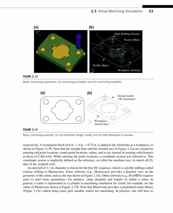
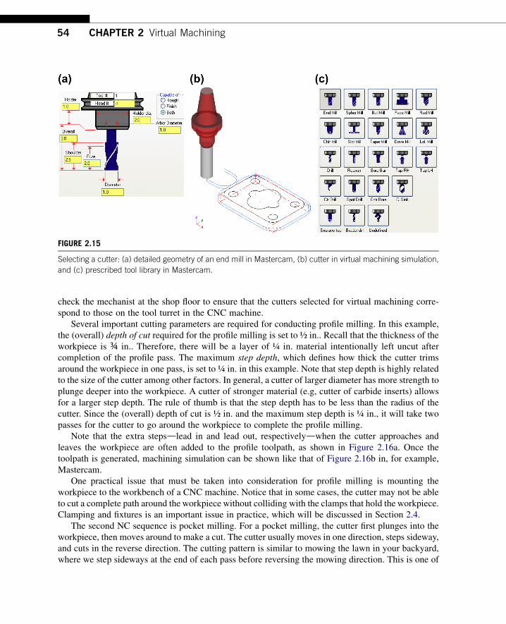
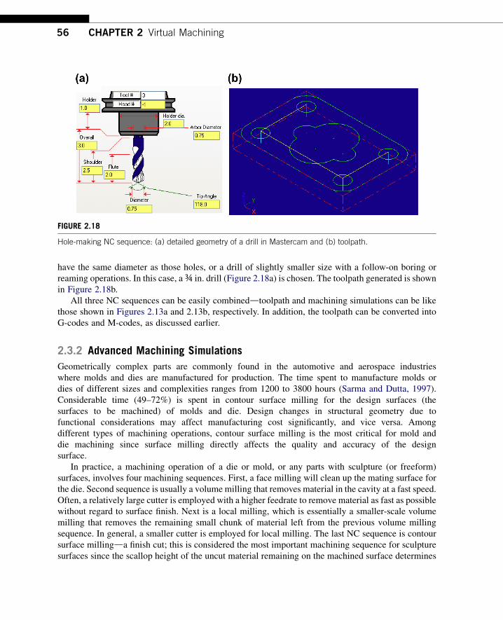
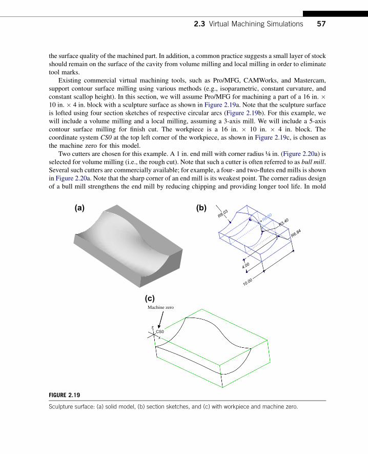
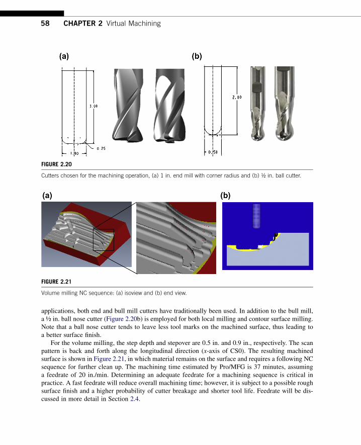
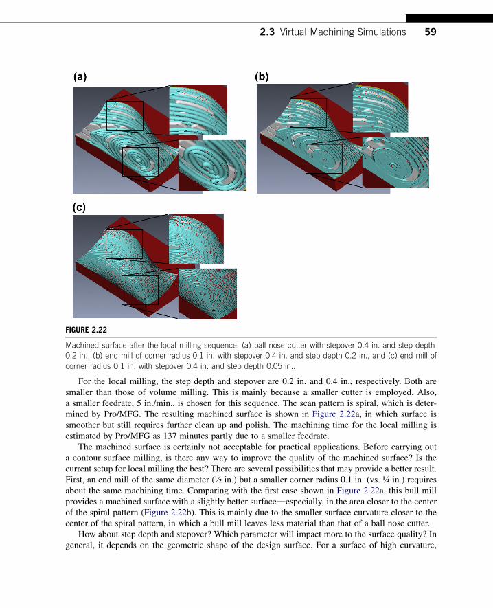
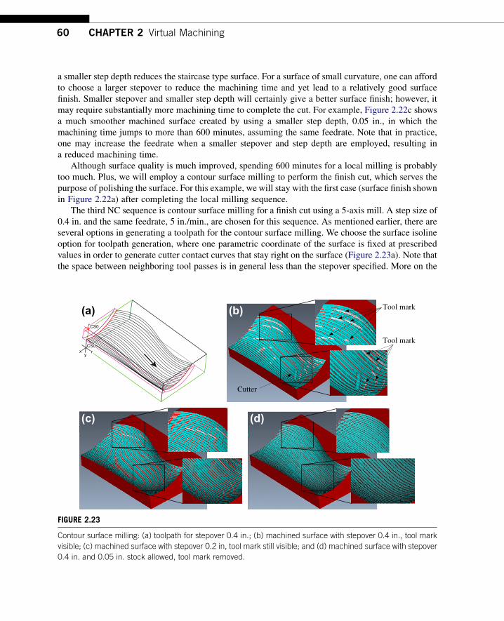
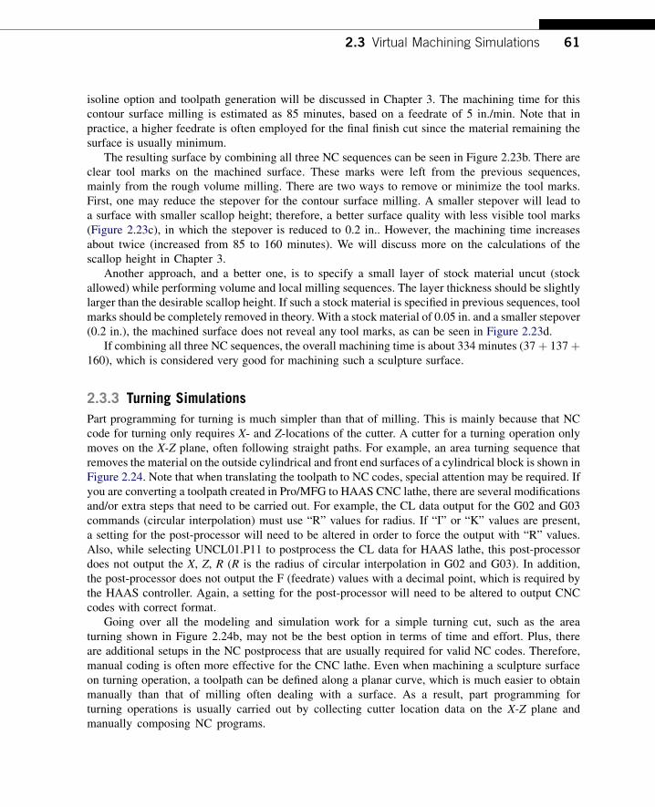
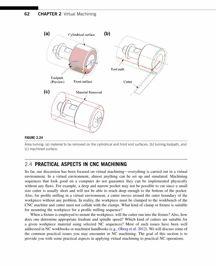
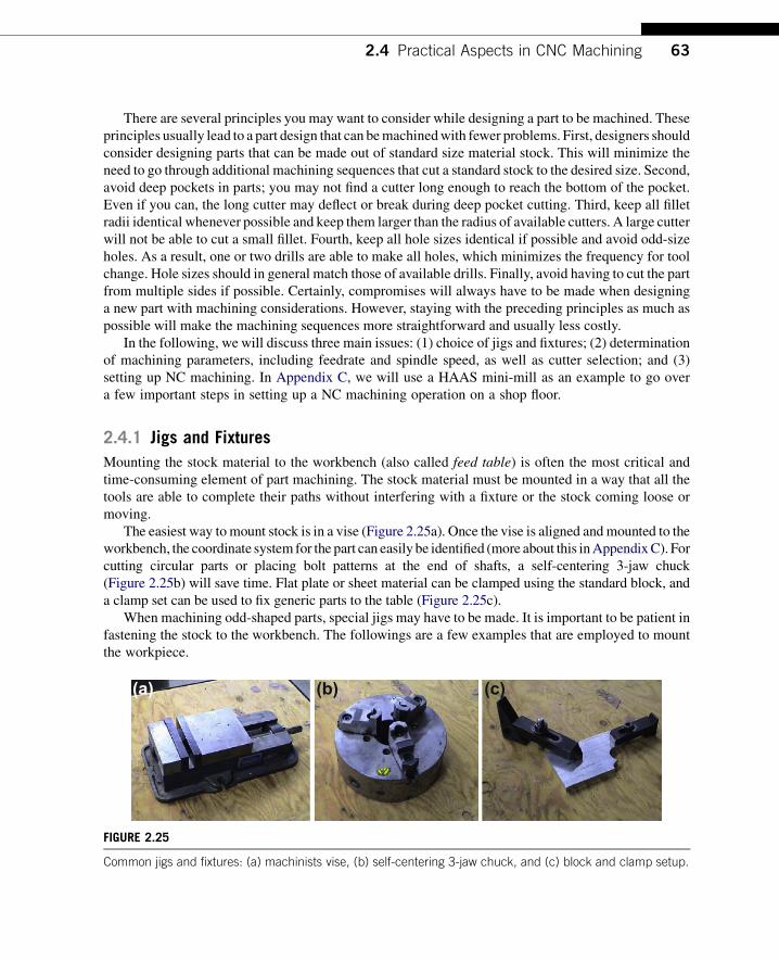
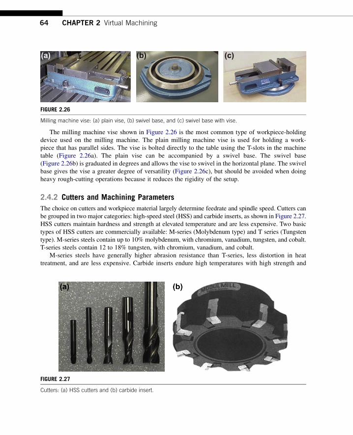
(a) (b) (c)
FIGURE 226
Milling machine vise (a) plain vise (b) swivel base and (c) swivel base with vise
64 CHAPTER 2 Virtual Machining
The milling machine vise shown in Figure 226 is the most common type of workpiece-holdingdevice used on the milling machine The plain milling machine vise is used for holding a work-piece that has parallel sides The vise is bolted directly to the table using the T-slots in the machinetable (Figure 226a) The plain vise can be accompanied by a swivel base The swivel base(Figure 226b) is graduated in degrees and allows the vise to swivel in the horizontal plane The swivelbase gives the vise a greater degree of versatility (Figure 226c) but should be avoided when doingheavy rough-cutting operations because it reduces the rigidity of the setup
242 Cutters and Machining Parameters
The choice on cutters and workpiece material largely determine feedrate and spindle speed Cutters canbe grouped in two major categories high-speed steel (HSS) and carbide inserts as shown in Figure 227HSS cutters maintain hardness and strength at elevated temperature and are less expensive Two basictypes of HSS cutters are commercially available M-series (Molybdenum type) and T series (Tungstentype) M-series steels contain up to 10 molybdenum with chromium vanadium tungsten and cobaltT-series steels contain 12 to 18 tungsten with chromium vanadium and cobalt
M-series steels have generally higher abrasion resistance than T-series less distortion in heattreatment and are less expensive Carbide inserts endure high temperatures with high strength and
FIGURE 227
Cutters (a) HSS cutters and (b) carbide insert
Flat endmilld=cutter diameter
Axis of revolution
d
(a) (b)
Ball Nose CutterIf ball is not ldquoburiedrdquo in workpiece then a will be less than cutter diameter ie no cutting occurs at full tool diameter
Cutter Axis
a
Cutting edge
FIGURE 228
Cutters (a) flat endmill and (b) ball nose cutter
24 Practical Aspects in CNC Machining 65
hardness especially suitable for high-speed cutting The tungsten carbide (WC) cuts nonferrousabrasive materials and cast irons Titanium carbide (TiC) has higher wear resistance thanWC but is notas tough Titanium carbide cuts hard materials mainly steels and cast irons
From their geometric shape there are flat endmill (Figure 228a) ball nose cutter (Figure 228b)and bull mill (Figure 220a) In general endmills are suitable for face profile and pocket milling Aball nose cutter is more suitable for sculptural surface milling since there is less tendency to gougeusing a ball nose cutter
Two of the most critical machining parameters are spindle speed and feedrate Spindle speed N(rpm) is usually determined by the cutting speed V (inmin) that is
N frac14 V=ethpdTHORN (21)
where d is the cutter diameter (in) In general factors affecting the calculation of cutting speed include(1) the material being machined (steel brass tool steel plastic wood) (2) the material the cutter ismade from (carbon steel high-speed steel carbide ceramics) and (3) the economical life of the cutterthat is the cost to regrind or purchase new compared to the quantity of parts produced
You may find recommended cutting speeds in machining textbooks or handbooks for examplessee Tables 21a and 21b As shown in the tables cutting speed is provided in a large range This isbecause there are other factors to consider while determining cutting speed (eg type of the millingsequences) A rough cut usually requires a larger cutting speed thus a higher spindle speed in order toremove material fast Different data sources may offer cutting speeds that differ by sometimessignificant amounts Numbers obtained from machining handbooks are a good starting point You mayhave to make needed adjustments onsite
Once an adequate spindle speed is determined a feedrate f (inmin) can be calculated using thefollowing equation
f frac14 ft N n (22)
where n is the number of teeth on the cutter and ft is the feed per tooth (in) as depicted in Figure 229Factors that affect the feedrate include (1) type of tool (eg a small drill vs a large end mill) (2)surface finish desired (3) power available at the spindle (to prevent stalling of the cutter or workpiece)
Table 21 Recommended Cutting Speeds
(a) Recommended by Kalpakjian and Schmid (2010)
Workpiece Material
Cutting Speed (ms)
HSS Carbide Inserts
Aluminum Alloys 15 w 6 10 thornMagnesium Alloys 3 w 5 12 thornCopper Alloys 03 w 15 15 w 7
Steels 01 w 07 05 w 4
Stainless Steels 02 w 1 1 w 2
High-Temp Alloys 005 w 01 02 w 03
Titanium Alloys 01 w 1 05 w 2
Cast Irons 02 w 06 05 w 2
(b) Recommended by Krar et al (2010)
Workpiece Material
Cutting Speed (mmin)
HSS Carbide Inserts
Machine Steel 21 w 30 45 w 75
Tool Steel 18 w 20 40 w 60
Cast Iron 15 w 25 40 w 60
Bronze 20 w 35 60 w 120
Aluminum 150 w 300 300 w 600
ftV
Rack angle
Relief angle
FIGURE 229
Feed per tooth
66 CHAPTER 2 Virtual Machining
(4) rigidity of the machine and tooling setup (ability to withstand vibration or chatter) (5) strength ofthe workpiece (high feedrates will collapse thin-wall tubing) and (6) characteristics of the materialbeing cut (eg chip flow depends on material type and feedrate)
The recommended feed per tooth for high-speed steel and carbide inserts are listed in Table 22aand 22b respectively As shown higher feed per tooth is recommended for carbide insert cutters whilecutting hard materials such as steels Also higher feed per tooth is recommended for face milling thanend milling This is because more teeth are in contact with the workpiece in face milling thus a higher
Table 22 Recommended Feed per Tooth by Krar et al (2010)
(a) High-speed steel
Workpiece Material
Face Mills End Mills
in mm in mm
Aluminum 0002 055 0011 028
Brass and bronze 0014 035 0007 018
Cast Iron 0013 033 0007 018
Bronze 0012 030 0006 015
Tool steel 0010 025 0005 013
Stainless steel 0006 015 0003 008
(b) Carbide inserts
Workpiece Material
Face Mills End Mills
in mm in mm
Aluminum 0020 050 0010 025
Brass and bronze 0012 030 0006 015
Cast Iron 0016 040 0008 020
Bronze 0012 040 0008 020
Tool steel 0014 035 0007 018
Stainless steel 0010 025 0005 013
24 Practical Aspects in CNC Machining 67
feedrate While carrying out finish cut the feedrate can be turned up if material remaining is minimalAgain numbers obtained from machining handbooks only provide a good starting point
243 Setting a CNC Sequence
In this subsection wewill go over a few important points in setting up an NCmachining sequence at theshop floor These are the things that one must be aware of when anNC program is generated and is readyto carry out the machining sequence using a CNC machine Since there are wide varieties of machineswewill only discuss two key stepswithout referring to specificmachines The goal here is to provide youwith some ideas when bringing the part program to a CNCmill and to serve as a reminder that there arepractical issues to go over before a successful machining sequence can be carried out on the shop floorWe use aHAASmini-mill as an example to illustratemore detailed procedures and setups inAppendixCfor those who are interested in learning more or those who have access to a HAAS mill
After a workpiece is loaded and secured on the workbench two key steps are followed loading andsetting up tools and setting up work coordinate and machine zero
Loading cutters is one of the most important steps in setting a CNC machining sequence You maycollect all the needed cutters and follow the machine instructions to load them to the mill Once alltools are loaded into the tool changer the lengths of each must be measured You will also need tomeasure cutter diameters if tool radius compensations are included in your NC codes Before
FIGURE 230
Using edge finder to set up X-axis
68 CHAPTER 2 Virtual Machining
measuring lengths we first place a work coordinate (or machine zero) on the stock material in the sameplace that you have set it in CAM software (such as ProMFG or Mastercam) Machine zero is usuallyplaced at the front left corner of the top surface of the stock Usually we load a drill chuck with an edgefinding tool (Figure 230) into the spindle move the edge finder to the X position of the part using thejog handle and zero the X-axis We repeat the similar steps for setting up Y-axis
The Z-axis will be set after all the tools needed for machining are loaded Often the first cutter isadvanced into the spindle Then we position the tool tip over the top of the X and Y-zero We lower thetool and place a feeler gage (Figure 231) to set zero for Z-axis Since the Z axis is zeroed using the first
FIGURE 231
Z-axis offset and tool length offset
25 Commercial Machining Simulation Software 69
tool the length offset for tool one should be zero The thickness of the feeler gage must now besubtracted from the Z axis height The same steps will have to be repeated to measure or offset the toollengths for all cutters loaded
Once these two steps are completed you are ready to load the program to the machine Usuallya CNC mill is networked with a PC In that case an NC program can be loaded to the mill very easilyOnce a program is loaded it usually automatically becomes the selected program the mill will run It isa good practice to verify the toolpath on the monitor screen of the mill like that shown in Figure 29bbefore running the program
25 COMMERCIAL MACHINING SIMULATION SOFTWAREA large number of commercial CAM software tools can currently be obtained There is general-purpose CAM software that supports turning and milling sequences There are also special-purposecodes that focus on narrow tasks (eg software for creating a toolpath only for engraving)
General-purpose software offers adequate geometric modeling capabilities Most of them aretightly integrated with an existing CAD system Roughly the general-purpose CAM software can becategorized into three main groups in terms of how they relate to a CAD system The first groupincludes CAM as one of the modules in a CAD system such as ProMFG of ProENGINEER CAMmodule of CATIA CADCAMCAE system and CAM module of the NX Unigraphics The secondgroup refers to CAM as third-party software that is seamlessly integrated into commercial CADsoftware This includes CAMWorks (wwwcamworkscom) integrated with SolidWorks Inventor-CAM (wwwinventorcamcom) with Autodesk Inventor and so on The third group includes stand-alone CAM software that is not associated with any CAD systems (eg Mastercam SurfCAM (wwwsurfwarecom) and GibbsCAM (wwwgibbscamcom))
Special-purpose codes as mentioned earlier focus on narrow tasks Some of these codes includeArtCAM (wwwartcamcom) that supports sign makers woodworkers engravers and jewelers todesign and manufacture 3D or 2D products from their artwork
This section presents a brief overview on the commercially available CAM software We willinclude a short description for one or two of the software from each group The strength weaknesspros and cons of these codes will be briefly discussed
251 General-Purpose Machining Software
Major CAD systems such as ProENGINEER CATIA and NX are equipped with a CAM modulethat is part of the CAD and is seamlessly integrated with the respective CAD systems As mentionedbefore other major CAD systems (eg SolidWorks or AutoDesk) offer a CAM module that isdeveloped by a third party and is seamlessly integrated with the CAD systems as well All such CAMmodules provide excellent virtual machining capabilities in support of a broad range of machiningsequences including profile milling volume milling surface milling hole-making text-engravingand so on These capabilities support users to create virtual machining simulation generate a toolpathand convert the toolpath into CNC codes following the steps depicted in Figure 212a Development ofsoftware in this category essentially started with CAD and then extended to include CAM eitherthrough its own development and acquisition or via a third party
70 CHAPTER 2 Virtual Machining
The major advantage of these software tools is that they require a relatively short learning curve fornew CAM users This is mainly because the user is already familiar with the basic operations andprocedures of using the CAD portion of the software Learning CAM that is a built-in module ofa CAD system the user is familiar with is relatively straightforward However using CAD-centeredCAM module users must start with creating 3D solid models that represent design and workpieceeven for a simple cut such as hole drilling
One thing worth noting is that CAMWorks offers a knowledge base and Automatic FeatureRecognition (AFR) tools to help users in the machining processes The AFR technology analyzes solidmodel geometry and identifies machineable features (eg holes slots pockets and bosses) Theknowledge base is a self-populating database that contains information about the cutting tools andthe parameters used by the operator as well as information regarding the cutting tools available on theshop floor This database helps store the best practices at a centralized location in the tool room
On the other hand software such as Mastercam SurfCAM and GibbsCAM (all general-purposeCAM software) were developed and marketed with the sole purpose of supporting virtual machiningwhich is essentially CAM-centered These tools offer excellent capabilities for virtual machiningoften even more general and versatile than those integrated in CAD systems For example Mastercamprovides more options for generating a toolpath for contour surface milling including the constantscallop height option that was not available in ProMFG
In general virtual machining can be carried out with these tools using wireframe surface orsolid geometric entities For example a pocket milling or a profile milling only requires a simplewireframe sketch that describes the geometry of the pocket and profile boundary of the part This ismuch simpler and requires less effort compared with that of using a CAD-centered CAM moduleHowever none of the geometric entities created in such tools are parametric which are not suitablefor design changes They are created using points lines and patches as well as basic extrusionsweep and rotate operations Modeling capabilities in CAM-centered software are in general inferiorto those in CAD
252 Special-Purpose Machining Software
Special-purpose software offers toolpath generation for narrow tasks Some of these codes includeArtCAM and DeskCNC among many others These software tools are very much tailored for specificmachining tasks in narrow applications
ArtCAM supports sign makers woodworkers engravers and jewelers who design and manufac-ture 3D or 2D products from their artwork Users can create highly intricate personalized or custom 3Dmodels from 2D sketches or photographs The software guides users through the entire process fromconceptual sketch to the finished piece or mold An example of The Black Bull sign-making inArtCAM is shown in Figure 232a for reference
DeskCNC is another popular code for engraving The tool supports users to bring in drawingsphotographs or any other computer graphic image and convert it into a DXF file or into G-Code readyto be machined Screen captures in Figure 232b show the process of converting an image into theactual toolpath used in creating the finished engraving The original file is loaded into DeskCNC andconverted andor processed into a grayscale image by numerous available graphics filters Once theimage is processed DeskCNC converts the picture files directly into toolpaths for an engravingmachine
FIGURE 232
Examples of special-purpose software (a) ldquoThe Black Bullrdquo sign making in ArtCAM (wwwartcamcomvideos
2011-online-demo-catchuphtml) and (b) the process of converting an image into the actual toolpaths using
DeskCNC (wwwdeskamcomdeskarthtml)
25 Commercial Machining Simulation Software 71
Another special-purpose code worth-mentioning is CNCezPRO It is a real-time 3D simulator forCNC toolpath verification equipped with good real-time rendering and 3D visualization of tool cutsUsers are able to write edit and revise G- and M-codes and visualize the toolpath in real time Forexample a trajectory milling (or slot milling) on XZ (G18) and YZ (G19) planes can be generated andsimulated in CNCezPRO as shown in Figure 233a In addition a user-defined post-processor forcustomized G- and M-codes and a macro language for custom cycles make CNCezPRO a powerfultool-proving package for any shop Other similar software includes CNC Simulator (see Figure 233b)CutViewer (wwwcutviewercom) AutoEditNC (wwwbetatechnicalcomautonchtm) and CIMCOEdit (wwwcimcocom)
FIGURE 233
Examples of special-purpose software for manual CNC programming and toolpath verification (a) a trajectory
milling in CNCezPRO (wwwcncezprocom) and (b) pocket and profile milling using CNC Simulator (www
cncsimulatorcom)
72 CHAPTER 2 Virtual Machining
26 CASE STUDY AND TUTORIAL EXAMPLESIn this section we will present a case study where virtual machining is conducted for machining diesthat cast tracked vehicle roadarms In addition to virtual machining this case involves mold designusing ProMOLD a software module of ProENGINEER that supports mold design in a computer Thepurpose of presenting this case study is to demonstrate that virtual machining is applicable to practicalengineering applications in industry In addition tutorial examples including a name plate andsculpture surface machining will be discussed Step-by-step instructions for creating these tutorialexamples are given in tutorial M4 S4 and P4 at the end of this book
261 Case Study
Virtual manufacturing is applied to develop and simulate the manufacturing process for tooling thatcast tracked vehicle roadarms The die-casting process is assumed for fabricating green parts of theroadarm which involves design and machining of the cover and ejector dies The machined dies canthen be used to die cast the green parts of the roadarm Most die castings are made from non-ferrousmetals specifically zinc copper aluminum magnesium lead pewter and tin based alloys We assumethat the roadarms are made from aluminum which is light weight with high strength The schematicillustration of the manufacturing process is given in Figure 234 As shown in the figure die castingproduces two parts per operation in this design Volume milling and drilling are used to machine thegreen part for the final roadarms by removing extra material that remains in the spruce and runners aswell as drilling holes at each end
Two dies cover and ejector are designed using ProMOLD A sprue which is a countersink hole iscreated on the top face of the cover die as shown in Figure 235a Circular shape runners are createdbetween the cover and ejector dies In addition waterlines are created in both dies for coolingpurposes as shown in Figure 235a
The machining operations of the dies involve volume milling that removes most of the cavitymaterial (plus sprue and runners) local milling that cleans up material left from the volume milling
Cover die
Ejector die Green part
Machined parts
Remaining material
Cover die
Ejector die
Sprue
Waterlines
Runner
(a) (b) (c)
FIGURE 234
Schematic illustration of roadarm manufacturing process (a) mold design (b) explode view and (c) machined
parts
Waterlines
Runners Cavity
Spruce Waterlines
Runners Cavity Top
Face
(a) (b)
FIGURE 235
Design of cover and ejector dies (a) cover die and (b) ejector die
Table 23 Cutters Used for Volume Milling
NC 1 NC 2
Length 3 in 3 in
Diameter 1 in 025 in
Round 01 in 01 in
Table 24 Manufacturing Parameters for Volume Milling
NC 1 NC 2
Cut Feed 10 inmin 10 inmin
Step Depth 05 in 01 in
Stepover 07 in 02 in
Spindle speed 2000 rpm 2000 rpm
Machining Time 92 minutes 587 minutes
26 Case Study and Tutorial Examples 73
contour surface milling that further cleans up the cavity surface grinding that polishes the cavitysurface by removing the leftover scallops and hole drilling for the waterlines Hot work H13 die steelis selected as the material for the die workpiece For illustration purposes only volume milling andcontour surface milling performed on the cover die are shown To begin the machining operation forthe cover die a workpiece of 8 in 525 in 2 in rectangular block is first created
A 3-axis mill is assumed for performing two NC sequences of volume milling The first sequenceremoves the top thin layer of the workpiece to generate a smooth surface The thin layer thickness is0125 in The second volume milling cuts the cavity and runners Cutters and machining parameters ofthe NC sequences are listed in Tables 23 and 24 respectively As shown in Table 24 the machiningtimes of the two NC sequences are 92 and 587 minutes respectively
FIGURE 236
NC sequence 1 of volume milling (a) milling simulation and (b) toolpath
FIGURE 237
NC sequence 2 of volume milling (a) milling simulation and (b) toolpath
74 CHAPTER 2 Virtual Machining
Simulation of these two NC sequences in ProMFG is illustrated in Figures 236 and 237respectively The first sequence creates a smooth flat surface The second sequence cuts the cavity butgenerates stair case type surface which is not smooth Note that the distance between the stair layers iscontrolled by the step depth manufacturing parameter which is 01 in in this case The cavity surfacemust be machined again using contour surface milling for a smoother surface This will minimize thegrinding operation
A 3-axis mill is assumed for performing the contour surface milling Note that five-axis millusually produces better surface smoothness for contour surface milling The cutter of length 2 indiameter 025 in and round radius 0125 in is used for the contour milling The machining parametersare summarized in Table 25
Table 25 Manufacturing Parameters for Contour Surface Milling
Contour Surface Milling
Cut Feed 10 inmin
Stepover 025 in
Spindle Speed 2000 rpm
Machining Time 359 minutes
FIGURE 238
NC sequence of contour surface milling (a) milling simulation and (b) toolpath
26 Case Study and Tutorial Examples 75
The contour surface milling simulation is performed as shown in Figure 238a The toolpath of themachining operation is shown in Figure 238b The total machining time is estimated as 359 minutesNote that the cavity surface is still not smooth The scallop remaining on the cavity surface can bereduced by using a smaller stepover and manufacturing time will increase Grinding operations areoften employed to polish the cavity surface which is not simulated
Virtual Machining for Green PartWith the dies fabricated the die-casting process can be carried out Assuming the casting process hasbeen performed the roadarm green part shown in Figure 234b is obtained The volume milling isperformedfirst to remove the extramaterial remaining in the runners and sprue then to create holes in theroadarm Using the roadarm green part as the workpiece the 3-axis milling machine is again selected
The volume milling simulation for the center hole is presented as shown in Figure 239a Themachining time for thevolumemilling is found to be29minutes and the toolpath is shown inFigure239b
Using the preceding virtual manufacturing process the manufacturability of the optimal roadarmcan be verified In addition to the simulation and machining time estimate ProMFG generates cutter
FIGURE 239
Volume milling operation for the middle hole (a) milling simulation and (b) toolpath
76 CHAPTER 2 Virtual Machining
location data that can be converted into G-code and M-code for CNC using a proper post-processorCertainly special fixtures must be design and fabricated to support the machining sequences of thegreen part and cutting the hole of the roadarm
262 Tutorial Examples
A name plate and a sculpture surface example are included in the tutorial lessons This name plateexample involves profile and volume millings and is presented so that you may learn to use ProMFG
EXAMPLE 21 NAME PLATEThis tutorial example involves designing and creating a toolpath for machining a customized name plate ona 3 in 12 in ⅜ in workpiece using both ProMFG and Mastercam
Two NC sequences volume milling and engraving are created using ProMFG Nine letters ldquoName Platerdquoaresketched on the top surface of the rectangular block and extruded 18 in into the block as a cut feature as shown inFigure 240a Note that a CG Triumvirate Inserat font is chosen for the alphabets You may draw a spline curve andchoose ldquoPlace Along Curverdquo to place the text along the curve (see Figure 240b)
A 18 in end mill is picked to make the cut As shown in the machining simulation this small cutter is able toreach most pocket areas to make cuts except the narrow area (eg the narrow cross line in the letter N) and sharpcorner In general the toolpath generated for volume milling is acceptable
Note that in creating a volume milling sequence using ProMFG users will have to create a ldquomill volumerdquo whichdefines the portion of the workpiece to be removed In using ProMFG creating a mill volume involves makinga sketch extruding the sketch for a solid block and intersecting the block with the design model to generate a trimsolid feature that represets exactly the material to be removed For some intricate surfaces ProMFGmay not be ableto process the trim function
The toolpath for the engraving sequence in this example is created using a Groove feature in ProENGINEER Asshown in Figure 240d six lettersdldquoGrooverdquodin an outline style are defined in the design model The same cutterwith a step depth 18 in is chosen for the engraving NC sequence Note that the text engraved will have the samesize as the cutter (18 in) that is the cutter will move one pass along the outer profile of individual letters
A similar name plate design is created for Mastercam as shown in Figure 241a The MC9 font is chosen tocreate the ldquoMASTERCAMrdquo text Note that a simple 2D wireframe sketch is sufficient for this machining simulationthere is no need to create 3D solid models Two sequences are created a profile milling that cuts along the outerboundary of the workpiece and a volume milling that cuts the area between the inner boundary curve and the outerprofile of individual letters A 18 in end mill with a step depth of 18 in is picked to make the cut The toolpath(profile milling and volume milling combined) and machining simulation are shown in Figures 241b and 241crespectively
FIGURE 240
CNC sequences for machining a name plate using ProMFG (a) creating text for volume milling (b) adding
a spline (c) machining simulation in Vericut and (d) adding text for an engraving sequence
10
10
05 02
(a)
(b) (c)
FIGURE 241
Volume CNC sequences for machining a name plate using Mastercam (a) creating text for volume milling
(b) combined toolpath and (c) machining simulation
26 Case Study and Tutorial Examples 77
andor Mastercam in projects P4 and M4 respectively In addition after going through this simpleexample you should see the major differences between the two software tools and hopefully be able toidentify a few pros and cons of each Once you are more familiar with one of these two software toolsyou may move to the second tutorial exampledblock with a sculpture surfacedin which both rough
78 CHAPTER 2 Virtual Machining
and finish cuts are required Three CAM software ProMFG Mastercam and CAMWorks areemployed for this example Since some information about this example has been discussed in Section23 using ProMFG we will focus more on Mastercam Machining the block using CAMWorks isdiscussed in Tutorial S445 This example should help you become more familiar with ProMFGMastercam andor CAMWorks
EXAMPLE 22 BLOCK WITH A SCULPTURE SURFACENC sequences for machining the sculpture surface of the block example discussed in Section 23 is chosen as thesecond tutorial example As discussed in Section 23 three NC sequencesdvolume milling local milling andcontour surface millingdwere employed for machining the surface using ProMFG This example focuses on usingMastercam to create a similar machining simulation
We will create three sequences using Mastercamdsurface rough flowline rough-restmill and surface finishdwhich correspond to volume milling local milling and contour surface milling in ProMFG Since creating thesculpture surface by blending circular arcs on four parallel planes using Mastercam is more time consuming we willimport the ProENGINEER part of the block into Mastercam Mastercam supports model import directly from ProENGINEER in addition to other CAD systems (eg SolidWorks CATIA and AutoDesk)
The ProENGINEER part will be imported into Mastercam in a default position and orientation similar to that ofFigure 242a The imported geometric entities usually must be rotated and translated to a proper position andorientation (similar to those shown in Figures 242b and 242c) so that the machine zero coincides and aligns withthe coordinate system built in Mastercam
A surface rough flowline with a 1 in bull mill of frac14 in corner radius was chosen for the rough cutFlowline is one of the several options available in Mastercam Flowline cuts single or multiple surfacesusing their natural shape to define the toolpath Stepover and step depth are 04 in and 02 inrespectively These parameters are identical to those defined in ProMFG A flowline direction along
FIGURE 242
Adjusting position and orientation for the imported part (a) default position and orientation (b) rotate 90 alongX-axis and (c) rotate 90 along Z-axis and then translate 4 units along the Z-axis
(a) (b)
(c)
FIGURE 243
Surface rough flowline machining in Mastercam (a) flowline direction (b) toolpath and (c) machining
simulation
26 Case Study and Tutorial Examples 79
the short edge of the surface (Figure 243a) is chosen The resulting toolpath and machining simulationare shown in Figure 243b and 243c respectively
As can be seen in Figure 243b Rough Flowline does a similar cut to that of volume milling inProMFG Mastercam does not require defining mill volume as that of ProMFG and requires fewersteps to generate a similar toolpath
The next sequence is Rough-Restmill which removes remaining materials from the previousrough cut Rough-Restmill is very similar to local milling in ProMFG The same frac12 in ball-nose cutter and the same stepover and maximum step depth are chosen to perform thissequence The resulting toolpath and machining simulation are shown in Figure 244a and244b respectively Note that the restmill toolpath follows a spiral pattern similar to that of ProMFG
The third and final sequence is finish cut A finish-scallop and the same frac12 in ball-nosecutter are chosen The finish-scallop option generates finishing toolpaths that have consistentscallop heights over the entire set of surfaces which is a desired option to perform a finish cutA maximum stepover 005 in is specified for this sequence Note that a similar option is notavailable in ProMFG The resulting toolpath and machining simulation are shown inFigure 245a and 245b respectively As shown in Figure 245b the surface looks fairly smooth
(a) (b)
FIGURE 244
Surface rough restmill machining in Mastercam (a) toolpath and (b) machining simulation
(a) (b)
FIGURE 245
Surface finish-scallop machining in Mastercam (a) toolpath and (b) machining simulation
80 CHAPTER 2 Virtual Machining
This is because a very small maximum stepover (005 in) is specified for the finish cut Asa result the overall machining time estimated is 7 hours and 18 minutes as reported byMastercam
27 SUMMARYIn this chapter we discussed the subject of virtual machining including NC part programming virtualmachining simulations simulation software that is commercially available as well as a case study andtutorial examples In addition we briefly addressed the practical aspects in CNC machining includingjigs and fixtures cutters and machining parameters and steps in operating HAAS mini-mill We hopethis chapter has helped you become more familiar with the subject With more practice you shouldbecome more confident and competent in using virtual machining simulation tools to address the
Questions and exercises 81
manufacturability of the product and obtain reasonable machining time estimates and required setup tosupport product design
In the next chapter we will introduce the topic of toolpath generation which is the backbone ofvirtual machining simulation It should provide you with a more in-depth understanding on the factorsthat contribute to the CNC toolpath generated in virtual machining simulation For those who areconducting research relevant to virtual machining or toolpath generation Chapter 3 should serve wellas an introductory article for understanding toolpath generation For practicing engineers the chapteroffers behind-the-scene operations in the calculation of cutter location data and parameters that affectthat data Knowledge acquired will help you diagnose problems encountered on the machined surfaces(eg gaging)
In the remaining chapters of this book we will describe other pertinent technology that supportsaddressing the manufacturing issues from design perspectives including sheet forming simulation(Chapter 4) rapid prototyping (Chapter 5) and manufacturing cost estimates (Chapter 6) CNCmachining discussed in this chapter and rapid prototyping in Chapter 5 offer a means to support fastprototyping in product development These chapters should provide you with a very good under-standing on the essential topics involved in product manufacturing using advanced computer-aidedtechnology
QUESTIONS AND EXERCISES
21 Write a CNC program (with explanations for each block) for a HAAS mill to machine a 4 in
425 in 25 in aluminum block for the part (design model) shown in the following image andtable Choose your own cutters (from those shown in the table) and cutting parameters (step depthand stepover) with ldquocommon senserdquo Note that you need to use tool radius compensation for alltoolpaths Calculate the overall cutting time
Size (inches) Type Length (inches)18 Ball-nose 0375 316 Ball-nose 1000 14 Ball-nose 0625 12 Ball-nose 2000 18 Flat-end 0375 316 Flat-end 0475 14 Flat-end 0500 14 Flat-end 0875 516 Flat-end 0600 38 Flat-end 0600 12 Flat-end 1000 12 Flat-end 1500
22 Verify your NC program of 21 using an adequate software tool Search and find a softwareprogram that takes your NC program and simulates the NC sequence
82 CHAPTER 2 Virtual Machining
23 Write a NC program to cut a 025 in-deep pocket on a 3 in 3 in 05 in block shown in thefollowing figure The cutter diameter is 05 in Note that the cutter will cut inside of the pocket bymoving along the pocket boundary only one time which will leave some material uncut Youmust use tool radius compensation for the NC codes Identify the uncut area Also sketch yourtoolpath which must start from point A
Point A
B
24 Write a complete APT (Automatically Programmed Tools) program to cut a 025 in-deep pocketon a 3 in 3 in 05 in block shown in the following figure The cutter diameter is 075 in Notethat spindle speed is 580 and feedrate is 23 Note that the cutter must start from point SP andreturn to SP after the cut
P1
SP
P4 P3
P2
L3
L1
L2 L4
25 Use ProMFG CAMWorks or Mastercam (or other CAM software you have access) to machinethe design model shown below (left) from a workpiece of 12 in8 in45 in (show below right)Note that at least two NC sequences are needed face milling that removes top layer of 05 in deepfrom top surface of the workpiece then pocket milling that cuts the pocket
Questions and exercises 83
26 Design and machine a nameplate on a 3 in12 in ⅜ in Plexiglas workpiece using theHAAS CNC mill (or other mill you have access) Note that you can design your plateusing ProMFG (CAMWorks or Mastercam) directly write your CNC codes using HAAScommands or any other software tools that you found This will be a combination of textengraving volume and trajectory milling and picturelogo carving The following is whatyou need to submit for grade Please BE VERY CREATIVE(a) Your design describe it briefly in a few sentences and use pictures for illustration(b) Your CNC codes with explanations (only important blocks no need to submit the entire NC
program)(c) Final machined nameplate (if applicable)(d) Two significant things that you learned from using the mill
ReferencesChang T-C Wysk RA Wang H-P 1998 Computer-Aided Manufacturing second ed Prentice HallKalpakjian S Schmid SR 2010 Manufacturing Engineering and Technology sixth ed Prentice HallKrar S Gill A Smid P 2010 Technology of Machine Tools seventh ed McGraw-HillOberg E Jones F Horton H Ryffel H McCauley C 2012 Machineryrsquos Handbook twentyninth ed
Industrial PressSarma R Dutta D 1997 An integrated system for NC machining of multi-patch surfaces Computer-Aided
Design 29 (11) 741ndash749Smid P 2000 CNC Programming Handbook second ed Industrial Press Inc 200 Madison Avenue New York
NY 10016-4078
84 CHAPTER 2 Virtual Machining
APPENDIX A SAMPLE ADDRESS CODES
A Fourth-axis rotary motion The A address character is used to specify motion forthe optional fourth A axis It specifies an angle indegrees for the rotary axis It is always followed bya signed number and up to three fractional decimalpositions
B Fifth-axis rotary motion The B address character is used to specify motion forthe optional fifth B axis It specifies an angle indegrees or the rotary axis It is always followed bya signed number and up to three fractional decimalpositions
C Auxiliary external rotary axis The C address character is used to specify motion forthe optional external sixth C axis It specifies an anglein degrees for the rotary axis It is always followed bya signed number and up to three fractional decimalpositions
D Tool diameter selection The D address character is used to select the tooldiameter or radius used for cutter compensation
F Feedrate The F address character is used to select the feedrateapplied to any interpolation functions including pocketmilling and canned cycles
G Preparatory functions (G-codes) The G address character is used to specify the type ofoperation to occur in a block
H Tool length offset selection The H address character is used to select the tool lengthoffset entry from the offsetrsquos memory
I J K Canned cycle and circular optionaldata
The I J and K address character is used to specify dataused for some canned cycles and circular motions
L Loop count for repeated cycles The L address character is used to specify a repetitioncount for some canned cycles and auxiliary functions
M Code miscellaneous functions The M address character is used to specify an M-codefor a block These codes are used to controlmiscellaneous machine functions
N Number of block The N address character is entirely optional It can beused to identify or number each block of a program
R Canned cycle and circular optionaldata
The R address character is used in canned cycles andcircular interpolation
S Spindle speed command The S address character is used to specify the spindlespeed
T Tool selection code The T address character is used to select the tool for thenext tool change
X Y Z Linear X- Y- and Z-axis motions The X- Y- and Z-address characters are usedto specify motion for the X-axis It specifiesa position or distance along the X- Y- and Z-axesrespectively
Appendix B Sample G- and M-Codes 85
APPENDIX B SAMPLE G- AND M-CODES
G-Code Function
G00 Rapid Motion
G01 Linear Interpolation Motion
G02 CW Interpolation Motion
G03 CCW Interpolation Motion
G04 Dwell
G12 CW Circular Pocket Milling
G13 CCW Circular Pocket Milling
G17 XY Plane Selection
G18 ZX Plane Selection
G19 YZ Plane Selection
G20 Select Inches
G21 Select Metric
G28 Return to Reference Point
G29 Return From Reference Point
G40 Cutter Comp Cancel
G41 2D Cutter Compensation Left
G42 2D Cutter Compensation Right
G43 Tool Length Compensation thornG44 Tool Length Compensation G47 Text Engraving
G49 G43G44G143 Cancel
G80 Canned Cycle Cancel
G81 Drill Canned Cycle
G82 Spot Drill Canned Cycle
G83 Normal Peck Drill Canned Cycle
G84 Tapping Canned Cycle
G85 Boring Canned Cycle
G86 BoreStop Canned Cycle
G87 BoreStopManual Retract Canned Cycle
G88 BoreDwellManual Retract Canned Cycle
G89 BoreDwell Canned Cycle
G90 Absolute
G91 Incremental
G98 Initial Point Return
G99 R Plane Return
M-Code Function
M00 Stop Program
M01 Optional Program Stop
M02 Program End
M03 Spindle Forward
M04 Spindle Reverse
M05 Spindle Stop
M06 Tool Change
M08 Coolant On
M09 Coolant Off
M30 Prog End and Rewind
M97 Local Sub-Program Call
M98 Sub Program Call
M99 Sub Program Return or Loop
86 CHAPTER 2 Virtual Machining
APPENDIX C HAAS MINI-MILLWe use a HAAS mini-mill as an example to illustrate detailed procedures and setups for those who areinterested in learning more andor those have access to a HAAS mini-mill
Basic Machine ConfigurationThe HAAS mini-mill is a 3-axis mill with a work envelop 16 in 12 in 10 in as shown inFigure 246 The maximum spindle speed and rapid feed are 6000 rpm and 600 ipm (inmin)respectively There are 10 tool changers in the tool pocket (or tool turret) which are able to hold 10
(b)(a)
Jig table
Tool Pockets
Spindle
Coolant tube
FIGURE 246
HAAS mini-mill (a) exterior and (b) interior
Appendix C HAAS Mini-Mill 87
different cutters The mini-mill is relatively less expensive and is affordable for academia and a smallshop All stock material that will be machined must be rigidly mounted to the jig table The machinistmust be aware of oversized stock material extra jig components (eg clamps and vises) andextended-length milling tools to avoid collision with the spindle
Prestart and Power-UpBefore powering up the mill there are a few things to checkdfor example coolant liquid level airpressure and so on
Power-Up
The green button at the top left corner of the control panel (Figure 247) will turn on the mill Themachine will boot up and an alarm message will appear Not to worry this is normal it simply meansthat the mill has not gone through a calibration process yet Press the ZERO RET button on the controlpanel then the AUTO ALL AXES button to calibrate the machine Make sure the millrsquos door is closedThe table will move to the nearest left corner with the spindle retracted to the highest point Themachine is now powered up and ready for user control
The HAAS mill uses six modes of operation to complete the tasks needed for milling a part theyare circled in Figure 247 (left most column) The user must enter one of these modes in order to useany of the four action buttons to the right
Moving the Jig TableEnter the jog mode by pressing the HANDLE JOG button (Figure 247) Press the 1100 button thiswill move the table 01 inches per tick of the jog handle in the corresponding direction The user canspecify a smaller increment using the remaining action buttons
POWER ONOFF
SPINDLE LOAD
E - STOP
JOG HANDLE
FIGURE 247
HAAS mini-mill control panel with action buttons
(a) (b)
FIGURE 248
Moving the jig table (a) axis jog buttons and (b) jog handle
88 CHAPTER 2 Virtual Machining
Press the thornX or X button (Figure 248a) The buttons surrounding the JOG LOCK button are forthe user to select which axis is to be moved Rotate the jog handle (Figure 248b) in the clockwise orpositive direction to move the table right Position the table so that it will be easier to mount yourworkpiece
Tool LoadingLoading cutters is one of the most important steps in presetting a CNC machining sequence You maycollect all the needed cutters and follow the steps to load them to the mill First enter the MDI mode(Manual Data Input) (see Figure 247) Press ATC FWD or ATC REVuntil tool one is in the spindle Getthe tool to be loaded and insert it in the spindle as far as it will go Press and hold the TOOL RELEASEbutton (see Figure 249) A blast of air will shoot out of the spindle to clear any debris Push the tool upinto the spindle and release the button
FIGURE 249
Tool release and program reset
FIGURE 250
Work coordinate list
Appendix C HAAS Mini-Mill 89
Work Coordinate SetupThe work coordinate must be placed on the stock material in the same place that you have set it inProMFG or Mastercam (or other CAM software) The HAAS mini-mill has 14 different workcoordinates that can be set independently of one another (see Figure 250) The OFSET button can betoggled to view these coordinate offsets (see Figure 251) While the screen is displaying the offsets forthe coordinates use the up and down arrows in the center of the control panel to select the X-axis forthe coordinate system the user will be working in The default coordinate system is G54
Axis Part ZeroNow we are setting the machine zero (or axis part zero) using the following steps
1 Load a drill chuck with an edge-finding tool (Figure 252) into the spindle2 Enter HANDLE JOG mode (see Figure 247) Note that the display on the screen will not change3 Turn the spindle clockwise using the CW button (Figure 253)4 Move the edge finder to the X position of the part using the jog handle (Figure 254)5 Press PART ZERO SET (Figure 249) to zero the X-axis The Y-axis should now be highlighted in
the display
FIGURE 251
Display menu
FIGURE 253
Spindle and feed control
FIGURE 254
Using edge finder to setup X-axis
FIGURE 252
Feeler gage and edge finder
90 CHAPTER 2 Virtual Machining
G90 G54 G00 X0 Y0
FIGURE 255
X-Y coordinate zero check
Appendix C HAAS Mini-Mill 91
Repeat steps 3 through 5 to zero the Y-axis The Z-axis will be set after all the tools needed formilling are loaded
Z-Axis OffsetOnce all tools are loaded into the tool changer the lengths of each must be measured First the Z-axis isoffset using a feeler gage (Figure 256)
1 Advance tool 1 into the spindle by enteringMDImode and typing T1 then press theWRITE buttonin the lower right of the control panel
2 Press ATC FWD to move directly to tool 2 Be sure the part is out of the way before the tool changewhen using extended-length tools
3 Check the X- and Y-axis zero points by entering the contents of Figure 255 into MDI modeThe block G54 may be changed if the user selects a different coordinate system (eg G55 G59)
4 Close the door and press CYCLE START (Figure 248b) This will load into memorywhich coordinate system you will be using as well as move the table to the X-Y zero position
5 Position the tool over the area in which the Z offset can be measured there must be room for thefeeler gage as well (Figure 256)
6 Press OFSET and use the arrow keys to highlight the Z-axis offset under the proper coordinatesystem
7 Press PART ZERO SET (Figure 249) to zero the Z-axis
FIGURE 256
Z-axis offset and tool length offset
92 CHAPTER 2 Virtual Machining
Tool Offset MeasureThe lengths of each tool will be based on that of tool 1 Since the Z-axis is zeroed using tool 1 thelength offset for tool 1 should be zero Check this by toggling the OFSET button (Figure 251) todisplay the tool offset lengths Highlight tool 1 and press TOOL OFSET MESUR (Figure 249) thevalue should become zero
Offsetting ToolsDo the following to use the offsetting tools
1 Retract the tool using the handle jog Z-axis positive direction2 Press ATC FWD to the next tool and handle jog it down to the Z zero surface using the feeler gage3 Highlight the tool in the offset display and press TOOL OFSET MESUR (Figure 249) The value
that appears will be the difference in length of the tool in the spindle to tool 24 Repeat previous steps until all tools are measured
The thickness of the feeler gage must now be subtracted from the Z-axis height Toggle the OFSETdisplay to the work coordinate offsets Highlight the Z-axis and type in the negative of the feeler gagethickness and press WRITE
Loading a ProgramOnce a program is loaded using the following steps it automatically becomes the selected program themill will run if the cycle start button is pressed
1 Press LIST PROG (Figure 247) to start the program control mode programs are downloadeduploaded and deleted from this mode
2 Type in the program number starting with the letter ldquoOrdquo before the number3 Press WRITE4 Press RECV RS232 (Figure 247) to prepare the mill to receive a file from the connected computer5 Start the NCnetLite program on the computerrsquos desktop6 Click the green thumbs up button to connect to the mill (Figure 257)7 Click the transmit button and select the file to send The file is automatically sent after the OK
button is selected
THUMBS UP TRANSMIT
FIGURE 257
Loading NC program
Appendix C HAAS Mini-Mill 93
A program can be edited if the user enters the EDIT mode It is recommended that onlysmall changes be made in this mode due to the limited ability to verify the toolpaths after thispoint
Running a ProgramAfter doing the following steps do not increase the rapid feed until the program has verified that thefirst few cuts are correct
1 In the LIST PROG mode highlight the program to be run then press SELECT PROG (Figure 247)2 Enter the MEM mode and change the display by pressing CURNT COMDS (Figure 253)3 Reduce the rapid motion to 5 (Figure 253) and run the program by pressing CYCLE START
(Figure 248b)
If the cuts are not correct press the FEED HOLD (Figure 248b) button to stop the table feed thenpress RESET to turn off the spindle and coolant (Figure 249) Handle jog the tool out of the part andcall the shop supervisor for assistance
Once the program has completed remove the part and tools then clean the mill from any materialchips or spilled coolant
- 2 Virtual Machining
-
- 21 Introduction
- 22 NC Part Programming
-
- 221 Basics of NC Machines
- 222 Basic Concept of Part Programming
- 223 Computer-Assisted Part Programming
- 224 CADCAM Approach
-
- 23 Virtual Machining Simulations
-
- 231 Basic Machining Simulations
- 232 Advanced Machining Simulations
- 233 Turning Simulations
-
- 24 Practical Aspects in CNC Machining
-
- 241 Jigs and Fixtures
- 242 Cutters and Machining Parameters
- 243 Setting a CNC Sequence
-
- 25 Commercial Machining Simulation Software
-
- 251 General-Purpose Machining Software
- 252 Special-Purpose Machining Software
-
- 26 Case Study and Tutorial Examples
-
- 261 Case Study
- 262 Tutorial Examples
-
- 27 Summary
- Questions and Exercises
- References
- Appendix A Sample Address Codes
- Appendix B Sample G- and M-Codes
- Appendix C HAAS Mini-Mill
-
- Outline placeholder
-
- Basic Machine Configuration
- Prestart and Power-Up
-
- Power-Up
-
- Moving the Jig Table
- Tool Loading
- Work Coordinate Setup
- Axis Part Zero
- Z-Axis Offset
- Tool Offset Measure
- Offsetting Tools
- Loading a Program
- Running a Program
-
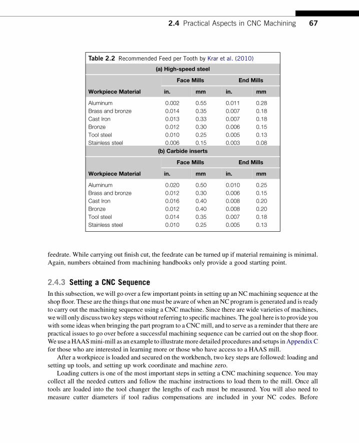
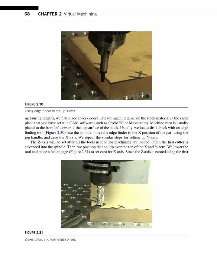
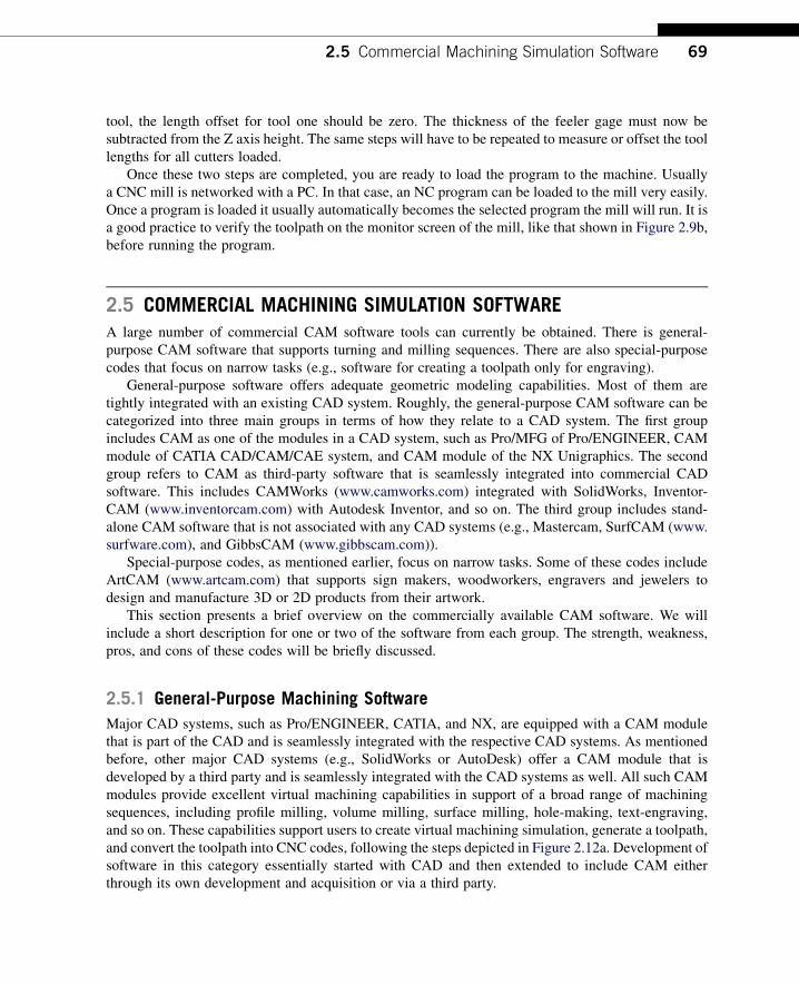
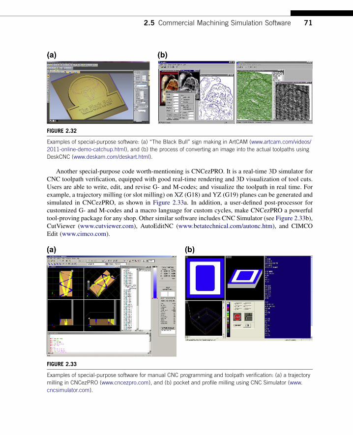
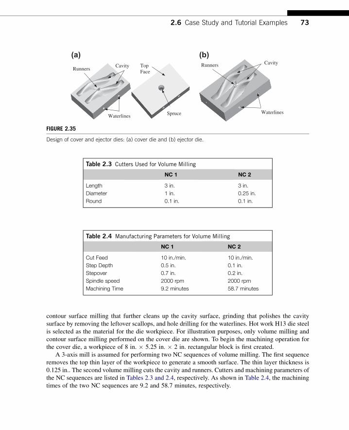
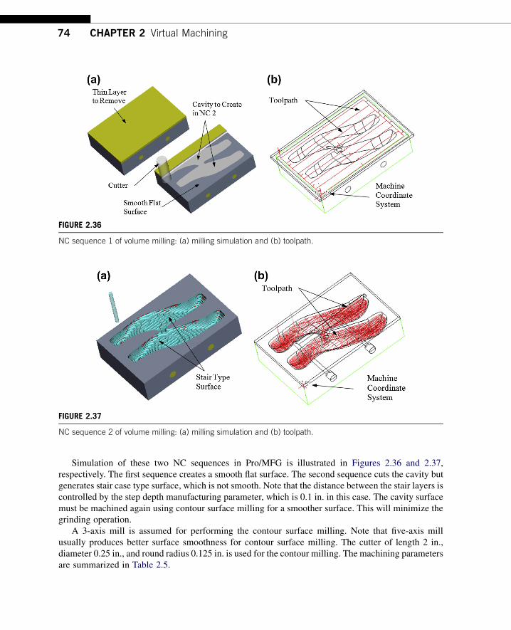
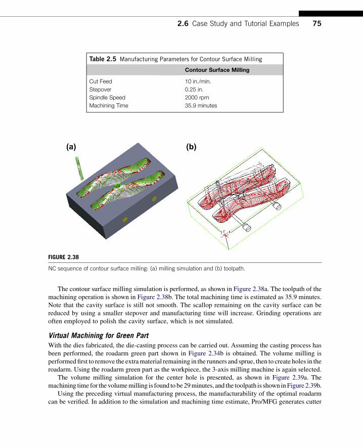
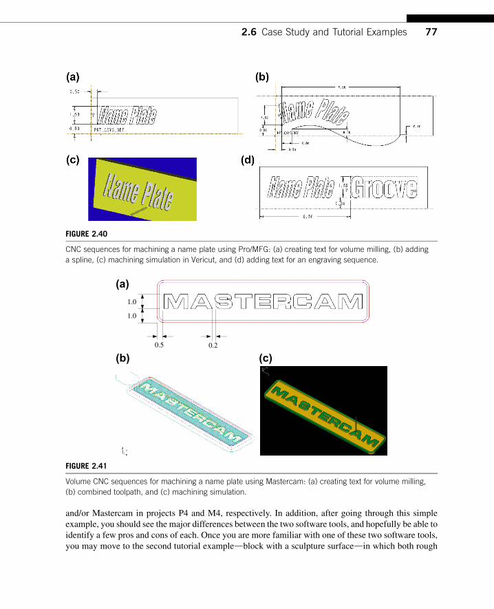
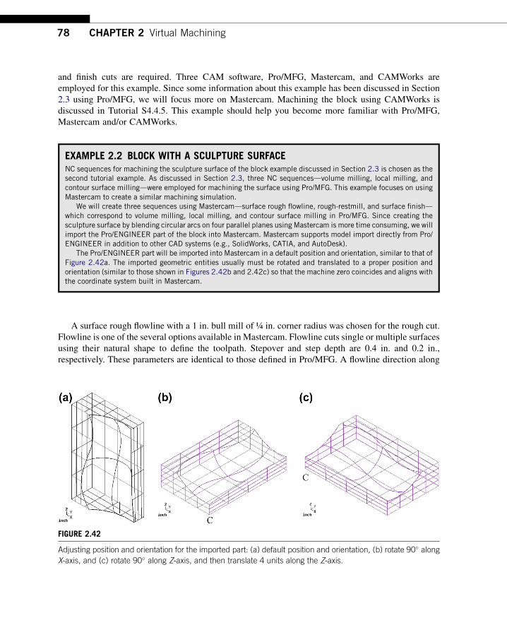

(a) (b)
FIGURE 244
Surface rough restmill machining in Mastercam (a) toolpath and (b) machining simulation
(a) (b)
FIGURE 245
Surface finish-scallop machining in Mastercam (a) toolpath and (b) machining simulation
80 CHAPTER 2 Virtual Machining
This is because a very small maximum stepover (005 in) is specified for the finish cut Asa result the overall machining time estimated is 7 hours and 18 minutes as reported byMastercam
27 SUMMARYIn this chapter we discussed the subject of virtual machining including NC part programming virtualmachining simulations simulation software that is commercially available as well as a case study andtutorial examples In addition we briefly addressed the practical aspects in CNC machining includingjigs and fixtures cutters and machining parameters and steps in operating HAAS mini-mill We hopethis chapter has helped you become more familiar with the subject With more practice you shouldbecome more confident and competent in using virtual machining simulation tools to address the
Questions and exercises 81
manufacturability of the product and obtain reasonable machining time estimates and required setup tosupport product design
In the next chapter we will introduce the topic of toolpath generation which is the backbone ofvirtual machining simulation It should provide you with a more in-depth understanding on the factorsthat contribute to the CNC toolpath generated in virtual machining simulation For those who areconducting research relevant to virtual machining or toolpath generation Chapter 3 should serve wellas an introductory article for understanding toolpath generation For practicing engineers the chapteroffers behind-the-scene operations in the calculation of cutter location data and parameters that affectthat data Knowledge acquired will help you diagnose problems encountered on the machined surfaces(eg gaging)
In the remaining chapters of this book we will describe other pertinent technology that supportsaddressing the manufacturing issues from design perspectives including sheet forming simulation(Chapter 4) rapid prototyping (Chapter 5) and manufacturing cost estimates (Chapter 6) CNCmachining discussed in this chapter and rapid prototyping in Chapter 5 offer a means to support fastprototyping in product development These chapters should provide you with a very good under-standing on the essential topics involved in product manufacturing using advanced computer-aidedtechnology
QUESTIONS AND EXERCISES
21 Write a CNC program (with explanations for each block) for a HAAS mill to machine a 4 in
425 in 25 in aluminum block for the part (design model) shown in the following image andtable Choose your own cutters (from those shown in the table) and cutting parameters (step depthand stepover) with ldquocommon senserdquo Note that you need to use tool radius compensation for alltoolpaths Calculate the overall cutting time
Size (inches) Type Length (inches)18 Ball-nose 0375 316 Ball-nose 1000 14 Ball-nose 0625 12 Ball-nose 2000 18 Flat-end 0375 316 Flat-end 0475 14 Flat-end 0500 14 Flat-end 0875 516 Flat-end 0600 38 Flat-end 0600 12 Flat-end 1000 12 Flat-end 1500
22 Verify your NC program of 21 using an adequate software tool Search and find a softwareprogram that takes your NC program and simulates the NC sequence
82 CHAPTER 2 Virtual Machining
23 Write a NC program to cut a 025 in-deep pocket on a 3 in 3 in 05 in block shown in thefollowing figure The cutter diameter is 05 in Note that the cutter will cut inside of the pocket bymoving along the pocket boundary only one time which will leave some material uncut Youmust use tool radius compensation for the NC codes Identify the uncut area Also sketch yourtoolpath which must start from point A
Point A
B
24 Write a complete APT (Automatically Programmed Tools) program to cut a 025 in-deep pocketon a 3 in 3 in 05 in block shown in the following figure The cutter diameter is 075 in Notethat spindle speed is 580 and feedrate is 23 Note that the cutter must start from point SP andreturn to SP after the cut
P1
SP
P4 P3
P2
L3
L1
L2 L4
25 Use ProMFG CAMWorks or Mastercam (or other CAM software you have access) to machinethe design model shown below (left) from a workpiece of 12 in8 in45 in (show below right)Note that at least two NC sequences are needed face milling that removes top layer of 05 in deepfrom top surface of the workpiece then pocket milling that cuts the pocket
Questions and exercises 83
26 Design and machine a nameplate on a 3 in12 in ⅜ in Plexiglas workpiece using theHAAS CNC mill (or other mill you have access) Note that you can design your plateusing ProMFG (CAMWorks or Mastercam) directly write your CNC codes using HAAScommands or any other software tools that you found This will be a combination of textengraving volume and trajectory milling and picturelogo carving The following is whatyou need to submit for grade Please BE VERY CREATIVE(a) Your design describe it briefly in a few sentences and use pictures for illustration(b) Your CNC codes with explanations (only important blocks no need to submit the entire NC
program)(c) Final machined nameplate (if applicable)(d) Two significant things that you learned from using the mill
ReferencesChang T-C Wysk RA Wang H-P 1998 Computer-Aided Manufacturing second ed Prentice HallKalpakjian S Schmid SR 2010 Manufacturing Engineering and Technology sixth ed Prentice HallKrar S Gill A Smid P 2010 Technology of Machine Tools seventh ed McGraw-HillOberg E Jones F Horton H Ryffel H McCauley C 2012 Machineryrsquos Handbook twentyninth ed
Industrial PressSarma R Dutta D 1997 An integrated system for NC machining of multi-patch surfaces Computer-Aided
Design 29 (11) 741ndash749Smid P 2000 CNC Programming Handbook second ed Industrial Press Inc 200 Madison Avenue New York
NY 10016-4078
84 CHAPTER 2 Virtual Machining
APPENDIX A SAMPLE ADDRESS CODES
A Fourth-axis rotary motion The A address character is used to specify motion forthe optional fourth A axis It specifies an angle indegrees for the rotary axis It is always followed bya signed number and up to three fractional decimalpositions
B Fifth-axis rotary motion The B address character is used to specify motion forthe optional fifth B axis It specifies an angle indegrees or the rotary axis It is always followed bya signed number and up to three fractional decimalpositions
C Auxiliary external rotary axis The C address character is used to specify motion forthe optional external sixth C axis It specifies an anglein degrees for the rotary axis It is always followed bya signed number and up to three fractional decimalpositions
D Tool diameter selection The D address character is used to select the tooldiameter or radius used for cutter compensation
F Feedrate The F address character is used to select the feedrateapplied to any interpolation functions including pocketmilling and canned cycles
G Preparatory functions (G-codes) The G address character is used to specify the type ofoperation to occur in a block
H Tool length offset selection The H address character is used to select the tool lengthoffset entry from the offsetrsquos memory
I J K Canned cycle and circular optionaldata
The I J and K address character is used to specify dataused for some canned cycles and circular motions
L Loop count for repeated cycles The L address character is used to specify a repetitioncount for some canned cycles and auxiliary functions
M Code miscellaneous functions The M address character is used to specify an M-codefor a block These codes are used to controlmiscellaneous machine functions
N Number of block The N address character is entirely optional It can beused to identify or number each block of a program
R Canned cycle and circular optionaldata
The R address character is used in canned cycles andcircular interpolation
S Spindle speed command The S address character is used to specify the spindlespeed
T Tool selection code The T address character is used to select the tool for thenext tool change
X Y Z Linear X- Y- and Z-axis motions The X- Y- and Z-address characters are usedto specify motion for the X-axis It specifiesa position or distance along the X- Y- and Z-axesrespectively
Appendix B Sample G- and M-Codes 85
APPENDIX B SAMPLE G- AND M-CODES
G-Code Function
G00 Rapid Motion
G01 Linear Interpolation Motion
G02 CW Interpolation Motion
G03 CCW Interpolation Motion
G04 Dwell
G12 CW Circular Pocket Milling
G13 CCW Circular Pocket Milling
G17 XY Plane Selection
G18 ZX Plane Selection
G19 YZ Plane Selection
G20 Select Inches
G21 Select Metric
G28 Return to Reference Point
G29 Return From Reference Point
G40 Cutter Comp Cancel
G41 2D Cutter Compensation Left
G42 2D Cutter Compensation Right
G43 Tool Length Compensation thornG44 Tool Length Compensation G47 Text Engraving
G49 G43G44G143 Cancel
G80 Canned Cycle Cancel
G81 Drill Canned Cycle
G82 Spot Drill Canned Cycle
G83 Normal Peck Drill Canned Cycle
G84 Tapping Canned Cycle
G85 Boring Canned Cycle
G86 BoreStop Canned Cycle
G87 BoreStopManual Retract Canned Cycle
G88 BoreDwellManual Retract Canned Cycle
G89 BoreDwell Canned Cycle
G90 Absolute
G91 Incremental
G98 Initial Point Return
G99 R Plane Return
M-Code Function
M00 Stop Program
M01 Optional Program Stop
M02 Program End
M03 Spindle Forward
M04 Spindle Reverse
M05 Spindle Stop
M06 Tool Change
M08 Coolant On
M09 Coolant Off
M30 Prog End and Rewind
M97 Local Sub-Program Call
M98 Sub Program Call
M99 Sub Program Return or Loop
86 CHAPTER 2 Virtual Machining
APPENDIX C HAAS MINI-MILLWe use a HAAS mini-mill as an example to illustrate detailed procedures and setups for those who areinterested in learning more andor those have access to a HAAS mini-mill
Basic Machine ConfigurationThe HAAS mini-mill is a 3-axis mill with a work envelop 16 in 12 in 10 in as shown inFigure 246 The maximum spindle speed and rapid feed are 6000 rpm and 600 ipm (inmin)respectively There are 10 tool changers in the tool pocket (or tool turret) which are able to hold 10
(b)(a)
Jig table
Tool Pockets
Spindle
Coolant tube
FIGURE 246
HAAS mini-mill (a) exterior and (b) interior
Appendix C HAAS Mini-Mill 87
different cutters The mini-mill is relatively less expensive and is affordable for academia and a smallshop All stock material that will be machined must be rigidly mounted to the jig table The machinistmust be aware of oversized stock material extra jig components (eg clamps and vises) andextended-length milling tools to avoid collision with the spindle
Prestart and Power-UpBefore powering up the mill there are a few things to checkdfor example coolant liquid level airpressure and so on
Power-Up
The green button at the top left corner of the control panel (Figure 247) will turn on the mill Themachine will boot up and an alarm message will appear Not to worry this is normal it simply meansthat the mill has not gone through a calibration process yet Press the ZERO RET button on the controlpanel then the AUTO ALL AXES button to calibrate the machine Make sure the millrsquos door is closedThe table will move to the nearest left corner with the spindle retracted to the highest point Themachine is now powered up and ready for user control
The HAAS mill uses six modes of operation to complete the tasks needed for milling a part theyare circled in Figure 247 (left most column) The user must enter one of these modes in order to useany of the four action buttons to the right
Moving the Jig TableEnter the jog mode by pressing the HANDLE JOG button (Figure 247) Press the 1100 button thiswill move the table 01 inches per tick of the jog handle in the corresponding direction The user canspecify a smaller increment using the remaining action buttons
POWER ONOFF
SPINDLE LOAD
E - STOP
JOG HANDLE
FIGURE 247
HAAS mini-mill control panel with action buttons
(a) (b)
FIGURE 248
Moving the jig table (a) axis jog buttons and (b) jog handle
88 CHAPTER 2 Virtual Machining
Press the thornX or X button (Figure 248a) The buttons surrounding the JOG LOCK button are forthe user to select which axis is to be moved Rotate the jog handle (Figure 248b) in the clockwise orpositive direction to move the table right Position the table so that it will be easier to mount yourworkpiece
Tool LoadingLoading cutters is one of the most important steps in presetting a CNC machining sequence You maycollect all the needed cutters and follow the steps to load them to the mill First enter the MDI mode(Manual Data Input) (see Figure 247) Press ATC FWD or ATC REVuntil tool one is in the spindle Getthe tool to be loaded and insert it in the spindle as far as it will go Press and hold the TOOL RELEASEbutton (see Figure 249) A blast of air will shoot out of the spindle to clear any debris Push the tool upinto the spindle and release the button
FIGURE 249
Tool release and program reset
FIGURE 250
Work coordinate list
Appendix C HAAS Mini-Mill 89
Work Coordinate SetupThe work coordinate must be placed on the stock material in the same place that you have set it inProMFG or Mastercam (or other CAM software) The HAAS mini-mill has 14 different workcoordinates that can be set independently of one another (see Figure 250) The OFSET button can betoggled to view these coordinate offsets (see Figure 251) While the screen is displaying the offsets forthe coordinates use the up and down arrows in the center of the control panel to select the X-axis forthe coordinate system the user will be working in The default coordinate system is G54
Axis Part ZeroNow we are setting the machine zero (or axis part zero) using the following steps
1 Load a drill chuck with an edge-finding tool (Figure 252) into the spindle2 Enter HANDLE JOG mode (see Figure 247) Note that the display on the screen will not change3 Turn the spindle clockwise using the CW button (Figure 253)4 Move the edge finder to the X position of the part using the jog handle (Figure 254)5 Press PART ZERO SET (Figure 249) to zero the X-axis The Y-axis should now be highlighted in
the display
FIGURE 251
Display menu
FIGURE 253
Spindle and feed control
FIGURE 254
Using edge finder to setup X-axis
FIGURE 252
Feeler gage and edge finder
90 CHAPTER 2 Virtual Machining
G90 G54 G00 X0 Y0
FIGURE 255
X-Y coordinate zero check
Appendix C HAAS Mini-Mill 91
Repeat steps 3 through 5 to zero the Y-axis The Z-axis will be set after all the tools needed formilling are loaded
Z-Axis OffsetOnce all tools are loaded into the tool changer the lengths of each must be measured First the Z-axis isoffset using a feeler gage (Figure 256)
1 Advance tool 1 into the spindle by enteringMDImode and typing T1 then press theWRITE buttonin the lower right of the control panel
2 Press ATC FWD to move directly to tool 2 Be sure the part is out of the way before the tool changewhen using extended-length tools
3 Check the X- and Y-axis zero points by entering the contents of Figure 255 into MDI modeThe block G54 may be changed if the user selects a different coordinate system (eg G55 G59)
4 Close the door and press CYCLE START (Figure 248b) This will load into memorywhich coordinate system you will be using as well as move the table to the X-Y zero position
5 Position the tool over the area in which the Z offset can be measured there must be room for thefeeler gage as well (Figure 256)
6 Press OFSET and use the arrow keys to highlight the Z-axis offset under the proper coordinatesystem
7 Press PART ZERO SET (Figure 249) to zero the Z-axis
FIGURE 256
Z-axis offset and tool length offset
92 CHAPTER 2 Virtual Machining
Tool Offset MeasureThe lengths of each tool will be based on that of tool 1 Since the Z-axis is zeroed using tool 1 thelength offset for tool 1 should be zero Check this by toggling the OFSET button (Figure 251) todisplay the tool offset lengths Highlight tool 1 and press TOOL OFSET MESUR (Figure 249) thevalue should become zero
Offsetting ToolsDo the following to use the offsetting tools
1 Retract the tool using the handle jog Z-axis positive direction2 Press ATC FWD to the next tool and handle jog it down to the Z zero surface using the feeler gage3 Highlight the tool in the offset display and press TOOL OFSET MESUR (Figure 249) The value
that appears will be the difference in length of the tool in the spindle to tool 24 Repeat previous steps until all tools are measured
The thickness of the feeler gage must now be subtracted from the Z-axis height Toggle the OFSETdisplay to the work coordinate offsets Highlight the Z-axis and type in the negative of the feeler gagethickness and press WRITE
Loading a ProgramOnce a program is loaded using the following steps it automatically becomes the selected program themill will run if the cycle start button is pressed
1 Press LIST PROG (Figure 247) to start the program control mode programs are downloadeduploaded and deleted from this mode
2 Type in the program number starting with the letter ldquoOrdquo before the number3 Press WRITE4 Press RECV RS232 (Figure 247) to prepare the mill to receive a file from the connected computer5 Start the NCnetLite program on the computerrsquos desktop6 Click the green thumbs up button to connect to the mill (Figure 257)7 Click the transmit button and select the file to send The file is automatically sent after the OK
button is selected
THUMBS UP TRANSMIT
FIGURE 257
Loading NC program
Appendix C HAAS Mini-Mill 93
A program can be edited if the user enters the EDIT mode It is recommended that onlysmall changes be made in this mode due to the limited ability to verify the toolpaths after thispoint
Running a ProgramAfter doing the following steps do not increase the rapid feed until the program has verified that thefirst few cuts are correct
1 In the LIST PROG mode highlight the program to be run then press SELECT PROG (Figure 247)2 Enter the MEM mode and change the display by pressing CURNT COMDS (Figure 253)3 Reduce the rapid motion to 5 (Figure 253) and run the program by pressing CYCLE START
(Figure 248b)
If the cuts are not correct press the FEED HOLD (Figure 248b) button to stop the table feed thenpress RESET to turn off the spindle and coolant (Figure 249) Handle jog the tool out of the part andcall the shop supervisor for assistance
Once the program has completed remove the part and tools then clean the mill from any materialchips or spilled coolant
- 2 Virtual Machining
-
- 21 Introduction
- 22 NC Part Programming
-
- 221 Basics of NC Machines
- 222 Basic Concept of Part Programming
- 223 Computer-Assisted Part Programming
- 224 CADCAM Approach
-
- 23 Virtual Machining Simulations
-
- 231 Basic Machining Simulations
- 232 Advanced Machining Simulations
- 233 Turning Simulations
-
- 24 Practical Aspects in CNC Machining
-
- 241 Jigs and Fixtures
- 242 Cutters and Machining Parameters
- 243 Setting a CNC Sequence
-
- 25 Commercial Machining Simulation Software
-
- 251 General-Purpose Machining Software
- 252 Special-Purpose Machining Software
-
- 26 Case Study and Tutorial Examples
-
- 261 Case Study
- 262 Tutorial Examples
-
- 27 Summary
- Questions and Exercises
- References
- Appendix A Sample Address Codes
- Appendix B Sample G- and M-Codes
- Appendix C HAAS Mini-Mill
-
- Outline placeholder
-
- Basic Machine Configuration
- Prestart and Power-Up
-
- Power-Up
-
- Moving the Jig Table
- Tool Loading
- Work Coordinate Setup
- Axis Part Zero
- Z-Axis Offset
- Tool Offset Measure
- Offsetting Tools
- Loading a Program
- Running a Program
-
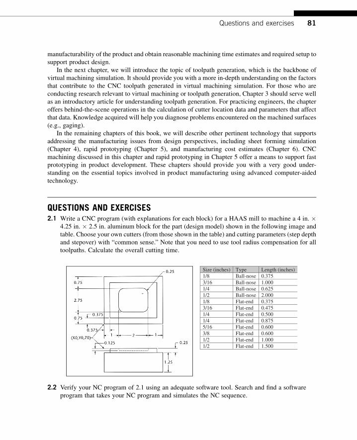
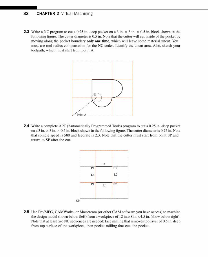
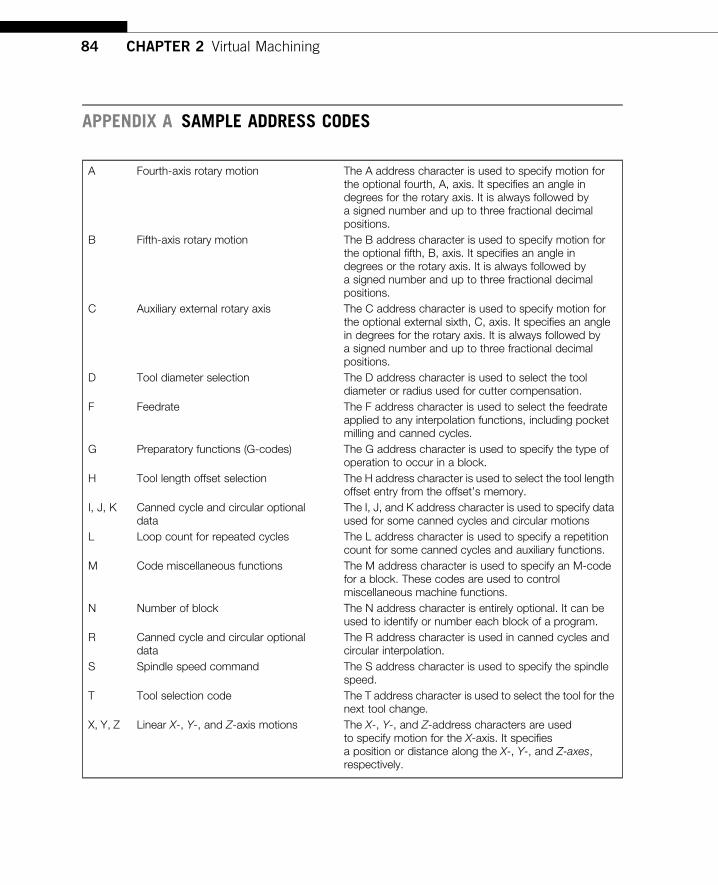
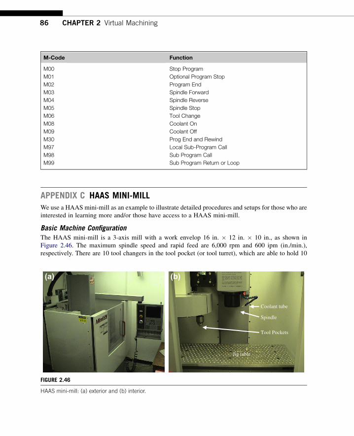
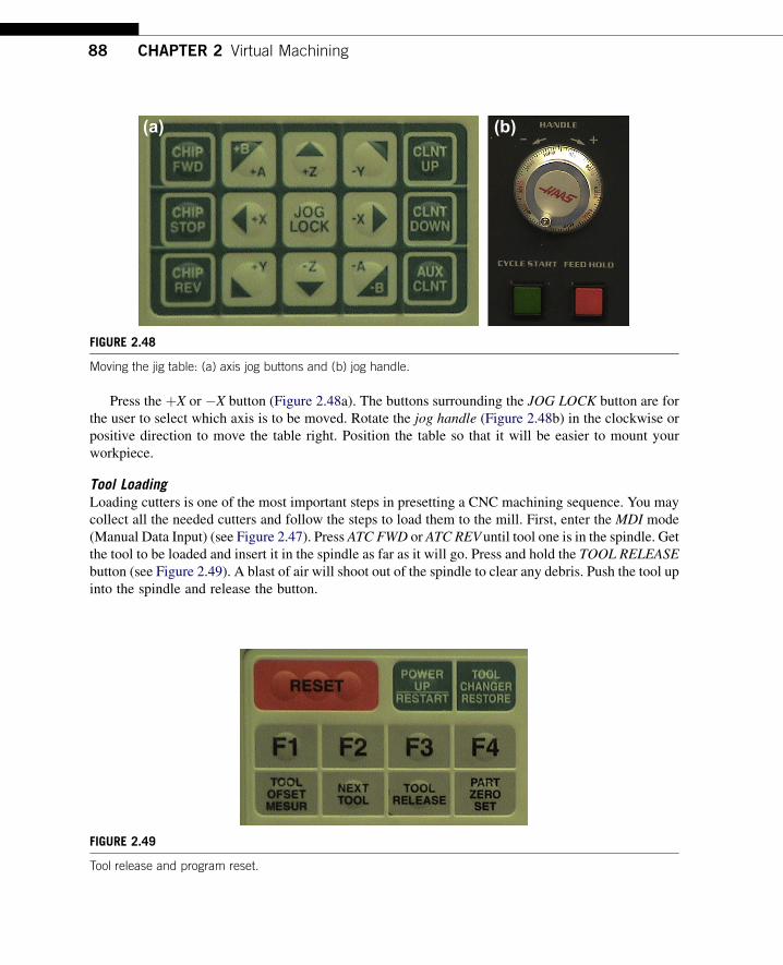
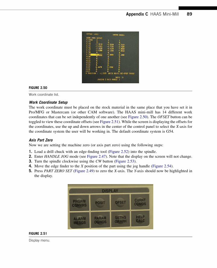
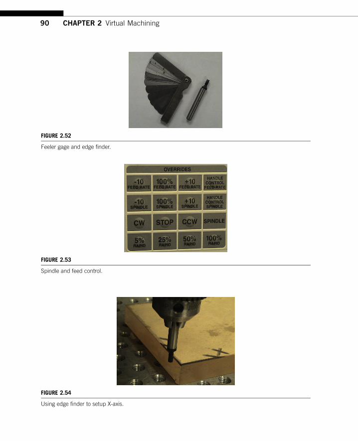
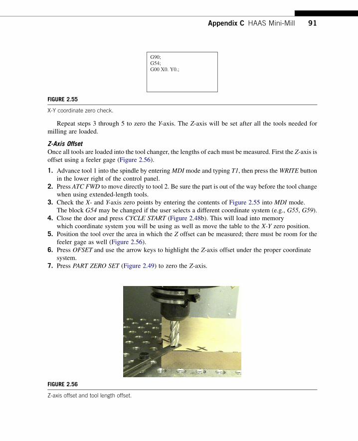