product overview mbbr wwtp - mak water product over… · overview mak water’s moving bed...
TRANSCRIPT

PRODUCT
OVERVIEW
MBBR WWTP

OverviewMAK Water’s Moving Bed Bioreactor (MBBR) waste water
treatment plants are designed to treat domestic strength
sewage, to achieve Class C treated effluent, suitable for reuse in
“risk category low” applications or for disposal via spray field.
With the addition of the optional Tertiary Filtration & Sterilization
module, Class A treated effluent, suitable for reuse in “risk
category medium” applications, can be achieved.
Key Advantages:
• High quality Australian designed and built
• Containerised system minimises site installation work
• Compact /modular design minimises footprint and
maximises scalability
• Factory tested prior to delivery
• Robust and simple to operate and maintain
• Fully automated system allows lower operator skill level
• Fully enclosed bioreactor minimises odour
MAK Containerised MBBR with Class A Polishing
Plant + Balance Tank, Treated Effluent Tank and
Irrigation Pump Set
MAK Containerised MBBR undergoes FAT in
MAK’s Workshop

Overview
The Moving Bed Bioreactor (MBBR) system, utilises a biological treatment process whereby highly
aerated effluent flows through inert media that is completely submerged; fixed microbial film reduces the
BOD and ammoniacal content of the effluent.
The treatment process includes influent screening (where required), biological degradation
(aerobic/anaerobic treatment), clarification and effluent sterilization (chlorination).
The optional “Class A” Filtration & Sterilization process includes multimedia filtration followed by
secondary chlorination via tank recirculation and residual trim sodium hypochlorite dosing.
Additional treatment steps for nutrient removal (T-N & T-P) and sludge de-watering systems may be
added as required to suit influent quality and/or treated effluent quality requirements. The MAK MBBR
plants are containerised systems for easy deployment to remote locations.

Overview
Parameter Unit Influent Effluent (Class C) Effluent (Class A)
BOD mg/L 150~500 <20
TSS mg/L 150~400 <30 <5
T-N mg/L <50 <40 (lower TN available upon request)
T-P mg/L <15 <10 (lower TN available upon request)
Turbidity NTU - - <5
E.Coli CFU/100 mL - <1,000 <10
Free Chlorine mg/L - 0.2~2
The following table summarises typical influent and treated effluent values.
Additional equipment and/or de-rating of name plate hydraulic capacity may apply where higher influent
TN/TP loading and/or lower treated effluent TN/TP values are required.

Process Steps
Balance
Tank(s)
Raw
sewage
Balance Tank
The Balance Tank is designed to handle peak flows and allow a pre-determined and controlled flow for
subsequent treatment. The waste water is temporarily stored in the Balance Tank before being pumped
to Primary Tank 1. The flow rate is set using a flow control valve; excess flow is returned to the same
tank to maintain homogeneity of influent feed.
The Balance Tank level is regulated by 3 float-type level switches.

Process Steps
Inlet screening
For larger flow rates (>75 m3/day), the plant is provided with a sewage inlet screen, which removes
inorganic foreign objects, which have the potential to cause damage downstream equipment.
The inlet screen is typically mounted above the MBBR container; screened sewage gravity flows into the
plant, screenings are washed, dewatered and deposited down a chute into a skip/bin for disposal.
Inlet
Screen-
ing
Waste
Bin
Balance
Tank(s)
Raw
sewage
Process Steps
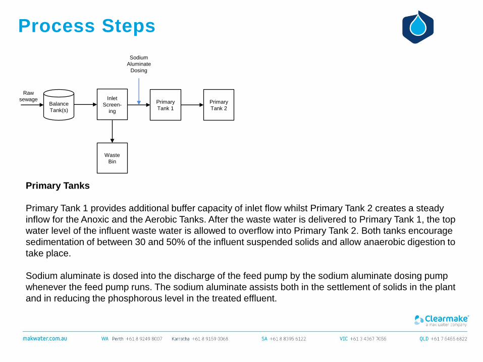
Primary Tanks
Primary Tank 1 provides additional buffer capacity of inlet flow whilst Primary Tank 2 creates a steady
inflow for the Anoxic and the Aerobic Tanks. After the waste water is delivered to Primary Tank 1, the top
water level of the influent waste water is allowed to overflow into Primary Tank 2. Both tanks encourage
sedimentation of between 30 and 50% of the influent suspended solids and allow anaerobic digestion to
take place.
Sodium aluminate is dosed into the discharge of the feed pump by the sodium aluminate dosing pump
whenever the feed pump runs. The sodium aluminate assists both in the settlement of solids in the plant
and in reducing the phosphorous level in the treated effluent.
Inlet
Screen-
ing
Waste
Bin
Balance
Tank(s)
Raw
sewage Primary
Tank 1
Sodium
Aluminate
Dosing
Primary
Tank 2

Process Steps
Anoxic Tank
The influent is allowed to overflow from Primary Tank 2 to the Anoxic Tank. The Anoxic Tank allows
nitrate-specific bacteria to use nitrate (NO3) as an oxygen source and a nutrient in a process called
denitrification. This activity helps to remove nitrogen based pollutants such as urea and ammonia by
converting them into nitrate and nitrite before releasing them as nitrogen gas into the atmosphere. The
tank is enriched with returned activated sludge (RAS) from the Clarifier to provide a plentiful supply of
food for the bacteria. The partially treated effluent from the Anoxic Tank contains approximately 65% of
the pollution load of the original sewage influent entering the waste water plant.
Where enhanced nutrient (TN/TP) removal is required, an additional food source for the bacteria is
provided by way of sucrose dosing into the anoxic tank.
Inlet
Screen-
ing
Waste
Bin
Balance
Tank(s)
Raw
sewage Primary
Tank 1
Sodium
Aluminate
Dosing
Primary
Tank 2
Anoxic
Tank
Sucrose
Dosing
OPTIONAL

Process Steps
Aerobic Tank
The influent is allowed to overflow from the Anoxic Tank to the Aerobic Tank where it is aerated. Air is
introduced into the Aerobic Tank by the Biological Air Blower through air diffusers located beneath the
submerged media.
The submerged media has a large surface area, allowing bacteria and other micro-organisms to thrive
and form a biological film. These micro-organisms utilise the dissolved oxygen in the air bubbles in the
waste water to consume dissolved matter and by so doing remove a majority of the colloidal
contaminants present in the waste water by converting them into carbon dioxide and biological floc.
Inlet
Screen-
ing
Waste
Bin
Balance
Tank(s)
Raw
sewage Primary
Tank 1
Sodium
Aluminate
Dosing
Primary
Tank 2
Anoxic
Tank
Sucrose
Dosing
OPTIONAL
Aerobic
Tank w/
media
Air lift recycle
Aeration
blower
Caustic
Dosing
OPTIONAL
Air Lift
Pumps
blower

Process Steps
Aerobic Tank
Floc is then allowed to settle in the Clarifier from where it is removed, thereby reducing the accumulation
of sludge. Friction from the air bubbles further serves to scour and release dead biomass from the
media. This Aerobic Tank is partially divided by a baffle so as to prevent under-aerated waste water from
prematurely moving to the next stage in the treatment process. This baffle also serves to alter the flow
direction such that the partially treated waste water will make intimate contact with the submerged
media before entering the Clarifier.
Where enhanced nutrient (TN/TP) removal is required, pH correction is provided by way of caustic
dosing into the air lift recycle to the anoxic tank.
Inlet
Screen-
ing
Waste
Bin
Balance
Tank(s)
Raw
sewage Primary
Tank 1
Sodium
Aluminate
Dosing
Primary
Tank 2
Anoxic
Tank
Sucrose
Dosing
OPTIONAL
Aerobic
Tank w/
media
Air lift recycle
Aeration
blower
Caustic
Dosing
OPTIONAL
Air Lift
Pumps
blower
Aeration
blower
Air lift recycle
Process Steps
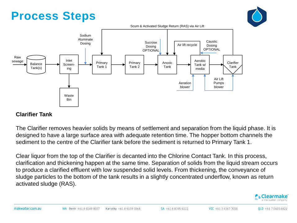
Clarifier Tank
The Clarifier removes heavier solids by means of settlement and separation from the liquid phase. It is
designed to have a large surface area with adequate retention time. The hopper bottom channels the
sediment to the centre of the Clarifier tank before the sediment is returned to Primary Tank 1.
Clear liquor from the top of the Clarifier is decanted into the Chlorine Contact Tank. In this process,
clarification and thickening happen at the same time. Separation of solids from the liquid stream occurs
to produce a clarified effluent with low suspended solid levels. From thickening, the conveyance of
sludge particles to the bottom of the tank results in a slightly concentrated underflow, known as return
activated sludge (RAS).
Inlet
Screen-
ing
Waste
Bin
Balance
Tank(s)
Raw
sewage Primary
Tank 1
Sodium
Aluminate
Dosing
Primary
Tank 2
Anoxic
Tank
Sucrose
Dosing
OPTIONAL
Aerobic
Tank w/
media
Caustic
Dosing
OPTIONAL
Clarifier
Tank
Scum & Activated Sludge Return (RAS) via Air Lift
Air Lift
Pumps
blower

Aeration
blower
Air lift recycle
Process Steps
Chlorine Contact Tank
The influent is allowed to overflow from the Clarifier to the Chlorine Contact Tank. The Chlorine Contact
Tank contains chlorine in tablet form and it is designed to provide 30 minutes minimum contact time for
effective disinfection of the influent with chlorine, a powerful disinfectant.
This is a process whereby chlorine compounds are added to the treated waste water for the purpose of
pathogen reduction. Calcium hypochlorite tablets are in constant contact with the effluent to ensure that
the effluent is safe for disposal.
Inlet
Screen-
ing
Waste
Bin
Balance
Tank(s)
Raw
sewage Primary
Tank 1
Sodium
Aluminate
Dosing
Primary
Tank 2
Anoxic
Tank
Sucrose
Dosing
OPTIONAL
Aerobic
Tank w/
media
Caustic
Dosing
OPTIONAL
Clarifier
Tank
Scum & Activated Sludge Return (RAS) via Air Lift
Air Lift
Pumps
blower
Chlorine
Contact
Tank
Chlorine
Tablets
Aeration
blower
Air lift recycle
Process Steps
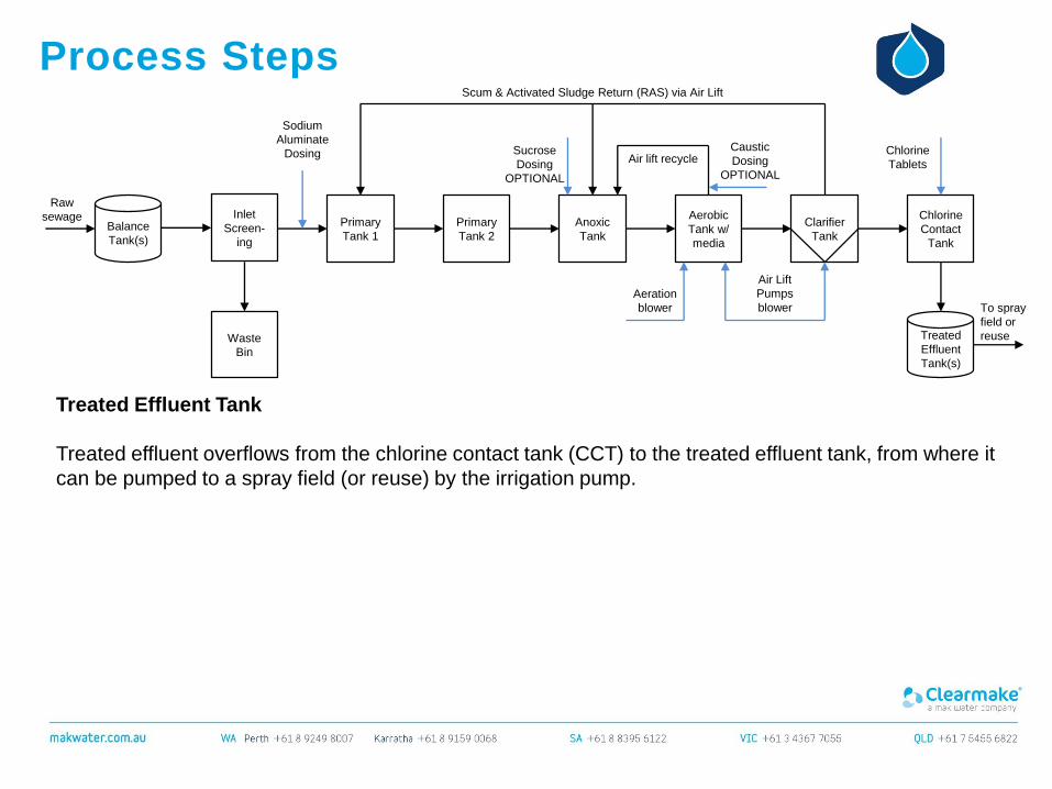
Treated Effluent Tank
Treated effluent overflows from the chlorine contact tank (CCT) to the treated effluent tank, from where it
can be pumped to a spray field (or reuse) by the irrigation pump.
Inlet
Screen-
ing
Waste
Bin
Balance
Tank(s)
Raw
sewage Primary
Tank 1
Sodium
Aluminate
Dosing
Primary
Tank 2
Anoxic
Tank
Sucrose
Dosing
OPTIONAL
Aerobic
Tank w/
media
Caustic
Dosing
OPTIONAL
Clarifier
Tank
Scum & Activated Sludge Return (RAS) via Air Lift
Air Lift
Pumps
blower
Chlorine
Contact
Tank
Chlorine
Tablets
Treated
Effluent
Tank(s)
To spray
field or
reuse

Aeration
blower
Air lift recycle
Process Steps
Sludge Removal via Pump Out
Periodically, sludge will need to be removed from the system via a sludge pump truck.
Inlet
Screen-
ing
Waste
Bin
Balance
Tank(s)
Raw
sewage Primary
Tank 1
Sodium
Aluminate
Dosing
Primary
Tank 2
Anoxic
Tank
Sucrose
Dosing
OPTIONAL
Aerobic
Tank w/
media
Caustic
Dosing
OPTIONAL
Clarifier
Tank
Scum & Activated Sludge Return (RAS) via Air Lift
Air Lift
Pumps
blower
Chlorine
Contact
Tank
Chlorine
Tablets
Treated
Effluent
Tank(s)
To spray
field or
reuseSludge
removal via
pump truck

Aeration
blower
Air lift recycle
Process Steps
Sludge Storage & Removal via Pump Out
Where site conditions dictate, a sludge pump and sludge storage tank can be provided. This enables
larger volumes of sludge to be stored onsite, thereby extending the interval between sludge pump out
via pump truck.
The primary advantage of the sludge tank is thus the ability to store a sufficient volume of sludge to
completely fill a pump truck, and thereby reduce sludge trucking costs.
It is worth noting that the volume of the sludge tank need not be larger than the capacity of the sludge
pump truck.
Inlet
Screen-
ing
Waste
Bin
Balance
Tank(s)
Raw
sewage Primary
Tank 1
Sodium
Aluminate
Dosing
Primary
Tank 2
Anoxic
Tank
Sucrose
Dosing
OPTIONAL
Aerobic
Tank w/
media
Caustic
Dosing
OPTIONAL
Clarifier
Tank
Scum & Activated Sludge Return (RAS) via Air Lift
Air Lift
Pumps
blower
Chlorine
Contact
Tank
Chlorine
Tablets
Treated
Effluent
Tank(s)
To spray
field or
reuseSludge
Tank
Sludge
removal via
pump truck

Scum & Activated Sludge Return (RAS) via Air Lift
Aeration
blower
Air lift recycle
Process Steps
Sludge Storage and Dewatering
For larger plants, onsite sludge dewatering may be considered to vastly reduce waste trucking volumes.
One economical way to achieve this is via a sludge press.
Polymer dosing is also required in most cases.
Dewatered sludge (spade-able cake) is deposited into a skip bin for disposal offsite.
The filtrate (supernatant) can be returned to the head of the process into primary tank 1, or to the
balance tank.
Inlet
Screen-
ing
Waste
Bin
Balance
Tank(s)
Raw
sewage Primary
Tank 1
Sodium
Aluminate
Dosing
Primary
Tank 2
Anoxic
Tank
Sucrose
Dosing
OPTIONAL
Aerobic
Tank w/
media
Caustic
Dosing
OPTIONAL
Clarifier
Tank
Air Lift
Pumps
blower
Chlorine
Contact
Tank
Chlorine
Tablets
Treated
Effluent
Tank(s)
To spray
field or
reuseSludge
Tank
Dewatered
sludge cake
to skip bin
Sludge
Press
Polymer Dosing

Multi-
media
Filter
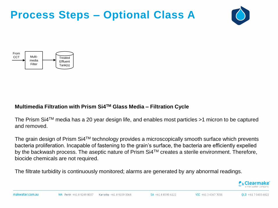
Process Steps – Optional Class A
Multimedia Filtration with Prism Si4TM Glass Media – Filtration Cycle
The “Class C” effluent from the CCT is pumped through a media filter to remove suspended solids,
producing “Class A” effluent ,with suspended solid less than 5 mg/L. The filtrate discharges into the
treated effluent tank.
The media used inside this media filter is Prism Si4TM. Prism Si4TM glass filtration technology is a
uniquely processed glass based filter media is perfectly suited for wastewater filtration systems. Its
unique properties ensure the best permanent filtration performance.
Prism Si4TM has been engineered to combine the most advantageous features needed in a media
filtration system – high dirt loading capacity, very low pressure differential during operation, anti-fouling,
aseptic properties, anti-compaction properties & more.
From
CCT Treated
Effluent
Tank(s)
Multi-
media
Filter
Process Steps – Optional Class A
Multimedia Filtration with Prism Si4TM Glass Media – Filtration Cycle
The Prism Si4TM media has a 20 year design life, and enables most particles >1 micron to be captured
and removed.
The grain design of Prism Si4TM technology provides a microscopically smooth surface which prevents
bacteria proliferation. Incapable of fastening to the grain’s surface, the bacteria are efficiently expelled
by the backwash process. The aseptic nature of Prism Si4TM creates a sterile environment. Therefore,
biocide chemicals are not required.
The filtrate turbidity is continuously monitored; alarms are generated by any abnormal readings.
From
CCT Treated
Effluent
Tank(s)

Multi-
media
Filter
Process Steps – Optional Class A
Multimedia Filtration with Prism Si4TM Glass Media – Backwash Cycle
Automatic backwashing of the media filter is triggered when the pressure drop across the media filter
reaches a predetermined set point, or when the high turbidity alarm is triggered, or when the filtration
timer has elapsed.
The backwash pump draws water from the treated effluent tank. The dirty backwash wastewater can be
returned to the head of the process into primary tank 1, or to the balance tank.
From
CCT Treated
Effluent
Tank(s)
To Primary
Tank 1
Backwash

Hypo
Dosing
Multi-
media
Filter
Process Steps – Optional Class A
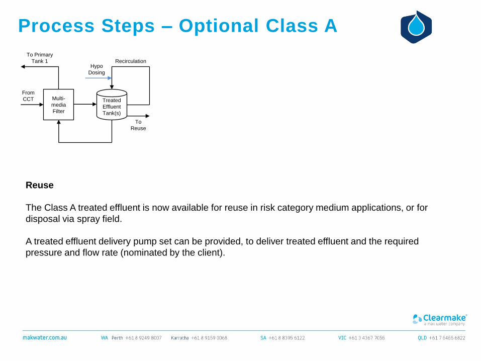
Treated Effluent Recirculation & PLC Controlled Hypochlorite Dosing (Residual Trim)
The treated effluent tank receives treated sewage from the MBBR WWTP. The tank should be
adequately sized to suit the storage capacity required by the site specific reuse application or disposal
pathway. This tank also provides the backwash water for the media filtration system.
The re-circulation pump circulates the treated effluent inside the treated effluent tank on a continuous
basis. The treated water re-circulation line is fitted with a chlorine analyser , which in turn controls the
dosing of sodium hypochlorite as required to maintain the residual set point (residual trim).
The treated effluent pH and free chlorine are continuously monitored; alarms are generated by any
abnormal readings.
From
CCT Treated
Effluent
Tank(s)
Recirculation
To Primary
Tank 1
Hypo
Dosing
Multi-
media
Filter
Process Steps – Optional Class A
Reuse
The Class A treated effluent is now available for reuse in risk category medium applications, or for
disposal via spray field.
A treated effluent delivery pump set can be provided, to deliver treated effluent and the required
pressure and flow rate (nominated by the client).
From
CCT Treated
Effluent
Tank(s)
Recirculation
To Primary
Tank 1
To
Reuse

Options – ClearAccessTM
Optional ClearAccessTM Remote Monitoring enables personnel
to view and operate the plant remotely. This saves time in
response to emergencies and assists local operators to
diagnose problems. It prevents unnecessary service call-outs
and improves reliability and plant uptime.
Key Functionality:
• Remotely view and operate the plant on your PC, smart
phone or tablet
• Automatic alerts (email or SMS) on alarm conditions
• Automatic report generated daily and emailed to your inbox
• Real time monitoring of process data, such as flow rates,
pressure and alarm conditions/status messages
• Password protected system with two login security levels
Inclusions:
• Additional electrical instrumentation (premium package)
• Additional PLC hardware and programming
• Programming of email alert system
NOTE: Remote monitoring requires an internet connection or
mobile network coverage (client to provide SIM card).
Process Support via ClearAccessTM
ClearAccessTM from your Smart Phone or Tablet

Understanding ReuseThe guidelines for the non-potable uses of recycled water seek to encourage beneficial and sustainable
use of recycled water and provide guidance for planning, design, approval, operation and monitoring of
recycled water supplies in regards to safeguarding public health and the environment.
Treated wastewater need not be considered a “waste” product to be discarded but a resource that can
have potential value if treated to a level that is ‘fit for purpose’, that is, recycled water must be treated to
a level that is suitable for its end use.
The level of treatment and monitoring that is required depends on the final application of the recycled
water. End uses have been split into 4 levels of ‘Exposure Risk’:
High Requires the highest quality of end use water and rigorous barriers, safeguards and
monitoring regimes
Medium Has moderate risk, usually reduced from a high risk category through barriers and
safeguards
Low Presents a low risk to human health (minimal contact)
Extra Low Negligible risk
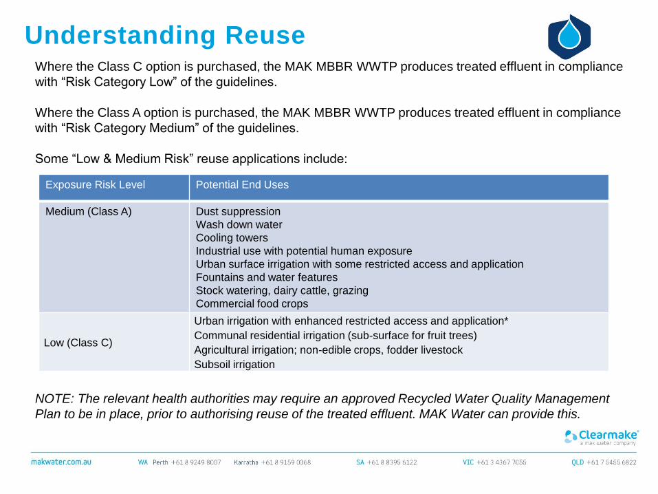
Understanding ReuseWhere the Class C option is purchased, the MAK MBBR WWTP produces treated effluent in compliance
with “Risk Category Low” of the guidelines.
Where the Class A option is purchased, the MAK MBBR WWTP produces treated effluent in compliance
with “Risk Category Medium” of the guidelines.
Some “Low & Medium Risk” reuse applications include:
Exposure Risk Level Potential End Uses
Medium (Class A) Dust suppression
Wash down water
Cooling towers
Industrial use with potential human exposure
Urban surface irrigation with some restricted access and application
Fountains and water features
Stock watering, dairy cattle, grazing
Commercial food crops
Low (Class C)
Urban irrigation with enhanced restricted access and application*
Communal residential irrigation (sub-surface for fruit trees)
Agricultural irrigation; non-edible crops, fodder livestock
Subsoil irrigation
NOTE: The relevant health authorities may require an approved Recycled Water Quality Management
Plan to be in place, prior to authorising reuse of the treated effluent. MAK Water can provide this.

Projects Experience
Project Roy Hill Iron Ore
Location Pilbara, Western Australia
Date 2014
Scope D&C, commissioning & operator training
Preparation of Recycled Water Quality
Management Plan
Capacity 35 m3/day
Influent Domestic strength sewage
Effluent Class Class A, with enhanced nutrient removal
Features Duty/standby pumps
Enhanced nutrient removal (TN < 10 mg/L)
Sludge pumps
Stand pipe for water truck filling (dust
suppression)
High spec engineering and vendor data
requirements