product overview - surf
TRANSCRIPT

Product Overview - SURF

Traditional six bolt Bend Restrictor:
• 30mm diameter bores up to 500 mm
• Max bending moments up to 60 kNm
• Max tensile load: 60 kN
• Min Bend Radius: 0.5 m to 6 m
• Stainless steel, superduplex or titanium bolting
• Finite Element Analysis Report on all restrictors

Fast-Lok Boltless Bend Restrictor (patent pending)
Key advantages:
1. Approximately 20% - 30% cost saving due to the removal of super duplex fasteners
2. Significantly reduced installation time onboard the vessel. Supergrip estimate that the boltless
assembly can be installed in approximately 20% of the time of a traditional system
3. The only bend restrictor in the market place that confirms with Norsok M-001 material selection.
The hinge pins are manufactured from Titanium grade-5 the only material considered corrosive
resistant.

Fast-Lok Boltless Bend Restrictor engineering and analysis

Full length supplied assembled with one pin Cable is laid into the assembled length and the first
Installed so that elements are hinged open knuckle is hinged closed and the locking pin installed

Installation engineer continues along the length simple pin installation closing each
subsequent knuckle and installing ONE pin
* Traditional units: Each individual knuckle installed around cable in two halves and SIX bolts installed and
tensioned to correct torque setting which is time consuming and can lead to galling and
seizure of stainless steel fasteners if not lubricated correctly

Dynamic Bend Stiffener:
• 30 mm diameter bores up to 300 mm
• Diameters up to 500 mm
• Length to be confirmed
• Steel, stainless steel or superduplex inserts
(manufactured in house)
• Stock products & bespoke designs

Polyurethane Ducting
• From 25 mm up to 250 mm diameter
• Topside or diver installation
• Stainless steel or nylon strapping systems
• Interlocking design to give total cable protection

• J-tube seals: passive or ROV activated
suitable for pressures up to 10 to 15 bar.g
• ROV J-tube design is removable
• Pipeline isolation systems
• Subsea diver installed seal assemblies
• Monopile seals
• Bespoke design solutions
• Full test program with all systems

d
• Topside hang-off clamps
• Steel risers and umbilical’s designs
• Steel risers hang-off systems incorporate steel self energizing collets
which align with a post pull-in contoured riser
• Umbilical hang-off system engages shear plates into pull-in hea
• Provide topside sealing for pressures up to 250 bar.g
• Typical hang-off loads: up to 1000 kN
Subsea Clamping Systems
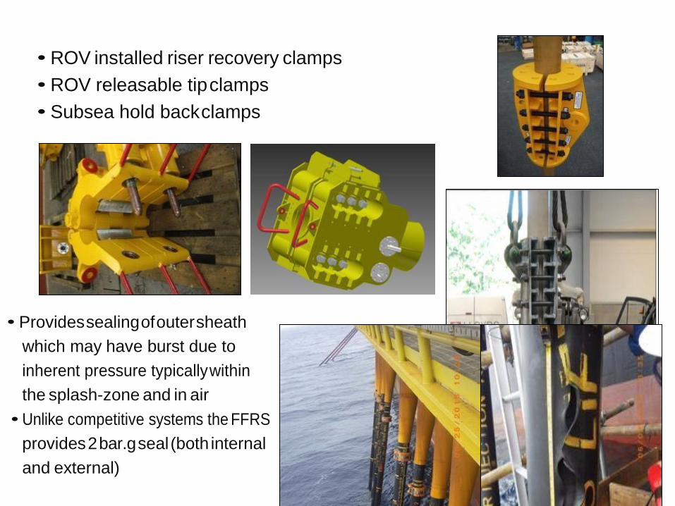
• ROV installed riser recovery clamps
• ROV releasable tip clamps
• Subsea hold back clamps
• Provides sealing of outer sheath
which may have burst due to
inherent pressure typically within
the splash-zone and in air
• Unlike competitive systems the FFRS
provides 2 bar.g seal (both internal
and external)

• Fitted with fill and vent facility
• Vent facility can be connected to
the topside manifold arrangement
• Internal gel system can be provided
to evacuate salt laden atmosphere
if required
• Spherical knuckles provide a flexible
assembly suited for dynamic
applications
• Modular design allows easy lightweight
installation around flowline
• Modular design enables length to be
varied to cover damaged location
• End clamps provide positive friction
clamp onto flowline

• Field proven gasket arrangement
successfully used on high pressure
applications on pipeline repair clamps &
swivel flanges
• Internal gel system can be provided
to evacuate salt laden atmosphere if
required
Umbilical Clamping Systems
• Used to secure umbilical’s and bundles to topside structures.
• Two piece clamp system
- lower clamp is strapped to structure using kevlar strapping system
- umbilical installed and upper clamp fitted to secure in position
• Lightweight, high strength clamps.

Distributed Buoyancy Modules
• Fitted to umbilical and flexible flowlines to reduce topside tensions and too achieve the
required installation configurations. E.g.: lazy wave.
• Two piece assembly
- inner friction clamp to provide the axial restraint in the desired position
- external buoyancy module profiled around friction clamp and strapped in place using
Roblon field proven subsea tensioning system (typically titanium straps)
• Buoyancy modules are manufactured from syntactic foam with an outer polyurethane skin
• Various densities provided dependent upon water depth


Product Overview - IMR
Pipeline Integrity Systems:
• Conceptual and feasibility studies
• Basic and front end engineering
• Methodology and risk assessment
• Detailed design and engineering including modeling and Finite Element Analysis
• Manufacture and assembly
• Factory Acceptance Testing / Pre-Qualification / Yard Trials
• QA and inspection
• In house project management from concept design to delivery
• Management of in-field installation

)
SUPERGRIP – OFFERING COMPLETE CUSTOMISED ENGINEERED SOLUTIONS
Pipeline Repair Equipment: • Emergency short term repair clamps
• Diver & diverless split sleeve pipeline repair clamps (seal only & structural retaining)
• Swivel & misalignment flanges
• Weld-less pipeline connectors (topside and subsea
• Emergency short term repair clamps
Item-1: Emergency Low Pressure Fast Track Sealing Clamps

• Developed for temporary sealing of minor
leaks on fast track applications, for projects
without contingency Emergency Pipeline
Repair Systems (EPRS)
• Enables the pipeline to be operated at a lower pressure whilst a long term pipeline repair
clamp is produced
• Installed by diver or ROV
• Typical pipeline operating pressure: 25 to 50 bar.g
• Pipeline range: 4” to 40” NS Ref: A-00203-DOC-002
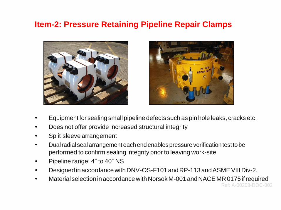
Item-2: Pressure Retaining Pipeline Repair Clamps
• Equipment for sealing small pipeline defects such as pin hole leaks, cracks etc.
• Does not offer provide increased structural integrity
• Split sleeve arrangement
• Dual radial seal arrangement each end enables pressure verification test to be
performed to confirm sealing integrity prior to leaving work-site
• Pipeline range: 4” to 40” NS
• Designed in accordance with DNV-OS-F101 and RP-113 and ASME VIII Div-2.
• Material selection in accordance with Norsok M-001 and NACE MR 0175 if required Ref: A-00203-DOC-002
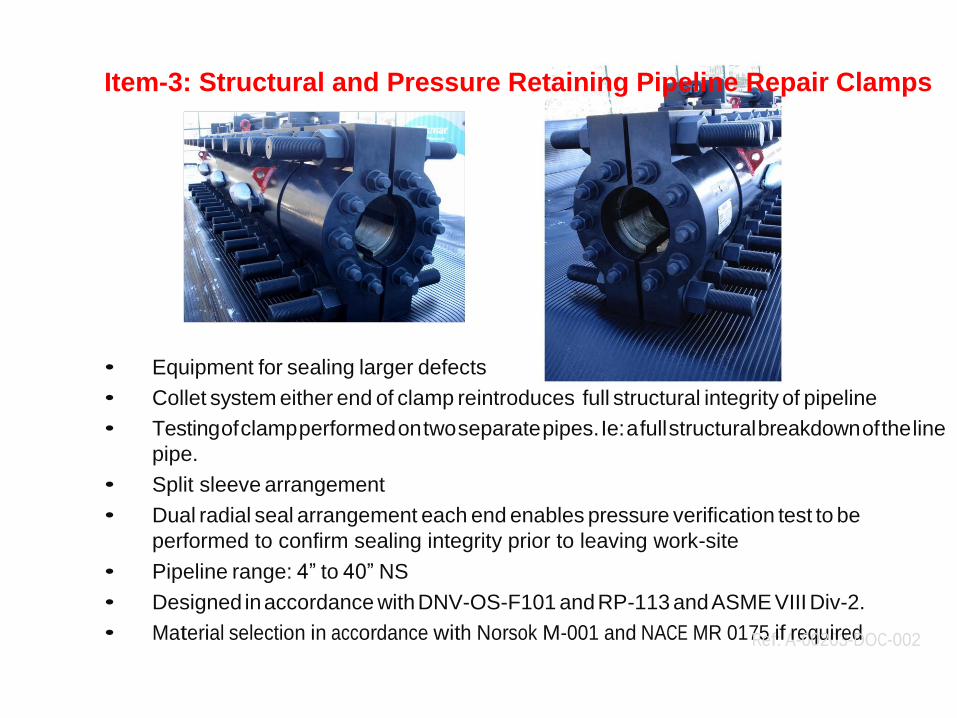
Item-3: Structural and Pressure Retaining Pipeline Repair Clamps
• Equipment for sealing larger defects
• Collet system either end of clamp reintroduces full structural integrity of pipeline
• Testing of clamp performed on two separate pipes. Ie: a full structural breakdown of the line
pipe.
• Split sleeve arrangement
• Dual radial seal arrangement each end enables pressure verification test to be
performed to confirm sealing integrity prior to leaving work-site
• Pipeline range: 4” to 40” NS
• Designed in accordance with DNV-OS-F101 and RP-113 and ASME VIII Div-2.
• Material selection in accordance with Norsok M-001 and NACE MR 017R5efi:fAr-e0q0u20ir3e-dDOC-002

Topside and Diver Installations
• Manually installed onto pipeline using certified hinged system on sizes upto and
including 14” NS. For sizes 16” NS and above a hydraulic installation toolis required
due to weight constraints affecting manual handling. The tool is also used on ROV
installations, refer to later slides
• Activation of clamps can be from either traditional subsea hydraulic tensioners or
alternatively via Supergrip (UK) supplier nut runner and torque tool. Details of which
are presented later in this presentation.
Ref: A-00203-DOC-002

ROV Installations
Hydraulic installation tool ROV control panel closes clamp performs seal verification pressure test and releases tool
• Hydraulic installation tool is required to close the clamp.
• The tool lands on the damaged pipeline and is activated by either the ROV hydraulic system,
from a downline reel from the installation vessel or subsea hydraulic power unit
• All function are performed through a hot stab / receptacle interface and ROV activated
valves.
• The tool enables controlled linear closing of the clamp ensuring all joint seals are correctly
seated prior to clamp activation
Ref: A-00203-DOC-002

ROV Interfaces
ROV Control Panel ROV hot stabs
• Hydraulic installation tool activated by either ROV hydraulic system,
downline reel or subsea hydraulic power unit
• All installation activities performed through this interface.
• Enables controlled linear

Ref: A-00203-DOC-002
Dependent upon the clients commercial strategy there are two options for activating
the pipeline repair clamps once they have been closed around the pipeline by the
installation tool:
Option-1: traditional subsea tensioners
Option-2: Supergrip supplied subsea activation tools
Considerations:
1. Subsea tensioners provide a quicker more efficient installation subsea as they are
all activated simultaneously from a suitable hydraulic power unit. However the
capital cost of the equipment is greater due to the quantity of tensioners and
hoses / fittings required.
2. The subsea activation tools are a lower cost solution when purchasing the
equipment however the time to activate the clamp subsea is slightly increased as
each individual bolt it tensioned separately.

Ref: A-00203-DOC-002
Standard subsea tensioners Standard subsea tensioners
• Nut runner is used to provide initial activation of the clamp. This provide high flow low
torque which enables the clamp seals to be partially activated in a quick manner.
• Once all bolts have been partially activated the torque tool is then applied to provide
the final high torque requirement to fully activate the clamp
• The torque tool is designed with multi-reactor points which engage with adjacent
bolts.
Ref: A-00203-DOC-002
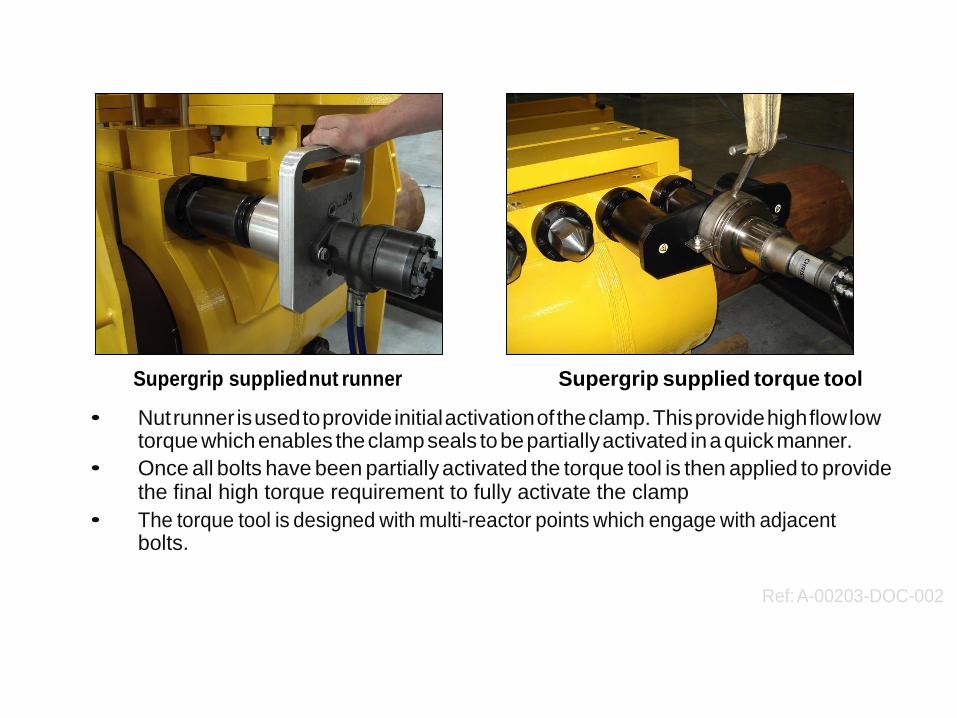
Supergrip supplied nut runner Supergrip supplied torque tool
• Nut runner is used to provide initial activation of the clamp. This provide high flow low torque which enables the clamp seals to be partially activated in a quick manner.
• Once all bolts have been partially activated the torque tool is then applied to provide the final high torque requirement to fully activate the clamp
• The torque tool is designed with multi-reactor points which engage with adjacent bolts.
Ref: A-00203-DOC-002

Pipeline Isolation Systems: • Pipeline plugs to provide 100% isolation of live pipelines to enable on-line maintenance
to be performed. Eg: valve inspection and repair, flange gasket replacement etc.
• Double block and bleed facility supplied on all plugs
• Seal verification pressure testing
• Downstream pressure monitoring during maintenance program.
• Plug pigged into position using tethered or tetherless through wall communication
• Supergrip provide fiull turn-key project from pre-isolation site survey, design and
manufacture of equipment, all project management and operating procedures to on-site
installation, monitoring and issuing of certification.

Pipeline Integrity Tools: • Bespoke pigging tools for internal pipeline inspection and maintenance
• Weld and bolted connection integrity pressure test tools
• Suitable for pressures upton ANSI-2500
• Size range: 2” to 40” NS

Bespoke Designs
ROV installed J-Tube Bellmouth

• Provides bellmouth onto subsea J-tube following flange removal
• ROV installed and hydraulically activated topside by Supergrip technicians
• Mechanical locking nuts mounted on cylinders ensure hydraulic pressure can be removed
• ROV removable after end of life service