product range awards - controlstore · product range awards: innovation + quality. 2 ... metering...
TRANSCRIPT

Valves, controls + systems
Flow, pressure andtemperature balancing
Product range
Awards:
Innovation + Quality

2
Flow, pressure andtemperature balancing
Content Page
Flow, pressure and temperature balancing
Necessity of hydronic balancing 3
Mode of operation of Oventrop valves and controls 4
Oventrop double regulating and commissioning valvesRanges of control and performance 6
Oventrop regulatorsRanges of control and performance 8
Oventrop regulating valve with integratedmetering stationRanges of control and performance 12
Oventrop metering stationsRanges of performance 13
Hydronic balancing according to aspecifying engineer’s calculation 14
Hydronic balancing on site“OV-DMPC” / “OV-DMC 2” 16
Measuring methodsDifferential pressure transmitter“OV-Connect” 17
Application in heating and cooling systems 18
Examples in chilled and radiant ceiling systems 19
Description of the products
Valves for hydronic balancing “Hycocon” 22
Double regulating and commissioning valve“Hycocon VTZ” 23
Double regulating and commissioning valve“Hydrocontrol” 24
Double regulating and commissioning valves“Hydrocontrol AFC“ “Hydrocontrol VPR”,“Hydrocontrol VTR”, “Hydrocontrol VFC”,“Hydrocontrol VFN”, “Hydrocontrol VFR” and“Hydrocontrol VGC” 25
Differential pressure regulators“Hycocon DTZ”, “Hydromat DTR” and “Hydromat DFC”26
Flow regulators“Hydromat DTR”, “Cocon QTZ” and “Cocon QFC” 27
Pressure independent control valve withautomatic flow control “Cocon QTZ” 28
Regulating valve “Cocon 2TZ” 29
Three-way valves “Tri-D TB/TR”, “Tri-D plus TB” and“Tri-M TR”Four-port valve “Tri-M plus TR”Regulating valve with reversed closing function 30
Metering stations 31
Actuators, room thermostats 32
Combination possibilities of valves and actuators 33
Working supports /Service 36

3
Necessity ofhydronic balancing
Course of pressure in a circuit
!pexcess
!ptotal!p3
!p2!p1
!p4 (appliance)
Appliance
HFDB
•m1–4•m2–4
•m3–4•m4A C E G
1 2 3 4
Why balance?Hydronic balancing of heating and coolingsystems is necessary to avoid the followingproblems:– some rooms almost never achievethe desired room temperature or arenot cooled sufficiently. This problemespecially arises in case of influenceof other heat sources
– after changing over from low temperatureto heating operation, parts of the systemare only heated after a long time
– fluctuating room temperatures especiallyarising during low demand periods
– high energy consumption although therequired room temperature regulator isinstalled
Distribution of flowThe main reason for these problems is thatincorrect flows are available in the variouscircuits. If this is the case, the problem maybe solved by installing double regulatingand commissioning valves, differentialpressure regulators or flow regulators inthe corresponding pipes. The course ofpressure in a circuit makes clear whythis occurs.
The illustration shows that the pump has toproduce a differential pressure of at least!ptotal to guarantee a sufficient supply toappliance 4. This will, however, inevitablyresult in an excessive differential pressureat the appliances 1 to 3. This too high adifferential pressure will cause anincreased flow at these appliances andthus to an increased energy consumption.To remedy this, double regulating andcommissioning valves are installed. Theexcessive differential pressure is nowabsorbed by the double regulating andcommissioning valves. The desired flowrate may be controlled and set. To be ableto control appliance 4 as well, it isrecommended to install a double regulatingand commissioning valve here, too. Thecorrect supply of each appliance is nowguaranteed.
Energy savingWrong flow rates in the various circuits leadto an increased energy consumption. Onthe one hand, a higher pump capacity mustbe provided to guarantee a sufficientsupply of each appliance and on the otherhand appliances being installed at afavorable hydronic position are thenoversupplied. This will result in an increasedroom temperature or, in cooling systems,in too low a room temperature. If theaverage temperature in a building exceedsthe nominal value by 1°C, the energyconsumption is increased by 6–10 %.
In cooling systems, temperatures being1°C too low will result in an increase inenergy consumption of about 15 %.Installations, in which the hydronicbalancing was not carried out, have to startthe heating operation earlier in order toachieve the desired temperature in time.
How to avoid noises at the TRVsIf the installation is a two pipe installation,not only the design demand but also theperiods of low demand have to beconsidered. The differential pressure at theTRVs has to be limited to approximately200 mbar. If this value is not exceeded, thethermostatic radiator valves normally donot produce any flow or whistling noises.This condition is met by installingdifferential pressure regulators in thecorresponding circuits.

4
Mode of operation of Oventrop valves and controls
5 6
1 2
3 4
Tolerance[±%]
Presetting
Valve lift [%]0 20 40 60 80 100
1.6
1.4
1.2
1.0
0.8
0.6
0.4
0.2
0
optimumcurve2
wrongcurve1
Flow
rate
• m/• mDesign
System
Double regulatingand commissioning valve !p
System!p
!pmax
!pDesign
!p
qmDesign ~ qmmax qm
Design point
without commissioningvalves
Low demand period (!p-regulated pump)
Overload period
with commissioningvalve
Low demand period (unregulated pump)
Capillary
Nominal valuesettinng !pE
Differentialpressureregulator
Isolating and orifice valve
!pmax=
!pDesign
!p
qmDesign !qmmax qm
Design point
without regulators
Low demand period
Overload period
with differentialpressure regulator
with presettableradiator valves
qmDesign ~ qmmax
(with presettableradiator valves)
Theoretical viewIn order to explain the influence of doubleregulating and commissioning valves, flowand differential pressure regulators on thehydronic conditions in the correspondingcircuits, their mode of operation in principalis illustrated on this page, only with thevalves required to this.
1 Design of double regulating andcommissioning valvesIn order to regulate flow as accurately aspossible, the correct design is veryimportant. If the presetting values are toolow, the flow tolerances will be high. Thequality of regulation falls off and the energyconsumption increases. The chart makesclear that low presetting values (< 1 for“Hydrocontrol”) will result in high tolerancesand should therefore be avoided (seeexample 1 page 14).
2 Design of flow and differentialpressure regulatorsCurve 1 shows a regulating valve beingsized incorrectly. Only 50% of the valvelift is used. Curve 2, however, shows aregulating valve which is designed the bestpossible. The desired flow is achieved atthe maximum valve lift. Stability of theregulating circuit and regulation areimproved. The valves thus have to bechosen with care. If the chosen dimensionsare too small, the flow rates are not reachedand if the chosen dimensions are too high,the results of balancing will be ineffective.
3 and 4 Double regulatingand commissioning valvesThe characteristic lines of a circuit withand without double regulating andcommissioning valve as well as the shiftingof the characteristic lines caused by theinfluence of a differential pressure regulatedpump are illlustrated here. It can be seenthat in the design the flow in the circuit isreduced by using double regulating andcommissioning valves, i.e. the flow in eachcircuit can be regulated by carrying outpresetting. If the installation is overloaded,e.g. by completely opened radiator valves,the differential pressure in the circuit is onlyincreased slightly. The supply of the othercircuits is still guaranteed (qmDesign ~ qmmax).During periods of low demand, i.e. with !pincreasing via the installation, the doubleregulating and commissioning valve onlyhas a slight effect on the characteristic lineof the circuit. Excess differential pressurecan be reduced with the help of a !pregulated pump.
5 and 6 Differential pressure regulatorsThe characteristic lines of a circuit with andwithout differential pressure regulator areillustrated here. It becomes clear that thedifferential pressure may only slightlyexceed the design value during periods oflow demand, i.e. thermostatic radiatorvalves are protected against an inadmissibleincrease of differential pressure even duringperiods of low demand, provided that thedesign value does not exceed 200 mbar.In case of overload, the differential pressureregulators only have a slight impacton the course of the characteristic line(qmDesign ≠ qmmax). When usingpresettable radiator valves, the flow inthe circuit is limited in case of overload(qmDesign ~ qmmax) (see example 2 page 14).
Supply
Return
Supply
Return

5
11 12
Return
System
Supply
“Cocon QTZ”
!p
!pmax
!pAus
!pDesign point
with “Cocon QTZ”(average nominalsetting)
Low demand period
Overload period
without regulator
with “Cocon QTZ”(high nominalsetting)
qmDesign = qmmax qm
Mode of operation of Oventrop valves and controls
7 8
9 10
Double regulating andcommissioning valve
System
Capillary
!p
!pmax=
!pDesign
!p
qmDesign ~ qmmax qm
Supply
Return
Differential pressureregulator
Low demand period
Design point
with doubleregulating andcommissioning valve
Overload period
Flow regulator
Return
System
Supply
!p
!pmax
!pDesign
!p
qmDesign = qmmax qm
Design point
without regulator
Overload period
with flow regulator
Low demand period
13 14
Flow regulator
Capillary
!p
System
Supply
Return
Differentialpressure regulator
!pmax=
!pDesign
!p
qmDesign = qmmax qm
Design point
without regulator
Overload period
with flow anddifferential pressureregulator
Low demand period
7 and 8 Combination differentialpressure regulator and double regulatingand commissioning valve for differentialpressure regulationThe characteristic line of a circuit withdifferential pressure regulator and doubleregulating and commissioning valve isillustrated here. During periods of lowdemand, the differential pressure onlyslightly exceeds the design value. By usingthe double regulating and commissioningvalve in installations without presettableradiator valves, the flow in the circuit isonly increased slightly during low demandperiods and the supply of all other circuitsis thus guaranteed (qmDesign ~ qmmax)(see example 3 page 14).
9 and 10 Flow regulatorsThe characteristic of a circuit with andwithout flow regulator are illustrated here. Incase of overload, the flow rate only slightlyexceeds the design value (qmDesign = qmmax)(see example 4 page 15).
11 and 12 Pressure independent controlvalve “Cocon QTZ”Here, the characteristic lines of a circuitwith a pressure independent control valve“Cocon QTZ” are illustrated. In case ofoverload, the flow is kept at a constant level(qmDesign = qmmax). The mode of operationis similar to that of a flow regulator but thepressure independent control valve “CoconQTZ” can additionally be equipped with anactuator or temperature controller. Not onlythe flow but also another variable (e. g. theroom temperature) can be controlled thisway.
13 and 14 Combination flow anddifferential pressure regulatorThe characteristic line of a circuit withdifferential pressure and flow regulator isillustrated here. By installing these tworegulators, the flow is limited to the designvalue in case of overload. During periodsof low demand, the differential pressure islimited to the design value, too (qmDesign =qmmax, !pDesign = !pmax).The ciruit is hydronically balanced at anypoint of operation. The supply of the circuitsis always guaranteed (see example 6page 15).

6
Oventrop double regulating and commissioning valvesRanges of control and performance
Flow balancing via double regulating and commissioning valvesRegulation according to pipework calculation or by using a !p measuring gauge
“Hycocon ATZ/VTZ/ETZ/HTZ” “Hydrocontrol VTR/ATR”/“Hydrocontrol MTR”/“Aquastrom C”
Flow ranges between lowest and highest presetting with !p= 0.1bar via the double regulating and commissioning valve.The below examples only show the valves which are really required for hydronic balancing.
“Hycocon ETZ”: “Aquastrom C”:
“Hydrocontrol MTR”:
Example: Two pipe heating system for low to medium flow rates. Example: Two pipe heating system for medium to high flow rates.
00
22
44
66
00
22
44
66
Conversion of the flow and differential pressure values from adesign calculation on the flow rates with !p=0.1 bar illustrated here:
Design calculation: !pA, V·A
Conversion: V·0.1 bar = V·A ·"!0.1bar
!pA
Flowrange!p=0.1 bar
Flow
rateqm[kg/h]
Flowrange!p=0.1 bar
Flow
rateqm[kg/h]

7
“Hydrocontrol VFC” “Hydrocontrol VFC/VFR/VFN/VGC”
Flow ranges between lowest and highest value of presetting with !p=0.1bar via the double regulating and commissioning valve.The below examples only show the valves which are really required for hydronic balancing.
Oventrop double regulating and commissioning valvesRanges of control and performance
Example: Central heating system with flanged connections.
0
OV
08
4
0 8
4
0
OV
0
OV
Example: Cooling system with flanged connections.
Chiller
Chiller
Chiller
Example:!pA = 0.15 bar, V·A = 850 kg/h
V·0.1 bar = V·A · = 694 kg/h"!#0.1bar
0.15 bar
With the help of the value V·0.1bar a preselection, e.g. “Hydrocontrol VTR”, DN 20,can be made (see broken line).
Flowrange!p=0.1 bar
Flow
rateqm[kg/h]
Flowrange!p=0.1 bar
Flow
rateqm[kg/h]

8
The below examples only show the valves which are really required for differential pressure regulation.
Oventrop regulatorsRanges of control and performance
Example: Differential pressure regulation in installationswith presettable thermostatic radiator valves(circuits with low to medium flow rate).
Example: Differential pressure regulation in installationswith presettable thermostatic radiator valves(circuits with medium to high flow rate).
Differential pressure regulation Differential pressure regulation
“Hycocon DTZ” (50–300 mbar) “Hycocon DTZ” (250–600 mbar) “Hydromat DTR” (50–300 mbar) “Hydromat DTR” (250–700 mbar)
Flow ranges of the differential pressure regulator “Hydromat DTR”for adjustable differential pressures in the circuits 50–300 mbar or250–700 mbar
Flow ranges of the differential pressure regulator “Hycocon DTZ”for adjustable differential pressures in the circuits 50–300 mbar or250–600 mbar
Flowrange
Flow
rateqm[kg/h]
Flowrange
Flow
rateqm[kg/h]

9
Example: Differential pressure regulation with flow limitationin installations with non presettable thermostaticradiator valves.
Differential pressure regulation Differential pressure regulation with flow limitation
Example: Differential pressure regulation in installations withflanged connections.
“Hycocon DTZ” (50–300 mbar)/“Hycocon VTZ”“Hycocon DTZ” (250–600 mbar)/“Hycocon VTZ”
“Hydromat DFC” (200–1000 mbar)“Hydromat DFC” (400–1800 mbar)
Flow ranges of the differential pressure regulator “Hydromat DFC”for adjustable differential pressures in the circuits 200–1000 mbaror 400–1800 mbar
Flow ranges of the differential pressure regulator “Hycocon DTZ”for adjustable differential pressures in the circuits 50–300 mbar or250–600 mbar and additional flow limitation at the double regulatingand commissioning valve “Hycocon VTZ”
Oventrop regulatorsRanges of control and performance
Flowrange
Flow
rateqm[kg/h]
Flowrange
Flow
rateqm[kg/h]

10
The below examples only show the valves which are really required for regulation.
Oventrop regulatorsRanges of control and performance
Example: Differential pressure regulation with flow limitationin installations with non presettable thermostaticradiator valves.
Example: Flow regulation e. g. in cooling systems. Presetting canbe set at regulator and is visible from the outside.
Differential pressure regulation with flow limitation Flow regulation
“Hydromat DTR”/“Hydrocontrol VTR”“Hydromat DTR”/“Hydrocontrol VFC”
“Hydromat QTR”
Adjustable flow values at “Hydromat QTR”.Flow regulation for an application range between 40 kg/h and 4000 kg/h
Flow ranges of the differential pressure regulator “Hydromat DTR” for adjustabledifferential pressures in the circuits 50–300 mbar or 250–700 mbar. For the“Hydromat DFC” differential pressures of 200–1000 mbar or 400–1800 mbar arepossible. The additional flow limitation is carried out at the double regulating andcommissioning valve “Hydrocontrol VTR/VFR”.
Adjustableflow
range
Flow
rateqm[kg/h]
Adjustableflow
range
Flow
rateqm[kg/h]

11
Flow regulation Flow regulation
“Cocon QTZ/QFC” with actuators“Hycocon DTZ”/“Hycocon VTZ”
Adjustable flow values for regulation with combination:Set differential pressure at “Hycocon DTZ” between 50 and 600 mbar(pressure is taken at “Hycocon VTZ”). With the help of the pressure losschart (see data sheet “Hycocon VTZ, design as example 5, page 15)determine the presetting value for “Hycocon VTZ” for the required flowrate and set at the handwheel.
Adjustable flow rates at “Cocon QTZ”/QTR/QFC”:Flow regulation for an application range between 30 kg/h–120.000 kg/h.The “Cocon QTR/QFC” allow the setting of smaller flow rates up tocomplete isolation.
Example: Flow regulation with the help of the combinationdifferential pressure regulator “Hycocon DTZ” and doubleregulating and commissioning valve “Hycocon VTZ”.
Example: Flow regulation at the pressure independent control valve“Cocon QTZ”.
Installation alsopossible in thesupply pipe
Installation alsopossible in thesupply pipe
Oventrop regulatorsRanges of control and performance
Adjustableflow
rangeFlow
rateqm[kg/h]
Flowrange
Flow
rateqm[kg/h]

12
Oventrop regulating valve with integrated metering stationRanges of control and performance
Flow and temperature balancing by use of regulating valvesRegulation according to pipework calculation or by using a !p measuring gauge
Regulating valve “Cocon 2TZ” with integrated metering station
Example: Installation with chilled ceiling system to reducethe room temperature.
Conversion of the flow and differential pressure values from adesign calculation on the flow rates with !p=0.1 bar illustrated here.
Flowrange!p=0.1 bar
Flow
rateqm[kg/h]

13
Oventrop metering stationsRanges of performance
Flow balancing by use of metering stationsRegulation according to pipework calculation or by using a !p measuring gauge
Metering station DN 65 – DN 1000Flow values with !p = 1 bar via the metering station
Metering station DN 15 – DN 50Flow values with !p = 1 bar via the metering station
08
6
4
2
0
8
6
4
2
0
Brass resistant to dezincification
Cast iron Stainless steel
Example: Central heating system with female threaded connections. Example: Central heating system with flanged connections.
Example: !pA = 0.15 bar, V·A = 850 kg/h
V·0.1 bar = V·A · = 694 kg/h"!#0.1bar
0.15 bar
With the help of the value V·0.1 bar a preselection, e.g. “Cocon 2TZ”, DN 20,can be made (see broken line).

2400
3
4
2
3
4
5
6
78910
2
3
4
5
6
78910
10
2
3
4
5
6
78910
2
3
4
5
6
789103 5
2 2 23 3 34 4 45 5 56 6 67 7 78 8 810 10 104 5310
2
0.25 0.5 1 2 3 4 5 8
10 2
6 10
150
14
Hydronic balancing according toa specifying engineer’s calculation*
* The illustrated examples only take those valves into consideration which are required for balancing.
Double regulating and commissioningvalve
Differential pressure regulator Differential pressure regulator and flowlimitation with double regulating andcommissioning valve
Return
Supply
Example 1:
Required:Presetting “Hydrocontrol VTR”
Given:Flow rate circuit qm = 2000 kg/hDifferential pressure valve
!pV = 100 mbarValve size DN 25
Solution:Presetting 5.0(taken from chart 1060108)
Example 2:
Required:Size “Hydromat DFC”
Given:Flow rate circuit qm = 30000 kg/hDifferential pressure system
!p = 800 mbar(corresponds to the nominal value settingat the “Hydromat DFC”)
Solution:Size “Hydromat DFC” DN 65.30000 kg/h is smaller than the maxpermissible flow rate qmmax.
Note:Differential pressure system = pressureloss radiator valves and lockshieldvalves + pressure loss radiator + pressureloss pipework
Return
Supply
!p
!pV
Example 3:
Required:Presetting double regulating andcommissioning valve
Given:Differential pressure system!pA= 50 mbarFlow rate circuit qm= 2400 kg/h
Differential pressure system(at “Hydromat DTZ”)!pE = !p = 200 mbarSize of pipe DN 32
Solution:Presetting 3.0(taken from chart 1060110)
Differential pressure of double regulatingand commissioning valve!pV = !p–!pA
= 200 –50 mbar!pV = 150 mbar
Bronze double regulating andcommissioning valve 1060110
Pressureloss
!p[mbar]
Pressureloss
!p[Pascal]
Flow rate qm [kg/h]
Presetting
Bronze double regulating andcommissioning valve 1060108
10
7543210.50.25
2
102 43 101010 888 777 666 555 444 333 222
3 10987
6
5
4
3
2
10987
6
5
4
3
2
10
10987
6
5
4
3
2
10987
6
5
4
3
2
4
3
2000
Pressureloss
!p[mbar]
Pressureloss
!p[Pascal]
Flow rate qm [kg/h]
Presetting
System
Double regulating andcommissioning valve Sy
stem
Differentialpressureregulator
Return
System
Capillary
Supply
!p
!pV
!pA
Differential pressureregulator
Double regulating andcommissioning valve
Nominal value setting !pE
Differential pressure regulator 1064651
Mass flow qm [kg/h]
Nominalvalue
!pE=[mbar]
Nomninalvalue
!pE=[kPa]

15
Supply
Return
“Cocon QTZ”
!p
System
Hydronic balancing according toa specifying engineer’s calculation*
* The illustrated examples only take those valves into consideration which are required for balancing.
Flow regulator Regulating valve “Cocon QTZ” Combination of flow and differentialpressure regulator for flow anddifferential pressure regulation
Flow regulator
Return
System
Supply
!p
!pQ
!pO
Flow regulator
Return
System
Capillary
Supply
!p
Example 4:
Required:Size “Hydromat QTR” + differential pressureof regulator !pQ
Given:Flow rate circuit qm = 1000 kg/hExisting differentialpressure of circuit !pO = 300 mbarDifferential pressureof system p = 100 mbar
Solution:Size “Hydromat QTR” DN 20(taken from pressure loss chartsDN 15 – DN 40)
According to the charts, the minimumregulator size is chosen for qm = 1000 kg/h.
The flow regulator has to be set to1000 kg/h.
Differential pressure of regulator!pQ= !pO–!p
= 300–100 mbar!pQ = 200 mbar
200
1200
1000
800
600
400
200
500 1000 1500 2000
Flow
rateqm
[kg/h]
Differential pressure [mbar]
Note:The excessive differential pressurewhich has to be produced by the regulator,amounts to !pQ = 200 mbar.This is the minimum !p requiredto ensure accuracy.
Example 5:
Required:Size and flow range
Given:Flow rate circuit qm = 600 kg/h
Solution:“Cocon QTZ”, DN 15,150 up to 1050 l/h
The regulating valve “Cocon QTZ” has tobe set to 600 kg/h.
Example 6:
The differential pressure and theflow regulator are designed accordingto examples 2 and 4.
Differential pressureregulator
Volume flow characteristic line for differentpresettings
Differential pressure p1 - p3 [bar]
Volumeflow[l/h]

16
==================
=Ventil-Setup
Oventrop
Typ: Hydrocon
Größe: 020
0
64
20
64
20
1
7
43
6
98
5
2
0
“OV-DMPC”
“OV-DMC 2”
Regulation at double regulating andcommissioning valve “Hydrocontrol VTR”
Regulation at double regulating andcommissioning valve “Hycocon VTZ”
Hydronic balancing on site“OV-DMPC”“OV-DMC 2”
Even a subsequent hydronic balance or acorrection at the heating or cooling systemleads to an increased economical profitand comfort. For this purpose, Oventropoffers the differential pressure measuringneedles for the measuring techniques“classic” and “eco”.The new measuring system “OV-DMPC” isespecially designed for an easy regulationon site. The measuring system is equippedwith an USB interface for the connection tostandard notebooks. Together with theincluded Windows software, it enables aneasy regulation of heating and coolingsystems. The “OV-DMPC” is used fordifferential pressure measurement atregulating valves and the resultingdetermination of the flow rate. Calculationof the presetting for double regulating andcommissioning valves is possible afterhaving entered the valve data and therequired nominal flow rate. Thecharacteristic lines of all Oventropregulating valves are stored in the software.All accessories (e. g. operating keys,measuring adapters etc.) required for flowmeasurement are included in the servicecase.The measuring system “OV-DMC 2” isespecially designed for the flowmeasurement of Oventrop regulatingvalves. It features a water- and dustproofkeyboard and is equipped with an offlinerechargeable set of batteries. Allaccessories (e. g. operating keys,measuring adapters etc.) required for flowmeasurement are included in the servicecase. The characteristic lines of allOventrop regulating valves are stored in theflowmeter. The flow rate is indicated afterhaving entered the valve size and thepresetting. To ease handling, zero balanceis carried out automatically. If the presettingvalue of the double regulating andcommissioning valve has not beencalculated, this can be done by the“OV-DMC 2”. After having entered thevalve size and the required flow rate, the“OV-DMC 2” calculates the differentialpressure, compares the nominal and actualvalues and the required presetting will bedisplayed.
Measuring technique “classic”
Measuring technique “eco”

17
Measuring methodsDifferential pressure transmitter “OV-Connect”
“OV-Connect”
OV-Balance method:The main advantage of this method is thatthe values of presetting for the doubleregulating and commissioning valves maybe calculated on site with the help of theOventrop flow-meter “OV-DMC 2” and thatthe complete system may be regulated byonly one person. The time required for thehydronic balance is reduced considerablyprovided that the installation is structuredclearly.Before carrying out the regulation, allisolating valves within the circuit of appliancehave to be opened. Moreover, the installationhas to correspond to the design rate, e.g.thermostatic valves preset and thermostatsremoved.The sequence of regulation is detailed in theoperating instructions of the “OV-DMC 2”(11 steps).
Differential pressure transmitter“OV-Connect”The Oventrop differential pressure transmitter“OV-Connect” is designed to obtain apermanent differential pressure measurementacross Oventrop valves with measuringtechnique “classic” in heating, cooling andpotable water systems which are operatedwith water or water glycol mixtures. Thereceived signals can be processed by anelectronic control and monitoring unit.The differential pressure of the valve ismeasured via the measuring needles andthe 6 mm copper pipes at the pressure testpoints.Under working conditions, the appliancepasses on an output signal proportional tothe measured differential pressure (0 – 10 V).
V16
V17
V18V15
V14
V13V10
V11
V12
V7
V8
V9
V4
V5
V6
V1
G1 G2 G3 G4 G5 G6
V2
V3
Regulating groups 1–6
Double regulating and commissioningvalve in pump circuit
Group valves
Example: OV-Balance method
Ausgangssignal
Spa
nnun
gU
[V]
Differenzdruck p [kPa]
1008060402000
10
8
6
4
2
!
P1
P2
24
6
0
24
6
0
Leit- und
Überwachungseinheit
Application example:
Control andmonitoring unit
Output signal
TensionU[V]
Differential pressure !p [kPa]

18
Application inheating and cooling systems
Example:Scheme of an air heating installation in which the flow rate is almost constant.Preset double regulating and commissioning valves provide a static hydronic balancing.
Example:Scheme of a two pipe heating system which has to be regulated to a pre-calculated designpoint by use of double regulating and commissioning valves.Regulation:Via a directly presettable double regulating and commissioning valve.
In principle, correctly sized chilled orheating surfaces, pipes, double regulatingand commissioning valves and pumpsguarantee an optimum hydronic balance ofheating and cooling systems. To minimisedeviations of the differential pressure fromthe design state, the use of regulatingvalves and regulated pumps may berecommendable.During planning new heating or coolingsystems, heat demand and pipeworkcalculations are used taking the demandsof the new decree for energy saving intoconsideration, including the control andperformance ranges of the valves forhydronic balance as well as the lossescaused by the resistance of pipes.
To calculate the hydronic of the pipework:1. the heat demand or the cooling load aredetermined first,
2. the heating and chilled surfaces as wellas their flow rates are calculated with thegiven temperature differences beingtaken into consideration,
3. the sizing of the pipework for the flowrates which are to be circulated is carriedout. Here, the differential pressurebetween the circuits, e.g. in heatingsystems, should be between 100 and200 mbar,
4. the double regulating and commissioningvalves, differential pressure and flowregulators are selected and their valuesof presetting are determined,
5. the value of presetting (if assigned) isalso determined for each appliance,
6. the pump head of the pump isdetermined.
During the installation phase which is nowfollowing, the system is already balanced ifthe valves for hydronic balance are installedwith their values of presetting calculatedbefore. An additional balance is notrequired.Examples of application of the proceduresdescribed above are illustrated opposite.

19
Examples inchilled and radiant ceiling systems
System illustration:Scheme of a cooling system in which theflow rate towards the chillers shall remainconstant and independent of the demandswithin the other sections of the system(limitation of the flow rates).For such installations, the distribution ofthe flow rate for the circuits results fromcalculation programs. The values maybe set directly at the flow regulators.In case of varying demand, the automaticflow regulator guarantees an automaticadaptation of the flow rate to the set valuewithin the circuits.
System illustration:Scheme of a two pipe heating systems withnon-presettable thermostatic valves orradiator lockshield valves in which the flowrate is distributed up to a higher constantvalue depending on the heat demand butin which the differential pressure within acircuit shall not exceed a given maximumvalue.This combination of volume and differentialpressure limitation is rendered possible bythe installation of a double regulating andcommissioning valve in the supply pipe anda differential pressure regulator in the returnpipe.Here, the values of presetting for the doubleregulating and commissioning valve andthe differential pressure regulator for theoptimum design point also result from theplanning stage and the hydronic balance isestablished automatically.The differential pressure regulator incombination with the double regulatingand commissioning valve then takes overthe limitation with the flow rate rising(thermostatic valves open) and thedifferential pressure rising (thermostaticvalves close).
System illustration:Scheme of a two pipe heating system inwhich the flow rate is distributed dependingon the demand but in which the differentialpressure shall not exceed maximum values(limitation of differential pressure).The values of presetting for presettablethermostatic valves resulting from thepipework calculation represent the optimumflow rate distribution in the design state.A sufficient supply is guaranteed.The additional application of a differentialpressure regulator is useful if the demandis varying, e.g. if a major part of theappliances is closed and the differentialpressure of an appliance increasesconsiderably (e.g. more than 200 mbar).The value of presetting for the differentialpressure regulator may also be calculatedduring the planning stage.The differential pressure regulatorsguarantee a permanent control of thedifferential pressure to the value ofpresetting within the circuits.

t
20
Examples inchilled and radiant ceiling systems
2
1
Room thermostatwith change-over
Central change-over command
Cooling/heating
Cooling
Roomthermostat
1 Two pipe cooling systemThe simplest method to reduce the roomtemperature by using a chilled ceilingsystem is illustrated by the two pipe system.For this purpose, Oventrop offers thefollowing products:– the presettable pressure independentcontrol valve “Cocon QTZ” is installed inthe return pipe of the chilled ceiling forthe regulation of the chilled water flow
– an electric actuator receiving controlcommands from a room thermostat ismounted on the valve
– a ball valve is installed in the supply pipeof the chilled ceiling to shut off the chilledwater flow. A dew point control whichshuts off the flow of chilled water in caseof condensation is installed in the supplypipe
2 Two pipe cooling/heating systemIf a two pipe system is also used forheating, the following products could beused:– valve “Cocon 2TZ” with electric actuator– dew point control– double regulating and commissioning valve– differential pressure regulatorHere, a central changeover of the supplyand return pipe from cooling to heatingoperation takes place and vice versa.During cooling operation, the valve“Cocon 2TZ” is opened via a roomthermostat in case of rising roomtemperature.During heating operation, the “Cocon 2TZ”valve is closed via a room thermostat withthe room temperature rising.
Cooling
Room

21
2
1
tt
Cooling
Heating
Cooling
Heating
Room thermostat, LON®
Roomthermostat
Examples inchilled and radiant ceiling systems
1 Three pipe cooling/heating systemA three pipe system is used if the fluid forcooling operation and the fluid for heatingoperation are transported in separatesupply pipes and if they are fed back to thecooler or the heat source in a common pipe.During cooling operation, the actuator“Uni EIB” which is controlled by the EIBsystem, ensures, with the valve of the“Series P”, the supply to the chilled orradiant ceiling element. Moreover, the binaryentry of the actuator “Uni EIB” allows theconnection of a dew point control deviceand/or a window contact. The supply of theheating fluid is controlled the same way.The mass flow is regulated by use of thecommon radiator lockshield valve “Combi 3”also allowing filling and draining.
2 Four pipe heating/cooling systemA four pipe system is used if the commonconnections to the chilled or radiant ceilingare served by separate heating and coolingsupply and return pipes. The chilled andheating water flows are adjusted by thepressure independent control valves“Cocon QTZ”, complete with electrothermalactuators, which are mounted on the returnpipe. An activated isolation valve,comprising of a “Series AZ” high kv valveand electrothermal actuator is mounted oneach supply pipe, will be closed incombination with the appropriate returnvalve when the chilled radiant panelswitches between heating and coolingmodes. To avoid condensation, the dewpoint control closes the chilled water returnvalve via the actuator.

22
Valves for hydronic balancing “Hycocon”
1
2 3
4
The Oventrop series “Hycocon” made ofDZR brass comprises small, compact valvesfor use in heating, cooling and airconditioning systems PN 16 between –10 ºCand +120 ºC.The series “Hycocon” consists of thefollowing components:“Hycocon VTZ”: Double regulating and
commissioning valve“Hycocon ATZ”: Isolating and orifice valve“Hycocon ETZ”: Regulating valve with AV6
insert for thermostats oractuators
“Hycocon HTZ”: Regulating valve withspecial insert for high flowrates and for thermostatsand actuators
“Hycocon DTZ”: Differential pressureregulator
Connection thread M 30x1.5The sizes DN15, DN 20, DN 25, DN 32 andDN 40 are available and the valves may besupplied with female or male threadedconnection. Installation is possible in thesupply and the return pipe.The valves “Hycocon VTZ” and “HycoconATZ” are supplied with insulation shell(suitable up to 80 ºC). The new valve insertof the “Hycocon” valves allows thereplacement of the handwheels or thebonnets for isolation, regulation anddifferential pressure regulation withoutdraining the system (DN15, DN 20, DN 25with the help of the “Demo-Bloc”).Combined with a thermostat, temperaturecontroller or electrothermal or electromotiveactuator, the “Hycocon ETZ/HTZ” valvesmay be used as a dynamic regulating valve.When fitted with an electromotive actuatorEIB or LON®, it may even be used as anintelligent regulating valve.With these universal connection possibilities,Oventrop offers a practical and effectivesolution for any automatic and manualhydronic balancing in the Building ServicesIndustry.
1 “Hycocon HTZ” with bonnets– double regulating and commissioningvalve
– differential pressure regulator– isolating and orifice valve2 “Hycocon HTZ” with thermostat,electrothermal or electromotive actuator3 System illustrationIsolating and orifice valve “Hycocon ATZ”and double regulating and commissioningvalve “Hycocon VTZ” in a heating riser4 “Hycocon VPZ” and “Hycocon APZ”both ports with press connection.For the direct connection of copper pipesaccording to EN 1057 or stainless steelpipes.

23
Double regulating and commissioning valve “Hycocon VTZ”
1
2
4
3
Oventrop double regulating andcommissioning valves “Hycocon VTZ” areinstalled in hot water central heating andcooling systems and serve to achieve ahydronic balance between the variouscircuits of the system.Precise balancing can be achieved dueto an infinitely adjustable presetting withmemory position which is lockable andlead sealable. Sizes DN 15 to DN 25 withsix and sizes DN 32 and DN 40 even witheight major graduation values divided intosteps of 1/10th (i.e. 60 or 80 presetting values)guarantee a high resolution with small flowtolerances.Installation is possible in either the supplyor the return pipe.
Advantages:– supplied with insulation shell (suitable upto 80 °C)
– the location of all functioning componentson one level allows a simple assembly andeasy operation
– only one valve for 5 functions:presettingmeasuringisolatingfillingdraining
– supplied with mounted pressure test pointand drain valve (measuring technique“eco”)
– easy filling and draining by fitting aseparate tool (accessory) to one of thepressure test points
– infinitely adjustable presetting, exactmeasurement of pressure loss and flowwith the help of the pressure test points
– thread according to EN 10226 (BS 21)suitable for Oventrop compressionfittings (one edge olive) for copper pipeswith a max. diameter of 22 mm as wellas Oventrop composition pipe “Copipe”14 and 16 mm
Models available: both ports female ormale thread.Dimensions and flow capacities:DN 15 kvs = 1.7DN 20 kvs = 2.7DN 25 kvs = 3.6DN 32 kvs = 6.8DN 40 kvs = 10.0
1 Double regulating and commissioningvalve “Hycocon VTZ”Model: both ports female thread accordingto EN 10226 (BS 21)Awards:
ISH Frankfurt“Design Plus”
Design Award Switzerland
International ForumDesign HanoveriF design award
Nominated for theDesign Award of theFederal Republic of Germany
2 Double regulating and commissioningvalve “Hycocon VTZ” combined withflow-meter “OV-DMC 2”
3 PresettingBasic and fine setting scale
4 Pressure test points for usewith flow-meter “OV-DMC 2”

•
•
••
•
•
•
•
24
Double regulating and commissioning valve “Hydrocontrol”
1
2
•
•
•
••
•
•
•
1
2
•
•
••
•
•
•
•
•
•
•
••
•
•
•
pressure test pointsand fill-and-drain ballvalve with O-ring seal(measuring technic “classic”)
* DZR = dezincification resistant brass
direct reading of the presetting
bronze body (Rg 5)
maintenance-free due todouble O-ring seal
stem and valve discmade of brass (DZR*)
patented measuringarrangement
thread accordingto EN and BS 21
pressure test points withO-ring seal (measuringtechnic “classic”)
flanges accordingto DIN and BS 4504
* DZR = dezincification resistant brass
direct reading of the presetting
cast iron body(EN–GJL–250)
maintenance-free due todouble O-ring seal
stem made of brass (DZR*)valve disc made of bronze (Rg 5)
patented measuringarrangement
With their balancing systems, Oventrop offersthe installer all the valves and valvecombinations necessary to achieve thehydronic balance of heating and coolingsystems. The products can be deliveredseparately or as a system. Thus theappropriate valves and valve combinationsare available for any possible demand.The bronze double regulating andcommissioning valves “Hydrocontrol VTR”/“Hydrocontrol VFC” are installed in hot watercentral heating systems (“Hydro-control VTR”: PN 25/150 °C, with pressconnection: max. 120 °C,“Hydrocontrol VFC”: PN 16/150°C) andcooling systems in order to provide ahydronic balance between the variouscircuits of the system. The bronze doubleregulating and commissioning valves“Hydrocontrol VFR” are also suitable for coldsalt water (38 °C max.) and domestic water.The calculated flow rate or pressure loss canbe preset for each individual circuit, thusmaking the hydronic balance easy to achieve.They can be installed in either the supply orthe return pipe.Advantages:– the location of functioning components onone level allows a simple assembly andeasy operation
– only one valve for 5 functions:• presetting• measuring• isolating• filling• draining
– low pressure loss (oblique pattern)– infinitely adjustable presetting, exactmeasurement of pressure loss and flow byusing the pressure test points(measuring technique “classic”)
– thread of “Hydrocontrol VTR” according toEN 10226 (BS 21), suitable forOventrop compression fittings (one edgeolive) for copper pipes with a max.diameter of 22 mm
– flanges of “Hydrocontrol VFN”,“Hydrocontrol VFR” and “HydrocontrolFR”: round flanges according toDIN EN 1092-2 (BS 4504), lenghtsaccording to DIN EN 558-1 (BS 7350),basic series 1
– groove connections for couplings of“Hydrocontrol VGC” suitable for couplingsof the systems Victaulic and Grinnell
– fill and drain ball valve with internal stopand pressure test point with O-ring sealbetween valve body and test point(no additional seals required)
– patented measuring channel led aroundthe stem assembly to the test pointsensures the best possible accuracybetween the differential pressuremeasured at the pressure test points andthe actual differential pressure of the valve.
1 Sectioned double regulating andcommissioning valve “Hydrocontrol VTR”Awards:
International Design AwardBaden-Württemberg
Good Design Award Japan
International Forum Design HanoverAward iF
2 Sectioned double regulating andcommissioning valve “Hydrocontrol VFC”Award:
Pragotherm PragueDiploma for the best exhibit

25
6
7
3
1 2
4
5
Double regulating and commissioning valves“Hydrocontrol AFC”, “Hydrocontrol VPR”, “Hydrocontrol VTR”
“Hydrocontrol VFC”, “Hydrocontrol VFN”,“Hydrocontrol VFR”, “Hydrocontrol VGC”
8
1 Double regulating and commissioningvalve “Hydrocontrol VTR”both ports female thread according toEN 10226 and BS 21, sizes DN 10 – DN 65both ports male thread with collar nuts,sizes DN 10 – DN 50 or both portspress connection, sizes DN 15 – DN 50.Complies with BS 7350 and BS 5154.Body and bonnet made of bronze Rg5,valve disc with PTFE seal, stem and valvedisc made of dezincification resistant brass.DVGW, SVGW and WRAS approval forDN 15 – DN 32.The valves “Hydrocontrol VTR” in thesupply respectively return pipe can beclearly marked by use of the replaceablecolour rings.2 Possible connections for the model“Hydrocontrol VTR” with both ports malethread:– weldable tailpipes– solder tailpipes– male screwed tailpipes– female screwed tailpipes– connection piece for all pipes3 Double regulating and commissioningvalve “Hydrocontrol VPR” both ports withpress connection. For the direct connectionof copper pipes according to EN 1057 orstainless steel pipes.4 Double regulating and commissioningvalve “Hydrocontrol VFC” PN 16both ports flanged, sizes DN 20 – DN 400.Body made of cast iron EN-GJL-250 DINEN 1561, valve disc with PTFE seal, bronzebonnet (D 200-DN 400 made of nodularcast iron), stem and valve disc made ofdezincification resistant brass, sizes DN 65and above bronze valve disc.Round flanges according to DIN EN 1092-2Lengths according to DIN EN 558-1, basicseries 1 and BS 7350Also available with hole circle according toANSI-Class 1505 Double regulating and commissioningvalves “Hydrocontrol VFR”-PN 16/“Hydrocontrol VFN” – PN 25– Double regulating and commissioningvalve “Hydrocontrol VFR” – PN 16both ports flanged, sized DN 50 – DN 200.Body, bonnet and disc made of bronze,stem made of stainless steel. Dimensionsof flanges identical with “HydrocontrolVFC”.Round flanges according to DIN EN1092-2Lengths according to DIN EN 558-1basic series 1 and BS 4504
– Double regulating and commissioningvalve “Hydrocontrol VFN” – PN 25both ports flanged, sized DN 65 – DN 300.Body made of nodular cast ironEN-GJS-500.Round flanges according to DIN EN1092-2Lengths according to DIN EN 558-1basic series 1 and BS 4504
6 “Hydrocontrol AFC”Sizes DN 65 – DN 1507 Double regulating and commissioningvalve “Hydrocontrol VGC”both ports groove connection for couplings,DN 65 – DN 300.Suitable for couplings of the systemsVictaulic and Grinell.Body made of cast iron EN-GJL-250 DINEN 1561, disc with PTFE seal, bonnet(DN 200 – DN 300 made of nodular castiron) and valve disc made of bronze, stemmade of brass resistant to dezincification.8 Valves for supply and return pipeThe valve for the return pipe has the samefunctions as the double regulating andcommissioning valve “Hydrocontrol VTR”except for the presetting.
In the flow pipeDouble regulatingand commissioningvalve with presetting
In the return pipeIsolating and orificevalve withoutpresetting

26
Differential pressure regulators“Hycocon DTZ”, “Hydromat DTR”, “Hydromat DFC”
1
2
1 Differential pressure regulator“Hycocon DTZ”The differential pressure regulator is aproportional regulator working without auxiliaryenergy. It is designed for use in heating andcooling systems to maintain a constantdifferential pressure within a necessaryproportional band.The nominal value isinfinitely adjustable between 50 mbar and300 mbar or 250 mbar and 600 mbar. PN16, 120 °C– high flow capacity– nominal value can be locked– very good optical display of the nominalvalue at any time
– installation in the return pipe– with isolating facility– supplied with drain valve– easy filling and draining by screwingseparate tool (accessory) onto one ofthe pressure test points (possibility toconnect a flexible hose)
– pressure balanced valve disc– all functioning components on one level– thread according to EN 10226 (BS 21)suitable for Oventrop compression fittings(one edge olive) for copper pipes with amax. diameter of 22 mm as well asOventrop composition pipe “Copipe”14 and 16 mm
– female and male thread
2 Differential pressure regulator“Hydromat DTR”The differential pressure regulator is aproportional regulator working withoutauxiliary energy. It is installed in heatingand cooling systems of existing and newbuildings for a decentral or central regulationof the differential pressure.The regulators maintain a constant differentialpressure within a necessary proportional band.The sizes DN 15 to DN 50 are infinitelyadjustable between 50 mbar and 300 mbarand size DN 50 additionally between250 mbar and 700 mbar.The “Hydromat DFC” sized DN 65 to DN 100is infinitely adjustable between 200 mbar and1000 mbar or 400 mbar and 1800 mbar.Additional technical information:PN 16, –10 °C up to 120 °CConnections DN 15 to DN 50:– both ports female thread according to EN/BS– both ports male thread with collar nutConnections DN 65 to DN 150:– both ports flanged according toDIN EN 1092-2, PN 16 (corresponds toISO 7005-2, PN 16)Lengths according to DIN EN 558-1, basicseries 1 (corresponds to ISO 5752 series 1)
Advantages:– high flow capacity– nominal value can be locked– very good optical display of nominal valueat any time
– installation in the return pipe (DN 15 to DN 50)– with isolating facility– with ball valve for filling and draining– pressure balanced valve disc– existing double regulating andcommis-sioning valves can be convertedto differ-ential pressure regulators(identical bodies)
– all functioning components on one levelThis item is protected by patent.Awards:
Industrial Forum Design HanoverAward iFPragotherm, Prague, Grand Prix
27
1
Flow regulators“Hydromat QTC”, “Cocon QTZ”, “Cocon QFC”
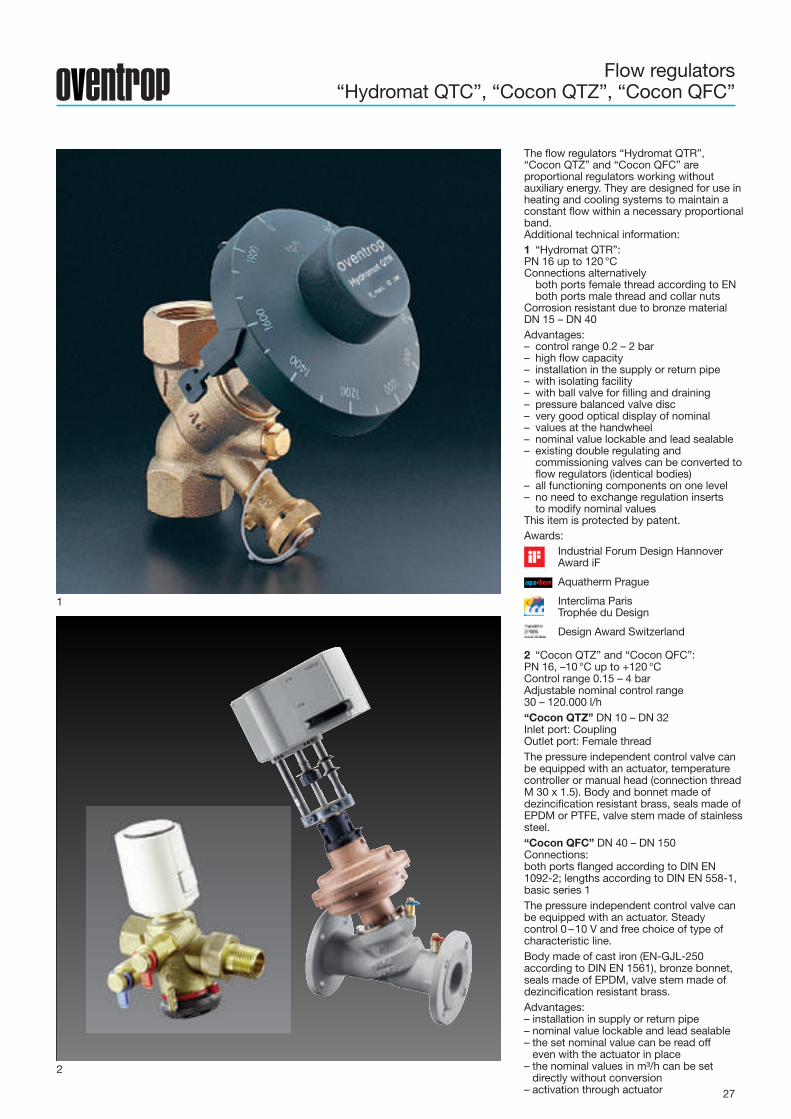
The flow regulators “Hydromat QTR”,“Cocon QTZ” and “Cocon QFC” areproportional regulators working withoutauxiliary energy. They are designed for use inheating and cooling systems to maintain aconstant flow within a necessary proportionalband.Additional technical information:1 “Hydromat QTR”:PN 16 up to 120 °CConnections alternativelyboth ports female thread according to ENboth ports male thread and collar nuts
Corrosion resistant due to bronze materialDN 15 – DN 40Advantages:– control range 0.2 – 2 bar– high flow capacity– installation in the supply or return pipe– with isolating facility– with ball valve for filling and draining– pressure balanced valve disc– very good optical display of nominal– values at the handwheel– nominal value lockable and lead sealable– existing double regulating andcommissioning valves can be converted toflow regulators (identical bodies)
– all functioning components on one level– no need to exchange regulation insertsto modify nominal values
This item is protected by patent.Awards:
Industrial Forum Design HannoverAward iF
Aquatherm Prague
Interclima ParisTrophée du Design
Design Award Switzerland
2 “Cocon QTZ” and “Cocon QFC”:PN 16, –10 °C up to +120 °CControl range 0.15 – 4 barAdjustable nominal control range30 – 120.000 l/h“Cocon QTZ” DN 10 – DN 32Inlet port: CouplingOutlet port: Female threadThe pressure independent control valve canbe equipped with an actuator, temperaturecontroller or manual head (connection threadM 30 x 1.5). Body and bonnet made ofdezincification resistant brass, seals made ofEPDM or PTFE, valve stem made of stainlesssteel.“Cocon QFC” DN 40 – DN 150Connections:both ports flanged according to DIN EN1092-2; lengths according to DIN EN 558-1,basic series 1The pressure independent control valve canbe equipped with an actuator. Steadycontrol 0 –10 V and free choice of type ofcharacteristic line.Body made of cast iron (EN-GJL-250according to DIN EN 1561), bronze bonnet,seals made of EPDM, valve stem made ofdezincification resistant brass.Advantages:– installation in supply or return pipe– nominal value lockable and lead sealable– the set nominal value can be read offeven with the actuator in place
– the nominal values in m³/h can be setdirectly without conversion
– activation through actuator
2

28
Pressure independent control valve with automatic flow control“Cocon QTZ”
1
2
3
1 The Oventrop pressure independentcontrol valve “Cocon QTZ” is a valvecombination consisting of an automaticregulator (nominal value manuallyadjustable) and a regulating valve. Thepressure independent control valve can beequipped with an actuator, temperaturecontroller or manual head (connectionthread M 30 x 1.5).The valve is used for the automatichydronic balancing and temperaturecontrol of appliances or sections of thesystem in chilled ceiling, fan coil,convector, central heating and surfaceheating systems.The valve is made of dezincificationresistant brass and the seals of EPDM orPTFE. The valve stem is made of stainlesssteel.Models:– DN 15 up to DN 32– with or without pressure test points– inlet port: coupling,outlet port: female threadorinlet and outlet port: female thread
2 The desired flow rate is set at thehandwheel (pos. 4). The nominal setting isprotected against unauthorized tamperingwith the help of the handwheel whichengages automatically. This setting can beadditionally secured by inserting thelocking ring. During low demand periods,regulation can be carried out with the helpof an actuator or temperature controllerwhich can bescrewed onto the valve.The illustrated section of the “Cocon QTZ”pressure independent control valve showsthree pressure ranges.“p1” is the inlet and “p3” the outletpressure of the valve. “p2” is the pressureactuating the diaphragm unit andmaintaining the differential pressure“p2”–“p3” at a constant level.3 The pressure independent control valve“Cocon QTZ” has a linear characteristicline which is advantageous when usingactuators (electrothermal or electromotive)which also have a linear stroke behaviour.In general, the valve may also be combinedwith a temperature controller.Advantages:– constant, high valve authority– reduced dimensions– even with the actuator in place, therequired nominal values can be set
– the set nominal value can be read offeven with the actuator in place
– excellent optical display of the set valuesin any installation position
– the nominal values in l/h can be setdirectly without conversion. The nominalvalue range of the valve is imprinted onthe handwheel in a prominent position.
– the locking ring can be lead sealed tosecure the setting from unauthorisedaccess
– the pump setting can be optimised withthe help of a flow-meter (e. g. “OV-DMC2”) which is connected to the pressuretest points of the valve. For this purpose,the pump head is reduced until thepressure independent control valves“Cocon QTZ” are just working within thecontrol range
Flow rate V [l/h]
max.0
100
Effectivevalvelift[%]
Regulating valve
Sleeve
Diaphragm unit
Diaphragm
Balancing valve unit
Handwheel
p3
p1
p2

29
2
Regulating valve“Cocon 2TZ”
1
3
4
1 Regulating valve “Cocon 2TZ”for chilled and radiant ceilings(illustr. with measuring technique “classic”)The calculated flow rate for a givendifferential pressure is set at the regulatingvalve “Cocon 2TZ”. Moreover, it serves toregulate the room temperature with the helpof an electrothermal or electromotiveactuator by an adapted linear characteristicline (not for kvs = 1.8 and 4.5).The valve is installed in heating and coolingsystems and is especially suitable for theinstallation in the return pipe of chilledceiling modules. The flow rate is determinedby measuring the differential pressure viathe integrated metering station by use of theflow-meter “OV-DMC 2”. The flow rate to beregulated can be read off the flow-meter. Tocarry out the hydronic balance, a flow ratedeviation can immediately be readjusted bymodification of the adjustment screw.When actuating the presetting screw, theflow rate to be regulated can be read off theflow-meter if connected to the pressure testpoints of the regulating valve “Cocon 2TZ”.For isolation, the setting screw can becompletely screwed in. When opening untilstop, the value of presetting is restored.Four different models of the regulating valve“Cocon” are available:size 1/2", kvvalue = 0.45size 1/2", kvvalue = 1.0size 1/2", kvvalue = 1.8size 3/4", kvvalue = 4.5
General information:To guarantee a permanent functionalefficiency of the regulation and controlcomponents as well as a permanentavailability of the complete cooling system,preparatory measures should be taken forthe protection of the system.On the one hand, these measures arerelated to possible damages caused bycorrosion, especially in installations withpairings of system components of differentmaterials (copper, steel and plastic) and onthe other hand to the choice and settings ofthe control parameters (e. g. avoiding ofenergy losses in combined heating/coolingsystems).
2 Flow rate depending on the piston strokeof the valveThe chart shows the linear characteristiclines of the regulating valves “Cocon 2TZ”size 1/2", kvs = 0.45, 1.0 and 1.8 and size3/4", kvs = 4.5.
3 Regulating valves “Cocon 2TZ” forchilled and radiant ceilings(illustr. with measuring technique “eco”)Due to the connection thread M 30 x 1.5the valve can be used in combination with:– Oventrop electrothermal actuatorswith two point control
– Oventrop electrothermal actuators(0 –10 V)
– Oventrop electromotive actuators asproportional (0 –10 V) or three pointcontrol
– Oventrop electromotive actuatorsEIB or LON®
4 Measuring device for a quick regulationof the “Cocon 2TZ” valves with measuringtechnique “eco”.
kvs=0.45
kvs=1.0
kvs=1.8
10 20 30 40 50 60 70 80 90 1000
kvs=4.5
1450
1400
1350
650
700
750
800
850
900
1050
1100
1150
1200
1250
1300
0
50
100
150
200
250
300
350
400
450
500
550
600
950
1000
Flow
rate[kg/h]
Piston stroke [%]
Presetting fully opened,constant pressure loss !p=100 mbar

30
Three-way valves “Tri-D TB/TR”, “Tri-D plus TB” and “Tri-M TR”Four-port valve “Tri-M plus TR”
Regulating valve with reversed closing function
1
3
2
5
1 Three-way diverting valve “Tri-D TB”,brassvalve DN 15 with connection threadM 30 x 1.5 for use in heating and coolingsystems, 3 x 3/4" male threaded connection“Euro” cone for different pipes:– threaded tailpipe– solder tailpipe– plug-in tailpipe– compression fittings for copper, plasticand composition pipes
The valve is installed in the return pipe ofchilled ceilings for the regulation of the flowtemperature depending on the dew pointtemperature of the room. Adaptation of theflow temperature of the chilled ceilingwithout interrupting cooling operation. Theinstallation not only of a temperature sensorin the supply pipe of the chilled ceiling butalso of a sensor detecting the humidity ofthe room is required.2 Three-way diverting valve “Tri-D plus TB”with T-piece DN 15 with connection threadM 30 x 1.5 for thermostats and actuators.Male threaded connection 4 x 3/4" to thepipe for different tailpipes and compressionfittings.Application:– chilled ceilings– Fan-Coil units– heating systems– for mass flow distribution with additionalpossibility for room temperature controlor dew point control e. g.
3 Three-way diverting valve “Tri-D TR”,bronzeThree-way mixing valve “Tri-M TR”, bronzeFlat sealing valves sized DN 20, 25, 40 withconnection thread M 30 x 1.5 forthermostats or actuators. The valves areused in heating or cooling systems in whichthe volumes of flow are to be diverted,mixed or changed-over. They are frequentlyused for storage charging connections or inheating systems with two heat producers.4 System illustrationThree-way diverting valve in a chilled ceilinge. g. with electromotive actuator withtemperature sensor in the supply pipe.5 Four-port mixing valve “Tri-M plus TR”,brass Regulating valve for heating andcooling systems as well as for the regulationof suspended and vertical Fan-Coil units.Valve DN 15 with connection threadM 30 x 1.5 for thermostats and actuators.Flat sealing male threaded connection4 x 1/2".Technical data:Max. operating pressure: 10 barMax. differential pressure: 1 barOperating temperature range:–10 °C to +120 °Ckvs values: 0.45/1.0/1.86 “Series KT”Valves for the regulation of Fan-Coil unitsand induction-coil appliances. Oventropthermostatic radiator valves for use inchilled water circuits are proportionalregulators working without auxiliary energy.The room temperature is regulated byvarying the chilled water flow . The valveopens with the temperature at the sensorrising. Angle and straight pattern valves: DN15 to DN 257 ThermostatsThe thermostats with remote control “UniFH” or the Oventrop remote control withadditional remote sensor (see systemillustration, illustr. 7 and 8) are used asregulators.
4
t
t
Raumthermostatmit Temperatur-u. Feuchtefühler
76

31
1
2
3
4 5
Metering stations
The measurement of the flow values and thehydronic regulation of parts of the systemmay also be carried out with the help of themetering stations. They are installed in thedirection of flow in front of the “Hycocon”,"Hydrocontrol” or “Hydromat”.Unlike the measuring technique at thedouble regulating and commissioningvalves (“Hydrocontrol”), the pressuredifferences for the registration of the flowvalues are measured at invariable flow crosssections.The metering stations use the same testpoint connection system as the“Hydrocontrol” valves.When using the Oventrop flow-meter“OV-DMC 2”, in which the flowcharacteristic lines of the metering stationsare stored, the simultaneous indication ofthe flow value on the display is possiblewhen modifying the throttle cross section atthe valve.Flow values for Oventrop metering stationsat 1 bar differential pressure are indicatedon page 13.1 Commissioning set “Hydroset” PN 25Double regulating and commissioning valvewith metering station made ofdezincification resistant brassSizes: DN 15 – DN 502 “Hydrocontrol MTR” PN 25Double regulating and commissioning valvewith integrated metering station (measuringtechnique “classic”) for the hydronicbalancing of heating and cooling systems,with reproducible presetting. Quickregulation of the valve. Steady and directflow indication during the regulation.Pressure test points and handwheel on thesame level.Sizes: DN 15 – DN 503 Stainless steel or cast iron meteringstation for installation between flangesSizes: DN 65 – DN 10004 Commissioning set “Hydroset F”Double regulating and commissioning valvewith metering station5 Butterfly valvesWith metering station for installationbetween flangesSizes: DN 32 – DN 400
Pressureloss
!p=[mbar]
Pressureloss
!p=[Pascal]
Flow rate qm [kg/h]
Size DN
Design exampleRequired: Flow value at the metering
stationGiven: Differential pressure via the
metering station = 100 mbarSize DN 25
Solution: Flow value = 2750 kg/h(taken from chart for bronzemetering station)

32
1
5
7
2
6
3 4
8
ActuatorsRoom thermostats
1 Electrothermal actuatorswith connection thread M 30 x 1.5 for roomtemperature control combined with twopoint controls, connection cable 1 m long.Models:– closed with current off 230 V– opened with current off 230 V– closed with current off 24 V– opened with current off 24 V– closed with current off 230 Vwith auxiliary switch
– 0–10 V2 Electromotive actuatorswith connection thread M 30 x 1.5 for roomtemperature control combined withproportional (0–10 V) two or three pointcontrols. Installation in radiant and chilledceiling systems as well as induction coilappliances.Models:– 24 V proportional actuator (0-10 V),with anti-blocking function
– 230 V three point actuator,without anti-blocking function
– 24 V three point actuator,without anti-blocking function
– 230 V two point actuator,without anti-blocking function
3 Electromotive actuatorswith connection thread M 30 x 1.5 systemsEIB, LON® with integrated bus coupling.The electromotive actuators are suitable fora direct connection to the EuropeanInstallation Bus control system and theLONWORKS® networks. The powerabsorption is extremely low, so that aseparate power supply is not needed.4 Room thermostat24 V/230 V, digital, with fan drive.5 Room thermostat230 V with fan drive.6 Room thermostat – clock 230 V androom thermostat 230 V and 24 VRoom temperature control and timedtemperature setback by use of the roomthermostat-clock or the room thermostat(via an external time switch) in combinationwith electrothermal actuators.7 Electronic room thermostat 24 Vrequired when combined with anelectromotive, proportional actuator forindividual room temperature control. Withone analogue outlet 0–10 V each forheating and cooling as well as adjustableneutral zone (0.5–7.5K).8 Dew point control 24 Vrequired in combination with roomthermostats to protect the chilled ceilingsagainst condensation.

33
Combination possibilities of valves and actuators
Item no.
DN
Connection
Closing dimension x [mm]
Δp max [bar]
Valve lift h [mm]
PN
A
B
C
D
E
F
G
H
I
J
K
L
Characteristicparameters for CBC
Demandson
actuators
1012
4..
ETNC
24V/23
0V
2point
digital
11.2
15.8 -
>90
~5min
IP54
+10
0
1012
4..
ETNO
24V/23
0V
2point
digital
11.2
15.8 -
>90
~5min
IP54
+10
0
1012
953
ETNC
24V
steady(0–10V)
analog
ue
11.2
15.8
4,0
>90
~40
s/mm
IP54
+10
0
1012
705
EM
24V
steady(0–10V)
analog
ue
11.2
15.8
0.5-4.0
>90
~15
s/mm
IP40
+10
0
1012
706
EM
24V
steady(0–10V)
analog
ue
11.2
15.8
0.5-4.0
>90
~15
s/mm
IP40
+10
0
1012
708
EM
24V
3point
digital
11.2
15.8 -
>90
~15
s/mm
IP40
+10
0
1012
709
EM
230V
3point
digital
11.2
15.8 -
>90
~15
s/mm
IP40
+10
0
1012
710/11
EM
NO
230V/24
V
2point
digital
11.2
17.0 -
>90
~3s
IP54
+10
0
1156
0..
EM
24V
steady
EIB
/KNX
11.2
15.2
2.6–4.0
>90
~30
s/mm
IP44
+10
0
1157
065
EM
nom.4
8V
steady
LON
11.2
15.2
2.6–4.0
>90
~30
s/mm
IP44
+10
0
1150
665
EM
Migno
n(2x)
steady
OVwireless(En
Ocean)
11.0
15.4 2 >90
~3s/mm
IP20
+90
1150
765
EM
Migno
n(2x)
stead
y(con
troller
integ
rated
)
EnOc
ean(
EEPA
5-20
-01)
11.0
15.4 2 >90
~3s/mm
IP20
+90
Itemno.
Model
"
Operatingcurrent
Operatingbehaviour
Interface
Lowerliftposition[mm]
Upperliftposition[mm]
Pistonstroke[mm]
Operatingpower[mm]
Mediumfloating
Protection
Max.fluidtemperature[°C]
Permissibleinstall.positionRatings
actuators
Illustration(examples)
Valvecharacteristic
line
Actuatorcharacteristic line
Illustration(examples)
Ratingsvalve
Upper liftposition [mm]Lower liftposition [mm]
" NC = closed with current “off” NO = open with current “off”EM = electromotive ET = electrothermal
! Operating behaviour: additionally 4–20 mA / 2–10 V& Valve adapter “Hycocon” (item no. 1012992) required.% kvs-value can be reduced$ Piston stroke ≥ effective valve lift# Valve adapter 1012462 required. Closing press. [N]
min/max.
any
Inverticalto
horizon
talp
osition
,not
susp
ended
1 2 3 4
“Hycocon ETZ” “Hycocon HTZ” “Cocon 2TZ” “Cocon QTZ”
10683–10684 10685–10686 11450–11454 11455–11462
15–25 15–25 /32 /40 15 /20 10/15/20/25/32
M 30 x 1,5 M 30 x 1.5 M 30 x 1.5 M 30 x 1.5
11.8 11.8 11.8 11.8
1 5 /3 /2 1 4
2.2 3 /4 / 4 2.5 / 3.5 2.8 / 2.8 / 2.8 / 3.5 / 4 / 4
16 16 10 16
14.0 or higher 15.8 or higher 14.3 or higher 14.6/15.8 or higher
11.3 or lower 11.3 or lower 11.3 or lower 11.3 or lower
90 / 150 90 / 150 90 / 150 90 / 150
• • • •
• • • •
• • • •
• • • •
• • • •
• • • •
• • • •
• • • •
• • • •
• • • •
•
•
Drive
Pistonstroke
Drive
Pistonstroke
Drive
Pistonstroke
Drive
Pistonstroke
Drive
Pistonstroke
Drive
Pistonstroke
Drive
Pistonstroke
Drive
Pistonstroke
Drive
Pistonstroke
All values are standard values without tolerances
1. Oventrop valves and actuators: see table
2. Oventrop valves with actuators of other manufacturers:With due consideration of the valve parameters,the combination with actuators of othermanufacturers is possible on consultation.h = valvex = lower stroke of the valve
3. Oventrop actuators with valves of other manufacturers:on consultation
4. Integration into the centralised building control system(CBC): The four most important characteristicparameters are shown in the table.
# #
# #
$ $ $ $
Effective piston stroke
Flowrate
Effective piston stroke
Flowrate
Effective piston stroke
Flowrate
Effective piston stroke
Flowrate
“Aktor T 2P L NC”/“Aktor T 2P H NC”
“Aktor T 2P L NO”/“Aktor T 2P H NO”
“Aktor T ST L NC”
“Aktor M ST L”
“Aktor M ST L”
“Aktor M 3P L”
“Aktor M 3P H”
“Aktor M 2P H”/“Aktor M 2P L”
“Aktor M ST EIB”
“Aktor M ST LON”
“Aktor MH CON B”
Drive
Pistonstroke
Drive
Pistonstroke
“Aktor MH ENO B” Drive
Pistonstroke

34
Combination possibilities of valves and actuators
"
5 6 7 8 9 10
“Tri-M plus TR” “Tri-D plus TB” “Tri-DTR/Tri-MTR” “Tri CTR” “Series KTB”
11427.. 11426.. 11302 /11307 11312 11307.. 11417–11419
15 15 20 /25 /40 15-50 20 /25 /40 15 /20 /25
M 30 x 1.5 M 30 x 1.5 M 30 x 1.5 M 30 x 1.5 M 30 x 1.5 M 30 x 1.5
11.8 11.8 11.8 11.8 11.8 12.8
1 1 0.75 /0.5 / 0.2 0.75 /0.5 / 0.2 0.5
2.5 2.5 2.8 2.8 3 2.5
10 16 16 16 16 10
14.3 or higher 14.3 or higher 14.6 or higher 14.6 or higher 14.8 or higher 13.3 or higher
11.3 or lower 11.3 or lower 11.3 or lower 11.3 or lower 11.3 or lower 10.8 or lower
90 / 150 90 / 150 90 / 150 90 / 150 90 / 150 90 / 150
• • • • •
• • • • • •
• • • • •
• • • • •
• • • • •
• • • • •
• • • • •
• • • • • •
• • • • •
• • • • •
Two-way straightpattern valve
!! ! ! !
"
Effective piston stroke
Flow
rate
Effective piston stroke
Flow
rate
Effective piston stroke
Flow
rate
Effective piston stroke
Flow
rate
Effective piston stroke
Flow
rate
Effective piston stroke
Flow
rate

35
Combination possibilities of valves andactuators
Item no.
DN
Connection
Closing dimension x [mm]
Δp max [bar]
Valve lift h [mm]
PN
A
B
C
D
E
F
G
H
Characteristicparameters for CBC
Demandson
actuators
Item.no.
Model
"
Operatingcurrent
Operatingbehaviour
Interface
Lowerliftposition[mm]
Upperliftposition[mm]
Pistonstroke[mm]
Operatingpower[mm]
Mediumfloating
Protection
Max.fluidtemperature[°C]
Permissibleinstall.positionRatings
actuators
Illustration(examples)
Valvecharacteristic
line
Actuatorcharacteristic line
Illustration(examples)
Ratingsvalve
Upper liftposition [mm]Lower liftposition [mm]
" NC = closed with current “off” NO = open with current “off”EM = electromotive ET = electrothermal
! Operating behaviour: additionally 4–20 mA / 2–10 V& Valve adapter “Hycocon” (item no. 1012992) required.% kvs-value can be reduced$ Piston stroke ≥ effective valve lift Closing pressure [N]
min/max
1 2 3 4
“Cocon QTR” “Cocon QFC” “Cocon QFC/QGC” Two-way valve
11461.. 1146149/50 1146151-55/1676251-53 11308../16708..
40/50 40/50 65/80/100/125/150/200 15-150
Squeeze connection Squeeze connection Squeeze connection Squeeze connection
4 4 4 0.7-12.1
10 10 20 / 36 / 40 10 / 30 / 40
16 16 16 16
500 500 2000
• •
•
• •
• •
• •
• • •
• • •
• • •
All values are standard values without tolerances
1. Oventrop valves and actuators: see table
2. Oventrop valves with actuators of other manufacturers:With due consideration of the valve parameters,the combination with actuators of othermanufacturers is possible on consultation.h = valvex = lower stroke of the valve
3. Oventrop actuators with valves of other manufacturers:on consultation
4. Integration into the centralised building control system(CBC): The four most important characteristicparameters are shown in the table.
'( &%!#""
'( &%!#""
'( &%!#""
'( &%!#%"
'( &%!#%"
'( #%!%"
'( #$%!$""
'( #$%!$""
'( &%!#%"'( #$%!$""
Effective piston stroke
Flowrate
Effective piston stroke
Flowrate
Effective piston stroke
Flowrate
Effective piston stroke
Flowrate
1158
010
EM
72.5
82.5
10 500
7.5
s/m
m
IP54
+12
0
1158
011
EM
72.5
82.5
10 500
7.5
s/m
m
IP54
+12
0
1158
030
EM
!
72.5
112.
5
40 2500
2s/
mm
IP66
+12
0
1158
031
72.5
112.
5
40 2000
2s/
mm
IP66
+12
0
1158
032
EM
72.5
112.
5
40 2000
2s/
mm
IP66
+12
0
1158
022
20 1000
2s/
mm
IP54
+12
0
1158
021
20 1000
2s/
mm
IP54
+12
0
1158
020
EM 20 850
9s/
mm
IP54
+12
0
24V
anal
ogue
/dig
ital/d
igita
l
stea
dy
(0-1
0V
)/2p
oint
/3p
oint
Inve
rtic
alto
horiz
onta
lpos
ition
,not
susp
end
ed
EMwithspringreturn
!EMwithspringreturn
!
“Aktor M ST L”
“Aktor M ST L”
“Aktor M ST L”
“Aktor M ST L”
“Aktor M ST L”
“Aktor M ST L”
“Aktor M ST L”
“Aktor M ST L”
Adjustableat the actuators
Adjustableat the actuators
Adjustableat the actuators
Adjustableat the actuators
Adjustableat the actuators
Drive
Pistonstroke
Drive
Pistonstroke
Drive
Pistonstroke

36
Working supportsService
1
2
3
4
36
Productrange3
PR132-EN/30/5.2016/Ro
Printedonpaperfreefrom
chlorinebleaching.
OVENTROP GmbH & Co. KGPaul-Oventrop-Straße 1D-59939 OlsbergGermanyTelephone +49 (0) 29 62 82-0Telefax +49 (0) 29 62 82-450E-Mail [email protected] www.oventrop.com
For an overview of our global presence visitwww.oventrop.de
Further information can be found in theOventrop catalogue “Products”, in thetechnical data sheets as well as on theinternet, product ranges 3 and 5.
Subject to technical modification withoutnotice.
Oventrop supports its partners regardingplanning, completion and regulation ofhydronic systems. Current informationmaterial like catalogues, technical datasheets, system illustrations and colourleaflets as well as DVDs, calculation slidesand software are available.1 Apart from general information on theOventrop products for hydronic balancing,the Oventrop DVD includes data sets,valve illustrations etc.2 Oventrop calculation slides for a rapiddesign of double regulating andcommis-sioning valves, differentialpressure and flow regulators for hydronicbalancing.3 Oventrop/WILO calculation slide for arapid design of hydronic systems.4 Internet address www.oventrop.de withcalculation programmes like OVplan orOVselect.