product specification fpc-bm biometric module
TRANSCRIPT

Product Specification
FPC-BM
Biometric Module
Revision C

Doc number: Revision: Date: 710-FPC-BM C 2017-03-14
Doc name: Approver: Page:
Product Specification Christian Skeppstedt 2(52)
Fingerprint Cards AB
Contents
Overview ........................................................................................................... 4
General Description .......................................................................................................................... 4 Technical Features – Biometric Module ........................................................................................... 5 Technical Features – Fingerprint Sensors ......................................................................................... 5
Functional Description ....................................................................................... 6 Operating Modes .............................................................................................................................. 6 Fingerprint Sensors ........................................................................................................................... 7 Performance Characteristics ............................................................................................................ 8 Verification Times ............................................................................................................................. 8 Template Updates and Limitations................................................................................................... 8 State Machine Diagrams ................................................................................................................... 9
Signal List ......................................................................................................... 10 Sensor Signals ................................................................................................................................. 10 Host Signals .................................................................................................................................... 10 LED Indicators ................................................................................................................................. 11
Electrical Characteristics ................................................................................... 12 Supply Voltage ................................................................................................................................ 12 Supply Current ................................................................................................................................ 12 Maximum Current Consumption and Power Dissipation ............................................................... 13 Digital Inputs ................................................................................................................................... 13 Digital Outputs ................................................................................................................................ 13
Software Command Interface ........................................................................... 14 UART Serial Interface Settings ........................................................................................................ 14 SPI Interface Settings ...................................................................................................................... 14 Command Send Structure .............................................................................................................. 14 Response structure ......................................................................................................................... 15 SPI Timing Requirements ................................................................................................................ 16
Command Tables .............................................................................................. 17 Biometric Commands ..................................................................................................................... 17 Image transfer ................................................................................................................................ 17 Template Handling ......................................................................................................................... 17 Algorithm Settings .......................................................................................................................... 18 Firmware Commands ..................................................................................................................... 18 Communication Commands ........................................................................................................... 18 Power Commands .......................................................................................................................... 18 Miscellaneous Commands .............................................................................................................. 19 Response Bytes ............................................................................................................................... 19
No sensor: API_NO_SENSOR .......................................................................................................... 20 Broken sensor: API_BROKEN_SENSOR ........................................................................................... 20
Command Descriptions .................................................................................... 21 Capture image: API_CAPTURE_IMAGE ........................................................................................... 21 Capture and Enroll (RAM): API_CAPTURE_AND_ENROL_RAM ...................................................... 21 Capture and Verify (RAM): API_CAPTURE_AND_VERIFY_RAM ..................................................... 22 Capture and Identify (FLASH): API_CAPTURE_ AND _IDENTIFY_FLASH ........................................ 22 Enroll (RAM): API_ENROL_RAM .................................................................................................... 23 Verify (RAM): API_VERIFY_RAM .................................................................................................... 23 Verify (FLASH): API_VERIFY_FLASH ................................................................................................ 23 Identify (Few) (FLASH): API_IDENTIFY_FLASH .............................................................................. 24

Doc number: Revision: Date: 710-FPC-BM C 2017-03-14
Doc name: Approver: Page:
Product Specification Christian Skeppstedt 3(52)
Fingerprint Cards AB
Capture image (Finger present): API_CAPTURE_IMAGE_FINGERPRESENT ................................... 24 Enroll (FLASH): API_ENROL_FLASH ................................................................................................ 24 Capture Enroll (FLASH): API_CAPTURE_AND_ENROL_FLASH ........................................................ 25 Cancel Current Command: API_CANCEL ........................................................................................ 25 Upload Image: API_UPLOAD_IMAGE ............................................................................................ 25 Download Image: API_DOWNLOAD_IMAGE ................................................................................. 26 Upload Template: API_UPLOAD_TEMPLATE ................................................................................. 26 Download Template: API_DOWNLOAD_TEMPLATE ..................................................................... 26 Copy Template from RAM to FLASH: API_COPY_TEMPLATE_FROM_RAM_TO_FLASH ................. 26 Upload Template from FLASH: API_UPLOAD_TEMPLATE_FROM_FLASH ..................................... 27 Delete template in RAM: API_DELETE_TEMPLATE_RAM .............................................................. 27 Delete Single Template in FLASH: API_DELETE_SLOT_IN_FLASH .................................................. 27 Delete All Templates in FLASH: API_DELETE_ALL_IN_FLASH ........................................................ 27 Download Template to FLASH: API_DOWNLOAD_TEMPLATE_TO_FLASH ..................................... 28 Security Level (STATIC): API_SECURITY_LEVEL_STATIC .................................................................. 28 Get Current Security Level: API_GET_SECURITY_LEVEL ................................................................. 29 Get Dynamic Update: API_GET_DYNAMIC_UPDATE ...................................................................... 29 Set Dynamic Update: API_SET_DYNAMIC_UPDATE ....................................................................... 29 Get Firmware Version: API_FIRMWARE_VERSION ......................................................................... 30 Set Baud Rate (RAM): API_SET_BAUD_RATE RAM ......................................................................... 30 Set Baud Rate (STATIC): API_SET_BAUD_RATE_STATIC ................................................................. 31 Test Hardware: API_TEST_HARDWARE ......................................................................................... 31 Set Standalone Mode: API_STAND_ALONE .................................................................................... 31 Enter Sleep Mode: API_ENTER_SLEEP_MODE ............................................................................... 32 Enter Power Save Mode: API_ENTER_POWER_SAVE_MODE_RAM............................................... 32 Power Save Mode: (STATIC) API_POWER_SAVE_MODE_STATIC ................................................... 32 Get current power save mode: API_GET_POWER_SAVE_MODE ................................................... 33 Manage Advance Settings: API_ADVANCED_SETTINGS ................................................................ 33
CRC Calculation ................................................................................................ 35
Power Management ......................................................................................... 36
Mechanical Properties................................................................................... 37 Part Drawings – Processor Card ..................................................................................................... 37 Part Drawings – Sensors ................................................................................................................. 39
Integration and Configuration ....................................................................... 44 Processor Card ................................................................................................................................ 44 Pin-pad Configuration ..................................................................................................................... 45 Reference Design Schematic .......................................................................................................... 45 Power Supply Settings .................................................................................................................... 46 Host Communication ...................................................................................................................... 46 External Sensor Connectors............................................................................................................ 46 Unconnected Pins ........................................................................................................................... 48 ESD DRAIN ...................................................................................................................................... 48 Unused Pins .................................................................................................................................... 49
Sensor Integration .......................................................................................................................... 49 Moisture Sensitivity Level ............................................................................................................... 50
Product Identification ................................................................................... 51
Product Updates ........................................................................................... 52 Product Configurations ................................................................................................................... 52

Doc number: Revision: Date: 710-FPC-BM C 2017-03-14
Doc name: Approver: Page:
Product Specification Christian Skeppstedt 4(52)
Fingerprint Cards AB
Overview The FPC-BM module is a biometric fingerprint system, including a robust fingerprint sensor solution and on-board template storage. The biometric module can be used standalone, ready to use out-of-the-box at delivery, or connected to a host CPU over UART or SPI. Simple serial commands are used to enroll and verify.
Application examples
Access control systems
Time & Attendance
Locks, safes
POS terminals
General Description
The FPC-BM can be used in conjunction with either an FPC1020AM touch fingerprint sensor, or an FPC1011F3 area fingerprint sensor, depending on which is deemed most suitable for the intended application. Each FPC sensor has a protective coating which helps to protect the biometric module against ESD, scratches, impact and everyday wear-and-tear. All FPC sensors feature 3D pixel sensing technology that can read virtually any finger; dry or wet.
The FPC-BM includes the following features:
Embedded / stand-alone fingerprint identification system
Compact sensor module package
Protective sensor coating: scratch and ESD resistant
One-to-one verification mode o Matching against 1 multi-template
Identify (Few) verification mode o 50 multi-templates
On-board template storage o Max. 50 multi-templates
Straightforward serial command interface
Finger detect & FPC OneTouch™ wake-up functionality (with FPC1020AM)
EU RoHS compliant
Easy to integrate and minimize time-to-market
The FPC-BM can be integrated into virtually any application and controlled by a host sending basic commands for enrolment and verification via the serial interface. Fingerprint templates are automatically created and stored in the internal flash memory. Templates used for verification can also be imported from an external storage source, including a central database, smartcard, or portable flash memory.

Doc number: Revision: Date: 710-FPC-BM C 2017-03-14
Doc name: Approver: Page:
Product Specification Christian Skeppstedt 5(52)
Fingerprint Cards AB
Technical Features – Biometric Module
An overview of the technical features of the FPC-BM biometric module is shown in Table 1.
*With proper integration as recommended in this specification. See section 11.10.3.
Table 1: Technical features overview
Technical Features – Fingerprint Sensors
An overview of the fingerprint sensors which are compatible with the FPC-BM is shown in Table 2.
SENSOR
FEATURE
FPC1020AM-CM03
FPC1020AM-CM04 (IP67) FPC1011F3
Sensor matrix 192 x 192 pixels 152 x 200 pixels
Number of pixels 36 864 pixels 30 400 pixels
Active sensing area 9.6 x 9.6 mm 10.6 x 14.0 mm
Spatial resolution 508 DPI 363 DPI
Pixel resolution 256 8-bit grayscale levels
Durability 10 million finger placements
Scratch resistance Pencil hardness: 4H
Resistance to household substances
Water, carbonated soft drinks, coffee, oil, petrol, soap, artificial sweat, orange juice
RoHS / ACPEIP EU RoHS 2 / China RoHS
Table 2: Overview of the FPC1020AM and FPC1011F3 sensors.
See section 10.2 for information on the mechanical properties of the sensors in Table 2.
Parameter Description Value Unit
Processor board dimension (W x L x H) 40.2 x 20.2 x
2.65 mm
Supply voltage Regulated 3.3 V
Unregulated 5 V
Current consumption (3.3 V)
Active capture mode Full Speed <70
mA Half Speed 25
Idle mode (default) Typical 10 mA
Sleep mode Finger detection active (FPC1020) 35 µA
Deep Sleep mode Finger detection not active 3.3 µA
ESD* IEC61000-4-2, level X, air discharge > ± 30 kV

Doc number: Revision: Date: 710-FPC-BM C 2017-03-14
Doc name: Approver: Page:
Product Specification Christian Skeppstedt 6(52)
Fingerprint Cards AB
Functional Description The FPC-BM biometric module is a versatile stand-alone fingerprint verification system which consists of two main components: an FPC fingerprint sensor and a processor board.
The FPC-BM processor board acquires the fingerprint image from the fingerprint sensor. The flash memory on the FPC-BM is pre-loaded with firmware from FPC and is used for all biometric operations and template storage.
Operating Modes
FPC-BM can be run in Standalone Mode, or Host Mode when connected to a host over UART or SPI.
The illustration in Figure 1 shows a system overview of the FPC-BM.
FPC-BM Host
Fingerprint Sensor
FPC1020AM
or
FPC1011F3
CPUProcessor Board
Figure 1: FPC-BM system overview
2.1.1 Standalone Mode
FPC-BM is ready to use out-of-the-box at delivery as a standalone biometric module where Standalone mode is activated by default. See section 7.31 for more information on how to toggle standalone mode.
Host Commands
In standalone mode, when a finger is present, the FPC-BM does not respond to commands from the host.
Unsupported Commands
The Capture Image command is not supported in Standalone mode. Standalone mode must be turned off to use this command. For more information on image capture, see section 7.17.1.
2.1.2 Host Mode
The FPC-BM can be used as a slave towards a host. In Host Mode, a host - selected and provided by the customer - executes the main application which interfaces with the FPC-BM biometric module. Requirements on the host processor associated with the module communication are extremely low; therefore, the host processor can be selected entirely to suit the primary application.
Command Interface
The interface between the host and the processor board is based on a simple-to-use serial UART or a 20 MHz SPI command interface. There is no direct interaction between the host processor and the fingerprint sensor in host mode.
Enroll Pin Deactivated
In Host Mode, the FPC-BM is run as a slave and the Enroll pin is deactivated.

Doc number: Revision: Date: 710-FPC-BM C 2017-03-14
Doc name: Approver: Page:
Product Specification Christian Skeppstedt 7(52)
Fingerprint Cards AB
Fingerprint Sensors
The FPC fingerprint sensors (FPC1020AM and FPC1011F3) which are compatible with the FPC-BM are based on capacitive technology and utilize a reflective measurement method. This method requires a galvanic contact point outside the sensor chip – this is achieved by means of a conductive bezel integrated into the sensor package.
To obtain good quality images, it is important that the sensor is correctly mounted in an enclosure. See section 10 for more information on mechanical properties.
2.2.1 Absolute Maximum Ratings
Exposure to absolute maximum rating conditions for extended periods may affect device reliability. Stress beyond the values outline in this section may cause permanent damage to the fingerprints sensors. Operation of the device in conditions beyond those indicated as normal operation in this specification is not implied or supported.
FPC1020AM
The values listed in Table 3 indicate the absolute maximum ratings for the FPC1020AM sensor.
Parameter Absolute maximum value Unit
VDD -0.5 to +2.5 V
VDDIO -0.5 to +4.8 V
VDDA -0.5 to +2.5 V
Operating temperature - 20 to + 60 ̊C
Storage temperature - 45 to + 85 ̊C
Table 3: Absolute maximum ratings FPC1020AM
FPC1011F3
The values listed in Table 4 indicate the absolute maximum ratings for the FPC1011F3 sensor.
Parameter Absolute maximum value Unit
VDD -0.5 to +7.0 V
VDDIO -0.5 to VDD + 0.5 V
Operating temperature - 20 to + 60 ̊C
Storage temperature - 45 to + 85 ̊C
Table 4: Absolute maximum ratings FPC1011F3

Doc number: Revision: Date: 710-FPC-BM C 2017-03-14
Doc name: Approver: Page:
Product Specification Christian Skeppstedt 8(52)
Fingerprint Cards AB
Performance Characteristics
This section describes the performance characteristics for the sensors that are compatible with the FPC-BM. The FPC-BM has three operation levels which directly affect performance characteristics:
High Convenience (Default)
Normal
High Security
The level that is selected determines the level of convenience and security - FRR and FAR – in any given implementation. The FRR and FAR values for the one-to-one verification mode is shown in Table 5.
25+ users
For applications that handle more than 25 users it is recommended to use the Normal or High Security level.
Parameter Condition 1 User Unit
FRR (False-rejection-rate)
High Convenience (Default) 2,5 %
Normal 3 %
High Security 4 %
FAR (False-acceptance-rate)
High Convenience (Default) 0.01 %
Normal 0.002 %
High Security 0.001 %
Table 5: Performance characteristics – FRR / FAR
Verification Times
Typical processing times for the biometric verification process in both full- and half-speed configuration modes are shown is Table 6.
Process Full Speed Half speed
Unit Min Typical Max Min Typical Max
Verification 1:1 - 400 - - 800 - ms
Identify (Few) 1:50 400 500 600 800 900 1000 ms
Table 6 : Biometric processing times
Template Updates and Limitations
A maximum limit of 70,000 user updates can be performed throughout the lifecycle of the FPC-BM. Each of the 7 data sectors is capable of 10k erases per sector (assuming optimal flash usage spread possible through algorithm use). Each multi-template for can be updated a maximum of 20 times (per enrolled finger).
For example, over a 3-year period, this equates to a maximum of approximately 1165 user changes or updates per year. [70k / 20 = 3500 user changes. 3500 / 3 years ~= 1165 user changes / year.]

Doc number: Revision: Date: 710-FPC-BM C 2017-03-14
Doc name: Approver: Page:
Product Specification Christian Skeppstedt 9(52)
Fingerprint Cards AB
State Machine Diagrams
This section contains state machine diagrams for both Standalone and Hosted mode.
2.6.1 Standalone Mode
A state machine diagram for FPC-BM with Standalone mode activated is illustrated in Figure 2.
Idle
Enroll
Erase Identify
Enroll button + Wake-up button
Finger placed on sensor
Enroll button
System Initialize
Figure 2: State machine diagram Standalone mode
2.6.2 Host Mode
A state machine diagram for FPC-BM in Host mode is illustrated in Figure 3.
Idle
Sleep
Power Save
Template update
Idle 5 seconds
Host CMD
Idle 5 seconds
System Initialize
Handle Command
Capture
Enroll
Erase
Identify
Verified OK (from Identify
process)
OK
FAIL
Figure 3: State machine diagram Host mode

Doc number: Revision: Date: 710-FPC-BM C 2017-03-14
Doc name: Approver: Page:
Product Specification Christian Skeppstedt 10(52)
Fingerprint Cards AB
Signal List This section gives an overview of the signals sent between the FPC-BM and a host.
Sensor Signals
This section gives an overview of the signals sent between the FPC-BM and the sensor.
Name ID Signal Type
(relative to FPC-BM)
Min. voltage
[V]
Max. voltage
[V]
Max. current
[mA]
Max. frequency
[MHz]
GND GND Output 0 0 24 DC
Reset (active low)
RST Output GND 3V3 ~ 0 ~ 0
SPI clock SCLK Output GND 3V3 ~ 0 8
SPI MOSI MOSI Output GND 3V3 ~ 0 SCLK
SPI chip select SCS Output GND 3V3 ~ 0 ~ 0
SPI MISO MISO Input GND 3V3 ~ 0 SCLK
Interrupt* INT Input GND 3V3 ~ 0 ~ 0
VDD (1.8 V) 1V8 Output 1.64 1.96 7 DC
Sensor reset (active low)
RST_N Output GND 3V3 ~ 0 ~ 0
Sensor SPI clock SPICLK Output GND 3V3 ~ 0 ~ 0
Sensor SPI MOSI MOSI Output GND 3V3 ~ 0 SCLK
Sensor SPI C.S. CS_N Output GND 3V3 ~ 0 ~ 0
Sensor SPI MISO MISO Input GND 3V3 ~ 0 SCLK
Sensor interrupt INT Input GND 3V3 ~ 0 ~ 0
ESD FPC1011F3 ESD_DRAIN Input ESD_GND n/a n/a n/a
*not applicable for FPC-BM1011
Table 7: Sensor signals
Host Signals
This section gives an overview of the signals sent between the FPC-BM and a host.
Name ID Signal Type (relative to FPC-BM)
Min. voltage
[V]
Max. voltage
[V]
Design current
[mA]
Max. frequency
[MHz]
VDD (unreg.) 5V_IN Input 4.18 6.00 135 DC
VDD (3.3 V in) 3V3_IN Input 3.01 3.59 135 DC
VDD (3.3 V Out) 3V3_OUT Output 3.01 3.59 135 DC
GND GND Input 0 0 135 DC
TX TXD_UART Output GND 3V3 ~ 0 0.1152
RX RXD_UART Input GND 3V3 ~ 0 0.1152
SPI clock host SPICLK_HOST Input GND 3V3 ~ 0 20
SPI MOSI host MOSI_HOST Input GND 3V3 ~ 0 SCLK
SPI chip select host
CS_N_HOST Input GND 3V3 ~ 0 ~ 0
SPI MISO host MISO_HOST Output GND 3V3 ~ 0 SCLK
Verified OK Verified OK Output GND 3V3 8 ~ 0
Reset FTDI Reset FTDI Output GND 3V3 ~ 0 ~ 0
BOOT0 SET BOOT0 SET Input GND 3V3 8 ~ 0
Switch #1 SWITCH1_WAKE_UP Input GND 3V3 ~ 0 ~ 0
Switch #2 SWITCH2_ENROLL Input GND 3V3 ~ 0 ~ 0
Switch #3 SWiTCH3_RESET Input GND 3V3 ~ 0 ~ 0
Table 8: Host signals
Switches
The host system is responsible for handling any ESD events that may happen via the external switches.

Doc number: Revision: Date: 710-FPC-BM C 2017-03-14
Doc name: Approver: Page:
Product Specification Christian Skeppstedt 11(52)
Fingerprint Cards AB
LED Indicators
An LED indicates the current state of the FPC-BM. An overview of the LED behavior including color and LED state (solid or blinking) during biometric procedures is shown in Table 9.
Function State Color LED State
Power On - Blue Solid
Identify (Few)
Wait for Finger Yellow Blinking
Processing captured image Yellow Solid
Identify (Few) Successful Green Solid
Identify (Few) Failed Red Solid
Enroll
Wait for Finger Yellow Blinking
Processing captured image Yellow Solid
Enroll Successful Green Solid
Enroll Failed Red Solid
Delete All templates in FLASH Processing Red Blinking
Done Green Solid
Error See section 3.3.1 Red Blinking
Table 9: LED indicator status
3.3.1 Troubleshooting
Known errors including possible causes and potential workarounds are described in Table 10.
Error Type Color LED State Possible Cause Workaround
HW failure Red Blinking
Voltage too low during boot up Ensure adequate supply voltage
Sensor not connected at startup Connect sensor
Broken sensor Replace sensor
Table 10: HW troubleshooting

Doc number: Revision: Date: 710-FPC-BM C 2017-03-14
Doc name: Approver: Page:
Product Specification Christian Skeppstedt 12(52)
Fingerprint Cards AB
Electrical Characteristics The electrical characteristics of the FPC-BM are described in this chapter. All signals except the power supply rails and ground are 3.3 V or unregulated 5 V.
Supply Voltage
FPC-BM has two supply modes: 3.3 V (regulated, see section 4.1.1) and 5 V (unregulated, see section 4.1.2). Supply voltages for the FPC-BM are shown in Table 11.
Symbol Parameter Minimum Typical Maximum Unit
VDD Core supply, regulated input 3.3 V 3.01 3.3 3.59 V
VDD Unregulated, input 5 V 4.18 5 6 V
Table 11: FPC -BM Supply Voltages
See section 11.4 for more information on power supply settings.
4.1.1 3.3 V Supply Mode (Regulated)
In the 3.3 V regulated power supply mode the supply voltage is connected directly to MCU and sensor.
The supply voltage shall be connected to 3V3_IN at contact J4-3 on the FPC-BM. No supply voltage shall be connected to the 5V_IN at contact J4- 1.
See Figure 17 for an overview of the pin layout.
Ripple and Noise Level
Ripple and noise level must be ≤ 20 mVpp with 20 MHz bandwidth. The rise and fall time of the host power interface must be slower than 20 μs/V at power-up and power-down to ensure MCU integrity.
4.1.2 5 V Supply Mode (Unregulated)
In the 5 V unregulated supply mode, the supply voltage is regulated down to 3V3 through a linear regulator before connection to MCU and sensor.
A power supply of 5 V shall be connected to 5V_IN at contact J4-1 on the FPC-BM. In 5 V supply mode, the regulated 3V3_OUT must be bridged to 3V3_IN, as shown in Figure 19.
No other connection to the 3V3_IN other than the bridge from 3V3_OUT shall be connected.
Ripple and Noise Level
Ripple and noise level must be ≤ 80 mVpp with 20 MHz bandwidth.
Supply Current
Supply current for the FPC-BM is shown in Table 12. It should be noted that the FPC1011F3 sensor does not go into idle mode.
SYMBOL PARAMETER CONDITION Minimum Typical Maximum UNIT
IDD Supply current
Idle* - 10 - mA
Active full speed - 70 - mA
Active half speed - 25 - mA
Sleep - 30 - µA
Deep Sleep - 3.3 - µA
*not applicable for the FPC-BM1011
Table 12: Supply Current
Doc number: Revision: Date: 710-FPC-BM C 2017-03-14
Doc name: Approver: Page:
Product Specification Christian Skeppstedt 13(52)
Fingerprint Cards AB
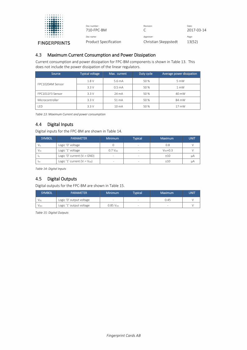
Maximum Current Consumption and Power Dissipation
Current consumption and power dissipation for FPC-BM components is shown in Table 13. This does not include the power dissipation of the linear regulators.
Source Typical voltage Max. current Duty cycle Average power dissipation
FPC1020AM Sensor 1.8 V 5.6 mA 50 % 5 mW
3.3 V 0.5 mA 50 % 1 mW
FPC1011F3 Sensor 3.3 V 24 mA 50 % 40 mW
Microcontroller 3.3 V 51 mA 50 % 84 mW
LED 3.3 V 10 mA 50 % 17 mW
Table 13: Maximum Current and power consumption
Digital Inputs
Digital inputs for the FPC-BM are shown in Table 14.
SYMBOL PARAMETER Minimum Typical Maximum UNIT
VIL Logic ’0’ voltage 0 - 0.8 V
VIH Logic ’1’ voltage 0.7 VDD - VDD+0.3 V
IIL Logic ’0’ current (VI = GND) - - ±10 µA
IIH Logic ’1’ current (VI = VDD) - - ±10 µA
Table 14: Digital Inputs
Digital Outputs
Digital outputs for the FPC-BM are shown in Table 15.
SYMBOL PARAMETER Minimum Typical Maximum UNIT
VOL Logic ’0’ output voltage - - 0.45 V
VOH Logic ’1’ output voltage 0.85 VDD - - V
Table 15: Digital Outputs

Doc number: Revision: Date: 710-FPC-BM C 2017-03-14
Doc name: Approver: Page:
Product Specification Christian Skeppstedt 14(52)
Fingerprint Cards AB
Software Command Interface To communicate with the sensor module, a serial command interface is used between a host processor and the processor board. This interface is designed to be easy to use and performs the basic biometric functions needed in a fingerprint authentication system.
UART Serial Interface Settings
The software settings for the serial protocol using UART are outlined in Table 16.
Parameter Value
Communication speed Range from 9600 to 115200 baud. Factory default baud rate set to 9600 baud.
Format 8 data bits, odd parity, one stop bit.
Bit order Least significant bit first
Table 16: UART interface settings
SPI Interface Settings
The software settings for using SPI commands are outlined in Table 17.
Parameter Value
Communication speed Guaranteed maximum speed: 20 MHz. For details, see SPI timing requirements, in section 5.5.
SPI Mode Mode 3, Clock Polarity High and Clock Phase Rising
Chip Select Active Low
Table 17: SPI interface settings
Command Send Structure
The structure of commands sent from a host are shown in Table 18 and described in this section:
0 1 2 3 4 5
STX IDX-LSB IDX-MSB COMMAND PAYLOAD-LSB PAYLOAD-MSB
Table 18: Structure of commands sent from the host
STX Start byte: 0x02.
IDX-LSB:
Index value, least significant byte.
If no specific value is used for a command setting, the IDX-LSB must be set to zero.
IDX-MSB:
Index value, most significant byte.
If no specific value is used for a command setting, the IDX-MSB must be set to zero.
COMMAND:
Command byte.
PAYLOAD-LSB:
If any additional data is sent, the payload is a counter of how many bytes that will be sent (not including the CRC-code), otherwise zero.
PAYLOAD-MSB:
Payload most significant byte, if no data, set to zero.

Doc number: Revision: Date: 710-FPC-BM C 2017-03-14
Doc name: Approver: Page:
Product Specification Christian Skeppstedt 15(52)
Fingerprint Cards AB
5.3.1 Additional Payload Data
If PAYLOAD != 0, then additional data should follow in the stream outline in Table 19.
6 … n n+1 n+2 n+3 n+4
DATA DATA-… DATA-n CRC-LSB CRC-BYTE2 CRC-BYTE3 CRC-MSB
Table 19: Command Send - Additional Payload Data
The CRC size (4 bytes) is not included in the payload counter. Its value is calculated from all the data bytes, and is used for checking if an error occurred during the transmission. The default for IDX-LSB and IDX-MSB is 0x00, if nothing else is stated.
A new command cannot be sent before a response has been received from the previous command. An exception is when using the API_CANCEL command. See section 7.12 for more information on the cancel command.
Response structure
The structure of the response from the FPC-BM is given in Table 20:
0 1 2 3
STX RESULT PAYLOAD-LSB PAYLOAD-MSB
Table 20: Structure of response from the FPC-BM
STX: Start byte: 0x02
RESULT: Result byte
PAYLOAD-LSB: If any additional data is sent, the payload is a counter of how many bytes that will be sent (not including the CRC-code), otherwise zero.
PAYLOAD-MSB: Payload most significant byte, if no data, set to zero. If PAYLOAD != 0, then additional data should follow in the stream according to Table 21.
4 … n n+1 n+2 n+3 n+4
DATA-1 DATA-… DATA-n CRC-LSB CRC-BYTE2 CRC-BYTE3 CRC-MSB
Table 21: Response Structure Additional Data
The CRC size (4 bytes) is not included in the payload counter. Its value is calculated from all the data bytes, and is used for checking if an error occurred during the transmission.

Doc number: Revision: Date: 710-FPC-BM C 2017-03-14
Doc name: Approver: Page:
Product Specification Christian Skeppstedt 16(52)
Fingerprint Cards AB
SPI Timing Requirements
The SPI interface of the FPC-BM is a slave interface, implying that the host (the master) determines when data is sent to and from the FPC-BM. Since the host cannot know when the FPC-BM has completed processing a given command, a polling process is implemented by the host when trying to read the response for a given command request.
The required implementation of the Request/Response process is as follows:
1. Let the host send the 6 command bytes 2. Wait a minimum of 20 ms for possible payload and CRC 3. Let the host send a byte with value 0x52 to the slave. The host asks the FPC-BM if it is ready to
send the response back to the host. 4. Wait a minimum of 20 ms 5. Check that the received byte is 0x02. If not, the slave is not ready, and requires more time to
complete processing the command. Alternatively, the FPC-BM returns 0x52 to indicate that it is busy.
6. Repeat steps 4-6 until a 0x02 byte is received as response. 7. The 0x02 value is the first byte in the regular response consisting of 4 bytes (plus a possible
payload and CRC).
The SPI data transfer speed is up to 20 MHz for all single -byte transmission.
UART Interface
The requirements outlined in this section do not apply for the UART interface, where the host is aware that the received response is the correct response.

Doc number: Revision: Date: 710-FPC-BM C 2017-03-14
Doc name: Approver: Page:
Product Specification Christian Skeppstedt 17(52)
Fingerprint Cards AB
Command Tables This section gives an overview of the available commands that can be used with the FPC-BM.
Biometric Commands
This section describes the biometric commands for the FPC-BM.
Command HEX Description
API_CAPTURE_IMAGE 0x80 Capture image from sensor (before enroll).
API_CAPTURE_AND_ENROL_RAM 0x81 Enroll into RAM (includes Capture Image)
API_CAPTURE_AND_VERIFY_RAM 0x82 Verify against RAM (includes Capture Image)
API_CAPTURE_AND_VERIFY_FLASH 0x83 Verify against single FLASH slot (includes Capture Image) Set slot number (0 – 49) in IDX
API_CAPTURE_AND_IDENTIFY_FLASH 0x84 Identify (Few) against all FLASH slots (includes Capture Image)
API_ENROL_RAM 0x85 Enroll into RAM
API_VERIFY_RAM 0x86 Verify against RAM
API_VERIFY_FLASH 0x87 Verify against single FLASH slot. Set slot number (0 – 49) in IDX
API_IDENTIFY_FLASH 0x88 Identify (Few) against all FLASH slots
API_CAPTURE_IMAGE_FINGERPRESENT 0x89 Capture Image from sensor (once a finger is present)
API_ENROL_FLASH 0x92 Enroll into FLASH memory
API_CAPTURE_AND_ENROL_FLASH 0x93 Enroll into FLASH memory (includes Capture Image)
Table 22: Biometric Commands
Image transfer
This section describes the image transfer commands for the FPC-BM.
Command HEX Description
API_UPLOAD_IMAGE 0x90 Upload image from RAM to Host
API_DOWNLOAD_IMAGE 0x91 Download image to RAM to Host
Table 23: Image transfer commands
Template Handling
This section describes the template handling commands for the FPC-BM.
Command HEX Descriptions
API_UPLOAD_TEMPLATE 0xA0 Upload template from RAM to host
API_DOWNLOAD_TEMPLATE 0xA1 Download template to RAM to host
API_COPY_TEMPLATE_RAM_TO_FLASH 0xA2 Copy template from RAM to permanent FLASH storage Set slot number (0 to 49) in IDX
API_UPLOAD_TEMPLATE_FROM_FLASH 0xA3 Upload template from single FLASH slot to host. Set slot number (0 to 49) in IDX
API_DELETE_TEMPLATE_RAM 0xA4 Erase template from RAM
API_DELETE_SLOT_IN_FLASH 0xA5 Delete single slot in FLASH Set slot number (0 to 49) in IDX
API_DELETE_ALL_IN_FLASH 0xA6 Delete all FLASH slots
API_DOWNLOAD_TEMPLATE_TO_FLASH 0xA7 Download a template from host to FLASH
Table 24: Template handling commands

Doc number: Revision: Date: 710-FPC-BM C 2017-03-14
Doc name: Approver: Page:
Product Specification Christian Skeppstedt 18(52)
Fingerprint Cards AB
Algorithm Settings
This section describes the algorithm settings commands for the FPC-BM.
Command HEX Description
API_SECURITY_LEVEL_RAM 0xB0
Set security level, setting saved in RAM IDX-LSB: 0x04 = high convenience 0x05 = standard 0x06 = high security
API_SECURITY_LEVEL_STATIC 0xB1 Set security level, setting saved in non-volatile (static) memory.
API_GET_SECURITY_LEVEL 0xB2 Returns the current security level, value sent as payload data.
API_GET_DYNAMIC_UPDATE 0xB3 Returns the current dynamic update setting.
API_SET_DYNAMIC_UPDATE 0xB4 Sets the dynamic update IDX-LSB: 0x00 = Off 0x01 = On
Table 25: Commands for algorithm settings
Firmware Commands
This section describes the firmware commands for the FPC-BM.
Command HEX Description
API_FIRMWARE_VERSION 0xC0 Retrieve the version string for this device
Table 26: Firmware commands
Communication Commands
This section describes the communication commands for the FPC-BM.
Command HEX Description
API_SET_BAUD_RATE_RAM 0xD0 Set baud rate, setting saved in RAM. See section 7.28.
API_SET_BAUD_RATE_STATIC 0xD1 Set baud rate, setting saved in non-volatile static Flash memory. See section 7.29
API_TEST_HARDWARE 0xD2 Test hardware components
Table 27: Communication commands
Power Commands
This section describes the commands for power settings for the FPC-BM.
Command HEX Description
API_ENTER_SLEEP_MODE 0xE1 Enter sleep mode (wake up by activating proper pin)
API_GET_POWER_SAVE_MODE 0xE5
Get current power save mode, value sent as payload data: IDX-MSB: 0x00 = Frequency 0x01 = LED 0x02 = Sleep Mode 0x03 = Sensor wake up (detection frequency)
API_POWER_SAVE_MODE_RAM 0xE2
Set power save mode, setting saved in RAM IDX-MSB: 0x00 = Frequency 0x01 = LED 0x02 = Sleep Mode 0x03 = Sensor wake up (detection frequency) IDX-LSB (frequency): 0x00 = Half 0x01 = Full IDX-LSB (LED): 0x00 = On 0x01 = Mode 0x02 = Off IDX-LSB (sleep mode): 0x00 = Run

Doc number: Revision: Date: 710-FPC-BM C 2017-03-14
Doc name: Approver: Page:
Product Specification Christian Skeppstedt 19(52)
Fingerprint Cards AB
0x01 = Standby 0x02 = Sleep 0x03 Deep Sleep IDX-LSB (sensor wake up): 0x00 = Min (always active) … up to 0xFF = 2000 ms (each step = 7.8 ms)
API_POWER_SAVE_MODE_STATIC 0xE3
Set power save mode, setting saved in non-volatile (static) memory IDX-MSB: 0x00 = Frequency 0x01 = LED 0x02 = Sleep Mode 0x03 = Sensor wake up (detection frequency) IDX-LSB (frequency): 0x00 = Half 0x01 = Full IDX-LSB (LED): 0x00 = On 0x01 = Mode 0x02 = Off IDX-LSB (sleep mode): 0x00 = Run 0x01 = Standby 0x02 = Sleep 0x03 Deep Sleep IDX-LSB (sensor wake up): 0x00 = Min (always active) … up to 0xFF = 2000 ms (each step = 7.8 ms)
Table 28: Power commands
Miscellaneous Commands
This section describes other miscellaneous commands for the FPC-BM.
Command HEX Description
API_CANCEL 0xE0
Cancel ongoing command, only valid for the following commands: API_CAPTURE_AND_ENROL_RAM, API_CAPTURE_AND_VERIFY_RAM, API_CAPTURE_AND_VERIFY_AGAINST_FLASH, API_CAPTURE_AND_IDENTIFY_AGAINST_FLASH
API_ADVANCED_SETTINGS 0xE8 Managing advanced settings, see section 7.36
API_STAND_ALONE 0xEF Toggle stand-alone functionality IDX-LSB: 0x00 = Off 0x01 = On
Table 29: Miscellaneous commands
Response Bytes
This section describes the possible response bytes from the FPC-BM to the host.
Command HEX
API_FAILURE 0x00
API_SUCCESS 0x01
API_NO_FINGER_PRESENT 0x02
API_FINGER_PRESENT 0x03
API_VERIFICATION_OK 0x04
API_VERIFICATION_FAIL 0x05
API_ENROL_OK 0x06
API_ENROL_FAIL 0x07
API_HW_TEST_OK 0x08
API_HW_TEST_FAIL 0x09
API_CRC_FAIL 0x0A
API_PAYLOAD_TOO_LONG 0x0B
API_PAYLOAD_TOO_SHORT 0x0C
API_UNKNOWN_COMMAND 0x0D
API_NO_TEMPLATE_PRESENT 0x0E
API_IDENTIFY_OK 0x0F
Doc number: Revision: Date: 710-FPC-BM C 2017-03-14
Doc name: Approver: Page:
Product Specification Christian Skeppstedt 20(52)
Fingerprint Cards AB
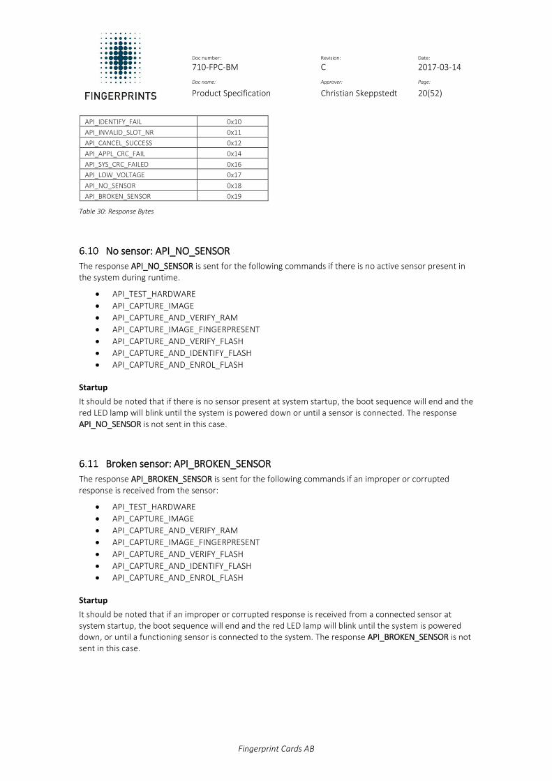
API_IDENTIFY_FAIL 0x10
API_INVALID_SLOT_NR 0x11
API_CANCEL_SUCCESS 0x12
API_APPL_CRC_FAIL 0x14
API_SYS_CRC_FAILED 0x16
API_LOW_VOLTAGE 0x17
API_NO_SENSOR 0x18
API_BROKEN_SENSOR 0x19
Table 30: Response Bytes
No sensor: API_NO_SENSOR
The response API_NO_SENSOR is sent for the following commands if there is no active sensor present in the system during runtime.
API_TEST_HARDWARE
API_CAPTURE_IMAGE
API_CAPTURE_AND_VERIFY_RAM
API_CAPTURE_IMAGE_FINGERPRESENT
API_CAPTURE_AND_VERIFY_FLASH
API_CAPTURE_AND_IDENTIFY_FLASH
API_CAPTURE_AND_ENROL_FLASH
Startup
It should be noted that if there is no sensor present at system startup, the boot sequence will end and the red LED lamp will blink until the system is powered down or until a sensor is connected. The response API_NO_SENSOR is not sent in this case.
Broken sensor: API_BROKEN_SENSOR
The response API_BROKEN_SENSOR is sent for the following commands if an improper or corrupted response is received from the sensor:
API_TEST_HARDWARE
API_CAPTURE_IMAGE
API_CAPTURE_AND_VERIFY_RAM
API_CAPTURE_IMAGE_FINGERPRESENT
API_CAPTURE_AND_VERIFY_FLASH
API_CAPTURE_AND_IDENTIFY_FLASH
API_CAPTURE_AND_ENROL_FLASH
Startup
It should be noted that if an improper or corrupted response is received from a connected sensor at system startup, the boot sequence will end and the red LED lamp will blink until the system is powered down, or until a functioning sensor is connected to the system. The response API_BROKEN_SENSOR is not sent in this case.

Doc number: Revision: Date: 710-FPC-BM C 2017-03-14
Doc name: Approver: Page:
Product Specification Christian Skeppstedt 21(52)
Fingerprint Cards AB
Command Descriptions This chapter describes the individual commands of the main application, along with their parameters, and responses.
Capture image: API_CAPTURE_IMAGE
An image is captured from the fingerprint sensor. The fingerprint image is placed in RAM and can be uploaded by the command API_UPLOAD_IMAGE. Calculation is done on the image to determine if a finger is present or not present on the sensor. No payload is sent with this command.
Response command
• API_NO_FINGER_PRESENT = No finger present on sensor
• API_FINGER_PRESENT = Finger present on sensor
• API_BROKEN_SENSOR = Improper or corrupted response from sensor
No payload is received with the response from this command.
7.1.1 Standalone Mode
Capture Image is not supported in Standalone mode. To use the API_CAPTURE_IMAGE command, the API_STAND_ALONE setting must be turned off (command sequence: 0x02 0x00 0x00 0xEF 0x00 0x00).
See section 7.31 for more information on API_STAND_ALONE.
Capture and Enroll (RAM): API_CAPTURE_AND_ENROL_RAM
An image is captured from the fingerprint sensor and enrolment of the image is performed. See Table 31 for the number of finger placements required during enroll.
Sensor Number of finger placements during enroll
FPC1011 1
FPC1020 8
Table 31: Finger placements during enrolment
Images are captured in a loop from the sensor until a finger is present. The command waits for “finger present” before it starts enrolment. No payload is sent with this command.
The command returns with response when the enrolment is complete or if the enrolment fails for any reason. After enrolment, the template is stored in RAM and can be uploaded or moved to FLASH storage.
Response command
• API_ENROL_OK = Enrolment successful
• API_ENROL_FAIL = Enrolment failed
• API_CANCEL_SUCCESS = API_CANCEL successful, or timeout of 6 seconds per finger placement.
No payload is received with the response from this command.
Cancel operation
It is possible to cancel the current enroll operation by sending the command API_CANCEL. This cancels the enrolment and the device returns to its normal command loop.
See Section 7.12 for more information on the cancel command.

Doc number: Revision: Date: 710-FPC-BM C 2017-03-14
Doc name: Approver: Page:
Product Specification Christian Skeppstedt 22(52)
Fingerprint Cards AB
Capture and Verify (RAM): API_CAPTURE_AND_VERIFY_RAM
A template must be present in RAM before starting the verification, (use one of the following commands: API_DOWNLOAD_TEMPLATE, API_CAPTURE_ENROL_RAM). Thereafter the verification can be started. This command also captures an image from the fingerprint sensor. The command waits for “finger present” before it starts the verification. This means that images are captured in a loop from the sensor until a finger is present. The command returns with response when the verification is complete or if the verification fails for any reason. No payload is sent with this command.
Response command
• API_VERIFICATION_OK = Verification successful
• API_VERIFICATION_FAIL = Verification failed
• API_NO_TEMPLATE_PRESENT = No template present
• API_BROKEN_SENSOR = Improper or corrupted response from sensor
• API_CANCEL_SUCCESS = API_CANCEL successful, or timeout of 6 seconds per finger
placement.
No payload is received with the response from this command. It is possible to cancel the current verification operation by sending the command API_CANCEL. This returns the device to its normal command loop.
See Section 7.12 for more information on the cancel command.
Capture and Identify (FLASH): API_CAPTURE_ AND _IDENTIFY_FLASH
Identification is made against all FLASH slots. This command first captures an image from the fingerprint sensor. The command waits for “finger present” before it starts the identification. This means that images are captured in a loop from the sensor until a finger is present. The command returns with response when the identification is complete or if the identification fails for any reason. No payload is sent with this command.
Response command
• API_ IDENTIFY _OK = Identification successful
• API_ IDENTIFY _FAIL = Identification fails
• API_BROKEN_SENSOR = Improper or corrupted response from sensor
• API_CANCEL_SUCCESS = API_CANCEL successful, or timeout of 6 seconds per finger
placement.
In a successful identification, the slot index is received as payload in two bytes (LSB first) plus the 4 CRC bytes. Maximum number of templates during identification is 50.
It is possible to cancel the current identification operation by sending the API_CANCEL command. The device returns to its normal command loop. See Section 7.12 for more information on the cancel command.

Doc number: Revision: Date: 710-FPC-BM C 2017-03-14
Doc name: Approver: Page:
Product Specification Christian Skeppstedt 23(52)
Fingerprint Cards AB
Enroll (RAM): API_ENROL_RAM
A fingerprint image must be present in RAM before starting the enrolment, either by capturing an image from the fingerprint sensor using the API_CAPTURE_IMAGE command, or the API_DOWNLOAD_IMAGE. The command returns with response when the enrolment is complete or if the enrolment fails for any reason. After enrolment, the template is stored in RAM and can be uploaded or moved to FLASH storage. No payload is sent with this command.
Response command
• API_ENROL_OK = Enrolment successful
• API_ENROL_FAIL = Enrolment failed
No payload is received with the response from this command.
Verify (RAM): API_VERIFY_RAM
A template and a fingerprint image must both be present in RAM before verification starts; use the API_DOWNLOAD_TEMPLATE command, or the API_CAPTURE_ENROL_RAM command.
To process the image, use the API_DOWNLOAD_IMAGE command, or the API_CAPTURE_IMAGE command. The verification can be started after one of these commands has been sent.
The command returns with a response when the verification is complete or if the verification fails for any reason. No payload is sent with this command.
Response command
• API_VERIFICATION_OK = Verification successful
• API_VERIFICATION_FAIL = Verification failed
• API_NO_TEMPLATE_PRESENT = No template present
No payload is received with the response from this command.
Verify (FLASH): API_VERIFY_FLASH
A fingerprint image must be present in RAM before starting the verification, (use one of the following commands: API_DOWNLOAD_IMAGE, API_CAPTURE_IMAGE. The FLASH slot number must be given in the IDX bytes. The command returns with response when the verification is complete or if the verification fails for any reason. No payload is sent with this command.
Response command:
• API_VERIFICATION_OK = Verification successful
• API_VERIFICATION_FAIL = Verification failed
• API_NO_TEMPLATE_PRESENT = No template in given FLASH slot
• API_INVALID_SLOT_NR = Wrong slot number
No payload is received with the response from this command.

Doc number: Revision: Date: 710-FPC-BM C 2017-03-14
Doc name: Approver: Page:
Product Specification Christian Skeppstedt 24(52)
Fingerprint Cards AB
Identify (Few) (FLASH): API_IDENTIFY_FLASH
A fingerprint image must be present in RAM before starting the verification using either the API_DOWNLOAD_IMAGE or API_CAPTURE_IMAGE command.
Identification is performed against all FLASH slots. The command returns with response when the identification is complete or if the identification fails for any reason. No payload is sent with this command.
Response command
• API_ IDENTIFY _OK = Identification successful
• API_ IDENTIFY _FAIL = Identification failed
• API_NO_TEMPLATE_PRESENT = All FLASH slots are empty
During a successful identification, the slot index is received as payload in two bytes (LSB first), plus the 4 CRC bytes.
Maximum number of templates
The FPC-BM has integral support for a maximum of 50 templates.
Capture image (Finger present): API_CAPTURE_IMAGE_FINGERPRESENT
An image is captured from the fingerprint sensor once the system detects a finger on the sensor. The fingerprint image is placed in RAM and can be uploaded by the command API_UPLOAD_IMAGE. No payload is sent with this command. The system waits until a finger is detected, and can only be terminated with the API_CANCEL command.
Response command
• API_FINGER_PRESENT = Finger present on sensor
• API_CANCEL_SUCCESS = API_CANCEL successful, or timeout of 6 seconds
• API_BROKEN_SENSOR = Improper or corrupted response from sensor
No payload is received with the response from this command.
Enroll (FLASH): API_ENROL_FLASH
A fingerprint image must be present in RAM before starting the enrolment, either by capturing an image from the fingerprint sensor using the command API_CAPTURE_IMAGE or by using the Download Image Command, API_DOWNLOAD_IMAGE. The command returns with response when the enrolment is complete or if the enrolment fails for any reason.
After enrolment, the template is stored in FLASH and can be uploaded or moved to FLASH storage. The desired FLASH slot number must be given in the IDX bytes. No payload is sent with this command.
Response command
• API_ENROL_OK = Enrolment successful
• API_ENROL_FAIL = Enrolment failed
• API_INVALID_SLOT_NR = Incorrect FLASH slot number
No payload is received with the response from this command.
Doc number: Revision: Date: 710-FPC-BM C 2017-03-14
Doc name: Approver: Page:
Product Specification Christian Skeppstedt 25(52)
Fingerprint Cards AB
Capture Enroll (FLASH): API_CAPTURE_AND_ENROL_FLASH
This command first captures an image from the fingerprint sensor. The command waits for “finger present” before it starts the verification. This means that images are captured in a loop from the sensor until a finger is present. The command then returns with a response when the enrolment is complete or if the enrolment fails for any reason.
After enrolment, the template is stored in FLASH and can be uploaded or moved to FLASH storage. The desired FLASH slot number must be given in the IDX bytes. No payload is sent with this command.
Response command
• API_ENROL_OK = Enrolment successful
• API_ENROL_FAIL = Enrolment failed
• API_INVALID_SLOT_NR = Incorrect FLASH slot number
• API_BROKEN_SENSOR = Improper or corrupted response from sensor
• API_CANCEL_SUCCESS = API_CANCEL successful, or timeout of 6 seconds per finger placement.
No payload is received with the response from this command.
Cancel Current Command: API_CANCEL
It is possible to cancel the following ongoing commands:
• API_CAPTURE_IMAGE_FINGERPRESENT
• API_CAPTURE_AND_ENROL_RAM
• API_CAPTURE_AND_ENROL_FLASH
• API_CAPTURE_AND_VERIFY_RAM
• API_CAPTURE_AND_VERIFY_FLASH
• API_CAPTURE_AND_IDENTIFY_ FLASH
Important - When the cancel command is sent over SPI, only the following command byte shall be sent: 0xE0. The module will respond with API_CANCEL_SUCCESS and the return to normal command loop. No payload is sent with this command.
Response command
• API_ CANCEL_SUCCESS = Cancel successful
• API_ FAILURE = Cancel failed
No payload is received with the response from this command.
Upload Image: API_UPLOAD_IMAGE
By using this command, it is possible to upload the fingerprint image present in RAM. The response is the API_SUCCESS command followed by the image data. The first byte is the upper left pixel and then data follows row-wise (X-direction). Each pixel has a value of one byte (256 gray scales). There is no image header.
Response command
• API_ SUCCESS = Upload successful
• API_ FAILURE = Upload failed

Doc number: Revision: Date: 710-FPC-BM C 2017-03-14
Doc name: Approver: Page:
Product Specification Christian Skeppstedt 26(52)
Fingerprint Cards AB
Download Image: API_DOWNLOAD_IMAGE
By using this command, it is possible to download a fingerprint image to RAM. The first byte is the upper left pixel and then data follows row-wise (X-direction). Each pixel has value of one byte (256 gray scales).
Response command
• API_ SUCCESS = Download successful
• API_ FAILURE = Download failed
No payload is received with the response from this command.
Upload Template: API_UPLOAD_TEMPLATE
After a successful enrolment, a template is uploaded from RAM using the API_UPLOAD_TEMPLATE command. The response is the API_SUCCESS command followed by the template data. No payload is sent with this command.
Response command
• API_ SUCCESS = Upload successful
• API_ FAILURE = Upload failed
Download Template: API_DOWNLOAD_TEMPLATE
Before verification, a template is downloaded to RAM using the API_DOWNLOAD_TEMPLATE command.
Response command
• API_ SUCCESS = Download successful
• API_ FAILURE = Download failed
No payload is received with the response from this command.
Copy Template from RAM to FLASH: API_COPY_TEMPLATE_FROM_RAM_TO_FLASH
This command copies the template currently in RAM to FLASH. The FLASH slot number must be given in the IDX bytes. No payload is sent with this command.
Response command
• API_ SUCCESS = Template storage successful
• API_ FAILURE = Template storage failed
• API_INVALID_SLOT_NR = Wrong slot number
No payload is received with the response from this command.
Doc number: Revision: Date: 710-FPC-BM C 2017-03-14
Doc name: Approver: Page:
Product Specification Christian Skeppstedt 27(52)
Fingerprint Cards AB
Upload Template from FLASH: API_UPLOAD_TEMPLATE_FROM_FLASH
This command uploads the template from FLASH. The FLASH slot number must be given in the IDX bytes. No payload is sent with this command.
Response command
• API_ SUCCESS = Upload successful
• API_ FAILURE = Upload failed
• API_INVALID_SLOT_NR = Wrong slot number
Delete template in RAM: API_DELETE_TEMPLATE_RAM
This command deletes the template currently stored in RAM. No payload is sent with this command.
Response command
• API_ SUCCESS = Template removal successful
• API_ FAILURE = Template removal failed
No payload is received with the response from this command.
Delete Single Template in FLASH: API_DELETE_SLOT_IN_FLASH
By using the command Delete slot in FLASH one can choose which slot to delete (include slot number in index value of command). No payload is sent with this command.
Response command
• API_ SUCCESS = Template removal successful
• API_ FAILURE = Template removal failed
• API_INVALID_SLOT_NR = Wrong slot number
No payload is received with the response from this command.
Delete All Templates in FLASH: API_DELETE_ALL_IN_FLASH
It is possible to delete all templates in FLASH by issuing the command Delete all in FLASH. No payload is sent with this command.
Response command
• API_ SUCCESS = Template removal successful
• API_ FAILURE = Template removal failed
No payload is received with the response from this command.

Doc number: Revision: Date: 710-FPC-BM C 2017-03-14
Doc name: Approver: Page:
Product Specification Christian Skeppstedt 28(52)
Fingerprint Cards AB
Download Template to FLASH: API_DOWNLOAD_TEMPLATE_TO_FLASH
This command downloads a template from the host directly into the FLASH memory (and into RAM). The FLASH slot number must be given in the IDX bytes. The maximum size of the template is 15728 bytes.
Response command
• API_ SUCCESS = Download successful
• API_ FAILURE = Download failed
• API_INVALID_SLOT_NR = Wrong slot number
No payload is received with the response from this command.
Security Level (STATIC): API_SECURITY_LEVEL_STATIC
The security level to be used during verification and identification can be set by the Set Security Level command. The value of the security level should be set in the index value (IDX-LSB) of the command as seen in Table 32. The factory default security level is set to value 0x04. The value is stored in non-volatile memory and the setting is saved even after reset. The factory default value will be changed.
VALUE (IDXLSB) SECURITY LEVEL
0x04 High convenience (factory default)
0x05 Standard
0x06 High security
Table 32: Security Level Settings
The security level is not stored together with the template. During enrolment, there is no effect when changing the security threshold. The created template will support all security settings. No payload is sent with this command.
Response command
• API_ SUCCESS = New security level set
• API_ FAILURE = Security level out of range
No payload is received with the response from this command.

Doc number: Revision: Date: 710-FPC-BM C 2017-03-14
Doc name: Approver: Page:
Product Specification Christian Skeppstedt 29(52)
Fingerprint Cards AB
Get Current Security Level: API_GET_SECURITY_LEVEL
The API_GET_SECURITY_LEVEL command returns the value of the current security level setting that the FPC-BM is using. No payload is sent with this command.
Response command
The response command is the API_SUCCESS command plus the security level string as payload.
• API_ SUCCESS = Command successful, followed by the security level string
• API_ FAILURE = Command fail
A payload + 4 CRC bytes is received if the request is successful. The payload value, which always is 1 byte corresponds to one of the security levels in Table 33.
VALUE SECURITY LEVEL
0x04 High convenience (factory default)
0x05 Standard
0x06 High security
Table 33: Current security level values
Get Dynamic Update: API_GET_DYNAMIC_UPDATE
The API_GET_DYNAMIC_UPDATE command returns the value of the current dynamic update setting that the module FPC-BM is using. No payload is sent with this command.
Response command
• API_ SUCCESS = Request accepted, dynamic update setting string follows
• API_ FAILURE = Request failed
A payload + 4 CRC bytes will be received in a successful request. The payload value, which always is 1 byte corresponds to one of the update settings in Table 34.
VALUE (IDXLSB) Dynamic update
0x00 Deactivated
0x01 Activated
Table 34: Dynamic update status
Set Dynamic Update: API_SET_DYNAMIC_UPDATE
To activate or deactivate dynamic update, issue the command API_SET_DYNAMIC_UPDATE. No payload is sent with this command.
VALUE (IDXLSB) Dynamic update
0x00 Deactivate
0x01 Activate
Table 35: Dynamic update setting
Response command
• API_ SUCCESS = Request accepted, dynamic update activated or deactivated
• API_ FAILURE = Request failed
No payload is received with the response from this command.

Doc number: Revision: Date: 710-FPC-BM C 2017-03-14
Doc name: Approver: Page:
Product Specification Christian Skeppstedt 30(52)
Fingerprint Cards AB
Get Firmware Version: API_FIRMWARE_VERSION
The API_FIRMWARE_VERSION command returns the firmware version of the main application. No payload is sent with this command.
The response is the API_SUCCESS command followed by the firmware version string.
Response command
• API_ SUCCESS = Request successful, firmware version string follows as payload
• API_ FAILURE = Request failed
A payload + 4 CRC bytes will be received in a successful request. The size of this payload could vary with the version of the firmware.
Set Baud Rate (RAM): API_SET_BAUD_RATE RAM
It is possible to change the baud rate for the serial communication between host and FPC-BM. The default baud rate is 9600. The available baud rates are shown in Table 36.
VALUE (IDXLSB) BAUD RATE
0x00 Currently active baud rate
0x10 9600 (factory default)
0x20 14400
0x30 19200
0x40 28800
0x50 38400
0x60 57600
0x70 76800
0x80 115200
Table 36: Baud Rate values for RAM
The new value is set in the IDX-LSB byte of the command. This new value is stored in RAM and is not saved after a reset. The value will return to the factory default after reset.
Index 0 is the recommended option to ensure that a non-compatible UART speed is not selected.
No payload is sent with this command.
Response command
• API_ SUCCESS = Baud rate change accepted
• API_ FAILURE = Baud rate out of range
No payload is received with the response from this command.
Once a baud rate change has been accepted, the next command must be sent with a new baud rate. However, the response command above is sent with the previous (old) baud rate.

Doc number: Revision: Date: 710-FPC-BM C 2017-03-14
Doc name: Approver: Page:
Product Specification Christian Skeppstedt 31(52)
Fingerprint Cards AB
Set Baud Rate (STATIC): API_SET_BAUD_RATE_STATIC
It is possible to change baud rate for the serial communication between host and FPC-BM. The default baud rate is 9600. The available baud rates are shown in Table 36.
The selected baud rate value is set in the IDX-LSB byte of the command. The value is stored in non-volatile memory and the setting is saved after reset.
Note that if the index 0 is used, the currently active baud rate will be stored. This is the recommended option, since it will ensure that a non-compatible UART speed not is permanently selected. No payload is sent with this command.
Response command:
• API_ SUCCESS = Baud rate change accepted
• API_ FAILURE = Baud rate out of range
No payload is received with the response from this command. Once a baud rate change has been accepted, the next command must be sent with a new baud rate. However, the response command above is sent with the previous (old) baud rate.
Test Hardware: API_TEST_HARDWARE
The API_TEST_HARDWARE command initiates a test of the FPC-BM hardware. No payload is sent with this command.
Response command
• API_HW_TEST_OK = Hardware check successful
• API_HW_TEST_FAIL = Hardware check failed, contact technical support
• API_BROKEN_SENSOR = Improper or corrupted response from sensor
No payload is received with the response from this command.
Set Standalone Mode: API_STAND_ALONE
Standalone mode is toggled by sending the API_STAND_ALONE command. See Table 37 for details. No payload is sent with this command. No payload is received with the response from this command.
VALUE (IDX-LSB) STANDALONE MODE
0x00 Deactivate
0x01 Activate
Table 37: Standalone mode setting
When setting standalone mode, the save location can be set using IDX-MSB. See Table 38 for more information.
VALUE (IDX-MSB) STANDALONE MODE- SAVE LOCATION
0x00 RAM
0x01 STATIC
Table 38: Standalone mode save location
Doc number: Revision: Date: 710-FPC-BM C 2017-03-14
Doc name: Approver: Page:
Product Specification Christian Skeppstedt 32(52)
Fingerprint Cards AB
Response command
• API_ SUCCESS = Request accepted, standalone mode activated or deactivated
• API_ FAILURE = Request failed
No payload is received with the response from this command.
Enter Sleep Mode: API_ENTER_SLEEP_MODE
To enter SLEEP MODE, issue the API_ENTER_SLEEP_MODE command. To wake up the device, a wakeup interrupt must occur. The wakeup interrupt is triggered by the following signal: SWITCH1_WAKEUP (active high).
Before the device enters SLEEP MODE it responds with one of the following:
Response command
• API_ SUCCESS = Request accepted, entering SLEEP MODE
• API_ FAILURE = Request failed
No payload is received with the response from this command.
Enter Power Save Mode: API_ENTER_POWER_SAVE_MODE_RAM
In POWER SAVE MODE the device reduces the clock frequency of the processor by half to lower power consumption. To enter POWER SAVE MODE, issue the API_ENTER_POWER_SAVE_MODE_RAM command. No payload is sent with this command.
Response command
• API_ SUCCESS = Request accepted, entering POWER SAVE MODE
• API_ FAILURE = Request failed
No payload is received with the response from this command.
Power Save Mode: (STATIC) API_POWER_SAVE_MODE_STATIC
In POWER SAVE MODE the module reduces the clock frequency of the processor by half to lower power consumption. The setting is stored in non-volatile memory and the setting is saved even after reset. This means that the factory default setting (value=1) will be changed. No payload is sent with this command.
Enter Power Save Mode
To enter POWER SAVE MODE, issue the command Power Save Mode with the value 0 in the IDX-LSB bytes, as shown in Table 39.
Exit Power Save Mode
To exit POWER SAVE MODE, issue the command Power Save Mode with the value 1 in the IDX-LSB byte, as shown in Table 39.
VALUE (IDX-LSB) POWER SAVE MODE
0 Half Speed
1 Full Speed (factory default)
Table 39: Power save mode setting
Response command
• API_ SUCCESS = Request accepted, entering POWER SAVE MODE
• API_ FAILURE = Request failed
No payload is received with the response from this command.

Doc number: Revision: Date: 710-FPC-BM C 2017-03-14
Doc name: Approver: Page:
Product Specification Christian Skeppstedt 33(52)
Fingerprint Cards AB
Get current power save mode: API_GET_POWER_SAVE_MODE
This command returns the value of the current setting of power save mode. See Table 40 for details. The value is received as payload data. No payload is sent with this command.
VALUE (IDX-LSB) POWER SAVE MODE
0 Half Speed
1 Full Speed (factory default)
Table 40: Current Power Save mode setting
Response command
• API_ SUCCESS = Command OK
• API_ FAILURE = Command fail
The received payload in a successful upload consists of 1 byte plus the 4 CRC bytes.
Manage Advance Settings: API_ADVANCED_SETTINGS
This command is used both to get current, and to set advanced current settings. The advanced settings presently supported include Supply Voltage Control, and disabling the UART host interface.
See Table 41 for command payload values.
7.36.1 Supply Voltage Control
The Supply Voltage Control monitors the supply voltage to ensure that it is at a proper level. The supply voltage threshold is > 2.93 V.
The Supply Voltage Control can be enabled temporarily (in RAM) or statically (in non-volatile Flash memory). If enabled in Flash memory, the setting will remain after a system reset.
Low supply voltage
If Supply Voltage Control is enabled and the supply voltage falls below the specified level, the system will respond to any command with the response code API_LOW_VOLTAGE.
Default setting
The default factory setting for Supply Voltage Control is enabled.
7.36.2 Disable UART
UART can be disabled using the API_ADVANCED_SETTINGS command. The setting can be stored in RAM or in the static Flash memory. The UART interface can only be disabled if the command is sent using an SPI host interface, otherwise the command will fail.
When issuing this command, the host is forced to set the values of both the advanced settings with the same payload byte.

Doc number: Revision: Date: 710-FPC-BM C 2017-03-14
Doc name: Approver: Page:
Product Specification Christian Skeppstedt 34(52)
Fingerprint Cards AB
7.36.3 Command with One Byte Payload
When the API_ADVANCED_SETTINGS command is sent with a one-byte payload, it is used to put the system in the desired mode, by turning on/off individual bits in the payload byte, as seen in Table 41.
Command Payload Value Description
Bit 0 (LSB) = 0 Disable Supply Voltage Control
Bit 0 (LSB) = 1 Enable Supply Voltage Control
Bit 1 = 0 Do not store bit 0 setting statically
Bit 1 = 1 Store bit 0 setting statically
Bit 2 = 0 Enable both UART and SPI
Bit 2 = 1 Disable UART
Bit 3 = 0 Do not store bit 2 setting statically
Bit 3 = 1 Store bit 2 setting statically
Table 41: Command with one-byte payload
7.36.4 Command with No Payload
When the API_ADVANCED_SETTINGS command is sent with no payload, it will return a response including a payload of one byte, which represents the state that the system is currently as seen in Table 42.
Response Value Payload Description
Bit 0 (LSB) = 0 Supply Voltage Control disabled
Bit 0 (LSB) = 1 Supply Voltage Control enabled
Bit 1 Not used
Bit 2 = 0 Both UART and SPI active
Bit 2 = 1 Only SPI active
Table 42: Command with no payload
Response command
• API_SCUCCESS = Command OK
• API_FAILURE = Command Fail
The CRC of 4 bytes are always added to the 1-byte payload. The index bytes of the command structure are not used with this command.

Doc number: Revision: Date: 710-FPC-BM C 2017-03-14
Doc name: Approver: Page:
Product Specification Christian Skeppstedt 35(52)
Fingerprint Cards AB
CRC Calculation The CRC calculation can be implemented as a table of pre-computed effects to ensure efficiency. The CRC value is 32 bits long. The table is indexed by the byte to be encoded and thus the table contains 256 double words (256 x 32 bits).
The CRC algorithm implementation was initially developed by the University of California, Berkeley and its contributors, but has been changed and somewhat simplified to fit the embedded nature of FPC-BM. The algorithm uses the CCITT-32 CRC Polynomial.
The source code for the CRC implementation is available from FPC and can be compiled with limited impact in most environments.

Doc number: Revision: Date: 710-FPC-BM C 2017-03-14
Doc name: Approver: Page:
Product Specification Christian Skeppstedt 36(52)
Fingerprint Cards AB
Power Management The FPC-BM uses an external crystal with a frequency of 25 MHz, and uses this clock to internally generate specific frequencies, depending on the current state of the system.
Two separate commands (API_POWER_SAVE_MODE_RAM, and API_POWER_SAVE_MODE_STATIC) allow the user to set the system in two different power management modes:
Full Speed (Power Save Mode=disabled)
Half Speed (Power Save Mode=enabled).
Full Speed Mode
In Full Speed Mode, the processor speed is 168 MHz
Half Speed Mode
In Half Speed Mode, the processor speed is 84 MHz
For more information on the API_POWER_SAVE_MODE_RAM command, see section 7.3.
For more information on the API_POWER_SAVE_MODE_STATIC command, see section 7.4.

Doc number: Revision: Date: 710-FPC-BM C 2017-03-14
Doc name: Approver: Page:
Product Specification Christian Skeppstedt 37(52)
Fingerprint Cards AB
Mechanical Properties This chapter gives an overview of the mechanical properties for the FPC-BM biometric module processor card and compatible sensors.
All measurements are in millimeters.
Dimensional data is based on nominal values.
Part Drawings – Processor Card
The processor card for the FPC-BM is illustrated as schematic part drawings in this section.
10.1.1 Processor Card - Top View
A part drawing for the top view of the FPC-BM processor card is shown in Figure 4.
Figure 4: FPC-BM processor card - top view
10.1.2 Processor Card - Bottom View
A part drawing for the bottom view of the FPC-BM processor card is shown in Figure 5.
Figure 5: FPC-BM processor card - bottom view

Doc number: Revision: Date: 710-FPC-BM C 2017-03-14
Doc name: Approver: Page:
Product Specification Christian Skeppstedt 38(52)
Fingerprint Cards AB
10.1.3 Processor Card - Side View
A part drawing for the side view of the FPC-BM processor card is shown in Figure 6.
Figure 6: FPC-BM processor card – side view
10.1.4 Solder Pads
Physical properties of the solder pads including the solder mask on the PCB are described in this section.
Solder Mask Opening
The solder mask opening is 1.8 x 2.45 mm as illustrated in Figure 7.
Pad Size
The pad metal measures 1.6 x 2.25 mm with 0.1 mm around each side of the pad as shown in Figure 7.
Figure 7: Solder Pad dimensions
Copper Layer Thickness
The thickness of the outer / top copper layer is 35 µm.
The thickness of the inner / bottom copper layer is 35 µm.

Doc number: Revision: Date: 710-FPC-BM C 2017-03-14
Doc name: Approver: Page:
Product Specification Christian Skeppstedt 39(52)
Fingerprint Cards AB
Part Drawings – Sensors
This section gives an overview of the mechanical properties of the sensors that are compatible with the FPC-BM.
10.2.1 Part Drawings - FPC1020AM CM03
The FPC1020AM CM03 configuration is illustrated as schematic part drawings in this section.
FPC1020AM CM03 - Top View
A part drawing for the top view of the FPC1020AM CM03 sensor is shown in Figure 8.
Figure 8: Part Drawing FPC1020AM CM03 – top view
FPC1020AM CM03 - Bottom View
A part drawing for the bottom view of the FPC1020AM CM03 sensor is shown in Figure 9.
Figure 9: Part Drawing FPC1020AM CM03 – bottom view

Doc number: Revision: Date: 710-FPC-BM C 2017-03-14
Doc name: Approver: Page:
Product Specification Christian Skeppstedt 40(52)
Fingerprint Cards AB
FPC1020AM CM03 - Side View
A part drawing for the side view of the FPC1020AM CM03 sensor is shown in Figure 10.
Figure 10: Part Drawing FPC1020AM CM03 – side view
10.2.2 Part Drawings – FPC1020AM CM04
The FPC1020AM CM04 configuration is illustrated as schematic part drawings in this section.
FPC1020AM CM04 - Top View
A part drawing for the top view of the FPC1020AM CM04 sensor is shown in Figure 11.
Figure 11: Part Drawing FPC1020AM CM04 – top view

Doc number: Revision: Date: 710-FPC-BM C 2017-03-14
Doc name: Approver: Page:
Product Specification Christian Skeppstedt 41(52)
Fingerprint Cards AB
FPC1020AM CM04 - Bottom View
A part drawing for the top view of the FPC1020AM CM04 sensor is shown in Figure 12.
Figure 12: Part Drawing FPC1020AM CM04 – bottom view
FPC1020AM CM04 - Side View
A part drawing for the top view of the FPC1020AM CM04 sensor is shown in Figure 13.
Figure 13: Part Drawing FPC1020AM CM04 – side view

Doc number: Revision: Date: 710-FPC-BM C 2017-03-14
Doc name: Approver: Page:
Product Specification Christian Skeppstedt 42(52)
Fingerprint Cards AB
10.2.3 Part Drawings – FPC1011F3
The FPC1011F3 sensor is illustrated as schematic part drawings in this section.
FPC1011F3 - Top View
A part drawing for the top view of the FPC1011F3 sensor is shown in Figure 14.
Figure 14: Part Drawing FPC1011F3 – top view
FPC1011F3 - Bottom View
A part drawing for the top view of the FPC1011F3 sensor is shown in Figure 15.
Figure 15: Part Drawing FPC1011F3 – bottom view
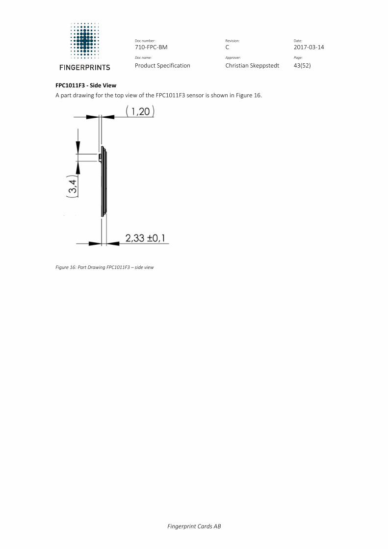
Doc number: Revision: Date: 710-FPC-BM C 2017-03-14
Doc name: Approver: Page:
Product Specification Christian Skeppstedt 43(52)
Fingerprint Cards AB
FPC1011F3 - Side View
A part drawing for the top view of the FPC1011F3 sensor is shown in Figure 16.
Figure 16: Part Drawing FPC1011F3 – side view
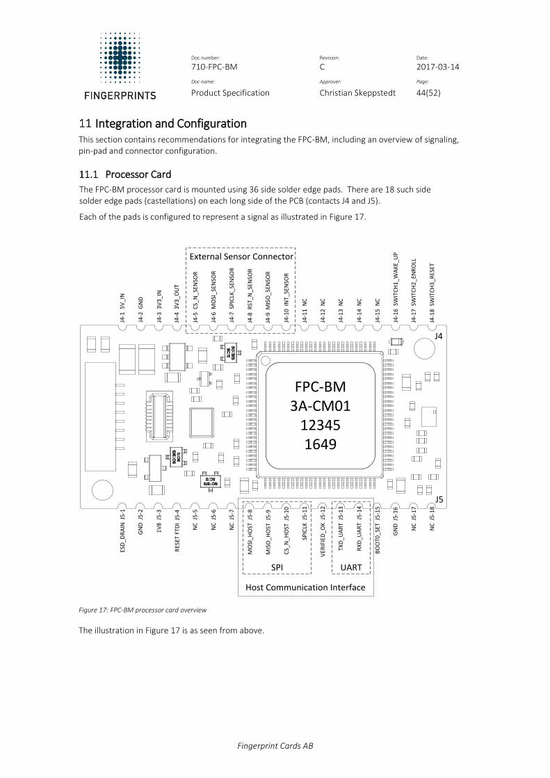
Doc number: Revision: Date: 710-FPC-BM C 2017-03-14
Doc name: Approver: Page:
Product Specification Christian Skeppstedt 44(52)
Fingerprint Cards AB
Integration and Configuration This section contains recommendations for integrating the FPC-BM, including an overview of signaling, pin-pad and connector configuration.
Processor Card
The FPC-BM processor card is mounted using 36 side solder edge pads. There are 18 such side solder edge pads (castellations) on each long side of the PCB (contacts J4 and J5).
Each of the pads is configured to represent a signal as illustrated in Figure 17.
FPC-BM3A-CM01
123451649
J4
J5
J4-1
5V
_IN
J4-2
GN
D
J4-3
3V
3_I
N
J4-4
3V
3_O
UT
J4-5
CS_
N_S
ENSO
R
J4-6
MO
SI_S
ENSO
R
J4-7
SP
ICLK
_SEN
SOR
J4-8
RST
_N_S
ENSO
R
J4-9
MIS
O_S
ENSO
R
J4-1
0 I
NT_
SEN
SOR
J4-1
1 N
C
J4-1
2 N
C
J4-1
3 N
C
J4-1
4 N
C
J4-1
5 N
C
J4-1
6 S
WIT
CH
1_W
AK
E_U
P
J4-1
7 S
WIT
CH
2_E
NR
OLL
J4-1
8 S
WIT
CH
3_R
ESET
ESD
_DR
AIN
J5
-1
GN
D J
5-2
1V
8 J
5-3
RES
ET F
TDI
J5-4
NC
J5
-5
NC
J5
-6
NC
J5
-7
MO
SI_H
OST
J5
-8
MIS
O_H
OST
J5
-9
CS_
N_H
OST
J5
-10
SPIC
LK J
5-1
1
VER
IFIE
D_O
K J
5-1
2
TXD
_UA
RT
J5
-13
RX
D_U
AR
T J
5-1
4
BO
OT0
_SET
J5
-15
GN
D J
5-1
6
NC
J5
-17
NC
J5
-18
SPI UART
External Sensor Connector
Host Communication Interface
Figure 17: FPC-BM processor card overview
The illustration in Figure 17 is as seen from above.

Doc number: Revision: Date: 710-FPC-BM C 2017-03-14
Doc name: Approver: Page:
Product Specification Christian Skeppstedt 45(52)
Fingerprint Cards AB
Pin-pad Configuration
The pin-pad configuration as illustrated in Figure 17 is outlined in Table 43.
Pin number Pad Name [contact J4] Pad Name [contact J5]
1 5V_IN ESD_DRAIN
2 GND GND
3 3V3_IN 1V8
4 3V3_OUT RESET_FTDI
5 CS_N_SENSOR NC
6 MOSI_SENSOR NC
7 SPICLK_SENSOR NC
8 RST_N_SENSOR MOSI_HOST
9 MISO_SENSOR MISO_HOST
10 INT_SENSOR CS_N_HOST
11 NC SPICLK_HOST
12 NC VERIFIED_OK
13 NC TXD_UART
14 NC RXD_UART
15 NC BOOT0_SET
16 SWITCH1_WAKE_UP GND
17 SWITCH2_ENROLL NC
18 SWITCH3_RESET NC
Table 43: Pin-pad configuration
Reference Design Schematic
An example reference design schematic for FPC-BM is shown in Figure 18.
Figure 18: FPC-BM reference design, 5 V power supply

Doc number: Revision: Date: 710-FPC-BM C 2017-03-14
Doc name: Approver: Page:
Product Specification Christian Skeppstedt 46(52)
Fingerprint Cards AB
The schematic in Figure 18 shows the FPC-BM as seen from below. In the reference design presented in Figure 18, the FPC-BM is powered from a 5 V supply. See section 11.4 for more information on power supply settings.
Power Supply Settings
The FPC-BM can be supplied with power from either a 3.3 V or 5 V source.
See section 4.1 for more information on supply voltage.
11.4.1 3.3 V Power Supply
If the FPC-BM is powered from an external 3.3 V source connected to 3V3_IN (J4-3), then the following pins should be left unconnected: 5V_IN (J4-1) and 3V3_OUT (J4-4).
11.4.2 5 V Power Supply
When FPC-BM is powered from a 5 V power supply, it is required that 3V3_OUT (J4-4) and 3V3_IN (J4-3) are connected, as shown in Figure 19.
Figure 19: J4-4 and J4-3 connected for 5 V power supply.
Host Communication
Communication with a Host CPU is available over UART and SPI.
11.5.1 Unused Pins
If the UART and SPI host interfaces are not used, the unused pins shall be connected as follows:
UART
TXD (J5-13)
RXD (J5-14) pull-up to 3V3_IN(J4-3)
SPI
CS_N (J5-10) pull-up to 3V3_IN(J4-3)
SPICLK (J5-11)
MOSI (J5-8)
MISO(J5-9) Pull-down to GND
Recommended Resistor
The recommended resistor value is 680 kΩ.
External Sensor Connectors
An external sensor connector for an FPC1011F3 or FPC1020AM sensor can be implemented using the solder edge pads J4-5 through J4-10 on the FPC-BM processor card. See Figure 18 for reference.
SPI Interface
An SPI interface for external connectors can be connected in parallel to the existing connectors for the FPC1011F3 or FPC1020AM sensor which is mounted on FPC-BM processor card.
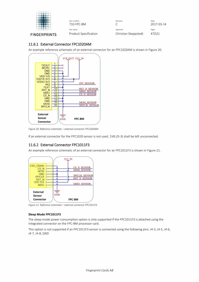
Doc number: Revision: Date: 710-FPC-BM C 2017-03-14
Doc name: Approver: Page:
Product Specification Christian Skeppstedt 47(52)
Fingerprint Cards AB
11.6.1 External Connector FPC1020AM
An example reference schematic of an external connector for an FPC1020AM is shown in Figure 20.
Figure 20: Reference schematic – external connector FPC1020AM
If an external connector for the FPC1020 sensor is not used, 1V8 (J5-3) shall be left unconnected.
11.6.2 External Connector FPC1011F3
An example reference schematic of an external connector for an FPC1011F3 is shown in Figure 21.
Figure 21: Reference schematic – external connector FPC1011F3
Sleep Mode FPC1011F3
The sleep-mode power consumption option is only supported if the FPC1011F3 is attached using the integrated connector on the FPC-BM processor card.
This option is not supported if an FPC1011F3 sensor is connected using the following pins: J4-3, J4-5, J4-6, J4-7, J4-8, GND
FPC-BM
External Sensor Connector
FPC-BM
External Sensor Connector

Doc number: Revision: Date: 710-FPC-BM C 2017-03-14
Doc name: Approver: Page:
Product Specification Christian Skeppstedt 48(52)
Fingerprint Cards AB
11.6.3 Decoupling Capacitors
Decoupling capacitors (C3) and (C4) shall be placed as close as possible to the external sensor connectors, as illustrated in Figure 22.
Figure 22: Decoupling Capacitors
See
Recommended Ratings
The recommended ratings for decoupling capacitors C3 and C4:
100 nF
6.3 V
Unconnected Pins
This section contains information on
11.7.1 No External Sensor Connector
If an external sensor connector is not used, the pins J4-5 through J4-10 shall be left unconnected.
11.7.2 Unused Pins
If the WAKEUP (J4-16), ENROL (J4-17) and RESET (J4-18) pins are not used, these pins shall be soldered to motherboard but are not connected (NC) to maintain mechanical integrity.
RESET and ENROLL Pins
RESET and ENROLL are active low (SIGNAL_N).
11.7.3 VERIFIED_OK pin
If VERIFIED_OK (J5-12) is not used, this pin shall be left unconnected.
ESD DRAIN
The connection between ESD_DRAIN (J5-1) and GND is optional.
11.8.1 FPC1011F3 ESD DRAIN
(J5-1) is connected to pin 8 on the FPC1011 connector mounted on FPC-BM.
6.3 V
6.3 V

Doc number: Revision: Date: 710-FPC-BM C 2017-03-14
Doc name: Approver: Page:
Product Specification Christian Skeppstedt 49(52)
Fingerprint Cards AB
Unused Pins
The following pins are not in use and shall be left unconnected (NC):
J4-11
J4-12
J4-13
J4-14
J4-15
J5-4
J5-5
J5-6
J5-7
J5-15
J5-17
J5-18
Sensor Integration
To maintain biometric performance, the FPC sensors connected to FPC-BM processor card should be mounted or integrated according to the guidelines outlined in this section.
11.10.1 Mechanical Support
The best way to ensure a solid mount is to apply a stable, non-conductive, support to the back side of the sensor module. This non-conductive support can be attached to the entire back side area.
Important! Mechanical force outside the maximum rating may cause permanent damage to the sensor.
11.10.2 Galvanic Contact – Sensor Modules
Due to the conductive bezel on the sensor module, a smooth transition to exterior mechanics can easily be obtained.
Important! Ensure galvanic isolation!
The sensor must be mounted in such way that electrical insulation to adjacent conductive surfaces is achieved. It is also recommended to avoid grounded surfaces nearby the bezel, as this may interfere with sensor operation.
11.10.3 ESD Protection
The FPC-BM has integrated ESD protection. ESD current is deflected across a protective coating on the sensor surface to the bezel surrounding the sensor. From the bezel, the discharged current is conducted via a Transient Voltage Suppressor (TVS) to the local ESD drain node ground pin (GND) on the PCB.
Power Supply Rails
The power supply rails do not need to be protected with an ESD device as they have bulk capacitors that will efficiently store any charge delivered by the ESD.

Doc number: Revision: Date: 710-FPC-BM C 2017-03-14
Doc name: Approver: Page:
Product Specification Christian Skeppstedt 50(52)
Fingerprint Cards AB
Moisture Sensitivity Level
The FPC-BM processor card and connected sensors are moisture-sensitive devices. All components should be handled in accordance with IPC/JEDEC guidelines to avoid damage from moisture absorption and exposure to solder reflow temperatures, which may cause reliability degradation and affect biometric performance.
The FPC-BM module is delivered with an MSL level 3 guarantee (168 hours) based on J-STD-20A. Once soldering has been performed and the FPC-BM module has been mounted, there is reduced risk of degradation from moisture absorption to the device throughout its lifecycle.
Solder Reflow Profile
The solder reflow curve as illustrated in Figure 23 is based on IPC/JEDEC J-STD-020D.
Figure 23: FPC-BM solder reflow curve.
11.11.1 China RoHS
Based on the information from our suppliers FPC-BM has an Environment Friendly Use Period (EFUP) of 50 years.
Part Name
Toxic and Harmful Substances
Pb Hg Cd Cr (VI) PBB PBDE
Resistors X* O* O* O* O* O*
* O: All homogenous materials in the part are under the limits set out in standard GB/T 26572-2011. * X: In at least one homogenous material in the part the substance exceeds the limits set out in standard GB/T 26572-2011.
Table 44: Toxic and harmful substances

Doc number: Revision: Date: 710-FPC-BM C 2017-03-14
Doc name: Approver: Page:
Product Specification Christian Skeppstedt 51(52)
Fingerprint Cards AB
Product Identification To allow for visual recognition and traceability, the FPC-BM is delivered with device name, revision, and manufacturing date marked on the surface of the processor chip, as shown in Figure 24.
FPC-BM3A-CM01
bbbbb1649
Figure 24: FPC-BM marking
The designation used for the labelling in Figure 24 is described in Table 45.
Row Reference label Name Length
(# of characters) Example
1 nnn-nn Device name 6 FPC-BM
2 rr-cccc HW revision & configuration
7 3A-CM01
3 bbbbb Batch number 5 12345
4 yyww Manufacturing date
(year and week) 4 1649
Table 45: Marking designation

Doc number: Revision: Date: 710-FPC-BM C 2017-03-14
Doc name: Approver: Page:
Product Specification Christian Skeppstedt 52(52)
Fingerprint Cards AB
Product Updates An overview of the latest updates to the FPC-BM can be found in this section.
Product Configurations
An overview of the available product configurations for the FPC-BM is shown in Table 46.
Article Number Description
FPC-BM-3C-CM01 FPC Biometric Module processor card, software version 2.0.0
FPC-BM-3B-CM01 FPC Biometric Module processor card, software version 1.0.4
FPC-BM1020-3C-CM02 FPC Biometric Module with FPC1020AM CM04 (IP67), software version 2.0.0
FPC-BM1020-3C-CM01 FPC Biometric Module with FPC1020AM CM03, software version 2.0.0
FPC-BM1020-3B-CM02 FPC Biometric Module with FPC1020AM CM04 (IP67), software version 1.0.4
FPC-BM1020-3B-CM01 FPC Biometric Module with FPC1020AM CM03, software version 1.0.4
FPC-BM1011-3C-CM01 FPC Biometric Module with FPC1011F3, software version 2.0.0
FPC-BM1011-3B-CM01 FPC Biometric Module with FPC1011F3, software version 1.0.4
Table 46: Product Configurations
13.1.1 Document History
The updates and changes between the previous versions of this specification are outlined in Table 47.
Revision Changes
C Signaling information updated; Integration, mechanical drawings, and reference design updated; State machine diagrams added.
B
Initiate Firmware and Firmware Update commands are removed. Performance Characteristics section is updated. Document filename is changed. RoHS and REACH information added.
A New document. CS release FPC-BM.
Table 47: Document History