product submittal/substitution request · • tested in accordancewith astm e 488 and icc-es ac446...
TRANSCRIPT

TO:
PROJECT:
PROJECT LOCATION:
SPECIFIED ITEM:
Section Page Paragraph Description
P R O D U C T S U B M I T TA L / S U B S T I T U T I O N R E Q U E S T E D :
The attached submittal package includes the product description, specifications, drawings, and performance data for use in the evaluation of the request. S U B M I T T E D B Y:
Name: Signature:
Company:
Address:
:xaF:enohpeleT:etaD
F O R U S E B Y T H E A R C H I T E C T A N D / O R E N G I N E E R
�Approved �Approved as Noted �Not Approved
(If not approved, please briefly explain why the product was not accepted.)
By:
Remarks:
Questions or inquiries? Contact us at [email protected], or call 1.800.524.3244
Date:
Product Submittal/Substitution Request
©2015 Powers Fasteners
1

Table of Contents
Powers Fasteners® Bang-It(tm) and Wood-Knocker(tm) Submittal Section:
Product Pages:
- General Information - Installation Instructions - Design Tables - Ordering Information
Code Reports & Agency Listings:
- ICC-ES Approval: ESR-3657 (For Cracked And Uncracked Concrete)
Offline version available for download at www.powersdesignassist.com.
Powers Fasteners developed the Powers Design Assist (PDA) anchor software to enable usersto input technical data into a dynamic model environment-to visualize, consider, and specifyanchors in today's changing engineering climate.
For a demonstration of the latest version of PDA, contact us at www.powers.com or call (800)524-3244.
2
www.powers.com 1
TECH MAN
UAL – MECHAN
iCAL ANCHo
rs ©2015 Po
WErs Vo
LUME 1 – rEV. E
General InformatIon
Section contentS
Mech
an
ica
l a
nch
or
s
General Information ......................1Anchor Materials............................1Material Specifications .................2Installation Instructions ................2Installation Specifications ............3Reference Data (ASD) ....................4Strength Design (SD) .....................6Ordering Information ..................11
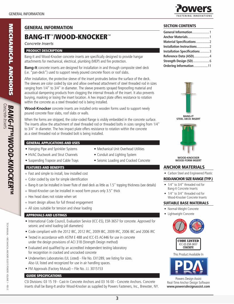
Bang-It Steel Deck InSert
WooD-knockerWooD Form InSert
Anchor MAteriAls• CarbonSteelandEngineeredPlastic
rod/Anchor size rAnge (tYP.)• 1/4"to3/4"threadedrodfor
Bang-ItConcreteInserts• 1/4"to3/4"threadedrodfor
Wood-KnockerConcreteInserts
suitAble bAse MAteriAls• Normal-WeightConcrete• LightweightConcrete
CR
AC
K E D C O N C RE
TE
TE
NS ION ZONE
QU
A L I F I C A T I ON
SEIS
M IC REGION
Code listedICC-eS eSr-3657
concrete
ThisProductAvailableIn
®
PowersDesignAssistReal-TimeAnchorDesignSoftwarewww.powersdesignassist.com
generAl inforMAtion
Bang-It™/Wood-KnocKer™
Concrete Inserts
Product descrIPtIon
Bang-it and Wood-Knocker concrete inserts are specifically designed to provide hangar attachments for mechanical, electrical, plumbing (MEP) and fire protection.
Bang-It concrete inserts are designed for installation in and through composite steel deck (i.e. “pan-deck”) used to support newly poured concrete floors or roof slabs.
After installation, the protective sleeve of the insert protrudes below the surface of the deck. The sleeves are color coded by size and allow overhead attachment of steel threaded rod in sizes ranging from 1/4" to 3/4" in diameter. The sleeve prevents sprayed fireproofing material and acoustical dampening products from clogging the internal threads of the insert. it also prevents burying, masking or losing the insert location. A hex impact plate offers resistance to rotation within the concrete as a steel threaded rod is being installed.
Wood-knocker concrete inserts are installed onto wooden forms used to support newly poured concrete floor slabs, roof slabs or walls.
When the forms are stripped, the color-coded flange is visibly embedded in the concrete surface. The inserts allow the attachment of steel threaded rod or threaded bolts in sizes ranging from 1/4" to 3/4" in diameter. The hex impact plate offers resistance to rotation within the concrete as a steel threaded rod or threaded bolt is being installed.
general aPPlIcatIons and uses
•HangingPipeandSprinklerSystems
•HVACDuctworkandStrutChannels
•SuspendingTrapezeandCableTrays
•MechanicalUnitOverheadUtilities
•ConduitandLightingSystem
•SeismicLoadingandCrackedConcrete
Features and BeneFIts
+ Fastandsimpletoinstall,lowinstalledcost
+ Colorcodedbysizeforsimpleidentification
+ Bang-Itcanbeinstalledinlowerfluteofsteeldeckaslittleas1.5"toppingthickness(seedetails)
+ Wood-Knockercanbeinstalledinwoodformpoursonly3.5"thick
+ Hexheaddoesnotrotatewhenset
+ Insertdesignallowsforfullthreadengagement
+ Allsizessuitablefortensionandshearloading
aPProvals and lIstIngs
•InternationalCodeCouncil,EvaluationService(ICC-ES),ESR-3657forconcrete.Approvedforseismicandwindloading(alldiameters)
•Codecompliantwiththe2012IBC,2012IRC,2009IBC,2009IRC,2006IBCand2006IRC
•TestedinaccordancewithASTME488andICC-ESAC446foruseinconcreteunderthedesignprovisionsofACI318(StrengthDesignmethod)
•Evaluatedandqualifiedbyanaccreditedindependenttestinglaboratoryforrecognitionincrackedanduncrackedconcrete
•UnderwritersLaboratories(ULListed)-FileNo.EX1289,seelistingforsizes.AlsoULlistedandrecognizedforuseinairhandlingspaces.
•FMApprovals(FactoryMutual)–FileNo.J.I.3015153
guIde sPecIFIcatIons
Csi Divisions: 03 15 19 - Cast-in Concrete Anchors and 03 16 00 - Concrete Anchors. Concrete inserts shall be Bang-it and/or Wood-Knocker as supplied by Powers Fasteners, inc., Brewster, NY.
3
www.powers.com 2
materIal SpeCIfICatIonS
TECH
MAN
UAL
– M
ECHA
NiC
AL A
NCH
ors
©20
15 P
oW
Ers
Vo
LUM
E 1
– rE
V. E
Mech
an
ica
l a
nch
or
sMAteriAl sPecificAtions
Bang-ItAnchor Component Component Material
insert Body Aisi 1008 Carbon steel or equivalent
Flange Aisi 1008 Carbon steel or equivalent
spring steel Music Wire
Protective sleeve Engineered Plastic
Zinc Plating AsTM B 633 (Fe/Zn5)Min. Plating requirements for Mild service Condition
Wood-KnockerAnchor Component Component Material
insert Body Aisi 1008 Carbon steel or equivalent
Flange Engineered Plastic
Zinc Plating AsTM B 633 (Fe/Zn5)Min. plating requirements for mild service condition
Material Properties for Threaded Rod
Steel Description Steel Specification(ASTM)
Rod Diameter (inch)
Minimum Yield Strength, fy (ksi)
Minimum Ultimate Strength, fu (ksi)
standard carbon rod A 36 or A 307, Grade C 1/4 to 3/4 36.0 58.0
High strength carbon rod A 193, Grade B7 1/4 to 3/4 105.0 125.0
Allowable Steel Strength for Threaded Rod
AnchorDiameter
din.
(mm)
NominalArea of
Rodin.2
(mm2)
Allowable Tension Allowable Shear
ASTMA36lbs.(kN)
ASTMA307 Grade C
lbs.(kN)
ASTMA193 Grade B7
lbs.(kN)
ASTMA36lbs.(kN)
ASTMA307 Grade C
lbs.(kN)
ASTMA193 Grade B7
lbs.(kN)
1/4(6.4)
0.0491(1.2)
940(4.2)
940(4.2)
2,160(9.7)
485(2.2)
485(2.2)
1,030(4.6)
3/8(9.5)
0.1104(2.8)
2,115(9.5)
2,115(9.5)
4,375(19.7)
1,090(4.9)
1,090(4.9)
2,255(10.1)
1/2(12.7)
0.1963(5.0)
3,755(16.9)
3,755(16.9)
7,775(35.0)
1,940(8.7)
1,940(8.7)
4,055(18.2)
5/8(15.9)
0.3068(7.8)
5,870(26.4)
5,870(26.4)
12,150(54.7)
3,025(13.6)
3,025(13.6)
6,260(28.2)
3/4(19.1)
0.4418(11.2)
8,455(38.0)
8,455(38.0)
17,495(78.7)
4,355(19.6)
4,355(19.6)
9,010(40.5)
1. Allowabletension=fu(Anom)(0.33);Allowableshear=fu(Anom)(0.17)
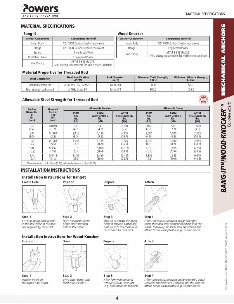
instAllAtion instructionsInstallation Instructions for Bang-Itcreate Hole Position Prepare attach
Step 1Cut (e.g. drill/punch) a hole in the steel deck to the hole size required by the insert.
Step 2Place the plastic sleeve of the insert through hole in steel deck.
Step 3Step on or impact the insert head to engage. Optionally, base plate of insert can also be screwed to steel deck.
Step 4After concrete has reached design strength, install threaded steel element (rod/bolt) into the insert. Trim away for shear load application and attach fixture as applicable (e.g. seismic brace).
Installation Instructions for Wood-KnockerPosition Drive Prepare attach
Step 1Position insert on formwork nails down.
Step 2Drive insert down until flush with the form.
Step 3After formwork removal, remove nails as necessary(e.g. flush mounted fixtures).
Step 4After concrete has reached design strength, install threaded steel element (rod/bolt) into the insert or attach fixture as applicable (e.g. seismic brace).
4

www.powers.com 2
materIal SpeCIfICatIonS
TECH
MAN
UAL
– M
ECHA
NiC
AL A
NCH
ors
©20
15 P
oW
Ers
Vo
LUM
E 1
– rE
V. E
Mech
an
ica
l a
nch
or
sMAteriAl sPecificAtions
Bang-ItAnchor Component Component Material
insert Body Aisi 1008 Carbon steel or equivalent
Flange Aisi 1008 Carbon steel or equivalent
spring steel Music Wire
Protective sleeve Engineered Plastic
Zinc Plating AsTM B 633 (Fe/Zn5)Min. Plating requirements for Mild service Condition
Wood-KnockerAnchor Component Component Material
insert Body Aisi 1008 Carbon steel or equivalent
Flange Engineered Plastic
Zinc Plating AsTM B 633 (Fe/Zn5)Min. plating requirements for mild service condition
Material Properties for Threaded Rod
Steel Description Steel Specification(ASTM)
Rod Diameter (inch)
Minimum Yield Strength, fy (ksi)
Minimum Ultimate Strength, fu (ksi)
standard carbon rod A 36 or A 307, Grade C 1/4 to 3/4 36.0 58.0
High strength carbon rod A 193, Grade B7 1/4 to 3/4 105.0 125.0
Allowable Steel Strength for Threaded Rod
AnchorDiameter
din.
(mm)
NominalArea of
Rodin.2
(mm2)
Allowable Tension Allowable Shear
ASTMA36lbs.(kN)
ASTMA307 Grade C
lbs.(kN)
ASTMA193 Grade B7
lbs.(kN)
ASTMA36lbs.(kN)
ASTMA307 Grade C
lbs.(kN)
ASTMA193 Grade B7
lbs.(kN)
1/4(6.4)
0.0491(1.2)
940(4.2)
940(4.2)
2,160(9.7)
485(2.2)
485(2.2)
1,030(4.6)
3/8(9.5)
0.1104(2.8)
2,115(9.5)
2,115(9.5)
4,375(19.7)
1,090(4.9)
1,090(4.9)
2,255(10.1)
1/2(12.7)
0.1963(5.0)
3,755(16.9)
3,755(16.9)
7,775(35.0)
1,940(8.7)
1,940(8.7)
4,055(18.2)
5/8(15.9)
0.3068(7.8)
5,870(26.4)
5,870(26.4)
12,150(54.7)
3,025(13.6)
3,025(13.6)
6,260(28.2)
3/4(19.1)
0.4418(11.2)
8,455(38.0)
8,455(38.0)
17,495(78.7)
4,355(19.6)
4,355(19.6)
9,010(40.5)
1. Allowabletension=fu(Anom)(0.33);Allowableshear=fu(Anom)(0.17)
instAllAtion instructionsInstallation Instructions for Bang-Itcreate Hole Position Prepare attach
Step 1Cut (e.g. drill/punch) a hole in the steel deck to the hole size required by the insert.
Step 2Place the plastic sleeve of the insert through hole in steel deck.
Step 3Step on or impact the insert head to engage. Optionally, base plate of insert can also be screwed to steel deck.
Step 4After concrete has reached design strength, install threaded steel element (rod/bolt) into the insert. Trim away for shear load application and attach fixture as applicable (e.g. seismic brace).
Installation Instructions for Wood-KnockerPosition Drive Prepare attach
Step 1Position insert on formwork nails down.
Step 2Drive insert down until flush with the form.
Step 3After formwork removal, remove nails as necessary(e.g. flush mounted fixtures).
Step 4After concrete has reached design strength, install threaded steel element (rod/bolt) into the insert or attach fixture as applicable (e.g. seismic brace).
5

www.powers.com 3
TECH MAN
UAL – MECHAN
iCAL ANCHo
rs ©2015 Po
WErs Vo
LUME 1 – rEV. E
InStallatIon SpeCIfICatIonS
Mech
an
ica
l a
nch
or
s
instAllAtion sPecificAtions
Wood-Knocker Cast-In-Place Inserts for Form Pour Concrete
Bang-It Cast-In-Place Inserts for Concrete Filled Steel Deck Floor and Roof Assemblies
2.0
A
A
Nail
Plastic Sleeve
Head Plate
WOODKNOCKER
InternalThread 1/4", 3/8", or 1/2"
Thread Size Marking
InternalThread5/8" or 3/4"
WOODKNOCKER
Thread Size Marking
SECTION A-A SECTION A-A
φ1.50" φ1.75"
A
A
Plastic Sleeve
Head Plate
2.0
BasePlate
Thread Size Marking
Thread Size Marking
BANG-IT BANG-IT
InternalThread 1/4", 3/8", or 1/2"
InternalThread5/8" or 3/4"
SECTION A-A SECTION A-A
1.50" 1.50"
φ1.50"φ1.75"
Bang-It
Dimension NotationNominal Rod/Anchor Size
1/4" 3/8" 1/2" 5/8" 3/4"
Metal Hole saw Diameter (in.) dbit 13/16 or 7/8 1-3/16 or 1-1/4
Metal Hole saw Drilling speed (rpm) - 700-900 700-900 700-900 500-700 500-700
Height of spring (in.) hs 1-7/8 1-7/8 1-7/8 1-7/8 1-7/8
insert Thread Length (in.) - 3/8 5/8 11/16 15/16 1-1/8
Length of sleeve (in.) ℓsl 3-3/8 3-3/8 3-3/8 3-3/8 3-3/8
Thread size, UNC - 1/4-20 3-3/8 1/2-13 5/8-11 3/4-10
overall Length (in.) ℓ 5-7/16 5-7/16 5-7/16 5-7/16 5-7/16
steel Flange Thickness (in.) tsh 1/8 1/8 1/8 1/8 1/8
tsh
hs
ℓsl
ℓ
Wood-Knocker
Dimension NotationNominal Rod/Anchor Size
1/4" 3/8" 1/2" 5/8" 3/4"
insert Thread Length (in.) - 3/8 5/8 11/16 15/16 1-1/8
Plastic Flange Dia. (in.) dpf 1-3/8 1-3/8 1-3/8 1-5/8 1-5/8
Plastic Flange Thickness (in.) - 7/64 7/64 7/64 7/64 7/64
Thread size, UNC - 1/4-20 3/8-16 1/2-13 5/8-11 3/4-10
overall Length (in.) ℓ 2 2 2 2 2
Break-off Nail Length (in.) ℓn 3/4 3/4 3/4 3/4 3/4
steel Flange Thickness (in.) tsh 1/8 1/8 1/8 1/8 1/8
tsh
dpf
6
www.powers.com 4
referenCe Data (aSD)
TECH
MAN
UAL
– M
ECHA
NiC
AL A
NCH
ors
©20
15 P
oW
Ers
Vo
LUM
E 1
– rE
V. E
Mech
an
ica
l a
nch
or
sreference dAtA (Asd)
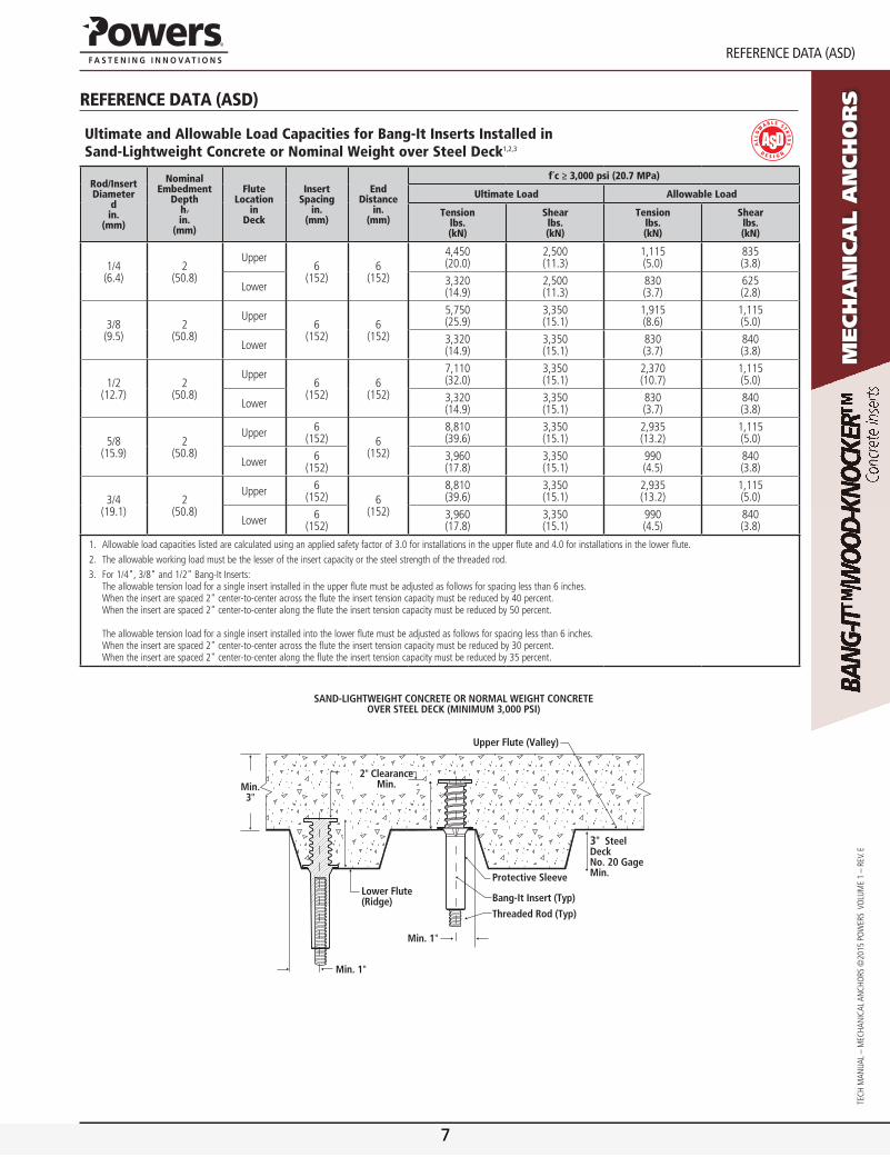
Ultimate and Allowable Load Capacities for Bang-It Inserts Installed in Sand-Lightweight Concrete or Nominal Weight over Steel Deck1,2,3
Rod/InsertDiameter
din.
(mm)
NominalEmbedment
Depthhv
in.(mm)
FluteLocation
inDeck
InsertSpacing
in.(mm)
EndDistance
in.(mm)
f´c ≥ 3,000 psi (20.7 MPa)
Ultimate Load Allowable Load
Tension lbs. (kN)
Shear lbs. (kN)
Tension lbs. (kN)
Shear lbs. (kN)
1/4(6.4)
2(50.8)
Upper6
(152)6
(152)
4,450 (20.0)
2,500(11.3)
1,115(5.0)
835(3.8)
Lower 3,320(14.9)
2,500(11.3)
830(3.7)
625(2.8)
3/8(9.5)
2(50.8)
Upper6
(152)6
(152)
5,750(25.9)
3,350(15.1)
1,915(8.6)
1,115(5.0)
Lower 3,320(14.9)
3,350(15.1)
830(3.7)
840(3.8)
1/2(12.7)
2(50.8)
Upper6
(152)6
(152)
7,110(32.0)
3,350(15.1)
2,370(10.7)
1,115(5.0)
Lower 3,320(14.9)
3,350(15.1)
830(3.7)
840(3.8)
5/8(15.9)
2(50.8)
Upper 6(152) 6
(152)
8,810(39.6)
3,350(15.1)
2,935(13.2)
1,115(5.0)
Lower 6(152)
3,960(17.8)
3,350(15.1)
990(4.5)
840(3.8)
3/4(19.1)
2(50.8)
Upper 6(152) 6
(152)
8,810(39.6)
3,350(15.1)
2,935(13.2)
1,115(5.0)
Lower 6(152)
3,960(17.8)
3,350(15.1)
990(4.5)
840(3.8)
1. Allowableloadcapacitieslistedarecalculatedusinganappliedsafetyfactorof3.0forinstallationsintheupperfluteand4.0forinstallationsinthelowerflute.2. Theallowableworkingloadmustbethelesseroftheinsertcapacityorthesteelstrengthofthethreadedrod.3. For1/4",3/8"and1/2"Bang-ItInserts:
Theallowabletensionloadforasingleinsertinstalledintheupperflutemustbeadjustedasfollowsforspacinglessthan6inches.Whentheinsertarespaced2"center-to-centeracrosstheflutetheinserttensioncapacitymustbereducedby40percent.Whentheinsertarespaced2"center-to-centeralongtheflutetheinserttensioncapacitymustbereducedby50percent.Theallowabletensionloadforasingleinsertinstalledintothelowerflutemustbeadjustedasfollowsforspacinglessthan6inches.Whentheinsertarespaced2"center-to-centeracrosstheflutetheinserttensioncapacitymustbereducedby30percent.Whentheinsertarespaced2"center-to-centeralongtheflutetheinserttensioncapacitymustbereducedby35percent.
Min. 3"
3" Steel Deck No. 20 Gage Min.
Min. 1"
Lower Flute (Ridge)
2" Clearance Min.
SAND-LIGHTWEIGHT CONCRETE OR NORMAL WEIGHT CONCRETE OVER STEEL DECK (MINIMUM 3,000 PSI)
Upper Flute (Valley)
Protective Sleeve
Bang-It Insert (Typ)
Threaded Rod (Typ)
Min. 1"
7
www.powers.com 5
TECH MAN
UAL – MECHAN
iCAL ANCHo
rs ©2015 Po
WErs Vo
LUME 1 – rEV. E
referenCe Data (aSD)
Mech
an
ica
l a
nch
or
s
Ultimate and Allowable Load Capacities for Wood-Knocker Inserts Installedin Normal-Weight Concrete1,2,3
Rod/InsertDiameter
din.
(mm)
NominalEmbedment
Depthhv
in.(mm)
InsertSpacing
in.(mm)
EndDistance
in.(mm)
Minimum Concrete Compressive Strength (f´c)
3,000 psi (20.7 MPa) 4,500 psi (31.1 MPa)
Ultimate Load Allowable Load Ultimate Load Allowable Load
Tension lbs. (kN)
Shear lbs. (kN)
Tension lbs. (kN)
Shear lbs. (kN)
Tension lbs. (kN)
Shear lbs. (kN)
Tension lbs. (kN)
Shear lbs. (kN)
1/4(6.4)
2(50.8)
6(152)
6(152)
3,720(16.7)
1,490(6.9)
1,240(5.6)
495(2.2)
4,250(19.1)
1,610(7.2)
1,415(6.4)
535(2.4)
3/8(9.5)
2(50.8)
6(152)
6(152)
4,820(21.7)
5,330(24.0)
1,605(7.2)
1,775(8.0)
7,190(32.4)
5,620(25.3)
2,395(10.8)
1,875(8.4)
1/2(12.7)
2(50.8)
6(152)
6(152)
4,820(21.7)
7,400(33.3)
1,605(7.2)
2,465(11.1)
7,190(32.4)
8,590(38.7)
2,395(10.8)
2,865(12.9)
5/8(15.9)
2(50.8)
6(152)
6(152)
4,650(20.9)
11,360(51.1)
1,550(7.0)
3,785(17.0)
8,440(38.0)
13,010(58.3)
2,815(12.7)
4,335(19.5)
3/4(19.1)
2(50.8)
6(152)
6(152)
4,650(20.9)
11,360(51.1)
1,550(7.0)
3,785(17.0)
7,350(33.1)
14,590(65.9)
2,450(11.0)
4,865(21.9)
1. Allowableloadcapacitieslistedarecalculatedusinganappliedsafetyfactorof3.0.2. Theallowableworkingloadmustbethelesseroftheinsertcapacityorthesteelstrengthofthethreadedrod.3. Linearinterpolationmaybeusedtodetermineultimateloadsforintermediatecompressivestrengths.
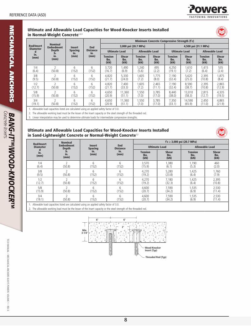
Ultimate and Allowable Load Capacities for Wood-Knocker Inserts Installed in Sand-Lightweight Concrete or Normal-Weight Concrete1,2
Rod/InsertDiameter
din.
(mm)
NominalEmbedment
Depthhv
in.(mm)
InsertSpacing
in.(mm)
EndDistance
in.(mm)
f´c ≥ 3,000 psi (20.7 MPa)
Ultimate Load Allowable Load
Tension lbs. (kN)
Shear lbs. (kN)
Tension lbs. (kN)
Shear lbs. (kN)
1/4(6.4)
2(50.8)
6(152)
6(152)
3,570(15.9)
1,380(6.1)
1,190(5.3)
460(2.0)
3/8(9.5)
2(50.8)
6(152)
6(152)
4,270(19.2)
5,280(23.8)
1,425(6.4)
1,760(7.9)
1/2(12.7)
2(50.8)
6(152)
6(152)
4,270(19.2)
7,180(32.3)
1,425(6.4)
2,395(10.8)
5/8(15.9)
2(50.8)
6(152)
6(152)
4,600(20.7)
7,590(34.2)
1,535(6.9)
2,530(11.4)
3/4(19.1)
2(50.8)
6(152)
6(152)
4,600(20.7)
7,590(34.2)
1,535(6.9)
2,530(11.4)
1. Allowableloadcapacitieslistedarecalculatedusinganappliedsafetyfactorof3.0.2. Theallowableworkingloadmustbethelesseroftheinsertcapacityorthesteelstrengthofthethreadedrod.
Min. 3-1/4"
2"
6"
Wood-Knocker Insert (Typ)
Threaded Rod (Typ)
6"
8

www.powers.com 6
StrenGth DeSIGn (SD)
TECH
MAN
UAL
– M
ECHA
NiC
AL A
NCH
ors
©20
15 P
oW
Ers
Vo
LUM
E 1
– rE
V. E
Mech
an
ica
l a
nch
or
sstrength design (sd)
Wood-Knocker Insert Design Information1,2,3,4,5,6,7
Design Information Symbol Units 1/4-inch 3/8-inch 1/2-inch 5/8-inch 3/4-inch
insert o.D. da (do) in.(mm)
0.7(18)
0.7(18)
0.7(18)
1.0(25)
1.0(25)
insert head net bearing area Abrgin2
(mm2)1.20(762)
1.20(762)
1.20(762)
1.30(839)
1.30(839)
Effective embedment depth hefin.
(mm)1.75(45)
1.75(45)
1.75(45)
1.75(45)
1.75(45)
Minimum member thickness hmin - 3.5(89)
3.5(89)
3.5(89)
3.5(89)
3.5(89)
Effectiveness factor for cracked concrete kc-
(si)24
(10)24
(10)24
(10)24
(10)24
(10)Modification factor for tension strength in uncracked concrete ΨC,n - 1.25 1.25 1.25 1.25 1.25Nominal tension strength of single insert in tension as governed by steel strength Nsa,insert
lb(kN)
10,270(45.7)
10,270(45.7)
9,005(40.1)
12,685(56.4)
13,370(59.5)
Nominal seismic tension strength of single insert in tension as governed by steel strength Nsa,insert,eq
lb(kN)
10,270(45.7)
10,270(45.7)
9,005(40.1)
12,685(56.4)
13,370(59.5)
Nominal steel shear strength of single insert Vsa,insertlb
(kN)10,550(47.0)
10,550(47.0)
10,550(47.0)
9,075(40.4)
9,075(40.4)
Nominal steel shear strength of single insert for seismic loading Vsa,insert,eqlb
(kN)10,550(47.0)
10,550(47.0)
10,550(47.0)
9,075(40.4)
9,075(40.4)
ForSI:1inch=25.4mm,1inch2=635mm2,1pound=0.00445kN,1psi=0.006895MPa.Forpound-inchunit:1mm=0.03937inches.1. Concretemusthaveacompressivestrengthf'cof2,500psiminimum.2. Designofheadedcast-inspecialtyinsertsshallbeinaccordancewiththeprovisionsofACI318AppendixDforcast-inheadedanchors.3. StrengthreductionfactorsfortheinsertsshallbetakenfromACI318-11D.4.3forcast-inheadedanchors.StrengthreductionfactorsforloadcombinationsinaccordancewithACI318
Section9.2governedbysteelstrengthoftheinsertshallbetakenas0.65fortensionand0.60forshear;valuescorrespondtobrittlesteelelements.ThevalueofφapplieswhentheloadcombinationsofSection1605.2oftheIBCorACI318Section9.2areusedinaccordancewithACI318D.4.3.IftheloadcombinationsofACI318AppendixCareused,theappropriatevalueofφmustbedeterminedinaccordancewithACI318D.4.4.
4. Theconcretetensionstrengthofheadedcast-inspecialtyinsertsshallbecalculatedinaccordancewithACI318AppendixD.5. InsertO.D.istheoutsidediameteroftheheadedinsertbody.6. Minimumspacingdistancebetweenanchorsandminimumedgedistanceforcast-inWood-KnockeranchorsshallbeinaccordancewithACI318D.8.7. Thestrengthsshowninthetableareforinsertsonly.Designprofessionalisresponsibleforcheckingthreadedrodorboltstrengthintension,shear,andcombinedtensionandshear,as
applicable.SeeSteelDesignInformationtableforcommonthreadedrodelements.
Bang-It Insert Design Information1,2,3,4,5,6,7,8
Design Information Symbol Units 1/4-inch 3/8-inch 1/2-inch 5/8-inch 3/4-inch
insert o.D. da (do) in.(mm)
0.7(18)
0.7(18)
0.7(18)
1.0(25)
1.0(25)
insert head net bearing area Abrgin2
(mm2)1.20(762)
1.20(762)
1.20(762)
1.30(839)
1.30(839)
Effective embedment depth hefin.
(mm)1.75(45)
1.75(45)
1.75(45)
1.75(45)
1.75(45)
Minimum member thickness hmin - see Deck Figures as applicable
Minimum spacing and edge distances
Upper flute smin, cmin - see ACi 318 section D.8.1 and D.8.2Lower flute smin, cmin - see Deck Figures as applicable
Effectiveness factor for cracked concrete kc-
(si)24
(10)24
(10)24
(10)24
(10)24
(10)Modification factor for tension strength in uncracked concrete ΨC,n - 1.25 1.25 1.25 1.25 1.25Nominal tension strength of single insert in tension as governed by steel strength (4-1/2" W-Deck, B-Deck, 3-7/8" W-Deck) Nsa,insert
lb(kN)
10,440(46.4)
10,440(46.4)
8,240(36.7)
13,415(59.7)
11,985(53.3)
Nominal seismic tension strength of single insert in tension as governed by steel strength (4-1/2" W-Deck, B-Deck, 3-7/8" W-Deck) Nsa,insert,eq
lb(kN)
10,440(46.4)
10,440(46.4)
8,240(36.7)
13,415(59.7)
11,985(53.3)
Nominal steel shear strength of single insert in the soffit of concrete on steel deck, (4-1/2" W-Deck) Vsa,insert,deck
lb(kN)
2,280(10.2)
2,280(10.2)
2,280(10.2)
3,075(13.7)
3,075(13.7)
Nominal steel shear strength of single insert in the soffit of concrete on steel deck, for seismic loading, (4-1/2" W-Deck) Vsa,insert,deck,eq
lb(kN)
2,280(10.2)
2,280(10.2)
2,280(10.2)
2,695(12.0)
2,695(12.0)
Nominal steel shear strength of single insert in the soffit of concrete on steel deck, (B-Deck, 3-7/8" W-Deck) Vsa,insert,deck
lb(kN)
2,080(10.2)
2,080(10.2)
2,080(10.2)
2,975(13.2)
2,975(13.2)
Nominal steel shear strength of single insert in the soffit of concrete on steel deck, for seismic loading, (B-Deck, 3-7/8" W-Deck) Vsa,insert,deck,eq
lb(kN)
2,080(10.2)
2,080(10.2)
2,080(10.2)
2,695(12.0)
2,695(12.0)
ForSI:1inch=25.4mm,1inch2=635mm2,1pound=4.45N,1psi=0.006895MPa.Forpound-inchunit:1mm=0.03937inches.1. Concretemusthaveacompressivestrengthf'cof2,500psiminimum.2. Designofheadedcast-inspecialtyinsertsshallbeinaccordancewiththeprovisionsofACI318AppendixDforcast-inheadedanchors.3. StrengthreductionfactorsfortheinsertsshallbetakenfromACI318-11D.4.3forcast-inheadedanchors.StrengthreductionfactorsforloadcombinationsinaccordancewithACI318
Section9.2governedbysteelstrengthoftheinsertshallbetakenas0.65fortensionand0.60forshear;valuescorrespondtobrittlesteelelements.ThevalueofφapplieswhentheloadcombinationsofSection1605.2oftheIBCorACI318Section9.2areusedinaccordancewithACI318D.4.3.IftheloadcombinationsofACI318AppendixCareused,theappropriatevalueofφmustbedeterminedinaccordancewithACI318D.4.4.
4. Theconcretetensionstrengthofheadedcast-inspecialtyinsertsinconcretefilledsteeldeckassembliesshallbecalculatedinaccordancewithACI318AppendixDandDeckFigures.5. InsertO.D.istheoutsidediameteroftheheadedinsertbody.6. Minimumspacingdistancebetweenanchorsandminimumedgedistancesforcast-inBang-ItanchorsshallbeinaccordancewithDeckFigures,asapplicable,andnotedprovisions.7. Thestrengthsshowninthetableareforinsertsonly.Designprofessionalisresponsibleforcheckingthreadedrodstrengthintension,shear,andcombinedtensionandshear,as
applicable.SeeSteelDesignInformationtableforcommonthreadedrodelements.8. Thetabulatedinsertstrengthvaluesareapplicabletoinstallationsinthelowerfluteorupperfluteofthesteeldeckprofiles;seeDeckFigures.
9

www.powers.com 7
TECH MAN
UAL – MECHAN
iCAL ANCHo
rs ©2015 Po
WErs Vo
LUME 1 – rEV. E
StrenGth DeSIGn (SD)
Mech
an
ica
l a
nch
or
s
Wood-Knocker Insert Installed in Soffit of Form Pour Concrete Floor and Roof Assemblies
Min. Thick hef
Wood-Knocker Insert (Typ)
Normal Weight Concrete Or Lightweight Concrete (Minimum 2,500 PSI)
Bang-It Inserts Installed in Soffit of Concrete Filled Steel Deck Floor and Roof Assemblies, 4-1/2 -inch W-Deck1,2,3,4
Min. Thick.
Max. 3"
Min. 4-1/2"(Typ)
Upper Flute (Valley) Min.
1-1/8"
Lower Flute (Ridge)
No. 22 Gauge Steel Deck Min.
Sand-lightweight Concrete Or Normal Weight Concrete Over Steel Deck (Minimum 3,000 PSI)
Bang-It Insert (Typ)
Flute Edge
hef
Min. 4-1/2"(Typ)
Min. 12"(Typ)
Bang-It Inserts Installed in Soffit of Concrete Filled Steel Deck Floor and Roof Assemblies, B-Deck1,2,3,4,5,6,7
Min.Thick
1-1/2"
Min. 1-3/4"(Typ)
Max. 3-1/2" (Typ)
Lower Flute (Ridge)
No. 22 Gauge Steel Deck Min.
Upper Flute (Valley)
Min. 2-1/2" (Typ)
Flute Edge
Min. 3/4"
Bang-It Insert (Typ)
6" C.C. (Typ)
Sand-lightweight Concrete Or Normal Weight Concrete Over Steel Deck (Minimum 3,000 PSI)
hef
Bang-It Inserts Installed in Soffit of Concrete Filled Steel Deck Floor and Roof Assemblies, 3-7/8 -inch W-Deck1,2,3,8
Min. Thick.
3"
Min. 3-7/8"(Typ)
Upper Flute
(Valley)
Min. 3/4"
Lower Flute (Ridge)
No. 22 Gauge Steel Deck Min.
Bang-It Insert (Typ)
Flute Edge
hef
Min. 3-7/8"(Typ)
Sand-lightweight Concrete Or Normal Weight Concrete Over Steel Deck (Minimum 3,000 PSI)
Min. 12"(Typ)
1. Insertsmaybeplacedintheupperfluteorlowerfluteofthesteeldeckassembly.Insertsinthelowerfluterequireaminimum1.5”ofconcretetoppingthickness(min.thick)fromthetopofthedeckatthelocationoftheinstallation.Upperfluteinstallationsrequireaminimum3"toppingthicknessconcrete(min.thick)fromthetopofthedeckatthelocationoftheinstallation.
2. AxialspacingforBang-Itinsertsalongtheflutelengthshallbeminimum3hef.3. UpperfluteBang-Itinsertsarenotsubjecttosteeldeckdimensionlimitations,ortheminimumsteeldeckgaugelimitations.4. Insertsinthelowerfluteof4-1/2-inchW-Deckmaybeinstalledwithamaximum1-1/8-inchoffsetineitherdirectionfromthecenteroftheflute.Theoffsetdistancemaybeincreasedforflute
widthsgreaterthanthoseshownprovidedtheminimumlowerfluteedgedistanceof1-1/8-inchisalsosatisfied.5. InsertsinthelowerfluteofB-Deckmaybeinstalledwithamaximum1/8-inchoffsetineitherdirectionfromthecenteroftheflute.Theoffsetdistancemaybeincreasedforflutewidths
greaterthanthoseshownprovidedtheminimumlowerfluteedgedistanceof3/4-inchisalsosatisfied.6. LowerfluteinstallationsofB-Deckwithfluteswidthsgreaterthan1-3/4-incharepermitted.7. LowerfluteinstallationsofB-Deckinflutedepthsgreaterthan1-1/2-incharepermittedprovidedtheminimumedgedistanceof3/4-inchismetandtheminimumlowerflutewidthis
increasedproportionally(e.g.applicabletoalowerflutedepthof2-inchwithaminimumlowerflutewidthof2-1/4-inch).8. Insertsinthelowerfluteof3-7/8-inchW-Deckmaybeinstalledwithamaximum1-3/16-inchoffsetineitherdirectionfromthecenteroftheflute.
10
www.powers.com 8
StrenGth DeSIGn (SD)
TECH
MAN
UAL
– M
ECHA
NiC
AL A
NCH
ors
©20
15 P
oW
Ers
Vo
LUM
E 1
– rE
V. E
Mech
an
ica
l a
nch
or
s
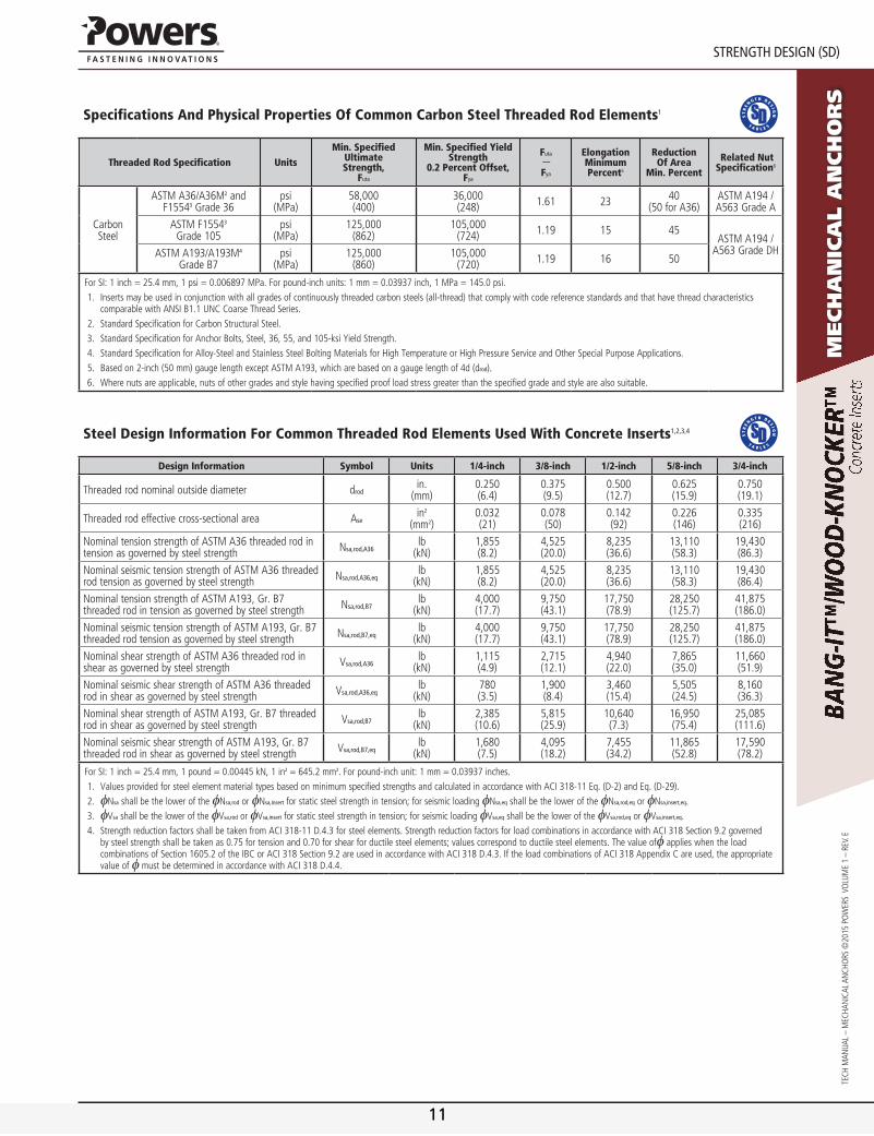
Specifications And Physical Properties Of Common Carbon Steel Threaded Rod Elements1
Threaded Rod Specification Units
Min. SpecifiedUltimateStrength,
Futa
Min. Specified Yield Strength
0.2 Percent Offset, Fya
Futa
-Fya
ElongationMinimum Percent5
Reduction Of Area
Min. Percent
Related NutSpecification6
Carbonsteel
AsTM A36/A36M2 andF15543 Grade 36
psi(MPa)
58,000(400)
36,000(248) 1.61 23 40
(50 for A36)AsTM A194 / A563 Grade A
AsTM F15543
Grade 105psi
(MPa)125,000
(862)105,000
(724) 1.19 15 45AsTM A194 /
A563 Grade DHAsTM A193/A193M4
Grade B7psi
(MPa)125,000
(860)105,000
(720) 1.19 16 50
ForSI:1inch=25.4mm,1psi=0.006897MPa.Forpound-inchunits:1mm=0.03937inch,1MPa=145.0psi.1. Insertsmaybeusedinconjunctionwithallgradesofcontinuouslythreadedcarbonsteels(all-thread)thatcomplywithcodereferencestandardsandthathavethreadcharacteristics
comparablewithANSIB1.1UNCCoarseThreadSeries.2. StandardSpecificationforCarbonStructuralSteel.3. StandardSpecificationforAnchorBolts,Steel,36,55,and105-ksiYieldStrength.4. StandardSpecificationforAlloy-SteelandStainlessSteelBoltingMaterialsforHighTemperatureorHighPressureServiceandOtherSpecialPurposeApplications.5. Basedon2-inch(50mm)gaugelengthexceptASTMA193,whicharebasedonagaugelengthof4d(drod).6. Wherenutsareapplicable,nutsofothergradesandstylehavingspecifiedproofloadstressgreaterthanthespecifiedgradeandstylearealsosuitable.
Steel Design Information For Common Threaded Rod Elements Used With Concrete Inserts1,2,3,4
Design Information Symbol Units 1/4-inch 3/8-inch 1/2-inch 5/8-inch 3/4-inch
Threaded rod nominal outside diameter drodin.
(mm)0.250(6.4)
0.375(9.5)
0.500(12.7)
0.625(15.9)
0.750(19.1)
Threaded rod effective cross-sectional area Asein2
(mm2)0.032(21)
0.078(50)
0.142(92)
0.226(146)
0.335(216)
Nominal tension strength of AsTM A36 threaded rod in tension as governed by steel strength Nsa,rod,a36
lb(kN)
1,855(8.2)
4,525(20.0)
8,235(36.6)
13,110(58.3)
19,430(86.3)
Nominal seismic tension strength of AsTM A36 threaded rod tension as governed by steel strength Nsa,rod,a36,eq
lb(kN)
1,855(8.2)
4,525(20.0)
8,235(36.6)
13,110(58.3)
19,430(86.4)
Nominal tension strength of AsTM A193, Gr. B7 threaded rod in tension as governed by steel strength Nsa,rod,B7
lb(kN)
4,000(17.7)
9,750(43.1)
17,750(78.9)
28,250(125.7)
41,875(186.0)
Nominal seismic tension strength of AsTM A193, Gr. B7 threaded rod tension as governed by steel strength Nsa,rod,B7,eq
lb(kN)
4,000(17.7)
9,750(43.1)
17,750(78.9)
28,250(125.7)
41,875(186.0)
Nominal shear strength of AsTM A36 threaded rod in shear as governed by steel strength Vsa,rod,a36
lb(kN)
1,115(4.9)
2,715(12.1)
4,940(22.0)
7,865(35.0)
11,660(51.9)
Nominal seismic shear strength of AsTM A36 threaded rod in shear as governed by steel strength Vsa,rod,a36,eq
lb(kN)
780(3.5)
1,900(8.4)
3,460(15.4)
5,505(24.5)
8,160(36.3)
Nominal shear strength of AsTM A193, Gr. B7 threaded rod in shear as governed by steel strength Vsa,rod,B7
lb(kN)
2,385(10.6)
5,815(25.9)
10,640(7.3)
16,950(75.4)
25,085(111.6)
Nominal seismic shear strength of AsTM A193, Gr. B7 threaded rod in shear as governed by steel strength Vsa,rod,B7,eq
lb(kN)
1,680(7.5)
4,095(18.2)
7,455(34.2)
11,865(52.8)
17,590(78.2)
ForSI:1inch=25.4mm,1pound=0.00445kN,1in2=645.2mm2.Forpound-inchunit:1mm=0.03937inches.1. ValuesprovidedforsteelelementmaterialtypesbasedonminimumspecifiedstrengthsandcalculatedinaccordancewithACI318-11Eq.(D-2)andEq.(D-29).2. φNsashallbetheloweroftheφNsa,rodorφNsa,insertforstaticsteelstrengthintension;forseismicloadingφNsa,eqshallbetheloweroftheφNsa,rod,eqorφNsa,insert,eq.3. φVsashallbetheloweroftheφVsa,rodorφVsa,insertforstaticsteelstrengthintension;forseismicloadingφVsa,eqshallbetheloweroftheφVsa,rod,eqorφVsa,insert,eq.4. StrengthreductionfactorsshallbetakenfromACI318-11D.4.3forsteelelements.StrengthreductionfactorsforloadcombinationsinaccordancewithACI318Section9.2governed
bysteelstrengthshallbetakenas0.75fortensionand0.70forshearforductilesteelelements;valuescorrespondtoductilesteelelements.ThevalueofφapplieswhentheloadcombinationsofSection1605.2oftheIBCorACI318Section9.2areusedinaccordancewithACI318D.4.3.IftheloadcombinationsofACI318AppendixCareused,theappropriatevalueofφmustbedeterminedinaccordancewithACI318D.4.4.
11
www.powers.com 9
TECH MAN
UAL – MECHAN
iCAL ANCHo
rs ©2015 Po
WErs Vo
LUME 1 – rEV. E
StrenGth DeSIGn (SD)
Mech
an
ica
l a
nch
or
s
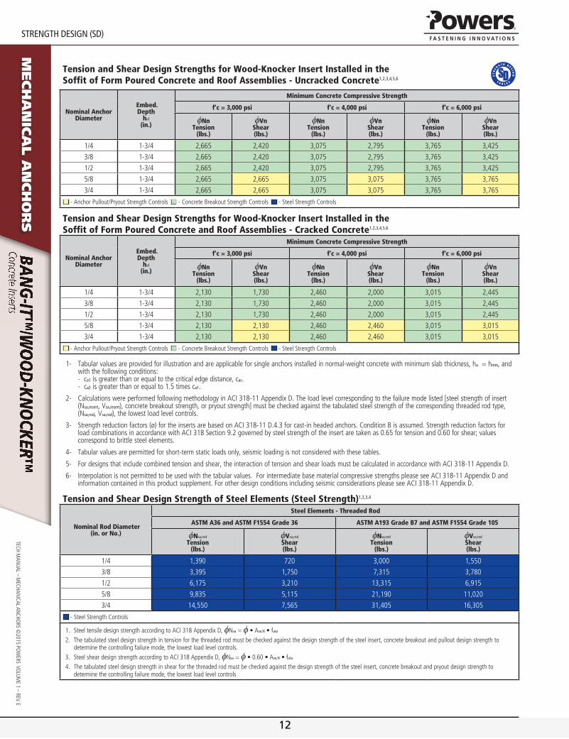
Tension and Shear Design Strengths for Wood-Knocker Insert Installed in the Soffit of Form Poured Concrete and Roof Assemblies - Uncracked Concrete1,2,3,4,5,6
Nominal Anchor Diameter
Embed.Depth
hef
(in.)
Minimum Concrete Compressive Strength
f'c = 3,000 psi f'c = 4,000 psi f'c = 6,000 psi
φNnTension
(lbs.)
φVnShear(lbs.)
φNnTension
(lbs.)
φVnShear(lbs.)
φNnTension
(lbs.)
φVnShear(lbs.)
1/4 1-3/4 2,665 2,420 3,075 2,795 3,765 3,425
3/8 1-3/4 2,665 2,420 3,075 2,795 3,765 3,425
1/2 1-3/4 2,665 2,420 3,075 2,795 3,765 3,425
5/8 1-3/4 2,665 2,665 3,075 3,075 3,765 3,765
3/4 1-3/4 2,665 2,665 3,075 3,075 3,765 3,765
■ -AnchorPullout/PryoutStrengthControls■ -ConcreteBreakoutStrengthControls■ -SteelStrengthControls
Tension and Shear Design Strengths for Wood-Knocker Insert Installed in the Soffit of Form Poured Concrete and Roof Assemblies - Cracked Concrete1,2,3,4,5,6
Nominal Anchor Diameter
Embed.Depth
hef
(in.)
Minimum Concrete Compressive Strength
f'c = 3,000 psi f'c = 4,000 psi f'c = 6,000 psi
φNnTension
(lbs.)
φVnShear(lbs.)
φNnTension
(lbs.)
φVnShear(lbs.)
φNnTension
(lbs.)
φVnShear(lbs.)
1/4 1-3/4 2,130 1,730 2,460 2,000 3,015 2,445
3/8 1-3/4 2,130 1,730 2,460 2,000 3,015 2,445
1/2 1-3/4 2,130 1,730 2,460 2,000 3,015 2,445
5/8 1-3/4 2,130 2,130 2,460 2,460 3,015 3,015
3/4 1-3/4 2,130 2,130 2,460 2,460 3,015 3,015
■ -AnchorPullout/PryoutStrengthControls■ -ConcreteBreakoutStrengthControls■ -SteelStrengthControls
1- Tabular values are provided for illustration and are applicable for single anchors installed in normal-weight concrete with minimum slab thickness, ha = hmin, and with the following conditions: - ca1 is greater than or equal to the critical edge distance, cac. - ca2 is greater than or equal to 1.5 times ca1.
2- Calculations were performed following methodology in ACi 318-11 Appendix D. The load level corresponding to the failure mode listed [steel strength of insert (Nsa,insert, Vsa,insert), concrete breakout strength, or pryout strength] must be checked against the tabulated steel strength of the corresponding threaded rod type, (Nsa,rod, Vsa,rod), the lowest load level controls.
3- strength reduction factors (ø) for the inserts are based on ACi 318-11 D.4.3 for cast-in headed anchors. Condition B is assumed. strength reduction factors for load combinations in accordance with ACi 318 section 9.2 governed by steel strength of the insert are taken as 0.65 for tension and 0.60 for shear; values correspond to brittle steel elements.
4- Tabular values are permitted for short-term static loads only, seismic loading is not considered with these tables.
5- For designs that include combined tension and shear, the interaction of tension and shear loads must be calculated in accordance with ACi 318-11 Appendix D.
6- interpolation is not permitted to be used with the tabular values. For intermediate base material compressive strengths please see ACi 318-11 Appendix D and information contained in this product supplement. For other design conditions including seismic considerations please see ACi 318-11 Appendix D.
Tension and Shear Design Strength of Steel Elements (Steel Strength)1,2,3,4
Nominal Rod Diameter(in. or No.)
Steel Elements - Threaded Rod
ASTM A36 and ASTM F1554 Grade 36 ASTM A193 Grade B7 and ASTM F1554 Grade 105
φNsa,rod
Tension(lbs.)
φVsa,rod
Shear(lbs.)
φNsa,rod
Tension(lbs.)
φVsa,rod
Shear(lbs.)
1/4 1,390 720 3,000 1,550
3/8 3,395 1,750 7,315 3,780
1/2 6,175 3,210 13,315 6,915
5/8 9,835 5,115 21,190 11,020
3/4 14,550 7,565 31,405 16,305
■ -SteelStrengthControls
1. SteeltensiledesignstrengthaccordingtoACI318AppendixD,φNsa=φ•Ase,n•futa
2. Thetabulatedsteeldesignstrengthintensionforthethreadedrodmustbecheckedagainstthedesignstrengthofthesteelinsert,concretebreakoutandpulloutdesignstrengthtodeterminethecontrollingfailuremode,thelowestloadlevelcontrols.
3. SteelsheardesignstrengthaccordingtoACI318AppendixD,φNsa=φ•0.60•Ase,n•futa
4. Thetabulatedsteeldesignstrengthinshearforthethreadedrodmustbecheckedagainstthedesignstrengthofthesteelinsert,concretebreakoutandpryoutdesignstrengthtodeterminethecontrollingfailuremode,thelowestloadlevelcontrols
12
www.powers.com 10
StrenGth DeSIGn (SD)
TECH
MAN
UAL
– M
ECHA
NiC
AL A
NCH
ors
©20
15 P
oW
Ers
Vo
LUM
E 1
– rE
V. E
Mech
an
ica
l a
nch
or
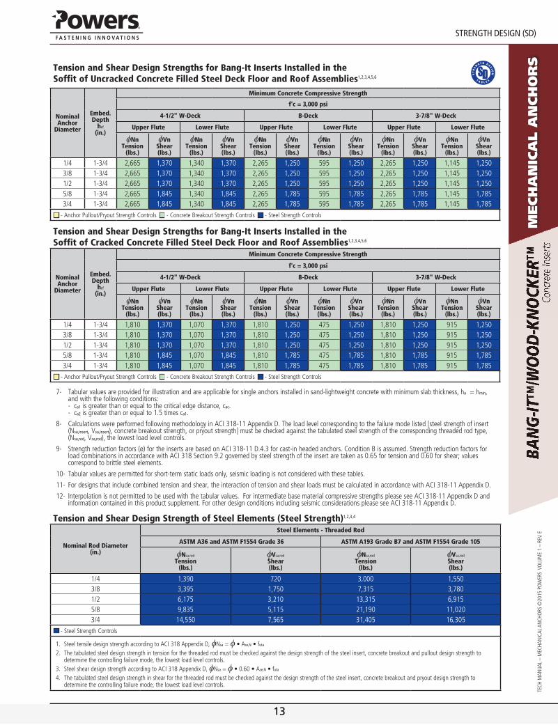
sTension and Shear Design Strengths for Bang-It Inserts Installed in the Soffit of Uncracked Concrete Filled Steel Deck Floor and Roof Assemblies1,2,3,4,5,6
Nominal Anchor
Diameter
Embed.Depth
hef
(in.)
Minimum Concrete Compressive Strength
f'c = 3,000 psi
4-1/2" W-Deck B-Deck 3-7/8" W-Deck
Upper Flute Lower Flute Upper Flute Lower Flute Upper Flute Lower Flute
φNnTension
(lbs.)
φVnShear(lbs.)
φNnTension
(lbs.)
φVnShear(lbs.)
φNnTension
(lbs.)
φVnShear(lbs.)
φNnTension
(lbs.)
φVnShear(lbs.)
φNnTension
(lbs.)
φVnShear(lbs.)
φNnTension
(lbs.)
φVnShear(lbs.)
1/4 1-3/4 2,665 1,370 1,340 1,370 2,265 1,250 595 1,250 2,265 1,250 1,145 1,2503/8 1-3/4 2,665 1,370 1,340 1,370 2,265 1,250 595 1,250 2,265 1,250 1,145 1,2501/2 1-3/4 2,665 1,370 1,340 1,370 2,265 1,250 595 1,250 2,265 1,250 1,145 1,2505/8 1-3/4 2,665 1,845 1,340 1,845 2,265 1,785 595 1,785 2,265 1,785 1,145 1,7853/4 1-3/4 2,665 1,845 1,340 1,845 2,265 1,785 595 1,785 2,265 1,785 1,145 1,785
■ -AnchorPullout/PryoutStrengthControls■ -ConcreteBreakoutStrengthControls■ -SteelStrengthControls
Tension and Shear Design Strengths for Bang-It Inserts Installed in the Soffit of Cracked Concrete Filled Steel Deck Floor and Roof Assemblies1,2,3,4,5,6
Nominal Anchor
Diameter
Embed.Depth
hef
(in.)
Minimum Concrete Compressive Strength
f'c = 3,000 psi
4-1/2" W-Deck B-Deck 3-7/8" W-Deck
Upper Flute Lower Flute Upper Flute Lower Flute Upper Flute Lower Flute
φNnTension
(lbs.)
φVnShear(lbs.)
φNnTension
(lbs.)
φVnShear(lbs.)
φNnTension
(lbs.)
φVnShear(lbs.)
φNnTension
(lbs.)
φVnShear(lbs.)
φNnTension
(lbs.)
φVnShear(lbs.)
φNnTension
(lbs.)
φVnShear(lbs.)
1/4 1-3/4 1,810 1,370 1,070 1,370 1,810 1,250 475 1,250 1,810 1,250 915 1,2503/8 1-3/4 1,810 1,370 1,070 1,370 1,810 1,250 475 1,250 1,810 1,250 915 1,2501/2 1-3/4 1,810 1,370 1,070 1,370 1,810 1,250 475 1,250 1,810 1,250 915 1,2505/8 1-3/4 1,810 1,845 1,070 1,845 1,810 1,785 475 1,785 1,810 1,785 915 1,7853/4 1-3/4 1,810 1,845 1,070 1,845 1,810 1,785 475 1,785 1,810 1,785 915 1,785
■ -AnchorPullout/PryoutStrengthControls■ -ConcreteBreakoutStrengthControls■ -SteelStrengthControls
7- Tabular values are provided for illustration and are applicable for single anchors installed in sand-lightweight concrete with minimum slab thickness, ha = hmin, and with the following conditions: - ca1 is greater than or equal to the critical edge distance, cac. - ca2 is greater than or equal to 1.5 times ca1.
8- Calculations were performed following methodology in ACi 318-11 Appendix D. The load level corresponding to the failure mode listed [steel strength of insert (Nsa,insert, Vsa,insert), concrete breakout strength, or pryout strength] must be checked against the tabulated steel strength of the corresponding threaded rod type, (Nsa,rod, Vsa,rod), the lowest load level controls.
9- strength reduction factors (ø) for the inserts are based on ACi 318-11 D.4.3 for cast-in headed anchors. Condition B is assumed. strength reduction factors for load combinations in accordance with ACi 318 section 9.2 governed by steel strength of the insert are taken as 0.65 for tension and 0.60 for shear; values correspond to brittle steel elements.
10- Tabular values are permitted for short-term static loads only, seismic loading is not considered with these tables.
11- For designs that include combined tension and shear, the interaction of tension and shear loads must be calculated in accordance with ACi 318-11 Appendix D.
12- interpolation is not permitted to be used with the tabular values. For intermediate base material compressive strengths please see ACi 318-11 Appendix D and information contained in this product supplement. For other design conditions including seismic considerations please see ACi 318-11 Appendix D.
Tension and Shear Design Strength of Steel Elements (Steel Strength)1,2,3,4
Nominal Rod Diameter(in.)
Steel Elements - Threaded Rod
ASTM A36 and ASTM F1554 Grade 36 ASTM A193 Grade B7 and ASTM F1554 Grade 105
φNsa,rod
Tension(lbs.)
φVsa,rod
Shear(lbs.)
φNsa,rod
Tension(lbs.)
φVsa,rod
Shear(lbs.)
1/4 1,390 720 3,000 1,5503/8 3,395 1,750 7,315 3,7801/2 6,175 3,210 13,315 6,9155/8 9,835 5,115 21,190 11,0203/4 14,550 7,565 31,405 16,305
■ -SteelStrengthControls
1. SteeltensiledesignstrengthaccordingtoACI318AppendixD,φNsa=φ•Ase,n•futa
2. Thetabulatedsteeldesignstrengthintensionforthethreadedrodmustbecheckedagainstthedesignstrengthofthesteelinsert,concretebreakoutandpulloutdesignstrengthtodeterminethecontrollingfailuremode,thelowestloadlevelcontrols.
3. SteelsheardesignstrengthaccordingtoACI318AppendixD,φNsa=φ•0.60•Ase,n•futa
4. Thetabulatedsteeldesignstrengthinshearforthethreadedrodmustbecheckedagainstthedesignstrengthofthesteelinsert,concretebreakoutandpryoutdesignstrengthtodeterminethecontrollingfailuremode,thelowestloadlevelcontrols.
13

www.powers.com 11
TECH MAN
UAL – MECHAN
iCAL ANCHo
rs ©2015 Po
WErs Vo
LUME 1 – rEV. E
orDerInG InformatIon
Mech
an
ica
l a
nch
or
s
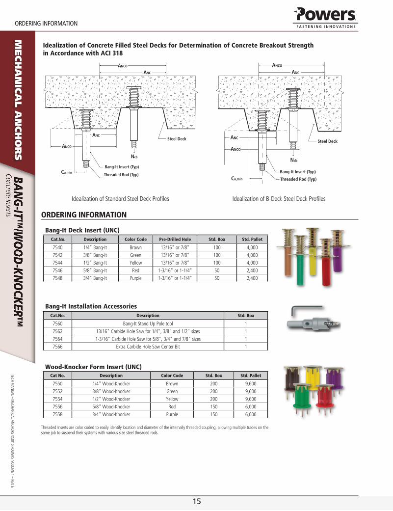
Idealization of Concrete Filled Steel Decks for Determination of Concrete Breakout Strength in Accordance with ACI 318
Steel Deck
Bang-It Insert (Typ)
Threaded Rod (Typ)Ca,min
Ncb
ANCO
ANCO
ANC
ANC
Steel Deck
Bang-It Insert (Typ)
Threaded Rod (Typ)
Ncb
ANCO
ANC
ANCO
Ca,min
ANC
idealization of standard steel Deck Profiles idealization of B-Deck steel Deck Profiles
ordering inforMAtion
Bang-It Deck Insert (UNC) Cat.No. Description Color Code Pre-Drilled Hole Std. Box Std. Pallet
7540 1/4” Bang-it Brown 13/16" or 7/8" 100 4,000
7542 3/8” Bang-it Green 13/16" or 7/8" 100 4,000
7544 1/2” Bang-it Yellow 13/16" or 7/8" 100 4,000
7546 5/8” Bang-it red 1-3/16" or 1-1/4" 50 2,400
7548 3/4” Bang-it Purple 1-3/16" or 1-1/4" 50 2,400
Bang-It Installation AccessoriesCat.No. Description Std. Box
7560 Bang-it stand Up Pole tool 1
7562 13/16" Carbide Hole saw for 1/4", 3/8" and 1/2" sizes 1
7564 1-3/16" Carbide Hole saw for 5/8", 3/4" and 7/8" sizes 1
7566 Extra Carbide Hole saw Center Bit 1
Wood-Knocker Form Insert (UNC)Cat No. Description Color Code Std. Box Std. Pallet
7550 1/4" Wood-Knocker Brown 200 9,600
7552 3/8" Wood-Knocker Green 200 9,600
7554 1/2" Wood-Knocker Yellow 200 9,600
7556 5/8" Wood-Knocker red 150 6,000
7558 3/4" Wood-Knocker Purple 150 6,000
ThreadedInsertsarecolorcodedtoeasilyidentifylocationanddiameteroftheinternallythreadedcoupling,allowingmultipletradesonthesamejobtosuspendtheirsystemswithvarioussizesteelthreadedrods.
14
www.powers.com 11
TECH MAN
UAL – MECHAN
iCAL ANCHo
rs ©2015 Po
WErs Vo
LUME 1 – rEV. E
orDerInG InformatIon
Mech
an
ica
l a
nch
or
s
Idealization of Concrete Filled Steel Decks for Determination of Concrete Breakout Strength in Accordance with ACI 318
Steel Deck
Bang-It Insert (Typ)
Threaded Rod (Typ)Ca,min
Ncb
ANCO
ANCO
ANC
ANC
Steel Deck
Bang-It Insert (Typ)
Threaded Rod (Typ)
Ncb
ANCO
ANC
ANCO
Ca,min
ANC
idealization of standard steel Deck Profiles idealization of B-Deck steel Deck Profiles
ordering inforMAtion
Bang-It Deck Insert (UNC) Cat.No. Description Color Code Pre-Drilled Hole Std. Box Std. Pallet
7540 1/4” Bang-it Brown 13/16" or 7/8" 100 4,000
7542 3/8” Bang-it Green 13/16" or 7/8" 100 4,000
7544 1/2” Bang-it Yellow 13/16" or 7/8" 100 4,000
7546 5/8” Bang-it red 1-3/16" or 1-1/4" 50 2,400
7548 3/4” Bang-it Purple 1-3/16" or 1-1/4" 50 2,400
Bang-It Installation AccessoriesCat.No. Description Std. Box
7560 Bang-it stand Up Pole tool 1
7562 13/16" Carbide Hole saw for 1/4", 3/8" and 1/2" sizes 1
7564 1-3/16" Carbide Hole saw for 5/8", 3/4" and 7/8" sizes 1
7566 Extra Carbide Hole saw Center Bit 1
Wood-Knocker Form Insert (UNC)Cat No. Description Color Code Std. Box Std. Pallet
7550 1/4" Wood-Knocker Brown 200 9,600
7552 3/8" Wood-Knocker Green 200 9,600
7554 1/2" Wood-Knocker Yellow 200 9,600
7556 5/8" Wood-Knocker red 150 6,000
7558 3/4" Wood-Knocker Purple 150 6,000
ThreadedInsertsarecolorcodedtoeasilyidentifylocationanddiameteroftheinternallythreadedcoupling,allowingmultipletradesonthesamejobtosuspendtheirsystemswithvarioussizesteelthreadedrods.
15
ICC-ES Evaluation Reports are not to be construed as representing aesthetics or any other attributes not specifically addressed, nor are they to be construed as an endorsement of the subject of the report or a recommendation for its use. There is no warranty by ICC Evaluation Service, LLC, express or implied, as to any finding or other matter in this report, or as to any product covered by the report.
Copyright © 2015 Page 1 of 12 1000
ICC-ES Evaluation Report ESR-3657 Issued December 2014 This report is subject to renewal December 2015.
www.icc-es.org | (800) 423-6587 | (562) 699-0543 A Subsidiary of the International Code Council ®
DIVISION: 03 00 00—CONCRETE Section: 03 15 19—Cast-In Concrete Anchors Section: 03 16 00—Concrete Anchors REPORT HOLDER: POWERS FASTENERS, INC. 701 EAST JOPPA ROAD TOWSON, MARYLAND 21286 (914) 235-6300 or (800) 524-3244 www.powers.com [email protected] EVALUATION SUBJECT: POWERS WOOD-KNOCKERTM CONCRETE INSERTS AND BANG-ITTM CONCRETE INSERTS FOR STEEL DECK IN CRACKED AND UNCRACKED CONCRETE 1.0 EVALUATION SCOPE
Compliance with the following codes:
2012, 2009, and 2006 International Building Code® (IBC)
2012, 2009, and 2006 International Residential Code® (IRC)
Properties evaluated:
Structural
2.0 USES
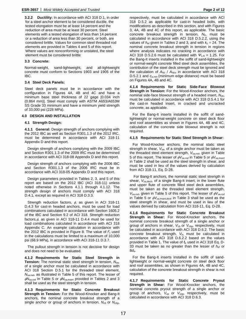
The Powers Wood-Knocker concrete inserts are used to resist static, wind, and seismic tension and shear loads in cracked and uncracked normal-weight concrete, sand-lightweight, and all-lightweight concrete having a specified compressive strength, f′c, of 2,500 psi to 10,000 psi (17.2 MPa to 68.9 MPa).
The Powers Bang-It steel deck concrete inserts are used to resist static, wind, and seismic tension and shear loads in the soffit of cracked and uncracked normal-weight concrete and sand-lightweight concrete on steel deck having a specified compressive strength, f′c, of 2,500 psi to 10,000 psi (17.2 MPa to 68.9 MPa).
There are seven models for the Wood-Knocker inserts; five fractional and two metric: 1/4-inch, 3/8-inch, M10, M12, 1/2-inch, 5/8-inch, and 3/4-inch, corresponding to the sizes of the threaded rods or bolts used for the inserts.
There are seven models for the Bang-It inserts; five fractional and two metric: 1/4-inch, 3/8-inch, M10, M12, 1/2-inch, 5/8-inch, and 3/4-inch, corresponding to the sizes of the threaded rods or bolts used for the inserts.
Reference to “inserts” in this report refers to the
manufactured specialty anchorage products (Wood-Knockers and Bang-Its) used in concrete; reference to “steel elements” refers to threaded rods or bolts; reference to “anchors” in this report refers to the installed inserts in concrete with threaded rods or bolts.
The inserts are alternatives to cast-in anchors described in Sections 1908 and 1909 of the 2012 IBC and Sections 1911 and 1912 of the 2009 and 2006 IBC. The anchors may be used where an engineered design is submitted in accordance with Section R301.1.3 of the IRC.
3.0 DESCRIPTION
3.1 Wood-Knocker and Bang-It Inserts:
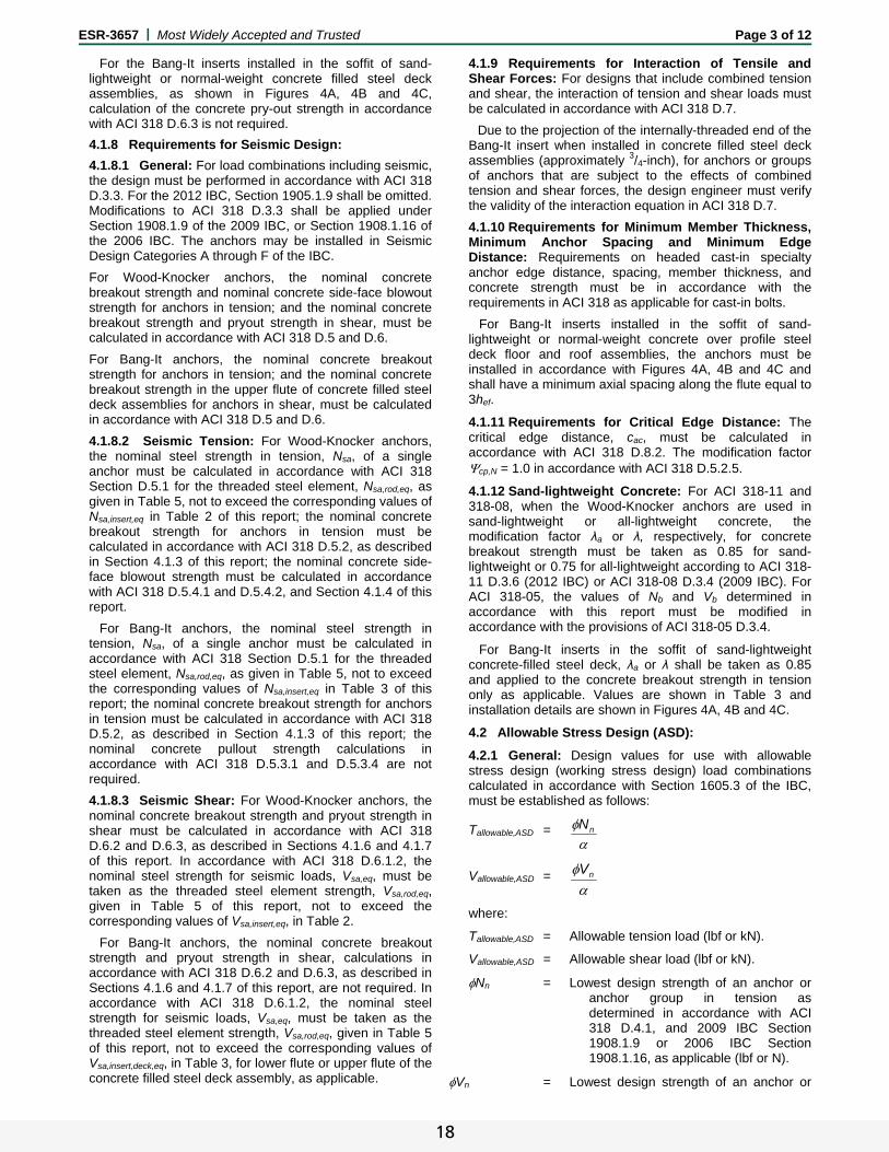
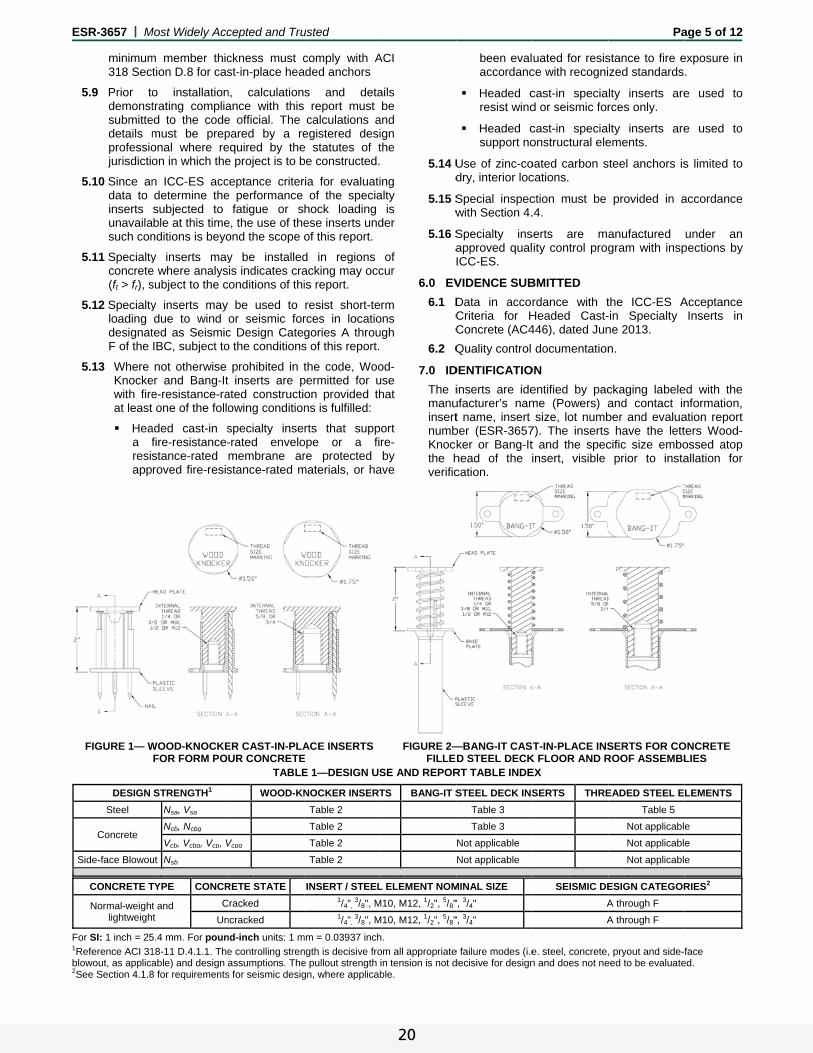
The Wood-Knocker inserts are cast-in concrete form inserts. The insert consists of a steel internally threaded headed insert (body), an outer plastic sleeve and nails used to attach the insert to the inside surface of concrete formwork. The insert is illustrated in Figure 1 and Figure 6. The internally threaded inserts are manufactured from low carbon steel. The Wood-Knocker inserts have minimum 5 μm (0.002-inch) zinc plating. The plastic sleeve is fabricated from polypropylene.
The Bang-It steel deck inserts are cast-in concrete inserts. The insert consists of a steel internally threaded headed insert (body), an outer spring, a plastic sleeve and a washer (base plate). The insert is illustrated in Figure 2 and Figure 6. The internally threaded insert and washer are manufactured from low carbon steel. The Bang-It inserts have a minimum 5 μm (0.002-inch) zinc plating. The spring is manufactured from steel music wire. The plastic sleeve is fabricated from polypropylene.
The anchor assembly is comprised of a Wood-Knocker or Bang-It insert with a threaded steel element (e.g. rod or bolt). The Wood-Knocker insert is installed on the inside surface of wood formwork and the nails driven into the form until the insert base sits flush on the form. The Bang-It insert is installed in a predrilled hole in the topside of the metal deck, and impacted with sufficient force to compress the spring and drive the flared plastic fins of the sleeve completely through the hole. Concrete can then be cast over the insert.
3.2 Steel Elements:
3.2.1 Threaded Steel Rods and Bolts: Threaded steel rods (all-thread) or bolts must be threaded on their embedded end in diameters as described in Table 5 of this report. Specifications for grades of common threaded rod or bolts, including the mechanical strength properties are described in Table 4 of this report. Carbon steel threaded rods or bolts must be furnished with a minimum 0.0002-inch-thick (0.005 mm) zinc plating.
16
ESR-3657 | Most Widely Accepted and Trusted Page 2 of 12
3.2.2 Ductility: In accordance with ACI 318 D.1, in order for a steel anchor element to be considered ductile, the tested elongation must be at least 14 percent and the reduction of area must be at least 30 percent. Steel elements with a tested elongation of less than 14 percent or a reduction of area less than 30 percent, or both, are considered brittle. Values for common steel threaded rod elements are provided in Tables 4 and 5 of this report. Where values are nonconforming or unstated, the steel element must be considered brittle 3.3 Concrete:
Normal-weight, sand-lightweight, and all-lightweight concrete must conform to Sections 1903 and 1905 of the IBC.
3.4 Steel Deck Panels:
Steel deck panels must be in accordance with the configuration in Figures 4A, 4B and 4C and have a minimum base steel thickness of 22 gage [0.034 inch (0.864 mm)]. Steel must comply with ASTM A653/A653M SS Grade 33 minimum and have a minimum yield strength of 33,000 psi (228 MPa).
4.0 DESIGN AND INSTALLATION
4.1 Strength Design:
4.1.1 General: Design strength of anchors complying with the 2012 IBC as well as Section R301.1.3 of the 2012 IRC, must be determined in accordance with ACI 318-11 Appendix D and this report.
Design strength of anchors complying with the 2009 IBC and Section R301.1.3 of the 2009 IRC must be determined in accordance with ACI 318-08 Appendix D and this report.
Design strength of anchors complying with the 2006 IBC and Section R301.1.3 of the 2006 IRC must be in accordance with ACI 318-05 Appendix D and this report.
Design parameters provided in Tables 2, 3, and 5 of this report are based on the 2012 IBC (ACI 318-11) unless noted otherwise in Sections 4.1.1 through 4.1.12. The strength design of anchors must comply with ACI 318 D.4.1, except as required in ACI 318 D.3.3.
Strength reduction factors, , as given in ACI 318-11 D.4.3 for cast-in headed anchors, must be used for load combinations calculated in accordance with Section 1605.2 of the IBC and Section 9.2 of ACI 318. Strength reduction factors,, as given in ACI 318-11 D.4.4 must be used for load combinations calculated in accordance with ACI 318 Appendix C. An example calculation in accordance with the 2012 IBC is provided in Figure 8. The value of f′c used in the calculations must be limited to a maximum of 10,000 psi (68.9 MPa), in accordance with ACI 318-11 D.3.7.
The pullout strength in tension is not decisive for design and does not need to be evaluated.
4.1.2 Requirements for Static Steel Strength in Tension: The nominal static steel strength in tension, Nsa, of a single anchor must be calculated in accordance with ACI 318 Section D.5.1 for the threaded steel element, Nsa,rod, as illustrated in Table 5 of this report. The lesser of Nsa,rod in Table 5 or Nsa,insert provided in Tables 2 and 3 shall be used as the steel strength in tension.
4.1.3 Requirements for Static Concrete Breakout Strength in Tension: For the Wood-Knocker and Bang-It anchors, the nominal concrete breakout strength of a single anchor or group of anchors in tension, Ncb or Ncbg,
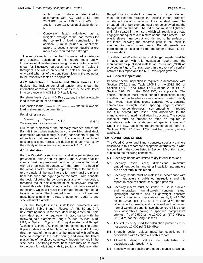
respectively, must be calculated in accordance with ACI 318 D.5.2 as applicable for cast-in headed bolts, with modifications as described in this section, and with Figures 3, 4A, 4B and 4C of this report, as applicable. The basic concrete breakout strength in tension, Nb, must be calculated in accordance with ACI 318 D.5.2.2, using the values of hef given in Tables 2 and 3, and with kc = 24. The nominal concrete breakout strength in tension in regions where analysis indicates no cracking in accordance with ACI 318 D.5.2.6 must be calculated with Ψc,N = 1.25. For the Bang-It inserts installed in the soffit of sand-lightweight or normal-weight concrete filled steel deck assemblies, the contribution of the steel deck strength must be ignored and the calculation of ANc / ANco in accordance with ACI 318 D.5.2.1 and ca,min (minimum edge distance) must be based on Figures 4A, 4B and 4C. 4.1.4 Requirements for Static Side-Face Blowout Strength in Tension: For the Wood-Knocker anchors, the nominal side-face blowout strength of a headed insert, Nsb, must be calculated in accordance with ACI 318 D.5.4.1 for the cast-in headed insert, in cracked and uncracked concrete, as applicable.
For the Bang-It inserts installed in the soffit of sand-lightweight or normal-weight concrete on steel deck floor and roof assemblies as shown in Figures 4A, 4B and 4C, calculation of the concrete side blowout strength is not required.
4.1.5 Requirements for Static Steel Strength in Shear:
For Wood-Knocker anchors, the nominal static steel strength in shear, Vsa, of a single anchor must be taken as the threaded steel element strength, Vsa,rod, given in Table 5 of this report. The lesser of Vsa,rod in Table 5 or Vsa,insert in Table 2 shall be used as the steel strength in shear, and must be used in lieu of the values derived by calculation from ACI 318-11, Eq. D-28.
For Bang-It anchors, the nominal static steel strength in shear, Vsa,deck, of a single Bang-It insert, in the lower flute and upper flute of concrete filled steel deck assemblies, must be taken as the threaded steel element strength, Vsa,rod, given in Table 5 of this report. The lesser of Vsa,rod in Table 5 or Vsa,insert,deck in Table 3 shall be used as the steel strength in shear, and must be used in lieu of the values derived by calculation from ACI 318-11, Eq. D-28.
4.1.6 Requirements for Static Concrete Breakout Strength in Shear: For Wood-Knocker anchors, the nominal concrete breakout strength of a single anchor or group of anchors in shear, Vcb or Vcbg, respectively, must be calculated in accordance with ACI 318 D.6.2. The basic concrete breakout strength, Vb, must be calculated in accordance with ACI 318 D.6.2.2 based on the values provided in Table 1. The value of ℓe used in ACI 318 Eq. D-33 must be taken as no greater than the lesser of hef or 8da.
For the Bang-It inserts installed in the soffit of sand-lightweight or normal-weight concrete on steel deck floor and roof assemblies, as shown in Figures 4A, 4B and 4C, calculation of the concrete breakout strength in shear is not required.
4.1.7 Requirements for Static Concrete Pryout Strength in Shear: For Wood-Knocker anchors, the nominal concrete pryout strength of a single anchor or group of anchors, Vcp or Vcpg, respectively, must be calculated in accordance with ACI 318 D.6.3.
17
ESR-3657 | Most Widely Accepted and Trusted Page 3 of 12
For the Bang-It inserts installed in the soffit of sand-lightweight or normal-weight concrete filled steel deck assemblies, as shown in Figures 4A, 4B and 4C, calculation of the concrete pry-out strength in accordance with ACI 318 D.6.3 is not required.
4.1.8 Requirements for Seismic Design:
4.1.8.1 General: For load combinations including seismic, the design must be performed in accordance with ACI 318 D.3.3. For the 2012 IBC, Section 1905.1.9 shall be omitted. Modifications to ACI 318 D.3.3 shall be applied under Section 1908.1.9 of the 2009 IBC, or Section 1908.1.16 of the 2006 IBC. The anchors may be installed in Seismic Design Categories A through F of the IBC.
For Wood-Knocker anchors, the nominal concrete breakout strength and nominal concrete side-face blowout strength for anchors in tension; and the nominal concrete breakout strength and pryout strength in shear, must be calculated in accordance with ACI 318 D.5 and D.6.
For Bang-It anchors, the nominal concrete breakout strength for anchors in tension; and the nominal concrete breakout strength in the upper flute of concrete filled steel deck assemblies for anchors in shear, must be calculated in accordance with ACI 318 D.5 and D.6.
4.1.8.2 Seismic Tension: For Wood-Knocker anchors, the nominal steel strength in tension, Nsa, of a single anchor must be calculated in accordance with ACI 318 Section D.5.1 for the threaded steel element, Nsa,rod,eq, as given in Table 5, not to exceed the corresponding values of Nsa,insert,eq in Table 2 of this report; the nominal concrete breakout strength for anchors in tension must be calculated in accordance with ACI 318 D.5.2, as described in Section 4.1.3 of this report; the nominal concrete side-face blowout strength must be calculated in accordance with ACI 318 D.5.4.1 and D.5.4.2, and Section 4.1.4 of this report.
For Bang-It anchors, the nominal steel strength in tension, Nsa, of a single anchor must be calculated in accordance with ACI 318 Section D.5.1 for the threaded steel element, Nsa,rod,eq, as given in Table 5, not to exceed the corresponding values of Nsa,insert,eq in Table 3 of this report; the nominal concrete breakout strength for anchors in tension must be calculated in accordance with ACI 318 D.5.2, as described in Section 4.1.3 of this report; the nominal concrete pullout strength calculations in accordance with ACI 318 D.5.3.1 and D.5.3.4 are not required.
4.1.8.3 Seismic Shear: For Wood-Knocker anchors, the nominal concrete breakout strength and pryout strength in shear must be calculated in accordance with ACI 318 D.6.2 and D.6.3, as described in Sections 4.1.6 and 4.1.7 of this report. In accordance with ACI 318 D.6.1.2, the nominal steel strength for seismic loads, Vsa,eq, must be taken as the threaded steel element strength, Vsa,rod,eq, given in Table 5 of this report, not to exceed the corresponding values of Vsa,insert,eq, in Table 2.
For Bang-It anchors, the nominal concrete breakout strength and pryout strength in shear, calculations in accordance with ACI 318 D.6.2 and D.6.3, as described in Sections 4.1.6 and 4.1.7 of this report, are not required. In accordance with ACI 318 D.6.1.2, the nominal steel strength for seismic loads, Vsa,eq, must be taken as the threaded steel element strength, Vsa,rod,eq, given in Table 5 of this report, not to exceed the corresponding values of Vsa,insert,deck,eq, in Table 3, for lower flute or upper flute of the concrete filled steel deck assembly, as applicable.
4.1.9 Requirements for Interaction of Tensile and Shear Forces: For designs that include combined tension and shear, the interaction of tension and shear loads must be calculated in accordance with ACI 318 D.7.
Due to the projection of the internally-threaded end of the Bang-It insert when installed in concrete filled steel deck assemblies (approximately 3/4-inch), for anchors or groups of anchors that are subject to the effects of combined tension and shear forces, the design engineer must verify the validity of the interaction equation in ACI 318 D.7.
4.1.10 Requirements for Minimum Member Thickness, Minimum Anchor Spacing and Minimum Edge Distance: Requirements on headed cast-in specialty anchor edge distance, spacing, member thickness, and concrete strength must be in accordance with the requirements in ACI 318 as applicable for cast-in bolts.
For Bang-It inserts installed in the soffit of sand-lightweight or normal-weight concrete over profile steel deck floor and roof assemblies, the anchors must be installed in accordance with Figures 4A, 4B and 4C and shall have a minimum axial spacing along the flute equal to 3hef.
4.1.11 Requirements for Critical Edge Distance: The critical edge distance, cac, must be calculated in accordance with ACI 318 D.8.2. The modification factor cp,N = 1.0 in accordance with ACI 318 D.5.2.5. 4.1.12 Sand-lightweight Concrete: For ACI 318-11 and 318-08, when the Wood-Knocker anchors are used in sand-lightweight or all-lightweight concrete, the modification factor λa or λ, respectively, for concrete breakout strength must be taken as 0.85 for sand-lightweight or 0.75 for all-lightweight according to ACI 318-11 D.3.6 (2012 IBC) or ACI 318-08 D.3.4 (2009 IBC). For ACI 318-05, the values of Nb and Vb determined in accordance with this report must be modified in accordance with the provisions of ACI 318-05 D.3.4.
For Bang-It inserts in the soffit of sand-lightweight concrete-filled steel deck, λa or λ shall be taken as 0.85 and applied to the concrete breakout strength in tension only as applicable. Values are shown in Table 3 and installation details are shown in Figures 4A, 4B and 4C.
4.2 Allowable Stress Design (ASD):
4.2.1 General: Design values for use with allowable stress design (working stress design) load combinations calculated in accordance with Section 1605.3 of the IBC, must be established as follows:
Tallowable,ASD = nN
Vallowable,ASD = nV
where:
Tallowable,ASD = Allowable tension load (lbf or kN).
Vallowable,ASD = Allowable shear load (lbf or kN).
Nn = Lowest design strength of an anchor or anchor group in tension as determined in accordance with ACI 318 D.4.1, and 2009 IBC Section 1908.1.9 or 2006 IBC Section 1908.1.16, as applicable (lbf or N).
Vn = Lowest design strength of an anchor or
18
ESR-3657 | Most Widely Accepted and Trusted Page 4 of 12
anchor group in shear as determined in accordance with ACI 318 D.4.1, and 2009 IBC Section 1908.1.9 or 2006 IBC Section 1908.1.16, as applicable (lbf or N).
α = Conversion factor calculated as a weighted average of the load factors for the controlling load combination. In addition, α must include all applicable factors to account for non-ductile failure modes and required over-strength.
The requirements for member thickness, edge distance and spacing, described in this report, must apply. Examples of allowable stress design values for tension and shear for illustrative purposes are shown in Tables 6 through 9. The values presented in Tables 6 through 9 are only valid when all of the conditions given in the footnotes to the respective tables are applicable.
4.2.2 Interaction of Tensile and Shear Forces: For designs that include combined tension and shear, the interaction of tension and shear loads must be calculated in accordance with ACI 318 D.7 as follows:
For shear loads Vapplied ≤ 0.2Vallowable,ASD, the full allowable load in tension must be permitted.
For tension loads Tapplied ≤ 0.2Tallowable,ASD, the full allowable load in shear must be permitted.
For all other cases:
,+
,≤1.2 (Eq-1)
Due to the projection of the internally-threaded end of the Bang-It insert when installed in concrete filled steel deck assemblies (approximately 3/4-inch), for anchors or groups of anchors that are subject to the effects of combined tension and shear forces, the design engineer must verify the validity of the interaction equation in ACI 318 D.7
4.3 Installation:
For the Wood-Knocker inserts, installation parameters are provided in Table 2 and in Figures 3 and 7. Wood-Knocker inserts must be positioned on wood or similar formwork with all three nails in contact with the form. The head of the Wood-Knocker must be impacted with sufficient force to drive nails all the way into the formwork until the plastic base sits flush and tight against the form. From beneath the deck, following the concrete pour and form removal, a threaded rod or bolt element must be screwed into the internal threads of the Wood-Knocker until fully seated in the inserts, which will result in a thread engagement equal to one diameter. The threaded steel rod or bolt element must have a minimum thread engagement equal to one steel element diameter.
For the Bang-It inserts, installation parameters are provided in Table 3 and in Figures 4A, 4B, 4C and 7. A hole must be made in the steel deck using a step-drill, hole saw, deck punch or equivalent in accordance with the following hole diameters: Bang-It 1/4-inch, 3/8-inch, M10, M12, or 1/2-inch [13/16-inch (21 mm) diameter] and Bang-It 5/8-inch or 3/4-inch [13/16-inch (30 mm) diameter]. The Bang-It plastic sleeve must be placed in the hole, and following this, the head of the insert must be impacted with sufficient force to compress the outer spring and drive the flared plastic fins of the sleeve completely through the hole in the steel deck. The Bang-It metal base plate may be screwed to the deck for additional stability (optional). Before or after
Bang-It insertion in deck, a threaded rod or bolt element must be inserted through the plastic thread protector nozzle until contact is made with the inner steel barrel. The threaded rod or bolt element must then be screwed into the Bang-It internal threads. The rod or bolt must be tightened until fully seated in the insert, which will result in a thread engagement equal to a minimum of one rod diameter. The plastic sleeve must be cut and trimmed to the surface of the insert following the concrete pour if the insert is intended to resist shear loads. Bang-It inserts are permitted to be installed in either the upper or lower flute of the steel deck.
Installation of Wood-Knocker and Bang-It inserts must be in accordance with this evaluation report and the manufacturer’s published installation instruction (MPII) as provided in Figure 7 of this report. In the event of a conflict between this report and the MPII, this report governs.
4.4 Special Inspection:
Periodic special inspection is required in accordance with Section 1705.1.1 and Table 1705.3 of the 2012 IBC, or Section 1704.15 and Table 1704.4 of the 2009 IBC, or Section 1704.13 of the 2006 IBC, as applicable. The special inspector must make periodic inspections during installation of the headed cast-in specialty inserts to verify insert type, insert dimensions, concrete type, concrete compressive strength, insert spacing, edge distances, concrete member thickness, insert embedment, threaded rod fully seated into insert, and adherence to the manufacturer’s printed installation instructions. The special inspector must be present as often as required in accordance with the “statement of special inspection.” Under the IBC, additional requirements as set forth in Sections 1705, 1706 and 1707 must be observed, where applicable.
5.0 CONDITIONS OF USE
The Wood-Knocker and Bang-It concrete specialty anchors described in this report are acceptable alternatives to what is specified in the codes listed in Section 1.0 of this report, subject to the following conditions:
5.1 Specialty inserts are limited to dry interior locations.
5.2 Specialty insert sizes, dimensions, minimum embedment depths, and other installation parameters are as set forth in this report.
5.3 Specialty inserts must be installed in accordance with the manufacturer’s published instructions and this report. In case of conflict, this report governs.
5.4 Specialty inserts must be limited to use in cracked and uncracked normal-weight concrete, sand-lightweight concrete and all-lightweight concrete having a specified compressive strength, f'c, of 2,500 psi to 10,000 psi (17.2 MPa to 68.9 MPa) for the Wood-Knocker inserts, and in cracked and uncracked normal-weight or sand-lightweight concrete filled steel deck assemblies having a specified compressive strength, f'c, of 2,500 psi to 10,000 psi (17.2 MPa to 68.9 MPa) for the Bang-It inserts.
5.5 The values of f'c used for calculation purposes must not exceed 10,000 psi (68.9 MPa).
5.6 Strength design values must be established in accordance with Section 4.1 of this report.
5.7 Allowable design values are established in accordance with Section 4.2.
5.8 Specialty insert spacing and edge distance as well as
19
E
F1
b2S
ESR-3657 | M
minimum318 Sec
5.9 Prior todemonstsubmittedetails mprofessiojurisdictio
5.10 Since andata to inserts unavailasuch con
5.11 Specialtyconcrete(ft > fr), s
5.12 Specialtyloading designatF of the
5.13 Where Knockewith fireat least
Heaa fresisapp
FIGURE 1— W
DESIGN
Steel
Concrete
Side-face Blowou
For SI: 1 inch = 25
Reference ACI 31blowout, as applicaSee Section 4.1.8
CONCRETE T
Normal-weightlightweigh
Most Widely Acc
m member thiction D.8 for cas
o installationtrating complia
ed to the codemust be preponal where reon in which the
n ICC-ES accdetermine thesubjected to
able at this timenditions is beyo
y inserts maye where analyssubject to the c
y inserts may due to wind
ted as SeismicIBC, subject to
not otherwise er and Bang-Ite-resistance-rat one of the follo
aded cast-in sfire-resistance-stance-rated roved fire-resis
WOOD-KNOCKEFOR FORM PO
STRENGTH1
Nsa, Vsa
Ncb, Ncbg
Vcb, Vcbg, Vcp, V
ut Nsb
5.4 mm. For poun
18-11 D.4.1.1. Theable) and design a8 for requirements
TYPE CONCR
t and t
C
Un
cepted and Tru
ckness must cst-in-place hea
n, calculationance with thise official. The pared by a reequired by thee project is to b
ceptance critere performance
fatigue or se, the use of theond the scope o
y be installedis indicates cra
conditions of thi
be used to or seismic forc Design Catego the conditions
prohibited in tt inserts are pated constructiowing condition
specialty inse-rated envelomembrane arstance-rated m
ER CAST-IN-PLAUR CONCRETE
TABLE
WOOD-KN
Vcpg
nd-inch units: 1 m
e controlling strenassumptions. The
s for seismic desig
RETE STATE
Cracked
ncracked
usted
comply with Aaded anchors
s and deta report must calculations a
egistered desie statutes of tbe constructed.
ria for evaluatiof the specia
hock loading ese inserts undof this report.
d in regions acking may occis report.
resist short-terces in locatiogories A throus of this report.
the code, Woopermitted for uon provided thns is fulfilled:
rts that suppope or a fire protected
materials, or ha
ACE INSERTS E E 1—DESIGN US
NOCKER INSERT
Table 2
Table 2
Table 2
Table 2
mm = 0.03937 inch
ngth is decisive froe pullout strength gn, where applicab
INSERT / STEEL1/4",
3/8", M1/4",
3/8", M
ACI
ails be
and ign the
ing alty
is der
of cur
rm ons ugh
od-use hat
ort re- by
ave
5.14 Ud
5.15 Sw
5.16 SaI
6.0 EV
6.1 DCC
6.2 Q
7.0 ID
The imanuinsertnumbKnockthe hverific
FIGURE 2—FILLE
SE AND REPOR
TS BANG-IT S
h.
om all appropriatein tension is not dble.
L ELEMENT NOM
M10, M12, 1/2", 5/8"
M10, M12, 1/2", 5/8"
been evalaccordanc
Headed cresist wind
Headed csupport no
Use of zinc-codry, interior loc
Special inspecwith Section 4.
Specialty insapproved qualICC-ES.
VIDENCE SUB
Data in accorCriteria for HConcrete (AC4
Quality control
DENTIFICATIO
inserts are ideufacturer’s namt name, insertber (ESR-3657ker or Bang-Ithead of the ication.
—BANG-IT CASD STEEL DECK
RT TABLE INDE
STEEL DECK INS
Table 3
Table 3
Not applicable
Not applicable
e failure modes (i.edecisive for design
MINAL SIZE
", 3/4"
", 3/4"
uated for resisce with recogni
cast-in speciad or seismic for
cast-in speciaonstructural ele
oated carbon scations.
ction must be .4.
serts are maity control prog
BMITTED
rdance with tHeaded Cast-446), dated Jun
documentation
ON
entified by pacme (Powers) asize, lot numb
7). The insertst and the specinsert, visible
T-IN-PLACE INSK FLOOR AND REX
SERTS THRE
e. steel, concrete,n and does not ne
SEISMIC DE
A
A
Pa
stance to fire ezed standards
lty inserts arerces only.
lty inserts areements.
steel anchors is
provided in a
anufacturedgram with insp
the ICC-ES A-in Specialty ne 2013.
n.
ckaging labeleand contact inber and evaluas have the lettcific size embo
prior to insta
SERTS FOR COROOF ASSEMBL
EADED STEEL E
Table 5
Not applicabl
Not applicabl
Not applicabl
, pryout and side-feed to be evaluate
ESIGN CATEGOR
A through F
A through F
age 5 of 12
exposure in .
e used to
e used to
s limited to
accordance
under an pections by
Acceptance Inserts in
ed with the nformation, ation report ters Wood-ossed atop allation for
ONCRETE LIES
LEMENTS
e
e
e
face ed.
RIES2
20
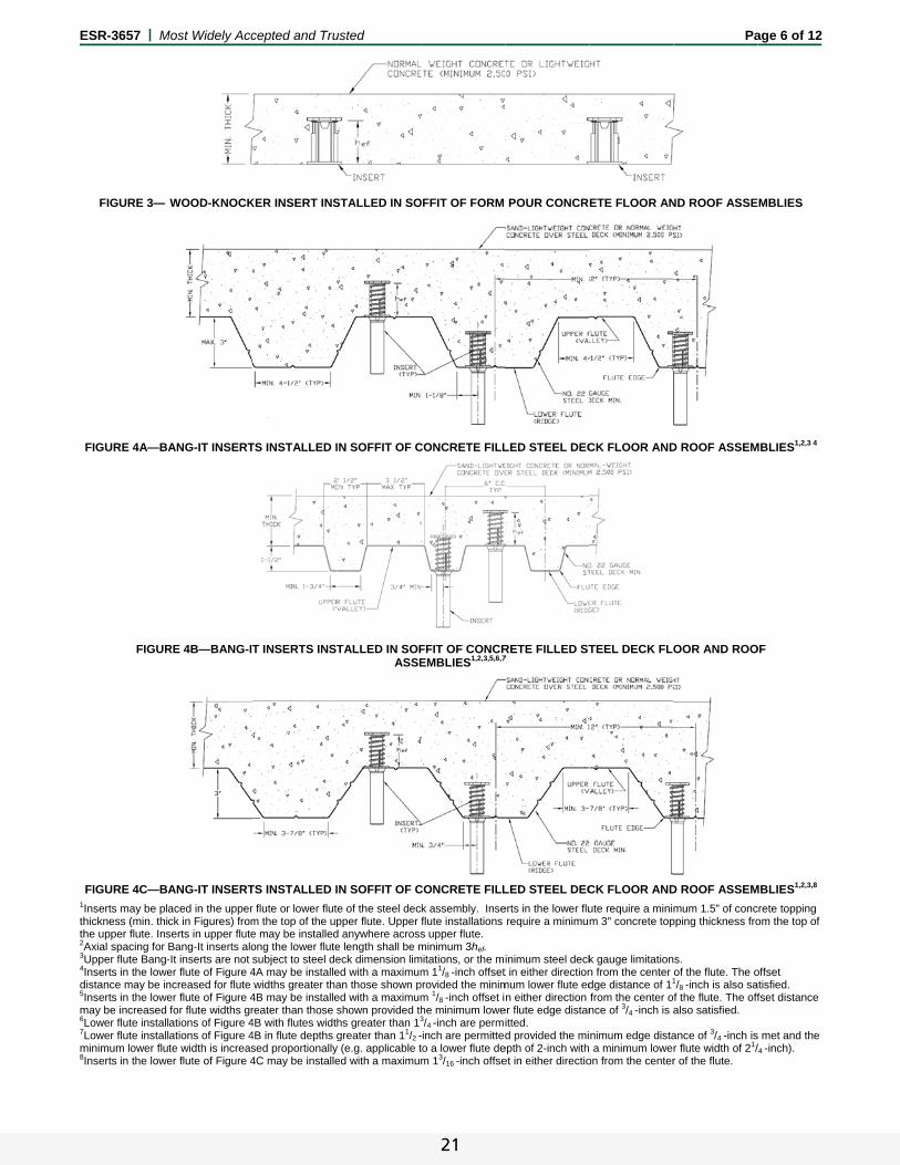
E
1
thth2A3
4
d5
m6
7
m8
ESR-3657 | M
FIGURE 3—
FIGURE 4A—BA
FIGUR
FIGURE 4C—BA
Inserts may be plahickness (min. thihe upper flute. InsAxial spacing for Upper flute Bang-Inserts in the lowe
distance may be inInserts in the lowe
may be increased Lower flute installLower flute install
minimum lower fluInserts in the lowe
Most Widely Acc
WOOD-KNOCK
ANG-IT INSERT
RE 4B—BANG-IT
ANG-IT INSERT
aced in the upperck in Figures) fromserts in upper fluteBang-It inserts alo-It inserts are not er flute of Figure 4ncreased for flute er flute of Figure 4for flute widths grations of Figure 4ations of Figure 4te width is increaser flute of Figure 4
cepted and Tru
KER INSERT INS
TS INSTALLED I
T INSERTS INS
TS INSTALLED I
r flute or lower flutm the top of the upe may be installedong the lower flutesubject to steel de4A may be installewidths greater tha
4B may be installereater than those 4B with flutes widt4B in flute depths sed proportionally4C may be installe
usted
STALLED IN SO
IN SOFFIT OF C
TALLED IN SOFASSE
IN SOFFIT OF C
te of the steel decpper flute. Upper d anywhere acrosse length shall be meck dimension limed with a maximuman those shown ped with a maximumshown provided thhs greater than 13
greater than 11/2 -y (e.g. applicable ted with a maximu
OFFIT OF FORM
CONCRETE FILL
FFIT OF CONCREMBLIES1,2,3,5,6,7
CONCRETE FILL
k assembly. Inseflute installations s upper flute. minimum 3hef.
mitations, or the mim 11/8 -inch offset
provided the minimm 1/8 -inch offset ihe minimum lowe3/4 -inch are permi-inch are permittedto a lower flute dem 13/16 -inch offse
POUR CONCR
LED STEEL DEC
RETE FILLED ST7
LED STEEL DEC
erts in the lower flurequire a minimu
inimum steel deckt in either directionmum lower flute edn either direction
er flute edge distanitted. d provided the mi
epth of 2-inch withet in either directio
ETE FLOOR AN
CK FLOOR AND
TEEL DECK FLO
CK FLOOR AND
ute require a minim 3" concrete top
k gauge limitationn from the center dge distance of 11
from the center once of 3/4 -inch is a
nimum edge dista a minimum lowe
on from the center
Pa
ND ROOF ASSE
D ROOF ASSEM
OOR AND ROO
D ROOF ASSEM
mum 1.5” of concpping thickness fro
s. of the flute. The o1/8 -inch is also saf the flute. The offalso satisfied.
ance of 3/4 -inch isr flute width of 21/r of the flute.
age 6 of 12
MBLIES
MBLIES1,2,3 4
OF
MBLIES1,2,3,8
crete topping om the top of
offset atisfied. fset distance
s met and the /4 -inch).
21
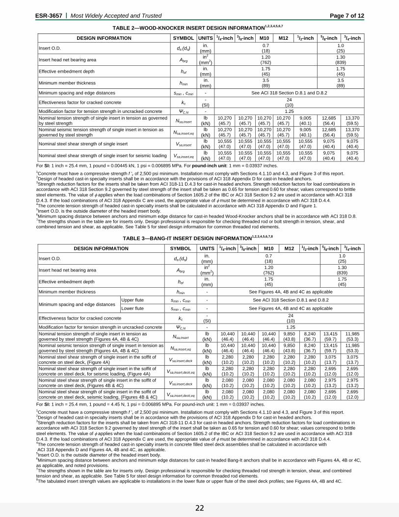
ESR-3657 | Most Widely Accepted and Trusted Page 7 of 12
TABLE 2—WOOD-KNOCKER INSERT DESIGN INFORMATION1,2,3,4,5,6,7
DESIGN INFORMATION SYMBOL UNITS 1/4-inch 3/8-inch M10 M12 1/2-inch 5/8-inch 3/4-inch
Insert O.D. da (do) in.
(mm) 0.7 (18)
1.0 (25)
Insert head net bearing area Abrg in2
(mm2)1.20 (762)
1.30 (839)
Effective embedment depth hef in.
(mm) 1.75 (45)
1.75 (45)
Minimum member thickness hmin in.
(mm) 3.5 (89)
3.5 (89)
Minimum spacing and edge distances smin , cmin - See ACI 318 Section D.8.1 and D.8.2
Effectiveness factor for cracked concrete kc -
(SI) 24
(10) Modification factor for tension strength in uncracked concrete ΨC,N - 1.25
Nominal tension strength of single insert in tension as governed by steel strength Nsa,insert
lb (kN)
10,270 (45.7)
10,270 (45.7)
10,270(45.7)
10,270 (45.7)
9,005 (40.1)
12,685 (56.4)
13,370 (59.5)
Nominal seismic tension strength of single insert in tension as governed by steel strength Nsa,insert,eq
lb (kN)
10,270 (45.7)
10,270 (45.7)
10,270(45.7)
10,270 (45.7)
9,005 (40.1)
12,685 (56.4)
13,370 (59.5)
Nominal steel shear strength of single insert Vsa,insert lb
(kN) 10,555 (47.0)
10,555 (47.0)
10,555(47.0)
10,555 (47.0)
10,555 (47.0)
9,075 (40.4)
9,075 (40.4)
Nominal steel shear strength of single insert for seismic loading Vsa,insert,eq lb
(kN) 10,555 (47.0)
10,555 (47.0)
10,555(47.0)
10,555 (47.0)
10,555 (47.0)
9,075 (40.4)
9,075 (40.4)
For SI: 1 inch = 25.4 mm, 1 pound = 0.00445 kN, 1 psi = 0.006895 MPa. For pound-inch unit: 1 mm = 0.03937 inches. 1Concrete must have a compressive strength f 'c of 2,500 psi minimum. Installation must comply with Sections 4.1.10 and 4.3, and Figure 3 of this report. 2Design of headed cast-in specialty inserts shall be in accordance with the provisions of ACI 318 Appendix D for cast-in headed anchors. 3Strength reduction factors for the inserts shall be taken from ACI 318-11 D.4.3 for cast-in headed anchors. Strength reduction factors for load combinations in accordance with ACI 318 Section 9.2 governed by steel strength of the insert shall be taken as 0.65 for tension and 0.60 for shear; values correspond to brittle steel elements. The value of applies when the load combinations of Section 1605.2 of the IBC or ACI 318 Section 9.2 are used in accordance with ACI 318 D.4.3. If the load combinations of ACI 318 Appendix C are used, the appropriate value of must be determined in accordance with ACI 318 D.4.4. 4The concrete tension strength of headed cast-in specialty inserts shall be calculated in accordance with ACI 318 Appendix D and Figure 1. 5Insert O.D. is the outside diameter of the headed insert body. 6Minimum spacing distance between anchors and minimum edge distance for cast-in headed Wood-Knocker anchors shall be in accordance with ACI 318 D.8. 7The strengths shown in the table are for inserts only. Design professional is responsible for checking threaded rod or bolt strength in tension, shear, and combined tension and shear, as applicable. See Table 5 for steel design information for common threaded rod elements.
TABLE 3—BANG-IT INSERT DESIGN INFORMATION1,2,3,4,5,6,7,8
DESIGN INFORMATION SYMBOL UNITS 1/4-inch 3/8-inch M10 M12 1/2-inch 5/8-inch 3/4-inch
Insert O.D. da (do) in.
(mm) 0.7 (18)
1.0 (25)
Insert head net bearing area Abrg in2
(mm2) 1.20 (762)
1.30 (839)
Effective embedment depth hef in.
(mm) 1.75 (45)
1.75 (45)
Minimum member thickness hmin - See Figures 4A, 4B and 4C as applicable
Minimum spacing and edge distances Upper flute smin , cmin - See ACI 318 Section D.8.1 and D.8.2
Lower flute smin , cmin - See Figures 4A, 4B and 4C as applicable
Effectiveness factor for cracked concrete kc -
(SI) 24
(10) Modification factor for tension strength in uncracked concrete ΨC,N - 1.25
Nominal tension strength of single insert in tension as governed by steel strength (Figures 4A, 4B & 4C) Nsa,insert
lb (kN)
10,440 (46.4)
10,440 (46.4)
10,440 (46.4)
9,850 (43.8)
8,240 (36.7)
13,415 (59.7)
11,985 (53.3)
Nominal seismic tension strength of single insert in tension as governed by steel strength (Figures 4A, 4B & 4C) Nsa,insert,eq
lb (kN)
10,440 (46.4)
10,440 (46.4)
10,440 (46.4)
9,850 (43.8)
8,240 (36.7)
13,415 (59.7)
11,985 (53.3)
Nominal steel shear strength of single insert in the soffit of concrete on steel deck, (Figure 4A) Vsa,insert,deck
lb (kN)
2,280 (10.2)
2,280 (10.2)
2,280 (10.2)
2,280 (10.2)
2,280 (10.2)
3,075 (13.7)
3,075 (13.7)
Nominal steel shear strength of single insert in the soffit of concrete on steel deck, for seismic loading, (Figure 4A) Vsa,insert,deck,eq
lb (kN)
2,280 (10.2)
2,280 (10.2)
2,280 (10.2)
2,280 (10.2)
2,280 (10.2)
2,695 (12.0)
2,695 (12.0)
Nominal steel shear strength of single insert in the soffit of concrete on steel deck, (Figures 4B & 4C) Vsa,insert,deck
lb (kN)
2,080 (10.2)
2,080 (10.2)
2,080 (10.2)
2,080 (10.2)
2,080 (10.2)
2,975 (13.2)
2,975 (13.2)
Nominal steel shear strength of single insert in the soffit of concrete on steel deck, seismic loading, (Figures 4B & 4C) Vsa,insert,deck,eq
lb (kN)
2,080 (10.2)
2,080 (10.2)
2,080 (10.2)
2,080 (10.2)
2,080 (10.2)
2,695 (12.0)
2,695 (12.0)
For SI: 1 inch = 25.4 mm, 1 pound = 4.45 N, 1 psi = 0.006895 MPa. For pound-inch unit: 1 mm = 0.03937 inches. 1Concrete must have a compressive strength f 'c of 2,500 psi minimum. Installation must comply with Sections 4.1.10 and 4.3, and Figure 3 of this report. 2Design of headed cast-in specialty inserts shall be in accordance with the provisions of ACI 318 Appendix D for cast-in headed anchors. 3Strength reduction factors for the inserts shall be taken from ACI 318-11 D.4.3 for cast-in headed anchors. Strength reduction factors for load combinations in accordance with ACI 318 Section 9.2 governed by steel strength of the insert shall be taken as 0.65 for tension and 0.60 for shear; values correspond to brittle steel elements. The value of applies when the load combinations of Section 1605.2 of the IBC or ACI 318 Section 9.2 are used in accordance with ACI 318 D.4.3. If the load combinations of ACI 318 Appendix C are used, the appropriate value of must be determined in accordance with ACI 318 D.4.4. 4The concrete tension strength of headed cast-in specialty inserts in concrete filled steel deck assemblies shall be calculated in accordance with ACI 318 Appendix D and Figures 4A, 4B and 4C, as applicable. 5Insert O.D. is the outside diameter of the headed insert body. 6Minimum spacing distance between anchors and minimum edge distances for cast-in headed Bang-It anchors shall be in accordance with Figures 4A, 4B or 4C, as applicable, and noted provisions. 7The strengths shown in the table are for inserts only. Design professional is responsible for checking threaded rod strength in tension, shear, and combined tension and shear, as applicable. See Table 5 for steel design information for common threaded rod elements. 8The tabulated insert strength values are applicable to installations in the lower flute or upper flute of the steel deck profiles; see Figures 4A, 4B and 4C.
22
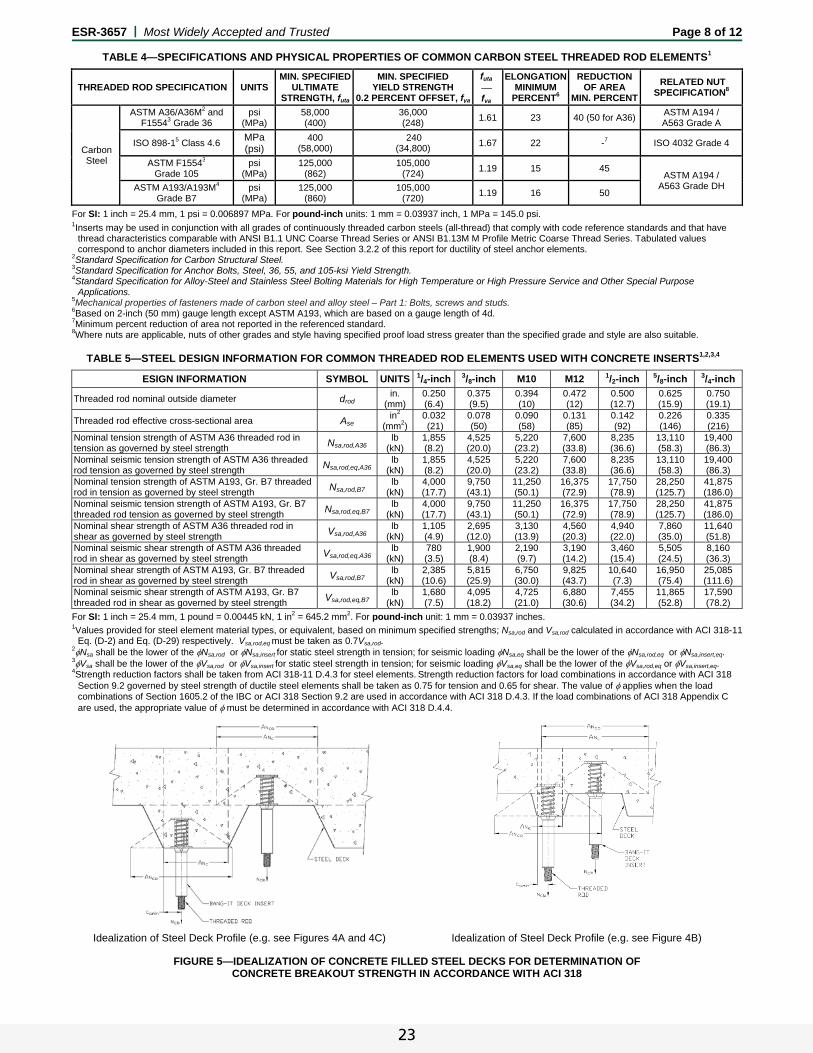
ESR-3657 | Most Widely Accepted and Trusted Page 8 of 12
TABLE 4—SPECIFICATIONS AND PHYSICAL PROPERTIES OF COMMON CARBON STEEL THREADED ROD ELEMENTS1
THREADED ROD SPECIFICATION UNITS MIN. SPECIFIED
ULTIMATE STRENGTH, futa
MIN. SPECIFIED YIELD STRENGTH
0.2 PERCENT OFFSET, fya
futa fya
ELONGATIONMINIMUM
PERCENT6
REDUCTION OF AREA
MIN. PERCENT
RELATED NUT SPECIFICATION8
Carbon Steel
ASTM A36/A36M2 and F15543 Grade 36
psi (MPa)
58,000 (400)
36,000 (248)
1.61 23 40 (50 for A36) ASTM A194 / A563 Grade A
ISO 898-15 Class 4.6 MPa (psi)
400 (58,000)
240 (34,800)
1.67 22 -7 ISO 4032 Grade 4
ASTM F15543 Grade 105
psi (MPa)
125,000 (862)
105,000 (724)
1.19 15 45 ASTM A194 /
A563 Grade DH ASTM A193/A193M4 Grade B7
psi (MPa)
125,000 (860)
105,000 (720)
1.19 16 50
For SI: 1 inch = 25.4 mm, 1 psi = 0.006897 MPa. For pound-inch units: 1 mm = 0.03937 inch, 1 MPa = 145.0 psi.
1Inserts may be used in conjunction with all grades of continuously threaded carbon steels (all-thread) that comply with code reference standards and that have thread characteristics comparable with ANSI B1.1 UNC Coarse Thread Series or ANSI B1.13M M Profile Metric Coarse Thread Series. Tabulated values correspond to anchor diameters included in this report. See Section 3.2.2 of this report for ductility of steel anchor elements.
2Standard Specification for Carbon Structural Steel. 3Standard Specification for Anchor Bolts, Steel, 36, 55, and 105-ksi Yield Strength. 4Standard Specification for Alloy-Steel and Stainless Steel Bolting Materials for High Temperature or High Pressure Service and Other Special Purpose
Applications. 5Mechanical properties of fasteners made of carbon steel and alloy steel – Part 1: Bolts, screws and studs. 6Based on 2-inch (50 mm) gauge length except ASTM A193, which are based on a gauge length of 4d. 7Minimum percent reduction of area not reported in the referenced standard. 8Where nuts are applicable, nuts of other grades and style having specified proof load stress greater than the specified grade and style are also suitable.
TABLE 5—STEEL DESIGN INFORMATION FOR COMMON THREADED ROD ELEMENTS USED WITH CONCRETE INSERTS1,2,3,4
ESIGN INFORMATION SYMBOL UNITS 1/4-inch 3/8-inch M10 M12 1/2-inch 5/8-inch 3/4-inch
Threaded rod nominal outside diameter drod in.
(mm) 0.250 (6.4)
0.375 (9.5)
0.394 (10)
0.472 (12)
0.500 (12.7)
0.625 (15.9)
0.750 (19.1)
Threaded rod effective cross-sectional area Ase in2
(mm2)0.032 (21)
0.078 (50)
0.090 (58)
0.131 (85)
0.142 (92)
0.226 (146)
0.335 (216)
Nominal tension strength of ASTM A36 threaded rod in tension as governed by steel strength Nsa,rod,A36
lb (kN)
1,855 (8.2)
4,525 (20.0)
5,220 (23.2)
7,600 (33.8)
8,235 (36.6)
13,110 (58.3)
19,400 (86.3)
Nominal seismic tension strength of ASTM A36 threaded rod tension as governed by steel strength Nsa,rod,eq,A36
lb (kN)
1,855 (8.2)
4,525 (20.0)
5,220 (23.2)
7,600 (33.8)
8,235 (36.6)
13,110 (58.3)
19,400 (86.3)
Nominal tension strength of ASTM A193, Gr. B7 threaded rod in tension as governed by steel strength Nsa,rod,B7
lb (kN)
4,000 (17.7)
9,750 (43.1)
11,250 (50.1)
16,375 (72.9)
17,750 (78.9)
28,250 (125.7)
41,875 (186.0)
Nominal seismic tension strength of ASTM A193, Gr. B7 threaded rod tension as governed by steel strength Nsa,rod,eq,B7
lb (kN)
4,000 (17.7)
9,750 (43.1)
11,250 (50.1)
16,375 (72.9)
17,750 (78.9)
28,250 (125.7)
41,875 (186.0)
Nominal shear strength of ASTM A36 threaded rod in shear as governed by steel strength Vsa,rod,A36
lb (kN)
1,105 (4.9)
2,695 (12.0)
3,130 (13.9)
4,560 (20.3)
4,940 (22.0)
7,860 (35.0)
11,640 (51.8)
Nominal seismic shear strength of ASTM A36 threaded rod in shear as governed by steel strength Vsa,rod,eq,A36
lb (kN)
780 (3.5)
1,900 (8.4)
2,190 (9.7)
3,190 (14.2)
3,460 (15.4)
5,505 (24.5)
8,160 (36.3)
Nominal shear strength of ASTM A193, Gr. B7 threaded rod in shear as governed by steel strength Vsa,rod,B7
lb (kN)
2,385 (10.6)
5,815 (25.9)
6,750 (30.0)
9,825 (43.7)
10,640 (7.3)
16,950 (75.4)
25,085 (111.6)
Nominal seismic shear strength of ASTM A193, Gr. B7 threaded rod in shear as governed by steel strength Vsa,rod,eq,B7
lb (kN)
1,680 (7.5)
4,095 (18.2)
4,725 (21.0)
6,880 (30.6)
7,455 (34.2)
11,865 (52.8)
17,590 (78.2)
For SI: 1 inch = 25.4 mm, 1 pound = 0.00445 kN, 1 in2 = 645.2 mm2. For pound-inch unit: 1 mm = 0.03937 inches. 1Values provided for steel element material types, or equivalent, based on minimum specified strengths; Nsa,rod and Vsa,rod calculated in accordance with ACI 318-11
Eq. (D-2) and Eq. (D-29) respectively. Vsa,rod,eq must be taken as 0.7Vsa,rod. 2Nsa shall be the lower of the Nsa,rod or Nsa,insert for static steel strength in tension; for seismic loading Nsa,eq shall be the lower of the Nsa,rod,eq or Nsa,insert,eq. 3Vsa shall be the lower of the Vsa,rod or Vsa,insert for static steel strength in tension; for seismic loading Vsa,eq shall be the lower of the Vsa,rod,eq or Vsa,insert,eq. 4Strength reduction factors shall be taken from ACI 318-11 D.4.3 for steel elements. Strength reduction factors for load combinations in accordance with ACI 318
Section 9.2 governed by steel strength of ductile steel elements shall be taken as 0.75 for tension and 0.65 for shear. The value of applies when the load combinations of Section 1605.2 of the IBC or ACI 318 Section 9.2 are used in accordance with ACI 318 D.4.3. If the load combinations of ACI 318 Appendix C are used, the appropriate value of must be determined in accordance with ACI 318 D.4.4.
Idealization of Steel Deck Profile (e.g. see Figures 4A and 4C) Idealization of Steel Deck Profile (e.g. see Figure 4B)
FIGURE 5—IDEALIZATION OF CONCRETE FILLED STEEL DECKS FOR DETERMINATION OF CONCRETE BREAKOUT STRENGTH IN ACCORDANCE WITH ACI 318
23

ESR-3657 | Most Widely Accepted and Trusted Page 9 of 12
TABLE 6—EXAMPLE ASD ALLOWABLE TENSION DESIGN VALUES FOR ILLUSTRATIVE PURPOSES1,2,3,4,5,6,7,8,9,10
CONCRETE STRENGTH
(f’c)
THREADED ROD
SPECIFICATION
WOOD-KNOCKER IN CONCRETE
1/4-INCH (lbs)
3/8-INCH (lbs)
M10 (lbs)
M12 (lbs)
1/2-INCH (lbs)
5/8-INCH (lbs)
3/4-INCH (lbs)
2,500 A36 940 1,640 1,640 1,640 1,640 1,640 1,640
A193, Gr. B7 1,640 1,640 1,640 1,640 1,640 1,640 1,640
3,000 A36 940 1,800 1,800 1,800 1,800 1,800 1,800
A193, Gr. B7 1,800 1,800 1,800 1,800 1,800 1,800 1,800
4,000 A36 940 2,080 2,080 2,080 2,080 2,080 2,080
A193, Gr. B7 2,025 2,080 2,080 2,080 2,080 2,080 2,080
6,000 A36 940 2,295 2,545 2,545 2,545 2,545 2,545
A193, Gr. B7 2,025 2,545 2,545 2,545 2,545 2,545 2,545
8,000 A36 940 2,295 2,645 2,940 2,940 2,940 2,940
A193, Gr. B7 2,025 2,940 2,940 2,940 2,940 2,940 2,940
10,000 A36 940 2,295 2,645 3,285 3,285 3,285 3,285
A193, Gr. B7 2,025 3,285 3,285 3,285 3,285 3,285 3,285
For SI: 1 pound = 4.45 N. For pound-inch unit: 1 inch = 25.4 mm.
Illustrative Allowable Stress Design Values in Table 6 are applicable only when all of the following design assumptions are followed: 1Concrete compressive strength, f'c, given for normal weight concrete. 2Single anchors with static tension load with installation in accordance to Figure 3 for Wood-Knocker. 3Concrete determined to remain uncracked for the life of the anchorage. 4Load combinations from ACI 318 Section 9.2 (no seismic loading). 530% dead load and 70% live load, controlling load combination 1.2D + 1.6 L. 6Calculation of the weighted average for α = 1.2*0.3 + 1.6*0.7 = 1.48. 7Assuming no edge distance influence (ca1 ≥ 1.5hef) and no side-face blowout in tension for Wood-Knocker. 9h ≥ hmin according to ACI 318 Section D.8. 10Values are for Condition B where supplementary reinforcement in accordance with ACI 318-11 D.4.3 is not provided.
TABLE 7—EXAMPLE ASD ALLOWABLE SHEAR DESIGN VALUE FOR ILLUSTRATIVE PURPOSES1,2,3,4,5,6,7,8,9,10
CONCRETE STRENGTH
(f’c)
THREADED ROD
SPECIFICATION
WOOD-KNOCKER IN CONCRETE 1/4-INCH
(lbs)
3/8-INCH (lbs)
M10 (lbs)
M12 (lbs)
1/2-INCH (lbs)
5/8-INCH (lbs)
3/4-INCH (lbs)
2,500 A36 490 1,195 1,375 1,640 1,640 1,640 1,640
A193, Gr. B7 1,055 1,640 1,640 1,640 1,640 1,640 1,640
3,000 A36 490 1,195 1,375 1,800 1,800 1,800 1,800
A193, Gr. B7 1,055 1,800 1,800 1,800 1,800 1,800 1,800
4,000 A36 490 1,195 1,375 2,005 2,080 2,080 2,080
A193, Gr. B7 1,055 2,080 2,080 2,080 2,080 2,080 2,080
6,000 A36 490 1,195 1,375 2,005 2,170 2,545 2,545
A193, Gr. B7 1,055 2,545 2,545 2,545 2,545 2,545 2,545
8,000 A36 490 1,195 1,375 2,005 2,170 2,940 2,940
A193, Gr. B7 1,055 2,570 2,940 2,940 2,940 2,940 2,940
10,000 A36 490 1,195 1,375 2,005 2,170 3,285 3,285
A193, Gr. B7 1,055 2,570 2,965 3,285 3,285 3,285 3,285
For SI: 1 pound = 4.45 N. For pound-inch unit: 1 inch = 25.4 mm.
Illustrative Allowable Stress Design Values in Table 7 are applicable only when all of the following design assumptions are followed: 1Concrete compressive strength, f'c, given for normal weight concrete. 2Single anchors with static shear load with installation in accordance with Figure 3 for Wood-Knocker. 3Concrete determined to remain uncracked for the life of the anchorage. 4Load combinations from ACI 318 Section 9.2 (no seismic loading). 530% dead load and 70% live load, controlling load combination 1.2D + 1.6 L. 6Calculation of the weighted average for α = 1.2*0.3 + 1.6*0.7 = 1.48. 7Assuming no edge distance (ca1 ≥ 1.5hef) or corner distance influence (ca2 ≥ 1.5ca1) for Wood-Knocker anchors. 8Shear loads may be applied in any direction. 9h ≥ hmin according to ACI 318 Section D.8. 10Values are for Condition B where supplementary reinforcement in accordance with ACI 318-11 D.4.3 is not provided.
WOOD-KNOCKER BANG-IT
1/4-INCH 3/8-INCH M10 M12 1/2-INCH 5/8-INCH 3/4-INCH 1/4-INCH 3/8-INCH M10 M12 1/2-INCH 5/8-INCH 3/4-INCH
Brown Green Green Yellow Yellow Red Purple Brown Green Green Yellow Yellow Red Purple
FIGURE 6—WOOD-KNOCKER CONCRETE INSERTS AND BANG-IT INSERTS FOR CONCRETE-FILLED STEEL DECKS
24

ESR-3657 | Most Widely Accepted and Trusted Page 10 of 12
TABLE 8—EXAMPLE ASD ALLOWABLE TENSION DESIGN VALUES FOR ILLUSTRATIVE PURPOSES1,2,3,4,5,6,7,8,9
CONCRETE STRENGTH
(f’c)
THREADED ROD
SPECIFICATION
BANG-IT IN CONCRETE-FILLED STEEL DECK (FIGURE 4A)10 1/4-INCH
(lbs)
3/8-INCH(lbs)
M10(lbs)
M12(lbs)
1/2-INCH(lbs)
5/8-INCH (lbs)
3/4-INCH(lbs)
Upper Lower Upper Lower Upper Lower Upper Lower Upper Lower Upper Lower Upper Lower
2,500 A36 940 830 1,395 830 1,395 830 1,395 830 1,395 830 1,395 830 1,395 830
A193, Gr. B7 1,395 830 1,395 830 1,395 830 1,395 830 1,395 830 1,395 830 1,395 830
3,000 A36 940 905 1,530 905 1,530 905 1,530 905 1,530 905 1,530 905 1,530 905
A193, Gr. B7 1,530 905 1,530 905 1,530 905 1,530 905 1,530 905 1,530 905 1,530 905
4,000 A36 940 940 1,765 1,045 1,765 1,045 1,765 1,045 1,765 1,045 1,765 1,045 1,765 1,045
A193, Gr. B7 1,765 1,045 1,765 1,045 1,765 1,045 1,765 1,045 1,765 1,045 1,765 1,045 1,765 1,045
6,000 A36 940 940 2,160 1,280 2,160 1,280 2,160 1,280 2,160 1,280 2,160 1,280 2,160 1,280
A193, Gr. B7 2,025 1,280 2,160 1,280 2,160 1,280 2,160 1,280 2,160 1,280 2,160 1,280 2,160 1,280
8,000 A36 940 940 2,295 1,475 2,495 1,475 2,495 1,475 2,495 1,475 2,495 1,475 2,495 1,475
A193, Gr. B7 2,025 1,475 2,495 1,475 2,495 1,475 2,495 1,475 2,495 1,475 2,495 1,475 2,495 1,475
10,000 A36 940 940 2,295 1,650 2,645 1,650 2,790 1,650 2,790 1,650 2,790 1,650 2,790 1,650
A193, Gr. B7 2,025 1,650 2,790 1,650 2,790 1,650 2,790 1,650 2,790 1,650 2,790 1,650 2,790 1,650
CONCRETE STRENGTH
(f’c)
THREADED ROD
SPECIFICATION
BANG-IT IN CONCRETE-FILLED STEEL DECK (FIGURE 4B)11 1/4-INCH
(lbs)
3/8-INCH(lbs)
M10(lbs)
M12(lbs)
1/2-INCH(lbs)
5/8-INCH (lbs)
3/4-INCH(lbs)
Upper Lower Upper Lower Upper Lower Upper Lower Upper Lower Upper Lower Upper Lower
2,500 A36 940 365 1,395 365 1,395 365 1,395 365 1,395 365 1,395 365 1,395 365
A193, Gr. B7 1,395 365 1,395 365 1,395 365 1,395 365 1,395 365 1,395 365 1,395 365
3,000 A36 940 400 1,530 400 1,530 400 1,530 400 1,530 400 1,530 400 1,530 400
A193, Gr. B7 1,530 400 1,530 400 1,530 400 1,530 400 1,530 400 1,530 400 1,530 400
4,000 A36 940 465 1,765 465 1,765 465 1,765 465 1,765 465 1,765 465 1,765 465
A193, Gr. B7 1,765 465 1,765 465 1,765 465 1,765 465 1,765 465 1,765 465 1,765 465
6,000 A36 940 570 2,160 570 2,160 570 2,160 570 2,160 570 2,160 570 2,160 570
A193, Gr. B7 2,025 570 2,160 570 2,160 570 2,160 570 2,160 570 2,160 570 2,160 570
8,000 A36 940 655 2,295 655 2,495 655 2,495 655 2,495 655 2,495 655 2,495 655
A193, Gr. B7 2,025 655 2,495 655 2,495 655 2,495 655 2,495 655 2,495 655 2,495 655
10,000 A36 940 730 2,295 730 2,645 730 2,790 730 2,790 730 2,790 730 2,790 730
A193, Gr. B7 2,025 730 2,790 730 2,790 730 2,790 730 2,790 730 2,790 730 2,790 730
CONCRETE STRENGTH
(f’c)
THREADED ROD
SPECIFICATION
BANG-IT IN CONCRETE-FILLED STEEL DECK (FIGURE 4C)12 1/4-INCH
(lbs)
3/8-INCH(lbs)
M10(lbs)
M12(lbs)
1/2-INCH(lbs)
5/8-INCH (lbs)
3/4-INCH(lbs)
Upper Lower Upper Lower Upper Lower Upper Lower Upper Lower Upper Lower Upper Lower
2,500 A36 940 705 1,395 705 1,395 705 1,395 705 1,395 705 1,395 705 1,395 705
A193, Gr. B7 1,395 705 1,395 705 1,395 705 1,395 705 1,395 705 1,395 705 1,395 705
3,000 A36 940 775 1,530 775 1,530 775 1,530 775 1,530 775 1,530 775 1,530 775
A193, Gr. B7 1,530 775 1,530 775 1,530 775 1,530 775 1,530 775 1,530 775 1,530 775
4,000 A36 940 890 1,765 890 1,765 890 1,765 890 1,765 890 1,765 890 1,765 890
A193, Gr. B7 1,765 890 1,765 890 1,765 890 1,765 890 1,765 890 1,765 890 1,765 890
6,000 A36 940 940 2,160 1,090 2,160 1,090 2,160 1,090 2,160 1,090 2,160 1,090 2,160 1,090
A193, Gr. B7 2,025 1,090 2,160 1,090 2,160 1,090 2,160 1,090 2,160 1,090 2,160 1,090 2,160 1,090
8,000 A36 940 940 2,295 1,260 2,495 1,260 2,495 1,260 2,495 1,260 2,495 1,260 2,495 1,260
A193, Gr. B7 2,025 1,260 2,495 1,260 2,495 1,260 2,495 1,260 2,495 1,260 2,495 1,260 2,495 1,260
10,000 A36 940 940 2,295 1,410 2,645 1,410 2,790 1,410 2,790 1,410 2,790 1,410 2,790 1,410
A193, Gr. B7 2,025 1,410 2,790 1,410 2,790 1,410 2,790 1,410 2,790 1,410 2,790 1,410 2,790 1,410
For SI: 1 pound = 4.45 N. For pound-inch unit: 1 inch = 25.4 mm.
Illustrative Allowable Stress Design Values in Table 8 are applicable only when all of the following design assumptions are followed: 1Concrete compressive strength, f'c, given for sand-light weight concrete for Bang-It anchors. 2Single anchors; static tension load with installation in upper and lower flute locations in concrete-filled steel deck in accordance with Figures 4A, 4B or 4C, as applicable, and noted provisions. 3Concrete determined to remain uncracked for the life of the anchorage. 4Load combinations from ACI 318 Section 9.2 (no seismic loading). 530% dead load and 70% live load, controlling load combination 1.2D + 1.6 L. 6Calculation of the weighted average for α = 1.2*0.3 + 1.6*0.7 = 1.48. 7h ≥ hmin according to ACI 318 Section D.8. 8Values are for Condition B where supplementary reinforcement in accordance with ACI 318-11 D.4.3 is not provided. 9Assuming no edge distance influence with Ψed,N = 1.0 and no side-face blowout in tension for upper flute Bang-It anchors. 10For lower flute Bang-It anchors, the near edge distance, ca,min, is 1.125-inch (see Figure 4A). 11For lower flute Bang-It anchors, the near edge distance, ca,min, is 0.75-inch (see Figure 4B). 12For lower flute Bang-It anchors, the near edge distance, ca,min, is 0.75-inch (see Figure 4C).
25

ESR-3657 | Most Widely Accepted and Trusted Page 11 of 12
TABLE 9—EXAMPLE ASD ALLOWABLE SHEAR DESIGN VALUE FOR ILLUSTRATIVE PURPOSES1,2,3,4,5,6,7,8,9,10
CONCRETE STRENGTH
(f’c)
THREADED ROD
SPECIFICATION
BANG-IT IN CONCRETE-FILLED STEEL DECK (FIGURE 4A) 1/4-INCH
(lbs)
3/8-INCH(lbs)
M10(lbs)
M12(lbs)
1/2-INCH(lbs)
5/8-INCH (lbs)
3/4-INCH(lbs)
Upper Lower Upper Lower Upper Lower Upper Lower Upper Lower Upper Lower Upper Lower
2,500 to 10,000
A36 490 490 925 925 925 925 925 925 925 925 1,245 1,245 1,245 1,245A193, Gr. B7 925 925 925 925 925 925 925 925 925 925 1,245 1,245 1,245 1,245
CONCRETE STRENGTH
(f’c)
THREADED ROD
SPECIFICATION
BANG-IT IN CONCRETE-FILLED STEEL DECK (FIGURE 4B) 1/4-INCH
(lbs)
3/8-INCH(lbs)
M10(lbs)
M12(lbs)
1/2-INCH(lbs)
5/8-INCH (lbs)
3/4-INCH(lbs)
Upper Lower Upper Lower Upper Lower Upper Lower Upper Lower Upper Lower Upper Lower
2,500 to 10,000
A36 490 490 845 845 845 845 845 845 845 845 1,205 1,205 1,205 1,205A193, Gr. B7 845 845 845 845 845 845 845 845 845 845 1,205 1,205 1,205 1,205
CONCRETE STRENGTH
(f’c)
THREADED ROD
SPECIFICATION
BANG-IT IN CONCRETE-FILLED STEEL DECK (FIGURE 4C) 1/4-INCH
(lbs)
3/8-INCH(lbs)
M10(lbs)
M12(lbs)
1/2-INCH(lbs)
5/8-INCH (lbs)
3/4-INCH(lbs)
Upper Lower Upper Lower Upper Lower Upper Lower Upper Lower Upper Lower Upper Lower
2,500 to 10,000
A36 490 490 845 845 845 845 845 845 845 845 1,205 1,205 1,205 1,205A193, Gr. B7 845 845 845 845 845 845 845 845 845 845 1,205 1,205 1,205 1,205
For SI: 1 pound = 4.45 N. For pound-inch unit: 1 inch = 25.4 mm.
Illustrative Allowable Stress Design Values in Table 9 are applicable only when all of the following design assumptions are followed: 1Concrete compressive strength, f'c, given for sand-light weight for Bang-It anchors. 2Single anchors; static shear load with installation in upper and lower flute locations in concrete-filled steel deck in accordance with Figures 4A, 4B or 4C, as applicable, and noted provisions. 3Concrete determined to remain uncracked for the life of the anchorage. 4Load combinations from ACI 318 Section 9.2 (no seismic loading). 530% dead load and 70% live load, controlling load combination 1.2D + 1.6 L. 6Calculation of the weighted average for α = 1.2*0.3 + 1.6*0.7 = 1.48. 7Assuming no edge distance (ca1 ≥ 1.5hef) or corner distance influence (ca2 ≥ 1.5ca1) upper flute Bang-It anchors. 8Shear loads may be applied in any direction. 9h ≥ hmin according to ACI 318 Section D.8. 10Values are for Condition B where supplementary reinforcement in accordance with ACI 318-11 D.4.3 is not provided.
WO
OD
-KN
OC
KE
R
1.) Position insert on formwork nails down.
2.) Drive insert down until flush with the form.
3.) After formwork removal, remove nails as necessary (e.g. flush mounted fixtures).
4.) After concrete has reached design strength, install threaded steel element (rod/bolt) into the insert or attach fixture as applicable (e.g. seismic brace).
POSITION DRIVE PREPARE ATTACH
BA
NG
-IT
1.) Cut (e.g. drill/punch) a hole in the steel deck to the hole size required by the insert.
2.) Place the plastic sleeve of the insert through hole in steel deck.
3.) Step on or impact the insert head to engage. Optionally, base plate of insert can also be screwed to steel deck.
4.) After concrete has reached design strength, install threaded steel element (rod/bolt) into the insert. Trim away plastic sleeve for shear load applications and attach fixture as applicable (e.g. seismic brace).
CREATE HOLE POSITION PREPARE ATTACH
FIGURE 7— WOOD-KNOCKER AND BANG-IT CONCRETE INSERTS
MANUFACTUER PUBLISHED INSTALLATION INSTRUCTIONS (MPII)
26
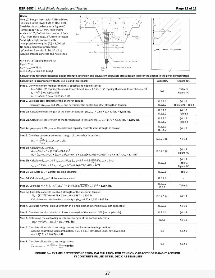
E
ESR-3657 | M
Given: One
3/8” Bang‐It in
installed in the loSteel deck in acco of this report (3
7/
Anchor is 13/16” of
(3/4” from close e
Sand‐lightweight c compressive streNo supplemental (Condition B per Assume cracked c
ha = 5 in. (2” topphef = 1.75 in. ca1 = ca,min = 0.75 inca2 ≥ 1.5hef (∴take
Calculate the fact
Calculation in acc
Step 1. Verify minha = 5.0 sa = N/Aca1 = 0.7
Step 2. Calculate s
Calculate
Step 2a. Calculate
Step 2b. Calculate
Step 2c. Nsa,rod,A36
Step 3. Calculate c
Step 3a. CalculateANco = 9hAnc = (ca1
Step 3b. Calculate
ca,min = 0
Step 3c. Calculate
Step 3d. Calculate
Step 3f. Calculate
Step 3g. Calculate Ncb = (1
Calculat
Step 4. Calculate n
Step 5. Calculate n
Step 6. Determine
Nn= m
Step 7. Calculate aAssume α = 1.2(0
Step 8. Calculate a
FIG
Most Widely Acc
nsert with ASTM Aower flute of steelrdance with Figur/8” min. flute widtffset from center oedge, 3
1/8 from far
concrete with ength: (f’c) = 3,000reinforcement: ACI 318‐11 D.4.3 concrete and no se
ing thickness)
n. en as 1.5hef)
tored resistance d
ordance with ACI
nimum member thin. (2” topping thi
A (not applicable) 5 in. ≥ ca,min = 0.75
steel strength of t
Nsa,insert and Nsa
e steel strength of
e steel strength of
6 < Nsa,insert ∴ thr
concrete breakout
, ,
e ANco and ANc hef
2 = 9 • (1.75)
2 =
1 + (1.5hef)) • (ca2 +
e ψed,N = 1.0 if ca,min
.75 in. < 1.5hef ∴ ψ
e ψc,N = 1.0 (for cra
e ψcp,N = 1.0 (for ca
Nb = ′
e concrete breakou7.7/27.6) • 0.79 •
e concrete breako
nominal pullout st
nominal side‐face
e the controlling re
in| , | = N
allowable stress dcontrolling load c0.3) + 1.6(0.7) = 1.
allowable stress d
, .
URE 8— EXAMP
cepted and Tru
A36 rod deck e 4C th) of flute r edge)
0 psi
c) eismic
esign strength in t
318‐11 and this r
ickness, spacing ackness, lower flut
in. ∴ OK
he anchor in tensi
a,rod and determine
the insert in tensi
the threaded rod
eaded rod capacit
t strength of the a
,
27.6 in.2
+ 1.5hef) = (0.75 + 2
n ≥ 1.5hef ; ψed,N = 0
ψed,N = 0.7 + 0.3•(0
cked concrete)
ast‐in anchors)
. = 24 0.85 √
ut strength of the 1.0 • 1.0 • 2,587
out capacity = Ncb
trength of a single
blowout strength
esistance strength
Ncb = 917 lbs.
esign conversion fombination: 1.2D .48
esign value:
= 620 lbs.
PLE STRENGTH IN CO
usted
tension and equiv
eport:
nd edge distance:e) ≥ hmin = 4.5 in. (
on:
e the controlling st
on: Nsa,insert = 0.6
in tension: Nsa,rod
ty controls steel st
nchor in tension:
2.625)•((2.625 + 2
0.7 0.3 ,
. if ca
0.75/2.625) = 0.79
√3,000 • 1.75 . =
anchor in tension= 1,310 lbs.
b = 0.70 • 1,310 = 9
anchor in tension
of the anchor: N/
h of the anchor in t
factor for loading + 1.6L ; 30% Dead
H DESIGN CALCONCRETE-FILLE
valent allowable s
1.5” topping thick
teel strength in ten
5 • 10,440 lbs. = 6
d,A36 = 0.75 • 4,525
trength in tension
.625)) = 17.7 in.2 ∴
a,min < 1.5hef
2,587 lbs.
:
917 lbs.
n: N/A (not applica
/A (not applicable)
tension:
condition: d Load, 70% Live Lo
CULATION FORED STEEL DEC
stress design load
kness, lower flute)
nsion
6,785 lbs.
5 lbs. = 3,395 lbs.
∴ANc = 17.7 in.2
able)
)
oad
R TENSION CAPCK ASSEMBLIES
for the anchor in
Cod
∴ OK D
D.5D.5
D.5D.5
D.5D.5
D.5D.5
D.5.
D.5.
D.5
D.5
D.5
D.5D
D.5.
D.5
D.5
D
9
9
PACITY OF BANS
Pag
the given configu
de Ref. Rep
D.8 TaFig
5.1.1 5.1.2
§Table 3
5.1.1 5.1.2
§ T
5.1.1 5.1.2
§ T
5.1.1 5.1.2
§
2.1 (b) §
2.1 (b) §
Fig
5.2.5 §TaFig
5.2.6 Ta
5.2.7
5.2.2 D.3.6
Ta
2.1 (a) §
5.3.1 §
5.4.1 §
D.4.1 §
9.2 §
9.2 §
NG-IT ANCHOR
ge 12 of 12
uration.
port Ref.
able 3 gure 4C
§4.1.2 and Table 5
§4.1.2able 3
§4.1.2able 3
§4.1.2
§4.1.3
§4.1.3 gure 4C
§4.1.3able 3 gure 4C
able 3
‐
able 3
§4.1.3
§4.1.1
§4.1.4
§4.1.1
§4.2.1
§4.2.1
27