production and applications of formaldehyde-free phenolic
TRANSCRIPT
Western University Western University
Scholarship@Western Scholarship@Western
Electronic Thesis and Dissertation Repository
12-17-2014 12:00 AM
Production and Applications of Formaldehyde-Free Phenolic Production and Applications of Formaldehyde-Free Phenolic
Resins Using 5-Hydroxymethylfurfural Derived from Glucose In-Resins Using 5-Hydroxymethylfurfural Derived from Glucose In-
Situ Situ
Yongsheng Zhang, The University of Western Ontario
Supervisor: Charles Chunbao Xu, The University of Western Ontario
A thesis submitted in partial fulfillment of the requirements for the Doctor of Philosophy degree
in Chemical and Biochemical Engineering
© Yongsheng Zhang 2014
Follow this and additional works at: https://ir.lib.uwo.ca/etd
Part of the Materials Chemistry Commons, Polymer and Organic Materials Commons, Polymer
Chemistry Commons, Polymer Science Commons, Structural Materials Commons, and the Wood Science
and Pulp, Paper Technology Commons
Recommended Citation Recommended Citation Zhang, Yongsheng, "Production and Applications of Formaldehyde-Free Phenolic Resins Using 5-Hydroxymethylfurfural Derived from Glucose In-Situ" (2014). Electronic Thesis and Dissertation Repository. 2617. https://ir.lib.uwo.ca/etd/2617
This Dissertation/Thesis is brought to you for free and open access by Scholarship@Western. It has been accepted for inclusion in Electronic Thesis and Dissertation Repository by an authorized administrator of Scholarship@Western. For more information, please contact [email protected].
PRODUCTION AND APPLICATIONS OF FORMALDEHYDE-FREE PHENOLIC RESINS USING 5-HYDROXYMETHYLFURFURAL DERIVED FROM GLUCOSE
IN-SITU
(Thesis format: Integrated Article)
by
Yongsheng Zhang
Graduate Program in Chemical and Biochemical Engineering
A thesis submitted in partial fulfillment of the requirements for the degree of
Doctor of Philosophy
The School of Graduate and Postdoctoral Studies The University of Western Ontario
London, Ontario, Canada
© Yongsheng Zhang 2015

ii
Abstract
The phenol-formaldehyde (PF) resin manufacturing industry is facing a growing challenge
with respect to concerns over human health, due to the use of carcinogenic formaldehyde and
sustainability due to the use of petroleum-based phenol in PF resin manufacture. Glucose and
its derivative, 5-hydroxymethylfurfural (5-HMF), have proven to be potential substitutes for
formaldehyde in the synthesis of phenolic novolac resins.
This thesis investigated a number of glucose and 5-HMF resin systems including the curing
of phenol-glucose novolac resin (PG) with a bis-phenol-A type epoxy. The curing process
was modeled according to the Sestak-Berggren equation (S, B) using Málek methods. This
was followed by a novel one-pot two-step approach for the synthesis of phenol-5-
hydroxymethylfurfural (PHMF) resin by reacting phenol with HMF generated in-situ from
glucose. The catalytic effect of CrCl2/CrCl3 and tetraethylammonium chloride (TEAC) in the
process was studied and found to facilitate both glucose dehydration and phenol-aldehyde
polycondensation reactions. The resulting PHMF resins had a weight average molecular
weight (Mw) in the range of 700-900 g/mol and a structure similar to novolac PF resins.
Moreover, an attempt was made to make the system greener by using lignin as a bio-based
curing agent for the synthesized PHMF resin. The curing mechanism was elucidated using
spectral methods and a lignin model compound. A void-free polymer matrix was produced
from the PHMF resin and bis-phenol-A epoxy resin upon curing. In addition, bio-phenolic
compounds were produced from woody biomass by hydrothermal liquefaction or hydrolytic
depolymerisation of lignin. These bio-phenolic feedstocks were used to partially replace the
petroleum-based phenol in the production of bio-based PHMF (BPHMF) resins.
Differential scanning calorimetry (DSC) was used to study the curing kinetics of all the
cross-linking reactions for the PHMF and BPHMF resins. The kinetic parameters obtained
using model-free methods and model-predicted reaction rates are in good agreement with the
experimental results. The effects of different process parameters including curing
temperature and reaction time were discussed, and the amount of hardener (i.e., curing agent)
was optimized.

iii
Glass fiber reinforced composites of PHMF and BPHMF resins were prepared by
impregnating glass fibers with the PHMF or BPHMF resins. The thermal, mechanical,
dynamic mechanical and rheological properties as well as chemical and water resistance of
the matrix and the composites were studied.
Keywords
Formaldehyde-free, hydroxymethylfurfural, glucose, phenol, bio-pheols, phenol-
formaldehyde (PF) resins, phenol-HMF (PHMF) resins, bio-phenol-HMF (BPHMF) resins,
curing, HMTA, epoxy resin, lignin, curing kinetics, glass fiber reinforced composites.

iv
Co-Authorship Statement
Chapter 3: Kinetics and Mechanism of Phenol-glucose Novolac Resin Cured with an Epoxy
This chapter is a published article: Zhang, Y., Chen, M., Yuan, Z., Xu, C. Kinetics and
Mechanism of Formaldehyde-Free Phenol-Glucose Novolac Resin Cured with an Epoxy.
International Journal of Chemical Reactor Engineering. 2014, 12, 1-8.
The experimental work was conducted by Yongsheng Zhang under the supervision of Prof.
Charles (Chuanbao) Xu and guidance of Dr. Zhongshun Yuan. Writing and data analysis
were conducted by Yongsheng Zhang assisted by Mingguang Chen. It was reviewed and
revised by Prof. Charles (Chuanbao) Xu and Dr. Zhongshun Yuan.
Chapter 4: Synthesis and Thermomechanical Property Study of Novolac Phenol-
hydroxymethyl Furfural (PHMF) Resin
This chapter is a published article: Yuan, Z.,* Zhang, Y.,* Xu, C. Synthesis and
Thermomechanical Properties of Novolac Phenol-hydroxymethyl Furfural (PHMF) Resin.
RSC Advances. 2014, 4, 31829-31835. *Authors contributed equally.
The experimental work was conducted by Dr. Zhongshun Yuan and Yongsheng Zhang under
the supervision of Prof. Charles (Chuanbao) Xu. Writing and data analysis of this published
work were conducted by Yongsheng Zhang and Zhongshun Yuan. It was reviewed and
revised by Prof. Charles (Chuanbao) Xu.
Chapter 5: Engineering Biomass into Formaldehyde-free Phenolic Resin for Composite
Materials
This chapter is an accepted article: Zhang, Y., Yuan, Z., Xu, C. Engineering Biomass into
Formaldehyde-free Phenolic Resin for Composite Materials. AIChE Journal. 2014, DOI:
10.1002/aic.14716.

v
The experimental work was conducted by Yongsheng Zhang under the supervision of Prof.
Charles (Chuanbao) Xu and guidance of Dr. Zhongshun Yuan. Writing and data analysis of
this work were conducted by Yongsheng Zhang. It was reviewed and revised by Prof.
Charles (Chuanbao) Xu and Dr. Zhongshun Yuan.
Chapter 6: Bio-based Phenol-hydroxymethylfurfural (PHMF) Resins Cured with Bisphenol
A type Epoxy Resin: Curing Kinetics and Properties
Authors: Zhang, Y., Ferdosian, F., Yuan, Z., Xu, C.
The experimental work was conducted by Yongsheng Zhang under the supervision of Prof.
Charles (Chuanbao) Xu and guidance of Dr. Zhongshun Yuan. Writing and data analysis of
this work were conducted by Yongsheng Zhang and assisted by Fatemeh Ferdosian. It was
reviewed and revised by Prof. Charles (Chuanbao) Xu and Dr. Zhongshun Yuan. The
manuscript is ready for submission to Journal of Industrial and Engineering Chemistry.
Chapter 7: Thermal, Physical and Mechanical Properties of HMTA-Cured Phenol-
Hydroxymethylfurfural (PHMF) Resin-based Glass Fiber Reinforced Composites - Effects of
Amount of the Curing Agents
Authors: Zhang, Y., Nanda, M., Tymchyshyn, M., Yuan, Z., Xu, C.
The experimental work was conducted by Yongsheng Zhang under the supervision of Prof.
Charles (Chuanbao) Xu and guidance of Dr. Zhongshun Yuan. Writing and data analysis of
this work were conducted by Yongsheng Zhang and assisted by Malaya Nanda and Matthew
Tymchyshyn. It was reviewed and revised by Prof. Charles (Chuanbao) Xu and Dr.
Zhongshun Yuan. The manuscript is ready for submission to Bioresource Technology.
Chapter 8: Preparation and Characterization of Sawdust Bio-oil Phenol-HMF (SB-PHMF)
Resins
Authors: Zhang, Y., Yuan, Z., Li, Z., Wu, C. Y., Xu, C.
The experimental work was conducted by Yongsheng Zhang, Zongkai Li, and Chung Yuan
Wu under the supervision of Prof. Charles (Chuanbao) Xu and guidance of Dr. Zhongshun
Yuan. Writing and data analysis of this work were conducted by Yongsheng Zhang with the

vi
assistance of Zongkai Li. It was reviewed and revised by Prof. Charles (Chuanbao) Xu and
Dr. Zhongshun Yuan. The manuscript is ready for submission to Industrial Crops and
Products.
Chapter 9: Preparation and Characterization of Bio-Phenol-HMF (BPHMF) Resins using
Phenolated De-polymerized Hydrolysis Lignin and Their Application in Fiber Reinforced
Composites
Authors: Zhang, Y., Yuan, Z., Mahmood, N., Shanhua H., Xu, C.
The experimental work was conducted by Yongsheng Zhang with the assistance of Nubla
Mahmood under the supervision of Prof. Charles (Chuanbao) Xu and guidance of Dr.
Zhongshun Yuan. Writing and data analysis of this work were conducted by Yongsheng
Zhang with the assistance of Shanhua Huang. It was reviewed and revised by Prof. Charles
(Chuanbao) Xu and Dr. Zhongshun Yuan. The manuscript is ready for submission to
Bioresource Technology.
vii
Acknowledgments
I would never have come to this point without the support from my supervisor, mentor,
faculty, staff, colleagues, family and friends.
I would like to express my special appreciation and sincere thanks to Professor Dr. Chunbao
(Charles) Xu for providing me with the opportunity to pursue my doctoral degree under his
supervision. I am very much grateful for his knowledge, inspiration, and dedication. Without
his continuous support, this thesis could not have been realized. His meticulous guidance
helped me in all aspects during my research and writing of this thesis.
My sincere thanks also go to my project mentor Dr. Zhongshun (Sean) Yuan for his
suggestions and insightful comments on my project. My appreciation is extended to the
members of my advisory committee Professors Franco Beruti and Cedric Briens for their
encouragement and suggestions.
I would like to thank Caitlin Marshall, Fang (Flora) Cao, Rob Taylor, Thomas Johnston, Dr.
Mamdouh Abou-Zaid, Dr. Wei Wu, Mathew Willans, Clayton Cook, Dr. Jaydevsinh Gohil,
Dr. Ian Swentek, Dr. Ying Fan, Sandy Kirkbride and Tetyana Levchenko as well as
Professors Dimitre Karamanev, Paul Charpentier and Amin Rizkalla for their contributions
and assistance in sample analysis and characterization.
I also would like to acknowledge Professors Jin Zhang, Anand Prakash and Lauren Flynn for
their support and assistance when I was working as a teaching assistant with them.
I thank my fellow colleagues at Western's Institute of Chemicals and Fuels from Alternative
Resources (ICFAR) as well as Department of Chemical and Biochemical Engineering, past
and present, for their assistance and friendship: Malaya Nanda, Fatemeh Ferdosian,
Mingguang Chen, Zongkai Li, Chung Yuan Wu, Dr. Shuna Cheng, Dr. Shanghuan Feng, Dr.
Xiaofei Tian, Dr. Yuanyuan Shao, Bing Li, Sadra Souzanchi, Shanhua Huang, Nubla
Mahmood, Matthew Tymchyshyn, Alejandro Montes, Dr. Francisco Sanchez, Cheng Guo,
Lu Wang, Hojatallah Niasar, Tennison Yee, and Qingliang Yang.
My special gratitude goes to Professors Liuhe Wei and Feng Liu at Zhengzhou University,
China for enlightening me the gate of research and unconditional support whenever I was in

viii
need. My close friends, thank you for being so helpful and amazing, no matter where life has
taken you.
I want to acknowledge the financial support from NSERC and the government of Ontario via
an NSERC Discovery Grant, the NSERC/FPInnovations Industrial Research Chair program
and an ORF-RE grant in Forest Biorefinery, awarded to my supervisor Prof. Charles Xu.
Finally, I would like to thank my entire family: my father and mother for their never-failing
confidence with me, my brother and sister in-law for spiritual support of my studies, and my
nephew and niece for the enjoyable moments when I need a break from my studies.

ix
Dedication
This work is dedicated to my parents for their incredible love, patience and support.

x
Table of Contents
Abstract ............................................................................................................................... ii
Co-Authorship Statement................................................................................................... iv
Acknowledgments............................................................................................................. vii
Dedication .......................................................................................................................... ix
Table of Contents ................................................................................................................ x
List of Tables .................................................................................................................. xvii
List of Figures ................................................................................................................... xx
List of Schemes .............................................................................................................. xxvi
Abbreviations ................................................................................................................ xxvii
Chapter 1 ............................................................................................................................. 1
1 Introduction .................................................................................................................... 1
1.1 Background ............................................................................................................. 1
1.2 Research Objectives ................................................................................................ 6
1.3 Thesis Structure ...................................................................................................... 6
References ...................................................................................................................... 8
Chapter 2 ........................................................................................................................... 11
2 Literature Review ......................................................................................................... 11
2.1 Chemistry of Phenolic Resins ............................................................................... 11
2.2 Applications of Phenolic Resins ........................................................................... 14
2.3 Carcinogenic Formaldehyde ................................................................................. 15
2.4 Bio-refinery ........................................................................................................... 16
2.5 Bio-based Phenolic Resins .................................................................................... 20
2.6 Chemistry of HMF ................................................................................................ 24
2.7 Glucose-based Novolac ........................................................................................ 27

xi
2.8 Curing of Glucose-based Novolac Resin .............................................................. 28
2.8.1 Reaction between Novolac and Lignin ..................................................... 29
2.8.2 Reaction between Novolac and Epoxy ..................................................... 31
2.9 Production of Bio-phenols for Bio-Phenolic Resins ............................................. 33
2.10 Conclusions and Recommendations ..................................................................... 36
References .................................................................................................................... 38
Chapter 3 ........................................................................................................................... 50
3 Kinetics and Mechanism of Phenol-glucose Novolac Resin Cured with an Epoxy .... 50
3.1 Introduction ........................................................................................................... 50
3.2 Experimental ......................................................................................................... 52
3.2.1 Materials ................................................................................................... 52
3.2.2 Synthesis of Phenol-glucose Novolac Resins ........................................... 52
3.2.3 Characterizations and Curing of Phenol-glucose Novolac Resin ............. 53
3.3 Results and Discussion ......................................................................................... 53
3.4 Conclusions ........................................................................................................... 63
References .................................................................................................................... 65
Chapter 4 ........................................................................................................................... 68
4 Synthesis and Thermomechanical Property Study of Novolac Phenol-hydroxymethyl Furfural (PHMF) Resin ................................................................................................ 68
4.1 Introduction ........................................................................................................... 68
4.2 Experimental ......................................................................................................... 69
4.2.1 Materials ................................................................................................... 69
4.2.2 The Synthesis of PHMF Resins ................................................................ 70
4.2.3 Analytical Methods ................................................................................... 70
4.3 Results and Discussion ......................................................................................... 71
4.3.1 Preparation of Glucose-based Resin ......................................................... 71

xii
4.3.2 Reaction Mechanism of PHMF Resin ...................................................... 75
4.3.3 Characterization of Glucose-based PHMF Resin ..................................... 77
4.3.4 Thermal Behaviour of PHMF with Curing Agent and Performances of Resulted FRC ............................................................................................ 80
4.4 Conclusions ........................................................................................................... 81
References .................................................................................................................... 83
Chapter 5 ........................................................................................................................... 85
5 Engineering Biomass into Formaldehyde-free Phenolic Resin for Composite Materials ...................................................................................................................................... 85
5.1 Introduction ........................................................................................................... 85
5.2 Materials and Methods .......................................................................................... 87
5.2.1 Materials ................................................................................................... 87
5.2.2 Synthesis of Novolac Phenol-HMF (PHMF) Resin.................................. 88
5.2.3 Product Analysis ....................................................................................... 88
5.3 Results and Discussion ......................................................................................... 90
5.3.1 Characterizations of the PHMF Resin ...................................................... 90
5.3.2 Effects of the Amounts of Curing Agents on Glass Transition Temperature................................................................................................................... 93
5.3.3 Curing Mechanism .................................................................................... 94
5.3.4 Curing Kinetics ......................................................................................... 96
5.3.5 Thermal Stability .................................................................................... 100
5.3.6 Thermo-mechanical Properties of Fiberglass Reinforced Bio-composites using PHMF Resin .................................................................................. 102
5.4 Conclusions ......................................................................................................... 105
References .................................................................................................................. 106
Chapter 6 ......................................................................................................................... 110
6 Bio-based Phenol-hydroxymethylfurfural (PHMF) Resins Cured with Bisphenol A type Epoxy Resin: Curing Kinetics and Properties .................................................... 110

xiii
6.1 Introduction ......................................................................................................... 110
6.2 Materials and Methods ........................................................................................ 111
6.2.1 Materials ................................................................................................. 111
6.2.2 Resin Synthesis and Analysis ................................................................. 112
6.2.3 Curing of the PHMF Resin ..................................................................... 112
6.2.4 Instrumentation ....................................................................................... 112
6.3 Results and Discussion ....................................................................................... 115
6.3.1 Proposed Curing Mechanism .................................................................. 115
6.3.2 Glass Transition Temperature ................................................................. 117
6.3.3 Model-free Curing Kinetics .................................................................... 118
6.3.4 Curing Kinetics in Iso-conversional Methods ........................................ 120
6.3.5 Kinetics Modeling ................................................................................... 122
6.3.6 Thermal and Mechanical Behavior of the Cured PHMF Resin .............. 123
6.4 Conclusions ......................................................................................................... 126
References .................................................................................................................. 127
Chapter 7 ......................................................................................................................... 131
7 Thermal, Physical and Mechanical Properties of HMTA-Cured Phenol-hydroxymethylfurfural (PHMF) Resin-based Glass Fiber Reinforced Composites - Effects of Amount of the Curing Agents ................................................................... 131
7.1 Introduction ......................................................................................................... 131
7.2 Materials and Methods ........................................................................................ 133
7.2.1 Materials ................................................................................................. 133
7.2.2 Synthesis of PHMF and PF Novolac Resins .......................................... 134
7.2.3 Development of Composites ................................................................... 134
7.2.4 Mechanical Properties Tests ................................................................... 135
7.2.5 Chemical Resistance Tests ...................................................................... 135
7.2.6 Water Resistance Tests ........................................................................... 136

xiv
7.2.7 Thermogravimetric Analysis, Differential Thermogravimetric Analysis (TGA/DTG) and Thermalgravimetric Analysis-Infrared Spectroscopy (TG-IR) ................................................................................................... 136
7.2.8 Dynamic Mechanical Analysis ............................................................... 136
7.2.9 Rheological Measurements ..................................................................... 137
7.2.10 Scanning Electron Microscope (SEM) Measurements ........................... 137
7.3 Results and Discussion ....................................................................................... 137
7.3.1 TG-IR Monitoring of the PHMF-HMTA Curing Process ...................... 137
7.3.2 Mechanical Properties of the Fully Cured Glass Fiber Reinforced PHMF Resin Composites.................................................................................... 138
7.3.3 Thermal Stability of the HMTA-Cured PHMF Resin ............................ 143
7.3.4 Chemical and Water Resistance of Glass Fiber Reinforced PHMF Resin Composites .............................................................................................. 145
7.3.5 Dynamic Mechanical Properties of the Fully Cured Glass Fiber Reinforced PHMF Resin Composites ........................................................................ 147
7.3.6 Curing Rheology of the PHMF Resin Composites ................................. 149
7.3.7 Morphology of the Fully Cured Glass Fiber Reinforced PHMF Resin Composites .............................................................................................. 151
7.4 Conclusions ......................................................................................................... 152
References .................................................................................................................. 153
Chapter 8 ......................................................................................................................... 156
8 Preparation and Characterization of Sawdust Bio-oil Phenol-HMF (SB-PHMF) Resins .................................................................................................................................... 156
8.1 Introduction ......................................................................................................... 156
8.2 Material and Methods ......................................................................................... 157
8.2.1 Materials ................................................................................................. 157
8.2.2 Experimental Procedures ........................................................................ 158
8.2.3 Products Characterization ....................................................................... 159
8.3 Result and Discussion ......................................................................................... 160
xv
8.3.1 Characterization of Sawdust Bio-oil ....................................................... 160
8.3.2 Production and Characterization of SB-PHMF Resins ........................... 161
8.3.3 Self-Curing Behaviors and Kinetics ....................................................... 165
8.3.4 Thermal Stability in Nitrogen ................................................................. 169
8.4 Conclusions ......................................................................................................... 170
References .................................................................................................................. 171
Chapter 9 ......................................................................................................................... 173
9 Preparation and Characterization of Bio-Phenol-HMF (BPHMF) Resins using Phenolated De-polymerized Hydrolysis Lignin and Their Application in Fiber Reinforced Composites .............................................................................................. 173
9.1 Introduction ......................................................................................................... 173
9.2 Material and Methods ......................................................................................... 175
9.2.1 Materials ................................................................................................. 175
9.2.2 De-polymerization of Hydrolysis Lignin and Phenolation of De-polymerized Hydrolysis Lignin .............................................................. 175
9.2.3 Synthesis of BPHMF Resin .................................................................... 176
9.2.4 Feedstock and Product Characterizations ............................................... 176
9.3 Result and Discussion ......................................................................................... 177
9.3.1 Characterizations of DHL, PDHL, and BPHMF Resins ......................... 177
9.3.2 Curing Behaviors of BPHMF Resin ....................................................... 180
9.3.3 Thermal Stability .................................................................................... 181
9.3.4 Dynamic Mechanical Analysis ............................................................... 182
9.3.5 Mechanical Properties of FRP using BPHMF resin cured with HMTA 184
9.4 Conclusions ......................................................................................................... 184
References .................................................................................................................. 185
Chapter 10 ....................................................................................................................... 187
10 Conclusions and Future Work .................................................................................... 187

xvi
10.1 Conclusions ......................................................................................................... 187
10.2 Future Work ........................................................................................................ 189
Appendix ......................................................................................................................... 191
Appendix 1: Permission to Reuse Copyrighted Materials ......................................... 191
Permission of Figure 1.1 and Figure 2.3 ............................................................. 191
Permission of Figure 2.2 ..................................................................................... 192
Permission of Figure 2.4 ..................................................................................... 200
Permission of Scheme 2.2 ................................................................................... 204
Permission of Figure 2.11 ................................................................................... 205
Permission of Chapter 5 ...................................................................................... 206
Appendix 2: Supporting Information for Chapter 4 ................................................... 213
Curriculum Vitae ............................................................................................................ 216

xvii
List of Tables
Table 2.1 Comparison of pyrolysis and solvolytic/hydrothermal of biomass138,139................ 33
Table 3.1 DSC results from thermographs of PG resin cured by epoxy at heating rates of 5,
10, 15, and 20 oC/min ............................................................................................................. 57
Table 3.2 Dependence of activation energy on extent of the curing reaction ......................... 59
Table 3.3 Kinetic parameters for curing PG resin with epoxy based on the Kissinger and
FWO models ........................................................................................................................... 60
Table 3.4 Characteristic peak values for y(α), z(α) and dα/dt with respect to heating rates ... 61
Table 3.5 Calculated kinetics parameters m, n, and lnA ......................................................... 62
Table 4.1 The synthesis of phenol-HMF resin in a pressure reactor with water at 120 oC .... 74
Table 5.1 1H NMR and 13C NMR spectrum peak assignments .............................................. 91
Table 5.2 Glass transition temperature of PHMF resin cured with OL/KL at various addition
amounts ................................................................................................................................... 93
Table 5.3 Kinetics data for curing PHMF resin with 20 wt.% OL ......................................... 99
Table 5.4 Kinetics data for curing PHMF resin with 15 wt.% HMTA ................................. 100
Table 5.5 Thermomechanical properties of the cured PHMF resin with various curing agents
............................................................................................................................................... 102
Table 5.6 Tensile strengths of woven fiberglass cloth-PHMF resin composites cured with
various curing agents ............................................................................................................ 104
Table 6.1 FT-IR bands assignments in Figure 6.1 ................................................................ 116
Table 6.2 Glass transition temperature dependence on epoxy content ................................. 117

xviii
Table 6.3 Parameters for curing of PHMF resins with 20 wt.% epoxy at various heating rates
............................................................................................................................................... 119
Table 6.4 Kinetics parameters for curing of PHMF resins with 20 wt.% epoxy or HMTA . 120
Table 6.5 Kinetic parameters obtained by iso-conversional methods for curing of PHMF
resins with 20 wt.% epoxy .................................................................................................... 121
Table 6.6 Kinetic parameters derived from the autocatalytic model for curing of PHMF resins
with 20 wt.% epoxy .............................................................................................................. 123
Table 6.7 Thermal stability and mechanical property of the epoxy-cured PHMF resin....... 124
Table 7.1 Tensile properties of the fully cured glass fiber reinforced PHMF and PF resin
composites............................................................................................................................. 141
Table 7.2 Flexural properties of the fully cured glass fiber reinforced PHMF and PF resin
composites............................................................................................................................. 142
Table 7.3 Summary of the TG/DTG results for the cured PHMF resins with various amounts
of HMTA (10 – 20 wt%) in nitrogen or air atmosphere ....................................................... 144
Table 7.4 DMA data from the glass fiber reinforced PHMF composites cured with different
amounts of HMTA (10, 15 and 20 wt%) in comparison with the reference PF composite .. 149
Table 8.1 GC/MS identified main components in pine sawdust-derived bio-crude oils ...... 161
Table 8.2 Phenol conversion and resin product yield in the experiments for producing SB-
PHMF resins at different phenol substitution ratios ............................................................. 162
Table 8.3 Molecular weights and polydispersity of all SB-PHMF resins and the sawdust bio-
oil .......................................................................................................................................... 164
Table 8.4 Curing peak temperature and kinetic parameters for 100%SB-PHMF resin ........ 167
Table 8.5 Summary of the thermal stability studies of 100%SB-PHM resin in nitrogen ..... 170

xix
Table 9.1 Average molecular weights and polydispersity of the DHL, PHMF and BPHMF
resin ....................................................................................................................................... 178
Table 9.2 Comparison of thermal stability of BPHMF and PHMF resin upon being heated 182
Table 9.3 Tensile strengths of BPHMF and PHMF FRC cured with HMTA ...................... 184

xx
List of Figures
Figure 1.1 Structures of different biomass fractions (lignocellulose, cellulose, lignin and
hemicellulose), reprinted with permission from Ref [2]. Copyright (2006) American
Chemical Society. ..................................................................................................................... 3
Figure 2.1 Reactive sites of phenol for PF resin synthesis ..................................................... 11
Figure 2.2 The fully integrated biorefinery scope for transport fuels, direct energy, and
biomaterials, reprinted with permission from Ref [18]. Copyright (2006) The American
Association for the Advancement of Science. ........................................................................ 17
Figure 2.3 Strategies for production of fuels from lignocellulosic biomass, reprinted with
permission from Ref [29]. Copyright (2006) American Chemical Society. ........................... 18
Figure 2.4 Lignocellulosic feedstock biorefinery, reprinted with permission from Ref
[31]. Copyright (2004) Springer. ............................................................................................ 18
Figure 2.5 A fraction of lignin model structure ...................................................................... 19
Figure 2.6 Structure of mimosa tannin; where R1 = OH (phloroglucinol) or H (resorcinol)
and R2 = OH (pyrogallol) or H (pyrocatechol) ...................................................................... 21
Figure 2.7 Natural compounds present in the cashew nut shell .............................................. 22
Figure 2.8 Structure of furfural ............................................................................................... 23
Figure 2.9 General structure of a novolac resin ...................................................................... 28
Figure 2.10 Structures of curing agents used in reference: (a) 2,6-di(hydroxymethyl)-p-
cresol, (b) 3,3',5,5'-tetra(hydroxymethyl)-4,4'-isopropylidenediphenol, (c) 2,6-bis(2-hydroxy-
3-hydroxymethyl-5-methylbenzyl)-4-methylphenol, adapted from 115 .................................. 29
Figure 2.11 Structure of organosolv lignin (OL) ................................................................... 30
Figure 2.12 A structural model of a kraft lignin fragment, adapted from 118 ......................... 30

xxi
Figure 3.1 Dependence of heat release on heating rates in curing of PG resin with epoxy, a,
5oC/min; b, 10oC/min; c, 15oC/min; d, 20oC/min ................................................................... 55
Figure 3.2 NMR spectrums of PG before and after cured with epoxy, (a) before curing; (b)
after curing .............................................................................................................................. 56
Figure 3.3 Effect of heating rate on the curing reaction extent for the PG resin. a, 5oC/min; b,
10oC/min; c, 15oC/min; d, 20oC/min....................................................................................... 58
Figure 3.4 Plots of lnβ vs. 1/T based on the FWO model for various relative degrees of
conversion of 0.05<α<0.95 ..................................................................................................... 59
Figure 3.5 Construction for the curing model - y(α) ............................................................... 60
Figure 3.6 Construction for the curing model - z(α) ............................................................... 61
Figure 3.7 Comparison of the experimental values of dα/dt (dots) and our predicted values
using SB model (m, n) (shown in lines) at different heating rates of 5, 10, 15, and 20oC/min
................................................................................................................................................. 63
Figure 4.1 Effects of catalyst combinations on phenol and glucose conversion. Reaction
conditions: Phenol/Glucose=1:0.9, at 120 oC refluxed for 3 h at atmospheric pressure under
nitrogen protection .................................................................................................................. 72
Figure 4.2 Effects of Phenol/Glucose mole ratio on their conversions (a) Without H2O.
Reaction conditions: CrCl2/CrCl3/TEAC= 0.02/0.01/0.06, 120 oC for 3 h at atmospheric
pressure under nitrogen protection and reflux. (b) With H2O. Reaction conditions:
CrCl2/CrCl3/TEAC= 0.02/0.01/0.06, 0.075 mol phenol, 10% water, 120 oC for 5 h in a glass
pressure reactor under nitrogen protection ............................................................................. 73
Figure 4.3 Effects of reaction time on phenol and glucose conversion. Reaction conditions:
Phenol/Glucose mole ratio =1:2, CrCl2/CrCl3/TEAC= 0.02/0.01/0.06, 120 oC in pressure
reactor ..................................................................................................................................... 75
Figure 4.4 FTIR spectrum of the purified PHMF resin .......................................................... 77
Figure 4.5 1H-NMR spectrum of the PHMF resin .................................................................. 78

xxii
Figure 4.6 13C-NMR of (a) PHMF resin synthesized from glucose and phenol, (b) PHMF
resin synthesized from reagent HMF and phenol ................................................................... 79
Figure 4.7 DSC curves of PHMF, PHMF with HMTA and PF with HMTA ......................... 80
Figure 4.8 DMA profile of PHMF cured with HMTA ........................................................... 81
Figure 5.1 General structure of a Novolac resin ..................................................................... 86
Figure 5.2 Structures of curing agents used in reference25 ..................................................... 86
Figure 5.3 1H-1H NMR-COSY spectrum of PHMF resin....................................................... 92
Figure 5.4 1H-13C NMR-HSQC spectrum of PHMF resin ..................................................... 92
Figure 5.5 FTIR spectra of PHMF resin (a), admixture of PHMF with 20 wt.% BDM before
curing (b), and cured PHMF with 20 wt.% BDM (c) ............................................................. 94
Figure 5.6 13C NMR spectra of PHMF (a) and cured PHMF with 20 wt.% 1, 4-BDM (b) ... 95
Figure 5.7 Heat release vs. temperature in curing of PHMF resins with OL at: 5 oC/min (a),
10 oC/min (b), 15 oC/min (c), and 20 oC/min (d) .................................................................... 96
Figure 5.8 Curing reaction conversion vs. temperature at: 5 oC/min (a), 10 oC/min (b), 15 oC/min (c), and 20 oC/min (d) ................................................................................................. 97
Figure 5.9 Curing reaction rate against temperature at: 5 oC/min (a), 10 oC/min (b), 15 oC/min
(c), and 20 oC/min (d) ............................................................................................................. 98
Figure 5.10 DSC spectra of the PHMF resin cured with HMTA at various heating rates: 5 oC/min (a), 10 oC/min (b), 15 oC/min (c), and 20 oC/min (d)................................................ 100
Figure 5.11 Thermal stability of PHMF resin cured with OL (a)/KL (b) and its comparison
with that cured by HMTA(c) ................................................................................................ 101
Figure 5.12 DMA profiles of the woven fiberglass cloth-PHMF resin composites cured with
OL (a), KL (b), and HMTA (c) ............................................................................................. 103

xxiii
Figure 6.1 PHMF resin (a), mixture of PHMF resin and epoxy resin prior to curing (b), and
the hardened resin after curing (c) ........................................................................................ 116
Figure 6.2 DSC spectra of the PHMF resin cured with 20 wt.% epoxy at various heating rates
............................................................................................................................................... 118
Figure 6.3 DSC spectra of the PHMF resin cured with 20 wt.% HMTA at various heating
rates: 5 (a), 10 (b), 15 (c), and 20 (d) oC/min ........................................................................ 119
Figure 6.4 Fractional conversion as a function of temperatures while curing PHMF and 20
wt.% Epoxy at various hearing rates of 5 (a), 10 (b), 15 (c), and 20 (d) oC/min .................. 120
Figure 6.5 Variation of Ea versus conversion for curing of PHMF resins with 20 wt.% epoxy
- comparison between Kissinger and FWO methods ............................................................ 122
Figure 6.6 Comparison of curing reaction rate for curing of PHMF resins with 20 wt.%
epoxy obtained by experiments (dots) and the model fitting (line) at various heating rates of
5(a), 10(b), 15(c) and 20(d) oC/min ....................................................................................... 123
Figure 6.7 TGA (a) and DTG (b) curves of the PHMF resin cured with 20 wt.% epoxy .... 124
Figure 6.8 DMA profiles of the fiber reinforced plastic bio-composite using PHMF resin
cured with epoxy ................................................................................................................... 125
Figure 7.1 Structural representation of PHMF resin ............................................................. 131
Figure 7.2 FTIR stacked plot of pyrolysis gaseous products from PHH15 (a), and PFH15 (b)
curing under N2 environment ................................................................................................ 138
Figure 7.3 TG and DTG profiles of the cured PHMF resins with various amounts of HMTA
(10 – 20 wt%) in nitrogen atmosphere .................................................................................. 144
Figure 7.4 TG and DTG profiles of the cured PHMF resins with various amounts of HMTA
(10 – 20 wt%) in air atmosphere ........................................................................................... 145
Figure 7.5 Results from the acid resistance tests (a), base resistance tests (b) and water
resistance tests (c) of the HMTA-cured PHMF composites reinforced with glass fiber ...... 146

xxiv
Figure 7.6 Storage moduli (E’) of the glass fiber reinforced PHMF composites cured with
different amounts of HMTA (10, 15 and 20 wt%) in comparison with the reference PF
composite cured with 15% HMTA ....................................................................................... 147
Figure 7.7 Tan δ vs. temperature profiles for the glass fiber reinforced PHMF composites
cured with different amounts of HMTA (10, 15 and 20 wt%) in comparison with the
reference PF composite cured with 15% HMTA .................................................................. 148
Figure 7.8 Storage modulus (G’) vs. time profiles at 120°C of pure PHMF resin without
HMTA curing agent and admixture of PHMF with various amounts of HMTA ................. 150
Figure 7.9 Complex viscosity (η*) vs. time profiles at 120°C of pure PHMF resin without
HMTA curing agent and admixture of PHMF with various amounts of HMTA ................. 151
Figure 7.10 SEM micrographs of undamaged (a) and damaged (b) glass fiber reinforced
PHMF resin cured with 15 wt.% HMTA (PHH15 composite) ............................................. 151
Figure 8.1 Yields of liquefaction products from pine sawdust (alcohol-water solvent (50:50,
w/w), 300°C, 15 min, solvent/biomass ratio of 10:1 (w/w)) ................................................ 161
Figure 8.2 Molecular weight distribution of all SB-PHMF resins and the sawdust bio-oil . 163
Figure 8.3 FTIR spectra of all SB-PHMF resins and the sawdust bio-oil ............................ 164
Figure 8.4 DSC curves for 100%SB-PHMF without any curing agent at varying heating rate:
5 oC/min (a), 10 oC/min (b), 15 oC/min (c), and 20 oC/min (d)............................................. 165
Figure 8.5 DSC curves of all SB-PHMF resins without any curing agent at heating rate of
10oC/min ............................................................................................................................... 167
Figure 8.6 Self-curing reaction extent changes for the SB-PHMF resins with respect to
temperature ........................................................................................................................... 168
Figure 8.7 The TG/DTG profiles for the thermally self-cured 100%SB-PHMF resin without
(a/c) and with (b/d) post-curing (annealing) heated in nitrogen atmosphere ........................ 169
Figure 9.1 Molecular weight distribution of the DHL, PHMF and BPHMF resin ............... 178

xxv
Figure 9.2 FTIR spectra of the BPHMF resin, DHL and PDHL .......................................... 179
Figure 9.3 DSC profiles of BPHMF (a) and PHMF resins (b) cured with 15 wt% HMTA . 181
Figure 9.4 Thermal stability and decomposition rate of cured BPHMF resin in nitrogen (a)
and air (b) .............................................................................................................................. 182
Figure 9.5 Dynamic mechanic analysis of BPHMF – fiberglass composite (a) in comparison
with PHMF– fiberglass composite (b) .................................................................................. 183

xxvi
List of Schemes
Scheme 2.1 Synthesis route of phenol-formaldehyde resins .................................................. 12
Scheme 2.2�Pathways for the dehydration of hexoses to form HMF, reprinted with
permission from Ref [32]. Copyright (2007) American Chemical Society. ........................... 24
Scheme 2.3 Acyclic compounds based pathway of the transformation of glucose to 5-HMF,
adapted from 83,84 .................................................................................................................... 25
Scheme 2.4 Mechanism for the triphenylphosphine catalyzed phenol/epoxy reaction, adapted
from 58 ..................................................................................................................................... 32
Scheme 2.5 Reaction between polyphenol/alcohol and epoxy, adapted from 131 ................... 33
Scheme 3.1 Proposed curing reaction between PG and epoxy ............................................... 56
Scheme 4.1 Reaction mechanism for the synthesis of phenol-HMF resin ............................. 76
Scheme 5.1 Reaction mechanism of in-situ generated HMF from glucose (1) and the
synthesis of phenol-HMF (PHMF) resin (2) ........................................................................... 90
Scheme 5.2 Proposed curing reaction mechanism for PHMF novolac with OL/KL ............. 95
Scheme 6.1 Proposed cross-linkage mechanism between PHMF resin and epoxy .............. 117
Scheme 9.1 Reaction mechanism of the synthesis of BPHMF resin from bio-phenols and in-
situ generated HMF............................................................................................................... 180

xxvii
Abbreviations
Abbreviation Meaning
BPHMF Bio-phenol-hydroxymethylfurfural Resin
DMA Dynamic Mechanical Analysis
DHL De-polymerized Hydrolysis Lignin
DSC Differential Scanning Calorimeter
DTG Differential Thermogravimetric
FRC Fiber Reinforced Composite
FTIR Fourier Transform Infrared Spectroscopy
FWO Flynn-Wall-Ozawa Model
GPC Gel Permeation Chromatography
HL Hydrolysis Lignin
HMF 5-(Hydroxymethyl)furfural
HMTA Hexamethylene Tetramine
HPLC High Performance Liquid Chromatography
KL Kraft Lignin
NMR Nuclear Magnetic Resonance
OL Organosolv Lignin
PDHL Phenolated De-polymerized Hydrolysis Lignin
PF Phenol-formaldehyde Resin

xxviii
PFH PF Resin (PF) And HMTA (H)
PG Phenol-glucose Resin
PHH PHMF Resin (PH) and HMTA (H)
PHMF Phenol-hydroxymethylfurfural Resin
SB-PHMF Sawdust Bio-Oil Phenol HMF (SB-PHMF) Resin
SEM Scanning Electron Microscope
TEAC Tetraethyl Ammonium Chloride
TGA Thermogravimetric Analyzer

1
Chapter 1
1 Introduction
The goal of this PhD project was to develop bio-based and formaldehyde-free phenolic
resins using hydroxymethylfurfural (HMF) converted in-situ from glucose to substitute
formaldehyde through a one pot approach.
1.1 Background
Recently, the growing concerns over climate changes and energy security, together with
the desire to reduce the society’s dependence on crude oil have intensified world-wide
interest in the production of green chemicals, materials and fuels from renewable.1,2 Most
chemicals and polymers used today are derived from petroleum and at the current rate of
consumption, conventional petroleum reserves are projected to run out within the next 50
years.3 With the rapidly depleting petroleum resource, current oil supply is unable to
meet the fast-growing demand for energy and chemical production in the future.4
During the last century, phenolic resins played an important role as engineering plastics.
As the first commercialized synthetic resin, phenol-formaldehyde (PF) resin became
indispensable because of its excellent mechanical property, thermal stability and
chemical resistance. Formaldehyde, usually used as an aqueous solution between 37 and
50 wt%, is essential for the preparation of PF resins. In fact, formaldehyde is the only
aldehyde material used in commercialized phenolic resins.
However, in June 2004, the World Health Organization’s International Agency for
Research on Cancer classified formaldehyde as a group l chemical, meaning it is
carcinogenic to humans. Thus, the Occupational Safety and Health Administration
(OSHA) in the U.S.A. regulated the permissible exposure level of formaldehyde as 1
ppm. In order to meet these regulations, many efforts have been made to avoid
formaldehyde emissions by using more expensive resins.5 Hexamethylene tetramine
(HMTA), a condensation product of ammonia and formaldehyde and the most common
compound used for curing of novolac type phenolic resins, is also reported to emit

2
formaldehyde during decomposition. For PF resins/adhesives, however, most endeavors
made so far have focused on the substitution of phenol using bio-phenolic compounds
from lignin or lignocellulosic biomass due to their phenolic structure.6-8 Very little of
work has investigated the replacement of formaldehyde using glucose, and to the author's
knowledge, no research has been reported on using HMF derived from glucose in-situ as
a substitute for formaldehyde, with the exception of a recent work published by the
author’s group.9
The aim of this work is to utilize renewable bio-resources to generate green chemical
products with novel or improved properties that could be used in a variety of applications
with environmental and economic benefits. When we look into biomass components, it is
possible to get various intermediates that can be transformed into potentially useful
products.10 Additional benefits of using renewable feedstock are: the molecules extracted
from bio-based resources which are already functionalised will minimize the steps of
reaction and waste generated, and products from biomass have the potential of marketing
superiority because of their natural origin.11 Canada has great advantages to developing
renewable materials and green energy because of its abundant biomass resources. For
instance, Canada has 0.5% of the world's population but 10% of world forest. The annual
harvest of Canada's forestry and agricultural sectors is approximately 1.43 × 10⁸ t carbon
which is a potential feedstock for bio-based chemicals, materials and energy to help meet
the demand of society.12 Lignocellulosic biomass is the main candidate among other
biomasses for the production of materials and chemicals due to its wide availability in
terms of agricultural and forestry residues. Lignocellulosic biomass is primarily
composed of three basic components; cellulose, hemicellulose and lignin in which lignin
fraction accounts up to 40 wt% of the total weight of the biomass (Figure 1.1).13 Lignin is
a polymer of three basic monomers, namely, guaiacyl, syringyl and p-hydroxyphenyl
propane.14 Among its complexity in macromolecular structure, the phenolic groups in
lignin are of particular interest. Recently, research into lignin utilization has investigated
the substitution of expensive petroleum-based phenol in phenol-formaldehyde resins.15
As another primary component of lignocellulosic biomass, cellulose has an enormous
potential for sustainable production of chemicals (e.g., glucose, cellulose acetate, etc.)
and fuels (fuel ethanol) as well.

3
The interest in developing bioproducts (bio-based fuels, chemcials and materials) and
biorefinery processes has been intensified by the high rate of petroleum depletion,
growing global environmental awareness, concepts of sustainability, and new
environmental regulations. Biorefinery is expected to be an important approach for the
cost-effective manufacturing of green chemicals, fuels and materials from renewable
resources. Hydrolysis of cellulose, the most abundant natural polyme composed of β-1, 4-
glycosidic bonds of D-glucose, to produce glucose has attracted intensive research mainly
for the production of cellulosic ethanol. Onda et al. have realized the conversion of
cellulose to glucose with remarkable selectivity with solid acid catalysts.16 The hydrolysis
of cellulose at 423K with water as a reaction medium and sulfonated activated-carbon as
catalyst showed high activity and selectivity towards glucose (>90%).
Figure 1.1 Structures of different biomass fractions (lignocellulose, cellulose, lignin and
hemicellulose), reprinted with permission from Ref [2]. Copyright (2006) American
Chemical Society.
In addition, starting from cellulose or glucose, some high-potential platform molecules
can be created as feedstocks for various chemicals, fuels, foods and medicines.2,17-19 A

4
molecule of great appeal is 5-(hydroxymethyl)furfural - HMF - first identified at the end
of 19th century. HMF can be catalytically converted from cellulose, fructose and glucose
via isomerization to fructose, followed by de-hydration involving enolization. Glucose
however is less reactive than fructose towards enolization due to its lower abundance of
acyclic structure compared to fructose. Glucose usually forms a stable ring structure
which limits the enolization reaction.20 Since enolization is the rate-determining step for
HMF formation from carbohydrates by dehydration, fructose will react faster than
glucose. However, glucose is commonly chosen as feedstock in many research work
including the present work because of its cost effectiveness, and, more importantly, the
author’s group have developed an effective way to convert glucose into 5-HMF.21 The 5-
HMF molecule contains both aldehyde and alcohol functional groups on a furan ring,
which makes it a possible substitute for formaldehyde in the preparation of
formaldehyde-free novolac type phenolic resins via polycondensation between HMF and
phenol.
HMF, particularly in-situ derived from glucose offers several advantages over
formaldehyde. Firstly, glucose is environmentally benign and it is inexpensive, so the
replacement of formaldehyde by glucose can significantly reduce material costs.
Secondly, it is abundantly available worldwide. With increased environmental awareness
and more stringent environmental laws, it becomes an inevitable trend for the polymer
and plastics industry to seek ‘greener’ and more environmentally friendly alternatives to
conventional petroleum-based polymers.22 It is thus of great interest to realize total
replacement of formaldehyde in the phenolic resin manufacturing sector.
Lignin offers great promise as a renewable source for phenolic compounds via various
thermochemical conversions, e.g., fast and vacuum pyrolysis, hydrothermal liquefaction,
phenolysis and de-polymerization. The use of pyrolytic lignin and functionalized lignin
for production of bio-based PF resins has been demonstrated.23,24 In this work, liquefied
woody biomass and de-polymerized lignin were used as a substitute for petroleum-based
phenol to produce bio-based phenol-HMF (BPHMF) resins.

5
Composites are materials having two or more distinct phases with a recognized
interphase. Usually, two phases are present in a composite: a matrix phase (metal,
ceramic, polymer etc.) and a reinforcing phase (fibers or particles) which is uniformly
distributed in the matrix phase. Fibers, from natural or synthetic sources, vary widely in
their properties such as strength and flexibility. Common engineering fibers include
glass, carbon and aramid fibers (aromatic polyamide). In a fiber reinforced composite
(FRC), the stress transfers from the polymer phase, which has a low strength and high
toughness, to the fiber which has a large strength but low toughness. Such synergism can
be achieved when there is a good transfer of stress from one phase to another.
Fiber reinforced polymeric composites are of industrial significance because of their high
specific strength and modulus. They are used for structural applications, such as
automotive parts, circuit boards, building materials and specialty sporting goods. Many
applications, e.g., consumer products for casing, packaging, secondary and tertiary
structures, do not require high mechanical properties. Currently, polymers for most
composites available on the market are derived from petroleum, while the demand for
environmental benign composites is increasing, and many FRC manufacturers are
working vigorously to make their products ‘greener’. Exploring ‘green’ composite
materials will contribute to the development of the emerging bioeconomy worldwide.
The use of environment-friendly bio-based polymer matrix has been a natural choice. For
example, castor oil has been epoxidized to make fiber reinforced car body panels.25
Significant works on the production of green composites using soy protein polymers26 or
modified starch have been reported. These composites would be suitable for applications
in house construction and transportation.
Bio-based phenolic resins with partial phenol substituted, were applied in green
composites.27 Otto patented lignin sulfonate-resorcinol-formaldehyde resin for composite
reinforcement in article tires.28 Lignin modified PF resin was used in jute felt composites,
showing comparable properties with those of PF resol jute composites.29 Park et al.
developed lignin-based PF resin clamming for applications in coating and composites.30
There was a research reported on using expensive glyoxal as replacement of
formaldehyde to prepare formaldehyde-free phenolic resins31. However, there has been

6
very limited research to explore for formaldehyde-free phenolic resins, not to mention
their applications in fiber reinforced composites.
1.2 Research Objectives
The overall objective of this thesis work was to develop formaldehyde-free phenolic
resins for fiber reinforced composites. The detailed research objectives of this thesis
work were to:
• synthesize formaldehyde-free phenolic resins (PHMF) by reacting phenol with
HMF in-situ derived from glucose;
• explore non-HMTA type curing agents;
• produce bio-phenol HMF (BPHMF) resins using bio-phenolic compounds
from sawdust or lignin;
• apply PHMF and BPHMF resins in fiberglass reinforced composites/plastics.
1.3 Thesis Structure
This thesis follows the “Integrated-Article Format” as outlined in the UWO Thesis
Regulation. Chapter 1 gives a general introduction followed by a detailed literature
review in Chapter 2.
Chapter 3 describes the experimental and simulation results on phenol-glucose resin
curing kinetics using a bis-phenol-A type epoxy resin as cuing agent. Sestak-Berggren
equation (S, B) model was determined to be the reaction model according to Málek
methods. The comparison between the experimental kinetics and simulated data was
provided.
Chapter 4 explored the synthesis and optimization of phenol-hydroxymethylfurfural
(PHMF) resin using one-pot two-step approach. A comparison between the air and
pressurized condition was made. Structural and preliminary thermal properties were
evaluated using HMTA as curing agent.

7
Chapter 5 studied the curing of PHMF resin using lignin (OL/KL) as an alternative curing
agent to HMTA. Curing mechanism, kinetics, and properties were disclosed for the first
time in this class of green curing agents.
Chapter 6 used epoxy resin as another non-HMTA type curing agent for PHMF resins to
develop void-free novoalc composites. This manufacture of new type of composites
avoided the generation of volatile matters during the curing process.
Chapter 7 optimized the HMTA level in the curing of PHMF resins for their application
in fiber reinforced composite materials, by comparing thermal and mechanical properties,
as well as chemical resistance. TG-IR technique was employed to investigate the
emission of formaldehyde vapor from the resin’s curing process.
Chapter 8 substituted petroleum-based phenol using liquefied sawdust as a bio-phenol in
the synthesis of bio-phenol HMF (SB-PHMF) resin. It was found that the large molecular
weight and low reactivity of the liquefied sawdust limited the effective incorporation of
bio-phenol in its resinification with HMF.
Furthering the study of Chapter 8, Chapter 9 partially replaced petroleum-based phenol
using de-polymerized hydrolysis lignin followed by phenolysis. This bio-phenolic
feedstock showed significantly enhanced reactivity towards HMF in the one pot BPHMF
resin synthesis.
Chapter 10 concluded the whole thesis and made recommendations for future study in
this area.

8
References
1. Huber GW, Chheda JN, Barrett CJ, Dumesic JA. Production of liquid alkanes by aqueous-phase processing of biomass-derived carbohydrates. Science. 2005;308:1446-1450.
2. Huber GW, Iborra S, Corma A. Synthesis of transportation fuels from biomass: chemistry, catalysts, and engineering. Chem Rev. 2006;106:4044-4098.
3. Stevens ES. Green plastics: An introduction to the new science of biodegradable
plastics. . Princeton, NJ: Princeton Univ Press, 2002.
4. Gowdy J, Julia R. Technology and petroleum exhaustion: Evidence from two mega-oilfields. Energy. 2007;32:1448-1454.
5. Kurple KR. Foundry resins. 1989.
6. Wang M, Leitch M, Xu C. Synthesis of phenol–formaldehyde resol resins using organosolv pine lignins. Eur Polym J. 2009;45:3380-3388.
7. Wang M, Xu CC, Leitch M. Liquefaction of cornstalk in hot-compressed phenol-water medium to phenolic feedstock for the synthesis of phenol-formaldehyde resin. Bioresour
Technol. 2009;100:2305-2307.
8. Cheng S, Yuan Z, Anderson M, Anderson M, Xu CC. Highly efficient de-polymerization of organosolv lignin using a catalytic hydrothermal process and production of phenolic resins/adhesives with the depolymerized lignin as a substitute for phenol at a high substitution ratio. Ind Crop Prod. 2013;44:315-322.
9. Yuan Z, Zhang Y, Xu C. Synthesis and Thermomechanical Property Study of Novolac Phenol-Hydroxymethyl Furfural (PHMF) Resin. RSC Adv. 2014;4:31829-31835.
10. Corma A, Iborra S, Velty A. Chemical routes for the transformation of biomass into chemicals. Chemical Reviews-Columbus. 2007;107:2411-2502.
11. Gallezot P. Process options for converting renewable feedstocks to bioproducts. Green Chem. 2007;9:295-302.
12. Wood SM, Layzell DB. A Canadian biomass inventory: feedstocks for a bio-based economy. BIOCAP Canada Foundation. 2003:18-24.
13. Hsu TA, Ladisch R, Tsao GT. Alcohol from cellulose. Chem Tech. 1980;May:315-319.
14. Tejado A, Pena C, Labidi J, Echeverria JM, Mondragon I. Physico-chemical characterization of lignins from different sources for use in phenol–formaldehyde resin synthesis. Bioresour Technol. 2007;98:1655-1663.

9
15. Effendi A, Gerhauser H, Bridgwater AV. Production of renewable phenolic resins by thermochemical conversion of biomass: A review. Renew Sust Energ Rev. 2008;12:2092-2116.
16. Onda A, Ochi T, Yanagisawa K. Selective hydrolysis of cellulose into glucose over solid acid catalysts. Green Chem. 2008;10:1033-1037.
17. Klemm D, Heublein B, Fink HP, Bohn A. Cellulose: fascinating biopolymer and sustainable raw material. Angew Chem Int Ed. 2005;44:3358-3393.
18. Davda RR, Dumesic JA. Renewable hydrogen by aqueous-phase reforming of glucose. Chem Commun. 2004;1:36-37.
19. Davda RR, Shabaker JW, Huber GW, Cortright RD, Dumesic JA. A review of catalytic issues and process conditions for renewable hydrogen and alkanes by aqueous-phase reforming of oxygenated hydrocarbons over supported metal catalysts. Appl Catal ,
B. 2005;56:171-186.
20. Kuster B. 5‐Hydroxymethylfurfural (HMF). A review focussing on its manufacture. Starch - Stärke. 1990;42:314-321.
21. Yuan Z, Xu CC, Cheng S, Leitch M. Catalytic conversion of glucose to 5-hydroxymethyl furfural using inexpensive co-catalysts and solvents. Carbohydr Res. 2011;346:2019-2023.
22. Netravali AN, Chabba S. Composites get greener. Mater Today. 2003;6:22-29.
23. Khan MA, Ashraf SM, Malhotra VP. Development and characterization of a wood adhesive using bagasse lignin. Int J Adhes Adhes. 2004;24:485-493.
24. Amen-Chen C, Pakdel H, Roy C. Production of monomeric phenols by thermochemical conversion of biomass: a review. Bioresour Technol. 2001;79:277-299.
25. Kaplan DL. Introduction to biopolymers from renewable resources. New York: Springer, 1998.
26. Kumar R, Choudhary V, Mishra S, Varma I, Mattiason B. Adhesives and plastics based on soy protein products. Ind Crop Prod. 2002;16:155-172.
27. Frollini E, Paiva J, Trindade WG, Razera T, Tita SP. Plastics and composites from lignophenols. In: Wallenberger, Frederick T., Weston, Norman E. Natural Fibers, Plastics and Composites. New York: Springer, 2004:193-225.
28. Elmer OC. Glass cord adhesives comprising vinyl pyridine terpolymer/lignin sulfonate-resorcinol-formaldehyde reaction product; method of use and composite article. US Patent. 1977;US4026744 A.

10
29. Sarkar S, Adhikari B. Jute felt composite from lignin modified phenolic resin. Polym
Composite. 2001;22:518-527.
30. Park Y, Doherty WO, Halley PJ. Developing lignin-based resin coatings and composites. Ind Crop Prod. 2008;27:163-167.
31. Ramires EC, Megiatto Jr JD, Gardrat C, Castellan A, Frollini E. Biobased composites from glyoxal–phenolic resins and sisal fibers. Bioresour Technol. 2010;101:1998-2006.

11
Chapter 2
2 Literature Review
Phenol-formaldehyde (PF) resins are the first plastics used in industrial scale as well as
the first synthetic resins prepared by poly-condensation of phenol and formaldehyde. PF
resins are widely used as varnish, thermosets and electrical insulating materials, as well
as adhesives, printing-ink binders, and waterborne paints, etc. New applications for
industrial uses are still emerging mainly due to the combination of superior properties of
heat resistance, chemical resistance, and size stability with reasonable costs. There have
been new developments for high-performance materials such as fiber reinforced
composites (FRC) for lightweight construction materials in aerospace/aircraft and
automobile industry. Total consumption for phenolic resins in the United States
amounted to 2.0 million tons in the year of 1997.1 The global production and
consumption of PF resins in 2009 was approximately 3.0 Mt and the global market is
predicted to grow in an average of 2.9% per year from 2014 to 2019.2 The global PF resin
market value is about $4.5-6 billion per year. PF resin manufacturing is an important
industry valued at approximately $10 billion globally and $ 2.3 billion in North
America.2
2.1 Chemistry of Phenolic Resins
During synthesis of PF resins, the hydrogen atoms in both para- and ortho-positions of
the phenol ring (Figure 2.1), relative to the hydroxyl group, are reactive sites that may
react with formaldehyde under the assistance of a catalyst (acid or base).
Figure 2.1 Reactive sites of phenol for PF resin synthesis

12
OH
+ CH2O
Acid
F/P<1
OH OH
OH
Novolak
CH2OH
OHOH
OH
CH2OH
CH2OHResole
Base
F/P>1
Scheme 2.1 Synthesis route of phenol-formaldehyde resins
Phenolic resins are classified into alkylphenol novolacs (alkylidene bridge) and
alkylphenol resoles (hydroxymethyl group, dimethylene ether bridge). As shown in
Scheme 2.1, novolacs are obtained by polycondensation of formaldehyde (F) and phenol
(P) in a molar ratio of F/P less than one with acidic catalysts. The first step in novolac
polycondensation is the electrophilic attack of carbonyl compound on the para- and/or
ortho-positions of phenol, preferentially at the para-position to the phenolic hydroxyl
(Eq. 2.1). High-ortho novolacs are obtained when catalyzed by salts of certain carboxylic
acids or divalent metal salts like magnesium, calcium and zinc at a pH of 4-7. High ortho
novolac PF resins normally have a large number of ortho-ortho repeat units. As the
reaction proceeds, the reactions between the hydroxymethyl groups and aromatic ring
carbons of phenol or another hydroxymethyl group occur to form methylene linkages
(Eq. 2.2).
O
H
:
H2C OH
H
O
H
H2CH OH
-H
OH
CH2OH (2.1)

13
OH OH
CH2OH +
OH
H2C
OH
+ H2O
(2.2)
Novolacs are alkylidene bridges (mostly methylene)-linked phenols, without functional
groups, and thus cannot cure on their own but by additional curing agents. The common
curing agent HMTA has the capability to undergo cross-linking with novolac according
to Eq. (2.3).
OH
R6 + (CH2)6N4
OH
CH2NHCH2
OH
+ NH3RR
(2.3)
Typically, resoles are obtained at an F/P molar ratio more than one (excessive
formaldehyde) with basic catalysts (Eq. 2.4). Sodium hydroxide is the most often used
catalyst, even though other base catalysts such as sodium carbonate, alkaline oxides and
hydroxides, and ammonia can also work. The first step in resoles polycondensation is the
electrophilic attack of carbonyl compound on the para- and ortho-positions of a
phenolate anion as shown in Eq. 2.4. During the synthesis, mono-, di-, and
trihydroxymethyl derivatives of phenol are initially formed, and then methylene or ether
linkages between phenol moieties are formed through the condensation of hydroxymethyl
derivatives. Resoles have a higher branched structure than novolacs.
O
H2C O
O
H2CH O
H
OH
CH2OH
OH
OH
-H2O
(2.4)
Hydroxymethyl groups can react to form dimethylene ether bridges with the generation
of water, according to Eq. (2.5). Hydroxymethyl groups of resoles can also condense
directly with other phenol molecules as given in Eq. (2.2).

14
OH OH
CH2OCH2
OH
+ H2OCH2OH2
(2.5)
2.2 Applications of Phenolic Resins
Phenolic resins have wide applications3 due to their superior properties, including: heat
resistance, chemical resistance, moisture resistance, and high carbon yield after
decomposition, electrical insulating properties, and flame retardant properties. For cross-
linked novolac, they are commonly used as:
Thermosets/molding materials
In the production of resin-bonded molding materials, a binder consisting of a
curable/hardenable resin is mixed with a granular material to form foundry cores or
molds upon curing of the binder. A typical application is sand molding in which phenolic
resins is premixed with diisocyanate as hardener or binder to form a sand mold.4
Grinding wheels
Typically, the procedure for making abrasive wheel is (1) preparation of aluminous
abrasive grains, (2) coating of grains, (3) mixing of coated grains with synthetic resin
binder, (4) shaping the mixture to wheel-like form, and (5) curing the binder, wherein
HMTA works as the cross-linking agent.5
Friction linings
Because brake linings of automotive brake systems need to satisfy many requirements,
they contain many disparate ingredients such as polymers, ceramics and metals. Here, the
polymer commonly used for friction linings is a novolac type thermosetting phenolic
resin which is mixed with other ingredients by hot molding under high pressure.6
Textile felts

15
Novolac resins can be used as textile felts in manufacture of automobile parts, which may
be considered as a fiber-reinforced plastic.1
Reinforcing resin for rubbers
Compared with carbon black, phenolic resins have been found to provide nitrile rubber
with superior resistance to abrasion and heat to promote tackiness for gummy substance.
Novolac resins with HMTA are mainly applied as reinforcing filler and cross-linking
agent in nitrile rubber for application of seals, valves and gasket applications. Reinforced
elastomer compositions, especially those based on nitrile rubber, were developed in
which a finely ground, non-hardened novolac resin was compounded with elastomer.7
Novolacs without cross-linking are mainly used in printing technology because of its high
affinity toward aniline printing inks.8
Water-soluble resoles are often used in binder systems for wood fiber composites,
construction adhesives, binding agents for molding sand, laminates, fiber bonding,
phenolic foam, and coated abrasives. Resoles in organic solvents can be utilized as
epoxy-phenolic resin coatings and oil-plasticized resoles.
2.3 Carcinogenic Formaldehyde
As an important raw material of synthetic resins and chemical compounds, formaldehyde
is used in the manufacture of lubricants, adhesives and cosmetics.9 The suffocating odour
of formaldehyde is recognized by most human beings at concentrations below 1 ppm.
Formaldehyde is a genotoxic compound that causes respiratory tract irritation involving a
chemosensory effect. There is increase public awareness of the sensory irritation and the
potential to induce tumours by formaldehyde.
Formaldehyde vapor is irritating to eyes and respiratory tract and can bring serious health
risk. It may cause upper respiratory tract and skin irritation once its concentration exceeds
1 ppm.10 Moreover, formaldehyde has an effect of negative mutagenesis in bacterial or
mammalian cells, even in whole animal systems. Thus, there is increasing environmental
concerns to its emission.11 In 1987, the U.S. Environmental Protection Agency (EPA)

16
classified formaldehyde as a “probable human carcinogen” under its “Guidelines for
Carcinogen Risk Assessment” in group B.12
A high susceptibility of the nasal mucosa to formaldehyde was observed in inhalation
toxicity studies. These chronic inhalation studies in rats resulted in increased incidences
of nasal squamous cell carcinomas upon formaldehyde exposure of up to 20 ppm.13,14
A statistically significant increase in nasopharyngeal cancer mortality was found among
United States industrial workers exposed to formaldehyde.15 The incidence of
nasopharyngeal cancer was found to increase at peak exposures of 4 ppm and higher. The
cohort study included workers of 10 different plants in which formaldehyde was
produced or used. Supported by the positive findings and epidemiological evidence that
formaldehyde causes nasopharyngeal cancer in humans, International Agency for
Research on Cancer (IARC) concluded that formaldehyde is carcinogenic to humans
(Group 1).15
Arts et al. reviewed public literature-based data and discussed respiratory irritation and
carcinogenicity of formaldehyde using a benchmark dose analysis of sensory irritation.16
Response incidences at different formaldehyde concentrations were estimated.
Specifically, sensory irritation was observed at levels >1 ppm for mild/slight eye
irritation and at levels >2 ppm for mild/slight respiratory tract irritation. It was concluded
that the level of 1 ppm formaldehyde is a no observed adverse effect level, which is
consistent with WHO regulation.
2.4 Bio-refinery
Similar as a crude oil refinery, biorefinery aims to produce multiple products, e.g., fuels,
chemicals and materials, from biomass. Biorefinery is a new manufacturing concept for
converting renewable biomass to valuable fuels and bio-products using biotechnology,
process chemistry and engineering approaches. As petroleum resources decline, demand
for petroleum by emerging economies increase, and concerns about energy security grow,
production of liquid fuels, there is increased interest in chemicals and materials from
biomass via biorefinery as biomass is the only sustainable source of fuels, chemicals and

17
materials.17 Figure 2.2 shows the overview of the scope of biorefinery, producing
transport fuels, direct energy, and biomaterials.
Figure 2.2 The fully integrated biorefinery scope for transport fuels, direct energy, and
biomaterials, reprinted with permission from Ref [18]. Copyright (2006) The American
Association for the Advancement of Science.
As shown in Figure 2.3, liquid fuels can be converted from lignocellulosic material by
three primary routes, including synthesis gas (syn-gas) production by gasification,19 bio-
oil production by pyrolysis20 or liquefaction,21 and hydrolysis of biomass to produce
sugar monomer units.22 Syn-gas can then be catalytically converted to hydrocarbons,
methanol, and other fuels (H2) via processes such as Fischer Tropsch (F-T) synthesis.23 If
bio-oils are to be used as transportation fuels, they must be upgraded by
hydrodeoxygenation or catalytic cracking over zeolite to reduce the oxygen content and
increase the heating values of the oils.24 Sugar and associated lignin intermediates can
produce transportation fuels through fermentation,25 dehydration,26 and aqueous-phase
processing.27 Huber et al. further reviewed current methods and future possibilities for
obtaining transportation fuels such as ethanol, gasoline, and diesel fuel from biomass, as
illustrated.29

18
Figure 2.3 Strategies for production of fuels from lignocellulosic biomass, reprinted with
permission from Ref [29]. Copyright (2006) American Chemical Society.
Figure 2.4 Lignocellulosic feedstock biorefinery, reprinted with permission from Ref
[31]. Copyright (2004) Springer.
Among the products of lignocellulosic feedstock (LCF) biorefinery (Figure 2.4), furfural
and hydroxymethylfurfural (HMF) are of particular interest.29,30 Furfural is the starting

material for precursors or
have a huge market. HMF is precursor for levulinic acid and a variety of other chemicals
and materials.
Corma et al. reviewed
animal fats, and terpenes
processes for the conversion of biomass to value
most abundant renewable resources
(glucose being the most common
present in cellulose and hemi
transformed into fuels and chemicals via fe
transformation processes, but
transformation processes for c
Figure
Lignin is a main constituent of lignocellu
natural amorphous polymer that gives plants their
glue (Figure 2.5). Lignin is
syringyl and p-hydroxyphenyl propane
little attention. For example, the pulp and paper industry produced 50 millio
lignin as a pulping by-product in 2004, yet
or the raw material for Nylon 6,6 and Nylon 6
have a huge market. HMF is precursor for levulinic acid and a variety of other chemicals
the catalytic transformation of carbohydrates, vege
animal fats, and terpenes to valuable chemicals and products, including
for the conversion of biomass to value-added products.32 Carbohydrates are the
most abundant renewable resources available in biomass.33 Two types of sugars
the most common) and pentoses (xylose being the most common), are
cellulose and hemi-cellulose of a biomass, respectively. Carbohydrates
ed into fuels and chemicals via fermentation processes
processes, but the current chapter is focused on the chemical
transformation processes for carbohydrates conversions.
Figure 2.5 A fraction of lignin model structure
Lignin is a main constituent of lignocellulosic biomass (15−30% by weight
natural amorphous polymer that gives plants their structural integrity
ignin is a polymer of three basic monomers, namely, guaiacyl
hydroxyphenyl propane.35 However, valorization of lignin has received
tion. For example, the pulp and paper industry produced 50 millio
product in 2004, yet only approximately 2% of
19
6 , both of which
have a huge market. HMF is precursor for levulinic acid and a variety of other chemicals
carbohydrates, vegetable oils,
to valuable chemicals and products, including enzymatic
arbohydrates are the
Two types of sugars, hexoses
most common), are
arbohydrates can be
es and chemical
chapter is focused on the chemical
−30% by weight).34 It is a
by acting as the
, namely, guaiacyl,
lignin has received
tion. For example, the pulp and paper industry produced 50 million tons of
only approximately 2% of lignin is used

20
commercially with the remainder burned as a low-value fuel in recovery boilers for heat
and electricity generation.36 Nevertheless, lignin conversion has significant potential for
sustainable fuels and bulk chemicals, particularly aromatic compounds.37
2.5 Bio-based Phenolic Resins
According to the projections set out in Renewable Vision 2020,38 at least 10% of
chemicals (bio-based chemicals) will be derived from renewable resources by 2020. Bio-
based polymers are expected to substitute a portion of petroleum-based polymers, and
new value-added applications of thermosetting biomaterials (such as bio-based phenolic
resins) have been identified ranging from coating to plastic industries.39 New bio-based
phenolic products and applications have been emerging, demonstrating their versatility to
cope with the challenges of advanced technology.40,41
Numerous efforts have been made to reduce the dependence of petroleum-based phenol.
Lignin has been considered as a promising replacement of phenol in PF resins because of
its phenolic nature.42 Chemical pulping in the paper industry produce commercial lignin
as a co-product or by-product, i.e., lignosulfate or kraft lignin.43 Kraft lignin (KL) is
produced in large quantity from Kraft pulping plants as a byproduct. Kraft lignin is
mainly utilized in recovery boilers for heat/power generation and chemical recovery in
pulp/paper mills. Due to the presence of ether and hydroxyl groups and aromatic and
cross-linked structure, lignin can be utilized as a promising chemical feedstock,
particularly in synthesis of bio-phenolic resin.44 The most common chemical application
of KL is the incorporation into phenolic resins directly or after modification by
methylolation. Other types of lignin are also available from delignification processes for
cellulosic ethanol production using an organic solvent (organosolv lignin) or steam-
explosion/enzymatic hydrolysis (hydrolysis lignin).
Due to steric hindrance, lignin has limited reactivity with formaldehyde.45 To enhance its
reactivity towards formaldehyde, enzymatic approaches or chemical modification
methods such as acid hydrolysis,46 phenolysis47 and organosolv processes48, liquefaction
or depolymerization have been studied and demonstrated effectively for producing de-
graded or depolymerized lignin (DL) products with much lower Mw and higher reactivity
when comparing with the original lignin.

21
Alonso et al.49 optimized methylolation conditions to improve lignin’s reactivity toward
formaldehyde for the synthesis of PF resole resins. The optimum conditions for lignin
methylolation were determined as: sodium hydroxide-to-lignin molar ratio (S/L) = 0.80,
temperature =45℃, and formaldehyde-to-lignin molar ratio (F/L) =1.0. Accordingly,
Pérez et al. successfully synthesized lignin-based novolac resins with methylolated
softwood ammonium lignosulfonate (substituting for 30 wt% phenol), phenol,
formaldehyde, and oxalic acid, cured with HMTA.50
HO
R1
O
OH
OHOH
R2
A-ring
B-ring
Figure 2.6 Structure of mimosa tannin; where R1 = OH (phloroglucinol) or H (resorcinol)
and R2 = OH (pyrogallol) or H (pyrocatechol)
Tannin compounds have also been considered as bio-phenol materials for bio-phenolic
resins.51 Tannins can be extracted from wood, bark and leave. They are natural
polyphenolic materials composed mostly of two phenolic rings (Figure 2.6).52 The
reactivity of tannins towards formaldehyde is determined by the phloroglucinolic or
resorcinolic nuclei of phenol ring A.53 The tannin-based novolacs achieved the same
technical specifications as the petroleum-based ones, and could be cured by hexamine at
lower temperatures.54
However, large tannin molecules exhibit restricted rotation around their backbone bonds.
As a result, the curing mixture rapidly immobilized during the curing process, leading to
brittle materials, which poses a problem for industrial applications.55 Sowunmi et al.
improved the performance of a tannin-based adhesive by subjecting tannin extracts to
acid hydrolysis.56 Acid hydrolysis opens the heterocyclic ring of polyflavonoids and leads
to the formation of a carbocation which could enhance the reactivity of tannins. More
mobile tannin compounds could be generated by cleaving of the tannin interflavonoid
bond, and therefore the level of condensation with formaldehyde could be enhanced. The

22
hydrolysis treatment of tannin can alter the reaction kinetic between tannin and
formaldehyde such as it could lower the activation energy. Pyrogallol can be easily
obtained from hydrolyzed tannins, which can then be used as a phenol substitute in the
preparation of bio-based PF resin. Particleboard panels bonded with pyrogallol–
formaldehyde adhesive presented comparable properties to those with neat PF adhesive
as per the Canadian standard for particleboard (Canadian Standards Association (CSA)
CAN-3-0188.1-M78 Grade R-1978).57
In summary, tannins, rich in phenolic or resorcinol groups, have been widely used to
substitute phenol in the production of bio-phenol formaldehyde resins58 and as additive
for acceleration of curing process of conventional PF resins.59 Tannin-based resins have
attracted interests and have been used in the wood composite industry.
Cashew nut shell liquid, obtained from the cashew tree Anacardium oxidentale, is another
major source of natural phenols. Cashew nut shell liquid (CNSL) is regarded as a
valuable and versatile raw material for applications in coatings and polymer production.60
Some natural compounds present in the cashew nut shell liquid are shown in Figure 2.7.
Cardanol is the major constituent of CNSL, with an unsaturated C15-chain. The phenolic
nature of cardanol makes it possible to react with formaldehyde to form cardanol–
formaldehyde novolac or resole resins.61,62 Reacting cardanol with paraformaldehyde
using oxalic acid as a catalyst produces a novolac resin that has comparable thermal and
mechanical properties and the better flexibility, when compared with conventional PF
resins.
OH
C15H31-n
OHCOOH
C15H31-n
OH
HO C15H31-n
OHH3C
HO C15H31-n
Cardanol Anacardic acid Cardol 2-Methyl cadol
Figure 2.7 Natural compounds present in the cashew nut shell
As mentioned previously, cardanol–formaldehyde resins have improved flexibility when
compared with conventional phenolic resins. The side chain imparts an internal
plasticization effect on the resins, contributing to their easy processability.63,64 CNSL

23
polymers are resistant to heat, electricity and insects.65 However, cardanol–formaldehyde
resins exhibit lower tensile strength than that of PF resins, because the side chains impart
steric hindrance and reduce intermolecular interactions.66,67 Natural fibers such as sisal
and buriti fibers have been added, to a maximum ration of 33 wt%, to the cardanol–
formaldehyde resins to reinforce the bio-phenolic resins.68,69
Recently, a novel cardanol based benzoxazine monomer was employed in the synthesis
of phenolic resins. The benzoxazine-based phenolics provided good flame retardancy and
thermal properties. Combining with cellulose based jute fibers, novel bio-composite
materials were obtained with attractive mechanical performances.70
In addition, cardanol furfural based novolac resins were prepared by reacting cardanol
and furfural using succinic acid as a catalyst. The obtained novolac resins further reacted
with molar excess of epichlorohydrin to produce cardanol furfural based epoxy resins.71
OO
Figure 2.8 Structure of furfural
Furfural, obtained from agricultural residues such as corn cobs, is a heterocyclic aldehyde
(Figure 2.8). Polycondensation of o-cresol (OC) with furfural (F) was designated to
synthesize OCFs resin that is curable using HMTA.72 Phenol-resorcinol-furfural resins
were produced by catalysis of sulphuric acid or sodium hydroxide to form cold-setting
adhesives.73 In addition, phenol reacted with furfural under alkaline conditions to produce
resole type resins, and the resins were further reinforced with sisal fibers to form
composites with excellent adhesion and mechanical properties.74 In another study,
HMTA was employed to cure phenol-furfural (PFu) novolac resin, and the optimum
curing conditions were determined as follows: 12 wt% HMTA addition and 160°C curing
temperature.75
Moreover glyoxal (OCHCHO) was also used to substitute formaldehyde in tannin-based
resin for composite materials reinforced with soy flour76 or lignin77. Although glyoxal is
less reactive than formaldehyde, it is a nontoxic and nonvolatile. The tannin-glyoxal
resin-based composite yielded good internal bond strength. The bond strength was high

24
enough to pass relevant international standard specifications for interior wood boards for
automotive applications.
2.6 Chemistry of HMF
Cellulose and hemicellulose are natural polymers formed from mainly glucose
monomers. Glucose can be converted into other more useful chemical building blocks
such as 5-hydroxymethylfurfural (HMF) and lactic acid, etc. HMF is a
heterocyclic aromatic compound that can be used not only as an intermediate for the
production of the biofuel dimethylfuran (DMF), but also a platform chemical for a variety
of important chemicals (Figure 2.4).78
The dehydration of monosaccharides such as glucose and fructose yields HMF. Glucose
(aldose) has lower reactivity than fructose due to the lower abundance of acyclic structure
compared to that of fructose. Since enolization is the rate-determining step for the
dehydration of monosaccharides into HMF, fructose will react much faster than
glucose.79 This section gives an overview of the reaction mechanisms, reaction
conditions, such as solvents and substrates, as well as catalysts for HMF production from
monosaccharides.
Scheme 2.2�Pathways for the dehydration of hexoses to form HMF, reprinted with
permission from Ref [32]. Copyright (2007) American Chemical Society.

25
Haworth and Jones firstly proposed the mechanism of fructose dehydration to yield
HMF.80 Later, the study on dehydration of hexoses (fructose and glucose) concluded that
the dehydration could occur through two possible pathways (Scheme 2.2): (i) acyclic
compounds based pathway and (ii) transformation of ring systems based pathway.81
Besides dehydration, the formation of HMF from fructose includes a series of side
reactions such as isomerization, fragmentation and condensation forming side-
products.82 This conversion is rather difficult as the conversion of glucose to HMF
involves the isomerization of glucose in addition to the dehydration (Scheme 2.3).
Scheme 2.3 Acyclic compounds based pathway of the transformation of glucose to 5-
HMF, adapted from 83,84
Direct synthesis of HMF from cellulose is possible but more challenging; an example is
the conversion of cellulose with LaCl3 catalyst under aqueous conditions at 523 K, which
was found to produce HMF at a yield of as low as 19 wt%,85 though the use of expensive
ionic liquids could improve the HMF yield remarkably.86
Many types of catalysts have been used for the dehydration of hexoses. Cottier et al.
classified the catalysts into five categories: organic and inorganic salts, organic acids, and
inorganic acids, Lewis acids, ionic liquids, and others.87 Using H3PMo12O40 as a catalyst,
conversion of glucose to HMF achieved 98% conversion and 99% selectivity in
[EMIM]Cl-acetonitrile solvents after 3 h of reaction at 393K.88 A binuclear chromium
complex enhanced the isomerization of glucose to fructose through hydride shift89 and Cr
salts also worked well for this reaction in ionic liquids.78,90 In the past decade, new

26
catalytic systems and processes for the synthesis of HMF have also been developed. The
possibility of tuning basic - acidic properties and hydrophobic-hydrophilic characters,
and the adsorption and shape-selectivity properties make microporous zeolites as
heterogeneous catalysts more advantageous than other catalysts.91
The performances of a few typical catalysts in conversion of hexoses into HMF are
briefly overviewed here. Seri et al. carried out the dehydration of hexoses in organic
solvents in the presence of LaCl3, achieving yields of HMF over 90% from fructose.92
Vanadyl phosphate (VOPO4·2H2O), a heterogeneous acid catalyst, has been tested in
dehydration of fructose aqueous solutions, achieving over 80% selectivity for HMF and
conversion of 50% for fructose at moderate temperature (353 K).93 Among the
mineral acids and solid acids, Cr2+-N-heterocyclic carbene (NHC) catalysts in
[EMIM]Cl94 and Amberlyst-15 in DMSO95 achieved very high conversion. It was
however commonly observed that large molecular weight compounds such as humines or
humic acids were produced as side-products, lowering the selectivity for HMF.
Moreover, glucose condensation would form oligosaccharides, which then react with
HMF, further reducing HMF yield.96
The conversion of glucose to HMF was found favorable in organic solvents or
organic solvent/water biphasic systems.97 Rehydration of HMF to levulinic and formic
acid occurred easily in the aqueous phase, which resulted in lower yields of HMF in
aqueous reaction system.98 However, the dehydration of fructose in DMSO was favored
in the presence of a small content of water.95 Among many organic solvents tested such
as dimethylsulfoxide (DMSO), dimethylformamide (DMF), acetonitrile and poly(glycol
ether), DMSO appeared to be most effective for HMF production from glucose.99 DMSO
prevents the formation of side products such as levulinic and humic acids, but this solvent
is difficult to separate from HMF. When sub- and supercritical fluids such as
acetone/water mixtures were used as solvents of the dehydration processes, 77%
selectivity to HMF and nearly complete conversion of fructose was obtained.100 Thus, a
mixed solvent (water-organic) – biphasic system seems to be more effective as the
solubility of hexoses in water is higher while the formation of side products (e.g.,
levulinic acid or humic acids) is suppressed in an organic solvent.79

27
2.7 Glucose-based Novolac
As discussed previously, considerable research efforts have been focused on total or
partial substitution of phenol with lignocellulosic biomass such as lignin, tannin, and
cardanol, etc. There were very few investigations reported on substituting formaldehyde
in phenolic resins. Although furfural ($2000/ton)101 has been demonstrated to be a useful
alternative to formaldehyde for phenolic resin synthesis, it is much more costly than
formaldehyde ($600-800/ton).102
Among 170 billion metric tons of biomass produced annually by photosynthesis, 75% of
them are carbohydrates, mainly glucose and xylose. Currently, only 3-4% of
carbohydrates are utilized for foods or chemicals. Glucose, a simple aldehyde sugar, can
be produced easily from cellulosic biomass (starch, cellulose, sucrose, and lactose) by
acid/enzymatic hydrolysis,32 which makes it an economical raw material for the
production of chemicals. Glucose has apparent price superiority ($300-600/ton)103 over
both furfural and formaldehyde.
Glucose has demonstrated potential of replacing hazardous formaldehyde for the
synthesis of phenolic resin. Wang et al. reported their latest progress in which
formaldehyde was replaced using glucose to produce novel novolac type phenolic
resins.104 However, D-glucose generally exists in the form of the 'chair' conformation
with limited reactivity to phenol. Further research endeavor was made to increase its
reactivity by transforming glucose to HMF. Furfural is known to be able to polymerize
with phenol under both basic105 and acidic106 conditions. HMF has the structure of both
furfural and hydroxymethylfuran. Hydroxymethylfuran can also polymerize to form furan
resin under acidic conditions. Due to the instability of HMF at high temperatures under
acidic or basic conditions, separation by distillation is difficult in practice. Thus,
commercial-scale production of HMF is still not available.
Using chromium chlorides as main catalysts combined with alkylimidazolium chloride
ionic liquids, such as 1-ethyl-3-methylimidazolium chloride as a co-catalyst, Zhao et al.
produced 5-HMF from glucose at a yield of 69%.78 Li et al.107 obtained a high yield
(90%) of 5-HMF from glucose using Zhao’s catalyst/co-catalyst system, under the

28
microwave irradiation conditions. While promising, this catalytic method has a limitation
in the process economics due to the use of a large amount of expensive ionic
liquid solvents. Yuan et al. developed a new approach to produce HMF with in-expensive
catalysts, which inspires the author that it may be possible to synthesize phenol-HMF
resin by reacting phenol (or bio-phenol) with HMF in-situ derived from glucose in a one-
pot process.108
2.8 Curing of Glucose-based Novolac Resin
During the formation of novolac resin, methylene bridges between benzene rings are
formed.1 Figure 2.9 shows a general structure of a novolac resin. There is at least one
ortho- or para- position left in the phenol ring that can form new methylene bridges by
reacting with additional formaldehyde generated by decomposition of HMTA at elevated
temperatures.109
HOH2C
OH
H2C
HO
Figure 2.9 General structure of a novolac resin
It is commonly accepted that HMTA decomposes into NH3 and CH2O at elevated
temperatures.110,111 However, some studies on the curing process of a novolac with
HMTA suggested that HMTA may not decompose into formaldehyde but rather form an
intermediate such as imino-methylene.112 Hatfield et al. studied curing of novolac
phenolic resins by HMTA through 13C and 15N solid NMR spectroscopy. They proposed
that HMTA merges into phenolic resins through intermediates having structures of
benzoxazine and tribenzylamine.113 There are thus contradictory viewpoints on the
release of formaldehyde from HMTA during curing. Since formaldehyde is believed to
be carcinogenic, it is still of great significance to reduce formaldehyde vapor while curing
of the novolac resins with HMTA. A better strategy is to substitute HMTA with
environmental benign curing agents.
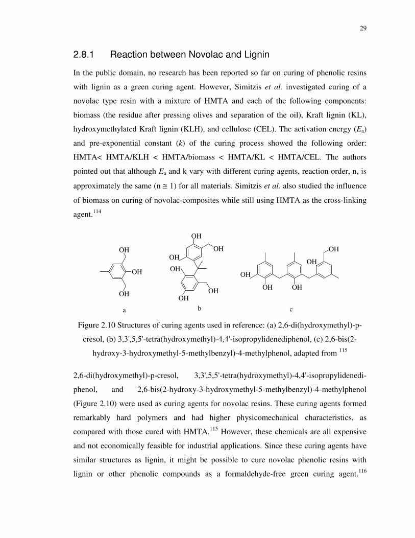
29
2.8.1 Reaction between Novolac and Lignin
In the public domain, no research has been reported so far on curing of phenolic resins
with lignin as a green curing agent. However, Simitzis et al. investigated curing of a
novolac type resin with a mixture of HMTA and each of the following components:
biomass (the residue after pressing olives and separation of the oil), Kraft lignin (KL),
hydroxymethylated Kraft lignin (KLH), and cellulose (CEL). The activation energy (Ea)
and pre-exponential constant (k) of the curing process showed the following order:
HMTA< HMTA/KLH < HMTA/biomass < HMTA/KL < HMTA/CEL. The authors
pointed out that although Ea and k vary with different curing agents, reaction order, n, is
approximately the same (n ≅ 1) for all materials. Simitzis et al. also studied the influence
of biomass on curing of novolac-composites while still using HMTA as the cross-linking
agent.114
OH
OH
OH
OHOH
OH
OH
OHOH
OH
OH
OH
OH
OH
a b c
Figure 2.10 Structures of curing agents used in reference: (a) 2,6-di(hydroxymethyl)-p-
cresol, (b) 3,3',5,5'-tetra(hydroxymethyl)-4,4'-isopropylidenediphenol, (c) 2,6-bis(2-
hydroxy-3-hydroxymethyl-5-methylbenzyl)-4-methylphenol, adapted from 115
2,6-di(hydroxymethyl)-p-cresol, 3,3',5,5'-tetra(hydroxymethyl)-4,4'-isopropylidenedi-
phenol, and 2,6-bis(2-hydroxy-3-hydroxymethyl-5-methylbenzyl)-4-methylphenol
(Figure 2.10) were used as curing agents for novolac resins. These curing agents formed
remarkably hard polymers and had higher physicomechanical characteristics, as
compared with those cured with HMTA.115 However, these chemicals are all expensive
and not economically feasible for industrial applications. Since these curing agents have
similar structures as lignin, it might be possible to cure novolac phenolic resins with
lignin or other phenolic compounds as a formaldehyde-free green curing agent.116

30
Organosolv lignin (OL, Figure 2.11), obtained from wood or other lignocellulosic
materials by extraction with an organic solvent117 may perform as a curing agent better
than Kraft lignin (KL, Figure 2.12) due to the lower molecular weight for OL. However,
there is very few research reported on curing of phenolic resins using lignin as a
hardener. Some research work in this regard is thus of great interest from the standpoints
of both development green curing agent and valorization of lignin.
Figure 2.11 Structure of organosolv lignin (OL)
Figure 2.12 A structural model of a kraft lignin fragment, adapted from 118

31
2.8.2 Reaction between Novolac and Epoxy
Due to the concerns of formaldehyde emission from the HMTA-cured novolac, it is
necessary to find an alternative to HMTA as a curing agent for novolac phenolic resins.
Epoxides have high reactivity towards a variety of chemicals, either nucleophilic or
electrophilic. Curing reactions of epoxy involve the epoxies' ring opening (forming a
secondary alcohol) followed by reactions with other species to form additive products.
Researchers have confirmed that the secondary alcohols formed could easily react with
the epoxy group by the base-catalyzed addition.119 Gagnebien et al. used bisphenol A and
glycidyl ethers as models of phenol and epoxy, respectively. The branching reaction was
initiated by the association of free amines with secondary hydroxyl groups, forming an
amino-alcohol that forms branched species with the epoxy dipole. In addition to the
hydroxyetherification reactions, protonation between phenol and epoxy was confirmed120
Alevey investigated reactions of epoxy compounds with active hydrogen compounds,
leading to epoxide-generated secondary alcohol.121 Burchard et al. described the
branching or polyaddition reaction of bisphenol A with the diglycidyl ether. When an
epoxide group reacts with a secondary hydroxyl group, a new secondary hydroxyl group
is created.122 Epoxy-phenol blends were cured when they were modified by acidic
primary octadecylamine using triphenephosphine (TPP) as a catalyst.123
Hsieh et al. studied cure kinetics of epoxy-novolac molding. Despite the fact that the
reaction mechanism was not mentioned, they demonstrated a way of curing novolac with
epoxy.124 Phenol novolac was applied as an epoxy hardener, by mixing with acetone. The
solvent was removed under vacuum after the completion of homogeneity. The mixture of
epoxy and novolac was cured under 150 oC overnight in air and was post-cured for one
hour at 220 oC under vacuum. Fully cured epoxy plaque was polished into compact
tension, tensile and three-point bend specimens.125 Novolac can be analogously cross-
linked with epoxy instead of HMTA to prepare void-free phenolic networks.126 It has
been pointed out that difunctional and multifunctional epoxy reagents can generate
crosslinking networks. The frequently used reagents were epoxidized novolac derived
from novolac oligomers and excessive epichlorohydrin. In general, the reaction of
novolac hydroxyl groups and epoxides is catalyzed by a base, such as

32
triphenylphosphine, or an acid. As shown in Scheme 2.4, the first step is the generation of
a zwitterion formed by the attack of triphenylphosphine to the epoxide. Phenoxide anions
and secondary alcohols are formed by proton transfer from phenolic hydroxyl to
zwitterions. The following step is the reaction between the phenoxide anion and either an
electrophilic carbon next to the phosphorus regenerating triphenylphosphine, or an epoxy
followed by ring opening with proton transfer to regenerate phenoxide anion. In this case,
the phenolate anion is the reactive species for cross-linkage. This reaction mechanism is
commonly accepted by most of the researchers.127
Scheme 2.4 Mechanism for the triphenylphosphine catalyzed phenol/epoxy reaction,
adapted from 58
Prepared by the reaction between cardanol-based novolac resin and epichlorohydrin in
basic medium, cardanol-based epoxidized novolac resin further reacted with methacrylic
acid in the presence of triphenylphosphine catalyst at 90 oC.128,129 Biphenyl epoxy resin
was reported to be cured by phenolic novolac with 1:1 weight ratio of epoxy to phenolic
group. The reaction rate was expressed as a function of catalyst concentrations and curing
temperatures.130 The frequent use of polyphenol materials in most of the applications is a
result of their ability to generate cured epoxy resins with high glass transition
temperatures. To some extent, secondary alcohols also reacted with the epoxy (Scheme
2.5).131 Curing of a bisphenol-A type epoxy resin and a phenolic novolac resin was also
studied and believed to proceed with an autocatalytic mechanism.132,133

33
Curing novolac resins with epoxy resins exhibits many advantages, e.g., the curing is
realized at moderate reaction temperatures, and the cured materials are free of volatile
compounds and voids.
Scheme 2.5 Reaction between polyphenol/alcohol and epoxy, adapted from 131
2.9 Production of Bio-phenols for Bio-Phenolic Resins
Bio-oil is a multi-component mixture of different types of molecules derived by
thermochemical conversions of biomass such as pyrolysis, and solvolytic/hydrothermal
liquefaction.134 Pyrolysis is the thermal degradation of biomass by heating under the
absence of oxygen to obtain charcoal, bio-oil and gas. The proportion of different
products depends on reaction conditions and feedstock properties.135-137
Solvolytic/hydrothermal liquefaction is a thermochemical treatment of biomass in
solvents with or without catalysts at lower temperatures but higher pressure than
pyrolysis. Comparison of pyrolysis and liquefaction is demonstrated in Table 2.1.
Table 2.1 Comparison of pyrolysis and solvolytic/hydrothermal of biomass138,139
Process Solvent Temperature Pressure Catalyst Targeted Products
Pyrolysis No 400-1000°C 1-20 bar No Oil, gas, and
char Solvolytic/hydrothermal
Liquefaction Yes 150-420°C
1-240 bar
Yes or No
Oil
Direct liquefaction of lignocellulosic materials in a suitable organic solvent is known as
solvolytic liquefaction which may be more advantageous than the pyrolysis processes
with respect to energy efficiency and the quality of the oily products. As such, the
34
solvolytic liquefaction technologies of lignocellulosic materials have attracted increasing
interests for the production of bio-phenol precursors for the synthesis of bio-based
phenolic resins and heavy oils (bio-crude) for bio-fuel production. Solvolytic liquefaction
of biomass in an alcohol (e.g., methanol, ethanol etc.) has lower critical temperatures and
pressures than water. Thus, they can offer mild conditions for biomass liquefaction. In
addition, these alcohols are expected to dissolve relatively high molecular weight
products from biomass owing to their low dielectric constants compared to that of
water.140 As such, hot press alcohols were widely applied in direct liquefaction of
biomass for chemicals such as vanillin, phenols, aldehydes and acetic acids. Compared
with subcritical conditions, supercritical conditions seem to be more effective in
degrading woody biomass.
In addition to monohydric alcohols,141 polyhydric alcohols such as ethylene glycol,
propylene glycol,142 and glycerol/diethylene glycol cosolvents,143 as well as mixture of
poly (propylene glycol) (PPG) and glycerol were found to be effective for direct
liquefaction of woody biomass. Bio-oil obtained from biomass liquefaction in polyhydric
alcohols showed great potential in PF resins synthesis. Kunaver et al. found that the
addition of 50% bio-oil produced from spruce wood liquefaction in glycerol/diethylene
(4:1, w/w) with the catalysis of p-toluenesulfonic acid for the condensation reaction with
melamine-formaldehyde or melamine-urea-formaldehyde resins produced resins meeting
the European standard for particleboards with reduced formaldehyde emission by 40%
and decreased pressing temperatures by 20 °C.143 Cheng et al. achieved high conversion
of biomass (95%) and bio-oil yield (65wt %) in liquefaction of woody biomass in hot-
compressed alcohol-water.144 Xu's group has achieved lots of success in substituting
phenol at a very high phenol substitution ratio (up to 75 wt%) with bio-oil derived from
woody biomass or bark via solvolytic/hydrothermal liquefaction to produce bio-based PF
resole.145
Fast pyrolysis of biomass is a thermal decomposition process through rapid heating of the
feedstock to a high temperature (400-1000 °C) in the absence of oxygen. This process
results in three main products, e.g., char, liquid bio-oil (at a yield of 40-60%), and gas.146
Bio-oil is obtained after condensation of the vapors using condensers. The bio-oil product

35
has the potential to be used as reactive chemicals and fuel. 147 One advantage of the
pyrolysis process is that it can produce an oil product of a low molecular weight. Typical
chemicals in a wood-derived bio-oil include phenolics (e.g., phenol, guaiacol, vanillin
and syringol), carbohydrate fragments (e.g., polyols and levoglucosan), organic acids,
aldehydes, and a host of oligomeric products from lignin. Pyrolysis technology has
demonstrated its potential for producing chemicals including vanillin and bio-
phenols.148,149 Pyrolysis oils contain abundant phenols, cresols, ethyl phenols, xylenols
and trimethylphenols. The phenolic-rich components were extracted from fast pyrolysis
oil and used to replace phenol in bio-based PF adhesives.150 The chemical reactivity and
molecular architecture of phenolic components affected the performance of bio-oil based
PF resin, and the study showed that a phenol substitution ratio of 25 wt% produced a bio-
PF (or simply BPF) resin of best properties.
Roy et al. invented a process for producing PF resol resins from phenolic-rich pyrolysis
oil from lignocellulosic materials.151 Chun et al. invented ways of synthesizing novolac
and resole varieties from fractionated pyrolysis oils (separating the phenolic and neutral
fractions from the oils). Wood panels were produced by using the bio-oil based novolac
or resole resins as adhesives. Interestingly, some aldehyde components in the neutral
faction of the bio-oils were also used to substitute formaldehyde during BPF resin
synthesis.152-154
Himmelblau produced BPF resin using fast pyrolysis oils as bio-phenols without any
separation.155 It should be noted that the pyrolysis process was performed with 5% of
stoichiometric combustion amount of air, which is close to the standard pyrolysis. The
pyrolysis oils were found to contain about 40 compounds that have two positions
available for methylene linkages in synthesizing the BPF resin. Up to 50% of phenol
could be substituted by pyrolysis oils and the yielded resins presented comparable
strength and water resistance to commercial petroleum-based PF resins.
Researchers from Ensyn had made efforts in preparing natural resin precursors by the fast
pyrolysis process.156-158 These obtained natural resin precursors comprised 30-80 wt%

36
phenolic compounds, which could be used to substitute up to 60% of phenol in the
synthesis of bio-based phenolic resole/novoalc resins.
Mourant et al. performed pyrolysis of softwood and resin synthesis by using pyrolytic oil
as a phenol substitute. The cross-linking activation energy was evaluated by rheological
study.159 Together with phenol and formaldehyde, phenolic-rich oils generated by
vacuum pyrolysis of bark residues were formulated into BPF resoles as wood adhesives.
Standard boards were prepared with BPF resoles with different levels of phenol
replacement. Those panels with BPF resin from 25 and 50 wt% of the phenol
replacement presented comparable mechanical properties to those with commercial PF
resin.135
Charcoalization is a slow pyrolysis process generating wood tars as one of the by-
products. Similar to pyrolysis oil, lignin originated wood tar contains complex aromatic
compounds including phenol derivatives that are a potential source of bio-phenol. Resole
type resins were prepared from wood tar, phenol and formaldehyde, with phenol
substitution levels as high as 60%.160 In fact, many research endeavors have been made
on the utilization of lignin as an alternative of phenol in synthesizing lignin-modified
phenol-formaldehyde (LPF) resins. However, lignin has less reactive sites than phenol to
react with aldehydes. Thus, the lignin shall be modified by phenolation,161,162
methylolation,163 and demethylation164 to obtain more reactive functional groups, and
liquefied or de-polymerized into depolymerized lignin of a lower molecular weight and
higher reactivity.165 However, production of formaldehyde-free bio-phenolic resin with
bio-phenol to substitute petroleum-based phenol has not been reported to date.
2.10 Conclusions and Recommendations
(1) As formaldehyde is regarded as a carcinogenic compound, it is imperative to reduce
and eliminate formaldehyde use in future manufacture of phenolic resins.
(2) Lignin and its derivatives are of phenolic nature, so they are promising sources of bio-
phenols.

37
(3) Hydroxymethylfurfural (HMF) can be produced from catalytic conversion of
inexpensive glucose and cellulose.
(4) Reacting phenol and HMF in-situ derived from glucose can produce phenol-HMF
(PHMF) resins - novel formaldehyde-free novolac phenolic resins.
(5) Bio-phenolic compounds from woody biomass or lignin may react with HMF to
produce bio-phenol HMF (BPHMF) resins.
(6) HMTA along with other novel non-HMTA curing agents such as lignin or epoxy resin
may be effective for cross-linking of PHMF and BPHMF novolac resins.
(7) Industrial applications of PHMF and BPHMF resins need to be demonstrated in future
works.

38
References
1. Gardziella A, Pilato LA, Knop A. Phenolic resins: Chemistry, applications,
standardization, safety and ecology. (2nd edition). Heidelberg: Springer, 2000.
2. SRI C. World Petrochemical (WP) report on PF Resins. 2011.
3. Wolfgang Hesse JL. Phenolic Resins. In: Ullmann's Encyclopedia of Industrial Chemistry. Weinheim: Wiley-VCH, 2002.
4. Gardziella A, Kwasniok A, Adolphs P, Wetzig R. Novel molding materials. US Patent. 1991;US5043365.
5. Kalinowski PW. Grinding wheel. US Patent. 1990;4913708.
6. Kim SJ, Kim KS, Jang H. Optimization of manufacturing parameters for a brake lining using Taguchi method. J Mater Process Technol. 2003;136:202-208.
7. Giller A. Rubber mixtures reinforced by phenol novolac resins and process for preparing phenol novolac resins suitable therefor. US Patent. 1971;US3586735.
8. Haley NF, Corbiere SL. Radiation-sensitive composition containing a resole resin and a novolac resin and use thereof in lithographic printing plates Haley. US Patent. 1994;US5340699.
9. World Health Organization. Environmental Health Criteria 89: formaldehyde. IPCS. 1989:219.
10. Kowatsch S. Formaldehyde. In: Pilato L . Phenolic Resins: A Century of Progress. Berlin: Springer, 2010:25-40.
11. US E. Extremely Hazardous Substances: Superfund Chemical Profiles. Norwich, NY: William Andrew Publishing, 1988.
12. Hahnenstein I, Hasse H, Kreiter CG, Maurer G. 1H- and 13C-NMR Spectroscopic Study of Chemical Equilibria in Solutions of Formaldehyde in Water, Deuterium Oxide, and Methanol. Ind Eng Chem Res. 1994;33:1022-1029.
13. Appelman LM, Woutersen RA, Zwart A, Falke HE, Feron VJ. One‐year inhalation toxicity study of formaldehyde in male rats with a damaged or undamaged nasal mucosa. J Appl Toxicol. 1988;8:85-90.
14. Sellakumar AR, Snyder CA, Solomon JJ, Albert RE. Carcinogenicity of formaldehyde and hydrogen chloride in rats. Toxicol Appl Pharmacol. 1985;81:401-406.
15. Hauptmann M, Lubin JH, Stewart PA, Hayes RB, Blair A. Mortality from solid cancers among workers in formaldehyde industries. Am J Epidemiol. 2004;159:1117-1130.

39
16. Arts J, Rennen M, Heer C. Inhaled formaldehyde: evaluation of sensory irritation in relation to carcinogenicity. Regul Toxicol Pharmacol. 2006;44:144-160.
17. Klass DL. Biomass for renewable energy, fuels, and chemicals. (3rd edition). San Diego, California: Academic press, 1998.
18. Ragauskas AJ, Williams CK, Davison BH, Britovsek G, Cairney J, Eckert CA, Frederick WJ, Hallett JP, Leak DJ, Liotta CL. The path forward for biofuels and biomaterials. Science. 2006;311:484-489.
19. Babu SP. Observations on the current status of biomass gasification. Biomass
Bioenergy. 2005;29:I-XII.
20. Bridgwater AV, Peacocke GVC. Fast pyrolysis processes for biomass. Renew Sust
Energ Rev. 2000;4:1-73.
21. Feng S, Cheng S, Yuan Z, Leitch M, Xu CC. Valorization of bark for chemicals and materials: A review. Renew Sust Energ Rev. 2013;26:560-578.
22. Lynd LR, Weimer PJ, van Zyl WH, Pretorius IS. Microbial cellulose utilization: fundamentals and biotechnology. Microbiol Mol Biol Rev. 2002;66:506-577.
23. Rostrup-Nielsen JR. Syngas in perspective. Catal Today. 2002;71:243-247.
24. Furimsky E. Catalytic hydrodeoxygenation. Appl Catal A-Gen. 2000;199:147-190.
25. Lynd LR, Cushman JH, Nichols RJ, Wyman CE. Fuel ethanol from cellulosic biomass. Science. 1991;251:1318-1323.
26. Tu Y, Chen Y. Effects of alkaline-earth oxide additives on silica-supported copper catalysts in ethanol dehydrogenation. Ind Eng Chem Res. 1998;37:2618-2622.
27. Chheda JN, Huber GW, Dumesic JA. Liquid‐Phase Catalytic Processing of Biomass‐Derived Oxygenated Hydrocarbons to Fuels and Chemicals. Angew Chem Int
Ed. 2007;46:7164-7183.
28. Huber GW, Dumesic JA. An overview of aqueous-phase catalytic processes for production of hydrogen and alkanes in a biorefinery. Catal Today. 2006;111:119-132.
29. Huber GW, Iborra S, Corma A. Synthesis of transportation fuels from biomass: chemistry, catalysts, and engineering. Chem Rev. 2006;106:4044-4098.
30. Van Dyne DL, Blase MG, Clements LD. A strategy for returning agriculture and rural America to long-term full employment using biomass refineries. Perspectives on new
crops and new uses.ASHS Press, Alexandria, Va. 1999:114-123.
31. Kamm B, Kamm M. Principles of biorefineries. Appl Microbiol Biotechnol. 2004;64:137-145.

40
32. Corma A, Iborra S, Velty A. Chemical routes for the transformation of biomass into chemicals. Chemical Reviews-Columbus. 2007;107:2411-2502.
33. Lichtenthaler FW. Unsaturated O-and N-heterocycles from carbohydrate feedstocks. Acc Chem Res. 2002;35:728-737.
34. Perlack RD, Wright LL, Turhollow AF, Graham RL, Stokes BJ, Erbach DC. Biomass as Feedstock for a bioenergy and bioproducts industry: the technical feasibility of a billion-ton annual supply. U S Department of Energy. 2005;DE-AC05-00OR22725:1-60.
35. Tejado A, Pena C, Labidi J, Echeverria JM, Mondragon I. Physico-chemical characterization of lignins from different sources for use in phenol–formaldehyde resin synthesis. Bioresour Technol. 2007;98:1655-1663.
36. Gosselink RJA, De Jong E, Guran B, Abächerli A. Co-ordination network for lignin—standardisation, production and applications adapted to market requirements (EUROLIGNIN). Ind Crop Prod. 2004;20:121-129.
37. Holladay J, Bozell J, White J, Johnson D. Top value-added chemicals from biomass. Volume II–Results of Screening for Potential Candidates from Biorefinery Lignin, Report
prepared by members of NREL, PNNL and University of Tennessee. 2007.
38. McLaren J. The technology roadmap for plant/crop-based renewable resources 2020. Renewable Vision 2020. 1999.
39. Raquez JM, Deléglise M, Lacrampe MF, Krawczak P. Thermosetting (bio) materials derived from renewable resources: A critical review. Progress in Polymer Science. 2010;35:487-509.
40. Nair CP. Advances in addition-cure phenolic resins. Prog Polym Sci. 2004;29:401-498.
41. Ghosh NN, Kiskan B, Yagci Y. Polybenzoxazines—new high performance thermosetting resins: synthesis and properties. Prog Polym Sci. 2007;32:1344-1391.
42. Lin SY, Lebo SE. Lignin. In: . Kirk-Othmer encyclopedia of chemical technology. Hoboken, NJ, United States of America: John Wiley & Sons, Inc., 1995.
43. Sena-Martins G, Almeida-Vara E, Duarte JC. Eco-friendly new products from enzymatically modified industrial lignins. Ind Crop Prod. 2008;27:189-195.
44. Tejado A, Kortaberria G, Pena C, Blanco M, Labidi J, Echeverria J, Mondragon I. Lignins for phenol replacement in novolac‐type phenolic formulations. II. Flexural and compressive mechanical properties. J Appl Polym Sci. 2008;107:159-165.
45. Lora JH, Glasser WG. Recent industrial applications of lignin: a sustainable alternative to nonrenewable materials. J Polym Environ. 2002;10:39-48.
41
46. Sellers Jr T, Kim MG, Miller GD, Haupt RA, Strickland RC. Comparison of strandboards made with phenol-formaldehyde resin and resins modified with TVA acid-hydrolysis lignin. For Prod J. 1994;44:63-68.
47. Shimizu K, Sudo K, Ono H, Ishihara M, Fujii T, Hishiyama S. Integrated process for total utilization of wood components by steam-explosion pretreatment. Biomass
Bioenergy. 1998;14:195-203.
48. Cetin NS, Özmen N. Use of organosolv lignin in phenol–formaldehyde resins for particleboard production: I. Organosolv lignin modified resins. Int J Adhes Adhes. 2002;22:477-480.
49. Alonso MV, Rodríguez JJ, Oliet M, Rodríguez F, Garcia J, Gilarranz MA. Characterization and structural modification of ammonic lignosulfonate by methylolation. J Appl Polym Sci. 2001;82:2661-2668.
50. Pérez J, Oliet M, Alonso M, Rodríguez F. Cure kinetics of lignin-novolac resins studied by isoconversional methods. Thermochimica Acta. 2009;487:39-42.
51. Rautio P, Bergvall UA, Karonen M, Salminen J. Bitter problems in ecological feeding experiments: Commercial tannin preparations and common methods for tannin quantifications. Biochem Syst Ecol. 2007;35:257-262.
52. Martinez S. Inhibitory mechanism of mimosa tannin using molecular modeling and substitutional adsorption isotherms. Mater Chem Phys. 2003;77:97-102.
53. Pizzi A, Meikleham N, Stephanou A. Induced accelerated autocondensation of polyflavonoid tannins for phenolic polycondensates. II. Cellulose effect and application. J Appl Polym Sci. 1995;55:929-933.
54. Pena C, Larranaga M, Gabilondo N, Tejado A, Echeverria JM, Mondragon I. Synthesis and characterization of phenolic novolacs modified by chestnut and mimosa tannin extracts. J Appl Polym Sci. 2006;100:4412-4419.
55. Kim S, Kim H. Curing behavior and viscoelastic properties of pine and wattle tannin-based adhesives studied by dynamic mechanical thermal analysis and FT-IR-ATR spectroscopy. J Adhes Sci Technol. 2003;17:1369-1383.
56. Sowunmi S, Ebewele RO, Peters O, Conner AH. Differential scanning calorimetry of hydrolysed mangrove tannin. Polym Int. 2000;49:574-578.
57. Garro–Galvez JM, Riedl B. Pyrogallol–formaldehyde thermosetting adhesives. J Appl
Polym Sci. 1997;65:399-408.
58. Pizzi A, Mittal KL. Phenolic resins adhesives. In: Pizzi A MK . Handbook of Adhesive Technology. New York: Marcel Dekker, 2003:577-582.

42
59. Trosa A, Pizzi A. A no-aldehyde emission hardener for tannin-based wood adhesives for exterior panels. Eur J Wood Wood Prod. 2001;59:266-271.
60. Yadav R, Devi A, Tripathi G, Srivastava D. Optimization of the process variables for the synthesis of cardanol-based novolac-type phenolic resin using response surface methodology. Eur Polym J. 2007;43:3531-3537.
61. Devi A, Srivastava D. Cardanol‐based novolac‐type phenolic resins. I. A kinetic approach. J Appl Polym Sci. 2006;102:2730-2737.
62. Campaner P, D'Amico D, Longo L, Stifani C, Tarzia A. Cardanol‐based novolac resins as curing agents of epoxy resins. J Appl Polym Sci. 2009;114:3585-3591.
63. Cardona F, Kin‐Tak AL, Fedrigo J. Novel phenolic resins with improved mechanical and toughness properties. J Appl Polym Sci. 2012;123:2131-2139.
64. Rao BS, Palanisamy A. Synthesis of bio based low temperature curable liquid epoxy, benzoxazine monomer system from cardanol: Thermal and viscoelastic properties. Eur
Polym J. 2013;49:2365-2376.
65. Yadav R, Srivastava D. Kinetics of the acid-catalyzed cardanol–formaldehyde reactions. Mater Chem Phys. 2007;106:74-81.
66. Pillai C, Prasad VS, Sudha JD, Bera SC, Menon A. Polymeric resins from renewable resources. II. Synthesis and characterization of flame‐retardant prepolymers from cardanol. J Appl Polym Sci. 1990;41:2487-2501.
67. Devi A, Srivastava D. Studies on the blends of cardanol-based epoxidized novolac type phenolic resin and carboxyl-terminated polybutadiene (CTPB), I. Mat Sci Eng A-
Struct. 2007;458:336-347.
68. da Silva Santos R, de Souza AA, De Paoli M, de Souza, Cleide Maria Leite. Cardanol–formaldehyde thermoset composites reinforced with buriti fibers: preparation and characterization. Compos Part A-Appl S. 2010;41:1123-1129.
69. Barreto ACH, Rosa DS, Fechine PBA, Mazzetto SE. Properties of sisal fibers treated by alkali solution and their application into cardanol-based biocomposites. Compos Part
A-Appl S. 2011;42:492-500.
70. Calò E, Maffezzoli A, Mele G, Martina F, Mazzetto SE, Tarzia A, Stifani C. Synthesis of a novel cardanol-based benzoxazine monomer and environmentally sustainable production of polymers and bio-composites. Green Chem. 2007;9:754-759.
71. Srivastava R, Srivastava D. Preparation and thermo-mechanical characterization of novel epoxy resins using renewable resource materials. J Polym Environ. 2014;DOI 10.1007/s10924-014-0659-6:1-11.

43
72. Patel AU, Soni SS, Patel HS. Synthesis, Characterization and Curing of o-Cresol–Furfural Resins. Int J Polym Mater. 2009;58:509-516.
73. Pizzi A, Orovan E, Cameron F. The development of weather-and boil-proof phenol-resorcinol-furfural cold-setting adhesives. European Journal of Wood and Wood
Products. 1984;42:467-472.
74. Oliveira FB, Gardrat C, Enjalbal C, Frollini E, Castellan A. Phenol–furfural resins to elaborate composites reinforced with sisal fibers—Molecular analysis of resin and properties of composites. J Appl Polym Sci. 2008;109:2291-2303.
75. Patel RD, Patel RG, Patel VS, Pearce EM. Kinetic investigation on the curing of phenol‐furfural resin by differential scanning calorimetry. J Appl Polym Sci. 1987;34:2583-2589.
76. Amaral‐Labat GA, Pizzi A, Goncalves AR, Celzard A, Rigolet S, Rocha G. Environment‐friendly soy flour‐based resins without formaldehyde. J Appl Polym Sci. 2008;108:624-632.
77. Lei H, Pizzi A, Du G. Environmentally friendly mixed tannin/lignin wood resins. J
Appl Polym Sci. 2008;107:203-209.
78. Zhao H, Holladay JE, Brown H, Zhang ZC. Metal chlorides in ionic liquid solvents convert sugars to 5-hydroxymethylfurfural. Science. 2007;316:1597-1600.
79. Kuster B. 5‐Hydroxymethylfurfural (HMF). A review focussing on its manufacture. Starch - Stärke. 1990;42:314-321.
80. Haworth WN, Jones W. 183. The conversion of sucrose into furan compounds. Part I. 5-Hydroxymethylfurfuraldehyde and some derivatives. J Chem Soc. 1944:667-670.
81. Van Dam HE, Kieboom A, Van Bekkum H. The conversion of fructose and glucose in acidic media: formation of hydroxymethylfurfural. Starch‐Stärke. 1986;38:95-101.
82. Antal MJ, Mok W, Richards GN. Kinetic-studies of the reactions of ketoses and aldoses in water at high-temperature. 1. Mechanism of formation of 5-(hydroxymethyl)-2-furaldehyde from d-fructose and sucrose. Carbohydr Res. 1990;199:91-109.
83. Yang G, Pidko E, Hensen E. Mechanism of Brønsted acid-catalyzed conversion of carbohydrates. J Catal. 2012;295:122-132.
84. Zhang J, Weitz E. An in Situ NMR Study of the Mechanism for the Catalytic Conversion of Fructose to 5-Hydroxymethylfurfural and then to Levulinic Acid Using 13C Labeled D-Fructose. ACS Catal. 2012;2:1211-1218.
85. Seri K, Sakaki T, Shibata M, Inoue Y, Ishida H. Lanthanum (III)-catalyzed degradation of cellulose at 250 C. Bioresour Technol. 2002;81:257-260.

44
86. Ståhlberg T, Fu W, Woodley JM, Riisager A. Synthesis of 5‐(Hydroxymethyl) furfural in Ionic Liquids: Paving the Way to Renewable Chemicals. ChemSusChem. 2011;4:451-458.
87. Cottier L, Descotes G. 5‐(Hydroxymethyl) furfural Syntheses and Chemical Transformations. Trends Heterocycl Chem. 1991;2:223-248.
88. Chidambaram M, Bell AT. A two-step approach for the catalytic conversion of glucose to 2, 5-dimethylfuran in ionic liquids. Green Chem. 2010;12:1253-1262.
89. Pidko EA, Degirmenci V, van Santen RA, Hensen E. Glucose activation by transient Cr2+ dimers. Angew Chem Int Ed. 2010;49:2530-2534.
90. Lima S, Neves P, Antunes MM, Pillinger M, Ignatyev N, Valente AA. Conversion of mono/di/polysaccharides into furan compounds using 1-alkyl-3-methylimidazolium ionic liquids. Appl Catal , A. 2009;363:93-99.
91. Corma A, Garcia H. Organic reactions catalyzed over solid acids. Catal Today. 1997;38:257-308.
92. Seri K, Inoue Y, Ishida H. Highly Efficient Catalytic Activity of Lanthanide (III) Ions for Conversion of Saccharides to 5-Hydroxymethyl-2-furfural in Organic Solvents. Chem
Lett. 2000;29:22-23.
93. Carlini C, Patrono P, Galletti A, Sbrana G. Heterogeneous catalysts based on vanadyl phosphate for fructose dehydration to 5-hydroxymethyl-2-furaldehyde. Appl Catal A-
Gen. 2004;275:111-118.
94. Huang R, Qi W, Su R, He Z. Integrating enzymatic and acid catalysis to convert glucose into 5-hydroxymethylfurfural. Chem Commun. 2010;46:1115-1117.
95. Shimizu K, Uozumi R, Satsuma A. Enhanced production of hydroxymethylfurfural from fructose with solid acid catalysts by simple water removal methods. Catal Commun. 2009;10:1849-1853.
96. Dee SJ, Bell AT. A Study of the Acid‐Catalyzed Hydrolysis of Cellulose Dissolved in Ionic Liquids and the Factors Influencing the Dehydration of Glucose and the Formation of Humins. ChemSusChem. 2011;4:1166-1173.
97. Chheda JN, Román-Leshkov Y, Dumesic JA. Production of 5-hydroxymethylfurfural and furfural by dehydration of biomass-derived mono-and poly-saccharides. Green
Chem. 2007;9:342-350.
98. Kuster B, S van der Baan, Hessel. The influence of the initial and catalyst concentrations on the dehydration of D-fructose. Carbohydr Res. 1977;54:165-176.
99. Musau RM, Munavu RM. The preparation of 5-hydroxymethyl-2-furaldehyde (HMF) from D-fructose in the presence of DMSO. Biomass. 1987;13:67-74.
45
100. Bicker M, Hirth J, Vogel H. Dehydration of fructose to 5-hydroxymethylfurfural in sub-and supercritical acetone. Green Chem. 2003;5:280-284.
101. Dalinyebo. Furfural Market.
102. Alibaba. Formaldehyde Price.
103. Alibaba. Dextrose Monohydrate Food grade food additves sweeteners glucose.
104. Wang M, Yuan Z, Cheng S, Leitch M, Xu CC. Synthesis of novolac‐type phenolic resins using glucose as the substitute for formaldehyde. J Appl Polym Sci. 2010;118:1191-1197.
105. Wu D, Fu R. Synthesis of organic and carbon aerogels from phenol–furfural by two-step polymerization. Micropor Mesopor Mater. 2006;96:115-120.
106. Long DH, Zhang J, Yang JH, Hu ZJ, Li TQ, Cheng G, Zhang R, Ling LC. Preparation and microstructure control of carbon aerogels produced using m-cresol mediated sol-gel polymerization of phenol and furfural. New Carbon Mater. 2008;23:165-170.
107. Li C, Zhang Z, Zhao ZK. Direct conversion of glucose and cellulose to 5-hydroxymethylfurfural in ionic liquid under microwave irradiation. Tetrahedron Lett. 2009;50:5403-5405.
108. Yuan Z, Xu CC, Cheng S, Leitch M. Catalytic conversion of glucose to 5-hydroxymethyl furfural using inexpensive co-catalysts and solvents. Carbohydr Res. 2011;346:2019-2023.
109. Lytle CA, Bertsch W, McKinley M. Determination of novolac resin thermal decomposition products by pyrolysis-gas chromatography-mass spectrometry. J Anal
Appl Pyrolysis. 1998;45:121-131.
110. Nielsen AT, Moore DW, Ogan MD, Atkins RL. Structure and chemistry of the aldehyde ammonias. 3. Formaldehyde-ammonia reaction. 1, 3, 5-Hexahydrotriazine. J
Org Chem. 1979;44:1678-1684.
111. Richmond HH, Myers GS, Wright GF. The reaction between formaldehyde and ammonia. J Am Chem Soc. 1948;70:3659-3664.
112. Pichelin F, Kamoun C, Pizzi A. Hexamine hardener behaviour: effects on wood glueing, tannin and other wood adhesives. Eur J Wood Wood Prod. 1999;57:305-317.
113. Hatfield GR, Maciel GE. Solid-state NMR study of the hexamethylenetetramine curing of phenolic resins. Macromolecules. 1987;20:608-615.
114. Simitzis J, Karagiannis K, Zoumpoulakis L. Influence of biomass on the curing of novolac-composites. Eur Polym J. 1996;32:857-863.

46
115. Sergeev VA, Shitikov VK, Nechaev AI, Chizhova NV, Kudryavsteva NN. Hydroxymethyl derivatives of phenols as curing agents for novolacs. Polym Sci Ser B. 1995;37:273-276.
116. Grenier-Loustalot M, Larroque S, Grenier P. Phenolic resins: 4. Self-condensation of methylolphenols in formaldehyde-free media. Polymer. 1996;37:955-964.
117. Aden A., Bozell J., Holladay J, White J, Manheim A. Top value-added chemicals from biomass. DOE Report PNNL-16983. Available at:
http://chembioprocess.pnl.gov/staff/staff_info.asp (Accessed April 20, 2014)). 2004;PNNL-14808:1-66.
118. Sarkanen KV, Ludwig CH. Lignins: occurrence, formation, structure and reactions. New York: Wiley Interscience, 1971.
119. Batzer H, Zahir SA. Studies in the molecular weight distribution of epoxide resins. II. Chain branching in epoxide resins. J Appl Polym Sci. 1975;19:601-607.
120. Gagnebien D, Madec P, Marechal E. Synthesis of poly (sulphone-b-siloxane) s—I. Model study of the epoxy-phenol reaction in the melt. Eur Polym J. 1985;21:273-287.
121. Alvey FB. Selectivity of the epoxide phenol reaction. J Appl Polym Sci. 1969;13:1473-1486.
122. Burchard W, Bantle S, Zahir SA. Branching in high molecular weight polyhydroxyethers based on bisphenol A. Macromol Chem Phys. 1981;182:145-163.
123. Liu D, Shi Z, Matsunaga M, Yin J. DSC investigation of the hindered effect on curing behavior for epoxy–phenol/MMT nanocomposites based on the acidic octadecylamine modifier. Polymer. 2006;47:2918-2927.
124. Hsieh T, Su A. Cure kinetics of an epoxy‐novolac molding compound. J Appl Polym
Sci. 1990;41:1271-1280.
125. Dean JME. Structure-property relationships in block copolymer modified epoxy resins with novel morphologies. Ph D Thesis, University of Minnesota. 2002:1-236.
126. Lin-Gibson S. Cresol Novolac/Epoxy Networks: Synthesis, Properties, and Processability. Doctoral Dissertations, Virginia Polytechnic Institute and State
University. 2001:1-249.
127. Ren S, Lan Y, Zhen Y, Ling Y, Lu M. Curing reaction characteristics and phase behaviors of biphenol type epoxy resins with phenol novolac resins. Thermochim Acta. 2006;440:60-67.
128. Sultania M, Rai J, Srivastava D. Studies on the synthesis and curing of epoxidized novolac vinyl ester resin from renewable resource material. Eur Polym J. 2010;46:2019-2032.

47
129. Yadav R, Awasthi P, Srivastava D. Studies on synthesis of modified epoxidized novolac resin from renewable resource material for application in surface coating. J Appl
Polym Sci. 2009;114:1471-1484.
130. Han S, Yoon HG, Suh KS, Kim WG, Moon TJ. Cure kinetics of biphenyl epoxy‐phenol novolac resin system using triphenylphosphine as catalyst. J Polym Sci A
Polym Chem. 1999;37:713-720.
131. Levchik SV, Weil ED. Thermal decomposition, combustion and flame‐retardancy of epoxy resins—a review of the recent literature. Polym Int. 2004;53:1901-1929.
132. Brunelle DJ, Evans TL. Contemporary Topics in Polymer Science. In: Salamone JC, Riffle JS. New York: Plenum Press, 1992:108.
133. Park SJ, Seo MK, Lee JR. Isothermal cure kinetics of epoxy/phenol‐novolac resin blend system initiated by cationic latent thermal catalyst. J Polym Sci , Part A: Polym
Chem. 2000;38:2945-2956.
134. Effendi A, Gerhauser H, Bridgwater AV. Production of renewable phenolic resins by thermochemical conversion of biomass: A review. Renew Sust Energ Rev. 2008;12:2092-2116.
135. Amen-Chen C, Riedl B, Wang XM, Roy C. Softwood bark pyrolysis oil-PF resols. Part 1. Resin synthesis and OSB mechanical properties. Holzforschung. 2002;56:167-175.
136. Amen-Chen C, Riedl B, Roy C. Softwood bark pyrolysis oil-PF resols. Part 2. Thermal analysis by DSC and TG. Holzforschung. 2002;56:273-280.
137. Amen-Chen C, Riedl B, Wang XM, Roy C. Softwood bark pyrolysis oil-PF resols. Part 3. Use of propylene carbonate as resin cure accelerator. Holzforschung. 2002;56:281-288.
138. Demirbaş A. Mechanisms of liquefaction and pyrolysis reactions of biomass. Energy
Convers Manage. 2000;41:633-646.
139. Behrendt F, Neubauer Y, Oevermann M, Wilmes B, Zobel N. Direct liquefaction of biomass. Chem Eng Technol. 2008;31:667-677.
140. Yamazaki J, Minami E, Saka S. Liquefaction of beech wood in various supercritical alcohols. J Wood Sci. 2006;52:527-532.
141. Minami E, Kawamoto H, Saka S. Reaction behavior of lignin in supercritical methanol as studied with lignin model compounds. J Wood Sci. 2003;49:158-165.
142. Rezzoug SA, Capart R. Assessment of wood liquefaction in acidified ethylene glycol using experimental design methodology. Energy Convers Manage. 2003;44:781-792.

48
143. Kunaver M, Medved S, Čuk N, Jasiukaityt÷ E, Poljanšek I, Strnad T. Application of liquefied wood as a new particle board adhesive system. Bioresour Technol. 2010;101:1361-1368.
144. Cheng S, D’cruz I, Wang M, Leitch M, Xu C. Highly Efficient Liquefaction of Woody Biomass in Hot-Compressed Alcohol− Water Co-solvents. Energy Fuels. 2010;24:4659-4667.
145. Cheng S, D'Cruz I, Yuan Z, Wang M, Anderson M, Leitch M, Xu CC. Use of biocrude derived from woody biomass to substitute phenol at a high‐substitution level for the production of biobased phenolic resol resins. J Appl Polym Sci. 2011;121:2743-2751.
146. Maschio G, Koufopanos C, Lucchesi A. Pyrolysis, a promising route for biomass utilization. Bioresour Technol. 1992;42:219-231.
147. Onay O, Koçkar OM. Pyrolysis of rapeseed in a free fall reactor for production of bio-oil. Fuel. 2006;85:1921-1928.
148. Lira CS, Berruti FM, Palmisano P, Berruti F, Briens C, Pécora AA. Fast pyrolysis of Amazon tucumã (Astrocaryum aculeatum) seeds in a bubbling fluidized bed reactor. J
Anal Appl Pyrolysis. 2013;99:23-31.
149. Xu C, Lad N. Production of heavy oils with high caloric values by direct liquefaction of woody biomass in sub/near-critical water. Energy Fuels. 2007;22:635-642.
150. Kelley SS, Wang X, Myers MD, Johnson DK, Scahill JW. Use of biomass pyrolysis oils for preparation of modified phenol formaldehyde resins. In: Bridgwater V, Boocock B. Developments in Thermochemical Biomass Conversion. London: Springer, 1997:557-572.
151. Roy C, Lu X, Pakdel H. Process for the production of phenolic-rich pyrolysis oils for use in making phenol-formaldehyde resole resins. US Patent. 2000;6143856.
152. Black SK, Chum HL, Diebold JP, Kreibich RE. Phenolic compounds containing neutral fractions extract and products derived therefrom from fractionated fast-pyrolysis oils. US Patent. 1993;5223601.
153. Black SK, Chum HL, Diebold JP, Kreibich RE. Resole resin products derived from fractionated organic and aqueous condensates made by fast-pyrolysis of biomass materials. US Patent. 1993;5235021.
154. Chum HL, Kreibich RE. Process for preparing phenolic formaldehyde resole resin products derived from fractionated fast-pyrolysis oils. US Patent. 1992;5091499.
155. Himmelblau A. Method and apparatus for producing water-soluble resin and resin product made by that method. US Patent. 1991;5034498.

49
156. Giroux R, Freel B, Graham R. Natural resin formulations. US Patent. 2001;6326461.
157. Freel B, Graham RG, Giroux R. Natural resin formulations. US Patent. 2005;6844420.
158. Freel BA, Graham RG. Method and apparatus for a circulating bed transport fast pyrolysis reactor system. US Patent. 1998;5792340.
159. Mourant D, Riedl B, Rodrigue D, Yang D, Roy C. Phenol–formaldehyde–pyrolytic oil resins for wood preservation: A rheological study. J Appl Polym Sci. 2007;106:1087-1094.
160. Lu K, Wu L. Substitution of phenol in phenol-formaldehyde (PF) resins by wood tar for plywood adhesives. Holzforschung. 2013;67:413-419.
161. Alonso MV, Oliet M, Rodrıguez F, Garcıa J, Gilarranz M, Rodrıguez J. Modification of ammonium lignosulfonate by phenolation for use in phenolic resins. Bioresour Technol. 2005;96:1013-1018.
162. Lee S, Teramoto Y, Shiraishi N. Acid‐catalyzed liquefaction of waste paper in the presence of phenol and its application to Novolak‐type phenolic resin. J Appl Polym Sci. 2002;83:1473-1481.
163. Alonso MV, Oliet M, Pérez JM, Rodrıguez F, Echeverrıa J. Determination of curing kinetic parameters of lignin–phenol–formaldehyde resol resins by several dynamic differential scanning calorimetry methods. Thermochim Acta. 2004;419:161-167.
164. Ferhan M, Yan N, Sain M. A New Method for Demethylation of Lignin from Woody Biomass using Biophysical Methods. J Chem Eng Process Technol. 2013;4:160.
165. Cheng S, Yuan Z, Anderson M, Anderson M, Xu CC. Highly efficient de-polymerization of organosolv lignin using a catalytic hydrothermal process and production of phenolic resins/adhesives with the depolymerized lignin as a substitute for phenol at a high substitution ratio. Ind Crop Prod. 2013;44:315-322.

50
Chapter 3
3 Kinetics and Mechanism of Phenol-glucose Novolac Resin Cured with an Epoxy
3.1 Introduction
Due to depletion of the petroleum resource and the desire to reduce the society’s
dependence on crude oil, production of green chemicals and fuels from renewable
resources has attracted intensive interest all over the world.1,2 Various intermediates from
biomass components (cellulose, hemicellulose and lignin) can be transformed into
potentially useful products.3 As the main biomass component, cellulose has a great
potential for sustainable production of chemicals and fuels. Hydrolysis of cellulose into
glucose has attracted intensive research interests because D-glucose is an ideal platform
chemical for various chemicals, fuels, foods and medicines.2-5 Onda, et al. have realized
the conversion of cellulose to glucose with remarkable selectivity with solid acid
catalysts.6
During the last century, phenol-formaldehyde (PF) resins, produced from
polycondensation of phenol and formaldehyde, played an important role as adhesives and
engineering plastics. Formaldehyde, usually used as aqueous solution 37-50 wt. %, is
essential for their preparation. However, formaldehyde is hazardous and carcinogenic.
The vapor of formaldehyde is irritating to eyes and respiratory tract and can bring serious
health risk if its concentration exceeds 1 ppm.7 Moreover, formaldehyde has an effect of
negative mutagenesis in bacterial or mammalian cells even for the whole animal systems.
Since the discovery of the carcinogenic effect of formaldehyde in 1980s, producing
formaldehyde-free wood composites has been an urgent task due to the unavoidable
formaldehyde emission from PF resin-based wood adhesive. An international regulation
of limiting formaldehyde emission, “Formaldehyde standards for composite wood
products act” was signed into law on July 7, 2010.
Currently, considerable research has focused on total or partial substitute of petroleum-
based phenol with lignocellulosic biomass such as liquefied pine bark,8 lignin,9,10

51
tannin,11,12 and cardanol,13 etc. Glucose as an aldehyde is environmental benign and
abundantly available, and may substitute hazardous formaldehyde for the synthesis of
phenolic resin. Xu’s group reported their latest progress in this area, in which glucose
was applied to synthesize novel novolac type phenolic resins, which is curable with
hexamethylene tetramine (HMTA).14 During the formation of novolac resin, methylene
bridges between benzene rings formed. There is at least one ortho- or para- position left
in phenol ring which can form new methylene bridges by reacting with additional
formaldehyde generated by decomposition of HMTA at an elevated temperature.15
However, HMTA, the most common compound used for curing of novolac type phenolic
resins is a condensation product of ammonia and formaldehyde, and is among the
restricted chemicals due to its emission of formaldehyde in applications. Thus, it is of
great interest to realize replacement of formaldehyde and HMTA in curing of novolac
resins. This study is to replace HMTA with a bis-phenol-A type epoxy for the curing of
the phenol-glucose novolac resins. Epoxides have a high reactivity towards a variety of
chemicals, either nucleophilic or electrophilic. Generally curing reaction of epoxy
involves the epoxies' ring opening followed by reaction with other species to form
additive products.16 Novolac resins can be cross-linked with epoxy instead of HMTA to
prepare void free phenolic networks.17 It has been pointed out that difunctional and
multifunctional epoxy regents can generate networks. Cardanol-based epoxidized
novolac resin was prepared by the reaction between cardanol-based novolac resin and
epichlorohydrin in basic medium, and it could further react with methacrylic acid in the
presence of triphenylphosphine at 90oC.18,19 Biphenyl epoxy resin was reported to be
cured by phenol novolac with 1:1 weight ratio of epoxy to phenolic group.20
As well known, the properties of cured resin are significantly dependent on the extent of
cure. Thus explicit knowledge of curing behavior is essential for improving processing
and performance of phenolic resins. Among the techniques employed to study kinetic of
curing reactions, DSC is frequently employed for its high sensitivity, full coverage of
reaction interval, easy control, simple sample preparation, and small amount of sample
needed. Based on the assumption of the proportionality, the rate of heat generated is
proportional to the extent of reaction; DSC can derive curing kinetic parameters of
52
thermosetting polymers from isothermal or dynamic data. Isoconversional methods based
on dynamic DSC analysis have been widely applied.21-23 For instance, De Mederios et al.
analyzed the novolac-type phenolic resin curing process by conducting dynamic DSC
scans at 5, 10, 15, and 20 °C/min, and isoconversional method24 determined the
activation energy to be 144 kJ/mol.25 Therefore, the objective of this study is to study the
curing reaction kinetics for the phenol-glucose novolac resins with epoxy.
3.2 Experimental
3.2.1 Materials
Phenol (ACS reagent, 99.7 wt %, Mallinckrodt Baker), D-glucose (ACS reagent, Fisher
Scientific), bis-phenol-A type epoxy (ACS reagent, Sigma-Aldrich), and d6-DMSO
(dimethyl sulfoxide) were used as received. ACS reagent-grade sulfuric acid
(concentration 96 wt %), acetone, tetrahydrofuran (THF, HPLC grade) and ethanol were
from Caledon Laboratory Chemicals and used as received.
3.2.2 Synthesis of Phenol-glucose Novolac Resins
Phenol-glucose resins were prepared following the protocol as detailed elsewhere in our
previous work using sulfuric acid as the catalyst.14 Briefly, 9.41 g phenol (0.1 mol) was
added into 3-neck 100 mL flask heated to 60 °C and 0.0900 g sulfuric acid (96 wt%) was
then added after phenol was melted. After the above mixture became uniform, 9 g
glucose (0.05 mol) was added and the reactor was heated to 120 °C and kept under
stirring for 3 hours. A dark viscous liquid was obtained. After cooling down to 60 °C, 1.7
mL sodium hydroxide solution (1.0 M) was used to neutralize product solution. Sample
was dried by rotary evaporation and in a vacuum oven for 12 h at 60 °C.
After the phenol-glucose (PG) resins were prepared, they were firstly dissolved in
mixture of low boiling point organic solvents (acetone and THF) to separate the
unreacted glucose by filtration. The solvent was then removed by rotary evaporation and
the resulted resin samples were dried in a vacuum oven to give a yield of 32%. Although
the yield here is not high, it shows a promising way for further enhancement to get
elevated level of feedstock utilization. Moreover, the unreacted phenol and glucose can
53
be recycled in future applications on a large scale. This paper mainly addresses the curing
kinetics modeling.
3.2.3 Characterizations and Curing of Phenol-glucose Novolac Resin
The molecular weight of the obtained PG resin was analyzed on a Waters Breeze GPC
(1525 binary HPLC pump; UV detector at 270 nm; Waters Styrange HR1 column at
40°C). THF was used as eluent at a flowing rate of 1 mL/min, using polystyrene
standards for calibration. The chemical structure of the PG resin and cured PG were
characterized by solution 13C-NMR (Varian Infinity Plus 400 MHz spectrometer) in d6-
DMSO (0.3% tetramethylsilane as internal standard) at room temperature, fine power
solid-state 13C cross-polarization magic-angle spinning (CPMAS) NMR 13C-NMR,
respectively.
Synthesized PG resin has a number average molecular weight (Mn) of 265 and a weight
average molecular weight (Mw) of 726. Its structure is presented in Figure 3. 2 (a) by
liquid carbon NMR, in which those carbon shifts are attributed to hydroxyl-substituted
phenolic carbons (155 ppm), substituted ortho- and para- aromatic carbons (127-132
ppm). The solution spectral shifts are very similar to those reported for the PF resins.26,27
In curing of the phenol-glucose novolac resin, the epoxy was uniformly mixed with
sufficiently dried, crashed and milled PG resins at 20 wt %. DSC measurements were
conducted on a Mettler-Toledo differential scanning calorimeter. Dynamic scans were
conducted in a temperature range of 50–250°C, at a constant heating rate of 5oC/min,
10oC/min, 15oC/min, and 20oC/min, respectively, under nitrogen atmosphere with a flow
rate of 50 mL/min. In each test, 5-6 mg of mixture (resin and epoxy) was used in a 40 µL
aluminum crucible with a perforated lid. Cured PG resin has a glass transition
temperature of 86oC, determined by DSC.
3.3 Results and Discussion
The heat flow data as a function of temperature and time can be integrated using the area
under the exotherm and then processed to fractional conversion (α) and rate of reaction

54
(dα/dt), which is equal to the measured rate of heat flow (dH/dt).28,29 The total heat
detected by DSC is identical to the heat evolved by the curing reaction without
occurrence of other enthalpy events:
dt
dH
dt
d=
α
(3.1)
Where t is time consumed, and H is the enthalpy during curing reaction. The rate of the
kinetic process, dα/dt, is thus described as a function of reactants concentrations, f(α), as
shown in Eq. (3.2):
)()( αα
fTkdt
d= (3.2)
The rate constant k(T) is dependent on the temperature through the Arrhenius relationship
given by Eq. (3.3)
−=RT
EATk aexp)( (3.3)
Where A is Arrhenius frequency factor or pre-exponential factor (1/s), which is related to
effective number of collisions occurred in the chemical reaction, Ea (J/mol) is the
activation energy, R is the gas constant (8.314 J/mol·K) and T is the absolute temperature
(K). The values of Ea can be used to determine appropriate kinetic models by applying
two special functions y (α) and z (α).24,30
xedt
dy
=α
α )( (3.4)
βα
παT
dt
dxz
= )()( (3.5)
Where x is defined as reduced activation energy (= Ea/RT), β is the heating rate
(K/min), and π(x) is the expression of the temperature integral, developed by Senum and
Yang, as given by Eq. (3.6):30

12020
18)(
234
23
++
++=
xxx
xxxπ
The y(α) function is proportional to
model.
Figure 3.1 Dependence of heat release on heating rates in curing of PG resin with epoxy,
a, 5oC/min; b, 10
In this study, typical DSC heating release
epoxy are shown in Figure 3.1
at around 150oC during the curing process. In comparison with the results obtained from
PF novolac resins among previous publications
a PF novolac with epoxy occurred at 120
higher temperature likely due to the lower reactivity of glucose than formaldehyde.
As proposed in Scheme
could be attributed to the formation of ether linkage by epoxy group and active hydroxyl
groups on the aromatic rings. Solid carbon NMR of harden
120240
96882 ++
+
x
x
) function is proportional to f(α) function, being characteristic for a given kinetic
Dependence of heat release on heating rates in curing of PG resin with epoxy,
C/min; b, 10oC/min; c, 15oC/min; d, 20oC/min
In this study, typical DSC heating release-temperature profiles in curing of PG resin with
ure 3.1. In each DSC curve there was an evident exothermic peak
C during the curing process. In comparison with the results obtained from
PF novolac resins among previous publications,31,32 where the DSC exothermic peaks of
a PF novolac with epoxy occurred at 120oC, curing of the PG resin requires
higher temperature likely due to the lower reactivity of glucose than formaldehyde.
As proposed in Scheme 3.1 and modified from literature,18,19 curing of PG with epoxy
could be attributed to the formation of ether linkage by epoxy group and active hydroxyl
groups on the aromatic rings. Solid carbon NMR of hardened PG resin sample is s
55
(3.6)
) function, being characteristic for a given kinetic
Dependence of heat release on heating rates in curing of PG resin with epoxy,
temperature profiles in curing of PG resin with
each DSC curve there was an evident exothermic peak
C during the curing process. In comparison with the results obtained from
the DSC exothermic peaks of
requires relatively
higher temperature likely due to the lower reactivity of glucose than formaldehyde.
curing of PG with epoxy
could be attributed to the formation of ether linkage by epoxy group and active hydroxyl
PG resin sample is shown

56
in Figure 3.2. Figure 3.2 (b) presents that signals of PG novolac resin are becoming weak
and there is little presence at 45 and 50 ppm, which were initially derived from the
epoxide of bisphenol A type epoxy and the epoxide opened ring to react with phenolic
hydroxyol.33 Furthermore, there are various resonances at 60-80 ppm were generated.
Among these, the resonance at 68 ppm is consistent with newly formed phenyl ether
structure, proving the curing mechanism in Scheme 3.1. This reaction may be beneficial
to good properties of the PG resin as it eliminates the small molecules that may lead to
void formation inside matrix upon the curing.
Scheme 3.1 Proposed curing reaction between PG and epoxy
Figure 3.2 NMR spectrums of PG before and after cured with epoxy, (a) before curing;
(b) after curing

57
Preventing formation of voids would give this resin promising application in composite
matrix. As the heating rate increased from 5oC/min to 20oC/min, a higher curing peak
temperature was observed. Some important information derived from the DSC
measurements, such as initial curing temperature (Ti), the peak temperature (Tp), end set
temperature (Te), and enthalpy (∆H) were obtained and summarized in Table 3.1. An
increase in heating rates led to increases in curing peak temperatures. During dynamic
scanning, some of the reactive groups may reacted with each other at earlier stage of
5ºC/min, while those with lower reactivity were difficult to be activated during late stage
because of the harden resin and increased steric hindrance. But for the resin with higher
heating rates, all of those groups were activated in a narrow time interval and overall
increasing enthalpy was resulted.
Table 3.1 DSC results from thermographs of PG resin cured by epoxy at heating rates of
5, 10, 15, and 20 oC/min
β (oC/min) Ti (oC) Tp (
oC) Te (oC) ∆H (J/g)
5 95 145 170 105.63
10 98 155 175 123.59
15 100 160 181 117.96
20 117 166 186 149.86
By integrating exothermal peaks, a series of "S" shape lines were generated (Figure 3.3),
representing the relative degree of cure as a function of temperature. Reaction extent α
increased gradually at the beginning and fast increased and then it slowed down before
the resins were completely cured. At higher heating rate, curing time is shorter and there
is a time lag of resin conversion, which is consistent with Figure 3.1. α varied very slowly
in the late cure stage, which might be due to dropped concentration of reactive groups
and rigid cross-linkages.34-38

Figure 3.3 Effect of heating rate on the curing reaction extent for the PG resin. a,
5oC/min; b, 10
( )
−=−
E
ART
a
p ln/ln 2β
CRT
E
p
a +−=4567.0
log β
Arrhenius plots from the DSC data using Eq. (
be linear and the slopes of the plots represent the values of
sample at 0.05< α<0.95 are shown in
values were obtained and are shown in
obtained from DSC are nearly constant (average 109.6 kJ/mol)
while Ea has a relatively lower value at a lower curing extent (0.05<
be resulted from the lower viscosity and higher molecular contact efficiency at a lower
degree of conversion. The average value of activat
compared with those from curing kinetics of epoxy/Novolac resins
of bisphenol A type novolac epoxy resins
respectively. The reason is PG resin in this study has relatively higher molecular weight,
Effect of heating rate on the curing reaction extent for the PG resin. a,
C/min; b, 10oC/min; c, 15oC/min; d, 20oC/min
+
R
E
T
AR a
p
1
C
Arrhenius plots from the DSC data using Eq. (3.8) with the same α value were found to
be linear and the slopes of the plots represent the values of Ea. The plots obtained for the
<0.95 are shown in Figure 3.4 and a series of activation energy
values were obtained and are shown in Table 3.2. It is thus evident that
obtained from DSC are nearly constant (average 109.6 kJ/mol) during the curing process,
has a relatively lower value at a lower curing extent (0.05< α<0.25). This might
be resulted from the lower viscosity and higher molecular contact efficiency at a lower
degree of conversion. The average value of activation energy (109.6 kJ/mol) has been
compared with those from curing kinetics of epoxy/Novolac resins31 and curing kinetics
of bisphenol A type novolac epoxy resins,39 with activation energy of 70 and 67 kJ/mol,
respectively. The reason is PG resin in this study has relatively higher molecular weight,
58
Effect of heating rate on the curing reaction extent for the PG resin. a,
(3.7)
(3.8)
value were found to
. The plots obtained for the
4 and a series of activation energy Ea
2. It is thus evident that Ea values
during the curing process,
<0.25). This might
be resulted from the lower viscosity and higher molecular contact efficiency at a lower
ion energy (109.6 kJ/mol) has been
and curing kinetics
nergy of 70 and 67 kJ/mol,
respectively. The reason is PG resin in this study has relatively higher molecular weight,

less reactive groups, and larger steric hindrance, which give barrier to curing cross
linking and thus higher value of activation energy.
Figure 3.4 Plots of lnβ vs. 1/
Table 3.2 Dependence of activation energy on e
Reaction extent
Average
less reactive groups, and larger steric hindrance, which give barrier to curing cross
linking and thus higher value of activation energy.
vs. 1/T based on the FWO model for various relative degrees of
conversion of 0.05<α<0.95
Dependence of activation energy on extent of the curing reaction
Reaction extent
(%)
Activation energy
(kJ/mol)
5 100.8
15 104.1
25 110.5
35 111.1
45 111.4
55 111.2
65 111.3
75 111.3
85 111.4
95 112.5
Average 109.6
59
less reactive groups, and larger steric hindrance, which give barrier to curing cross
based on the FWO model for various relative degrees of
xtent of the curing reaction

As comparison, Kissinger and Flynn
find out the values of Ea
shown earlier in Table 3.
value of Ea was used for modeling of the curing
Table 3.3 Kinetic parameters for curing PG resin with epoxy based on the Kissinger and
Peak Temperature (
Heating Rate (oC
5 10 15
147.0 155.1 160.2
Figure
The average value of Ea
y(α) and z(α) functions24,30
y(α) and z(α) changing with the extent of curing reaction, respectively. After
As comparison, Kissinger and Flynn-Wall-Ozawa (FWO) models were both applied to
a (Table 3.3). Both values of Ea are close to the mean value as
Table 3.2, thus these models were verified to be reliable and the mean
was used for modeling of the curing rate versus temperature.
Kinetic parameters for curing PG resin with epoxy based on the Kissinger and
FWO models
Peak Temperature (oC) Ea (kJ/mol) A (s
C/min) Kissinger FWO Kissinger
15 20
160.2 166.0 106.3 107.9 6.389E+09
Figure 3.5 Construction for the curing model - y(α)
determined from Table 3.2 was then applied to calculate both 24,30 with eqs. (3.4)-(3.6). Figures 3.5 and 3.6 present the curves of
) changing with the extent of curing reaction, respectively. After
60
FWO) models were both applied to
are close to the mean value as
2, thus these models were verified to be reliable and the mean
Kinetic parameters for curing PG resin with epoxy based on the Kissinger and
(s-1)
Kissinger FWO
6.389E+09 2766241
determined from Table 3.2 was then applied to calculate both
6 present the curves of
) changing with the extent of curing reaction, respectively. After

normalization to the same range of conversion according to different heating rates,
and z(α) showed maxima at
determination of most suitable kinetic model and calculation of a complete set of kinetic
parameters while eliminating the effect of experimental conditions. According to the
functions and curves of y
value of function z(α) ~
of function dα/dt ~ T, as illustrated in Figure 3.7
αp were further applied for selecting appropriate curing models in proposed
procedure.24,30
Figure
Table 3.4 Characteristic peak values for
β(oC/min) α
5 0.1511
10 0.1129
15 0.1510
20 0.1503
normalization to the same range of conversion according to different heating rates,
) showed maxima at αm and αp∞, respectively. These maxima allowed the
uitable kinetic model and calculation of a complete set of kinetic
parameters while eliminating the effect of experimental conditions. According to the
y(α) and z(α), αM (the maximum of y(α) ~ α), αp
α) and αp (the conversion corresponding to the maximum value
as illustrated in Figure 3.7) are listed in Table 3.4.
were further applied for selecting appropriate curing models in proposed
Figure 3.6 Construction for the curing model - z(α)
Characteristic peak values for y(α), z(α) and dα/dt with respect to heating rates
αM mean αp∞ mean αp mean
0.1511
0.1413
0.6028
0.6136
0.5998
0.59730.1129 0.6312 0.5863
0.1510 0.6200 0.5948
0.1503 0.6002 0.6081
61
normalization to the same range of conversion according to different heating rates, y(α)
, respectively. These maxima allowed the
uitable kinetic model and calculation of a complete set of kinetic
parameters while eliminating the effect of experimental conditions. According to the
p∞ (the maximum
(the conversion corresponding to the maximum value
) are listed in Table 3.4. αM and αp∞, and
were further applied for selecting appropriate curing models in proposed
with respect to heating rates
mean
0.5973

62
Typically, thermosetting curing has two models, i.e. nth-order and autocatalytic reaction,
but a two-parameter (m, n) autocatalytic model using Sestak-Berggren equation(SB
model) was found to be the most adequate selected to describe the cure kinetics of the
studied epoxy resins, as given in Eq. (3.9).24,30 Málek methods determined that the SB
model fitted the dα/dt for the epoxy cured PG resins best with
nmf )1()( ααα −= (3.9)
According to the SB model,
( )[ ] ( )[ ]ααα −+= 1lnln/ln pnAedtdx (3.10)
Here ‘n’ refers to the reaction order obtained from the linear slopes of ln[(dα/dt)ex] vs.
ln[αp(1−α)]; A can be valued by its intercepts, and the value of m can be derived from m =
pn and p= αM/(1- αM). Here αp is the conversion corresponding to the maximum value of
function dα/dt ~ T, as illustrated in Figure 3.7. Fine fitting of the function ln[(dα/dt)ex] vs.
ln[αp(1−α)] for the α ranging from 0.1 to 0.9 was performed to calculate the values of m,
n and lnA as given in Table 3.5. The difference is less than 2%, indicating that Málek
methods were effective to overcome the uncertainty during the kinetics study thus
guaranteed the unity of curing reaction rate expression. It also showes that m (0.15) does
not equal to zero and n (0.92) is apparently larger than m, suggesting that autocatalytic
and non-autocatalytic reactions occur simultaneously.
Table 3.5 Calculated kinetics parameters m, n, and lnA
β
(oC/min)
Ea
(Mol/kJ)
lnA
(intercept) mean n mean m
5
109.6
30.59
30.63
0.92
0.92 0.15 10 30.62 0.93
15 30.75 0.91
20 30.54 0.91

Figure 3.7 Comparison of the experimental values of d
values using SB model (m, n) (shown in lines) at different heating rates of 5, 10, 15, and
Using the data from the DSC
the predicted dα/dt curves using the above kinetics expression in
the predicted curves match well with the experimental curves derived from the DSC data,
although there are some deviations for the curing runs at 5 and 20
resulted from the experimental errors and the statistical derivations of this function.
Under heating rate of 10
experimental one, showin
curing reaction of PG novolac resin with epoxy.
3.4 Conclusions
In this study, the synthesized formaldehyde
with a bisphenol A type epoxy resin. The curing
formation of secondary alcohols by connecting epoxy ring and aromatic hydroxyl group
from the PG resin. Dynamic DSC was utilized for studying the curing kinetics. This
curing reaction took place at around 155
Comparison of the experimental values of dα/dt (dots) and our predicted
values using SB model (m, n) (shown in lines) at different heating rates of 5, 10, 15, and
20oC/min
Using the data from the DSC curves, the experimental data of dα/dt are compared with
curves using the above kinetics expression in Figure 3.7
the predicted curves match well with the experimental curves derived from the DSC data,
some deviations for the curing runs at 5 and 20
resulted from the experimental errors and the statistical derivations of this function.
Under heating rate of 10oC/min, the predicted function is almost the same as the
experimental one, showing that SB (m, n) method very well describes the non
curing reaction of PG novolac resin with epoxy.
Conclusions
In this study, the synthesized formaldehyde-free phenol-glucose (PG) resin was cured
with a bisphenol A type epoxy resin. The curing reaction was proposed to be the
secondary alcohols by connecting epoxy ring and aromatic hydroxyl group
from the PG resin. Dynamic DSC was utilized for studying the curing kinetics. This
curing reaction took place at around 155oC and the maximum reaction rate occurred at
63
(dots) and our predicted
values using SB model (m, n) (shown in lines) at different heating rates of 5, 10, 15, and
are compared with
Figure 3.7. It shows that
the predicted curves match well with the experimental curves derived from the DSC data,
some deviations for the curing runs at 5 and 20oC/min possibly
resulted from the experimental errors and the statistical derivations of this function.
C/min, the predicted function is almost the same as the
) method very well describes the non-isothermal
glucose (PG) resin was cured
reaction was proposed to be the
secondary alcohols by connecting epoxy ring and aromatic hydroxyl group
from the PG resin. Dynamic DSC was utilized for studying the curing kinetics. This
um reaction rate occurred at

64
the conversion near 62%. An average activation energy Ea for the curing reaction was
determined to be 109.6 kJ/mol based on the isoconversional method for a wide range of
reaction conversion (α = 0.05 ~ 0.95). The Ea value is in a good agreement with those
determined by Kissinger method (106.3 kJ/mol) and Flynn-Wall-Ozawa method (107.9
kJ/mol). According to Málek methods, the Sestak-Berggren autocatalytic model was
found to fit best for the curing kinetics, with the expression of nmf )1()( ααα −= . This
two-parameter S(m, n) autocatalytic model fits very well with the experimental results
from curing the PG resin with epoxy.

65
References
1. Huber GW, Chheda JN, Barrett CJ, Dumesic JA. Production of liquid alkanes by aqueous-phase processing of biomass-derived carbohydrates. Science. 2005;308:1446-1450.
2. Huber GW, Iborra S, Corma A. Synthesis of transportation fuels from biomass: chemistry, catalysts, and engineering. Chem Rev. 2006;106:4044-4098.
3. Klemm D, Heublein B, Fink HP, Bohn A. Cellulose: fascinating biopolymer and sustainable raw material. Angew Chem Int Ed. 2005;44:3358-3393.
4. Davda RR, Dumesic JA. Renewable hydrogen by aqueous-phase reforming of glucose. Chem Commun. 2004;1:36-37.
5. Davda RR, Shabaker JW, Huber GW, Cortright RD, Dumesic JA. A review of catalytic issues and process conditions for renewable hydrogen and alkanes by aqueous-phase reforming of oxygenated hydrocarbons over supported metal catalysts. Appl Catal ,
B. 2005;56:171-186.
6. Onda A, Ochi T, Yanagisawa K. Selective hydrolysis of cellulose into glucose over solid acid catalysts. Green Chem. 2008;10:1033-1037.
7. Kowatsch S. Formaldehyde. In: Pilato L . Phenolic Resins: A Century of Progress. Berlin: Springer, 2010:25-40.
8. Zhao Y, Zhang B, Yan N, Farnood R. Synthesis and characterization of phenol formaldehyde novolac resin derived from liquefied mountain pine beetle infested lodgepole pine barks. Macromol React Eng. 2013;7:646-660.
9. Alonso MV, Rodríguez JJ, Oliet M, Rodríguez F, Garcia J, Gilarranz MA. Characterization and structural modification of ammonic lignosulfonate by methylolation. J Appl Polym Sci. 2001;82:2661-2668.
10. Lin SY, Lebo SE. Lignin. In: . Kirk-Othmer encyclopedia of chemical technology. Hoboken, NJ, United States of America: John Wiley & Sons, Inc., 1995.
11. Pizzi A, Mittal KL. Phenolic resins adhesives. In: Pizzi A MK . Handbook of Adhesive Technology. New York: Marcel Dekker, 2003:577-582.
12. Trosa A, Pizzi A. A no-aldehyde emission hardener for tannin-based wood adhesives for exterior panels. Eur J Wood Wood Prod. 2001;59:266-271.
13. Devi A, Srivastava D. Cardanol‐based novolac‐type phenolic resins. I. A kinetic approach. J Appl Polym Sci. 2006;102:2730-2737.

66
14. Wang M, Yuan Z, Cheng S, Leitch M, Xu CC. Synthesis of novolac‐type phenolic resins using glucose as the substitute for formaldehyde. J Appl Polym Sci. 2010;118:1191-1197.
15. Pilato L. Phenolic resins: A century of progress. Springer Verlag, 2010.
16. Lin-Gibson S, Baranauskas V, Riffle JS, Sorathia U. Cresol novolac–epoxy networks: properties and processability. Polymer. 2002;43:7389-7398.
17. Ogata M, Kinjo N, Kawata T. Effects of crosslinking on physical properties of phenol–formaldehyde novolac cured epoxy resins. J Appl Polym Sci. 1993;48:583-601.
18. Sultania M, Rai J, Srivastava D. Studies on the synthesis and curing of epoxidized novolac vinyl ester resin from renewable resource material. Eur Polym J. 2010;46:2019-2032.
19. Yadav R, Awasthi P, Srivastava D. Studies on synthesis of modified epoxidized novolac resin from renewable resource material for application in surface coating. J Appl
Polym Sci. 2009;114:1471-1484.
20. Han S, Yoon HG, Suh KS, Kim WG, Moon TJ. Cure kinetics of biphenyl epoxy‐phenol novolac resin system using triphenylphosphine as catalyst. J Polym Sci A
Polym Chem. 1999;37:713-720.
21. Pérez J, Oliet M, Alonso M, Rodríguez F. Cure kinetics of lignin-novolac resins studied by isoconversional methods. Thermochimica Acta. 2009;487:39-42.
22. Ren S, Lan Y, Zhen Y, Ling Y, Lu M. Curing reaction characteristics and phase behaviors of biphenol type epoxy resins with phenol novolac resins. Thermochim Acta. 2006;440:60-67.
23. Tejado A, Kortaberria G, Labidi J, Echeverria J, Mondragon I. Isoconversional kinetic analysis of novolac-type lignophenolic resins cure. Thermochim Acta. 2008;471:80-85.
24. Málek J. The kinetic analysis of non-isothermal data. Thermochim Acta. 1992;200:257-269.
25. De Medeiros ES, Agnelli JAM, Joseph K, De Carvalho LH, Mattoso LHC. Curing behavior of a novolac‐type phenolic resin analyzed by differential scanning calorimetry. J
Appl Polym Sci. 2003;90:1678-1682.
26. Fyfe C, Rudin A, Tchir W. Application of High-Resolution 13C NMR Spectroscopy Using Magic Angle Spinning Techniques to the Direct Investigation of Solid Cured Phenolic Resins. Macromolecules. 1980;13:1320-1322.

67
27. Zhang X, Looney MG, Solomon DH, Whittaker AK. The chemistry of novolac resins: 3. 13C and 15N n.m.r. studies of curing with hexamethylenetetramine. Polymer. 1997;38:5835-5848.
28. Málek J. Kinetic analysis of crystallization processes in amorphous materials. Thermochim Acta. 2000;355:239-253.
29. Park BD, Riedl B, Hsu EW, Shields J. Differential scanning calorimetry of phenol–formaldehyde resins cure-accelerated by carbonates. Polymer. 1999;40:1689-1699.
30. Montserrat S, Málek J. A kinetic analysis of the curing reaction of an epoxy resin. Thermochim Acta. 1993;228:47-60.
31. Choi WS, Shanmugharaj A, Ryu SH. Study on the effect of phenol anchored multiwall carbon nanotube on the curing kinetics of epoxy/Novolac resins. Thermochim
Acta. 2010;506:77-81.
32. Lee YK, Kim DJ, Kim HJ, Hwang TS, Rafailovich M, Sokolov J. Activation energy and curing behavior of resol‐and novolac‐type phenolic resins by differential scanning calorimetry and thermogravimetric analysis. J Appl Polym Sci. 2003;89:2589-2596.
33. Garrido M, Larrechi M, Rius F. Near infrared spectroscopy and multivariate curve resolution‐alternating least squares incorporating 13C‐NMR information for monitoring epoxy resins reactions. J Chemometrics. 2007;21:263-269.
34. Rivero G, Pettarin V, Vázquez A, Manfredi LB. Curing kinetics of a furan resin and its nanocomposites. Thermochim Acta. 2011;516:79-87.
35. Wan J, Wang S, Li C, Zhou D, Chen J, Liu Z, Yu L, Fan H, Li BG. Effect of molecular weight and molecular weight distribution on cure reaction of novolac with hexamethylenetetramine and properties of related composites. Thermochim Acta. 2011;530:32-41.
36. Kissinger HE. Reaction kinetics in differential thermal analysis. Anal Chem. 1957;29:1702-1706.
37. Flynn JH, Wall LA. A quick, direct method for the determination of activation energy from thermogravimetric data. J Polym Sci , Part B: Polym Phys. 1966;4:323-328.
38. Ozawa T. A new method of analyzing thermogravimetric data. Bull Chem Soc Jpn. 1965;38:1881-1886.
39. Liu Y, Zhang C, Du Z, Li H. Preparation and curing kinetics of bisphenol A type novolac epoxy resins. J Appl Polym Sci. 2006;99:858-868.

68
Chapter 4
4 Synthesis and Thermomechanical Property Study of Novolac Phenol-hydroxymethyl Furfural (PHMF) Resin
4.1 Introduction
Phenol-formaldehyde (PF) resin was the first commercialized synthetic resin with wide
applications in coatings, adhesives, casting, engineering materials, and household
products. However, the discovery of the carcinogenic effects of formaldehyde1 and more
stringent environmental regulations to reduce volatile organic compounds (VOCs) in the
last decade have exerted increasing pressure on the applications of PF resins due to
unavoidable emission of formaldehyde during product processing and off-gassing from
the final application.
Glucose is the main building block of cellulose, hemicellulose, and starch and the most
abundant renewable fixed carbon source in nature. With the projected depletion of fossil
resources fast approaching, glucose could be one of the future sustainable and renewable
carbon sources for fuels (bio-ethanol, bio-butanol, dimethylfuran, etc.) and chemicals
after certain chemical conversions. The transformation of glucose to HMF, a platform
chemical, under the catalysis of several transition metals, has been demonstrated in water,
organic solvents, and ionic liquids.2-7 Among a variety of metals being tested, Zr and Cr
are found to be very effective to catalyze the transformation. In the presence of SO4/ZrO2
and SO4/ZrO2–Al2O3 catalysts, glucose can be converted into HMF with 48% yield in
water solution.2 Zhao et al. first found that chromium chlorides (CrCl2, CrCl3) combined
with alkyl-imidazolium chloride ionic liquids (RMIMCl) could catalyze the conversion at
a high yield up to 69%.3 Since then, extensive research was conducted for the conversion
of glucose,4,5,7 cellulose and biomass6 to HMF with CrCl2/CrCl3-RMIMCl catalyst
systems. Ying, et al, achieved 80% HMF yield by treating glucose with N-heterocyclic
carbine combined with RMIMClCrCl2 catalyst.4 Li et al. obtained 91% conversion of
glucose into HMF using Zhao’s catalyst systems under microwave irradiation.5 Binder et
al. demonstrated that quaternary ammonium halo and alkaline metal halo (Cl, Br) salts in
a polar aprotic organic solvent can replace ionic liquids as the co-catalyst in the

69
chromium chloride catalyzed conversion of glucose to HMF with yields as high as 80%
at optimal condition.6 Realizing the unfavorable effect of water (the reaction by-product)
on the decomposition of HMF to side product, Valente et al. significantly improved HMF
yields to 91% by using CrCl3/RMIMCl-toluene biphase system to extract HMF from
ionic liquid into toluene phase.7
The structure of HMF is a combination of furfural and hydroxymethyl furan, and furfural
is known to react with phenol under both basic8,9 and acidic10 conditions to form phenolic
polymers. Therefore, it is speculated that HMF can replace formaldehyde to synthesize
phenol-HMF (PHMF) resin – a green alternative to PF resins, which has not been
reported in the open literature.
HMF is thermally labile under long term heating at both acidic and basic conditions,7
therefore, the separation of HMF via distillation presents a significant challenge. In this
work, we designed a creative one-pot approach to synthesize PHMF resin by reacting
phenol with HMF in-situ generated from glucose in the presence of CrCl2/CrCl3/TEAC
(tetraethylammonium chloride) catalysts. Here CrClx catalyze both the reaction of HMF
formation and its resinification with phenol. The PHMF resin were characterized by GPC
(gel permeation chromatography) for its molecular weight and distribution, differential
scanning calorimetry (DSC) for curing behavior, and Fourier Transform Infrared
Spectroscopy (FTIR) and 1H and 13C nuclear magnetic resonance (NMR) for chemical
structure. Moreover, fiberglass reinforced plastic (FRP) composites were prepared using
the PHMF resin.
4.2 Experimental
4.2.1 Materials
Reagent grade phenol (99.0%), CrCl2 (95.0%), CrCl3⋅6H2O (98.0%), D-glucose (99.5%),
tetraethyl ammonium chloride hydrate (99.0%), hexamethylenetetramine (HMTA), d6-
DMSO and 5-hydroxymethyl furfural (99.0%) were purchased from Sigma-Aldrich.
Tetrahydrofuran (THF, HPLC grade), formaldehyde (36 wt %) and 0.005 M H2SO4 water
(HPLC grade) were obtained from Caledon Laboratories. All reagents were used as is
without further purification. BGF fiberglass cloth was purchased from Freeman, Ohio.

70
4.2.2 The Synthesis of PHMF Resins
The synthesis of phenol-HMF (PHMF) resin was first performed at atmospheric pressure
in a 100 mL three-neck reactor equipped with a condenser and nitrogen outlet in the
middle neck, a nitrogen inlet and a thermometer in two side necks respectively. In a
typical run, the reactor was purged with nitrogen, then 9.41 g (0.100 mol) phenol, 16.20 g
(0.090 mol) glucose, 0.0610 g CrCl2 (about 0.02 M in reaction mixture), 0.0570 g
CrCl3⋅6H2O (0.01 M), and 0.1640 g (0.06 M) tetraethyl ammonium chloride (TEAC)
were added subsequently. The reactor was immersed in an oil bath preheated to 120 oC
and stirred with a magnetic stirrer under nitrogen atmosphere for 3 hours. For
comparison, PHMF resin was also synthesized using reagent grade HMF at a
HMF/phenol ratio of 1:0.9 under conditions similar to those described above. Resins
synthesis at higher glucose to phenol ratios, was conducted in a 100 mL ACE glass
pressure reactor. Typically, 7.05 g phenol (0.075 mol), 27.0 g (0.15 mol) glucose, 0.100 g
CrCl2 (0.02 M), 0.0940 g CrCl3⋅6H2O (0.01 M), and 0.300 g (0.06 M) TEAC, and 3.50 g
water (10 wt %) were added to the reactor. The reactor was evacuated and purged with
nitrogen through a rubber septum, then capped with a Teflon stopper. The reactor was
placed into an oil bath preheated to 120 oC and stirred with a magnetic stirrer for 5-8
hours. After cooling, the reaction mixture was diluted with 80/20 (v/v) methanol/water to
form a homogeneous solution. Samples of this solution were then taken and further
diluted with HPLC solvent for glucose, phenol, and HMF quantity analysis. The product
was purified (to remove unreacted glucose and phenol) by first removing the solvent
using a rotary evaporator, then dissolving the remaining material in acetone, and
precipitating PHMF in 90/10 (v/v) water/methanol. After vacuum drying (to completely
remove water in the samples), the precipitation process resulted in a semi-solid black
PHMF product, subject to carious analyses and application.
4.2.3 Analytical Methods
HPLC and GPC (high performance liquid chromatography-gel permeation
chromatography) analysis were conducted with a Waters Breeze instrument (1525 binary
pump with refractive index (RI) and UV detectors). Reaction mixture was diluted with
HPLC water and filtrated to get a clear solution. Glucose, phenol, and HMF contents

71
were analyzed by HPLC equipped with a Bio-Rad Aminex HPX-87H column and using
0.005 M H2SO4 HPLC grade water as the mobile phase with a flow rate of 0.6 mL/min.
Polymer molecular weights were measured using a Waters Styragel HR1 GPC column
and using THF as the eluent at 1 mL/min. Linear polystyrene standards were used for the
molecular weight calibration. GC–MS analysis was conducted with an Agilent 7890B GC
coupled with a 5977A MSD using a 30 m × 0.5 mm × 0.25 µm DB-5 column with
temperature programing as follows: a 1 min hold at an initial temperature of 50 oC
followed by a 30 oC/min ramp to a final temperature of 280 oC with 1 min hold. FTIR
spectra were obtained with a Nicolet 6700 Fourier Transform Infrared Spectroscopy with
a smart ITR/ATR accessory which allowed direct measurement using original solid/liquid
samples. 1H NMR and 13C NMR (nuclear magnetic resonance) spectra of resin disolved
in d6-DMSO were acquired at 25 oC on a Varian Inova 600 NMR spectrometer equipped
with a Varian 5 mm triple-resonance indirect-detection HCX probe. Differential scanning
calorimetry (DSC) (Mettler Toledo DSC 1) was used to monitor the curing behavior of
homogeneous mixture of the synthesized PHMF resin and the curing agent.
Carver ( hydraulic unit model 3925) hot press was used for composites fabrication.
Fiberglass reinforced plastic (FRP) composites were prepared by lay up method using
BGF fiberglass cloth and PHMF resin or conventional phenol-formaldehyde resin (PF)
with 15 wt% HMTA (mass ratio of glass fiber/resin+curing agent =1/1) as a curing agent
under a curing procedure of 120 oC for 30 min, 150 oC for 30 min, and 180 oC for 1h
under 2000 psi pressure in a hot press. The cured composites were cut into rectangular
samples with the dimensions of 50×10×1 mm and were tested using a Netzsch 242C
DMA. Dual cantilever geometry was applied at a driving frequency of 1 Hz with a
deflection of 5 µm. The temperature ramped from 50 to 350 oC under at a heating rate of
5 oC/min.
4.3 Results and Discussion
4.3.1 Preparation of Glucose-based Resin
Inspired by Zhao’s research,3 our previous study demonstrated that conversion of glucose
to HMF can be achieved with an inexpensive ionic liquid TEAC.11 Zhao’s and our study

72
showed that both CrCl2 and CrCl3 are very efficient catalysts for converting glucose to
HMF through fructose intermediate, and CrCl2 gave higher HMF yield than CrCl3. The
synthesis of PHMF resin was first performed at 120 oC with different catalyst
combination and varying glucose/phenol ratios in bulk conditions (without water). In the
most of the reactions, glucose conversions were over 90%, while very low concentrations
of free HMF (mostly < 1.5 wt %) were detected, implying an in-situ consumption of
HMF after its formation via phenol-HMF resinification reaction. The phenol-HMF
resinification reaction was also evidenced by the considerable conversion of phenol (36-
63% depending on phenol/Glu molar ratio) and the large molecular weights (Mw of 700-
800 g/mol) of the resulted polymers – PHMF resins.
Figure 4.1 Effects of catalyst combinations on phenol and glucose conversion. Reaction
conditions: Phenol/Glucose=1:0.9, at 120 oC refluxed for 3 h at atmospheric pressure
under nitrogen protection
Figure 4.1 shows the phenol and glucose conversion at different catalyst combinations.
Among the five catalyst combinations, the overall phenol-glucose conversion is highest at
CrCl2/CrCl3/TEAC concentration (M/M/M) = 0.02/0.01/0.06. With either CrCl2/TEAC or
CrCl3/TEAC catalyst systems, the phenol and glucose conversions were much lower than
those with the CrCl2/CrCl3/TEAC catalysts, especially in the case of CrCl2/TEAC. This is
because CrCl2 (although more active in the formation of HMF) is less acidic than CrCl3
39.147.8
41.0 40.2
55.1
69.4
94.1 92.1 92.2 93.8
0
20
40
60
80
100
.03/.00/.06 .00/.03/.06 .00/.03/.00 .02/.01/.00 .02/.01/.06
Con
vers
ion/
%
CrCl2/CrCl3/TEAC Concentration (M/M/M)
Phenol
Glucose

and the resinification/conde
acid catalyst. The experimental results also show TEAC as a cocatalyst can promote
phenol/glucose conversion as proved in Zhao and our previous study.
also proved that 120 oC is the optimal temperature for the conversion of glucose to HMF,
therefore, the phenol-HMF synthesis in this study was carried out at this temperature.
Figure 4.2 Effects of Phenol/Glucose mole ratio on their conversions (a) Without H
Reaction conditions: CrCl
pressure under nitrogen protection and reflux.
CrCl2/CrCl3/TEAC= 0.02/0.01/0.06, 0.075 mol phenol, 10% water, 120
glass pressure reactor under nitrogen protection
Figure 4.2 presents the experimental results for different Phenol/Glucose mole ratios.
Figure 4.2 (a) shows the bulk reaction results. At a fixed catalyst concentration of
35.8
0
20
40
60
80
100
Con
vers
ion/
%
0.0
20.0
40.0
60.0
80.0
100.0
Con
vers
ion/
%
and the resinification/condensation reactions between phenol and HMF require a Lewis
acid catalyst. The experimental results also show TEAC as a cocatalyst can promote
phenol/glucose conversion as proved in Zhao and our previous study.
C is the optimal temperature for the conversion of glucose to HMF,
HMF synthesis in this study was carried out at this temperature.
Phenol/Glucose mole ratio on their conversions (a) Without H
Reaction conditions: CrCl2/CrCl3/TEAC= 0.02/0.01/0.06, 120 oC for 3 h
pressure under nitrogen protection and reflux. (b) With H2O. Reaction conditions:
CrCl2/CrCl3/TEAC= 0.02/0.01/0.06, 0.075 mol phenol, 10% water, 120
glass pressure reactor under nitrogen protection
2 presents the experimental results for different Phenol/Glucose mole ratios.
2 (a) shows the bulk reaction results. At a fixed catalyst concentration of
35.8
55.1 56.763.1
98.893.8 90.1 91.7
1:0.6 1:0.9 1:1.2 1:1.5
Phenol/Glucose Ratio (mol/mol)
Phenol
Glucose
a
67.5 72.1 69.0
98.7 89.480.4
1:1.5 1:1.7 1:2Phenol/Glucose Ratio (mol/mol)
Phenol
Glucose
b
73
nsation reactions between phenol and HMF require a Lewis
acid catalyst. The experimental results also show TEAC as a cocatalyst can promote
phenol/glucose conversion as proved in Zhao and our previous study.3,11 These works
C is the optimal temperature for the conversion of glucose to HMF,
HMF synthesis in this study was carried out at this temperature.
Phenol/Glucose mole ratio on their conversions (a) Without H2O.
C for 3 h at atmospheric
ction conditions:
CrCl2/CrCl3/TEAC= 0.02/0.01/0.06, 0.075 mol phenol, 10% water, 120 oC for 5 h in a
2 presents the experimental results for different Phenol/Glucose mole ratios.
2 (a) shows the bulk reaction results. At a fixed catalyst concentration of
Phenol
Glucose
a
Phenol
Glucose
b

74
CrCl2/CrCl3/TEAC= 0.02/0.01/0.06, increasing glucose/phenol molar ratio from 0.6 to
1.5 resulted in a steady increase in the phenol conversion from 36% to 63% with the
glucose conversion of over 90%. When the glucose/phenol ratio was increased above 1.5,
the initial magnetic stirring was found to be very difficult due to the high melting point of
glucose and its low solubility in phenol. Therefore, for glucose/phenol ratio of higher
than 1.5, water was added to assist the dissolving of glucose. However, to maintain the
reaction temperature of water-containing reaction medium (120 °C), a pressure reactor
had to be used. Since water is a by-product of both the conversion of glucose to HMF and
the condensation reaction of phenol with HMF, the addition of water to the reaction
system is unfavorable for the resin synthesis. Therefore, these reactions with the presence
of water (Figure 4.2 (b)) took longer time (5 h) to reach high glucose conversion than the
experiments without water. Comparing the results between Figure 4.2 (a) and Figure 4.2
(b), it can be seen that phenol conversion at glucose/phenol molar ratios of 1.5:1~2:1 in
the pressure reactor were much higher (68-92%) than those at lower glucose/phenol ratio,
which suggests the reaction at a higher glucose/phenol molar ratio favors higher
conversion of phenol into PHMF resins. The molecular weight of the resins (measured by
GPC) also increased from 800 g/mol to 900 g/mol with the glucose/phenol mole ratio
increase from 1.5 to 2.
Table 4.1 The synthesis of phenol-HMF resin in a pressure reactor with water at 120 oC
Entry Ph/Glu
(mol/mol)
H2O
(g)
Time
(h)
Mw
g/mol
Conversion (%) HMF
(wt%) Ph Glu
1 1:1.5 6 5 700 67.5 98.7 1.10
2 1:1.7 6 5 760 72.1 89.4 0.67
3 1:2 6 5 760 69.0 80.4 1.46
4 1:2 6 6 810 73.0 93.7 0.75
5 1:2 6 8 900 91±3 93±6 1±0.5
Catalyst concentration: CrCl2/CrCl3/TEAC = 0.02/0.01/0.03 (M/M/M). Ph = phenol,
Glu = glucose.
Longer reaction time was conducted for phenol/glucose mole ratio of 1/2. The positive
effects of reaction time on the phenol conversion and PHMF formation reaction are
directly revealed by the results presented in Figure 4.3. Both phenol and glucose
conversion increased from 69% to 92% and 80 to 99%, respectively, as the reaction time

75
extended from 5 h to 8 h, accompanied by an little increase in Mw of the PHMF products.
Figure 4.3 and entries 3 to 5 in Table 4.1 show the increase in phenol conversion was
more than that of glucose for extended reaction time. This is probably because the
polymer chain mostly had ended with HMF (see Scheme 4.1) and was able to attach more
phenol to the chain end.
Figure 4.3 Effects of reaction time on phenol and glucose conversion. Reaction
conditions: Phenol/Glucose mole ratio =1:2, CrCl2/CrCl3/TEAC= 0.02/0.01/0.06, 120 oC
in pressure reactor
4.3.2 Reaction Mechanism of PHMF Resin
A possible reaction mechanism for the synthesis of phenol-HMF resin is proposed in
Scheme 4.1. In the presence of CrCl2, CrCl3 and TEAC, glucose can be isomerized to
fructose, which is subsequently dehydrated (losing three molecules of water) to HMF.2-
7,11 In the presence of a Lewis acid (CrCl3), the electron rich carbons of the para and
ortho- positions of phenol can undergo nucleophilic addition to the electrophilic aldehyde
group in HMF. Under the assistance of Lewis acid, the hydroxymethyl group in HMF can
also react with the para- and ortho- position of phenol OH through a Friedel-Crafts
alkylation mechanism. The final product is a resin with a structure similar to that of
branched Novolac phenolic resins, but with some of the benzene rings substituted by
furan rings and some of the methylene linkages replaced by hydroxyl methylene linkages.
69.073.0
91.7
80.4
93.798.9
0.0
20.0
40.0
60.0
80.0
100.0
5 6 8
Con
vers
ion/
%
Reaction Time/h
Phenol
Glucose

76
Since furan is also an electron-rich aromatic ring, reactions between furan rings and
aldehyde or hydroxylmethyl groups in HMF could also occur. That is probably one of the
reasons why the glucose consumption is very high.
HO
OH
O
OH
OHOHO
OH
OHOH
CrClx/TEAC OCHO
HO
OH
CrClx
OH
CrClx
HO
OH
O
OH
OOHC OH
CrClx
HO
OH
O
OH
O
CHO
OH
OH
O
O
OH
OH
PHMF resin
Scheme 4.1 Reaction mechanism for the synthesis of phenol-HMF resin
It was found that in glucose and fructose to HMF conversion, the presence of a moderate
amount of water could improve HMF yield, but extra amounts of water in the reaction
system promoted the decomposition of HMF into levulinic acid and decreased HMF
yield.12-15 In the present system, the newly formed HMF quickly reacted with phenol after
its formation, which drove the dehydration reaction forward and thus reduced HMF
concentration and prevented its side reactions. This was confirmed by GC-MS analysis as
there was no detectable levulinic acid. These experimental results proved the benefit of
in-situ one-pot reactions. However, under acidic conditions, glucose may be converted to
humin, a water insoluble but organic soluble polymer of dehydrated glucose, HMF, and
the degradation products of HMF.16,17 The PHMF resin may contain a few mixture of
PHMF and humin or a copolymer of PHMF and humin. The existence of humin may not
significantly affect the application of the PHMF product as long as it can be incorporated
into cured product. The final resin was found insoluble in water, but soluble in most

77
organic solvents including acetone and tetrahydrofuran. This proved that the resin
product was not an oligomer of glucose, but rather a highly dehydrated polymeric
product. The PHMF resin can be purified by dissolving the reaction mixture in acetone,
then precipitating the mixture into water/methanol to remove catalysts, unreacted glucose
and phenol. For phenol/glucose = 1:2, 8 h reaction, the yield after purification was 76%.
Since the catalysts are all non-toxic, and they are also active in promoting resin curing
reactions, in practice, the only purification needed for the final product is a steam
distillation to recover unreacted phenol. The pH value of the final reaction mixture was
measured to be about 1.0, which is almost the same as that of CrCl3 water solution,
showing the acidity throughout the reaction. The presence of CrCl3 is actually beneficial
as it can act as a Lewis acid catalyst for the curing reaction.
4.3.3 Characterization of Glucose-based PHMF Resin
4000 3500 3000 2500 2000 1500 1000 50040
60
80
100
Tra
nsm
itta
nce
(%)
Wavenumber (cm-1)
Figure 4.4 FTIR spectrum of the purified PHMF resin
The IR spectrum of the purified resin (Figure 4.4) reveals obvious aromatic ring structure
in 1400-1600 cm-1 region, that is, carbon-carbon stretching vibrations at 1592 cm-1,
1505 cm-1, and 1450 cm-1, attributed to phenol and furan ring structures in the PHMF

78
resins (Scheme 4.1). The absorptions at 1230 cm-1 and 1000 cm-1 are due to conjugated
and un-conjugated C-O stretching respectively. The absorption at 748 cm-1 is due to out-
of plane bending of aromatic C-H bonds. The absorption at 3275 cm-1, 2910 cm-1 and
1702 cm-1 are attributed to OH, methylene (−CH2−) and C=O (aldehyde) stretching,
respectively, which is the evidence of the condensation reaction between the aldehyde or
hydroxymethyl groups in HMF and phenol para/ortho- reactive sites to form PHMF
−CH(OH)− and −CH2−linkages, as shown in Scheme 4.1.
In the proton NMR spectrum (Figure 4.5), except for the acetone solvent peak (d6-
acetone 2.0 ppm), most peaks are aromatic (6-8 ppm), resulting from the protons of
phenol and HMF rings in the PHMF resin, which means the product is highly aromatic,
suggesting high conversion of glucose to HMF. The peak at 9.5 ppm is the proton of the
aldehyde group from incorporated HMF. The peak at 8.3 ppm is due to the hydroxyl
proton of the phenol ring with hydrogen bonding. The peak at 4.0 ppm can be attributed
to methylene protons.
Figure 4.5 1H-NMR spectrum of the PHMF resin
The 13C-NMR spectra of the PHMF resin synthesized from phenol and glucose (a) and
synthesized from phenol and reagent-grade HMF (b) are shown in Figure 4.6. In
spectrum (a), the peaks can be assigned as following: aldehyde carbon, 178 ppm; carbon
adjacent to oxygen of the furan ring, 162 ppm; hydroxyl substituted phenolic carbons,

156 and 157 ppm; carbon adjacent to oxygen and aldehyde group of the furan ring, 152;
carbon on phenolic ring at the meta position of OH connected carbon, 129; carbon on
furan ring meta to oxygen, 119; carbon on phenolic ring at the
connected carbon, 115; carbon on furan ring meta to oxygen and CHO, 110; methylene
and methine group, 52, 56; NMR solvent d
unidentified peaks may be ascribed to the carbons present in the glucose
two 13C-NMR spectra are very similar.
Figure 4.6 13C-NMR of (a) PHMF resin synthesized from glucose and phenol, (b) PHMF
resin synthesized from reagent HMF and phenol
Elemental analysis (C, H, and O) revealed that the purified PHMF resin at a
PhOH/glucose ratio of 1:1.5 had C, H, and O contents (wt %) of 66.2, 5.5
PHMF derived from reagent HMF has H, C, O contents of 70.7, 4.8, 24.3, very close to
the H, C, O contents (71.3, 5.0, and 23.8 wt%) which would result from a PHMF resin
156 and 157 ppm; carbon adjacent to oxygen and aldehyde group of the furan ring, 152;
carbon on phenolic ring at the meta position of OH connected carbon, 129; carbon on
to oxygen, 119; carbon on phenolic ring at the ortho-
115; carbon on furan ring meta to oxygen and CHO, 110; methylene
and methine group, 52, 56; NMR solvent d6-dimethyl sulfoxide, 40. The remaining
be ascribed to the carbons present in the glucose
NMR spectra are very similar.
(a) PHMF resin synthesized from glucose and phenol, (b) PHMF
resin synthesized from reagent HMF and phenol
Elemental analysis (C, H, and O) revealed that the purified PHMF resin at a
PhOH/glucose ratio of 1:1.5 had C, H, and O contents (wt %) of 66.2, 5.5
PHMF derived from reagent HMF has H, C, O contents of 70.7, 4.8, 24.3, very close to
the H, C, O contents (71.3, 5.0, and 23.8 wt%) which would result from a PHMF resin
79
156 and 157 ppm; carbon adjacent to oxygen and aldehyde group of the furan ring, 152;
carbon on phenolic ring at the meta position of OH connected carbon, 129; carbon on
- position of OH
115; carbon on furan ring meta to oxygen and CHO, 110; methylene
dimethyl sulfoxide, 40. The remaining
be ascribed to the carbons present in the glucose polymers. The
(a) PHMF resin synthesized from glucose and phenol, (b) PHMF
Elemental analysis (C, H, and O) revealed that the purified PHMF resin at a
PhOH/glucose ratio of 1:1.5 had C, H, and O contents (wt %) of 66.2, 5.5, and 27.0. The
PHMF derived from reagent HMF has H, C, O contents of 70.7, 4.8, 24.3, very close to
the H, C, O contents (71.3, 5.0, and 23.8 wt%) which would result from a PHMF resin

80
composed of alternating phenol/HMF units. The 27% O content of the PHMF resin from
PhOH/glucose=1:1.5 was much lower than the feed O content of 44%, proving a
significant of dehydration of glucose to HMF. The O content of PHMF was about 11%
higher than that of the PHMF resin derived from reagent HMF, likely due to the over 1.0
mole ratio of HMF to phenol.
4.3.4 Thermal Behaviour of PHMF with Curing Agent and Performances of Resulted FRC
50 100 150 200
Exo
ther
mic
PHMF
PF+HMTA
PHMF+HMTA
Temperature [°C]
Figure 4.7 DSC curves of PHMF, PHMF with HMTA and PF with HMTA
DSC (Figure 4.7) was used to monitor the cure behavior of the synthesized PHMF resin.
As was expected, PHMF resin can be cured by Hexamethylenetetramine (HMTA) with
an exothermal peak at 139 oC, lower than the curing of Novolac PF with HMTA (153 oC).18 The lower curing temperature is because metal salt Lewis acid catalyzed Novolac
resin is high ortho- phenol linkage resin, leaving para position free and the reaction of
HMTA with phenol para position has lower activation energy than ortho- position.19 For
the curing of Novolac, because it is a linear or slightly branched polymer with only
methylene linkage between benzene rings, its curing usually needs HMTA as curing

81
agent. The same to Novolac PF resin, the DSC profile of PHMF resin itself has no
obvious exothermal peak, showing a curing agent is needed.
50 100 150 200 250 300 350
0
500
1000
1500
2000
2500
Temperature (0C)
E'/M
Pa
0.02
0.04
0.06
0.08
0.10
0.12
0.14
0.16
0.18
tanδ
Figure 4.8 DMA profile of PHMF cured with HMTA
As Novolac resin, PHMF resin may have wide applications in refractories, friction,
abrasive, felt bonding, electronics, molding, casting, photo resists, semiconductors, and
composite materials where low VOCs are required. The mechanical properties of glass
fiber-PHMF composite specimen cured with HMTA were investigated and the DMA
profiles are elucidated in Figure 4.8, where the storage modulus (E') and tanδ are plotted
against temperature. The Tg's of the cured samples in this study was determined by the
peak temperature of tanδ (267 °C), which is a little higher but very close to the Tg of glass
fiber-PF composite (250 oC),20 showing PHMF resin can even have a little higher
application temperature.
4.4 Conclusions
In summary, phenol-5-hydroxymethyl furfural (PHMF) resins were synthesized via a
novel one-pot process by reacting phenol with HMF generated in-situ from glucose in the
presence of CrCl2/CrCl3 and tetraethylammonium chloride (TEAC) catalysts at 120 oC.
The PHMF resins have a relative weight average molecular weight of 700-900 g/mol.

82
Similar to Novolac PF resin, the resins can be cured with HMTA with slightly lower
curing temperature than PF resin. Compared with conventional PF resins, the most
important advantage of the PHMF resin is that carcinogenic formaldehyde is substituted
with HMF derived from renewable, nontoxic, and inexpensive glucose. The PHMF resins
may have great potential to replace Novolac PF resin in many applications for example as
polymer matrix in composites materials.
83
References
1. Zhang L, Steinmaus C, Eastmond DA, Xin XK, Smith MT. Formaldehyde exposure and leukemia: a new meta-analysis and potential mechanisms. Mutat Res, Rev Mutat Res. 2009;681:150-168.
2. Yan H, Yang Y, Tong D, Xiang X, Hu C. Catalytic conversion of glucose to 5-hydroxymethylfurfural over SO4
2−/ZrO2 and SO42−/ZrO2–Al2O3 solid acid catalysts. Catal
Commun. 2009;10:1558-1563.
3. Zhao H, Holladay JE, Brown H, Zhang ZC. Metal chlorides in ionic liquid solvents convert sugars to 5-hydroxymethylfurfural. Science. 2007;316:1597-1600.
4. Yong G, Zhang Y, Ying JY. Efficient Catalytic System for the Selective Production of 5‐Hydroxymethylfurfural from Glucose and Fructose. Angew Chem Int Ed. 2008;120:9485-9488.
5. Li C, Zhang Z, Zhao ZK. Direct conversion of glucose and cellulose to 5-hydroxymethylfurfural in ionic liquid under microwave irradiation. Tetrahedron Lett. 2009;50:5403-5405.
6. Binder JB, Raines RT. Simple chemical transformation of lignocellulosic biomass into furans for fuels and chemicals. J Am Chem Soc. 2009;131:1979-1985.
7. Lima S, Neves P, Antunes MM, Pillinger M, Ignatyev N, Valente AA. Conversion of mono/di/polysaccharides into furan compounds using 1-alkyl-3-methylimidazolium ionic liquids. Appl Catal , A. 2009;363:93-99.
8. Wu D, Fu R. Synthesis of organic and carbon aerogels from phenol–furfural by two-step polymerization. Micropor Mesopor Mater. 2006;96:115-120.
9. Oliveira FB, Gardrat C, Enjalbal C, Frollini E, Castellan A. Phenol–furfural resins to elaborate composites reinforced with sisal fibers—Molecular analysis of resin and properties of composites. J Appl Polym Sci. 2008;109:2291-2303.
10. Long DH, Zhang J, Yang JH, Hu ZJ, Li TQ, Cheng G, Zhang R, Ling LC. Preparation and microstructure control of carbon aerogels produced using m-cresol mediated sol-gel polymerization of phenol and furfural. New Carbon Mater. 2008;23:165-170.
11. Yuan Z, Xu CC, Cheng S, Leitch M. Catalytic conversion of glucose to 5-hydroxymethyl furfural using inexpensive co-catalysts and solvents. Carbohydr Res. 2011;346:2019-2023.
12. Girisuta B, Janssen L, Heeres H. Green chemicals: A kinetic study on the conversion of glucose to levulinic acid. Chem Eng Res Design. 2006;84:339-349.

84
13. Huber GW, Iborra S, Corma A. Synthesis of transportation fuels from biomass: chemistry, catalysts, and engineering. Chem Rev. 2006;106:4044-4098.
14. Shimizu K, Uozumi R, Satsuma A. Enhanced production of hydroxymethylfurfural from fructose with solid acid catalysts by simple water removal methods. Catal Commun. 2009;10:1849-1853.
15. Fadel A, Yefsah R, Salaun J. Anhydrous ferric chloride dispersed on silica gel. IV [1–3]: A catalyst for alkylation of aromatic compounds in dry medium. React Polym. 1987;6:93-97.
16. Hu X, Lievens C, Larcher A, Li C. Reaction pathways of glucose during esterification: Effects of reaction parameters on the formation of humin type polymers. Bioresour Technol. 2011;102:10104-10113.
17. Dee SJ, Bell AT. A Study of the Acid‐Catalyzed Hydrolysis of Cellulose Dissolved in Ionic Liquids and the Factors Influencing the Dehydration of Glucose and the Formation of Humins. ChemSusChem. 2011;4:1166-1173.
18. De Medeiros ES, Agnelli JAM, Joseph K, De Carvalho LH, Mattoso LHC. Curing behavior of a novolac‐type phenolic resin analyzed by differential scanning calorimetry. J
Appl Polym Sci. 2003;90:1678-1682.
19. Huang J, Xu M, Ge Q, Lin M, Lin Q, Chen Y, Chu J, Dai L, Zou Y. Controlled synthesis of high‐ortho‐substitution phenol–formaldehyde resins. J Appl Polym Sci. 2005;97:652-658.
20. Kuzak SG, Shanmugam A. Dynamic mechanical analysis of fiber‐reinforced phenolics. J Appl Polym Sci. 1999;73:649-658.

85
Chapter 5
5 Engineering Biomass into Formaldehyde-free Phenolic Resin for Composite Materials
5.1 Introduction
Phenol-formaldehyde resin,1 the first commercial synthetic resin, has been widely used in
a variety of commercial applications owing to its superior dimensional stability, moisture
resistance, strength and high glass transition temperature (Tg).2,3 However, the increased
environmental awareness and stringent environmental laws underscores the need for the
development of sustainable phenolic resin for environmental benefits. Many
manufacturers are now looking for ‘greener’ and more environmentally friendly
alternatives to synthetic materials.4
Biomass, mainly composed of lignin, cellulose, and hemicellulose, is the primary
feedstock for the production of renewable chemicals.5,6 Lignin,7 tannin8 and cardanol9
have been used as substitutes for petroleum-based phenol. However, formaldehyde, a
carcinogenic compound suggested by the USA's Occupational Safety and Health
Administration (OSHA),10-12 have not been paid enough attention yet. Glucose is
plentifully available by hydrolysis of cellulose and hemi-cellulose that are two main
components in biomass.13-17 Thus, developing bio-based alternative (such as
hydroxymethylfurfural (HMF) - a derivative of glucose) to formaldehyde as a feedstock
for the synthesis of phenolic resins is of great significance.18 HMF is structurally
combined with furfural and hydroxymethyl furan, and furfural is known to react with
phenol19 to form phenolic polymers. HMF is thus a potential substitute for formaldehyde
in synthesizing phenolic resin and producing phenol HMF (PHMF) resin - a green
alternative to conventional PF resins. Our research group has successfully developed a
one-pot process to synthesize PHMF resin with high conversion which is submitted for
publication.
Furthermore, hexamethylene tetramine (HMTA), the most common compound currently
used for curing of Novolac type phenolic resins, is also among the chemicals with

86
environmental concerns as it could decompose into ammonia and formaldehyde even at
room temperature.20-22 Thus, HMTA is classified as a hazardous air pollutant per the
Federal Environmental Protection Agency of the USA.23 Therefore, replacing HMTA
with more environmentally friendly curing agents has become an important subject.
HOH2C
OH
H2C
HO
Figure 5.1 General structure of a Novolac resin
Simitzis, et al. produced Novolac type PF resins cured with mixture of HMTA and one of
the following components: the olive residue (RO) after separation of olive oil, Kraft
lignin (KL), hydroxymethylated Kraft lignin (KLH), and cellulose (CEL). It was found
that although activation energy (Ea) and pre-exponential constant (k) varied with different
cross-linkers, the reaction order n is approximately the same (n ≅ 1). However, the
mechanisms of the cross-linking reactions have not yet been discussed and reported.24
OH
OH
OH
OHOH
OH
OH
OHOH
OH
OH
OH
OH
OH
Figure 5.2 Structures of curing agents used in reference25
In a literature work by Sergeev et al.,25 2,6-di (hydroxymethyl)-p-cresol, 3,3',5,5'-tetra
(hydroxymethyl)-4,4'-isopropylidenediphenol, and 2,6-bis(2-hydroxy-3-hydroxymethyl-
5-methylbenzyl)-4-methylphenol (Figure 5.2) were tested as curing agents for Novolac
resins. However, these chemicals are all expensive and not feasible for industrial
applications. Lignin with hydroxymethyl group7 and similar structure to the above

87
phenolic compounds is supposed to be a suitable bio-based substitute for HMTA as the
industrial curing agent for Novolac phenolic resin.26 However, to the best of our
knowledge, there is few research regarding curing of phenolic resins with lignin so far.
Organosolv lignin (OL) is obtained from wood or other lignocellulosic biomass by
extraction with various organic solvents.27 Kraft lignin (KL) is the by-product generated
at a large amount worldwide (estimated at 50 million tons annually) from the Kraft
pulping process. Currently, KL is mainly utilized as a low-value fuel in recovery boilers
in Kraft pulp mills for process heat generation and pulping chemicals recovery. More
valuable applications of KL for chemicals are of great significance and interest not only
to pulp mills for better economy but also to the chemical industries for feedstock
sustainability.
The main objectives of the present work herein are to characterize PHMF resin
synthesized with glucose-derived HMF as a sustainable substitute for formaldehyde and
to realize the curing of PHMF with OL or KL as a novel curing agent. The synthesized
PHMF resin was characterized for its curing characteristics, thermal behavior and
mechanical properties while being utilized as a polymer matrix for composite materials.
For comparison, the Novolac PHMF resin was cured with HMTA and characterized
under the same conditions.
5.2 Materials and Methods
5.2.1 Materials
Dimethyl sulfoxide (DMSO-d6), tetrahydrofuran (THF), and acetone were obtained from
Fisher Scientific and were used as received. Glucose, phenol, chromium (II) chloride
(CrCl2), chromium (III) chloride (CrCl3), tetraethylammonium chloride (TEAC), 1, 4-
benzenedimethanol (BDM), and hexamethylenetetramine (HMTA) were purchased from
Sigma-Aldrich and used as received. Organosolv lignin (OL) with Mw = 2600, PDI = 3.6
and Kraft lignin (KL) with Mw ≅ 10,000, PDI ≅ 2 were supplied by Lignol and
FPInnovations, respectively, and used without further treatment.

88
5.2.2 Synthesis of Novolac Phenol-HMF (PHMF) Resin
The PHMF resin was synthesized with a one-pot synthesis protocol as briefly described
here. In a batch reactor (a 100 ml glass pressure reactor equipped with a magnetic stir bar
and a Teflon stopper), 0.0837 g CrCl2, 0.0907 g CrCl3.6H2O, and 0.3739 g TEAC were
added as catalyst along with 7.05 g phenol (0.075 mol), 27.00 g (0.150 mol) glucose, and
6.00 g water. The reactor was heated to 120 oC for 8 hours. The mixture turned to green
initially, while as the reaction progressed more glucose dissolved into the liquid phase
and the admixture became black. The reaction mixture was cooled to room temperature,
diluted, and analyzed with HPLC to determine free phenol and glucose contents.
After the PHMF resin was prepared and water was removed, it was firstly dissolved in
acetone to separate un-reacted glucose. The solvent was removed by rotary evaporation
and the product was dried in a vacuum oven under 60 oC overnight.
5.2.3 Product Analysis
The FTIR spectra were obtained with a Nicolet 6700 Fourier Transform Infrared
Spectroscopy with smart ITR/ATR accessory, scanning from 500 to 4000 cm-1.
1H NMR and 13C NMR (nuclear magnetic resonance) spectra were acquired using a
Varian Inova 600 NMR (16-32 scans at 298K) spectrometer equipped with a Varian 5
mm triple-resonance indirect-detection HCX probe. A 2 s recycle delay, 3.6 s acquisition
time, a 45-degree tip angle (pw = 4.8 us), and a spectral width from 0 ppm to 14 ppm
(sw = 9000.9 Hz) were used. 2D-NMR spectra (COSY and HMQC) were obtained using
standard Bruker pulse programs. D6-DMSO was selected as the solvent of the resin and
fine power was used for solid-state (cured resin) cross-polarization magic-angle spinning
(CPMAS) 13C NMR.
HPLC (high performance liquid chromatography) analysis was conducted with Waters
Breeze instrument (1525 binary pump with refractive index and ultraviolet detector).
Glucose and phenol contents were analyzed by using Bio-Rad Aminex HPX-87H column
and HPLC grade 0.005 M H2SO4 water as the mobile phase (flow rate 0.6 ml/min).

89
Molecular weights were measured on a Waters Styrylgel HR1 gel permeation
chromatography (GPC, 1525 binary pump, UV detector set at 270 nm, Waters Styragel
HR1 column at 40 °C) using THF as the eluent at a flow rate of 1 ml/min and linear
polystyrene as standards for calibration.
The thermal curing properties of the resins were evaluated with a differential scanning
calorimetry (DSC, Mettler-Toledo, Switzerland) under 50 ml/min N2 at heating rate of 10 ◦C/min between 40 and 250 ◦C in an aluminum crucible.
Thermal stability of the uncured and cured PHMF resin was measured using a TGA 2050
(Thermogravimetric Analyzer, TA Instruments). Approximately 10 mg of sample was
placed in a platinum pan and heated to 700 oC at 10 oC/min in a nitrogen atmosphere of
50 ml/min. Thermo-mechanical properties of the cured woven fibreglass cloth-PHMF
composites were measured using dynamic mechanical analysis (DMA) and universal
testing machine (UTM). The composites were formulated by mixing woven fibreglass
cloth and matrix (PHMF resin + curing agent) at a ratio of 1:1 (wt/wt). Prior to
compounding, the PHMF resin and the curing agent were first dissolved in acetone to
form a homogeneous admixture and the acetone was removed by vacuum under 50 oC.
The amounts of the curing agents were controlled at 20 wt.% and 15 wt.% of the bulk
resin for OL/KL and for HMTA,28 respectively. Carver (hydraulic unit model 3925) hot
press was used for composites fabrication. Fibreglass reinforced composites (FRC) were
prepared by lay up method using BGF fiberglass cloth and PHMF resin in a hot press
under 5000 psi pressure with a curing procedure of 120 oC for 30 min, 150 oC for 30 min,
and 180 oC for 1h. The cured composites were cut into rectangular samples with
approximate dimensions of 20×10×1 mm3, which were tested using a Netzsch 242C
DMA in three point bending geometry, at a driving frequency of 1 Hz with a deflection
of 5 µm and the temperatures ramped from 30 to 250 oC at a scanning rate of 5 oC/min.
The pressed composites were also shaped into dumbbell-shaped samples and their tensile
strengths were measured in accordance to ASTM 638 on an ADMET Expert 7600
universal test machine.

90
5.3 Results and Discussion
5.3.1 Characterizations of the PHMF Resin
The PHMF resin obtained was dark solid. Free phenol and glucose contents in the
product mixture were determined to be 8.5 wt.% and 12 wt.%, respectively, by HPLC
analysis. 1H NMR spectrum of the purified PHMF resin shows the following chemical
shifts: 9.5 ppm (s, CHO), 7.3-6.3 ppm (m, aromatic), 3.9 ppm (s, benzyl CH2), and 2.3
ppm (s, CH). FT-IR spectra of the PHMF resin gives the absorbance peaks (cm-1) at
1012 (C-OH, aliphatic), 1226 (C-O, aromatic), 1600-1400 (C-C, aromatic), 1702 (CHO),
2910 (CH2), 3275 (OH). The presence of benzyl CH2 function group could be the
evidence of the reaction between phenol and HMF (in-situ converted from glucose).
OHOHO
OH
OHOH
CrClx/TEAC OCHO
HO
OH
CrClx
HO
OH
O
OH
O
CHO
OH
OH
O
O
OH
OH
2O
CHOHO
1
1
2
3
6
10
13
14
15
16
9
4
5
12
7
8
11
Scheme 5.1 Reaction mechanism of in-situ generated HMF from glucose (1) and the
synthesis of phenol-HMF (PHMF) resin (2)
Here CrClx catalyzes both the HMF formation reaction29,30 and the resinification reaction
of HMF with phenol. This reaction mechanism is proposed by Scheme 5.1. Glucose is
firstly isomerized to fructose which is subsequently dehydrated to HMF in first step.31,32
The reaction is followed by nucleophilic addition of the electron rich carbons of the para
and ortho- positions of phenol to the electrophilic aldehyde group in HMF. The

91
hydroxymethyl group in HMF can simultaneously react with the para- and ortho- position
of phenol OH through a Friedel-Crafts alkylation. However, there might be very little
side reactions such as glucose conversion into humin which is incorporated into resin or
connection between glucose aldehyde and phenol. The synthesized PHMF resin has a
number average molecular weight (Mn) of 765 g/mol and a weight average molecular
weight (Mw) of 1850 g/mol, which evidences the successful resinification of phenol with
HMF formed in the process. For better understanding of reaction mechanism and
comparison with 2D NMR spectrum, the corresponding NMR spectrum peak
assignments are summarized in Table 5.1.
Table 5.1 1H NMR and 13C NMR spectrum peak assignments
1H NMR 13C NMR
Shift
(ppm) Peak assignment
Shift
(ppm) Peak assignment
9.5 CHO 1 178 aldehyde carbon 1
8.3 OH of phenol 7 162 o-carbon of the furan 2, 3
7.3-6.3 aromatic 4, 5, 9, 10, 12 156 hydroxyl substituted phenolic carbons, 8
4.5
3.9
CH 13
benzyl CH2 6 152
carbon adjacent to oxygen and aldehyde
group of the furan ring, 2
2.5
2.3
DMSO
OH 14 131 m-carbon of unsubstituted phenol, 10
119 m-carbon of furan, 4, 5
115 o-carbon on phenolic ring, 9
57 C of methylene/methine, 13, 15
In 1H NMR COSY spectra of PHMF resin (Figure 5.3), the presence of off diagonal cross
peaks from protons at δ 6.7/7.1 indicates the coupling of H4/H5, while the existence at
δ 6.4/7.4 is from H9/H10. The very minor cross peaks at δ 2.4/2.8 indicates the anti-
geometry of protons H13/H14 and H15/H16 (methylene and hydroxyl). The absence of cross
peaks from the protons methylene/para-substituted phenol (H11/H13) indicates the
connection between HMF and para-phenol in the resins.

Figure 5
Figure 5.
5.3 1H-1H NMR-COSY spectrum of PHMF resin
.4 1H-13C NMR-HSQC spectrum of PHMF resin
92
COSY spectrum of PHMF resin
spectrum of PHMF resin

93
The above discussion can be affirmed by observation with the 1H-13C NMR-HSQC
spectra of PHMF (Figure 5.4). The crosspeaks at δ 9.4/178 ppm are due to H1/C1 signals
of aldehyde in HMF. Two dominant H/C crosspeaks, δ 7.0/131 ppm from H10/C10 signals
of the meta- unsubstituted phenol and δ 6.7/115 of aromatic proton (H4/C4 and H5/C5)
from HMF were observed. The high density of the crosspeaks at δ 6.7/115 is consistent
with high fractions of aromatics in PHMF structure (Scheme 5.1). The H/C signals of
hydroxyl substituted methylene group (H14/C13) could be identified at δ 4.5/57 ppm.
5.3.2 Effects of the Amounts of Curing Agents on Glass Transition Temperature
Table 5.2 Glass transition temperature of PHMF resin cured with OL/KL at various
addition amounts
PHMF+OL (wt.%) Tg/oC PHMF+KL (wt.%) Tg/
oC
10 120 10 119
20 133 20 128
30 130 30 125
40 120 40 123
The glass transition temperature (Tg) establishes the temperature below which the resin is
safely used and thus it is believed to be an important parameter of polymeric and
composite materials. There have been many methods developed in determining Tg in
polymer systems.33 Here the Tg was estimated by the midpoint of an endothermic step of
cured resin in the DSC profile. Neat resin was cured with OL and KL, respectively, with
four varying amounts of curing agents: 10 wt.%, 20 wt.% 30 wt.%, and 40 wt.%. As
presented in the Table 5.2, the Tg values range from 110 to 135 °C, reaching maximum at
20 wt.% of the cross-linkers. Low amount (10 wt.%) of OL/KL is not sufficient for cross-
linking of the resin, but high addition amounts, 30 wt.% and 40 wt.%, of OL/KL resulted
in reduced Tg. Thus, the optimal ratio of curing agent was determined to be 20 wt.% of
the resin. The PHMF resin cured with OL/KL has a similar Tg with PF Novolac resins,
which was reported to be 134 oC.34

94
5.3.3 Curing Mechanism
One objective of this paper is to identify the reaction occurring in PHMF/OL(KL)
systems and to analyze their effects on properties of the harden materials. However,
hydroxymethylene group might be formed upon curing whereas it also exists in OL/KL.
To lower this complexity, 1, 4-benzenedimethanol (BDM) was used as a model
compound for OL/KL to study the curing mechanism of the PHMF resin.
4000 3500 3000 2500 2000 1500 1000 500
c
a
Wavenumber (cm-1)
b
Figure 5.5 FTIR spectra of PHMF resin (a), admixture of PHMF with 20 wt.% BDM
before curing (b), and cured PHMF with 20 wt.% BDM (c)
The monitoring along the curing process by FTIR spectroscopy (Figure 5.5) presents that
hydroxyl group of BDM almost disappeared after curing of the PHMF resin with 20 wt.%
addition of BDM. The functional groups taking part in the curing process was confirmed
by the formation of CH2 groups and their stretching vibration band at 2978 cm-1. Further,
the absorbance at 3652 cm-1 represents the phenolic hydroxyl group without hydrogen
bonding effects due to the restricted structure after curing.
The carbon (13C) NMR spectra in Figure 5.6 indicate key disparities of the neat PHMF
resin and the cured resin with BDM. It is noted that the peak corresponding to un-
substituted aromatic carbon at the para- position in the PHMF resin (119 ppm)

disappeared, suggesting some group attached to this
formation of substituted
hydroxyl group from the model compound reacted with PHMF. One possible explanation
to these findings could be the alkylation reaction of PHMF and BDM catalyzed by
chromium chloride.35 Based on the above anal
Novolac with OL/KL is proposed and depicted in Scheme 5.2. On another note, some
peaks detected at 72 and 64 ppm can be assigned to hydroxymethylene functional groups,
suggesting some un-reacted BDM.
200 180
a
200 180
b
Figure 5.6 13C NMR spectra of PHMF (a) and cured PHMF with 20
Scheme 5.2 Proposed curing reaction mechanism for PHMF novolac with OL/KL
disappeared, suggesting some group attached to this para-phenolic carbon. While the
formation of substituted para-phenolic carbon (139 ppm) after curing implies
hydroxyl group from the model compound reacted with PHMF. One possible explanation
to these findings could be the alkylation reaction of PHMF and BDM catalyzed by
Based on the above analysis, the curing mechanism
is proposed and depicted in Scheme 5.2. On another note, some
peaks detected at 72 and 64 ppm can be assigned to hydroxymethylene functional groups,
reacted BDM.
160 140 120 100 80 60 40 20
160 140 120 100 80 60 40 20
C NMR spectra of PHMF (a) and cured PHMF with 20 wt.% 1, 4
Proposed curing reaction mechanism for PHMF novolac with OL/KL
95
phenolic carbon. While the
phenolic carbon (139 ppm) after curing implies that
hydroxyl group from the model compound reacted with PHMF. One possible explanation
to these findings could be the alkylation reaction of PHMF and BDM catalyzed by
ysis, the curing mechanism for PHMF
is proposed and depicted in Scheme 5.2. On another note, some
peaks detected at 72 and 64 ppm can be assigned to hydroxymethylene functional groups,
20 0
20 0
% 1, 4-BDM (b)
Proposed curing reaction mechanism for PHMF novolac with OL/KL

96
5.3.4 Curing Kinetics
The properties of cured resin are significantly dependent on the extent of cure and
explicit knowledge of the cross-linkage behavior. Curing kinetics of the PHMF resins
with OL/KL or HMTA are thus studied using dynamic DSC, as was reported in the
literature.36 Similar to the sample preparation for DMA tests, the PHMF resin and the
curing agents were first formed a homogeneous admixture.
In recent decades, processing of thermosetting resins has received increasing attention
from the automotive, aerospace and construction industries. Processing of these materials
is important and the understanding of curing kinetics is herein essential in the design of
the operation conditions. Among current analytical methods, dynamic DSC
measurements were commonly conducted. In this work, curing kinetics of PHMF resins
was investigated with proper amount of organosolv lignin (OL) as a lignin representative.
50 100 150 200 250
E
xoth
erm
ic
dc
b
Temperature [°C]
a
Figure 5.7 Heat release vs. temperature in curing of PHMF resins with OL at: 5 oC/min
(a), 10 oC/min (b), 15 oC/min (c), and 20 oC/min (d)
DSC curves of PHMF resins with OL at varying heating rates (5 oC/min, 10 oC/min, 15 oC/min, and 20 oC/min) are illustrated in Figure 5.7. The DSC curves imply that the
curing reaction occurs at around 150 oC. As the heating rate increases, a higher curing

97
peak temperature was observed. A possible reason is that the active groups in the resin
react with each other at a lagged temperature at an increased ramping rate. The partially
cured system will have higher activation energy because of the increased steric hindrance
that reduces the accessibility of the curing agent to the resin.
80 100 120 140 160 1800.0
0.2
0.4
0.6
0.8
1.0
dcb
Con
vers
ion
of R
eact
ion
Temperature [oC]
a
Figure 5.8 Curing reaction conversion vs. temperature at: 5 oC/min (a), 10 oC/min (b), 15 oC/min (c), and 20 oC/min (d)
The curing reaction conversion as per their individual temperature range is given by
integrating heat release curves (Figure 5.8). The S shape conversion represents the shift
to higher temperature range along with increased ramp rate. The conversion is further
differentiated to get the reaction rate profiles (Figure 5.9). A higher curing reaction rate
and a higher curing peak temperature were achieved at a higher ramping rate, which
could be attributed to the favorable effect of temperature as the reaction proceeds.
Specifically, kinetic parameters are determined by the following classic models:
Freeman-Carroll method:37
)1ln(/)/1()/()1ln(/)/ln( ααα −∆∆−=−∆∆ TREndtd a (5.1)

98
At a certain heating rate, a straight line could be obtained when plotting
)1ln(/)/ln( αα −∆∆ dtd against )1ln(/)/1( α−∆∆ T . The values of Ea can be taken from
the slope.
100 120 140 160 180 200-0.1
0.0
0.1
0.2
0.3
0.4
0.5
0.6
0.7
d
c
b
Temperature (oC)
( )1min −dtdα
a
Figure 5.9 Curing reaction rate against temperature at: 5 oC/min (a), 10 oC/min (b), 15 oC/min (c), and 20 oC/min (d)
Kissinger model:38
)/()2/(
pRT
aE
Aep
RTa
E−
=β (5.2)
Where β is the heating rate, expressed by dtdT /=β . By taking the logarithm of Eq.
(5.2), one has Eq. (5.3). A and Ea can be obtained by plotting )/ln( 2
pTβ− vs. pT/1 , where
pT is the peak curing temperature.
( )
+
−=−
R
E
TE
ART a
pa
p
1ln/ln 2β
(5.3)

99
Flynn-Wall-Ozawa model (Eq. 4)39,40:
CRT
E
p
a +−=4567.0
logβ (5.4)
If one plots pT/1~logβ , the slope is R
Ea4567.0− .
Crane model (Eq. 5.5)41:
If one plots pT/1~lnβ , the reaction order n can be obtained by the slope: R
Ea− .
nR
E
Td
d a
p
−=)/1(
)(lnβ
(5.5)
The kinetics parameters were calculated as per Eqs. 5.1 ~ 5. 5 and are summarized in
Table 5.3. Interestingly, Ea obtained by Freeman-Carroll method was found to increase
significantly with the scanning rate, implying strong dependence of curing kinetic
parameters on the heating rate. It is also speculated that 5 oC/min allowed the functional
groups with enough time for diffusion. The lower steric hindrance through the curing
process gave lower activation energy.
Table 5.3 Kinetics data for curing PHMF resin with 20 wt.% OL
Heating rate (oC/min) / Peak temperature (oC)
/Ea by Freeman-Carroll (kJ/mol)
Kissinger FWO Crane
Ea (kJ/mol)
A Ea
(kJ/mol) n
5 10 15 20
142.30 149.59 154.62 157.84
61.49 118.13 139.02 127.07 124.88 2.244E+12 125.44 0.95
As a reference, the curing experiments of PHMF resin with the conventional Novolac
resin curing agent HMTA were conducted, and the DSC curves are illustrated in Figure
5.10. The kinetics parameters from the experiments are presented in Table 5.3.

100
Comparing the kinetics results in Tables 5.2 and 5.3, the calculated activation energy is
113kJ/mol and 125kJ/mol for PHMF resin cured with 15 wt.% HMTA and 20 wt.% OL,
respectively. It is thus clear that the PHMF resin could be cured more easily with HMTA
than with OL, likely due to the greater steric structure and lower reactivity of OL.
50 100 150 200 250
c
d
b
Exo
ther
mic
Temperature[°C]
a
Figure 5.10 DSC spectra of the PHMF resin cured with HMTA at various heating rates: 5 oC/min (a), 10 oC/min (b), 15 oC/min (c), and 20 oC/min (d)
Table 5.4 Kinetics data for curing PHMF resin with 15 wt.% HMTA
Peak Temperature (oC) Kissinger FWO Crane
Heating Rate (oC/min) Ea
(KJ/mol) A
Ea
(KJ/mol) n
5 10 15 20
131.59 139.12 143.90 148.17 112.69 1.49E+11 113.69 0.95
5.3.5 Thermal Stability
TGA experiments were performed to evaluate the thermal stability of the PHMF resins
harden with OL/KL/HMTA and Figure 5.11 displays their thermograms and derivatives.
From the TGA data, thermal stability factors, including the initial decomposition
temperature, T5 (the temperature at 5% weight loss), the temperature at 50% weight loss,

101
T50%, the temperature at the maximum decomposition rate, Tmax, and the residual mass at
700° were obtained and are presented in Table 5.5. The results show that the cured
PHMF polymer is thermally stable up to about 220-240 °C (the T5). The Tmax for the OL-
cured (Tmax = 397°C) and the KL-cured PHMF (Tmax = 407°C) is almost 100°C higher
than that cured with HMTA.
In addition, from Figure 5.11 all cured PHMF resins exhibited a sharp thermal
decomposition behavior between 250°C and 500°C, as similarly observed by other
researchers in cured PF resins42 and in lignin substituted lignin-PF resins.7 The fast
decomposition is believed to be resulted from pyrolytic degradation of the resins,
involving fragmentation of alkyl linkages, releasing monomeric/oligomeric phenolic
compounds into the vapour phase. Since ammonia decomposed from HMTA would form
C-N bond which is less strong, some harden resin may be broken into smaller fractions at
a lower temperature, comparing with those resin cured with an agent (such as OL and
KL) of a larger molecular weight. Interestingly, the yields of solid residue from all
samples with different curing agents at 700 °C were within a narrow range (43-47 wt.%),
suggesting similar thermal stability at high temperatures.
0 100 200 300 400 500 600 7000
20
40
60
80
100
a b c
Temperature (oC)
Wei
ght
(%)
0.0
0.2
0.4
0.6
0.8
1.0
1.2
1.4R
ate
of D
ecom
posi
tion
(%
/min
)
Figure 5.11 Thermal stability of PHMF resin cured with OL (a)/KL (b) and its
comparison with that cured by HMTA(c)

102
Table 5.5 Thermomechanical properties of the cured PHMF resin with various curing
agents
Hardener T5/°C Tmax
/°C T50/°C
700oC
wt.% Tg/°C a
eν b
/104(mol•m3)
OL 222 397 555 43.26 267 4.28
KL 224 407 650 47.61 220 1.65
HMTA 238 298 607 47.15 280 4.14
a Glass transition temperature determined by DMA b Crosslink density
5.3.6 Thermo-mechanical Properties of Fiberglass Reinforced Bio-composites using PHMF Resin
Another objective of this work is to utilize the PHMF resin as a polymer matrix of
fiberglass reinforced bio-composites. The bio-composites were prepared by hand layup
impregnation of the fibers with the PHMF resin cured on a hot-press. The preparation
method was detailed previously in the section of “Materials and Methods”.
The DMA profiles of cured bio-composites are illustrated in Figure 5.12, where the
storage modulus (E') and tanδ are plotted against temperature. Storage modulus,
representing the stiffness of a cured resin, is proportional to the energy stored during a
loading cycle. The Tg of the cured bio-composite samples in this study was determined by
the peak temperature of individual plot of tanδ. As we know, different Tg values of the
thermosetting resins reflect different crosslink densities. The width of the tanδ peak
reflects polymer network heterogeneity, and a broader peak implies a more
heterogeneous polymer. From Figure 5.12, the Tg value of the bio-composite cured with
OL is around 267 °C, very close to that with HMTA (280 °C). Although the bio-
composite cured with KL presented a lower Tg (220 °C) compared with those with OL
and HMTA, it is still ~130°C higher than that of a cardanol-formaldehyde phenolic resin-
based composite.43 More work is on-going in the authors’ group to investigate on the
mechanical properties to further increase the glass transition temperatures and lower the
curing temperatures of the PHMF-based bio-composites.

103
Figure 5.12 DMA profiles of the woven fiberglass cloth-PHMF resin composites cured
with OL (a), KL (b), and HMTA (c)
To investigate the effect of various curing agents: OL, KL, and HMTA on the mechanical
properties of the resulting resins, Eq. (5.6) is employed to calculate the crosslink density
of the cured systems:

104
RTE eν3= (5.6)
The storage modulus (E) obtained from DMA is similar in value to the elastic modulus
(E) at temperatures well above Tg and therefore E can be considered to be equivalent to
the storage modulus at Tg. eν is the crosslink density, calculated from Eq. (5.6), whose
values were given previously in Table 5.5, R is the gas constant and T is the temperature
in Kelvin. From the Eq. (5.6), E is proportional to eν , suggesting that a higher crosslink
density is corresponding to a larger storage modulus (E). The crosslink density eν for the
composite is calculated and presented in Table 5.5. It can be seen that eν of PHMF/OL is
similar with PHMF/HTMA system, but the PHMF/KL resin presents a little lower value
of eν . The reason might be that KL with high molecular weight contains less reactive
hydroxymethylene groups, hence leading to a lower crosslink density (storage modulus)
than OL.
Table 5.6 Tensile strengths of woven fiberglass cloth-PHMF resin composites cured with
various curing agents
Sample Tensile strength
PHMF+OL 99 ± 5 MPa
PHMF+KL 93 ± 2 MPa
PHMF+HMTA 109 ± 4 MPa
Table 5.6 gives the comparison of the tensile strengths of woven fiberglass cloth-PHMF
resin composites cured with OL/KL compared with that of the composites cured with a
commercial curing agent (i.e., HMTA). The OL/KL cured composites have tensile
strengths of around 95 MPa, with a 10% inferior to that of the HMTA cured composite.
These are actually comparable to phenolic sheet moulding composite (SMC) which has a
tensile strength of 96 MPa.44 The tensile strength of the long glass fiber reinforced PF
resin molding compounds was reported to be 115 MPa,44 comparable to the values
obtained in this work for the PHMF-based composites. Interestingly, the woven

105
fiberglass cloth-PHMF resin composites cured with OL/KL are likely stronger than
banana fibres/PF composites (28 MPa)45 and sisal fibre/PF composites (60 MPa)46.
5.4 Conclusions
In this work, HMF was in-situ generated from glucose using chromium chlorides as
catalysts, and was polymerized with phenol to produce a Novolac PHMF resin. The
structure was identified and the possible reaction schemes were proposed and discussed.
Curing of the PHMF was realized employing formaldehyde-free curing agents including
organosolv lignin or Kraft lignin, starting at 120 °C and peaked at around 150 °C. The
curing kinetic parameters for the PHMF resin were calculated. The curing mechanism
was elucidated using FTIR and 13C NMR. The resin was successively applied as polymer
matrix in fiberglass to produce bio-composites with good thermo-mechanical property.
The PHMF resin has a glass transition temperature of 120-130 °C, and the fiberglass
reinforced bio-composites using PHMF resin hardened with OL/KL has a Tg up to
~270°C, which is similar to those of the HMTA-cured phenol-formaldehyde resin. The
lignin (OL/KL) cured woven fiberglass cloth-PHMF resin composites demonstrated
comparable tensile fracture strengths (~95 MPa) to that of the HMTA cured composite.

106
References
1. Rothrock HS. Phenol-formaldehyde. United States Patent Application Publication. 1943;2321627.
2. Pizzi A. Handbook of Adhesive Technology. In: Pizzi A, Mittal KL. Natural phenolic adhesives II: Lignin. New York: Marcel Dekker, 2003:1031.
3. Gardziella A, Pilato LA, Knop A. Phenolic resins: Chemistry, applications,
standardization, safety and ecology. (2nd edition). Heidelberg: Springer, 2000.
4. Netravali AN, Chabba S. Composites get greener. Mater Today. 2003;6:22-29.
5. Zakzeski J, Bruijnincx PCA, Jongerius AL, Weckhuysen BM. The catalytic valorization of lignin for the production of renewable chemicals. Chem Rev. 2010;110:3552-3599.
6. Kobayashi H, Fukuoka A. Synthesis and utilisation of sugar compounds derived from lignocellulosic biomass. Green Chem. 2013;15:1740-1763.
7. Tejado A, Pena C, Labidi J, Echeverria JM, Mondragon I. Physico-chemical characterization of lignins from different sources for use in phenol–formaldehyde resin synthesis. Bioresour Technol. 2007;98:1655-1663.
8. Trosa A, Pizzi A. A no-aldehyde emission hardener for tannin-based wood adhesives for exterior panels. Eur J Wood Wood Prod. 2001;59:266-271.
9. Devi A, Srivastava D. Cardanol‐based novolac‐type phenolic resins. I. A kinetic approach. J Appl Polym Sci. 2006;102:2730-2737.
10. Hahnenstein I, Hasse H, Kreiter CG, Maurer G. 1H- and 13C-NMR Spectroscopic Study of Chemical Equilibria in Solutions of Formaldehyde in Water, Deuterium Oxide, and Methanol. Ind Eng Chem Res. 1994;33:1022-1029.
11. Kowatsch S. Formaldehyde. In: Pilato L . Phenolic Resins: A Century of Progress. Berlin: Springer, 2010:25-40.
12. Arts J, Rennen M, Heer C. Inhaled formaldehyde: evaluation of sensory irritation in relation to carcinogenicity. Regul Toxicol Pharmacol. 2006;44:144-160.
13. Huber GW, Iborra S, Corma A. Synthesis of transportation fuels from biomass: chemistry, catalysts, and engineering. Chem Rev. 2006;106:4044-4098.
14. Klemm D, Heublein B, Fink HP, Bohn A. Cellulose: fascinating biopolymer and sustainable raw material. Angew Chem Int Ed. 2005;44:3358-3393.
15. Davda RR, Dumesic JA. Renewable hydrogen by aqueous-phase reforming of glucose. Chem Commun. 2004;1:36-37.
107
16. Davda RR, Shabaker JW, Huber GW, Cortright RD, Dumesic JA. A review of catalytic issues and process conditions for renewable hydrogen and alkanes by aqueous-phase reforming of oxygenated hydrocarbons over supported metal catalysts. Appl Catal ,
B. 2005;56:171-186.
17. Onda A, Ochi T, Yanagisawa K. Selective hydrolysis of cellulose into glucose over solid acid catalysts. Green Chem. 2008;10:1033-1037.
18. Daoutidis P, Marvin WA, Rangarajan S, Torres AI. Engineering biomass conversion processes: a systems perspective. AIChE J. 2013;59:3-18.
19. Wu D, Fu R. Synthesis of organic and carbon aerogels from phenol–furfural by two-step polymerization. Micropor Mesopor Mater. 2006;96:115-120.
20. Nielsen AT, Moore DW, Ogan MD, Atkins RL. Structure and chemistry of the aldehyde ammonias. 3. Formaldehyde-ammonia reaction. 1, 3, 5-Hexahydrotriazine. J
Org Chem. 1979;44:1678-1684.
21. Richmond HH, Myers GS, Wright GF. The reaction between formaldehyde and ammonia. J Am Chem Soc. 1948;70:3659-3664.
22. Lytle CA, Bertsch W, McKinley M. Determination of novolac resin thermal decomposition products by pyrolysis-gas chromatography-mass spectrometry. J Anal
Appl Pyrolysis. 1998;45:121-131.
23. Jacobs DE, Kelly T, Sobolewski J. Linking public health, housing, and indoor environmental policy: successes and challenges at local and federal agencies in the United States. Environ Health Perspect. 2007;115:976-982.
24. Simitzis J, Karagiannis K, Zoumpoulakis L. Influence of biomass on the curing of novolac-composites. Eur Polym J. 1996;32:857-863.
25. Sergeev VA, Shitikov VK, Nechaev AI, Chizhova NV, Kudryavsteva NN. Hydroxymethyl derivatives of phenols as curing agents for novolacs. Polym Sci Ser B. 1995;37:273-276.
26. Grenier-Loustalot M, Larroque S, Grenier P. Phenolic resins: 4. Self-condensation of methylolphenols in formaldehyde-free media. Polymer. 1996;37:955-964.
27. Aden A., Bozell J., Holladay J, White J, Manheim A. Top value-added chemicals from biomass. DOE Report PNNL-16983. Available at:
http://chembioprocess.pnl.gov/staff/staff_info.asp (Accessed April 20, 2014)). 2004;PNNL-14808:1-66.
28. Mwaikambo LY, Ansell MP. Cure characteristics of alkali catalysed cashew nut shell liquid-formaldehyde resin. J Mater Sci. 2001;36:3693-3698.

108
29. Yan H, Yang Y, Tong D, Xiang X, Hu C. Catalytic conversion of glucose to 5-hydroxymethylfurfural over SO4
2−/ZrO2 and SO42−/ZrO2–Al2O3 solid acid catalysts. Catal
Commun. 2009;10:1558-1563.
30. Zhao H, Holladay JE, Brown H, Zhang ZC. Metal chlorides in ionic liquid solvents convert sugars to 5-hydroxymethylfurfural. Science. 2007;316:1597-1600.
31. Yong G, Zhang Y, Ying JY. Efficient Catalytic System for the Selective Production of 5‐Hydroxymethylfurfural from Glucose and Fructose. Angew Chem Int Ed. 2008;120:9485-9488.
32. Yuan Z, Xu CC, Cheng S, Leitch M. Catalytic conversion of glucose to 5-hydroxymethyl furfural using inexpensive co-catalysts and solvents. Carbohydr Res. 2011;346:2019-2023.
33. Cai SX, Lin CH. Flame‐retardant epoxy resins with high glass‐transition temperatures from a novel trifunctional curing agent: Dopotriol. J Polym Sci , Part A: Polym Chem. 2005;43:2862-2873.
34. Pérez JM, Rodríguez F, Alonso MV, Oliet M. Time–temperature–transformation cure diagrams of phenol–formaldehyde and lignin–phenol–formaldehyde novolac resins. J
Appl Polym Sci. 2011;119:2275-2282.
35. Elavarasan P, Kondamudi K, Upadhyayula S. Kinetics of phenol alkylation with tert-butyl alcohol using sulfonic acid functional ionic liquid catalysts. Chem Eng J. 2011;166:340-347.
36. Um M, Daniel IM, Hwang B. A study of cure kinetics by the use of dynamic differential scanning calorimetry. Compos Sci Technol. 2002;62:29-40.
37. Freeman ES, Carroll B. The application of thermoanalytical techniques to reaction kinetics: the thermogravimetric evaluation of the kinetics of the decomposition of calcium oxalate monohydrate. J Phys Chem. 1958;62:394-397.
38. Kissinger HE. Reaction kinetics in differential thermal analysis. Anal Chem. 1957;29:1702-1706.
39. Ozawa T. A new method of analyzing thermogravimetric data. Bull Chem Soc Jpn. 1965;38:1881-1886.
40. Flynn JH, Wall LA. A quick, direct method for the determination of activation energy from thermogravimetric data. J Polym Sci , Part B: Polym Phys. 1966;4:323-328.
41. Crane LW, Dynes PJ, Kaelble DH. Analysis of curing kinetics in polymer composites. J Polym Sci Polym Phys Ed. 1973;11:533-540.

109
42. Lee YK, Kim DJ, Kim HJ, Hwang TS, Rafailovich M, Sokolov J. Activation energy and curing behavior of resol‐and novolac‐type phenolic resins by differential scanning calorimetry and thermogravimetric analysis. J Appl Polym Sci. 2003;89:2589-2596.
43. Santos R, Souza AA, Paoli MD, Souza CM. Cardanol-formaldehyde thermoset composites reinforced with buriti fibers: Preparation and characterization. Composites
Part A-Appl S. 2010;41:1123-1129.
44. Pilato L. Phenolic resins: A century of progress. Springer Verlag, 2010.
45. Joseph S, Sreekala MS, Oommen Z, Koshy P, Thomas S. A comparison of the mechanical properties of phenol formaldehyde composites reinforced with banana fibres and glass fibres. Composites Sci Technol. 2002;62:1857-1868.
46. Joseph K, Varghese S, Kalaprasad G, Thomas S, Prasannakumari L, Koshy P, Pavithran C. Influence of interfacial adhesion on the mechanical properties and fracture behaviour of short sisal fibre reinforced polymer composites. Eur Polym J. 1996;32:1243-1250.

110
Chapter 6
6 Bio-based Phenol-hydroxymethylfurfural (PHMF) Resins Cured with Bisphenol A type Epoxy Resin: Curing Kinetics and Properties
6.1 Introduction
Due to increasing environmental awareness and the fast depletion of petroleum resources,
the demand for and production of bio-based chemicals and materials (e.g., plastics and
polymers) derived from renewable resources is expected to increase rapidly in the next
20-30 years.1,2
Phenol-formaldehyde resin (PF), the earliest commercial synthetic resin, has been widely
used as an adhesive in engineered wood products and composites owing to its excellent
mechanical properties. Unfortunately, formaldehyde, an essential feedstock for PF resins,
has provoked increasing environmental concern.3 In fact, formaldehyde has been
classified as a known human carcinogen; its permissible exposure level has been strictly
regulated.4,5 Due to its toxicity, it is better to use formaldehyde-free phenolic resins.
Procuring formaldehyde-free phenolic resins can be achieved by replacing formaldehyde
with greener alternatives, in particular chemicals from bio-renewable resources
(biomass).6 The authors’ group has been working on the replacement of formaldehyde
with HMF, in-situ generated from glucose via a catalytic process, for producing a
novolac type of phenol-(hydroxymethyl) furfural (PHMF) resins.7 Glucose is abundantly
available from cellulose and hemicellulose via hydrolysis.8-11
Conventionally, hexamethylene tetramine (HMTA) has been used as the most common
compound for curing novolac type phenolic resins. However, HMTA is regarded as a
hazardous air pollutant and restricted by the Federal Environmental Protection Agency of
the United States in polymeric composite manufacture as it decomposes into ammonia
and formaldehyde upon heating.12-14 Thus, it is necessary to find an alternative to HMTA
as a curing agent for novolac phenolic resins. Epoxides have a high reactivity towards a
variety of chemicals or functional groups, via either nucleophilic or electrophilic reaction

111
through epoxy ring opening. Thus, an example of epoxides applications is a hardener for
novolac phenolic resins. Hsieh et al. studied cure kinetics of epoxy-novolac molding
while forming secondary alcohols by proton transfer.15 Researchers further confirmed
that the secondary alcohols formed could easily react with the epoxy group.16,17 Han and
coworkers reported the curing of phenol novolac with biphenyl epoxy resin at an
equivalent mass.18 Polyphenol-generated epoxy resins with a high glass transition
temperature are frequently used as a hardener.19 Gagnebien et al. used bisphenol A and
glycidylethers as models of epoxy and phenol, respectively, to study the
hydroxyetherification reactions, where the formation of the hydroxy branch was
confirmed,20 as similarly reported by Alevey21 and Burchard et al.22 Epoxy-phenol blends
were cured with the presence of 18MMT (modified by acidic primary octadecylamine)
and triphenephosphine (TPP) as a catalyst.23
Similarly to an O-creasol novolac epoxy resin, the curing of a bisphenol A type epoxy
resin and a phenolic novolac resin is believed to proceed with an autocatalytic
mechanism.24,25 Curing novolac resins with epoxy resins exhibits some advantages, such
as moderate reaction temperatures, no formation of volatile compounds, and no formation
of voids. In this study, bisphenol A type epoxy resin was used for the first time as a
formaldehyde-free curing agent for PHMF resins. One objective of this work was to
optimize the amount of epoxy addition based on the glass transition temperature of the
PHMF resin. Other objectives included: firstly, the evaluation of the kinetic parameters of
the curing reaction with different kinetic methods and simulations using data acquired
from differential scanning calorimetry (DSC); secondly, the characterization of thermal
behavior and mechanical properties; and thirdly, the investigation of the curing
mechanism between the epoxy and phenolic resins.
6.2 Materials and Methods
6.2.1 Materials
Phenol (ACS reagent, 99.7 wt. %, Mallinckrodt Baker), D-glucose (ACS reagent, Fisher
Scientific) and diglycidyl ether of bisphenol A (DGEBA) (ACS reagent, Sigma-Aldrich)
were used as received. ACS reagent-grade acetone, tetrahydrofuran (THF) and ethanol

112
were from Caledon Laboratory Chemicals and used as received. Chromium (II) chloride
(CrCl2), chromium (III) chloride (CrCl3.6H2O), tetraethylammonium chloride (TEAC),
and hexamethylenetetramine (HMTA) were purchased from Sigma-Aldrich and used as
received.
6.2.2 Resin Synthesis and Analysis
The PHMF resin was synthesized using a proprietary process developed by the authors.7
Briefly, in a 100 mL glass pressurized batch reactor, 7.05 g phenol (0.075mol), 27.00 g
(0.150 mol) glucose, 6.00 g water, and 0.0837g CrCl2(0.020M), 0.0907 g CrCl3.6H2O
(0.010M), 0.3739 g (0.060M) TEAC were charged to the reactor. The reactor, capped
with a teflon stopper, was put into an oil bath preheated at 120oC, and stirred with a
magnetic stirrer for 8 h. After the PHMF resin was prepared, mixture of acetone and THF
was added to dissolve the resin for separating the un-reacted glucose by filtration. The
solvents in the filtrate were removed by rotary evaporation and the sample was dried in a
vacuum oven under 60oC for more than 12 h.
6.2.3 Curing of the PHMF Resin
The resin was thermally cured after mixing it homogeneously with a specified amount of
epoxy. The curing temperature program was: 120oC for 30 min, 150oC for 30 min, and
180oC for 1 h.
6.2.4 Instrumentation
6.2.4.1 Fourier transform infrared (FTIR) spectroscopy
The FTIR spectra were collected with powder samples of the resin or cured resins on a
Perkin-Elmer Spectrum Two IR Spectrometers, scanning from 500 to 4000 cm-1.
6.2.4.2 Differential Scanning Calorimeter (DSC)
Glass transition temperatures (Tg) of cured resins were determined using a Mettler-
Toledo DSC20. The scans were run at 10°C/min under a nitrogen flow rate of 50 ml/min.
The Tg was defined as the midpoint of the temperature range at which the change in heat
capacity occurs. In kinetic studies, PHMF resin was uniformly mixed with epoxy at a

113
specified mass ratio. Dynamic scans were conducted in a temperature range of 25–250
°C, at various heating rates ranging from 5oC/min to 20oC/min. In each test, 5-10 mg of
the mixture was used in an aluminum crucible capped with a perforated lid.
6.2.4.3 Thermalgravimetric Analysis (TGA)
Thermogravimetric analysis (TGA) was carried out using a Perkin-Elmer thermal
analysis system with Pyris 1 TGA unit. The resin samples (5-10 mg) were measured in
nitrogen atmosphere at a flow rate of 20 ml/min, heated from 50 to 800oC at 10oC/min.
6.2.4.4 Dynamic Mechanical Analysis (DMA)
The DMA curves were obtained on a Netzsch 242C analyzer. The measurement was
made under flexural modes in a three-point bending clamp with samples of dimensions of
50 mm × 10 mm × 1 mm. The experimental conditions were: 5 µm oscillation amplitude,
1 Hz frequency, and temperature ramped from 30 to 250 oC at 5 oC/min.
6.2.4.5 Theories of Curing Kinetics
Nonisothermal differential scanning calorimetry techniques are commonly applied to
study the curing behaviour and kinetics for resins and polymers. The results of DSC
measurements are then used for evaluation of kinetics parameters with different models,
including model-free methods (Kissinger model and Flynn-Wall-Ozawa (FWO) model)
and the model-fitting method as described below.
The Kissinger model is widely used for the calculation of activation energy26 and is given
by Eq. (6.1):
)/(2)/( pa RTE
pa AeRTE−=β (6.1)
Where β is the heating rate, expressed by dtdT /=β , Ea is apparent activation energies
(kJ/mol−1), A is the pre-exponential factor (min−1), R is gas constant (8.314 J mol−1 K−1)
and Tp is the exothermic peak temperature (K). By taking the logarithm of Eq. (6.1), one
obtains Eq. (6.2). A and Ea can be obtained by plotting )/ln( 2pTβ− against pT/1 . The

114
advantage of the Kissinger model is that Ea can be obtained without the knowledge of
mechanism prior to the reaction.
( )
+
−=−
R
E
TE
ART
a
pa
p
1ln/ln 2β
(6.2)
The Flynn-Wall-Ozawa model is another model-free method that can be employed to
quantify Ea27,28 and is given by Eq. (6.3).
CRT
E
p
a +−=4567.0
log β (6.3)
Where C is a constant, if one plots βlog vs. pT/1 , the slope isR
Ea4567.0− . The
calculation of Ea is also independent of the thermal curing mechanism.
The iso-conversional method is another useful approach to probe the progress of the
reaction at varying conversion rates and provide additional insight into the reaction.
Similar to Eqs (6.2) and (6.3), the activation energy at different extents of reaction can be
calculated using the temperature at a given conversion degree α.
( )
+
−=−
R
E
TE
ART
a
a
α
αααβ ,
,
2 1ln/ln
(6.4)
Applying the Flynn-Wall-Ozawa (FWO) model at Tα - temperature at conversion degree
α,29
CRT
Ea +−=α
β4567.0
log (6.5)
Isoconversional method is sensitive since it employs the instantaneous values of curing
degree. The curing rates are estimated using numerical differentiation of the experimental

115
data. Thus, the two above-mentioned integral methods (Kissinger, FWO) are used,
respectively.
Unlike the above described model-free methods or the iso-conversional method, the
model-fitting method involves a reaction model f(α) related to the reaction mechanism.
The reaction model f(α) had to be selected in advance in order to estimate the kinetic
parameters such as overall order of reaction (n), activation energy (Ea) and the pre-
exponential constant (A) by fitting the experimental data with an appropriate reaction rate
equation. The reaction between epoxy and novolac resins is an autocatalytic reaction30
and the equation for this model is given below:
nmkk
dtd )1()( 21 ααα −⋅+=
(6.6)
Where k1= A1 exp (-E1/RT), and k2= A2 exp (-E2/RT), m and n are the kinetic exponents of
the reaction and (m + n) gives the overall reaction order.18
6.3 Results and Discussion
6.3.1 Proposed Curing Mechanism
The FTIR spectra of the purified PHMF resins, mixture of PHMF resin and epoxy resin
prior to curing, and the hardened resin are plotted in Figure 6.1. The absorbance peaks of
the spectra are assigned in Table 6.1. Among those assigned absorbance peaks, the CHO
(carbonyl) group stretching at 1702 cm-1 confirms that aldehyde groups formed through
glucose isomerization and dehydration during PHMF resin synthesis and remained as an
end group. The primary difference before (Figure 6.1b) and after curing (Figure 6.1c) is
the band at 911 cm-1 from epoxy ring was consumed during curing, and thus disappeared
in the cured sample.
Epoxy resins can convert primary and secondary hydroxyl groups into secondary alcohol
and ether, respectively.31 A cross-linkage can be achieved through an anionic attack of
the epoxy ring by hydroxyl groups, whereby the hydroxyl group is converted into an
ether group and the epoxy ring forms another hydroxyl group. On the main chains, a

116
large number of OH groups would appear as a consequence of the epoxy ring opening. A
possible PHMF-epoxy curing mechanism is thus proposed in Scheme 6.1.
4000 3500 3000 2500 2000 1500 1000
911T
rans
mit
tanc
e
c
b
Wavenumber (cm-1)
a
1702
Figure 6.1 PHMF resin (a), mixture of PHMF resin and epoxy resin prior to curing (b),
and the hardened resin after curing (c)
Table 6.1 FT-IR bands assignments in Figure 6.1
Band (cm−1) Vibration Assignment
3100-3550 Stretching O–H Phenolic OH + aliphatic OH
2830-2980 Stretching C–H CH3 + CH2 and OCH3
1700–1715 Stretching C=O Unconjugated C=O
1660 Stretching C=O Conjugated C = O
1450; 1505; 1602 Stretching C–C Aromatic skeleton
1226 Stretching C–O(H) + C–O(Ar) Phenolic OH + ether
1017 Stretching C–O(H) + C–O(C) 1st order aliphatic OH + ether
911 Epoxy ring, only b applies.
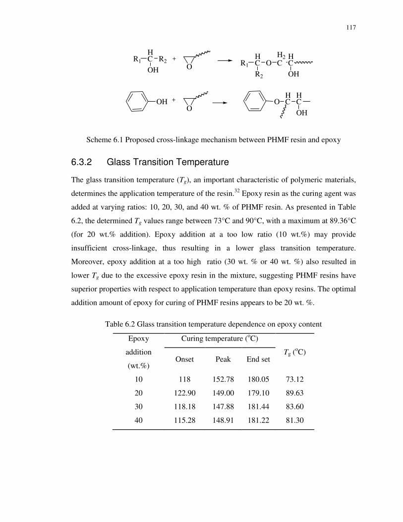
117
R1
HC R2
OH O R1
HC
R2
OH2C
HC
OH
OHO
OHC
HC
OH
Scheme 6.1 Proposed cross-linkage mechanism between PHMF resin and epoxy
6.3.2 Glass Transition Temperature
The glass transition temperature (Tg), an important characteristic of polymeric materials,
determines the application temperature of the resin.32 Epoxy resin as the curing agent was
added at varying ratios: 10, 20, 30, and 40 wt. % of PHMF resin. As presented in Table
6.2, the determined Tg values range between 73°C and 90°C, with a maximum at 89.36°C
(for 20 wt.% addition). Epoxy addition at a too low ratio (10 wt.%) may provide
insufficient cross-linkage, thus resulting in a lower glass transition temperature.
Moreover, epoxy addition at a too high ratio (30 wt. % or 40 wt. %) also resulted in
lower Tg due to the excessive epoxy resin in the mixture, suggesting PHMF resins have
superior properties with respect to application temperature than epoxy resins. The optimal
addition amount of epoxy for curing of PHMF resins appears to be 20 wt. %.
Table 6.2 Glass transition temperature dependence on epoxy content
Epoxy
addition
(wt.%)
Curing temperature (oC)
Tg (oC)
Onset Peak End set
10 118 152.78 180.05 73.12
20 122.90 149.00 179.10 89.63
30 118.18 147.88 181.44 83.60
40 115.28 148.91 181.22 81.30

118
6.3.3 Model-free Curing Kinetics
Understanding of curing kinetics can provide important information for polymer product
manufacture and applications. Heat release profiles in curing of PHMF resin with 20
wt.% epoxy were obtained at four heating rates and are shown in Figure 6.2. The cure
features, such as initial onset curing temperature (Ti), the peak temperature (Tp), end set
temperature (Te), and enthalpy (∆H) were obtained and displayed in Table 6.3. The cross-
linking reactions present an exothermic deflection from 101oC to 170oC. Similar behavior
was observed in PF novolac and the epoxy system by Lee et al. and Choi et al. at 100-
160oC but with a peak curing temperature Tp at around 120oC.33,34 Curing of the PHMF
resin requires relatively higher temperatures likely due to its limited reactivity to epoxy
and more steric hindrance than PF novolac. Figure 6.2 and Table 6.3 illustrate how Tp
shifts to a higher temperature region along with an increased heating rate, while the
enthalpy remains identical during the reactions.
50 100 150 200 250
Exo
ther
mic
Temperature (oC)
5
10
15
20
Figure 6.2 DSC spectra of the PHMF resin cured with 20 wt.% epoxy at various heating
rates

119
Table 6.3 Parameters for curing of PHMF resins with 20 wt.% epoxy at various heating
rates
β (oC/min) Tp (
oC) Ti ( oC) Te (
oC) ∆H∞ (J/g)
5 144.23 101.04 150.93 86.94
10 153.49 102.75 160.75 97.67
15 157.76 105.15 166.03 90.66
20 161.65 108.16 170.15 87.72
In this chapter, Kissinger and FWO plots were applied to obtain the activation energy
(Ea) and pre-exponential factor (A). The overall activation energies obtained from Eqs
(6.1) and (6.2) provide support for other literature results; for example, around
114kJ/mol. For comparison, the PHMF resin was also cured with the conventional agent
HMTA (as shown in Figure 6.3), and the kinetic parameters were calculated and are
shown in Table 6.4.
50 100 150 200 250Temperature (oC)
d
c
b
a
Exo
ther
mic
Figure 6.3 DSC spectra of the PHMF resin cured with 20 wt.% HMTA at various heating
rates: 5 (a), 10 (b), 15 (c), and 20 (d) oC/min

120
Table 6.4 Kinetics parameters for curing of PHMF resins with 20 wt.% epoxy or HMTA
Peak Temperature (°C) /Heating Rate (°C/min)
Kissinger Flynn-Wall-Ozawa
Sample
Ea (kJ/mol)
A Ea
(kJ/mol) 5 10 15 20
144.23 153.49 157.76 161.65 113.65 6.55E+10 114.80 PHMF+Epoxy
131.59 139.12 143.90 148.17 112.69 1.49E+11 113.69 PHMF+HMTA
6.3.4 Curing Kinetics in Iso-conversional Methods
100 110 120 130 140 150 160 170 180
0
20
40
60
80
100 dcb
Con
vers
ion
(%)
Temperature (oC)
a
Figure 6.4 Fractional conversion as a function of temperatures while curing PHMF and
20 wt.% Epoxy at various hearing rates of 5 (a), 10 (b), 15 (c), and 20 (d) oC/min
The heat flow under the exothermic plots is integrated against the temperature and then
processed to estimate fractional conversion (α) as well as the rate of reaction (dα/dt).35,36
As illustrated in Figure 6.4, a series of S-shaped curves were generated, representing the
degree of reaction α, which increases slowly at the beginning, faster in the middle stage,
and then levels off before completion. The fact that α levels off in the late curing stage
suggests that the curing reaction transitions from thermodynamic control to diffusion

121
control because of the reduced mobility of the reactive groups and increased cross-
linkages density.37,38 From the figure, it can be observed that, while increasing the heating
rate, the reaction conversion shifts to a higher temperature because a higher heating rate
does not allow enough time for the reactive groups to react. Thus a same degree of
reaction requires a higher temperature.
Table 6.5 Kinetic parameters obtained by iso-conversional methods for curing of PHMF
resins with 20 wt.% epoxy
α
Kissinger FWO
Ea
(kJ/mol) R2 A Ea (kJ/mol) R2 A
0.05 111.74 0.954 5.52E+11 112.51 0.959 1.70E+7
0.10 103.11 0.966 2.25E+10 104.39 0.970 4.47E+6
0.15 105.82 0.979 3.84E+10 107.02 0.981 5.73E+6
0.20 106.57 0.984 3.84E+10 107.78 0.986 5.75 E+6
0.25 107.45 0.985 4.19E+10 108.65 0.987 5.98 E+6
0.30 107.79 0.995 3.92E+10 109.01 0.995 5.82 E+6
0.35 108.98 0.995 4.87E+10 110.16 0.996 6.39 E+6
0.40 111.37 0.996 8.71E+10 112.46 0.997 8.17 E+6
0.45 110.14 0.995 5.37E+10 111.30 0.996 6.68 E+6
0.50 109.83 0.997 4.35E+10 111.04 0.998 6.12 E+6
0.55 110.24 0.997 4.42E+10 111.45 0.997 6.17 E+6
0.60 110.64 0.997 4.49E+10 111.85 0.997 6.22 E+6
0.65 111.05 0.997 4.56E+10 112.26 0.997 6.26 E+6
0.70 111.46 0.997 4.62E+10 112.66 0.997 6.31 E+6
0.75 112.72 0.997 6.04E+10 113.89 0.997 7.07 E+6
0.80 113.32 0.998 6.45E+10 114.48 0.999 7.28 E+6
0.85 110.11 0.995 2.26E+10 111.45 0.995 4.69 E+6
0.90 109.11 0.995 1.47E+10 110.53 0.995 3.92 E+6
0.95 107.82 0.989 8.57E+09 109.35 0.991 3.13 E+6
1 105.94 0.979 2.72E+09 107.69 0.982 1.95 E+6
Average 109.26 110.50
Furthermore, the model-free iso-conversional method was used to analyze the process.
The Ea, A, and correlation coefficient R2 values varied as reaction proceeded, and were
determined by both Kissinger and FWO methods (Table 6.5). Except that the correlation
coefficients (R2) at a conversion of 0.05 and 0.10 are below 0.98, the rest are all greater

122
than 0.98. As illustrated in Figure 6.5, Ea decreases at the beginning and then increases
gradually by roughly 1.3 kJ/mol for every 0.05 incremental growth in conversion,
remains stable after α = 0.4 and finally drops steadily to 105 kJ/mol. These results
indicate that the activation energy for the rate-determining step varies with degrees of the
curing process. The average values are a little lower but close to those shown in Table
6.4.
0 20 40 60 80 1000
20
40
60
80
100
120
140
Ea (
kJ/m
ol)
Conversion (%)
Kissinger FWO
Figure 6.5 Variation of Ea versus conversion for curing of PHMF resins with 20 wt.%
epoxy - comparison between Kissinger and FWO methods
6.3.5 Kinetics Modeling
The reaction kinetic parameters were determined by fitting the dynamic DSC conversion
data to the autocatalytic equation (i.e. Eq. 6.6) by using the least square regression
method, as shown in Figure 6.6. The obtained kinetic parameters are compiled in Table
6.6. As shown from the figure, there is congruence between the experimental data and
predicted data obtained from the autocatalytic model for all heating rates. From Table
6.6, for the curing reaction at all heating rates, E1 and E2 fall in a relatively narrow range
of 63-75 kJ/mol and 78-82 kJ/mol, respectively, and the overall order (n + m) of the
reaction is in the range of 1.0-1.3. These values are similar as those reported in
literature.39,40

123
Figure 6.6 Comparison of curing reaction rate for curing of PHMF resins with 20 wt.%
epoxy obtained by experiments (dots) and the model fitting (line) at various heating rates
of 5(a), 10(b), 15(c) and 20(d) oC/min
Table 6.6 Kinetic parameters derived from the autocatalytic model for curing of PHMF
resins with 20 wt.% epoxy
β k1 E1 (kJ/mol) n k2 E2 (kJ/mol) m
5 4.47E+04 62.92 0.39 1.92E+08 82.09 0.69
10 4.50E+04 75.00 0.31 1.77E+08 81.18 0.67
15 4.50E+04 60.90 0.51 1.29E+08 79.25 0.72
20 4.53E+04 64.46 0.49 1.24E+08 78.42 0.84
Ave 4.50E+04 65.82 0.43 1.55E+08 80.24 0.73
6.3.6 Thermal and Mechanical Behavior of the Cured PHMF Resin
The thermal stability of the 20 wt.% epoxy cured PHMF resin was determined by
thermogravimetric analysis (TGA) under nitrogen atmosphere, and the TGA curve is
illustrated in Figure 6.7. The TGA curve reveals the weight loss of substances in relation
to the temperature along with thermal degradation, while the first derivative of the TG

124
curve (DTG) shows the corresponding rate of weight loss, which is also shown in Figure
6.7. At temperatures up to 259oC, the hardened product is thermally stable. The peak of
the DTG curve (DTGmax) corresponds to the temperature where the fastest thermal
decomposition occurs, so it can be used to characterize thermal stability of the resin.
From Figure 6.7, the DTGmax occurred at 415 oC for the cured resin, and the fixed carbon
residue was 42.45% at 800oC, suggesting that the epoxy-harden PHMF resins can be
suitable for application in a wide temperature range.
0 100 200 300 400 500 600 700 8000
20
40
60
80
100
Temperature (oC)
Wei
ght (
%)
0.00
0.05
0.10
0.15
0.20
0.25
0.30
0.35
b
DT
G (
%/o C
)
a
Figure 6.7 TGA (a) and DTG (b) curves of the PHMF resin cured with 20 wt.% epoxy
Table 6.7 Thermal stability and mechanical property of the epoxy-cured PHMF resin
TGA DMA
T5 Tmax T50 Wt. % at
800oC. Tg (
oC)
259 415 523 42.45 173.8
The PHMF resins can be used as adhesives for the manufacture of fiber reinforced plastic
(FRP) bio-composites. In this study, the FRP bio-composite was produced using glass
fiber of an equal mass to that of the admixture of PHMF resin and epoxy hardener. DMA
measurement was performed on the profiles of the prepared FRP bio-composite. From

125
the DMA test, the storage modulus (E') and tanδ of the composite specimen were
calculated and shown in Figure 6.8. The storage modulus, proportional to the energy
stored during a loading cycle, represents the stiffness of the material. The Tg of the cured
samples was determined by the peak temperature of tanδ, which is defined by the ratio of
storage modulus to loss modulus. The measured Tg value for the bio-composite
determined by DMA was around 173.8°C, suggesting great enhancement through the
glass fiber addition compared with 89.63°C of the neat epoxy-cured PHMF resin
determined by DSC (Table 6.2). This implies that glass fiber imposes rigid bond and
steric restriction on the segment mobility in the cured resin.
50 100 150 200 2500
200
400
600
800
Temperature (oC)
E'(M
Pa)
0.00
0.04
0.08
0.12
0.16
0.20
tanδ
Figure 6.8 DMA profiles of the fiber reinforced plastic bio-composite using PHMF resin
cured with epoxy
In comparison, composites containing buriti fibers and cardanol-formaldehyde thermoset
composites only have Tg at about 80°C41 while oil palm/glass hybrid fiber reinforced PF
composites have Tg up to 140°C.42 The Tg of the bio-composite obtained in this study is
thus higher than other renewable composites, and it is comparable to Tg (from 175-
215°C) for epoxy cured PF novolac resins according to a report by Ogata et al.43
Nevertheless, more work is needed to investigate the mechanical properties of the epoxy-
cured PHMF resins as formaldehyde-free polymer matrix.
126
6.4 Conclusions
In this chapter, PHMF resin, as a formaldehyde-free bio-based phenolic resin, was cured
with bisphenol A type epoxy to avoid the emission of formaldehyde, a known human
carcinogen. The curing mechanism was investigated by DSC and FTIR measurements.
Epoxy resin as an effective cross-linker cured PHMF without generation of any by-
product. Curing of the PHMF resin and epoxy started at 105°C, and the PHMF resin with
addition of 20 wt.% of epoxy has a Tg of 89°C. The curing activation energy was
measured to be 110-113 kJ/mol, calculated from both model-free and iso-conversional
methods. Furthermore, the autocatalytic kinetic model was simulated and matched well
with experimental data. Thermo-gravimetric measurement demonstrated that the epoxy-
cured PHMF resin is thermally stable at temperatures up to 259oC. Its peak
decomposition temperature of the cured resin was also measured to be as high as 415oC
and the fixed carbon residue was 42.45% at 800oC. The formaldehyde-free PHMF resin
hardened with epoxy was also used to produce novel fiber reinforced plastic composite
materials having a high glass transition temperature of 173°C, suggesting the potential of
the epoxy cured PHMF resin for applications as formaldehyde-free matrix for bio-
composites.

127
References
1. Ragauskas AJ, Williams CK, Davison BH, Britovsek G, Cairney J, Eckert CA, Frederick WJ, Hallett JP, Leak DJ, Liotta CL. The path forward for biofuels and biomaterials. Science. 2006;311:484-489.
2. Netravali AN, Chabba S. Composites get greener. Mater Today. 2003;6:22-29.
3. US E. Extremely Hazardous Substances: Superfund Chemical Profiles. . Norwich, NY: William Andrew Publishing, 1988.
4. Hahnenstein I, Hasse H, Kreiter CG, Maurer G. 1H- and 13C-NMR Spectroscopic Study of Chemical Equilibria in Solutions of Formaldehyde in Water, Deuterium Oxide, and Methanol. Ind Eng Chem Res. 1994;33:1022-1029.
5. Kowatsch S. Formaldehyde. In: Pilato L . Phenolic Resins: A Century of Progress. Berlin: Springer, 2010:25-40.
6. Zakzeski J, Bruijnincx PCA, Jongerius AL, Weckhuysen BM. The catalytic valorization of lignin for the production of renewable chemicals. Chem Rev. 2010;110:3552-3599.
7. Yuan Z, Zhang Y, Xu C. Synthesis and Thermomechanical Property Study of Novolac Phenol-Hydroxymethyl Furfural (PHMF) Resin. RSC Adv. 2014;4:31829-31835.
8. Huber GW, Iborra S, Corma A. Synthesis of transportation fuels from biomass: chemistry, catalysts, and engineering. Chem Rev. 2006;106:4044-4098.
9. Klemm D, Heublein B, Fink HP, Bohn A. Cellulose: fascinating biopolymer and sustainable raw material. Angew Chem Int Ed. 2005;44:3358-3393.
10. Davda RR, Dumesic JA. Renewable hydrogen by aqueous-phase reforming of glucose. Chem Commun. 2004;1:36-37.
11. Davda RR, Shabaker JW, Huber GW, Cortright RD, Dumesic JA. A review of catalytic issues and process conditions for renewable hydrogen and alkanes by aqueous-phase reforming of oxygenated hydrocarbons over supported metal catalysts. Appl Catal ,
B. 2005;56:171-186.
12. Nielsen AT, Moore DW, Ogan MD, Atkins RL. Structure and chemistry of the aldehyde ammonias. 3. Formaldehyde-ammonia reaction. 1, 3, 5-Hexahydrotriazine. J
Org Chem. 1979;44:1678-1684.
13. Richmond HH, Myers GS, Wright GF. The reaction between formaldehyde and ammonia. J Am Chem Soc. 1948;70:3659-3664.

128
14. Jacobs DE, Kelly T, Sobolewski J. Linking public health, housing, and indoor environmental policy: successes and challenges at local and federal agencies in the United States. Environ Health Perspect. 2007;115:976-982.
15. Hsieh T, Su A. Cure kinetics of an epoxy‐novolac molding compound. J Appl Polym
Sci. 1990;41:1271-1280.
16. Mak HD, Rogers MG. Determination of chain branching in epoxy resins by nuclear magnetic resonance spectrometry. Anal Chem. 1972;44:837-839.
17. Batzer H, Zahir SA. Studies in the molecular weight distribution of epoxide resins. II. Chain branching in epoxide resins. J Appl Polym Sci. 1975;19:601-607.
18. Han S, Yoon HG, Suh KS, Kim WG, Moon TJ. Cure kinetics of biphenyl epoxy‐phenol novolac resin system using triphenylphosphine as catalyst. J Polym Sci A
Polym Chem. 1999;37:713-720.
19. Levchik SV, Weil ED. Thermal decomposition, combustion and flame‐retardancy of epoxy resins—a review of the recent literature. Polym Int. 2004;53:1901-1929.
20. Gagnebien D, Madec P, Marechal E. Synthesis of poly (sulphone-b-siloxane) s—I. Model study of the epoxy-phenol reaction in the melt. Eur Polym J. 1985;21:273-287.
21. Alvey FB. Selectivity of the epoxide phenol reaction. J Appl Polym Sci. 1969;13:1473-1486.
22. Burchard W, Bantle S, Zahir SA. Branching in high molecular weight polyhydroxyethers based on bisphenol A. Macromol Chem Phys. 1981;182:145-163.
23. Liu D, Shi Z, Matsunaga M, Yin J. DSC investigation of the hindered effect on curing behavior for epoxy–phenol/MMT nanocomposites based on the acidic octadecylamine modifier. Polymer. 2006;47:2918-2927.
24. Brunelle DJ, Evans TL. Contemporary Topics in Polymer Science. In: Salamone JC, Riffle JS. New York: Plenum Press, 1992:108.
25. Park SJ, Seo MK, Lee JR. Isothermal cure kinetics of epoxy/phenol‐novolac resin blend system initiated by cationic latent thermal catalyst. J Polym Sci , Part A: Polym
Chem. 2000;38:2945-2956.
26. Kissinger HE. Reaction kinetics in differential thermal analysis. Anal Chem. 1957;29:1702-1706.
27. Ozawa T. A new method of analyzing thermogravimetric data. Bull Chem Soc Jpn. 1965;38:1881-1886.
28. Flynn JH, Wall LA. A quick, direct method for the determination of activation energy from thermogravimetric data. J Polym Sci , Part B: Polym Phys. 1966;4:323-328.

129
29. Vyazovkin S, Sbirrazzuoli N. Isoconversional kinetic analysis of thermally stimulated processes in polymers. Macromol Rapid Commun. 2006;27:1515-1532.
30. Li T, Qin H, Liu Y, Zhong X, Yu Y, Serra A. Hyperbranched polyester as additives in filled and unfilled epoxy-novolac systems. Polymer. 2012;53:5864-5872.
31. El-Thaher N, Mekonnen T, Mussone P, Bressler D, Choi P. Nonisothermal DSC study of epoxy resins cured with hydrolyzed specified risk material. Ind Eng Chem Res. 2013;52:8189-8199.
32. Cai SX, Lin CH. Flame‐retardant epoxy resins with high glass‐transition temperatures from a novel trifunctional curing agent: Dopotriol. J Polym Sci , Part A: Polym Chem. 2005;43:2862-2873.
33. Lee YK, Kim DJ, Kim HJ, Hwang TS, Rafailovich M, Sokolov J. Activation energy and curing behavior of resol‐and novolac‐type phenolic resins by differential scanning calorimetry and thermogravimetric analysis. J Appl Polym Sci. 2003;89:2589-2596.
34. Choi WS, Shanmugharaj A, Ryu SH. Study on the effect of phenol anchored multiwall carbon nanotube on the curing kinetics of epoxy/Novolac resins. Thermochim
Acta. 2010;506:77-81.
35. Málek J. Kinetic analysis of crystallization processes in amorphous materials. Thermochim Acta. 2000;355:239-253.
36. Park BD, Riedl B, Hsu EW, Shields J. Differential scanning calorimetry of phenol–formaldehyde resins cure-accelerated by carbonates. Polymer. 1999;40:1689-1699.
37. Rivero G, Pettarin V, Vázquez A, Manfredi LB. Curing kinetics of a furan resin and its nanocomposites. Thermochim Acta. 2011;516:79-87.
38. Wan J, Wang S, Li C, Zhou D, Chen J, Liu Z, Yu L, Fan H, Li BG. Effect of molecular weight and molecular weight distribution on cure reaction of novolac with hexamethylenetetramine and properties of related composites. Thermochim Acta. 2011;530:32-41.
39. Kim WG, Lee JY. Contributions of the network structure to the cure kinetics of epoxy resin systems according to the change of hardeners. Polymer. 2002;43:5713-5722.
40. Ren S, Lan Y, Zhen Y, Ling Y, Lu M. Curing reaction characteristics and phase behaviors of biphenol type epoxy resins with phenol novolac resins. Thermochim Acta. 2006;440:60-67.
41. Santos R, Souza AA, Paoli MD, Souza CM. Cardanol-formaldehyde thermoset composites reinforced with buriti fibers: Preparation and characterization. Composites
Part A-Appl S. 2010;41:1123-1129.

130
42. Sreekala MS, Thomas S, Groeninckx G. Dynamic mechanical properties of oil palm fiber/phenol formaldehyde and oil palm fiber/glass hybrid phenol formaldehyde composites. Polym Compos. 2005;26:388-400.
43. Ogata M, Kinjo N, Kawata T. Effects of crosslinking on physical properties of
phenol–formaldehyde novolac cured epoxy resins. J Appl Polym Sci. 1993;48:583-601.

131
Chapter 7
7 Thermal, Physical and Mechanical Properties of HMTA-Cured Phenol-hydroxymethylfurfural (PHMF) Resin-based Glass Fiber Reinforced Composites - Effects of Amount of the Curing Agents
7.1 Introduction
The ever-growing concerns about the environment and sustainability have spurred the
development of sustainable and environmentally acceptable bioproducts in place of
petroleum-based products.1,2 Polymeric materials or plastics derived from abundantly
available and renewable sources are considered as the most promising materials because
of their potentially low costs and environmentally friendly nature.
HO
OH
O
OH
O
CHO
OH
OH
O
O
OH
OH
Figure 7.1 Structural representation of PHMF resin
As an example, glucose - the main building block of carbohydrates that makes up to 75%
of 170 billion metric tons biomass produced yearly by photosynthesis - can be converted
into hydroxymethylfurfural (HMF).3,4 HMF is a versatile platform chemical for a wide
variety of chemicals and polymer products. For example, it is considered as a substitute
for formaldehyde, a well known carcinogen widely used in producing phenol-
formaldehyde (PF) resins and urea-formaldehyde (UF) resins, etc.5. Novolac type phenol-
HMF (PHMF) resins (Figure 7.1) has been successfully synthesized by the author

132
through a one pot-process by reacting phenol and HMF in-situ derived from glucose, as
described in details in the previous chapters of this thesis. PHMF is a new class of
formaldehyde-free phenolic resins showing promise for replacing conventional
petroleum-based PF resins used as adhesives or polymer matrix in various high-
performance applications such as engineering wood products and fiber reinforced
composites.6
Fiber reinforced composite (FRC) of PF resin (novolac) are of particular interest. Owing
to its high strength, high stiffness and good corrosion resistance, FRC has gained
popularity in windmill blades, boat, aerospace, automotive, civil infrastructure, sports as
well as recreational sectors. Bio-composites produced with cost competitive green
components are more promising. Considerable growth has been seen in the use of bio-
composites, such as glass fibers reinforced composites with bio-based polymer matrix
materials, in the automotive and decking markets over the past few decades.7,8
The most commonly used curing agent for PF novolac is hexamethylenetetramine
(HMTA). Curing conditions, reaction mechanism and kinetic parameters between PF
novolac and HMTA or paraformaldehyde have attracted lots of research interests. For
instance, fast quantitative 13C NMR spectroscopy was applied to characterize the degree
of polymerization, number average molecular weight, and the number of un-reacted
ortho- and para phenol ring.9 The curing behaviour of novolac resin and
paraformaldehyde was discussed by using solid-state 13C NMR.10,11 This technique
showed that spin-lattice relaxation time T1H is sensitive, and the formaldehyde/phenol
ratio and the degree of the curing conversion can be quantitatively determined. However,
it was found that paraformaldehyde curing was unable to completely cure the novolac.
Zhang et al. also investigated the chemistry of novolac resin and HMTA upon curing
using 13C and 15N NMR techniques.12-14 Special attention was given to benzylamines and
benzoxazine that were formed as the reaction intermediates during the curing process.
Methylene linkages are formed to link novolac molecules with para-para linkages at
lower temperatures, while they are thermally less stable compared to ortho-linked
intermediates.

133
Curing parameter and conditions are critical to properties of phenolic materials. One of
the most common analyses was performed by differential scanning calorimetry (DSC).
The activation energy of approximately 144 kJ/mol and reaction constant have been
reported previously.15 Their curing reaction, recorded by rheometrics mechanical
spectroscopy, was described by a self-acceleration effect and a third order
phenomenological equation.16 Wan et al. further evaluated effects of the molecular
weight and molecular weight distribution on cure kinetics and thermal, rheological and
mechanical properties of novolac harden by HMTA.17 They reported that the novolac
resin with a lower molecular weight exhibited higher reaction heat and reactivity, faster
decomposition rate upon heating, lower char residue at 850 °C and higher flexural
strength of the composite materials.
In continuation of our earlier work, the main objective of the present work is to develop
the HMTA-cured PHMF based glass fibers reinforced composites and to maintain its
physical, thermal and mechanical properties through optimizing the addition amount of
the curing agent (the cross-linker). In order to find out the optimum concentration of the
cross-linker, samples were prepared using different concentrations of HMTA (10 wt%,
15 wt% and 20 wt%) and were further subjected to various characterizations. Tensile and
flexural strength was evaluated for the potential applications of these green composites as
structural materials in building, cars, interior decorations, furniture and packaging.
7.2 Materials and Methods
7.2.1 Materials
Reagent grade phenol (99.0%), CrCl2 (95.0%), CrCl3⋅6H2O (98.0%), D-glucose (99.5%),
tetraethyl ammonium chloride hydrate (TEAC, 99.0%) and hexamethylenetetramine
(HMTA) were purchased from Sigma-Aldrich. Tetrahydrofuran (THF, HPLC grade) was
obtained from Caledon Laboratories. All reagents were used as is without further
purification. BGF fiberglass cloth was purchased from Freeman, Ohio.

134
7.2.2 Synthesis of PHMF and PF Novolac Resins
The synthesis of phenol-HMF (PHMF) novolac resin was performed in a 100 mL ACE
round-bottom pressure flask with PTFE front-seal plug. Typically, 7.05 g phenol (0.075
mol), 27.0 g (0.15 mol) glucose, 0.0837 g CrCl2 (0.02 M), 0.0907 g CrCl3⋅6H2O (0.01
M), 0.3739 g (0.06 M) TEAC, and 6 g deionized water (10 wt.%) were added to the
reactor. The reactor was placed into an oil bath preheated to 120 oC and stirred with a
magnetic stirrer for 8 hours. The product was purified (to remove unreacted glucose and
phenol) by first removing water under vacuum using a rotary evaporator, dissolving the
remaining material in acetone, then removing the solid residue (mainly unreacted
glucose) by filtration. The acetone was removed by rotary evaporation under vaccum and
yielded PHMF in the form of a semi-solid material. As a reference, a conventional PF
novolac resin was prepared with a phenol-to-formaldehyde molar ratio of 1:0.85, using
HCl (0.5 wt.% of phenol) as catalyst.
7.2.3 Development of Composites
Mixtures of the HMTA and PHMF novolac matrix were prepared by dissolving the
ingredients in a 90% v/v mixture of acetone and water at 50 °C. Three different
formulations were produced with PHMF resin (PH) and HMTA (H) ratios of 100:10
(PHH10), 100:15 (PHH15), and 100:20 (PHH20). The resin mixture was applied to the
glass fiber at a 1:1 ratio by weight and was kept at room temperature for 24 h to allow the
solvent to evaporate. The dried resin was cured by hot pressing in a Carver hydraulic hot
press at 120 °C for 30 min, increasing to 150 °C for an additional 30 min, and then to 180
°C for a further 60 min under gradually increasing load up to 35 MPa (5000 psi). Upon
annealing at 180 °C for 5 h, the fully cured composite plates were cut into samples as
required by the ASTM standards. Given the unavoidable loss of the resin during the hot-
pressing process, the fully cured composite contained approx. 40% of resin, as confirmed
by burning the composite in a muffle furnace. For comparison, a conventional PF cured
with HMTA and glass fiber reinforced PF composite were prepared as described above.
The weight ratio of the PF resin (PF) and HMTA (H) was 100:15 (PFH15).

135
7.2.4 Mechanical Properties Tests
The tensile properties were measured using an Admet 7000 Universal Testing Machine in
accordance with ASTM D 638. Dumbbell specimens with length of 180 mm and width of
grip section of 10 mm were used. Crosshead speed was 10 mm per min and total
extension range was 25 mm. Tensile stress was applied till the failure of the sample and
the maximum applied stress prior to failure was recorded as the tensile strength. Stress-
strain relationship was obtained and its slope determined Young's modulus. Five
duplicates were made for each test.
The flexural modulus and flexural strength of the composite specimens were determined
following ASTM D790-M93 using the same universal testing machine. The rectangular
specimens in the dimension of 127 mm × 13 mm × 3 mm were performed on a three-
point bending apparatus with a support span of 50 mm and loaded at the crosshead speed
of 1.2 mm/min to the center of each specimen until failure. The flexural modulus and
flexural fracture strength were noted as the maximum applied stress prior to failure and
flexural modulus was obtained as the slope of load-displacement curve.
7.2.5 Chemical Resistance Tests
Chemical resistance of the fully cured composites was evaluated by putting the samples
with known weights in 5 N HCl or 5 N NaOH.18 The samples were dried in an oven at
70 °C for 24 h before testing to remove adsorbed water. After soaking, the samples were
removed from the solutions washed and dried at 50 °C to a constant weight. Loss in
weight was recorded at regular time intervals. Percentage weight loss was calculated as
follows in Eq. (7.1):
%100% ×−
=i
fi
W
WWlossWeight (7.1)
Where Wi and Wf are the initial and final weights of the sample, respectively.

136
7.2.6 Water Resistance Tests
Water resistance studies were carried-out as per ASTM D 570-81.19 The samples were
first dried in an oven at 70 °C for 24 h and then immersed in a deionized water bath at
ambient temperature. After 24 h, the samples were removed and dried with cotton cloth
and weighed again. The percentage weight gain was calculated by Eq. (7.2) as follows:
%100% ×−
=i
if
W
WWgainWeight (7.2)
Where Wi and Wf are the initial and final weights of the sample, respectively.
7.2.7 Thermogravimetric Analysis, Differential Thermogravimetric Analysis (TGA/DTG) and Thermalgravimetric Analysis-Infrared Spectroscopy (TG-IR)
Thermogravimetric analysis (TGA) was performed using a Pyris Diamond, Perkin–Elmer
thermal analyzer under nitrogen and air at a gas flow rates of 20 mL/min and a
temperature ramp rate of 10 °C/min up to 800 °C. The temperature profile used to cure
the PHMF resin was the same as was used in the preparation of the glass fibre composites
(i.e. 120 °C/30min + 150 °C/30min + 180 °C/6h).
The volatile products evolving from the PHMF-HMTA curing process were monitored
with a Perkin-Elmer TGA-FTIR coupled system through Perkin-Elmer’s TL 8000
transfer line.
7.2.8 Dynamic Mechanical Analysis
A DMA (Q800, TA Instruments) in a dual cantilever apparatus was used to determine
storage modulus (E') and loss modulus (E") of the specimens. Rectangular bar specimens
(60 mm × 10 mm × 1 mm) were used. The tests were performed in a temperature sweep
mode with a fixed frequency of 1 Hz and strain amplitude of 5 µm. Each specimen was
tested using a heating rate of 5 °C/min in air from room temperature to about 350 °C.
137
7.2.9 Rheological Measurements
A Rheologic Dynamic Analyzer (Rheometrics Inc, NJ) in parallel plate geometry was
employed in a strain-controlled time sweep mode to determine the elastic modulus (G′)
and related stress–strain properties of the pure PHMF resin without curing agent and
admixtures of the PHMF resin with various amounts of HMTA. Sample discs with a
diameter of 25 mm and thickness of 2 mm were used. The samples were heated for 1 min
at 120°C and then the measurement was carried out at constant temperature in the
frequency of 1 Hz and strain of 10%.
7.2.10 Scanning Electron Microscope (SEM) Measurements
Morphological images of HMTA-cured glass fiber reinforced PHMF composites before
and after damage were imaged on a Leo 1540XB scanning electron microscope (Zeiss,
Thornwood, NY, USA). The specimens were coated with osmium before examination.
7.3 Results and Discussion
7.3.1 TG-IR Monitoring of the PHMF-HMTA Curing Process
As a PF novolac resin cures, the ortho- and para- positions on the phenol rings can form
new methylene bridges by reacting with free formaldehyde20 which may be generated by
decomposition of HMTA at elevated temperatures. However, Pichelin et al. stated that
HMTA tends not to decompose into free formaldehyde but rather into intermediates such
as imino-methylene.21 Hatfield et al. proposed that the intermediates have structures of
benzoxazine and tribenzylamine as major components by merging HMTA into phenolic
resins.22 There are thus controversial standpoints on the emission of formaldehyde upon
curing. Using the TGA-FTIR coupled system, the composition of the volatile products
emitted during thermal curing process could be identified.
Figures 7.2a and 7.2b represent the stacked FT-IR spectra of the volatile products
evolved during the curing of the PHH15 and PFH15 resins, respectively, at a heating rate
of 10 °C/min in N2 atmosphere. As seen in Figure 7.2a, IR absorption peaks in the range
of 3200-2900 cm-1 and 1300 – 900 cm-1 indicative of formaldehyde were not observed up
to 350 ˚C, indicating that that no detectable formaldehyde was released from PHMF-
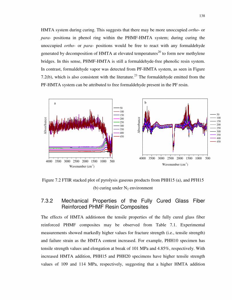
138
HMTA system during curing. This suggests that there may be more unoccupied ortho- or
para- positiona in phenol ring within the PHMF-HMTA system; during curing the
unoccupied ortho- or para- positions would be free to react with any formaldehyde
generated by decomposition of HMTA at elevated temperatures20 to form new methylene
bridges. In this sense, PHMF-HMTA is still a formaldehyde-free phenolic resin system.
In contrast, formaldehyde vapor was detected from PF-HMTA system, as seen in Figure
7.2(b), which is also consistent with the literature.23 The formaldehyde emitted from the
PF-HMTA system can be attributed to free formaldehyde present in the PF resin.
4000 3500 3000 2500 2000 1500 1000 500
Abs
orba
nce
Wavenumber (cm-1)
50 100 150 200 250 300 350 400 450
a
4000 3500 3000 2500 2000 1500 1000 500
50 100 150 200 250 300 350 400 450
Abs
orba
nce
Wavenumber (cm-1)
b
Figure 7.2 FTIR stacked plot of pyrolysis gaseous products from PHH15 (a), and PFH15
(b) curing under N2 environment
7.3.2 Mechanical Properties of the Fully Cured Glass Fiber Reinforced PHMF Resin Composites
The effects of HMTA additionon the tensile properties of the fully cured glass fiber
reinforced PHMF composites may be observed from Table 7.1. Experimental
measurements showed markedly higher values for fracture strength (i.e., tensile strength)
and failure strain as the HMTA content increased. For example, PHH10 specimen has
tensile strength values and elongation at break of 101 MPa and 4.85%, respectively. With
increased HMTA addition, PHH15 and PHH20 specimens have higher tensile strength
values of 109 and 114 MPa, respectively, suggesting that a higher HMTA addition

141
creates more cross-linkage between the resin molecules. Compared with PHH10, PHH15
and PHH20 specimens also have a higher failure strain, being 5.55 and 6.9%,
respectively. However, Young’s modulus was found to decrease monotonically from 21
to 16 GPa wwith increased HMTA addition], implying that increasing the amount of
curing agent decreases the stiffness of the composite materials. On the other hand, the PF
based composite cured with 15 wt.% HMTA (PFH15) exhibits much higher Young's
modulus value of 27 GPa, tensile strength of 225 MPa, and failure strain of ~8.18%,
indicating the conventional PF novolac resin as the polymer matrix for fiber reinforced
composites has better mechanical properties likely due to better reactivity and cross-
linkage of the PF-based composites.
Table 7.1 Tensile properties of the fully cured glass fiber reinforced PHMF and PF resin
composites
Elongation at
break (%)
Tensile
strength (MPa)
Young’s
modulus (GPa)
Extension
(mm)
PHH 10 4.9±0.3 101.5±4 20.9±1 2.7±0.1
PHH15 5.6±0.2 109.3±4 19.7±0.5 2.8±0.1
PHH20 6.9±0.1 114.3±2 16.5±0.1 3.5±0.1
PFH15 8.2±0.3 225.7±1 27.6±1 4.1±0.2
Although the tensile fracture strengths of PHMF-based composites are only half those of
conventional PF-based composites, the strength values are still better than some PF
composites or other type of resin-based composites. For example, glass/polyester
composite presented the maximum tensile fracture strength of 70 MPa and modulus of
700 MPa.24 Phenolic sheet moulding composite (SMC) has a tensile fracture strength of
96 MPa,25 and the tensile strength of the long glass fiber reinforced PF resin molding
compounds is 115 MPa, which is very comparable with the values obtained in this work
for the PHMF-based composites. George et al. reviewed natural fiber reinforced plastic
composites, particularly with respect to their optimal mechanical performance,26 where
these biocomposites have the maximum tensile strength of 35 MPa. Furthermore, the
strengths of some composites are listed under the ASTM D638 standard test, e.g., glass-

142
reinforced polyester and nylon, have 143 and 162 MPa tensile strength, respectively,
which are not much higher than those of the PHH15 or PHH20 FRC.
For 3-point bending tests of rectangular beam of the fully cured glass fiber reinforced
PHMF and PF resin composites, the flexural modulus was calculated by Eq. (7.3):
dwh
FLE
3
3
4= (7.3)
Flexural strength is defined by Eq. (7-4):
22
3
wh
FL=σ (7.4)
Where w(b) and h(d) are the width and height of the beam (mm), L is the length of the
support span (mm), d is the deflection due to the load F applied at the fracture point (N).
Table 7.2 Flexural properties of the fully cured glass fiber reinforced PHMF and PF resin
composites
Peak Strain
(%)
Maximum
load (N)
Flexural
modulus (Gpa)
Flexural strength
(MPa)
PHH 10 4.7±0.9 227.6±19 8.7±1 145.0±9
PHH15 6.3±1 228.7±8 6.5±0.6 138.0±8
PHH20 7.2±1 193.4±8 2.5±0.1 82.7±3
PFH15 2.6±0.2 364.8±8 11.9±1.1 233.1±13
It is evident from the 3-point bending tests results presented in Table 7.2 that increased
HMTA addition resulted in a higher failure strain but a reduction in the maximum load
from 227 N for PHH10 to 193 N for PHH20. Accordingly, increasing HMTA addition
drastically decreased the bending modulus or flexural modulus from 8.7 GPa for PHH10
to 2.5 GPa for PHH20. This result could be attributed to greater segmental mobility of the
cross-linked network at a higher HMTA addition resulting in a higher crosslink density.
In contrast, increased HMTA content resulted in a marked decline in flexural strength
from 145 MPa for PHH10 to 82 MPa for PHH20. This result was expected, as a more
highly crosslinked polymer (e.g. PHH20) would be expected to be more brittle. With a

143
higher level of curing agent, excessive cross-linkage might be generated in the form of
benzoxazine rings, leading to increased cross-linkage density and segment mobility for
the cured composites, thus affecting the flexural properties.27,28 As discussed in regards to
the tensile properties, the flexural properties of the PF-based composites are better than
those of the PHMF-based composites, with the exception of exhibiting lower strain. It
should be noted that however, the PHMF-based composites perform satisfactorily when
compared to the flexural properties of other common industrial composite materials. For
example, phenolic SMC was reported with 158 MPa flexural strength and 8.2 GPa
flexural modulus,25 in the similar range of the values for PHH10. Natural fiber and glass
fiber reinforced polymer composites that were studied for automotive applications have
the flexural properties similar (less than 15% difference) to those of the PHMF-based
composites.29 Glass fiber reinforced unsaturated polyesters presented 80 MPa flexural
strength and 6.0 GPa modulus which is less or similar those of the PHMF-based
composites.
7.3.3 Thermal Stability of the HMTA-Cured PHMF Resin
To examine the effect of HMTA addition on the thermal stability of cured PHMF novolac
resins, TGA data under nitrogen and air atmosphere were collected and analyzed. Figure
7.3 shows the weight loss and decomposition rate vs. temperature for PHMF resins cured
with various amounts of HMTA (10-20 wt.%). The characteristic results from the
TG/DTG profiles are summarized in Table 7.3.
In nitrogen atmosphere, the onset temperature T5 (5% weight loss) increased from 297 to
315 ˚C when HMTA addition was increased from 10 to 15 wt.% and did not change at 20
wt.% HMTA. The improved thermal stability of PHMF with increased HMTA addition
may be due to a greater crosslinking of the matrix, which may be inferred from the
TG/DTG profiles in Figure 7.3: the height of the decomposition rate (DTG) peak at about
320°C decreases with increased HMTA additionaddition. This peak may be due to the
degradation of ether groups presented in the HMTA-cured PHMF systems. All of the
resins exhibited a second decomposition peak at 455°C, which may correspond to
aliphatic group degradation. Char yields at 800°C obtained were as high as 59, 61 and
63% for PHH10, PHH15 and PHH 20, respectively, which also suggests a higher

144
crosslink density of the PHMF resin with increased HMTA addition, possibly due to
increased formation of benzoxazine rings in the PHMF resin upon heating.30
0 100 200 300 400 500 600 700 800
50
60
70
80
90
100
PHH10 PHH15 PHH20
Temperature (oC)
Wei
ght (
%)
0.0
0.2
0.4
0.6
Dec
ompo
siti
on R
ate
Figure 7.3 TG and DTG profiles of the cured PHMF resins with various amounts of
HMTA (10 – 20 wt%) in nitrogen atmosphere
Table 7.3 Summary of the TG/DTG results for the cured PHMF resins with various
amounts of HMTA (10 – 20 wt%) in nitrogen or air atmosphere
T5
a Thermal stability in N2 Char yield at 800 °C
(wt.%)
Sample N2 Air 1st DTG peak (°C)
2nd GTG peak (°C)
N2 Air
PHH10 297 313 315 452 59 0.77
PHH15 315 316 315 452 61 0.42
PHH20 315 310 327 455 63 0
aTemperature at 5% weight loss

145
Figure 7.4 features the weight loss and decomposition rate of PHH10, PHH15 and PHH
20 in air. The characteristic results from the TG/DTG profiles are also summarized in
Table 7.3. Generally the temperatures of the onset weight loss and maximum weight loss
rate shifted to higher temperatures, and the degree of shift increased with increased
HMTA addition. Similar observations have been reported in literature, where the high
heat resistance was ascribed to the curing of intermediates into benzoxazine type
structures.22 The 1st and the 2nd (dominant) decomposition temperatures of the HMTA-
cured PHMF resins in air are ~350 and ~650 °C, respectively, as compared to ~ 320 and
450 °C, respectively in N2. The most significant decomposition of the resin takes place at
~650°C, where aromatic structures are destroyed by combustion, and char is completely
oxidized by 800 °C.
0 100 200 300 400 500 600 700 8000
20
40
60
80
100
PHH10 PHH15 PHH20
Temperature (oC)
Wei
ght (
%)
0.0
0.2
0.4
0.6
Dec
ompo
siti
on R
ate
Figure 7.4 TG and DTG profiles of the cured PHMF resins with various amounts of
HMTA (10 – 20 wt%) in air atmosphere
7.3.4 Chemical and Water Resistance of Glass Fiber Reinforced PHMF Resin Composites
Generally, fully cured PHMF composites reinforced with glass fibers should exhibit
better chemical resistance towards acid and base at a higher HMTA addition, but best
performance was observed at HMTA addition of 15 wt.% addition (Figures 7.5a and b).
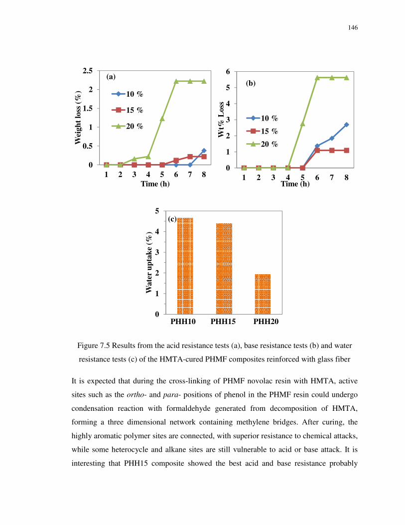
146
Figure 7.5 Results from the acid resistance tests (a), base resistance tests (b) and water
resistance tests (c) of the HMTA-cured PHMF composites reinforced with glass fiber
It is expected that during the cross-linking of PHMF novolac resin with HMTA, active
sites such as the ortho- and para- positions of phenol in the PHMF resin could undergo
condensation reaction with formaldehyde generated from decomposition of HMTA,
forming a three dimensional network containing methylene bridges. After curing, the
highly aromatic polymer sites are connected, with superior resistance to chemical attacks,
while some heterocycle and alkane sites are still vulnerable to acid or base attack. It is
interesting that PHH15 composite showed the best acid and base resistance probably
0
0.5
1
1.5
2
2.5
1 2 3 4 5 6 7 8
Wei
gh
t lo
ss (
%)
Time (h)
10 %
15 %
20 %
(a)
0
1
2
3
4
5
6
1 2 3 4 5 6 7 8
Wt%
Loss
Time (h)
10 %
15 %
20 %
(b)
0
1
2
3
4
5
Wate
r u
pta
ke
(%)
(c)
PHH10 PHH15 PHH20

147
because the amount of HMTA used was just sufficient enough to form a saturated three
dimensional cross-link in the novolac resin. Too high an addition of HMTA for the
PHH20 composite sample may have formed unstable end groups derived from HMTA,
decreasing the overall chemical resistance of the composites. More work is needed to
elucidate the mechanism for a solid explanation. As expected, the fully cured PHMF
composites showed improved water resistance at a higher HMTA addition (Figures 7.5c),
owing to the higher cross-linkage density expected with more HMTA addition, which
enhances the resistance of the material to water uptake.
7.3.5 Dynamic Mechanical Properties of the Fully Cured Glass Fiber Reinforced PHMF Resin Composites
50 100 150 200 250 300 3500
3000
6000
9000
12000
15000
Sto
rage
Mod
ulus
-E' (
MP
a)
Temperature (oC)
PHH10 PHH15 PHH20 PFH15
Figure 7.6 Storage moduli (E’) of the glass fiber reinforced PHMF composites cured with
different amounts of HMTA (10, 15 and 20 wt%) in comparison with the reference PF
composite cured with 15% HMTA
Figure 7.6 displays storage moduli (E’) of the glass fiber reinforced PHMF composites
cured with different amounts of HMTA (10, 15 and 20 wt.%) in comparison with the
reference PF composite cured with 15% HMTA. From the figure, the storage moduli of
the PHH10 and PHH15 are lower than that of PHH 20 below 230 °C, indicating that

148
increased addition of HMTA increases the rigidity of the cured composites, due to
increased cross-linkage within the polymer. However, at temperatures above the rubbery
plateau (> 230 °C), PHH15 showed the highest storage modulus. As is also clearly shown
from Figure 7.6, the storage modulus of the reference PF composite cured with 15%
HMTA is higher than all the PHMF-based composites, indicating superior
rigidity/stiffness.
Figure 7.7 illustrates tanδ vs. temperature profiles for the glass fiber reinforced PHMF
composites cured with different amounts of HMTA (10, 15 and 20 wt.%) in comparison
with the reference PF composite cured with 15% HMTA. The glass transition
temperature (Tg) can be read from the tanδ peak temperature in Figure 7.7, and the values
are presented in Table 7.4. As is clear from the tanδ profiles, that the Tg of the PHMF-
based composites increases with increased HMTA addition, which again may be
explained by a larger extent of cross-linking. It is worthy to note that the PHH20
composite has a Tg of 266°C, almost the same as that of the PF-based composite (267°C).
50 100 150 200 250 300 3500.00
0.02
0.04
0.06
0.08
0.10
0.12
0.14
0.16
tan δ
Temperature (oC)
PHH10 PHH15 PHH20 PFH15
Figure 7.7 tan δ vs. temperature profiles for the glass fiber reinforced PHMF composites
cured with different amounts of HMTA (10, 15 and 20 wt%) in comparison with the
reference PF composite cured with 15% HMTA
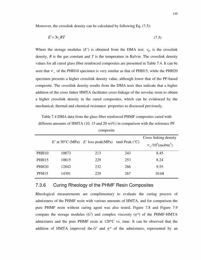
149
Moreover, the crosslink density can be calculated by following Eq. (7.5):
RTE eν3'= (7.5)
Where the storage modulus (E’) is obtained from the DMA test, νg, is the crosslink
density, R is the gas constant and T is the temperature in Kelvin. The crosslink density
values for all cured glass fiber reinforced composites are presented in Table 7.4. It can be
seen that eν of the PHH10 specimen is very similar as that of PHH15, while the PHH20
specimen presents a higher crosslink density value, although lower that of the PF-based
composite. The crosslink density results from the DMA tests thus indicate that a higher
addition of the cross linker HMTA facilitates cross-linkage of the novolac resin to obtain
a higher crosslink density in the cured composites, which can be evidenced by the
mechanical, thermal and chemical resistance properties as discussed previously.
Table 7.4 DMA data from the glass fiber reinforced PHMF composites cured with
different amounts of HMTA (10, 15 and 20 wt%) in comparison with the reference PF
composite
E’ at 50°C (MPa) E’ loss peak(MPa) tanδ Peak (°C)
Cross linking density
eν /105(mol•m3)
PHH10 10873 213 243 8.45
PHH15 10815 229 253 8.24
PHH20 12842 232 266 9.55
PFH15 14391 229 267 10.68
7.3.6 Curing Rheology of the PHMF Resin Composites
Rheological measurements are complimentary to evaluate the curing process of
admixtures of the PHMF resin with various amounts of HMTA, and for comparison the
pure PHMF resin without curing agent was also tested. Figure 7.8 and Figure 7.9
compare the storage modulus (G′) and complex viscosity (η*) of the PHMF-HMTA
admixtures and the pure PHMF resin at 120°C vs. time. It can be observed that the
addition of HMTA improved the G′ and η* of the admixtures, represented by an

150
exponential increase in G′ and η* values with time. It is also evident from the curve that
at the medium content (PHH15), the admixture was solidified fastest, compared to those
at 10 or 20% with respect to the solidification (curing) rate of the admixture. This result
is coincidently in agreement with the results as shown previously in Figures 7.5a and
7.5b, where the PHH15 composite showed the best acid and base resistance. These results
may imply that 15 wt. HMTA could be just sufficient enough to form a saturated three
dimensional cross-link in the novolac resin. A too high addition of HMTA for the PHH20
composite sample may form unstable end groups derived from HMTA, decreasing the
overall chemical resistance and slowing down the solidification process.
0 5 10 15
0
100000
200000
300000
400000
G' (
Pa)
Time (min)
PHH10 PHH15 PHH20 PHMF
Figure 7.8 Storage modulus (G’) vs. time profiles at 120°C of pure PHMF resin without
HMTA curing agent and admixture of PHMF with various amounts of HMTA

151
0 5 10 15
0
100000
200000
300000
400000
500000
600000
η∗(
Pa/
s)
Time (min)
10 15 20 PHMF
Figure 7.9 Complex viscosity (η*) vs. time profiles at 120°C of pure PHMF resin without
HMTA curing agent and admixture of PHMF with various amounts of HMTA
7.3.7 Morphology of the Fully Cured Glass Fiber Reinforced PHMF Resin Composites
Figure 7.10 SEM micrographs of undamaged (a) and damaged (b) glass fiber reinforced
PHMF resin cured with 15 wt.% HMTA (PHH15 composite)
Figure 10 shows the SEM micrographs of undamaged (a) and damaged (b) glass fiber
reinforced PHMF resin cured with 15 wt.% HMTA (the PHH15 cured composite). The
SEM micrograph of undamaged PHH15 (Figure 7.10a) displays the even widespread of
(b) (a)

152
fiber in the polymer matrix. The damaged (fracture) surface of the PHH15 specimen
(Figure 7.10b) shows cracks and disordered fibers pulled out of resin matrix, as well as
an uneven fracture surface of the composite suggesting significant matrix deformation.
7.4 Conclusions
Glass fiber reinforced PHMF resin cured with different additions of HMTA curing agent
(10-20 wt.%) were subjected to thermal, physical and mechanical analyses to investigate
the influence of amount of the curing (cross-linking) agent on the properties of the
resulting composite materials. Generally, increasing the addition of HMTA effectively
enhanced the composites’ tensile properties, thermal stability, storage modulus, crosslink
density and glass transition temperature, etc. However, the flexural properties,
rheological and chemical resistance tests suggest that 15 wt.% HMTA may be just
sufficient to form a saturated three dimensional cross-link in the novolac resin. Too high
an addition of HMTA to the PHMF resin may form unstable end groups derived from
HMTA, which decreases the overall chemical resistance of the resin and slows down the
solidification process. TGA-FTIR analysis did not detect the presence of formaldehyde
vapor in volatiles emitted during the curing of the PHH15 resin, whereas formaldehyde
was detected in during the HTMA curing of conventional PF resin. Thus, this study
demonstrates that PHMF resin may be used as a polymer matrix for fiber reinforced
composites and marketed as a formaldehyde-free producteven when HMTA is used as a
curing agent.

153
References
1. Daoutidis P, Marvin WA, Rangarajan S, Torres AI. Engineering biomass conversion processes: a systems perspective. AIChE J. 2013;59:3-18.
2. Klemm D, Heublein B, Fink HP, Bohn A. Cellulose: fascinating biopolymer and sustainable raw material. Angew Chem Int Ed. 2005;44:3358-3393.
3. Rosatella AA, Simeonov SP, Frade RFM, Afonso CAM. 5-Hydroxymethylfurfural (HMF) as a building block platform: Biological properties, synthesis and synthetic applications. Green Chem. 2011;13:754-793.
4. Röper H. Renewable raw materials in Europe—industrial utilisation of starch and sugar [1]. Starch - Stärke. 2002;54:89-99.
5. Kowatsch S. Formaldehyde. In: Pilato L . Phenolic Resins: A Century of Progress. Berlin: Springer, 2010:25-40.
6. Yuan Z, Zhang Y, Xu C. Synthesis and Thermomechanical Property Study of Novolac Phenol-Hydroxymethyl Furfural (PHMF) Resin. RSC Adv. 2014;4:31829-31835.
7. Shibata S, Cao Y, Fukumoto I. Flexural modulus of the unidirectional and random composites made from biodegradable resin and bamboo and kenaf fibres. Compos Part
A-Appl S. 2008;39:640-646.
8. Suharty NS, Wirjosentono B, Firdaus M, Handayani DS, Sholikhah J, Maharani YA. Synthesis of degradable bio-composites based on recycle polypropylene filled with bamboo powder using a reactive process. J Physi Sci. 2008;19:105-115.
9. Ottenbourgs BT, Adriaensens PJ, Reekmans BJ, Carleer RA, Vanderzande DJ, Gelan JM. Development and optimization of fast quantitative carbon-13 NMR characterization methods of novolac resins. Ind Eng Chem Res. 1995;34:1364-1370.
10. Ottenbourgs B, Adriaensens P, Carleer R, Vanderzande D, Gelan J. Quantitative carbon-13 solid-state nmr and FT-Raman spectroscopy in novolac resins. Polymer. 1998;39:5293-5300.
11. Bryson RL, Hatfield GR, Early TA, Palmer AR, Maciel GE. Carbon-13 NMR studies of solid phenolic resins using cross polarization and magic-angle spinning. Macromolecules. 1983;16:1669-1672.
12. Zhang X, Looney MG, Solomon DH, Whittaker AK. The chemistry of novolac resins: 3. 13C and 15N n.m.r. studies of curing with hexamethylenetetramine. Polymer. 1997;38:5835-5848.
13. Zhang X, Potter AC, Solomon DH. The chemistry of novolac resins: Part 7. Reactions of para-hydroxybenzylamineintermediates. Polymer. 1998;39:1957-1966.

154
14. Lim ASC, Solomon DH, Zhang X. Chemistry of novolac resins. X. Polymerization studies of HMTA and strategically synthesized model compounds. J Appl Polym Sci. 1999;37:1347-1355.
15. De Medeiros ES, Agnelli JAM, Joseph K, De Carvalho LH, Mattoso LHC. Curing behavior of a novolac‐type phenolic resin analyzed by differential scanning calorimetry. J
Appl Polym Sci. 2003;90:1678-1682.
16. Markovic S, Dunjic B, Zlatanic A, Djonlagic J. Dynamic mechanical analysis study of the curing of phenol‐formaldehyde novolac resins. J Appl Polym Sci. 2001;81:1902-1913.
17. Wan J, Wang S, Li C, Zhou D, Chen J, Liu Z, Yu L, Fan H, Li BG. Effect of molecular weight and molecular weight distribution on cure reaction of novolac with hexamethylenetetramine and properties of related composites. Thermochim Acta. 2011;530:32-41.
18. Kaith BS, Singha AS, Kumar S, Misra BN. FAS-H2O2 initiated graft copolymerization of methylmethacrylate onto flax and evaluation of some physical and chemical properties. J Polym Mater. 2005;22:425-431.
19. Liu W, Misra M, Askeland P, Drzal LT, Mohanty AK. ‘Green’composites from soy based plastic and pineapple leaf fiber: fabrication and properties evaluation. Polymer. 2005;46:2710-2721.
20. Lytle CA, Bertsch W, McKinley M. Determination of novolac resin thermal decomposition products by pyrolysis-gas chromatography-mass spectrometry. J Anal
Appl Pyrolysis. 1998;45:121-131.
21. Pichelin F, Kamoun C, Pizzi A. Hexamine hardener behaviour: effects on wood glueing, tannin and other wood adhesives. Eur J Wood Wood Prod. 1999;57:305-317.
22. Hatfield GR, Maciel GE. Solid-state NMR study of the hexamethylenetetramine curing of phenolic resins. Macromolecules. 1987;20:608-615.
23. Li W, Lu A, Guo S. Characterization of the microstructures of organic and carbon aerogels based upon mixed cresol–formaldehyde. J Appl Polym Sci. 2001;39:1989-1994.
24. Mouritz AP, Leong KH, Herszberg I. A review of the effect of stitching on the in-plane mechanical properties of fibre-reinforced polymer composites. Compos Part A-
Appl S. 1997;28:979-991.
25. Pilato L. Phenolic resins: A century of progress. Springer Verlag, 2010.
26. George J, Sreekala MS, Thomas S. A review on interface modification and characterization of natural fiber reinforced plastic composites. Polym Eng Sci. 2001;41:1471-1485.

155
27. Anseth KS, Kline LM, Walker TA, Anderson KJ, Bowman CN. Reaction kinetics and volume relaxation during polymerizations of multiethylene glycol dimethacrylates. Macromolecules. 1995;28:2491-2499.
28. Zhu J, Chandrashekhara K, Flanigan V, Kapila S. Curing and mechanical characterization of a soy‐based epoxy resin system. J Appl Polym Sci. 2004;91:3513-3518.
29. Holbery J, Houston D. Natural-fiber-reinforced polymer composites in automotive applications. JOM. 2006;58:80-86.
30. Espinosa MA, Cádiz V, Galia M. Synthesis and characterization of benzoxazine‐based phenolic resins: Crosslinking study. J Appl Polym Sci. 2003;90:470-481.

156
Chapter 8
8 Preparation and Characterization of Sawdust Bio-oil Phenol-HMF (SB-PHMF) Resins
8.1 Introduction
Phenol-formaldehyde resins (PF resins), currently produced by poly-condensation of
petroleum-based phenol and formaldehyde, play an indispensable role in the production
of many products (adhesives, fire retarding materials, etc.).1 However, according to some
studies in the United States of America, formaldehyde vapor of a concentration > 1 ppm
was regarded as a toxic chemical.2 The World Health Organization’s International
Agency for Research on Cancer classified formaldehyde to be carcinogenic to humans.
On the other hand, phenol and its vapors are corrosive to human eyes, skin, and the
respiratory tract.3 The substance may cause harmful effects on the central nervous system
and heart, resulting in dysrhythmia, seizures, and coma.4 As such, it is vital to seek for
less toxic green alternatives to formaldehyde and phenol for PF resins production. In
addition, the growing concerns toward energy security and the desire to reduce the
dependence on crude oil also contribute to the increasing interest in production of green
chemicals and fuels from renewable resources.5,6
Hydroxymethylfurfural (HMF) provides several advantages over formaldehyde as it is
environmentally friendly and more cost effective.7 Novel formaldehyde-free phenolic
resins, phenol-HMF (PHMF) resins have been developed by the author’s group by
reacting phenol and HMF in-situ derived from glucose, and the PHMF resins were
successfully utilized as a polymer matrix for the manufacture of glass fiber reinforced
composites,8,9 as described in the previous chapters. The motivation of this work is to
synthesize bio-phenol HMF resins by partially substituting phenol with bio-phenols
derived from renewable resources.
In fact, phenolic compounds are available by pyrolysis or solvolytic/hydrothermal
liquefaction of lignin or lignocellulosic materials.10,11 The solvolytic/hydrothermal
liquefaction of lignocellulosic materials in sub/near-critical water or hot-compressed

157
water-ethanol mixture demonstrated very effective for conversion of lignocellulosic
biomass into bio-crude oils or bio-phenol precursors for the synthesis of bio-based
phenolic resins.12-15 For example, Cheng et al. of the authors’ group realized high
conversion of biomass (95%) and bio-oil yield (65wt %) by liquefaction of woody
biomass in hot-compressed alcohol-water (50:50, w/w) at 300 ℃ for 15 min and a
solvent/biomass ratio of 10:1 (w/w).16 The bio-oil was used to replace phenol at high
level (up to 75wt %) to produce bio-based phenolic resole.17 Using the same conditions,
barks from white pine were converted to aromatic/phenolic-rich bio-crude oils, and the
obtained oils are rich in phenolic compounds, thus it is promising as a phenol-substitute
for the production of bio-phenolic resins.18
Inspired by research work reviewed above, producing bio-phenolic resins using liquefied
lignocellulosic biomass such as sawdust and bark is interesting and of significance with
respect to both environmental and economic benefits. However, thus far there is no study
aiming to produce bio-phenol HMF resins using sawdust bio-oil. The main goal of the
work was to synthesize sawdust bio-oil phenol-HMF (SB-PHMF) resins by reacting
phenol and bio-phenols –sawdust bio-oil (at various phenol substitution levels) and HMF
in-situ derived from glucose with catalysts in a one-pot process.
8.2 Material and Methods
8.2.1 Materials
Phenol and α-D-Glucose were obtained from Sigma-Aldrich, and used as received.
Formaldehyde (ca 37%) is from Anachemia, Montreal, QC, and used as received. White
Pine wood sawdust was collected from a local saw mill. The solvents used in this study
were distilled water, acetone (Fisher Scientific, Fair Lawn, NJ), and sodium hydroxide
solution (ca 50%, Ricca Chemical Co., Arlington, TX). Chromium (II) chloride (CrCl2),
chromium (III) chloride (CrCl3.6H2O), tetraethylammonium chloride (TEAC), and
hexamethylenetetramine (HMTA) were purchased from Sigma-Aldrich and used as
received.

158
8.2.2 Experimental Procedures
8.2.2.1 Preparation of Phenolic Bio-oil by Hydrothermal Liquefaction of Sawdust
As optimized by Cheng et al.,16 the liquefaction of pine sawdust was carried out in a 500
mL stainless steel autoclave reactor equipped with a mechanical stirrer and a water-
cooling coil. Specifically, 25 g oven-dried pine sawdust and 250 mL ethanol-water
(50:50, v/v) mixture were charged into the high pressure reactor, the residual air in the
reactor was thoroughly removed by vacuuming and the reactor was purged with N2 for
three purge-vacuum cycles. The reactor was then pressurized to 2 MPa. The completely
sealed reactor was then heated to 300 oC with stirring speed of 120-130 rpm and held for
15 min (pressure increases to around 11.5 MPa) before cooling down. After 15 minutes,
the reactor was quenched to room temperature. The gas inside the vessel was analyzed
using a Micro-GC equipped with Thermal Conductivity Detectors (TCD) to obtain the
composition (in moles) of gas species (H2, CO, CO2, CH4, and C2-C3). The liquid
products and solid residue in the reactor were collected, and the reactor was rinsed using
acetone. The slurry of liquid products and solid residue (SR) was then filtered. Filtrate
was rotary-evaporated under reduced pressure at 40-70°C to remove acetone, ethanol and
water respectively. At last, the obtained bio-oil was vacuum-dried at 60 oC overnight. The
residue after filtration was oven-dried at 105 oC to determine the sawdust conversion.
8.2.2.2 Synthesis of Sawdust Bio-oil PHMF Resins at Different Phenol Substitution Levels
Sawdust bio-oil phenol HMF (SB-PHMF) resins were synthesized by reacting sawdust
bio-oil, phenol, glucose and catalysts in a one-pot process described briefly below.
Sawdust bio-oil as a bio-phenol was applied to substitute phenol at different substitution
levels: i.e., 0 mol%, 25 mol%, 50 mol%, 75 mol% and 100 mol%, assuming the bio-oil
has an average molecular weight equal to lignin monomer (i.e., 180 g/mol). The
corresponding as synthesized bio-based PHMF resins were denoted as: 0%SB-PHMF,
25%SB-PHMF, 50%SB-PHMF, 75%SB-PHMF and 100%SB-PHMF. For instance, in
the experiment of synthesis of 25%SB-PHMF, raw materials loaded into the pressure
reactor included: 7.05 g phenol (0.075 mol) and 4.5 g sawdust bio-oil (0.025 mol), 18.00g

159
(0.1 mol) glucose, and 5 g water. Catalysts CrCl2 (0.02M), CrCl3.6H2O (0.01M), TEAC
(0.06M) in total about 0.3 g were added. It was however be noted that in the preparation
of 0%SB-PHMF or pure PHMF resin (the reference resin), 7.05 g phenol (0.075 mol) and
27.0 g (0.15 mol) glucose was used. Therefore, the glucose amount used in the 0%SB-
PHMF or pure PHMF resin synthesis is slightly different from those 25%-100%SB-
PHMF resins.
Specifically, all feedstock were added to a 100 mL glass pressure reactor capped with a
Teflon stopper. The reactor was put into a pre-heated 120oC oil bath and stirred with a
magnetic stirrer for 6 hours. By-products would be reduced by maintaining the
temperature at the desired level. After poly-condensation for 8 hours, the reaction was
stopped and cooled in a water bath until reaching room temperature. The final resin
products were obtained by rotary evaporation at reduced pressure to remove water,
followed by drying in a vacuum oven.
8.2.3 Products Characterization
Chemical components of bio-crude oil from hydrothermal liquefaction of sawdust were
qualitatively analyzed by a Gas Chromatography/Mass Spectrometry (GC/MS). Around
0.2 g diluted filtrate was collected into a GC/MS vial, further diluted with 1.0 g acetone.
The diluted sample was tested by GC/MS (Agilent 7890B GC, 5977AMSD) using a
silicon column with temperature programming from an initial temperature of 40 °C to 300
°C at the heating rate of 60 °C/min with 2 min initial and final time, respectively.
The properties of the feedstock sawdust bio-oil (SB) and the SB-PHMF resin products
were analyzed by Gel Permeation Chromatography (GPC), Fourier Transform Infrared
Spectroscopy (FTIR), High Performance Liquid Chromatography (HPLC) and
Differential Scanning Calorimeter (DSC). GPC was performed on a Waters Breeze
instrument (1525 binary pump with refractive index (RI) and UV detectors) for molecular
weights and distributions. FTIR was collected on with a Nicolet 6700 Fourier Transform
Infrared Spectroscopy for functional structure analysis. HPLC was used to determine the
remained free phenol content in the resins on a HPLC facility (1525 binary HPLC pump;
Agilent Hi-Plex H column with Guard at 60 oC) using 0.005M H2SO4 water solutions as

160
the eluent at a flow rate of 0.7 mL/min. The thermal curing properties of the resins were
evaluated without using any curing agent (i.e., self-curing like a resole) on a differential
scanning calorimetry (DSC, Mettler-Toledo, Schwerzenbach, Switzerland) under 50
ml/min N2 at four different heating rates (5, 10, 15 and 20 oC/min) between 50 oC and
250 oC in a sealed aluminum crucible. Thermogravimetric analysis (TGA) was carried
out using a Perkin-Elmer thermal analysis system with Pyris 1 TGA unit to obtain TG
and DTG curves. The SB-PHMF resins for the TGA tests were thermally self-cured
resins. The curing conditions were 120 oC for 30 min, 150 oC for 30 min, and 180 oC for
1 h. Some cured resins were fully cured at 180 oC for additional 5 h.
8.3 Result and Discussion
8.3.1 Characterization of Sawdust Bio-oil
The gross sawdust bio-oil (SB) yield from hydrothermal liquefaction of sawdust in
ethanol-water (50:50, v/v) mixture solvent at 300 oC for 15 min was in the range of 51-57
wt% based on the dry biomass feedstcok in multiple runs. Besides bio-oil as the main
product, other products include gas, solid residue (SR), and aqueous products (AP).
Yields of bio-oil, SR and Gas (gaseous products) were calculated by weight % of these
products in relation to dry weight of pine sawdust loaded into the reactor. For simplicity,
the yield of AP (including the pyrolytic water from the biomass) was calculated by
difference. The average yields of all products are presented in Figure 8.1. These yields
were similar to the reported results by Cheng et al. of the authors’ group in liquefaction
of woody biomass in hot-compressed alcohol-water (50:50, w/w) at the same condition
but smaller reactor 14-75 mL reactor.16
Chemical components of bio-crude oils from hydrothermal liquefaction of sawdust were
qualitatively analyzed by a Gas Chromatography/Mass Spectrometry (GC/MS). Table 8.1
presents GC-MS analysis results for the identified chemical compounds in the liquefied
pine sawdust bio-crude oil. It should however be noted that due to the limitation of GC
technology, only volatile portion of the oil was able to pass the GC column for detection
by MS, therefore the relative compositions reported in Table 8.1 are only for the volatile
compounds. From the GC-MS results, collectively the oil contains a greater percentage of

161
phenolic compounds; hence the oil was very suitable as a bio-alternative to phenol for
phenolic resin synthesis.
Figure 8.1 Yields of liquefaction products from pine sawdust (alcohol-water solvent
(50:50, w/w), 300°C, 15 min, solvent/biomass ratio of 10:1 (w/w))
Table 8.1 GC/MS identified main components in pine sawdust-derived bio-crude oils
Retention
Time (min) Name of compound
3.04 Ethyl 2-hydroxypropanoate
3.51 2-Furanmethanol
4.75 Propanoic acid
7.10 2-Furancarboxaldehyde
8.03 3-Methyl-1,2-cyclopentanedione
8.95 Phenol, 2-methoxy-
10.22 Phenol, 2-methoxy-4-(2-propenyl)-
11.25 Phenol, 2-methoxy-4-(2-propenyl)-
8.3.2 Production and Characterization of SB-PHMF Resins
HPLC tests were conducted on all SB-PHMF resins in order to determine the phenol
conversion, by measuring the phenol concentration in all resin samples. The results of
SB56%
SR5%
Gas8%
AP31%

162
phenol conversion along with the resin product yield (calculated by the weight of the as
synthesized resin in relation to the total weight of the SB, phenol and glucose) in the
experiments for producing the SB-PHMF resins at different phenol substitution ratios are
presented in Table 8.2. As clearly shown in the Table, the resin product yield ranged from
75-98 wt% in all experiments, and the phenol conversion was as high as 91 wt% in the
synthesis of pure PHMF resin (or 0%SB-PHMF). While the phenol substitution ratio was
increased (i.e., increasing sawdust bio-oil mol% in the SB-PHMF resins), the phenol
conversion decreased to 80% at 25% phenol substitution. Furthermore, the conversion
dropped drastically to 17-24 wt% at 50-75% phenol substitution, suggesting a detrimental
effect of SB on the phenol-HMF poly-condensation reaction, which might be due to the
dilution of phenol by SB and the shortage of phenol as a solvent for the PHMF product,
both retarding unfavorable effects for phenol conversion.
Table 8.2 Phenol conversion and resin product yield in the experiments for producing
SB-PHMF resins at different phenol substitution ratios
Sample Phenol conversion (wt%) Resin product yield (wt%)
0%SB-PHMF 91 75
25%SB-PHMF 80 81
50%SB-PHMF 17 92
75%SB-PHMF 24 90
100%SB-PHMF N/A 98
The molecular weight and distribution of all SB-PHMF resins and the sawdust bio-oil
(SB) determined by GPC-UV analysis are presented in Figure 8.2 and Table 8.3. From
the GPC analysis, the sawdust bio-oil has very low molecular weight Mn=231g/mol,
Mw=1682g/mol and a broad molecular weight distribution (PDI 7.29), implying that the
bio-oil contains a lot of oligomers derived from partial decomposition of the lignin and
cellulose components of the woody biomass. The 0%SB-PHMF or pure PHMF sample has
Mn=765g/mol, Mw=1850g/mol and a relatively narrow molecular weight distribution
(PDI 2.42), suggesting the successful resinification of phenol and glucose-derived HMF

163
in the reaction. When substituting 25-100% phenol with sawdust, the molecular weight
increase accompanied with a decrease in increasing the polydispersity, suggesting that the
bio-oil and phenol could resinify together HMF in the process resulting increased Mw and
Mn. In the experiment at a very high phenol substitution level, i.e., for the 100%SB-
PHMF test, less reaction would take place due to the lower reactivity of bio-oil compared
with phenol towards HMF, resulting in a relatively low Mw. The lower activity of bio-oil
compared with phenol towards HMF can be evidenced by the stronger absorbance of -
CHO (Carbonyl) group in the SB-PHMF resins compared with PHMF resin, evidenced
by the FTIR results (Figure 8.3).
5 10 15 20
0%SB-PHMF
25%SB-PHMF
50%SB-PHMF
75%SB-PHMF
100%SB-PHMF
UV
Abs
orba
nce
Time (Minute)
SB
Figure 8.2 Molecular weight distribution of all SB-PHMF resins and the sawdust bio-oil
Figure 8.3 shows the infrared spectrum of all the SB-PHMF resins. All SB-PHMF resins
displayed similar IR absorption profiles as the bio-oil as expected, even at the 0%SB-
PHMF (or pure PHMF) resin. This indicates that the SB-PHMF resins and PHMF resin
all have similar chemical structure. All resins have typical hydroxyl group absorption
between 3400 and 3387 cm-1, C-H stretching between 2980 and 2875 cm-1, and CHO
(aldehyde) stretching at 1700 cm-1. This is an evidence of incorporation of HMF to the
product as the FTIR spectrum of SB does not contain CHO absorbance.16 However, SB-
PHMF resins show more IR absorption at the -CHO (Carbonyl) group when compared

164
with PHMF resin, suggesting HMF remained after the reaction because of a lower
activity of bio-oil compared with phenol towards HMF. Sharp absorbance of carbon-
carbon stretching and aromatic vibration is observable at 1592 cm-1, implying abundance
of aromatics in the samples of SB and SB-PHMF. Aromatic ring vibration is shown at
1510 and 1450 cm-1, H-O bending at 1355 cm-1, methoxy group at 1260 cm-1, aromatic
ring stretching with oxygen around 1215 cm-1, guaiacyl band (C-O) at 1015 cm-1, and
aromatic ring out of plane bending with hydrogen at 748 cm-1.
Table 8.3 Molecular weights and polydispersity of all SB-PHMF resins and the sawdust
bio-oil
Sample Mn Mw PDI
0%SB-PHMF 765 1850 2.42
25%SB-PHMF 2529 4020 1.59
50%SB-PHMF 1670 3536 1.9
75%SB-PHMF 2026 4405 2.17
100%SB-PHMF 1532 2823 1.84
SB 231 1682 7.29
4000 3500 3000 2500 2000 1500 1000 500
methoxyCHO
25%SB-PHMF
50%SB-PHMF
75%SB-PHMF
100%SB-PHMF
Tra
nsm
itta
nce
(%)
Wavenumber (cm-1)
0%SB-PHMF
Figure 8.3 FTIR spectra of all SB-PHMF resins and the sawdust bio-oil

165
However, some difference can also be observed among above spectra. For example, the
IR absorption signal between 1668 and 1715 cm-1 (attributed to the carbonyl C=O
stretching from ketone, aldehyde, and ester and carboxylic acid groups) became stronger
for an SB-PHMF resins particularly with a higher bio-oil content. This could be
accounted for high contents of ketone, aldehyde, carboxylic acid, and ester groups in bio-
oil as was reported in a previous research.16
8.3.3 Self-Curing Behaviors and Kinetics
50 100 150 200 250
d
c
b
Temperature (°C)
Exo
ther
mic a
Figure 8.4 DSC curves for 100%SB-PHMF without any curing agent at varying heating
rate: 5 oC/min (a), 10 oC/min (b), 15 oC/min (c), and 20 oC/min (d)
An interesting phenomenon found during studying the cuing kinetics of the sawdust bio-
oil based PHMF resins is that our 25-100%SB-PHMF resins can achieve self-curing
without using any curing agent, which means with increasing temperature, the curing of
the resin can occur spontaneously. A possible reason to explain this phenomenon is that
there are plenty of extra functional groups (such as hydroxyl and aromatic, etc.) in bio-
oil, which could help the formation of cross-linking upon heating. The main reaction
might be the alkylation reactions between aromatic groups in SB-PHMF resins and the
hydroxymethylene groups in bio-oil. Figure 8.4 shows the DSC curves of the 100%SB-

166
PHMF without any curing agent at various heating rates: 5oC/min, 10oC/min, 15oC/min,
and 20oC/min.
DSC curves imply the curing reaction occurred at around 120 oC. From different heating
rates and peak temperatures obtained on the graph, the curing activation energy and the
order of the reaction can be calculated by the following classic methods:
Kissinger model19
:
)/(
)2/(p
RTa
EAe
pRT
aE
−=β (8.1)
Where β is heating rate, expressed by dtdT /=β . Pre-exponential factor A and apparent
activation energies Ea can be obtained by plotting )/ln( 2
pTβ− against pT/1 , where pT is
the peak temperature. By taking the logarithm, Eq. (8.2) can be derived from Eq. (8.1).
The advantage of the Kissinger model is that Ea is obtained without the knowledge of the
mechanism.
( )
+
−=−
R
E
TE
ART a
pa
p
1ln/ln 2β (8.2)
Flynn-Wall-Ozawa model (Eq. 8.3)20,21:
CRT
E
p
a +−=4567.0
log β (8.3)
In the pT/1~logβ plot, the slope isR
Ea4567.0− . Therefore, the calculation of Ea is
independent of the thermal curing mechanism.
Crane model (Eq. 8.4),22
nR
E
Td
d a
p
−=)/1(
)(lnβ (8.4)
If one plots pT/1~lnβ , the reaction order n could be calculated by the slope.

167
Table 8.4 Curing peak temperature and kinetic parameters for 100%SB-PHMF resin
Peak Temperature (°C)
/Heating Rate (°C/min)
Kissinger Flynn-Wall-
Ozawa Crane
Ea
(kJ/mol) A
Ea
(kJ/mol) n
5 10 15 20
113.89 119.97 121.14 124.86 159.4 2.15E+18 157.8 0.96
With the peak temperatures from the DSC curves (Figure 8.4), by employing the above
kinetic models the curing reaction kinetic parameters were estimated to be apparent
reaction order n = 0.96 (~ 1st order) and Ea = 159.4 kJ/mol (Kissinger) and Ea = 157.8
kJ/mol (Flynn-Wall-Ozawa), as summarized in Table 8.4. The curing activation energy
and apparent reaction order are in a good agreement with those reported in other bio-
phenolic resins.17
50 100 150 200
100%SB-PHMF
75%SB-PHMF
50%SB-PHMF
25%SB-PHMF
Temperature (°C)
Exo
ther
mic
0%SB-PHMF
Figure 8.5 DSC curves of all SB-PHMF resins without any curing agent at heating rate of
10oC/min
The DSC curves for curing of all SB-PHMF resins under a heating rate of 10oC/min are
illustrated in Figure 8.5. It is clearly shown that the pure PHMF (i.e., 0%SB-PHMF) resin

168
is not self-curable without exothermic curing peak (Figure 8.5), while all the bio-oil
based SB-PHMF resins are self-curable with curing peak temperatures in the range of
100-130°C. The self-curing of 100%SB-PHMF required a higher temperature (~ 130°C)
suggesting a lower reactivity of this resin probably due to a lower content of PHMF
function group in the 100%SB-PHMF sample.
60 80 100 120 140 160
0.0
0.2
0.4
0.6
0.8
1.0
Con
vers
ion
Temperature (oC)
25% SB-PHMF 50% SB-PHMF 75% SB-PHMF 100% SB-PHMF
Figure 8.6 Self-curing reaction extent changes for the SB-PHMF resins with respect to
temperature
By integrating exothermal peaks, the relative degree of curing as a function of
temperature can be generated and illustrated in Figure 8.6. From the figure, the reaction
extent α increases gradually at the beginning, then rapidly, and finally slowly before the
resins are completely cured. 100%SB-PHMF exhibits a different trend among other SB-
PHMF resins. The curing reaction started at a highest temperature than other SB-PHMF
resins (as also shown in Figure 8.5). This is nonetheless expected as the 100%SB-PHMF
resin contains the highest percentage of bio-oil, suggesting a lower reactivity of this resin
probably due to the less content of PHMF function group in the 100%SB-PHMF sample.
It was observed that the 25%SB-PHMF has the lowest gelation temperature and
100%SB-PHMF has the highest gelation temperature. However, 100%SB-PHMF resin
shows the shortest time spent on curing process (Figure 8.6).
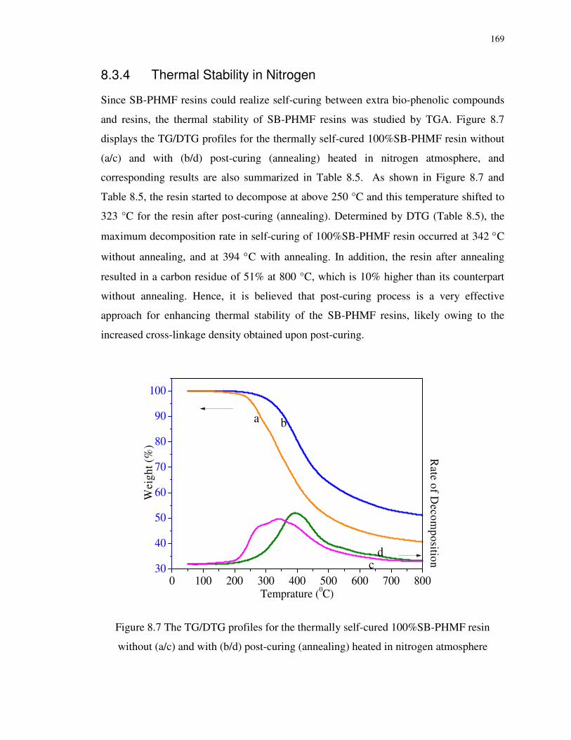
169
8.3.4 Thermal Stability in Nitrogen
Since SB-PHMF resins could realize self-curing between extra bio-phenolic compounds
and resins, the thermal stability of SB-PHMF resins was studied by TGA. Figure 8.7
displays the TG/DTG profiles for the thermally self-cured 100%SB-PHMF resin without
(a/c) and with (b/d) post-curing (annealing) heated in nitrogen atmosphere, and
corresponding results are also summarized in Table 8.5. As shown in Figure 8.7 and
Table 8.5, the resin started to decompose at above 250 °C and this temperature shifted to
323 °C for the resin after post-curing (annealing). Determined by DTG (Table 8.5), the
maximum decomposition rate in self-curing of 100%SB-PHMF resin occurred at 342 °C
without annealing, and at 394 °C with annealing. In addition, the resin after annealing
resulted in a carbon residue of 51% at 800 °C, which is 10% higher than its counterpart
without annealing. Hence, it is believed that post-curing process is a very effective
approach for enhancing thermal stability of the SB-PHMF resins, likely owing to the
increased cross-linkage density obtained upon post-curing.
0 100 200 300 400 500 600 700 80030
40
50
60
70
80
90
100
Rate of D
ecomposition
Wei
ght (
%)
Temprature (0C)
a b
cd
Figure 8.7 The TG/DTG profiles for the thermally self-cured 100%SB-PHMF resin
without (a/c) and with (b/d) post-curing (annealing) heated in nitrogen atmosphere

170
Table 8.5 Summary of the thermal stability studies of 100%SB-PHM resin in nitrogen
Sample
Maximum
decomposition
by DTG (°C)
Residue
left (%)
5%
Weight
lose (°C)
10%
Weight
lose (°C)
Residue at
800°C (%)
100%SB-
PHMF resin 342 76 257 281 41
100%SB-
PHMF resin
with post-
curing
394 82 323 358 51
8.4 Conclusions
Sawdust bio-oil phenol HMF (SB-PHMF) resins with phenol substitution ratio varying
from 0-100 mol% were synthesized by reacting sawdust bio-oil, phenol, glucose and
catalysts in a one-pot process at 120°C for 6h. The gross yields of different SB-PHMF
resins were from 75% to 98% by weight. Structure analysis by FTIR confirms the
formation of HMF according to absorption of CHO function group. However, with
increasing the phenol substitution level, the phenol conversion ratio and molecular
weights decreased, indicating a limited poly-condensation reaction in the presence of bio-
oil. In the SB-PHMF resin at a very high phenol substitution level, i.e., 100%SB-PHMF,
less reaction would take place due to the lower reactivity of bio-oil compared with
phenol towards HMF, resulting in a relatively low Mw. The lower reactivity of bio-oil can
be evidenced by the more remaining -CHO (carbonyl) group in the 100%SB-PHMF
resins compared with 0%SB-PHMF resin, evidenced by the FTIR results. Curing studies
on the SB-PHMF resins found that these resins are self-curable at > 120 oC without using
any curing agents. The self-curing reactions are 1st-order with activation energy around
160 kJ/mol. The cured SB-PHMF resins are thermally stable up to 250 °C, and even
higher than 300 oC after post-curing (annealing).

171
References
1. Pilato L. Phenolic resins: A century of progress. Springer Verlag, 2010.
2. US Environmental Protection Agency. Extremely Hazardous Substances: Superfund
Chemical Profiles. Norwich, NY: William Andrew Publishing, 1988.
3. O'Neil MJ, Budavari S. The Merck index: an encyclopedia of chemicals, drugs, and
biologicals. (13th edition). NJ: Merck: Whitehouse Station, 2001.
4. Warner MA, Harper JV. Cardiac dysrhythmias associated with chemical peeling with phenol. Anesthesiology. 1985;62:366-367.
5. Huber GW, Chheda JN, Barrett CJ, Dumesic JA. Production of liquid alkanes by aqueous-phase processing of biomass-derived carbohydrates. Science. 2005;308:1446-1450.
6. Huber GW, Iborra S, Corma A. Synthesis of transportation fuels from biomass: chemistry, catalysts, and engineering. Chem Rev. 2006;106:4044-4098.
7. Rosatella AA, Simeonov SP, Frade RFM, Afonso CAM. 5-Hydroxymethylfurfural (HMF) as a building block platform: Biological properties, synthesis and synthetic applications. Green Chem. 2011;13:754-793.
8. Yuan Z, Xu CC, Cheng S, Leitch M. Catalytic conversion of glucose to 5-hydroxymethyl furfural using inexpensive co-catalysts and solvents. Carbohydr Res. 2011;346:2019-2023.
9. Yuan Z, Zhang Y, Xu C. Synthesis and Thermomechanical Property Study of Novolac Phenol-Hydroxymethyl Furfural (PHMF) Resin. RSC Adv. 2014;4:31829-31835.
10. Demirbaş A. Mechanisms of liquefaction and pyrolysis reactions of biomass. Energy
Convers Manage. 2000;41:633-646.
11. Behrendt F, Neubauer Y, Oevermann M, Wilmes B, Zobel N. Direct liquefaction of biomass. Chem Eng Technol. 2008;31:667-677.
12. Yamazaki J, Minami E, Saka S. Liquefaction of beech wood in various supercritical alcohols. J Wood Sci. 2006;52:527-532.
13. Xu C, Lad N. Production of heavy oils with high caloric values by direct liquefaction of woody biomass in sub/near-critical water. Energy Fuels. 2007;22:635-642.
14. Yang Y, Gilbert A, Xu CC. Production of bio‐crude from forestry waste by hydro‐liquefaction in sub‐/super‐critical methanol. AICHE J. 2009;55:807-819.
15. Xu C, Etcheverry T. Hydro-liquefaction of woody biomass in sub-and super-critical ethanol with iron-based catalysts. Fuel. 2008;87:335-345.

172
16. Cheng S, D’cruz I, Wang M, Leitch M, Xu C. Highly Efficient Liquefaction of Woody Biomass in Hot-Compressed Alcohol− Water Co-solvents. Energy Fuels. 2010;24:4659-4667.
17. Cheng S, D'Cruz I, Yuan Z, Wang M, Anderson M, Leitch M, Xu CC. Use of biocrude derived from woody biomass to substitute phenol at a high‐substitution level for the production of biobased phenolic resol resins. J Appl Polym Sci. 2011;121:2743-2751.
18. Feng S, Yuan Z, Leitch M, Xu CC. Hydrothermal liquefaction of barks into bio-crude–Effects of species and ash content/composition. Fuel. 2014;116:214-220.
19. Kissinger HE. Reaction kinetics in differential thermal analysis. Anal Chem. 1957;29:1702-1706.
20. Ozawa T. A new method of analyzing thermogravimetric data. Bull Chem Soc Jpn. 1965;38:1881-1886.
21. Flynn JH, Wall LA. A quick, direct method for the determination of activation energy from thermogravimetric data. J Polym Sci, Part B: Polym Phys. 1966;4:323-328.
22. Crane LW, Dynes PJ, Kaelble DH. Analysis of curing kinetics in polymer composites. J Polym Sci Polym Phys Ed. 1973;11:533-540.

173
Chapter 9
9 Preparation and Characterization of Bio-Phenol-HMF (BPHMF) Resins using Phenolated De-polymerized Hydrolysis Lignin and Their Application in Fiber Reinforced Composites
9.1 Introduction
Although phenol-formaldehyde (PF) resins have a long history since they were first
invented in 1907, they still stand at an indispensable place among adhesives, binders and
fire retarding materials, etc.1,2 However, the growing concerns towards energy security,
the increasing price of phenol and the desire to reduce the dependence on crude oil give
impetus to increase the use of green alternatives in chemicals and materials production.3,4
Furthermore, both phenol and formaldehyde are toxic and even carcinogenic.
Formaldehyde vapor, if its concentration exceeds 1 ppm, is classified to be a carcinogen
by the World Health Organization’s International Agency. Phenol and its vapors are also
harmful to human eyes, skin, and the respiratory tract, as well as the central nervous
system and heart.5,6 Moreover, the price of phenol has been climbing noticeably in recent
years due to the rising price of crude oil.
Therefore, it is of significance to replace both formaldehyde and phenol with renewable
alternatives. Lignin is a by-product of the pulp industry and is a renewable polymer with
a polyphenolic structure similar to phenolic resin. Great efforts and progress have been
made in our group in valorization of lignin as a feedstock for the production of bio-based
chemicals and materials. The main objective of this work was to replace phenol with bio-
phenols derived from hydrolysis lignin via de-polymerization followed by phenolation to
generate a bio-phenol feedstock with decreased molecular weight and increased reactivity
for the production of formaldehyde -free bio-phenolic resin.
Hydroxymethylfurfural (HMF) has been effectively derived from glucose by catalytic
conversion.7 Replacing formaldehyde with glucose-derived HMF for phenolic resin is
advantageous with respect to both sustainability and cost.8 A new product, bio-phenol-

174
HMF (BPHMF) resins can be anticipated by replacing phenol partially with lignin and
formaldehyde (totally) with glucose, feedstock that originated not from petroleum
resources, but from renewable bio-resources.
In fact, there have been substantial research efforts made on the utilization of lignin as an
alternative of phenol in synthesizing lignin-modified phenol-formaldehyde (LPF) resins,
but incorporating lignin directly into the PF synthesis has been a challenge as crude lignin
has less reactive sites than phenol to react with aldehydes.9 Lignin modifications to obtain
more reactive functional groups have been used commonly to this end, which includes
phenolation,10 methylolation,11 demethylation12 and hydrothermal de-
polymerization/liquefaction13,14. The final resin behavior was found to be very dependent
on the chemical and physical properties of the lignin. Direct phenolation of lignin due to
its simplicity was widely applied for use in phenolic resins.10
The lignin extracted from the residues of enzymatic hydrolysis process is called
enzymatic hydrolysis lignin (EHL).15 Acid hydrolysis lignins, commercial by-products of
the acid saccharification process of wood, is part of lignocellulosic residues.16 Lignin,
cellulose and other carbohydrates are the main components of hydrolysis residues that
contain alkali-soluble kraft lignin and water-soluble lignosulphonates.
Inspired by previous research work reviewed above, it is thus interesting and of great
significance to de-polymerize lignin and phenolate the de-polymerized lignin to produce
a bio-phenolic feedstock with decreased molecular weight (hence reduced steric
hindrance) and increased reactivity for the production of bio-phenolic resins. To the best
of the authors’ knowledge, there is no publication regarding the synthesis of
formaldehyde-free bio-based phenolic resins using de-polymerized lignin and glucose-
derived HMF. The main objective of this research was to synthesize green adhesive,
formaldehyde-free bio-based phenolic resins using de-polymerized lignin and glucose-
derived HMF, and examine its curing behavior and thermomechanical performances to
demonstrate its potential in the production of fiber reinforced plastics.

175
9.2 Material and Methods
9.2.1 Materials
Phenol and α-D-Glucose were obtained from Sigma-Aldrich and used as received.
Hydrolysis lignin was supplied by FPInnovations, a byproduct from its proprietary
hardwood fractionation process for bioproducts (or called “TMP-bio process”).17 The HL
contains >50-60 wt% lignin balanced by the residual cellulose and carbohydrates. The
molecular weight was believed >20,000 g/mol, but not measurable due to its insolubility
in a solvent. The solvents used in this study were distilled water, acetone (Fisher
Scientific, Fair Lawn, NJ), and a sodium hydroxide solution (ca 50%, Ricca Chemical
Co., Arlington, TX), all used as received. The synthesis process for the BPHMF resins
involved catalysts such as Chromium (II) chloride (CrCl2), chromium (III) chloride
(CrCl3.6H2O) and tetraethylammonium chloride (TEAC) were obtained from Sigma-
Aldrich, and the details were described in previous chapters. Hexamethylenetetramine
(HMTA) was obtained from Sigma-Aldrich and was used as a curing agent for the
BPHMF resins.
9.2.2 De-polymerization of Hydrolysis Lignin and Phenolation of De-polymerized Hydrolysis Lignin
The de-polymerization hydrolysis lignin was carried out in a 500 mL stainless steel
autoclave reactor equipped with a mechanical stirrer and a water-cooling coil. Briefly, the
HL de-polymerization process was operated in a solvent at 150-300 oC for 30 min to 120
min under low operating pressure (<150 psi) at a substrate concentration of 5wt%-30
wt%. The process resulted in a moderately high yield of de-polymerized HL (DHL) (70
wt%) with a solid residue (SR) of ~ 10wt%. The process was found to be very cost-
effective and highly efficient for the depolymerization/liquefaction of HL of a very high
molecular weight (Mw >20,000 g/mol) into DHL with a much lower molecular weight
(1000-2000 g/mol). The detailed operating conditions are protected due to the patent
application, but it is not critical for this research as the present work intended only to
utilize the DHL for the synthesis of bio-phenolic resins.

176
To phenolate the DHL, an equal amount of DHL and phenol as well as 2% of sulfuric
acid and solvent acetone were charged into an autoclave reactor and heated to 120 oC for
3 h. The solvent was removed by rotary evaporation and vacuum drying.
9.2.3 Synthesis of BPHMF Resin
Phenolated DHLs were used as raw material to synthesize BPHMF resins. We focused
our analysis and discussion on a phenolated DHL with 50% phenol substitution level in
this work. In a typical synthesis run for BPHMF resin, 14.10 g phenolated DHL
(containing 50 wt% phenol and 50 wt% DHL), 13.5 g (0.075 mol) glucose, and 6 g water
and a total of 0.3 g catalysts (0.02M CrCl2, 0.01M CrCl3.6H2O, 0.06M TEAC) were
loaded into a 100 mL glass pressure reactor capped with a Teflon stopper. The reactor
was put into a preheated 120oC oil bath and stirred with a magnetic stirrer for 6 hours.
The products were dried by rotary evaporation and vacuum drying. GC-MS tests were
conducted on the resulting BPHMF resin in order to calculate the phenol conversion into
resin. The phenol conversion was determined to be approximately 60% and the
unconverted free phenol was recovered by steam distillation. Moreover, phenol
conversion was improved by adding glucose fraction in among raw materials. For
comparison purposes, a PHMF resin was also synthesized using the same procedure and
conditions as reported above, except that neat phenol was used instead of phenolated
DHL.
9.2.4 Feedstock and Product Characterizations
The chemical/thermal/mechanical properties of the feedstock and products produced in
this work were characterized using various techniques, including Gel Permeation
Chromatography (GPC), Fourier Transform Infrared Spectroscopy (FTIR), Gas
chromatography–mass spectrometry (GC-MS), Differential Scanning Calorimeter (DSC),
Thermogravimetric analysis (TGA) and Dynamic Mechanical Analysis (DMA).
The molecular weights distribution profiles of DHL before and after phenolation as well
as the BPHMF resin were measured by gel permeation chromatography (GPC, Waters
Styrylgel HR1) using THF as the eluent and linear polystyrene as standards for
calibration. The functional group of the BPHMF resin was analyzed using FTIR (Perkin-

177
Elmer Spectrum Two IR Spectrometers). As mentioned previously, the remaining free
phenol concentration in the resins was detected by GC-MS on an Agilent 7890B GC
coupled with a 5977A MSD using a 30 m × 0.5 mm × 0.25 µm DB-5 column with
temperature program as follows: a 1 min hold at an initial temperature of 50 °C followed
by a 30 °C min−1 ramp to a final temperature of 280 °C with 1 min hold. The thermal
curing properties of the resins were evaluated with a differential scanning calorimetry
(DSC, Mettler-Toledo, Schwerzenbach, Switzerland) under 50 ml/min N2 at a ramp rate
of 10 oC/min between 50 oC and 250 oC in a sealed aluminum crucible. The thermal
stability of the BPHMF resins was examined by thermogravimetric analysis (TGA) with
5-10 mg thermally pre-cured resins (120 oC for 30 min, 150 oC for 30 min, and 180 oC for
1 h) on a Perkin-Elmer thermal analysis system with Pyris 1 TGA unit. The samples were
measured in nitrogen at a flow rate of 20 ml/min; the ramp rate was 10 oC/min. The
dynamic mechanical properties (such as glass transition temperature, Tg) of the cured
BPHMF composites were characterized using dynamic mechanical analyzer (DMA
Q800, TA Instruments) at 5 oC/min. Composites were prepared by applying
homogeneous solution of BPHMF and HMTA onto glass fiber at 1/1 ratio (w/w) and
keeping at room temperature until solvent evaporated. The sample was cured by hot
pressing in a Carver hydraulic hot press using the same procedure as resin curing under
the load of 35 MPa (5000 psi). The pressed composites were also shaped into dumbbell-
shaped samples and their tensile strengths were measured in accordance to ASTM 638 on
an ADMET Expert 7600 universal test machine.
9.3 Result and Discussion
9.3.1 Characterizations of DHL, PDHL, and BPHMF Resins
The gross yield of synthesized BPHMF resins was 85% under the conditions as described
in the experimental section (14.10 g phenolated DHL (containing 50 wt% phenol and 50
wt% DHL), 13.5 g (0.075 mol) glucose, and 3 g water and a total of 0.3 g catalysts were
reacted at 120oC for 8 hours). The yield of BPHMF resins could be further increased by
increasing the glucose level in the reaction substrate.

178
The approximate molecular weight and distribution obtained from BPHMF resin and its
comparison with DHL and PDHL are presented in Figure 9.1 and Table 9.1.
Figure 9.1 Molecular weight distribution of the DHL, PHMF and BPHMF resin
Table 9.1 Average molecular weights and polydispersity of the DHL, PHMF and
BPHMF resin
Mn
(g/mol)
Mw
(g/mol) Polydispersity Index (PDI)
DHL N/A 1400-
1500 N/A
PDHL 870 2107 2.42
BPHMF 1082 9030 8.34
The GPC profiles of DHL and PDHL indicate that they have similar molecular weight
and distribution, which is consistent with the low phenol conversion (4%) in the
phenolation process. Even at such low phenol conversion, on average two third of DHL

179
molecules were phenolated, due to the large difference in the molecular weights of DHL
and neat phenol. The GPC profile of BPHMF exhibited a much broader weight
distribution and a larger value of polydispersity than DHL and PDHL. More interestingly,
most components of BPHMF present a lower retention time than PDHL, as indicated by
the peaks of GPC profiles (Figure 9.1). Upon polycondensation with glucose-derived
HMF in the resinification process, the molecular weight and PDI of the PDHL increased
four times, demonstrating that the resinification reactions proceeded well. Specifically,
the BPHMF resins have broad molecular weight distribution (PDI = 8.34), and large Mw
(9030 g/mol) and Mn (1082 g/mol).
Figure 9.2 FTIR spectra of the BPHMF resin, DHL and PDHL
Figure 9.2 shows that the infrared spectra of BPHMF resin. The BPHMF resin has similar
chemical structure to PF resin. There is typical hydroxyl group absorption between 3400
and 3387 cm-1 and C-H stretching between 2980 and 2875 cm-1. Sharp absorbance of
carbon-carbon stretching and aromatic vibrations at 1592 cm-1 represent abundance of
aromatics of phenol, lignin and HMF. Aromatic ring vibration is at 1510 and 1450 cm-1,
H-O bending at 1355 cm-1, methoxy group at 1260 cm-1, aromatic ring stretching with
oxygen around 1215 cm-1, guaiacyl band (C-O) at 1015 cm-1, and aromatic ring out of

180
plane bending with hydrogen at 748 cm-1. The carbonyl (CHO) stretching at 1663 cm-1 is
present due to the carboxylic acid among BPHMF because end aldehyde group remained.
Based on the structure analysis and related reference on PHMF resin,8 a reaction
mechanism can be proposed by Scheme 9.1.
OH
O
OH
OHOHO
OH
OHOH
CrClx/TEAC OCHO
HO
OH
CrClxOH
CrClx
OH
O
OOHC OH
CrClx BPHMF resin
OH
OH
HO
OH
O
OH
HO
OH
O
HO
OOHC
Scheme 9.1 Reaction mechanism of the synthesis of BPHMF resin from bio-phenols and
in-situ generated HMF
9.3.2 Curing Behaviors of BPHMF Resin
Since BPHMF resins contain very few reactive sites, additional curing agents such as
epoxy resin, lignin and HMTA are necessary to achieve cross-linking and curing of the
resin. In addition, as the temperature increases, self-curing might also occur between
PDHL and resin as there are extra functional groups in lignin (such as hydroxymethylene
groups and hydroxyl groups) that could contribute to the formation of cross-linking. A
possible reaction might be the alkylation reaction between aromatic groups in resin and
hydroxymethylene groups in lignin. Figure 9.3 presents the DSC measurement result of
BPHMF at a heating rate of 10oC/min in nitrogen in comparison with PHMF resin, both
using HMTA as the curing agent. DSC curves imply that the curing reaction for both
resins starts at 120oC, peaks around 150 oC and ends after 200 oC, which is a common
phenomenon for many bio-phenolic resins.13,14

181
50 100 150 200 250
b
E
xoth
erm
ic
Temperature [°C]
a
Figure 9.3 DSC profiles of BPHMF (a) and PHMF resins (b) cured with 15 wt% HMTA
BPHMF needs a longer time than PHMF for completion of the curing process. This
phenomenon may be explained by its low reactivity of the lignin-derived bio-phenols and
the self-curing mechanism as explained before between the resin and lignin functional
groups.
9.3.3 Thermal Stability
The synthesized BPHMF resin was also investigated using TGA-DTG for its thermal
stability. As displayed in Figure 9.4, the BPHMF resin started to decompose after 300 °C
in either air or nitrogen atmosphere and this temperature is close to PHMF resin (Table
9.2), suggesting that similar thermal stability of BPHMF resin with that of PHMF resin.
Table 9.2 shows the comparison between thermal stability of BPHMF and PHMF resin
upon being heated in nitrogen and air. The maximum decomposition temperature of
BPHMF is close to that of the PHMF by 60 °C, implying significant enhancement of
thermal resistance owing to the presence of the lignin-derived bio-phenols. Further, the
BPHMF resin resulted in a close carbon residue to PHMF resin, approximately 60 wt% at
800 °C in nitrogen and 10 wt% in air, almost 10% higher than that of the PHMF resin
(Table 9.2). This might be due to the slower breakdown of aromatic linkages in lignin

182
structures and its high aromatic fractions. Interestingly, the BPHMF resin behaved
durable thermal stability in air, as represented by the higher weight residue (70-80 %) at
500°C, above which the resin sharply decomposed in air.
100 200 300 400 500 600 700 800
0
20
40
60
80
100
BPHMF+HMTA, N2
BPHMF+HMTA, air
Temprature (0C)
Wei
ght (
%)
0.0
0.2
0.4
0.6
0.8
1.0
Dec
ompo
siti
on R
ate
Figure 9.4 Thermal stability and decomposition rate of cured BPHMF resin in nitrogen
(a) and air (b)
Table 9.2 Comparison of thermal stability of BPHMF and PHMF resin upon being heated
Sample Gas
Maximum decompositio
n by DTG (°C)
Residue left (%)
5% Weight lose (°C)
10% Weight lose (°C)
Residue at 800°C (%)
BPHMF N2
434 78 313 351 59
PHMF 372 88 315 358 61
BPHMF Air
680 31 318 366 3
PHMF 641 38 317 365 0.42
9.3.4 Dynamic Mechanical Analysis
Dynamic mechanical properties of the BPHMF-fiberglass composite were measured as a
function of temperature. Besides the information on the glass transition temperature (Tg)
value, three other important parameters can also be obtained for complete understanding

183
of the viscoelastic behavior of the composite, i.e., storage modulus (E′), loss modulus
(E″) and tangent delta (tan δ), which are intercorrelated through the following expression:
'
"tan
E
E=δ (9.1)
50 100 150 200 250 3002000
4000
6000
8000
10000
12000
14000
Temperature (0C)
a
0.02
0.04
0.06
0.08
0.10
0.12
tan
del
ta
Sto
rage
Mod
ulus
(M
Pa)
50 100 150 200 250 3002000
4000
6000
8000
10000
12000
Temperature (0C)
Sto
rage
Mod
ulus
(M
Pa)
0.040
0.045
0.050
0.055
0.060
0.065b
tan
del
ta
Figure 9.5 Dynamic mechanic analysis of BPHMF – fiberglass composite (a) in
comparison with PHMF– fiberglass composite (b)
Figure 9.5 shows the dynamic mechanic analysis of BPHMF–fiberglass composite in
comparison with PHMF–fiberglass composite. There is a generally decreasing trend in
the storage modulus as the temperature increases. However, the storage modulus is not
decreasing constantly over the entire temperature range, where a significant drop of its
value occurs at 190-300 °C, which corresponds to the glass transition temperature range
of both BPHMF- and PHMF- fiberglass composites. Below 190 °C, the temperature
region is characterized by a glassy behavior where the stiffness of the material is of its
highest value as compared with the rest of the temperature regions. As shown in the
figure, there is a slight decrease in the storage modulus along with increasing temperature
under 100 °C mainly due to the incomplete curing. The composite samples would
undergo a transition from a glassy (highly stiff) region to a soft rubbery plateau region
when the temperature increases beyond Tg.
Tan δ serves as a balance indicator between the elastic phase and viscous phase of a
polymeric material.18 The damping peak obtained by the loss tangent plot corresponds to
the glass transition temperature Tg. Comparing between the damping peaks of the

184
BPHMF – fiberglass composite (Figure 9.5a) with the PHMF– fiberglass composite
(Figure 9.5b), the incorporation of DHL into the polymer matrix (BPHMF) led to an
increase in its composite glass transition temperature Tg (272°C), when compared with
that of the PHMF polymer matrix (243°C).
9.3.5 Mechanical Properties of FRP using BPHMF resin cured with HMTA
Table 9.3 gives the comparison of the tensile strengths of woven fiberglass cloth-PHMF
resin composites cured with HMTA compared with that of the BPHMF FRC. The
BPHMF composites have tensile strength of around 89 MPa, with a 20% inferior to that
of PHMF composite. These are actually comparable to tensile strength of commercial
phenolic FRC.
Table 9.3 Tensile strengths of BPHMF and PHMF FRC cured with HMTA
Sample Tensile strength
BPHMF+HMTA 89 ± 1 MPa
PHMF+HMTA 109 ± 4 MPa
9.4 Conclusions
In this chapter, formaldehyde-free bio-phenol HMF resins (BPHMF) has been
synthesized by reacting phenolated de-polymerized hydrolysis lignin with HMF (5-
hydroxymethylfurfural) in-situ derived from glucose in the presence of catalysts. Gross
yield of BPHMF resin is 85 % by weight at the optimal conditions. Structure analysis by
FTIR confirms that the resinification process, leading to the increased molecular weights
(weight-average weight) of BPHMF resins at around 9030 g/mol. Comparing a Mw of
2107 g/mol for the PDHL and 2800 g/mol for PHMF resin, it can be concluded that
substantial poly-condensation PDHL with HMF during the synthesis went smoothly. The
BPHMF resin cured with HMTA was found to be thermally stable until 300 oC in either
nitrogen or air. Compared with PHMF resins, the BPHMF resin needs a higher
temperature for curing, but achieved higher storage modulus and Tg, thus it has
acceptable thermomechanical properties.

185
References
1. Pilato L. Phenolic resins: A century of progress. Springer Verlag, 2010.
2. Gardziella A, Pilato LA, Knop A. Phenolic resins: Chemistry, applications,
standardization, safety and ecology. (2nd edition). Heidelberg: Springer, 2000.
3. Huber GW, Chheda JN, Barrett CJ, Dumesic JA. Production of liquid alkanes by aqueous-phase processing of biomass-derived carbohydrates. Science. 2005;308:1446-1450.
4. Huber GW, Iborra S, Corma A. Synthesis of transportation fuels from biomass: chemistry, catalysts, and engineering. Chem Rev. 2006;106:4044-4098.
5. O'Neil MJ, Budavari S. The Merck index: an encyclopedia of chemicals, drugs, and
biologicals. (13th edition). NJ: Merck: Whitehouse Station, 2001.
6. Warner MA, Harper JV. Cardiac dysrhythmias associated with chemical peeling with phenol. Anesthesiology. 1985;62:366-367.
7. Rosatella AA, Simeonov SP, Frade RFM, Afonso CAM. 5-Hydroxymethylfurfural (HMF) as a building block platform: Biological properties, synthesis and synthetic applications. Green Chem. 2011;13:754-793.
8. Yuan Z, Zhang Y, Xu C. Synthesis and Thermomechanical Property Study of Novolac Phenol-Hydroxymethyl Furfural (PHMF) Resin. RSC Adv. 2014;4:31829-31835.
9. Wang M, Leitch M, Xu C. Synthesis of phenol–formaldehyde resol resins using organosolv pine lignins. Eur Polym J. 2009;45:3380-3388.
10. Alonso MV, Oliet M, Rodrıguez F, Garcıa J, Gilarranz M, Rodrıguez J. Modification of ammonium lignosulfonate by phenolation for use in phenolic resins. Bioresour
Technol. 2005;96:1013-1018.
11. Alonso MV, Oliet M, Pérez JM, Rodrıguez F, Echeverrıa J. Determination of curing kinetic parameters of lignin–phenol–formaldehyde resol resins by several dynamic differential scanning calorimetry methods. Thermochim Acta. 2004;419:161-167.
12. Ferhan M, Yan N, Sain M. A New Method for Demethylation of Lignin from Woody Biomass using Biophysical Methods. J Chem Eng Process Technol. 2013;4:160.
13. Cheng S, Wilks C, Yuan Z, Leitch M, Xu CC. Hydrothermal degradation of alkali lignin to bio-phenolic compounds in sub/supercritical ethanol and water–ethanol co-solvent. Polym Degrad Stab. 2012;97:839-848.
14. Cheng S, Yuan Z, Anderson M, Anderson M, Xu CC. Highly efficient de-polymerization of organosolv lignin using a catalytic hydrothermal process and

186
production of phenolic resins/adhesives with the depolymerized lignin as a substitute for phenol at a high substitution ratio. Ind Crop Prod. 2013;44:315-322.
15. Jin Y, Cheng X, Zheng Z. Preparation and characterization of phenol–formaldehyde adhesives modified with enzymatic hydrolysis lignin. Bioresour Technol. 2010;101:2046-2048.
16. Dizhbite T, Zakis G, Kizima A, Lazareva E, Rossinskaya G, Jurkjane V, Telysheva G, Viesturs U. Lignin—a useful bioresource for the production of sorption-active materials. Bioresour Technol. 1999;67:221-228.
17. Yuan Z, Browne TC, Zhang X. Biomass fractionation process for bioproducts. US
Patent. 2011;US20110143411 A1.
18. Hassan A, Rahman NA, Yahya R. Extrusion and injection-molding of glass fiber/MAPP/polypropylene: effect of coupling agent on DSC, DMA and mechanical properties. J Reinf Plast Compos. 2011;30:1223-1232.

187
Chapter 10
10 Conclusions and Future Work
10.1 Conclusions
The aim of this work was to develop formaldehyde-free phenolic resins using glucose to
substitute formaldehyde and utilize the resins as polymer matrixes for fiber reinforced
composites. Catalyzed by sulfuric acid, phenol-glucose resin was first obtained at low
yield and cured with bisphenol A type epoxy. Then glucose was catalytically converted to
HMF, an aromatic aldehyde, and reacted with phenol to form PHMF resin in a one pot
process. Epoxy resin proved to be an excellent curing agent for the novolac PHMF resins.
The curing kinetics as well as properties of cured resin were studied. Continuing the work
mentioned above, curing of the PHMF resin with green curing agents, i.e. organosolv
lignin and Kraft lignin was studied. As a comparison, conventional cross linker HMTA
was used for producing fiber reinforced composites with PHMF resins. Furthermore,
highly sustainable bio-phenolic resins were produced by partially replacing phenol with
sawdust bio-oil or phenolated depolymerized hydrolysis lignin to apply these bio-phenol
HMF resins in glass fiber reinforced composites.
The following detailed conclusions can be drawn from this work:
(1) The curing reaction between phenol-glucose (PG) resin and bisphenol A type
epoxy resin took place at around 155 oC. A curing mechanism was proposed,
involving the formation of secondary alcohols by connecting the epoxy ring and
the aromatic hydroxyl group from the PG resin. Average activation energy Ea for
the curing reaction was about 108 kJ/mol based on various methods. The Sestak-
Berggren autocatalytic model with the expression of nmf )1()( ααα −= was found
to fit best for the curing kinetics.
(2) The reactivity and conversion of glucose were enhanced by reacting phenol with
in-situ generated HMF in the presence of a Lewis acid catalyst in a one-pot
process, producing phenol-hydroxymethyl furfural (PHMF) resins. Here
carcinogenic formaldehyde is substituted with renewable, nontoxic, and

188
inexpensive glucose. Extended by the polycondensation between aldehyde and
hydroxyl groups of HMF and phenol, the resins have a similar structure to
novolac PF resin and were curable using HMTA. The PHMF resins may have
great potential to replace Novolac PF resin in many applications such as polymer
matrixes for composites materials.
(3) Curing of the PHMF started at 120 °C and peaked at around 150 °C by employing
organosolv lignin or Kraft lignin. The curing mechanism was elucidated. Glass
fiber reinforced composites were prepared using the PHMF resin polymer matrix
cured by lignin. Good thermo-mechanical properties, such as the thermal stability
and the glass transition temperature of up to ~270°C, was found to be similar to
those of the HMTA-cured PF resin.
(4) PHMF resin was cured using bisphenol A type epoxy as an alternative for HMTA.
Similar to the curing mechanism of PG resin, epoxy resin curing of PHMF did not
generate by-products. Curing of the PHMF resin using epoxy peaked at 150 °C,
and the activation energy was about 112 kJ/mol. Autocatalytic kinetic model was
used to simulate the experimental data. The cured resin was thermally stable up to
259oC and the glass fiber reinforced composite materials produced using epoxy
resin cured PHMF matrix had a glass transition temperature of 173°C.
(5) Glass fiber reinforced PHMF resin cured with different amounts of the curing
agent, HMTA, were subjected to thermal, physical and mechanical analyses to
investigate the influence of amount of the cross-linker on the properties of the
resulting composites materials. Generally, increasing the amount of HMTA
effectively enhanced the composites’ tensile properties, thermal stability, storage
modulus, crosslink density, glass transition temperature, etc. However, the
flexural properties, rheological and chemical resistance tests also suggested that
15 wt% HMTA could be sufficient enough to form a saturated three dimensional
cross-link in the novolac resin. TG-IR analysis demonstrated that the PHMF resin
is a useful formaldehyde-free phenolic resin as a polymer matrix for fiber
reinforced composites even using HMTA as a curing agent.
(6) Sawdust bio-oil phenol HMF (SB-PHMF) resins with phenol substitution ratio
varying from 0-100 mol% were synthesized by reacting sawdust bio-oil, phenol,

189
glucose and catalysts in a one-pot process at 120°C for 6h. The gross yields of
different SB-PHMF resins were from 75% to 98% by weight. Structure analysis
by FTIR confirms the formation of HMF according to absorption of CHO
functional group. However, with increasing the phenol substitution level, the
phenol conversion ratio and molecular weights decreased, indicating a limited
poly-condensation reaction in the presence of bio-oil. Curing studies on the SB-
PHMF resins found that these resins are self-curable at > 120 oC without using
any curing agents. The self-curing reactions are 1st-order with activation energy
around 160 kJ/mol. The cured SB-PHMF resins are thermally stable up to 250 °C,
and even higher than 300 oC after post-curing (annealing).
(7) Formaldehyde-free bio-phenol HMF resins (BPHMF) has been synthesized by
reacting phenolated de-polymerized hydrolysis lignin with HMF (5-
hydroxymethylfurfural) derived from glucose in-situ. Gross yield of BPHMF
resin is 85 % by weight at the optimal conditions. Structure analysis by FTIR
confirms that the resinification process lead to the increased molecular weights
(weight-average weight) of BPHMF resins at around 9030 g/mol, comparing to a
Mw of 2107 g/mol for the PDHL and 2800 g/mol for PHMF resin. The BPHMF
resin cured with HMTA was found to be thermally stable until 300 oC in either
nitrogen or air. Compared with PHMF resins, the BPHMF resin needs a higher
temperature for curing, but it has achieved higher storage modulus and Tg, thus it
has acceptable thermomechanical properties.
10.2 Future Work
(1) HMF plays an important role in carbohydrates biorefinery because it can be
obtained from fructose, glucose and cellulose and converted into a wide variety of
value-added chemicals and materials. Glucose has lower reactivity and more side-
products for HMF production, so more work is needed to develop more effective
catalysts and optimize the reaction conditions to enhance the HMF yield from
glucose.
(2) Lignin depolymerization with selective bond cleavage is a hot research topic for
converting it into valuable phenolic compounds to substitute phenol in the

190
synthesis of bio-phenolic resins. Currently most lignin de-polymerization
processes involve either higher pressure/temperature or hydrogen. More research
is needed to explore more efficient lignin depolymerization processes to obtain de-
polymerized lignin at lower molecular weights.
(3) Although PHMF resins exhibit acceptable physical, thermal, and mechanical
properties, more research work is needed to functionalize the resins to enhance its
reactivity and cross linkage density after curing.
(4) Technoeconomical analysis of whole process for the production of formaldehyde-
free PHMF or BPHMF resins should be carried out.

191
Appendix
Appendix 1: Permission to Reuse Copyrighted Materials
Permission of Figure 1.1 and Figure 2.3

192
Permission of Figure 2.2
THE AMERICAN ASSOCIATION FOR THE ADVANCEMENT OF SCIENCE LICENSE TERMS AND CONDITIONS
Dec 31, 2014
This is a License Agreement between Yongsheng Zhang ("You") and The American Association for the Advancement of Science ("The American Association for the Advancement of Science") provided by Copyright Clearance Center ("CCC"). The license consists of your order details, the terms and conditions provided by The American Association for the Advancement of Science, and the payment terms and conditions.
All payments must be made in full to CCC. For payment instructions, please see information listed at the bottom of this form.
License Number 3539510002532
License date Dec 31, 2014
Licensed content publisher The American Association for the Advancement of Science
Licensed content publication Science
Licensed content title The Path Forward for Biofuels and Biomaterials
Licensed content author Arthur J. Ragauskas, Charlotte K. Williams, Brian H. Davison,
George Britovsek, John Cairney, Charles A. Eckert, William J.
Frederick Jr., Jason P. Hallett, David J. Leak, Charles L. Liotta,
Jonathan R. Mielenz, Richard Murphy, Richard Templer, Timothy
Tschaplinski
Licensed content date Jan 27, 2006
Volume number 311
Issue number 5760
Type of Use Thesis / Dissertation
Requestor type Scientist/individual at a research institution
Format Electronic
Portion Text Excerpt
Number of pages requested 1
Order reference number None
Title of your thesis /
dissertation
PRODUCTION AND APPLICATIONS OF FORMALDEHYDE-FREE
PHENOLIC RESINS USING 5-HYDROXYMETHYLFURFURAL DERIVED
FROM GLUCOSE IN-SITU
Expected completion date Dec 2014
Estimated size(pages) 200

193
Total 0.00 CAD
Terms and Conditions
American Association for the Advancement of Science TERMS AND CONDITIONS
Regarding your request, we are pleased to grant you non-exclusive, non-transferable permission, to republish the AAAS material identified above in your work identified above, subject to the terms and conditions herein. We must be contacted for permission for any uses other than those specifically identified in your request above.
The following credit line must be printed along with the AAAS material: "From [Full Reference Citation]. Reprinted with permission from AAAS."
All required credit lines and notices must be visible any time a user accesses any part of the AAAS material and must appear on any printed copies and authorized user might make.
This permission does not apply to figures / photos / artwork or any other content or materials included in your work that are credited to non-AAAS sources. If the requested material is sourced to or references non-AAAS sources, you must obtain authorization from that source as well before using that material. You agree to hold harmless and indemnify AAAS against any claims arising from your use of any content in your work that is credited to non-AAAS sources.
If the AAAS material covered by this permission was published in Science during the years 1974 - 1994, you must also obtain permission from the author, who may grant or withhold permission, and who may or may not charge a fee if permission is granted. See original article for author's address. This condition does not apply to news articles.
The AAAS material may not be modified or altered except that figures and tables may be modified with permission from the author. Author permission for any such changes must be secured prior to your use.
Whenever possible, we ask that electronic uses of the AAAS material permitted herein include a hyperlink to the original work on AAAS's website (hyperlink may be embedded in the reference citation).
AAAS material reproduced in your work identified herein must not account for more than 30% of the total contents of that work.
AAAS must publish the full paper prior to use of any text.
AAAS material must not imply any endorsement by the American Association for the Advancement of Science.

194
This permission is not valid for the use of the AAAS and/or Science logos.
AAAS makes no representations or warranties as to the accuracy of any information contained in the AAAS material covered by this permission, including any warranties of
merchantability or fitness for a particular purpose.
If permission fees for this use are waived, please note that AAAS reserves the right to charge for reproduction of this material in the future.
Permission is not valid unless payment is received within sixty (60) days of the issuance of this permission. If payment is not received within this time period then all rights granted herein shall be revoked and this permission will be considered null and void.
In the event of breach of any of the terms and conditions herein or any of CCC's Billing and Payment terms and conditions, all rights granted herein shall be revoked and this permission will be considered null and void.
AAAS reserves the right to terminate this permission and all rights granted herein at its discretion, for any purpose, at any time. In the event that AAAS elects to terminate this permission, you will have no further right to publish, publicly perform, publicly display, distribute or otherwise use any matter in which the AAAS content had been included, and all fees paid hereunder shall be fully refunded to you. Notification of termination will be sent to the contact information as supplied by you during the request process and termination shall be immediate upon sending the notice. Neither AAAS nor CCC shall be liable for any costs, expenses, or damages you may incur as a result of the termination of this permission, beyond the refund noted above.
This Permission may not be amended except by written document signed by both parties.
The terms above are applicable to all permissions granted for the use of AAAS material. Below you will find additional conditions that apply to your particular type of use.
FOR A THESIS OR DISSERTATION
If you are using figure(s)/table(s), permission is granted for use in print and electronic versions of your dissertation or thesis. A full text article may be used in print versions only of a dissertation or thesis.
Permission covers the distribution of your dissertation or thesis on demand by ProQuest / UMI, provided the AAAS material covered by this permission remains in situ.
If you are an Original Author on the AAAS article being reproduced, please refer to your License to Publish for rules on reproducing your paper in a dissertation or thesis.

195
FOR JOURNALS:
Permission covers both print and electronic versions of your journal article, however the AAAS material may not be used in any manner other than within the context of your article.
FOR BOOKS/TEXTBOOKS:
If this license is to reuse figures/tables, then permission is granted for non-exclusive world rights in all languages in both print and electronic formats (electronic formats are defined below).
If this license is to reuse a text excerpt or a full text article, then permission is granted for non-exclusive world rights in English only. You have the option of securing either print or electronic rights or both, but electronic rights are not automatically granted and do garner additional fees. Permission for translations of text excerpts or full text articles into other languages must be obtained separately.
Licenses granted for use of AAAS material in electronic format books/textbooks are valid only in cases where the electronic version is equivalent to or substitutes for the print version of the book/textbook. The AAAS material reproduced as permitted herein must remain in situ and must not be exploited separately (for example, if permission covers the use of a full text article, the article may not be offered for access or for purchase as a stand-alone unit), except in the case of permitted textbook companions as noted below.
You must include the following notice in any electronic versions, either adjacent to the reprinted AAAS material or in the terms and conditions for use of your electronic products: "Readers may view, browse, and/or download material for temporary copying purposes only, provided these uses are for noncommercial personal purposes. Except as provided by law, this material may not be further reproduced, distributed, transmitted, modified, adapted, performed, displayed, published, or sold in whole or in part, without prior written permission from the publisher."
If your book is an academic textbook, permission covers the following companions to your textbook, provided such companions are distributed only in conjunction with your textbook at no additional cost to the user:
- Password-protected website
- Instructor's image CD/DVD and/or PowerPoint resource - Student CD/DVD
All companions must contain instructions to users that the AAAS material may be used for non-commercial, classroom purposes only. Any other uses require the prior written permission from AAAS.

196
If your license is for the use of AAAS Figures/Tables, then the electronic rights granted herein permit use of the Licensed Material in any Custom Databases that you distribute the electronic versions of your textbook through, so long as the Licensed Material remains within the context of a chapter of the title identified in your request and cannot be downloaded by a user as an independent image file.
Rights also extend to copies/files of your Work (as described above) that you are required to provide for use by the visually and/or print disabled in compliance with state and federal laws.
This permission only covers a single edition of your work as identified in your request.
FOR NEWSLETTERS:
Permission covers print and/or electronic versions, provided the AAAS material reproduced as permitted herein remains in situ and is not exploited separately (for example, if permission covers the use of a full text article, the article may not be offered for access or for purchase as a stand-alone unit)
FOR ANNUAL REPORTS:
Permission covers print and electronic versions provided the AAAS material reproduced as permitted herein remains in situ and is not exploited separately (for example, if permission covers the use of a full text article, the article may not be offered for access or for purchase as a stand-alone unit)
FOR PROMOTIONAL/MARKETING USES:
Permission covers the use of AAAS material in promotional or marketing pieces such as information packets, media kits, product slide kits, brochures, or flyers limited to a single print run. The AAAS Material may not be used in any manner which implies endorsement or promotion by the American Association for the Advancement of Science (AAAS) or Science of any product or service. AAAS does not permit the reproduction of its name, logo or text on promotional literature.
If permission to use a full text article is permitted, The Science article covered by this permission must not be altered in any way. No additional printing may be set onto an article copy other than the copyright credit line required above. Any alterations must be approved in advance and in writing by AAAS. This includes, but is not limited to, the placement of sponsorship identifiers, trademarks, logos, rubber stamping or self-adhesive stickers onto the article copies.
Additionally, article copies must be a freestanding part of any information package (i.e. media kit) into which they are inserted. They may not be physically attached to anything, such as an advertising insert, or have anything attached to them, such as a sample product. Article copies must be easily removable from any kits or informational packages in which
197
they are used. The only exception is that article copies may be inserted into three-ring binders.
FOR CORPORATE INTERNAL USE:
The AAAS material covered by this permission may not be altered in any way. No additional printing may be set onto an article copy other than the required credit line. Any alterations must be approved in advance and in writing by AAAS. This includes, but is not limited to the placement of sponsorship identifiers, trademarks, logos, rubber stamping or self-adhesive stickers onto article copies.
If you are making article copies, copies are restricted to the number indicated in your request and must be distributed only to internal employees for internal use.
If you are using AAAS Material in Presentation Slides, the required credit line must be visible on the slide where the AAAS material will be reprinted
If you are using AAAS Material on a CD, DVD, Flash Drive, or the World Wide Web, you must include the following notice in any electronic versions, either adjacent to the reprinted AAAS material or in the terms and conditions for use of your electronic products: "Readers may view, browse, and/or download material for temporary copying purposes only, provided these uses are for noncommercial personal purposes. Except as provided by law, this material may not be further reproduced, distributed, transmitted, modified, adapted, performed, displayed, published, or sold in whole or in part, without prior written permission from the publisher." Access to any such CD, DVD, Flash Drive or Web page must be restricted to your organization's employees only.
FOR CME COURSE and SCIENTIFIC SOCIETY MEETINGS:
Permission is restricted to the particular Course, Seminar, Conference, or Meeting indicated in your request. If this license covers a text excerpt or a Full Text Article, access to the reprinted AAAS material must be restricted to attendees of your event only (if you have been granted electronic rights for use of a full text article on your website, your website must be password protected, or access restricted so that only attendees can access the content on your site).
If you are using AAAS Material on a CD, DVD, Flash Drive, or the World Wide Web, you must include the following notice in any electronic versions, either adjacent to the reprinted AAAS material or in the terms and conditions for use of your electronic products: "Readers may view, browse, and/or download material for temporary copying purposes only, provided these uses are for noncommercial personal purposes. Except as provided by law, this material may not be further reproduced, distributed, transmitted, modified, adapted, performed, displayed, published, or sold in whole or in part, without prior written permission from the publisher."

198
FOR POLICY REPORTS:
These rights are granted only to non-profit organizations and/or government agencies. Permission covers print and electronic versions of a report, provided the required credit line appears in both versions and provided the AAAS material reproduced as permitted herein remains in situ and is not exploited separately.
FOR CLASSROOM PHOTOCOPIES:
Permission covers distribution in print copy format only. Article copies must be freestanding and not part of a course pack. They may not be physically attached to anything or have anything attached to them.
FOR COURSEPACKS OR COURSE WEBSITES:
These rights cover use of the AAAS material in one class at one institution. Permission is valid only for a single semester after which the AAAS material must be removed from the Electronic Course website, unless new permission is obtained for an additional semester. If the material is to be distributed online, access must be restricted to students and instructors enrolled in that particular course by some means of password or access control.
FOR WEBSITES:
You must include the following notice in any electronic versions, either adjacent to the reprinted AAAS material or in the terms and conditions for use of your electronic products: "Readers may view, browse, and/or download material for temporary copying purposes only, provided these uses are for noncommercial personal purposes. Except as provided by law, this material may not be further reproduced, distributed, transmitted, modified, adapted, performed, displayed, published, or sold in whole or in part, without prior written permission from the publisher."
Permissions for the use of Full Text articles on third party websites are granted on a case by case basis and only in cases where access to the AAAS Material is restricted by some means of password or access control. Alternately, an E-Print may be purchased through our reprints department ([email protected]).
REGARDING FULL TEXT ARTICLE USE ON THE WORLD WIDE WEB IF YOU ARE AN ‘ORIGINAL AUTHOR’ OF A SCIENCE PAPER
If you chose "Original Author" as the Requestor Type, you are warranting that you are one of authors listed on the License Agreement as a "Licensed content author" or that you are acting on that author's behalf to use the Licensed content in a new work that one of the authors listed on the License Agreement as a "Licensed content author" has written.
Original Authors may post the ‘Accepted Version’ of their full text article on their personal or on their University website and not on any other website. The ‘Accepted Version’ is the
199
version of the paper accepted for publication by AAAS including changes resulting from peer review but prior to AAAS’s copy editing and production (in other words not the AAAS published version).
FOR MOVIES / FILM / TELEVISION:
Permission is granted to use, record, film, photograph, and/or tape the AAAS material in connection with your program/film and in any medium your program/film may be shown or heard, including but not limited to broadcast and cable television, radio, print, world wide web, and videocassette.
The required credit line should run in the program/film's end credits.
FOR USE ON A COVER:
Permission is granted to use the AAAS material on the cover of a journal issue, newsletter issue, book, textbook, or annual report in print and electronic formats provided the AAAS material reproduced as permitted herein remains in situ and is not exploited separately
By using the AAAS Material identified in your request, you agree to abide by all the terms and conditions herein.
Questions about these terms can be directed to the AAAS Permissions [email protected].
Other Terms and Conditions:
v 2
Questions? [email protected] or +1-855-239-3415 (toll free in the US) or +1-978-646-2777.
Gratis licenses (referencing $0 in the Total field) are free. Please retain this printable license for your reference. No payment is required.

200
Permission of Figure 2.4
SPRINGER LICENSE TERMS AND CONDITIONS
Dec 31, 2014
This is a License Agreement between Yongsheng Zhang ("You") and Springer ("Springer") provided by Copyright Clearance Center ("CCC"). The license consists of your order details, the terms and conditions provided by Springer, and the payment terms and conditions.
All payments must be made in full to CCC. For payment instructions, please see information listed at the bottom of this form.
License Number 3539520460757
License date Dec 31, 2014
Licensed content publisher Springer
Licensed content publication Applied Microbiology and Biotechnology
Licensed content title Principles of biorefineries
Licensed content author B. Kamm
Licensed content date Jan 1, 2004
Volume number 64
Issue number 2
Type of Use Thesis/Dissertation
Portion Figures
Author of this Springer article No
Order reference number None
Original figure numbers Figure 6
Title of your thesis /
dissertation
PRODUCTION AND APPLICATIONS OF FORMALDEHYDE-FREE
PHENOLIC RESINS USING 5-HYDROXYMETHYLFURFURAL DERIVED
FROM GLUCOSE IN-SITU
Expected completion date Dec 2014
Estimated size(pages) 200
Total 0.00 CAD
Terms and Conditions
Introduction The publisher for this copyrighted material is Springer Science + Business Media. By

201
clicking "accept" in connection with completing this licensing transaction, you agree that the following terms and conditions apply to this transaction (along with the Billing and Payment terms and conditions established by Copyright Clearance Center, Inc. ("CCC"), at the time that you opened your Rightslink account and that are available at any time athttp://myaccount.copyright.com).
Limited License
With reference to your request to reprint in your thesis material on which Springer Science and Business Media control the copyright, permission is granted, free of charge, for the use indicated in your enquiry.
Licenses are for one-time use only with a maximum distribution equal to the number that you identified in the licensing process.
This License includes use in an electronic form, provided its password protected or on the university’s intranet or repository, including UMI (according to the definition at the Sherpa website: http://www.sherpa.ac.uk/romeo/). For any other electronic use, please contact Springer at ([email protected] or [email protected]).
The material can only be used for the purpose of defending your thesis limited to university-use only. If the thesis is going to be published, permission needs to be re-obtained (selecting "book/textbook" as the type of use).
Although Springer holds copyright to the material and is entitled to negotiate on rights, this license is only valid, subject to a courtesy information to the author (address is given with the article/chapter) and provided it concerns original material which does not carry references to other sources (if material in question appears with credit to another source, authorization from that source is required as well).
Permission free of charge on this occasion does not prejudice any rights we might have to charge for reproduction of our copyrighted material in the future.
Altering/Modifying Material: Not Permitted
You may not alter or modify the material in any manner. Abbreviations, additions, deletions and/or any other alterations shall be made only with prior written authorization of the author(s) and/or Springer Science + Business Media. (Please contact Springer at ([email protected] or [email protected])
Reservation of Rights
Springer Science + Business Media reserves all rights not specifically granted in the combination of (i) the license details provided by you and accepted in the course of this licensing transaction, (ii) these terms and conditions and (iii) CCC's Billing and Payment

202
terms and conditions.
Copyright Notice:Disclaimer
You must include the following copyright and permission notice in connection with any reproduction of the licensed material: "Springer and the original publisher /journal title, volume, year of publication, page, chapter/article title, name(s) of author(s), figure number(s), original copyright notice) is given to the publication in which the material was originally published, by adding; with kind permission from Springer Science and Business Media"
Warranties: None
Example 1: Springer Science + Business Media makes no representations or warranties with respect to the licensed material.
Example 2: Springer Science + Business Media makes no representations or warranties with respect to the licensed material and adopts on its own behalf the limitations and disclaimers established by CCC on its behalf in its Billing and Payment terms and conditions for this licensing transaction.
Indemnity You hereby indemnify and agree to hold harmless Springer Science + Business Media and CCC, and their respective officers, directors, employees and agents, from and against any and all claims arising out of your use of the licensed material other than as specifically authorized pursuant to this license.
No Transfer of License
This license is personal to you and may not be sublicensed, assigned, or transferred by you to any other person without Springer Science + Business Media's written permission.
No Amendment Except in Writing
This license may not be amended except in a writing signed by both parties (or, in the case of Springer Science + Business Media, by CCC on Springer Science + Business Media's behalf).
Objection to Contrary Terms
Springer Science + Business Media hereby objects to any terms contained in any purchase order, acknowledgment, check endorsement or other writing prepared by you, which terms are inconsistent with these terms and conditions or CCC's Billing and Payment terms and conditions. These terms and conditions, together with CCC's Billing and Payment terms and conditions (which are incorporated herein), comprise the entire agreement between you and Springer Science + Business Media (and CCC) concerning this licensing transaction. In

203
the event of any conflict between your obligations established by these terms and conditions and those established by CCC's Billing and Payment terms and conditions, these terms and conditions shall control.
Jurisdiction All disputes that may arise in connection with this present License, or the breach thereof, shall be settled exclusively by arbitration, to be held in The Netherlands, in accordance with Dutch law, and to be conducted under the Rules of the 'Netherlands Arbitrage Instituut' (Netherlands Institute of Arbitration).OR:
All disputes that may arise in connection with this present License, or the breach
thereof, shall be settled exclusively by arbitration, to be held in the Federal Republic
of Germany, in accordance with German law.
Other terms and conditions:
v1.3
Questions? [email protected] or +1-855-239-3415 (toll free in the US) or +1-978-646-2777.
Gratis licenses (referencing $0 in the Total field) are free. Please retain this printable license for your reference. No payment is required.

204
Permission of Scheme 2.2
Title: Chemical Routes for the
Transformation of Biomass into
Chemicals
Author: Avelino Corma, Sara Iborra,
Alexandra Velty
Publication: Chemical Reviews
Publisher: American Chemical Society
Date: Jun 1, 2007
Copyright © 2007, American Chemical Society
PERMISSION/LICENSE IS GRANTED FOR YOUR ORDER AT NO CHARGE
This type of permission/license, instead of the standard Terms & Conditions, is sent to you because
no fee is being charged for your order. Please note the following:
� Permission is granted for your request in both print and electronic formats, and translations.
� If figures and/or tables were requested, they may be adapted or used in part. � Please print this page for your records and send a copy of it to your publisher/graduate
school. � Appropriate credit for the requested material should be given as follows: "Reprinted
(adapted) with permission from (COMPLETE REFERENCE CITATION). Copyright (YEAR) American Chemical Society." Insert appropriate information in place of the capitalized words.
� One-time permission is granted only for the use specified in your request. No additional uses are granted (such as derivative works or other editions). For any other uses, please submit a new request.
If credit is given to another source for the material you requested, permission must be obtained from that source.

205
Permission of Figure 2.11
Title: Catalytic disassembly of an
organosolv lignin via hydrogen
transfer from supercritical
methanol
Author: Katalin Barta,Theodore D.
Matson,Makayla L.
Fettig,Susannah L. Scott,Alexei
V. Iretskii,Peter C. Ford
Publication: Green Chemistry
Publisher: Royal Society of Chemistry
Date: Aug 10, 2010
Copyright © 2010, Royal Society of Chemistry
Order Completed
Thank you very much for your order.
This is a License Agreement between Yongsheng Zhang ("You") and Royal Society of Chemistry.
The license consists of your order details, the terms and conditions provided by Royal Society of
Chemistry, and the payment terms and conditions.
License Number 3539580347692
License date Dec 31, 2014
Licensed content publisher Royal Society of Chemistry
Licensed content publication Green Chemistry
Licensed content title Catalytic disassembly of an organosolv lignin via hydrogen transfer from supercritical methanol
Licensed content author Katalin Barta,Theodore D. Matson,Makayla L. Fettig,Susannah L. Scott,Alexei V. Iretskii,Peter C. Ford
Licensed content date Aug 10, 2010
Volume number 12
Issue number 9
Type of Use Thesis/Dissertation
Requestor type academic/educational
Portion figures/tables/images
Number of figures/tables/images
1
Distribution quantity 5
Format electronic
Will you be translating? no
Order reference number None
Title of the thesis/dissertation PRODUCTION AND APPLICATIONS OF FORMALDEHYDE-FREE PHENOLIC RESINS USING 5-HYDROXYMETHYLFURFURAL DERIVED FROM GLUCOSE IN-SITU
Expected completion date Dec 2014
Estimated size 200
Total 0.00 CAD
206
Permission of Chapter 5
JOHN WILEY AND SONS LICENSE
TERMS AND CONDITIONS
Dec 31, 2014
This Agreement between Yongsheng Zhang ("You") and John Wiley and Sons ("John Wiley and Sons") consists of your license details and the terms and conditions provided by John Wiley and Sons and Copyright Clearance Center.
License Number 3539500252570
License date Dec 31, 2014
Licensed Content Publisher John Wiley and Sons
Licensed Content Publication AIChE Journal
Licensed Content Title Engineering Biomass into Formaldehyde-free Phenolic Resin for
Composite Materials
Licensed Content Author Yongsheng Zhang,Zhongshun Yuan,Chunbao (Charles) Xu
Licensed Content Date Dec 20, 2014
Pages 2
Type of use Dissertation/Thesis
Requestor type Author of this Wiley article
Format Print and electronic
Portion Full article
Will you be translating? No
Title of your thesis / dissertation PRODUCTION AND APPLICATIONS OF FORMALDEHYDE-FREE
PHENOLIC RESINS USING 5-HYDROXYMETHYLFURFURAL
DERIVED FROM GLUCOSE IN-SITU
Expected completion date Dec 2014
Expected size (number of pages) 200
Total 0.00 CAD
Terms and Conditions
TERMS AND CONDITIONS
This copyrighted material is owned by or exclusively licensed to John Wiley & Sons, Inc. or one of its group companies (each a"Wiley Company") or handled on behalf of a society with which a Wiley Company has exclusive publishing rights in relation to a particular work

207
(collectively "WILEY"). By clicking �accept� in connection with completing this licensing transaction, you agree that the following terms and conditions apply to this transaction (along with the billing and payment terms and conditions established by the Copyright Clearance Center Inc., ("CCC's Billing and Payment terms and conditions"), at the time that you opened your Rightslink account (these are available at any time athttp://myaccount.copyright.com).
Terms and Conditions
• The materials you have requested permission to reproduce or reuse (the "Wiley Materials") are protected by copyright.
• You are hereby granted a personal, non-exclusive, non-sub licensable (on a stand-alone basis), non-transferable, worldwide, limited license to reproduce the Wiley Materials for the purpose specified in the licensing process. This license is for a one-time use only and limited to any maximum distribution number specified in the license. The first instance of republication or reuse granted by this licence must be completed within two years of the date of the grant of this licence (although copies prepared before the end date may be distributed thereafter). The Wiley Materials shall not be used in any other manner or for any other purpose, beyond what is granted in the license. Permission is granted subject to an appropriate acknowledgement given to the author, title of the material/book/journal and the publisher. You shall also duplicate the copyright notice that appears in the Wiley publication in your use of the Wiley Material. Permission is also granted on the understanding that nowhere in the text is a previously published source acknowledged for all or part of this Wiley Material. Any third party content is expressly excluded from this permission.
• With respect to the Wiley Materials, all rights are reserved. Except as expressly granted by the terms of the license, no part of the Wiley Materials may be copied, modified, adapted (except for minor reformatting required by the new Publication), translated, reproduced, transferred or distributed, in any form or by any means, and no derivative works may be made based on the Wiley Materials without the prior permission of the respective copyright owner. You may not alter, remove or suppress in any manner any copyright, trademark or other notices displayed by the Wiley Materials. You may not license, rent, sell, loan, lease, pledge, offer as security, transfer or assign the Wiley Materials on a stand-alone basis, or any of the rights granted to you hereunder to any other person.
• The Wiley Materials and all of the intellectual property rights therein shall at all times remain the exclusive property of John Wiley & Sons Inc, the Wiley Companies, or their respective licensors, and your interest therein is only that of having possession of and the right to reproduce the Wiley Materials pursuant to Section 2 herein during the continuance of this Agreement. You agree that you own no right, title or interest in or to the Wiley Materials or any of the intellectual property rights therein. You shall have no rights hereunder other than the license as provided for above in Section 2. No right, license or interest to any trademark, trade name, service mark or other branding

208
("Marks") of WILEY or its licensors is granted hereunder, and you agree that you shall not assert any such right, license or interest with respect thereto.
• NEITHER WILEY NOR ITS LICENSORS MAKES ANY WARRANTY OR REPRESENTATION OF ANY KIND TO YOU OR ANY THIRD PARTY, EXPRESS, IMPLIED OR STATUTORY, WITH RESPECT TO THE MATERIALS OR THE ACCURACY OF ANY INFORMATION CONTAINED IN THE MATERIALS, INCLUDING, WITHOUT LIMITATION, ANY IMPLIED WARRANTY OF MERCHANTABILITY, ACCURACY, SATISFACTORY QUALITY, FITNESS FOR A PARTICULAR PURPOSE, USABILITY, INTEGRATION OR NON-INFRINGEMENT AND ALL SUCH WARRANTIES ARE HEREBY EXCLUDED BY WILEY AND ITS LICENSORS AND WAIVED BY YOU
• WILEY shall have the right to terminate this Agreement immediately upon breach of this Agreement by you.
• You shall indemnify, defend and hold harmless WILEY, its Licensors and their respective directors, officers, agents and employees, from and against any actual or threatened claims, demands, causes of action or proceedings arising from any breach of this Agreement by you.
• IN NO EVENT SHALL WILEY OR ITS LICENSORS BE LIABLE TO YOU OR ANY OTHER PARTY OR ANY OTHER PERSON OR ENTITY FOR ANY SPECIAL, CONSEQUENTIAL, INCIDENTAL, INDIRECT, EXEMPLARY OR PUNITIVE DAMAGES, HOWEVER CAUSED, ARISING OUT OF OR IN CONNECTION WITH THE DOWNLOADING, PROVISIONING, VIEWING OR USE OF THE MATERIALS REGARDLESS OF THE FORM OF ACTION, WHETHER FOR BREACH OF CONTRACT, BREACH OF WARRANTY, TORT, NEGLIGENCE, INFRINGEMENT OR OTHERWISE (INCLUDING, WITHOUT LIMITATION, DAMAGES BASED ON LOSS OF PROFITS, DATA, FILES, USE, BUSINESS OPPORTUNITY OR CLAIMS OF THIRD PARTIES), AND WHETHER OR NOT THE PARTY HAS BEEN ADVISED OF THE POSSIBILITY OF SUCH DAMAGES. THIS LIMITATION SHALL APPLY NOTWITHSTANDING ANY FAILURE OF ESSENTIAL PURPOSE OF ANY LIMITED REMEDY PROVIDED HEREIN.
• Should any provision of this Agreement be held by a court of competent jurisdiction to be illegal, invalid, or unenforceable, that provision shall be deemed amended to achieve as nearly as possible the same economic effect as the original provision, and the legality, validity and enforceability of the remaining provisions of this Agreement shall not be affected or impaired thereby.
• The failure of either party to enforce any term or condition of this Agreement shall not constitute a waiver of either party's right to enforce each and every term and condition of this Agreement. No breach under this agreement shall be deemed waived or excused by either party unless such waiver or consent is in writing signed by the party granting such waiver or consent. The waiver by or consent of a party to a breach of any provision of this Agreement shall not operate or be construed as a waiver of or consent to any

209
other or subsequent breach by such other party.
• This Agreement may not be assigned (including by operation of law or otherwise) by you without WILEY's prior written consent.
• Any fee required for this permission shall be non-refundable after thirty (30) days from receipt by the CCC.
• These terms and conditions together with CCC�s Billing and Payment terms and conditions (which are incorporated herein) form the entire agreement between you and WILEY concerning this licensing transaction and (in the absence of fraud) supersedes all prior agreements and representations of the parties, oral or written. This Agreement may not be amended except in writing signed by both parties. This Agreement shall be binding upon and inure to the benefit of the parties' successors, legal representatives, and authorized assigns.
• In the event of any conflict between your obligations established by these terms and conditions and those established by CCC�s Billing and Payment terms and conditions, these terms and conditions shall prevail.
• WILEY expressly reserves all rights not specifically granted in the combination of (i) the license details provided by you and accepted in the course of this licensing transaction, (ii) these terms and conditions and (iii) CCC�s Billing and Payment terms and conditions.
• This Agreement will be void if the Type of Use, Format, Circulation, or Requestor Type was misrepresented during the licensing process.
• This Agreement shall be governed by and construed in accordance with the laws of the State of New York, USA, without regards to such state�s conflict of law rules. Any legal action, suit or proceeding arising out of or relating to these Terms and Conditions or the breach thereof shall be instituted in a court of competent jurisdiction in New York County in the State of New York in the United States of America and each party hereby consents and submits to the personal jurisdiction of such court, waives any objection to venue in such court and consents to service of process by registered or certified mail, return receipt requested, at the last known address of such party.
WILEY OPEN ACCESS TERMS AND CONDITIONS
Wiley Publishes Open Access Articles in fully Open Access Journals and in Subscription journals offering Online Open. Although most of the fully Open Access journals publish open access articles under the terms of the Creative Commons Attribution (CC BY) License only, the subscription journals and a few of the Open Access Journals offer a choice of Creative Commons Licenses:: Creative Commons Attribution (CC-BY) license Creative Commons Attribution Non-Commercial (CC-BY-NC) license and Creative Commons Attribution Non-Commercial-NoDerivs (CC-BY-NC-ND) License. The license type is clearly identified on the

210
article.
Copyright in any research article in a journal published as Open Access under a Creative Commons License is retained by the author(s). Authors grant Wiley a license to publish the article and identify itself as the original publisher. Authors also grant any third party the right to use the article freely as long as its integrity is maintained and its original authors, citation details and publisher are identified as follows: [Title of Article/Author/Journal Title and Volume/Issue. Copyright (c) [year] [copyright owner as specified in the Journal]. Links to the final article on Wiley�s website are encouraged where applicable.
The Creative Commons Attribution License
The Creative Commons Attribution License (CC-BY) allows users to copy, distribute and transmit an article, adapt the article and make commercial use of the article. The CC-BY license permits commercial and non-commercial re-use of an open access article, as long as the author is properly attributed.
The Creative Commons Attribution License does not affect the moral rights of authors, including without limitation the right not to have their work subjected to derogatory treatment. It also does not affect any other rights held by authors or third parties in the article, including without limitation the rights of privacy and publicity. Use of the article must not assert or imply, whether implicitly or explicitly, any connection with, endorsement or sponsorship of such use by the author, publisher or any other party associated with the article.
For any reuse or distribution, users must include the copyright notice and make clear to others that the article is made available under a Creative Commons Attribution license, linking to the relevant Creative Commons web page.
To the fullest extent permitted by applicable law, the article is made available as is and without representation or warranties of any kind whether express, implied, statutory or otherwise and including, without limitation, warranties of title, merchantability, fitness for a particular purpose, non-infringement, absence of defects, accuracy, or the presence or absence of errors.
Creative Commons Attribution Non-Commercial License
The Creative Commons Attribution Non-Commercial (CC-BY-NC) License permits use, distribution and reproduction in any medium, provided the original work is properly cited and is not used for commercial purposes.(see below)
Creative Commons Attribution-Non-Commercial-NoDerivs License
The Creative Commons Attribution Non-Commercial-NoDerivs License (CC-BY-NC-ND) permits use, distribution and reproduction in any medium, provided the original work is properly cited, is not used for commercial purposes and no modifications or adaptations are made. (see below)

211
Use by non-commercial users
For non-commercial and non-promotional purposes, individual users may access, download, copy, display and redistribute to colleagues Wiley Open Access articles, as well as adapt, translate, text- and data-mine the content subject to the following conditions:
• The authors' moral rights are not compromised. These rights include the right of "paternity" (also known as "attribution" - the right for the author to be identified as such) and "integrity" (the right for the author not to have the work altered in such a way that the author's reputation or integrity may be impugned).
• Where content in the article is identified as belonging to a third party, it is the obligation of the user to ensure that any reuse complies with the copyright policies of the owner of that content.
• If article content is copied, downloaded or otherwise reused for non-commercial research and education purposes, a link to the appropriate bibliographic citation (authors, journal, article title, volume, issue, page numbers, DOI and the link to the definitive published version on Wiley Online Library) should be maintained. Copyright notices and disclaimers must not be deleted.
• Any translations, for which a prior translation agreement with Wiley has not been agreed, must prominently display the statement: "This is an unofficial translation of an article that appeared in a Wiley publication. The publisher has not endorsed this translation."
Use by commercial "for-profit" organisations
Use of Wiley Open Access articles for commercial, promotional, or marketing purposes requires further explicit permission from Wiley and will be subject to a fee. Commercial purposes include:
• Copying or downloading of articles, or linking to such articles for further redistribution, sale or licensing;
• Copying, downloading or posting by a site or service that incorporates advertising with such content;
• The inclusion or incorporation of article content in other works or services (other than normal quotations with an appropriate citation) that is then available for sale or licensing, for a fee (for example, a compilation produced for marketing purposes, inclusion in a sales pack)
• Use of article content (other than normal quotations with appropriate citation) by for-profit organisations for promotional purposes
• Linking to article content in e-mails redistributed for promotional, marketing or

212
educational purposes;
• Use for the purposes of monetary reward by means of sale, resale, licence, loan, transfer or other form of commercial exploitation such as marketing products
• Print reprints of Wiley Open Access articles can be purchased from:[email protected]
Further details can be found on Wiley Online Libraryhttp://olabout.wiley.com/WileyCDA/Section/id-410895.html
Other Terms and Conditions:
v1.9
Questions? [email protected] or +1-855-239-3415 (toll free in the US) or +1-978-646-2777.
Gratis licenses (referencing $0 in the Total field) are free. Please retain this printable license for your reference. No payment is required.

213
Appendix 2: Supporting Information for Chapter 4
Table A-1 Results for the synthesis of PHMF resin without water at 120 oC, 1 atm
PhOH/Glu
Catalyst Combination
Catalyst Concentration
(M)
Time
(h)
Conversion (%) HMF concn.
(% w/w) PhOH Glu
1:0.6 CrCl2/CrCl3/TEAC 0.02/0.01/0.03 3 35.8 98.8 1.43
1:0.8 CrCl2/CrCl3/TEAC 0.02/0.01/0.03 3 39.2 98.2 1.09
1:0.9 CrCl2/CrCl3/TEAC 0.02/0.01/0.03 3 55.1 93.8 0.91
1:1.2 CrCl2/CrCl3/TEAC 0.02/0.01/0.03 3 56.7 90.1 1.25
1:1.2 CrCl2/CrCl3/TEAC 0.02/0.01/0.03 5 58.8 93.1 1.25
1:1.2 CrCl2/CrCl3/TEAC 0.02/0.01/0.03 3 54.0 93.0 0.98
1:1.4 CrCl2/CrCl3/TEAC 0.02/0.01/0.03 3 63.1 91.7 1.37
1:2 CrCl2/CrCl3/TEAC 0.02/0.01/0.03 3 65.8 83.5 1.31
1:2 CrCl2/CrCl3/TEAC 0.02/0.01/0.03 5 77.7 88.4 1.30
1:0.9 CrCl2/CrCl3/TEAC 0.02/0.01/0.03 3 51.0 92.5 1.21
1:0.9 CrCl2/CrCl3/TEAC 0.02/0.01/0.03 5 59.3 96.8 1.05
1:0.9 CrCl2/CrCl3/TEAC 0.02/0.01/0.03 5 61.2 97.7 1.01
1:0.9 CrCl2/CrCl3/TEAC 0.02/0.01/0.03 5 72.3 97.9 0.99
1:0.9 CrCl2/--/TEAC 0.03/--/0.03 3 39.1 9.4 0.98
1:0.9 --/CrCl3/TEAC --/0.03/0.03 3 47.8 94.1 0.51
1:0.9 --/CrCl3/TEAC --/0.06/0.06 3 58.8 94.1 1.75
1:0.9 --/CrCl3/-- --/0.03/-- 3 41.0 92.1 1.11
1:0.8: --/CrCl3/TEAC --/0.03/0.03 3 40.6 97.1 1.17 Abbreviations: Ph = phenol, Glu = glucose

214
Table A-1 and Table A-2 show experimental results of phenol and glucose conversions in
the present reaction system (120 oC with CrCl2/CrCl3/TEAC catalyst with and without
water). While a very low concentration of free HMF implies an in-situ consumption of
HMF after its formation via phenol-HMF resinification reaction. The experimental results
presented in Table A-1 show that after 3 h at a fixed catalyst concentration, increasing
glucose/phenol molar ratio from 0.6 to 1.4, resulted in a steady increase in the phenol
conversion from 36% to 63% and that the conversion of glucose was over 90%.
Table A-2 Results for the synthesis of PHMF resin in a pressure reactor with water as
solvent at 120 oC
PhOH/Glu
(mol/mol)
H2O
(wt.%) Time Mw PDI
Conversion HMF
Concn.
(%, w/w) PhOH Glu
1/1.5 10 5 706 3.24 67.5 98.7 2.1
1/1.7 10 5 761 3.44 82.1 80.1 0.67
1/2 10 5 823 3.52 84 89.7 0.7
1/2 10 6 1170* 4.02 91 96.7 0.2
1/2 15 5 760 3.44 69 89.4 1.46
1/2 15 6 810 2.23 73 99.7 0.75
1/2 15 8 881 2.30 89.3 98.1 0.38
1/2 15 8 831 2.28 91.7 98.9 0.65
1/2 15 10 952 2.34 91.6 98.6 0.39
1/2 20 4 611 3.68 57.4 74.3 1.6
1/2 20 6 895 3.54 87.5 94.7 0.27
CrCl2/CrCl3/TECA=0.02/0.01/0.06M, temp: 120oC, *after removing solvent by
distillation
When the glucose/phenol ratio was increased above 1.5, the viscosity was found to be
high due to the high melting point of glucose and its low solubility in phenol. Therefore,
water was added to assist the dissolving of glucose. To maintain the reaction temperature
of water-containing reaction medium (120 °C), a pressure reactor had to be used. Since

215
water is a by-product of both the conversion of glucose to HMF and the condensation
reaction of phenol with HMF, the addition of water to the reaction system is unfavorable
for the resin synthesis. Therefore, these reactions with water presence (Table A-2) were
conducted for a longer time than the experiments without water (Table A-1). Comparing
the results between Table A-1 and Table A-2, it can be seen that phenol conversion at
glucose/phenol molar ratios of 1.5:1~2:1 with the addition of water in the pressure
reactor (Table A-2) were much higher (68-92%) than those at lower glucose/phenol ratio.
The above observation suggests the reaction at a higher glucose/phenol molar ratio favors
the conversion of phenol into PHMF resins. As is indicated in Table A-1 and Table A-2,
the molecular weight of the resins also increased with the increase of glucose/phenol
ratio.

216
Curriculum Vitae
Name: Yongsheng Zhang Post-secondary Zhengzhou University Education and Zhengzhou, Henan, China Degrees: 2004-2008 B.Sc.
Zhengzhou University Zhengzhou, Henan, China 2008-2011 M.Sc.
The University of Western Ontario London, Ontario, Canada 2011-2014 Ph.D.
Honours and Doctoral Fellowship, University of Western Ontario Awards: 2011-2015
Graduate Student Entrance Scholarship, Zhengzhou University 2008
Related Work Graduate Research Assistant Experience University of Western Ontario
2011-2014 Graduate Research Assistant Zhengzhou University & Institute of Chemistry, Chinese Academy of Sciences 2008-2011 Graduate Teaching Assistant University of Western Ontario & Zhengzhou University 2009, 2013-2014
Publications:
• Zhang, Y., Yuan, Z., Xu, C. Engineering Biomass into Formaldehyde-free Phenolic Resin for Composite Materials. AIChE Journal. 2014, DOI: 10.1002/aic.14716. • Zhang, Y.,
* Yuan, Z.,* Xu, C. Synthesis and Thermomechanical
Properties of Novolac Phenol-hydroxymethyl Furfural (PHMF) Resin. RSC
Advances. 2014, 4, 31829-31835.

217
• Zhang, Y., Chen, M., Yuan, Z., Xu, C. Kinetics and Mechanism of Formaldehyde-Free Phenol-Glucose Novolac Resin Cured with an Epoxy. International Journal of Chemical Reactor Engineering. 2014, 12, 1-8. • Zhou, H., Liu, F., Zhang, Y., Fan, W., Liu, J., Wang, Z., Zhao, T. Novel Acetylene-terminated Polyisoimides with Excellent Processability and Properties Comparison with Corresponding Polyimides. Journal of Applied
Polymer Science. 2011, 122, 3493-3503. *Authors contributed equally.
Publications in Progress:
• Zhang, Y., Ferdosian, F., Yuan, Z., Xu, C. Bio-based Phenol-hydroxymethylfurfural (PHMF) Resins Cross-linked with Bisphenol A type Epoxy: Kinetics and Properties. In preparation. • Zhang, Y., Yuan, Z., Mahmood, N., Xu, C. Preparation and Characterization of Bio-Phenol-HMF (BPHMF) Resins using Phenolated De-polymerized Hydrolysis Lignin and Their Application in Fiber Reinforced Composites. In preparation. • Zhang, Y., Yuan, Z., Li, Z., Wu, C. Y., Xu, C. Preparation and Characterization of Sawdust Bio-oil Phenol-HMF (SB-PHMF) Resins. In
preparation. • Zhang, Y., Nanda, M., Yuan, Z., Xu, C. Thermal, Physical and Mechanical Properties of HMTA-Cured Phenol-Hydroxymethylfurfural (PHMF) Resin-based Glass Fiber Reinforced Composites - Effects of Amount of the Curing Agents. In preparation. • Zhang, Y., Yuan, Z., Xiang, D., Xu, C. Polyurethane (PU) Prepolymer from Modification of Organosolv Lignin for Wood Adhesive. In preparation. • Zhang, Y., Yuan, Z., Xu, C. Green Resin from Cardanol-hydroxymethylfurfural for Biocomposites. In preparation. • Ferdosian, F., Zhang, Y., Yuan, Z., Anderson, M., Xu, C. Curing Kinetics and Mechanical Properties of Reinforced Lignin-based Epoxy Composites. In
preparation. • Huang, S., Mahmood, N., Zhang, Y., Tymchyshyn, M., Yuan, Z., Xu, C. Catalytic Reductive De-polymerization of Kraft Lignin into Bio-chemicals & Fuels. Applied Catalysis A: General, submitted for publication, October 2014.