production and testing status v. fisch, t. kiss, t. tölyhi, v. veszprémi bpix supply tube...
TRANSCRIPT

Production and Testing StatusV. Fisch, T. Kiss, T. Tölyhi, V. Veszprémi
BPIX Supply Tube BPIX Supply Tube Electronic BoardsElectronic Boards

The followin PCB of Slot 1 are already produced POH Motherboard (POH-MB)
DOH Motherboard (DOH-MB)
Aadapter Board (AB) L1&L2, AB L3&L4
4 sets (4 pcs /each): Budapest, Aachen, Zürich, CERN. Connector Boards production stil have an issue
Changed company two times Only CB L3 and L4 have been submitted now to Exception PCB Now Eception PCB is looking for a right production plant or partner to be involved Alternative solution would be a fully polyimid board with exactly the same thickness.
Flex cables are designed will be produced at Würth Elektronik We waited for the Adapter Boards the precise length verification have to be ready together with the CBs
Status of the PrototypesStatus of the Prototypes

DOH-MB, DOH-MB, DOH, and POHs DOH-MB, DOH-MB, DOH, and POHs mounted togethermounted together

Testing of the Prototypes Testing of the Prototypes

DOH MotherboardDOH Motherboard
AB L1&L2 - bottom
AB L1&L2 - top
DOH-MB v1.2

4 DOH-MB have been produced
At the time of testing we had not had the POH-MB poduced yet The DOH-MB boards were first tested in themselves, powered up w/o the POH-MB
For all 4 DOH-MB (8 fast I2C channels) we have the following test results
Bringing up the boards No shorts, power consumption are the same for all boards
Configuring of the ASICs (throgh the slow I2C chain) We can access the two ASICs (PLL, DELAY25) both ASICs respond with ACK, we can enable/disable the DELAY25 outputs we can set the delay values
Later these tests were repeated with a POH-MB as a carrier: voltage supply and I2C configuration are still OK
Test Results of DOH-MBTest Results of DOH-MB

Functional tests The DOH-MB PLL locks to a 40 MHz input bit stream with
embedded trigger bits (TTC) generated by an FPGA board. we have the decoded clock (CLK) at the DOH-MB output, we have the decoded trigger (CTR) pulses at the DOH-MB output, we have the fast I2C data (SDA) at the DOH-MB output, and we also have
the regenerated clock for the return data (RCK) at the mDOH input.
Summary No PCB or assembly issue We would like to keep 2 pcs for further testing – see next slide 1 board to Zürich, 1 board to Aachen (if needed)
Test Results of DOH-MBTest Results of DOH-MB

The following tests have not been carried out yet Testing the signal integrity of the fast I2C signals through the entire
signal chain (from DOH-MB – flex cable - AB – CB)
For L3&L4: two PCB routing options (selectable by jumper resitors) can be tested
Single long chain for L3 & L4 with one driver (1+1 Gatekeepers in total per DOH-MB)
Two chains for L3 & L4 with two drivers (1+2 Gatekeepers in total per DOH-MB)
Jitter issue Use of QPLL is investigated (radiation tolerance?) new components placement and routing of the DOH-MB is needed
DOH-MB v2 The POH-MB was modified in the last minute that it can accomodate
a DOH-MB v2 (lock signals to CCU ring) We can/must start to work on a DOH-MB v2 before having the test results
and decision on the use of QPLL
DOH-MB - Pending TestsDOH-MB - Pending Tests
Test Results of POH-MBTest Results of POH-MB
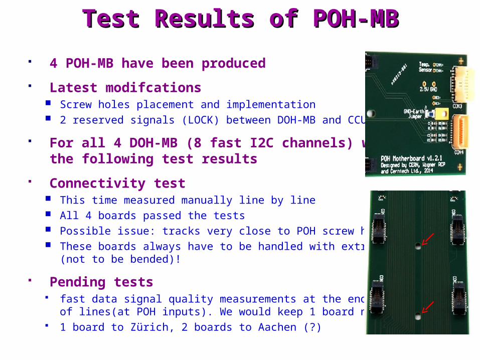
4 POH-MB have been produced
Latest modifcations Screw holes placement and implementation 2 reserved signals (LOCK) between DOH-MB and CCU-ring
For all 4 DOH-MB (8 fast I2C channels) we have the following test results
Connectivity test This time measured manually line by line All 4 boards passed the tests Possible issue: tracks very close to POH screw holes These boards always have to be handled with extra care
(not to be bended)!
Pending tests fast data signal quality measurements at the end
of lines(at POH inputs). We would keep 1 board now. 1 board to Zürich, 2 boards to Aachen (?)

Adapter BoardsAdapter Boards
AB L1&L2 - bottom
AB L1&L2 - top
AB L3&L4 - bottom
AB L3&L4 - top
AB L1&L2 AB L3&L4

4 - 4 AB L1&L2 and AB L3&L4 have been produced
We have the following test results
Connectivity test This time it was measured manually line by line All AB L1&l2, and 3 / 4 of the AB L3&L4 passed the tests On 1 board we have a short circuit, not found yet not even with a microscope
it can be either under one of two connectors or inside the PCB
Low voltage (Vd and Va) voltage drop Important quantitative parameter of the AB and CB boards (just like of the
Extension Boards and modue cables): How we use up the voltage drop budget? See results in next slides
Pending measurements No (Maybe more precise measurement of the GND plane resistance) AB boards have to be used in other pending measurements (fast I2C signal quality and
Sector C-D entire voltage drop) -> We keep 1+1 of them. 1+1 boards to Zürich, 2+2 boards to Aachen (?)
Test Results of Test Results of AB L1&L2 and AB L3&L4AB L1&L2 and AB L3&L4

AB and CB voltage drop simulations In the PCB design phase, post-layout simulations were made for the forward
Va and Vd connections iterating the „layout and routing” to minimize drop
Common ground plane for the return path: resistance was estimated
Both copper thickness, trace (plane) widthes, no. of layers (GND planes) are all limited We think that with the design efforts we went just to the wall.
AB and CB voltage drop measurements Originally we wanted to measure it through the AdpterBoard – ConnectorBoard chain
(or even a module cable included), and this is what we have to do (will do) as soon as we have all the boards.
Now we measured the AdapterBoards only with the aim of verifying the simulations
To get the whole voltage drop picture now, we have to rely on a mixture of mesuremenst, simulations, and estimations, however the AdapterBoards measurements can verify/correct the simulation results.
Sector C: VSector C: Vaa nd V nd Vdd voltage drop voltage drop
simulations and measurements simulations and measurements

Sector C: VSector C: Vaa nd V nd Vdd voltage drop voltage drop
simulations and measurements simulations and measurements
0,0
5,0
10,0
15,0
20,0
25,0
30,0
35,0
40,0
45,0
50,0
VA 1 VA 2 VA 3 VA 8 VA 9 VA 10 VD 1 VD 2 VD 3 VD 8 VD 9 VD 10
net
R
simulated
multimeter
scope - avg
sim / multim
sim / scope - avg
"1"
0,0
5,0
10,0
15,0
20,0
25,0
VA 4 VA 5 VA 6 VA 7 VA 11 VA 12 VA 13 VD 4 VD 5 VD 6 VD 7 VD 11 VD 12 VD 13
net
R
simulated
multimeter
scope - avg
sim / multim
sim / scope - avg
"1"
AB L1&L2 AB L3&L4

Sector C: VSector C: Vaa nd V nd Vdd voltage drop voltage drop

Pending IssuesPending Issues
CB boards production to be completed soon
Power cables to be designed and produced
Verfication of the implemented delays vs. the detector needs measure with the actual cable length distrubution
Only minor changes is possible
For the final production we need a scheduling for the deliver of the boards (input from Lea till the beginning of summer)
