prof. krishna r. pattipati prof. david l. kleinman
TRANSCRIPT

Copyright ©1994-2012 by K. Pattipati
Lecture 6
Prof. Krishna R. Pattipati
Prof. David L. Kleinman
Dept. of Electrical and Computer Engineering
University of Connecticut Contact: [email protected] (860) 486-2890
ECE 6095/4121
Digital Control of Mechatronic Systems
Actuators

Copyright ©1994-2012 by K. Pattipati
2
Actuators
• Actuator − A mechanical device for moving or controlling something
− Converts electrical/fluid/pneumatic/fuel energy into mechanical energy
• Continuous- and Incremental-Drive Actuators
• DC Motors …. used in precision position control applications
• Stepper Motors …. Digital actuator used in position control
applications
• Induction Motors (done in Lecture 1)
• Synchronous Motors
• Hydraulic Actuators
• Fluidics (Not discussed)
• Piezo Actuators (Not discussed)
used in high-power applications
(Not discussed)

Copyright ©1994-2012 by K. Pattipati
• Motors convert electrical energy to mechanical energy
• Motors make things move
Linear Motor
Electrostatic Moto
DC Brush Motor
Stepper Motor
Induction Motor
Universal Motor
Motors

Copyright ©1994-2012 by K. Pattipati
Typical Torque-speed curves
Torque, T
Speed, ω
Load
Operating
Points
DC Servo AC Servo
Stepper

Copyright ©1994-2012 by K. Pattipati
• DC Motor
− Most common actuator
− Converts electrical energy into mechanical energy
− Motors require more battery power (i.e., current) than electronics (e.g., CPU)
- e.g., 5 milliamps for the 68HC11 processor vs. 100 milliamps – 1 amp for a small
DC motor.
− Recall Torque armature current and steady-state torque-speed characteristics
of an armature controlled DC motor (constant field current, separately excited)
DC Motors
5
2
i A A
v
m T A f A
T v f
i Am
f f
v R i
K
T K i Ki i
K K Ki
v RT
Ki Ki
10
0
0
0
S
m
A
if
S
f
im
T
T
R
vKiTtorquestalling
Ki
vspeedloadNoT

Copyright ©1994-2012 by K. Pattipati
• Positioning (“Servo”) Applications
− Disk-drives, X-Y recorders, instruments, robots, sensor-pointing, fly-by-
wire/drive-by-wire inputs, fuel management,sunroof,…
• Speed Control Applications
− Fans, Drills, CNC machines, window wipers, lifts,…
• Power Range: Few Watts to a few kW
• Speed Range: few rpm to 10000rpm (use gear boxes)
• Time Constant: milli-seconds
• Often in-built encoders for position or tacho for speed
• Digital Control: Pulse-width-modulated (PWM) or Pulse-rate-modulated
(PRM)
• When to use a DC Motor?
− Accurate position/velocity control
− Low noise
• Limitations: expensive, regular maintenance, heavy
DC Motors
6

Copyright ©1994-2012 by K. Pattipati
DC Motor Servo and Drive/Control
7
• DC Servomotor
• DC Motor Drive/Control
Motor Selection to Match a Load

Copyright ©1994-2012 by K. Pattipati
DC Motor Data - 1
8
• Mechanical data − Peak torque (e.g., 65 N.m)
− Continuous stall torque (e.g., 25 N.m)
− Friction torque (e.g., 0.4 N.m)
− Maximum acceleration at peak torque (e.g., 33´103 rad/s2 )
− Maximum speed or no-load speed (e.g., 3,000 rpm.)
− Rated speed or speed at rated load (e.g., 2,400 rpm.)
− Rated output power (e.g., 5100 W)
− Rotor moment of inertia (e.g., 0.002 kg/m2 )
− Dimensions and weight (e.g., 14 cm diameter, 30 cm length, 20 kg)
− Allowable axial load or thrust (e.g., 230 N)
− Allowable radial load (e.g., 700 N)
− Mechanical (viscous) damping constant (e.g., 0.12 N.m/krpm)
− Mechanical time constant (e.g., 100 ms)
• Electrical data − Electrical time constant (e.g., 2 ms)
− Torque constant (e.g., 0.9 N.m/A for peak current or 1.2 N.m/A rms current)
− Back emf constant (e.g., 0.95 V/rad/s for peak voltage)
− Armature/field resistance and inductance (e.g., 1.0 , 2 mH)
− Compatible drive unit data (voltage, current, etc.)
• General data − Brush life and motor life (e.g., 5x10⁸ revolutions at maximum speed)
− Operating temperature and other environmental conditions (e.g., 0 to 40 °C)
− Thermal resistance (e.g., 1.5 °C/W)
− Thermal time constant (e.g., 70 minutes)
− Mounting configuration

Copyright ©1994-2012 by K. Pattipati
DC Motor Data - 2
Copyright ©1994-2012 by K. Pattipati
Drive Amplifier and Power Supply Selection
10
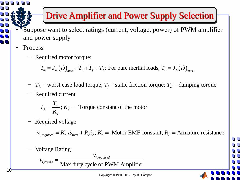
• Suppose want to select ratings (current, voltage, power) of PWM amplifier
and power supply
• Process
− Required motor torque:
− TL = worst case load torque; Tf = static friction torque; Td = damping torque
− Required current
− Required voltage
− Voltage Rating
max
; For pure inertial loads, m m L f d L LmaxT J T T T T J
; Torque constant of the motormA T
T
TI K
K
, max ; Motor EMF constant; Armature resistancei required e A A e Av K R i K R
,
,Max duty cycle of PWM Amplifier
i required
i rating
vv

Copyright ©1994-2012 by K. Pattipati
• For a GR12 C motor, determine the terminal voltage (vi ) for GR12C DC
motor to produce a torque of 75 Ncm at 2000 rpm.
DC Motor Analysis Example
11
75 ; 1.16*2 2.32 ; 4.2
81.52
81.527.55
10.8
0.95*7.55209.33 29.77
(11.3 /104.67)
Load d f
m Load d f
m T A A
ii
T Ncm T Ncm T Ncm
T T T T Ncm
T K i i A
vv V

Copyright ©1994-2012 by K. Pattipati
Series DC Motors - 1
12
2
( ) ( )
' ' '
( )
' '
i A F A i A F
A A
mm A A
i A F
m
v R R i v R R
K i K i K
TT Ki i
K
v R RK
K T K
Speed of a series motor is
inversely proportional to
the square root of Torque.
Nearly constant power is
possible.
• Series DC motors have armature and field winding in series
− Field current = Armature current
• No load speed is infinite
• Speed regulation is poor
• Starting torque and low speed operation are
satisfactory
Tm

Copyright ©1994-2012 by K. Pattipati
Series DC Motors - 2
13
2 2
2
30,000 , 120
250
30,000358.1
/ sec (800 / 60).2
358.10.0249 /
(120)
200 , 89.62
22.4
A
A
mA
A
PowerMotor current I Amps
Voltage
PowerTorque Nm
Speed in rad
Torque K I K Nm A
TWith the new load torque of Nm I Amps
K
Input power VI
06
22,406/ sec 112.03 / sec
200
112.03*2 1070.3 / sec
kW
PowerSpeed in rad rad
Torque
Speed in rpm rad
• Example
− 30kW mechanical power and 250 V supply. Speed is 800 rpm.
− If load torque is reduced to 200 Nm, what is the new speed?
Copyright ©1994-2012 by K. Pattipati
Shunt DC Motors
14
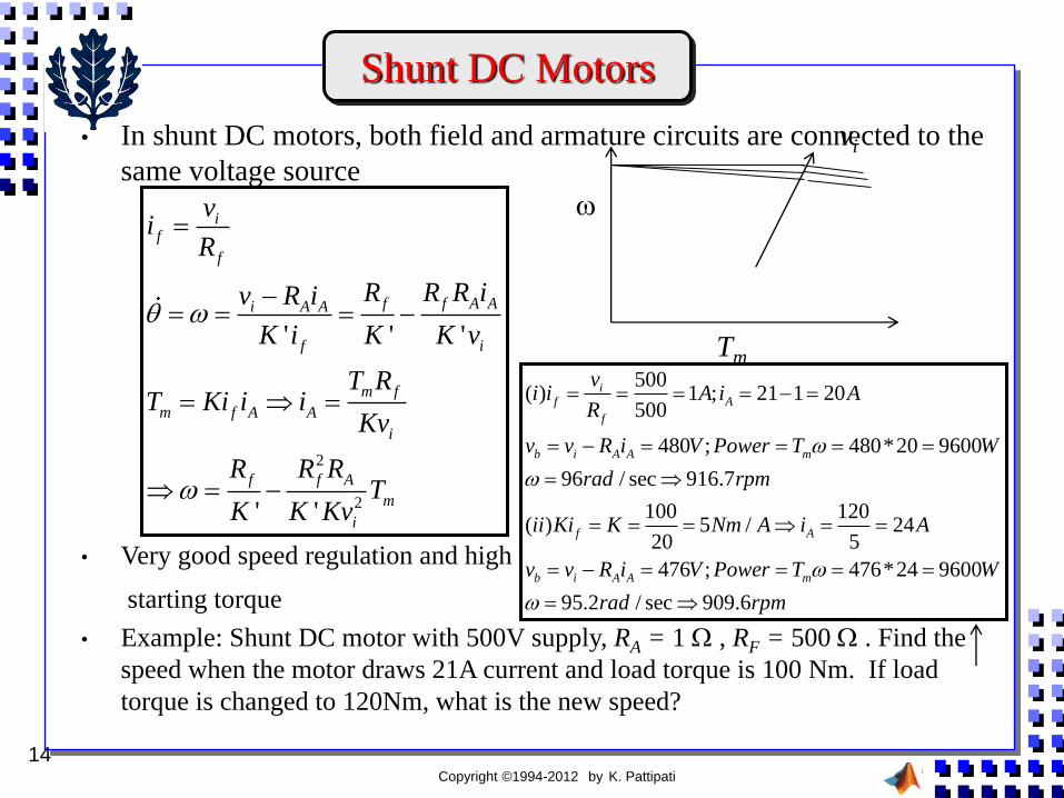
• In shunt DC motors, both field and armature circuits are connected to the
same voltage source
• Very good speed regulation and high
starting torque
• Example: Shunt DC motor with 500V supply, RA = 1 , RF = 500 . Find the
speed when the motor draws 21A current and load torque is 100 Nm. If load
torque is changed to 120Nm, what is the new speed?
2
2
' ' '
' '
if
f
f f A Ai A A
f i
m f
m f A A
i
f f A
m
i
vi
R
R R R iv R i
K i K K v
T RT Ki i i
Kv
R R RT
K K Kv
Tm
vi
500( ) 1 ; 21 1 20
500
480 ; 480*20 9600
96 / sec 916.7
100 120( ) 5 / 24
20 5
476 ; 476*24 9600
95.2 / sec 909.6
if A
f
b i A A m
f A
b i A A m
vi i A i A
R
v v R i V Power T W
rad rpm
ii Ki K Nm A i A
v v R i V Power T W
rad rpm

Copyright ©1994-2012 by K. Pattipati
Compound DC Motors
15
• In compound DC motors, part of field winding is in series (Rf1) and the
rest is in parallel (Rf2)
1 2
2
1
2
2
2
2
2 2 2
2
1
2 2
2
( )
' ' '
10 4
2
2 ( ) 4
'
if f f A
f
i A f A f f A A
f i
im f A m A A
f
i m i i mA A A
f f f
i i mi A f
f f
i
f
vi i i i
R
v R R i R R R i
K i K K v
vT Ki i T Ki K i
R
v T v v Ti i i
R K R R K
v v Tv R R
R R K
vK
R
2
2
4i m
f
v T
R K
Provides trade-off in
Performance between
series and shunt DC
motor s
Copyright ©1994-2012 by K. Pattipati
Stepper Motors
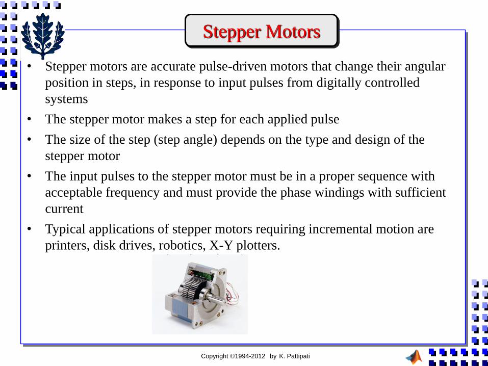
• Stepper motors are accurate pulse-driven motors that change their angular
position in steps, in response to input pulses from digitally controlled
systems
• The stepper motor makes a step for each applied pulse
• The size of the step (step angle) depends on the type and design of the
stepper motor
• The input pulses to the stepper motor must be in a proper sequence with
acceptable frequency and must provide the phase windings with sufficient
current
• Typical applications of stepper motors requiring incremental motion are
printers, disk drives, robotics, X-Y plotters.

Copyright ©1994-2012 by K. Pattipati
• So, Stepper Motors
− Are driven in fixed angular steps
− Each rotation step = rotor response to an input pulse (or a digital command)
• Three Basic Types
− Variable reluctance stepper motors (have soft iron core; single/multi-stack)
− Permanent Magnet stepper motors (have magnetized rotors)
− Hybrid stepper motors (have two stacks of rotor teeth forming the two
poles of a permanent magnet located along the rotor axis).
Stepper Motor Basics
Variable Reluctance
(single stack)
3-stack VR stepper motor 2-pole PM stepper motor

Copyright ©1994-2012 by K. Pattipati
• VR Stepper Motor
− Small step sizes
− Typically smaller torque
• PM Stepper Motor
− Larger step sizes (30-90 degrees)
− Have higher inertia and slower acceleration
− More torque per ampere of stator current than VR stepper motor
• Hybrid Stepper Motor
− Smaller step sizes
− More torque than VR stepper motor
− Natural choice for applications requiring small step length and high torque
− More expensive than a VR stepper motor
When do you use which Stepper Motor?

Copyright ©1994-2012 by K. Pattipati
• Rotor is a magnetic bar that pivots about
its center
• Each loop forms an electromagnet with
different polarity
• If we apply a voltage to loop 2 such that
pole piece A is South and B is North (it
must be because of the way they are
wound), the rotor magnet will line up as
shown. This is called holding position
• If we remove the voltage from the second
loop and apply it to the first loop, pole
pieces A and B will have no magnetic
attraction and pole pieces C and D will
have
• The rotor will turn, so the magnet will
take up a new position and be rotated 90
degrees clock wise
Basic Stepper Motor Concepts

Copyright ©1994-2012 by K. Pattipati
Full-stepping Sequence for a 3- VR Stepper Motor

Copyright ©1994-2012 by K. Pattipati
Half-stepping Sequence for a 2- Stepper Motor
• If the stator has Ns poles, stator pole
pitch is 360/ Ns degrees
− Ns = 12 stator pitch = 300
• If number of rotor poles is Nr,
rotor pitch is 360/ Nr degrees
− Nr =16 rotor pitch = 22.50
• Step angle = 360 (1/ Ns - 1/ Nr )
• Number of phases = m; (Ns/m even)
• Need : 360/m Nr = 360 (1/ Ns - 1/ Nr )
+I1
1 1 1 1(1 )r s
r s r
N NmN N N m

Copyright ©1994-2012 by K. Pattipati
Hybrid Stepper Motor
• Rotor stack misalignment (1/4 pitch) in a hybrid stepper motor
• Schematically shows the state where phase 1 is off and phase 2 is on with N
polarity

Copyright ©1994-2012 by K. Pattipati
Micro-stepping
• Rotor stack misalignment (1/4 pitch) in a hybrid stepper motor
• Schematically shows the state where phase 1 is off and phase 2 is on with N
polarity

Copyright ©1994-2012 by K. Pattipati
Stepper Motor Spec Sheet

Copyright ©1994-2012 by K. Pattipati
Stepper Motor Drive System

Copyright ©1994-2012 by K. Pattipati
Stepper Motor Selection Example - 1
• Equivalent Inertia at Rotor of the Motor via overall Kinetic Energy 2 2
2 2
1 2
2 2
1 2
1 1 1 1( ) ( ) ( )
2 2 2 2
1( ) ( )
m mm g m g d s c L e m
e m g g d s c L
rKE J J J J J m m J
p p
rJ J J J J J m m
p p

Copyright ©1994-2012 by K. Pattipati
Stepper Motor Selection Example - 2
• Data
• From triangular speed profile:
• Max acceleration/deceleration
• Maximum angular acceleration/deceleration and max. velocity of motor
• Maximum Torque needed with a motor of efficiency,
-3 2
-6 2 -6 2
1 2
10 , 0.2 sec; 10 ; 5 ; 5 ,; 2.0x10 .
: 2 3; 50x10 . 200x10 .
80% (
c L d s
g g
d cm T r cm m kg m kg J J kg m
Two gear units p and J kg m and J kg m
Overall system efficiency for either g
)ear unit
max max
1 2 0.2 1 / sec
2 0.2
dd v T v m
T
2maxmax 10 / sec
( / 2)
va m
T
2max maxmax max 100 / sec ; 10 / sec
pa pvp rad p rad
r r
2 2
max1 2
1( ) ( )m m g g d s c L
parT J J J J J m m
p p r
p = 1 when no gears

Copyright ©1994-2012 by K. Pattipati
Stepper Motor Selection Example - 3
• Stepper Motor Specifications

Copyright ©1994-2012 by K. Pattipati
29
Stepper Motor Selection Example - 4
• Stepper Motor Performance Curves

Copyright ©1994-2012 by K. Pattipati
Stepper Motor Selection Example - 5
• No gear case (p = 1), Efficiency = 0.8
2 2max
max
) ( ) 0.002 0.002 0.1 (5 5) 100
125( 0.104 . ; 10 / sec 95.5 operating speed range: 0-95.5
m m d s c L m
m m
aT J J J r m m J
r
T J N m rad rpm rpm
• Note: Torque at 95.5 rpm is < starting torque for first two motors (see
speed-torque curves)
• In motor selection use the weakest point (i.e., lowest torque) in the
operating speed range
• Form the following table:
Note: Without a gear unit,
available motors cannot meet
system requirements.

Copyright ©1994-2012 by K. Pattipati
Stepper Motor Selection Example - 6
• Gear case (p = 2), Assume same efficiency = 0.8
• Form the following table:
2 2
max1 2
2
6 6
max
1. ( ) ( )
1 0.1 = 200. 50.10 (200.10 0.002 0.002) (5 5)
4 2
=200. 0.0261 250. 0.0261
191
m m g g d s c L
m
m m m
pa rT J J J J J m m
r p p
J
J T J
rpm
• With full stepping, step angle = 1.8o. Corresponding step in conveyor
motion = positioning resolution = (1.8/2)x(/180)x0.1 = 1.57x10⁻³ m
Select this motor.
Has 200 steps

Copyright ©1994-2012 by K. Pattipati
• Typical hydraulic control system
− Hydraulic fluid (mineral oil or oil in water emulsions) is pressurized using a
pump driven by an AC motor
− The oils have the desirable properties of self-lubrication, corrosion resistance,
good thermal properties, fire resistance, environmental friendliness, low
compressibility (high stiffness for good bandwidth)
− Power conversions (typically m = 0.9; h = 0.6)
− Flow rates in the range of 1,000 to 50,000 gal/min (Note: 1 gal/min = 3.76
L/min) and pressures from 500 to 5000 psi (Note: 1kPa=0.145 psi)
− Pressure from the pump is regulated and stabilized by a relief valve and an
accumulator
− A hydraulic valve provides a controlled supply of fluid into the actuator,
controlling both the flow rate (including direction) and the pressure
Hydraulic Control System - 1
( , ) ( , ) ( , )m hi v T Q P

Copyright ©1994-2012 by K. Pattipati
• Main components of a hydraulic control system
− Serve valve
− Hydraulic actuator
− Load
− Feedback control elements (sensors and compensation circuitry, servo
amplifier, valve actuator
• Valve (incremental changes)
• Hydraulic Actuator
• Load
Hydraulic Control System - 2
q cq k u k p
2
dy V dpq A
dt dt
2
2 L
d y dym b Ap f
dt dt

Copyright ©1994-2012 by K. Pattipati
Hydraulic Spool Valve
(a) A four-way spool valve, (b) An overlapped land, (c) An under-lapped land

Copyright ©1994-2012 by K. Pattipati
Hydraulic Actuator

Copyright ©1994-2012 by K. Pattipati
Advantages /Disdvantages of Hydraulic Actuators
• Advantages over Electric Motor Systems
− High pressures (e.g., 5,000 psi) Can provide very high forces (torques) at
high power levels simultaneously to several actuating locations (flexible)
− Quite stiff when viewed from load side (because a hydraulic medium is
mechanically stiffer than an electromagnetic medium)
− Heat generated at the load can be quickly transferred to another location away
from the load by the hydraulic fluid itself
− Self-lubricating Low friction in valves, cylinders, pumps, hydraulic motors,
etc.
− Safety considerations will be less (e.g., no possibility of spark generations
unlike motors with brush mechanisms)
• Disadvantages
− More nonlinear
− Noisier
− Synchronization of multi-actuator operations may be difficult
− More expensive and less portable