professional digital two-way radio …€¢ what maintenance procedures will help promote longer...
TRANSCRIPT
PROFESSIONAL DIGITAL TWO-WAY RADIO
MOTOTRBO™DM4400/DM4401NUMERIC DISPLAY MOBILEUSER GUIDE
EN FR IT ESDE PL RU ARTU

Co
nte
nts
English
i
Contents
This User Guide contains all the information you need
to use the MOTOTRBO Series Mobiles.
Important Safety Information . . . . . . . . . . . . . . . . . iii
Product Safety and RF Exposure Compliance . . .iii
Software Version . . . . . . . . . . . . . . . . . . . . . . . . . . . iii
Computer Software Copyrights . . . . . . . . . . . . . . . iv
Getting Started . . . . . . . . . . . . . . . . . . . . . . . . . . . . . . 1
How to Use This Guide . . . . . . . . . . . . . . . . . . . . . . . 1
What Your Dealer/System Administrator
Can Tell You . . . . . . . . . . . . . . . . . . . . . . . . . . . . . . 1
Powering Up the Radio . . . . . . . . . . . . . . . . . . . . . . . 2
Adjusting the Volume . . . . . . . . . . . . . . . . . . . . . . . . 2
Identifying Radio Controls . . . . . . . . . . . . . . . . . . . . 3
Radio Controls . . . . . . . . . . . . . . . . . . . . . . . . . . . . . 3
Programmable Buttons . . . . . . . . . . . . . . . . . . . . . . . 4
Assignable Radio Functions . . . . . . . . . . . . . . . . . 4
Assignable Settings/Utility Functions . . . . . . . . . . . 5
Push-To-Talk (PTT) Button . . . . . . . . . . . . . . . . . . . . 5
Switching Between Conventional Analog and
Digital Mode . . . . . . . . . . . . . . . . . . . . . . . . . . . . . . . 6
Using the Volume/Channel Knob . . . . . . . . . . . . . . . 6
IP Site Connect . . . . . . . . . . . . . . . . . . . . . . . . . . . . 7
Capacity Plus . . . . . . . . . . . . . . . . . . . . . . . . . . . . . . 7
Linked Capacity Plus . . . . . . . . . . . . . . . . . . . . . . . . 8
Identifying Status Indicators . . . . . . . . . . . . . . . . . . . 9
LED Indicators . . . . . . . . . . . . . . . . . . . . . . . . . . . . . 9
Indicator Tones . . . . . . . . . . . . . . . . . . . . . . . . . . . . 10
Audio Tones . . . . . . . . . . . . . . . . . . . . . . . . . . . . . . 10
Receiving and Making Calls . . . . . . . . . . . . . . . . . . 11
Selecting a Zone . . . . . . . . . . . . . . . . . . . . . . . . . . . 11
Selecting a Channel . . . . . . . . . . . . . . . . . . . . . . . . 12
Receiving and Responding to a Radio Call . . . . . . 12
Receiving and Responding to a Group Call . . . . . 13
Receiving and Responding to a Private Call . . . 13
Receiving an All Call . . . . . . . . . . . . . . . . . . . . . . 14
Receiving and Responding to a Selective Call . . 14
Making a Radio Call . . . . . . . . . . . . . . . . . . . . . . . . 15
Making a Group Call . . . . . . . . . . . . . . . . . . . . . . 15
Making a Private Call . . . . . . . . . . . . . . . . . . . . . 16
Making an All Call . . . . . . . . . . . . . . . . . . . . . . . . 16
Making a Selective Call . . . . . . . . . . . . . . . . . . . . 17
Stopping a Radio Call . . . . . . . . . . . . . . . . . . . . . . 17
Talkaround . . . . . . . . . . . . . . . . . . . . . . . . . . . . . . . 18
Permanent Monitor . . . . . . . . . . . . . . . . . . . . . . . . . 18
Co
nte
nts
English
ii
Advanced Features . . . . . . . . . . . . . . . . . . . . . . . . . 19
Scan Lists . . . . . . . . . . . . . . . . . . . . . . . . . . . . . . . . 19
Scan . . . . . . . . . . . . . . . . . . . . . . . . . . . . . . . . . . . . 19
Starting and Stopping Scan . . . . . . . . . . . . . . . . 20
Responding to a Transmission During a Scan . . 20
Deleting a Nuisance Channel . . . . . . . . . . . . . . . 21
Restoring a Nuisance Channel . . . . . . . . . . . . . . 21
Vote Scan . . . . . . . . . . . . . . . . . . . . . . . . . . . . . . . . 21
Call Indicator Settings . . . . . . . . . . . . . . . . . . . . . . 21
Escalating Alarm Tone Volume . . . . . . . . . . . . . . 21
Call Alert Operation . . . . . . . . . . . . . . . . . . . . . . . . 22
Receiving and Responding to a Call Alert . . . . . 22
Making a Call Alert with
the One Touch Access Button . . . . . . . . . . . . . . 22
Emergency Operation . . . . . . . . . . . . . . . . . . . . . . 22
Sending an Emergency Alarm . . . . . . . . . . . . . . 23
Sending an Emergency Alarm with Call . . . . . . . 23
Sending an Emergency Alarm with Voice to
Follow . . . . . . . . . . . . . . . . . . . . . . . . . . . . . . . . . 24
Reinitiating an Emergency Mode . . . . . . . . . . . . 25
Exiting an Emergency Mode . . . . . . . . . . . . . . . . 25
Text Messaging Features . . . . . . . . . . . . . . . . . . . 26
Sending a Quick Text Message . . . . . . . . . . . . . 26
Privacy . . . . . . . . . . . . . . . . . . . . . . . . . . . . . . . . . . 27
Multi-Site Controls . . . . . . . . . . . . . . . . . . . . . . . . . 28
Starting an Automatic Site Search . . . . . . . . . . . 28
Stopping an Automatic Site Search . . . . . . . . . . 28
Starting a Manual Site Search . . . . . . . . . . . . . . 28
Lone Worker . . . . . . . . . . . . . . . . . . . . . . . . . . . . . . 29
Password Lock Features . . . . . . . . . . . . . . . . . . . . 29
Accessing the Radio from Password . . . . . . . . . 29
Unlocking the Radio from Locked State . . . . . . . 30
Bluetooth . . . . . . . . . . . . . . . . . . . . . . . . . . . . . . . . 30
Finding and Connecting to a Bluetooth Device . . 31
Disconnecting from a Bluetooth Device . . . . . . . 31
Switching Audio Route . . . . . . . . . . . . . . . . . . . . 31
Utilities . . . . . . . . . . . . . . . . . . . . . . . . . . . . . . . . . . 32
Setting the Squelch Level . . . . . . . . . . . . . . . . . 32
Setting the Power Level . . . . . . . . . . . . . . . . . . . 32
Turning the Option Board Feature(s) On or Off . 32
Turning the Voice Operating Transmission (VOX)
Feature On or Off . . . . . . . . . . . . . . . . . . . . . . . . 32
Turning the Public Address System On or Off . . 33
Turning the External Public Address System On
or Off . . . . . . . . . . . . . . . . . . . . . . . . . . . . . . . . . . 33
Turning Horns/Lights On or Off . . . . . . . . . . . . . . 33
Turning Radio Tones/Alerts On or Off . . . . . . . . 34
Voice Announcement . . . . . . . . . . . . . . . . . . . . . 34
Limited Warranty . . . . . . . . . . . . . . . . . . . . . . . . . . . 35
Imp
orta
nt S
afe
ty In
form
atio
n
English
iii
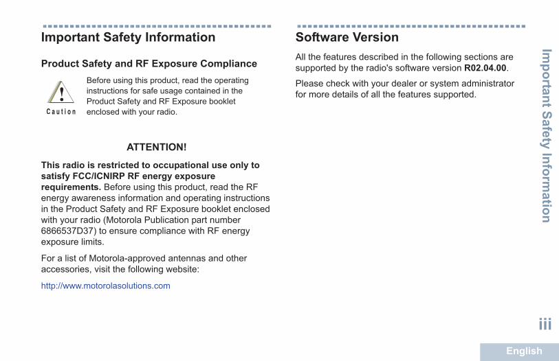
Important Safety Information
Product Safety and RF Exposure Compliance
ATTENTION!
This radio is restricted to occupational use only to
satisfy FCC/ICNIRP RF energy exposure
requirements. Before using this product, read the RF
energy awareness information and operating instructions
in the Product Safety and RF Exposure booklet enclosed
with your radio (Motorola Publication part number
6866537D37) to ensure compliance with RF energy
exposure limits.
For a list of Motorola-approved antennas and other
accessories, visit the following website:
http://www.motorolasolutions.com
Software Version
All the features described in the following sections are
supported by the radio's software version R02.04.00.
Please check with your dealer or system administrator
for more details of all the features supported.
Before using this product, read the operating
instructions for safe usage contained in the
Product Safety and RF Exposure booklet
enclosed with your radio.
Co
mp
ute
r S
oft
wa
re C
op
yri
gh
ts
English
iv
Computer Software Copyrights
The Motorola products described in this manual may
include copyrighted Motorola computer programs stored
in semiconductor memories or other media. Laws in the
United States and other countries preserve for Motorola
certain exclusive rights for copyrighted computer
programs including, but not limited to, the exclusive right
to copy or reproduce in any form the copyrighted
computer program. Accordingly, any copyrighted
Motorola computer programs contained in the Motorola
products described in this manual may not be copied,
reproduced, modified, reverse-engineered, or distributed
in any manner without the express written permission of
Motorola. Furthermore, the purchase of Motorola
products shall not be deemed to grant either directly or by
implication, estoppel, or otherwise, any license under the
copyrights, patents or patent applications of Motorola,
except for the normal non-exclusive license to use that
arises by operation of law in the sale of a product.
The AMBE+2TM voice coding Technology embodied in
this product is protected by intellectual property rights
including patent rights, copyrights and trade secrets of
Digital Voice Systems, Inc.
This voice coding Technology is licensed solely for use
within this Communications Equipment. The user of this
Technology is explicitly prohibited from attempting to
decompile, reverse engineer, or disassemble the Object
Code, or in any other way convert the Object Code into a
human-readable form.
U.S. Pat. Nos. #5,870,405, #5,826,222, #5,754,974,
#5,701,390, #5,715,365, #5,649,050, #5,630,011,
#5,581,656, #5,517,511, #5,491,772, #5,247,579,
#5,226,084 and #5,195,166.

Ge
tting
Sta
rted
English
1
Getting Started
Take a moment to review the following:
How to Use This Guide . . . . . . . . . . . . . . . . . . . . . . . . . page 1
What Your Dealer/System Administrator Can Tell You . page 1
Powering Up the Radio . . . . . . . . . . . . . . . . . . . . . . . . . page 2
Adjusting the Volume. . . . . . . . . . . . . . . . . . . . . . . . . . . page 2
How to Use This Guide
This User Guide covers the basic operation of the MOTOTRBO
Mobiles with Numeric Display.
However, your dealer or system administrator may have
customized your radio for your specific needs. Check with your
dealer or system administrator for more information.
Throughout this publication, the icons below are used to
indicate features supported in either the conventional Analog
mode or conventional Digital mode:
For features that are available in both Analog and Digital
modes, no icon is shown.
For features that are available in a conventional multi-site
mode, see IP Site Connect on page 7 for more information.
Selected features are also available on the single-site trunking
mode, Capacity Plus. See Capacity Plus on page 7 for more
information.
Selected features are also available in the multi-site trunking
mode, Linked Capacity Plus. See Linked Capacity Plus on
page 8 for more information.
What Your Dealer/System Administrator Can Tell You
You can consult your dealer or system administrator about the
following:
• Is your radio programmed with any preset conventional
channels?
• Which buttons have been programmed to access other
features?
• What optional accessories may suit your needs?
• What are the best radio usage practices for effective
communication?
• What maintenance procedures will help promote longer radio
life?
Indicates a conventional Analog Mode-Only feature.
Indicates a conventional Digital Mode-Only feature.

Gett
ing
Sta
rted
English
2
Powering Up the Radio
Press the On/Off
Button briefly.
The green LED blinks
and the numeric
display screen lights
up.
A brief tone sounds,
indicating that the
power up test is
successful.
NOTE: There is no
power up tone if the radio tones/alerts function is
disabled (see Turning Radio Tones/Alerts On or Off
on page 34).
If your radio does not power up, contact your dealer.
To turn off the radio, press and hold the On/Off Button.
NOTE: Your radio may take up to 7 seconds to completely turn
off.
Adjusting the Volume
To increase the volume, turn the Volume/Channel Knob
clockwise.
To decrease the volume, turn this knob counterclockwise.
NOTE: Your radio can be programmed to have a minimum
volume offset where the volume level cannot be turned
past the programmed minimum volume. Check with
your dealer or system administrator for more
information.
On/Off Button
Volume/Channel Knob

Ide
ntify
ing
Ra
dio
Co
ntro
ls
English
3
Identifying Radio Controls
Take a moment to review the following:
Radio Controls. . . . . . . . . . . . . . . . . . . . . . . . . . . . . . . . page 3
Programmable Buttons . . . . . . . . . . . . . . . . . . . . . . . . . page 4
Push-To-Talk (PTT) Button . . . . . . . . . . . . . . . . . . . . . . page 5
Switching Between Conventional Analog and
Digital Mode. . . . . . . . . . . . . . . . . . . . . . . . . . . . . . . . page 6
IP Site Connect . . . . . . . . . . . . . . . . . . . . . . . . . . . . . . . page 7
Capacity Plus. . . . . . . . . . . . . . . . . . . . . . . . . . . . . . . . . page 7
Linked Capacity Plus . . . . . . . . . . . . . . . . . . . . . . . . . . . page 8
Radio Controls
On/Off Button
Volume/Channel Knob
Display
Speaker
Front Programmable Buttons*
Accessory Connector
LED Indicators
P4
1 2 3
467 5
1
2
3
4
5
6
7
Ide
nti
fyin
g R
ad
io C
on
tro
ls
English
4
Programmable Buttons
Your dealer can program the programmable buttons as
shortcuts to radio functions or up to a maximum of six (6)
preset channels/groups depending on the duration of a button
press:
• Short press – Pressing and releasing rapidly.
• Long press – Pressing and holding for the programmed
duration.
• Hold down – Keeping the button pressed.
NOTE: The programmed duration of a button press is
applicable for all assignable radio/utility functions or
settings. See Emergency Operation on page 22 for
more information on the programmed duration of the
Emergency button.
Assignable Radio Functions
BluetoothTM Audio Switch – Toggles audio routing between
internal radio speaker and external Bluetooth-enabled
accessory.
Emergency – Depending on the programming, initiates or
cancels an Emergency alarm or call.
Ext PA On/Off – Toggles the audio routing between the
connected public address (PA) loudspeaker amplifier and the
radio’s internal public address (PA) system.
Manual Site Roam*‡ – Starts the manual site search.
Mic AGC On/Off – Toggles the internal microphone automatic
gain control (AGC) on or off. Not applicable during a Bluetooth
session.
Nuisance Channel Delete*‡ – Temporarily removes an
unwanted channel, except for the Selected Channel, from the
scan list. The Selected Channel refers to the user’s selected
zone/channel combination from which scan is initiated.
One Touch Access – Directly initiates a predefined Private
or Group Call, a Call Alert or a Quick Text message, or returns
the user to a preset channel.
Option Board Feature – Toggles option board feature(s) on or
off for option board-enabled channels.
PA On/Off – Toggles the radio’s internal public address (PA)
system on or off.
Permanent Monitor*‡– Monitors a selected channel for all
radio traffic until function is disabled.
Privacy – Toggles privacy on or off.
* Not applicable in Capacity Plus‡ Not applicable in Linked Capacity Plus
Ide
ntify
ing
Ra
dio
Co
ntro
ls
English
5
Repeater/Talkaround*‡ – Toggles between using a repeater
and communicating directly with another radio.
Scan*‡ – Toggles scan on or off.
Site Lock On/Off* – Toggles the automatic site roam on or
off.
Telemetry Control – Controls the Output Pin on a local or
remote radio.
Transmit Interrupt Remote Dekey – Stops an ongoing
interruptible call to free the channel.
Voice Operating Transmission (VOX) – Toggles VOX on or
off.
Zone – Allows selection from a list of zones.
Assignable Settings/Utility Functions
All Tones/Alerts – Toggles all tones on or off.
Channel Up/Down – Depending on the programming, changes
channel to previous or next channel.
Power Level – Toggles transmit power level between high and
low.
Squelch – Toggles squelch level between normal and tight.
Push-To-Talk (PTT) Button
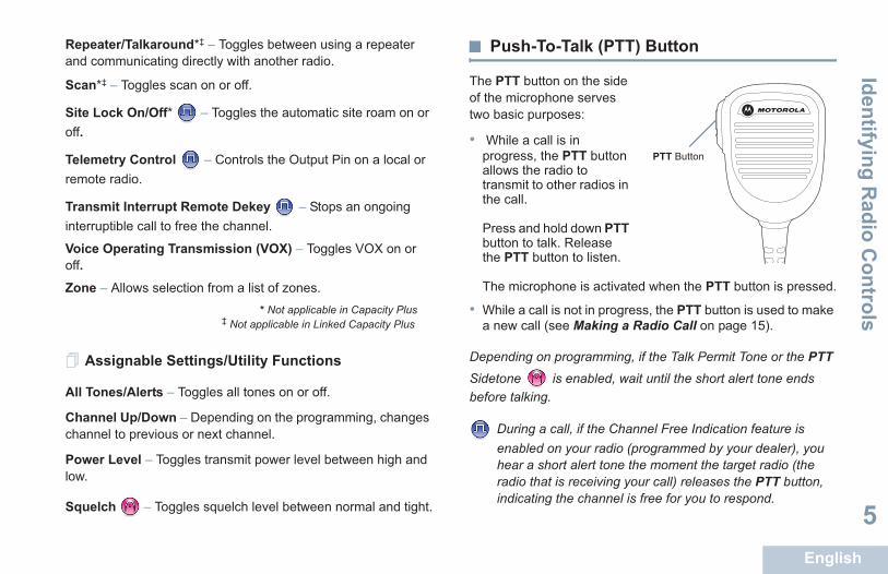
The PTT button on the side
of the microphone serves
two basic purposes:
• While a call is in
progress, the PTT button allows the radio to transmit to other radios in the call.
Press and hold down PTT button to talk. Release the PTT button to listen.
The microphone is activated when the PTT button is pressed.
• While a call is not in progress, the PTT button is used to make
a new call (see Making a Radio Call on page 15).
Depending on programming, if the Talk Permit Tone or the PTT
Sidetone is enabled, wait until the short alert tone ends
before talking.
During a call, if the Channel Free Indication feature is
enabled on your radio (programmed by your dealer), you
hear a short alert tone the moment the target radio (the
radio that is receiving your call) releases the PTT button,
indicating the channel is free for you to respond.
* Not applicable in Capacity Plus‡ Not applicable in Linked Capacity Plus
PTT Button
Ide
nti
fyin
g R
ad
io C
on
tro
ls
English
6
You will also hear a continuous talk prohibit tone, if your
call is interrupted, indicating that you should release the
PTT button, for example when the radio receives an
Emergency Call.
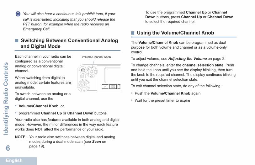
Switching Between Conventional Analog
and Digital Mode
Each channel in your radio can be
configured as a conventional
analog or conventional digital
channel.
When switching from digital to
analog mode, certain features are
unavailable.
To switch between an analog or a
digital channel, use the
• Volume/Channel Knob, or
• programmed Channel Up or Channel Down buttons
Your radio also has features available in both analog and digital
mode. However, the minor differences in the way each feature
works does NOT affect the performance of your radio.
NOTE: Your radio also switches between digital and analog
modes during a dual mode scan (see Scan on
page 19).
To use the programmed Channel Up or Channel
Down buttons, press Channel Up or Channel Down
to select the required channel.
Using the Volume/Channel Knob
The Volume/Channel Knob can be programmed as dual
purpose for both volume and channel or as a volume-only
control.
To adjust volume, see Adjusting the Volume on page 2.
To change channels, enter the channel selection state. Push
and hold the knob until you see the display blinking, then turn
the knob to the required channel. The display continues blinking
until you exit the channel selection state.
To exit channel selection state, do any of the following.
• Push the Volume/Channel Knob again
• Wait for the preset timer to expire
Volume/Channel Knob
Ide
ntify
ing
Ra
dio
Co
ntro
ls
English
7
IP Site Connect
This feature allows your radio to extend conventional
communication beyond the reach of a single site, by connecting
to different available sites which are connected via an Internet
Protocol (IP) network.
When the radio moves out of range from one site and into the
range of another, it connects to the new site's repeater to send
or receive calls/data transmissions. Depending on your settings,
this is done automatically or manually.
If the radio is set to do this automatically, it scans through all
available sites when the signal from the current site is weak or
when the radio is unable to detect any signal from the current
site. It then locks on to the repeater with the strongest Received
Signal Strength Indicator (RSSI) value.
In a manual site search, the radio searches for the next site in
the roam list that is currently in range (but which may not have
the strongest signal) and locks on to it.
NOTE: Each channel can only have either Scan or Roam
enabled, not both at the same time.
Channels with this feature enabled can be added to a particular
roam list. The radio searches the channel(s) in the roam list
during the automatic roam operation to locate the best site.
A roam list supports a maximum of 16 channels (including the
Selected Channel).
NOTE: You cannot manually add or delete an entry to the roam
list. Check with your dealer or system administrator for
more information.
Capacity Plus
Capacity Plus is a single-site trunking configuration of the
MOTOTRBO radio system, which uses a pool of channels to
support hundreds of users and up to 254 Groups. This feature
allows your radio to efficiently utilize the available number of
programmed channels while in Repeater Mode.
You hear a negative indicator tone if you try to access a feature
not applicable to Capacity Plus via a programmable button
press.
Your radio also has features that are available in conventional
digital mode, IP Site Connect, Capacity Plus and Linked
Capacity Plus. However, the minor differences in the way each
feature works does NOT affect the performance of your radio.
Check with your dealer or system administrator for more
information on this configuration.

Ide
nti
fyin
g R
ad
io C
on
tro
ls
English
8
Linked Capacity Plus
Linked Capacity Plus is a multi-site multi-channel trunking
configuration of the MOTOTRBO radio system, combining the
best of both Capacity Plus and IP Site Connect configurations.
Linked Capacity Plus allows your radio to extend trunking
communication beyond the reach of a single site, by connecting
to different available sites which are connected via an Internet
Protocol (IP) network. It also provides an increase in capacity by
efficiently utilizing the combined available number of
programmed channels supported by each of the available sites.
When the radio moves out of range from one site and into the
range of another, it connects to the new site's repeater to send
or receive calls/data transmissions. Depending on your settings,
this is done automatically or manually.
If the radio is set to do this automatically, it scans through all
available sites when the signal from the current site is weak or
when the radio is unable to detect any signal from the current
site. It then locks on to the repeater with the strongest Received
Signal Strength Indicator (RSSI) value.
In a manual site search, the radio searches for the next site in
the roam list that is currently in range (but which may not have
the strongest signal) and locks on to it.
Any channel with Linked Capacity Plus enabled can be added
to a particular roam list. The radio searches these channels
during the automatic roam operation to locate the best site.
NOTE: You cannot manually add or delete an entry to the
roam list. Check with your dealer or system
administrator for more information.
Similar to Capacity Plus, icons of features not applicable to
Linked Capacity Plus are not available in the menu. You hear a
negative indicator tone if you try to access a feature not
applicable to Linked Capacity Plus via a programmable button
press.
Check with your dealer or system administrator for more
information on this configuration.
Ide
ntify
ing
Sta
tus
Ind
ica
tors
English
9
Identifying Status Indicators
Your radio indicates its operational status through the following:
LED Indicators . . . . . . . . . . . . . . . . . . . . . . . . . . . . . . . . page 9
Audio Tones. . . . . . . . . . . . . . . . . . . . . . . . . . . . . . . . . page 10
Indicator Tones . . . . . . . . . . . . . . . . . . . . . . . . . . . . . . page 10
LED Indicators
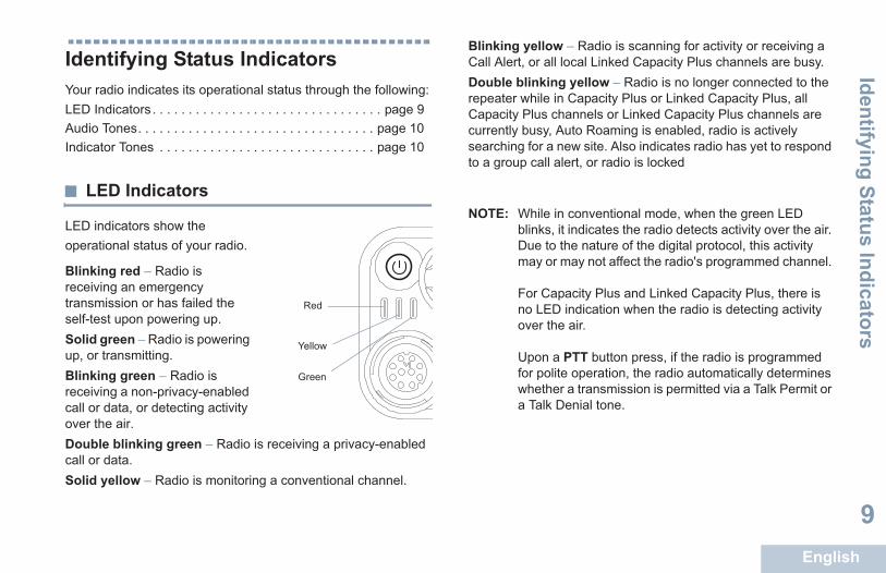
LED indicators show the
operational status of your radio.
Blinking red – Radio is
receiving an emergency
transmission or has failed the
self-test upon powering up.
Solid green – Radio is powering
up, or transmitting.
Blinking green – Radio is
receiving a non-privacy-enabled
call or data, or detecting activity
over the air.
Double blinking green – Radio is receiving a privacy-enabled
call or data.
Solid yellow – Radio is monitoring a conventional channel.
Blinking yellow – Radio is scanning for activity or receiving a
Call Alert, or all local Linked Capacity Plus channels are busy.
Double blinking yellow – Radio is no longer connected to the
repeater while in Capacity Plus or Linked Capacity Plus, all
Capacity Plus channels or Linked Capacity Plus channels are
currently busy, Auto Roaming is enabled, radio is actively
searching for a new site. Also indicates radio has yet to respond
to a group call alert, or radio is locked
NOTE: While in conventional mode, when the green LED
blinks, it indicates the radio detects activity over the air.
Due to the nature of the digital protocol, this activity
may or may not affect the radio's programmed channel.
For Capacity Plus and Linked Capacity Plus, there is
no LED indication when the radio is detecting activity
over the air.
Upon a PTT button press, if the radio is programmed
for polite operation, the radio automatically determines
whether a transmission is permitted via a Talk Permit or
a Talk Denial tone.
Red
Yellow
Green

Ide
nti
fyin
g S
tatu
s I
nd
ica
tors
English
10
Indicator Tones
High pitched tone Low pitched tone
Audio Tones
Alert tones provide you with audible indications of the radio’s
status or the radio’s response to data received.
Positive Indicator Tone
Negative Indicator Tone
Continuous Tone A monotone sound. Sounds
continuously until termination.
Periodic Tone Sounds periodically depending on the
duration set by the radio. Tone starts,
stops, and repeats itself.
Repetitive Tone A single tone that repeats itself until it is
terminated by the user.
Momentary Tone Sounds only once for a short period of
time defined by the radio.
Re
ce
ivin
g a
nd
Ma
kin
g C
alls
English
11
Receiving and Making Calls
Once you understand how your MOTOTRBO Mobile is
configured, you are ready to use your radio.
Use this navigation guide to familiarize yourself with the basic
Call features:
Selecting a Zone . . . . . . . . . . . . . . . . . . . . . . . . . . . . . page 11
Selecting a Radio Channel, Subscriber ID,
or Group ID . . . . . . . . . . . . . . . . . . . . . . . . . . . . . . . page 12
Receiving and Responding to a Radio Call . . . . . . . . . page 12
Making a Radio Call . . . . . . . . . . . . . . . . . . . . . . . . . . page 15
Stopping a Radio Call . . . . . . . . . . . . . . . . . . . . . . . . . page 17
Talkaround. . . . . . . . . . . . . . . . . . . . . . . . . . . . . . . . . . page 18
Permanent Monitor . . . . . . . . . . . . . . . . . . . . . . . . . . . page 18
Selecting a Zone
A zone is a group of channels. Your radio supports up to a
maximum of 2 zones, with a maximum of 99 channels per zone.
Procedure:
1 Press the programmed Zone button.
2 You hear a positive indicator tone, indicating the radio has
switched from Zone 1 to Zone 2.
OR
You hear a negative indicator tone, indicating the radio has
switched from Zone 2 to Zone 1.
Re
ce
ivin
g a
nd
Ma
kin
g C
all
s
English
12
Selecting a Channel
Transmissions are sent and received on a channel. Depending
on your radio's configuration, each channel may have been
programmed differently to support different groups of users or
supplied with different features. After selecting the required
zone, select the channel you require to transmit or receive on.
Procedure:
Once the required zone is set (if you have multiple zones in
your radio), use the Volume/Channel Knob in channel
selection state to select the number that represents the
required channel.
OR
Press the programmed Channel Up or Channel Down
button to select the number that represents the required
channel.
OR
Press the programmed One Touch Access button to select
the preset channel assigned to the button.
See Selecting a Zone on page 11 for more information on
selecting your required zone.
Receiving and Responding to a Radio Call
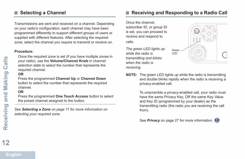
Once the channel,
subscriber ID, or group ID
is set, you can proceed to
receive and respond to
calls.
The green LED lights up
while the radio is
transmitting and blinks
when the radio is
receiving.
NOTE: The green LED lights up while the radio is transmitting
and double blinks rapidly when the radio is receiving a
privacy-enabled call.
To unscramble a privacy-enabled call, your radio must
have the same Privacy Key, OR the same Key Value
and Key ID (programmed by your dealer) as the
transmitting radio (the radio you are receiving the call
from).
See Privacy on page 27 for more information.
Green LED

Re
ce
ivin
g a
nd
Ma
kin
g C
alls
English
13
Receiving and Responding to a Group Call
To receive a call made to a group of users, your radio must be
configured as part of that group.
Procedure:
When you receive a Group Call:
1 The green LED blinks. Your radio unmutes and the incoming
call sounds through the radio's speaker.
If the Channel Free Indication feature is enabled, you
hear a short alert tone the moment the transmitting radio
releases the PTT button, indicating the channel is free for
you to respond.
Press the PTT button to respond to the call.
OR
If the Voice Interrupt feature is enabled, press the PTT
button to stop the current call from the transmitting radio and
free the channel for you to talk/respond.
2 The green LED lights up.
3 Wait for the Talk Permit Tone to finish (if enabled) and speak
clearly into the microphone.
OR
Wait for the PTT Sidetone to finish (if enabled) and
speak clearly into the microphone.
4 Release the PTT button to listen.
5 If there is no voice activity for a predetermined period of
time, the call ends.
See Making a Group Call on page 15 for details on making a
Group Call.
Receiving and Responding to a Private Call
A Private Call is a call from an individual radio to another
individual radio.
Procedure:
When you receive a private call:
1 The green LED blinks. Your radio unmutes and the incoming
call sounds through the radio's speaker.
2 If the Channel Free Indication feature is enabled, you hear a
short alert tone the moment the transmitting radio releases
the PTT button, indicating the channel is free for you to
respond.
Press the PTT button to respond to the call.
OR
If the Voice Interrupt feature is enabled, press the PTT
button to stop the current call from the transmitting radio and
free the channel for you to talk/respond.
3 The green LED lights up.
4 Wait for the Talk Permit Tone to finish (if enabled) and speak
clearly into the microphone.
Re
ce
ivin
g a
nd
Ma
kin
g C
all
s
English
14
5 Release the PTT button to listen.
6 If there is no voice activity for a predetermined period of
time, the call ends.
7 You hear a short tone.
See Making a Private Call on page 16 for more details on
making a private call.
Receiving an All Call
An All Call is a call from an individual radio to every radio on the
channel. It is used to make important announcements requiring
the user’s full attention.
Procedure:
When you receive an All Call:
1 A tone sounds and the green LED blinks. Your radio
unmutes and the incoming call sounds through the radio's
speaker.
2 Once the All Call ends, the radio returns to the previous
screen before receiving the call. An All Call does not wait for
a predetermined period of time before ending.
If the Channel Free Indication feature is enabled, you
hear a short alert tone the moment the transmitting radio
releases the PTT button, indicating the channel is now
available for use.
You cannot respond to an All Call.
NOTE: The radio stops receiving the All Call if you switch to a
different channel while receiving the call.
During an All Call, you are not able to use any
programmed button functions until the call ends.
Receiving and Responding to a Selective Call
A Selective Call is a call from an individual radio to another
individual radio. It is a Private Call on an analog system.
Procedure:
When you receive a Selective Call:
1 The green LED blinks. Your radio unmutes and the incoming
call sounds through the radio's speaker.
2 If the Channel Free Indication feature is enabled, you hear a
short alert tone the moment the transmitting radio releases
the PTT button, indicating the channel is free for you to
respond.
Press the PTT button to respond to the call.
3 The LED lights up solid green.
4 Wait for the Talk Permit Tone to finish (if enabled) and speak
clearly into the microphone.
5 Release the PTT button to listen.
6 If there is no voice activity for a predetermined period of
time, the call ends.

Re
ce
ivin
g a
nd
Ma
kin
g C
alls
English
15
7 You hear a short tone.
See Making a Selective Call on page 17 for details on making
a Selective Call.
Making a Radio Call
After selecting your channel, you can select a subscriber alias
or ID, or group alias or ID by using:
• Volume/Channel Knob
• A programmed One Touch Access button
NOTE: Your radio must have the Privacy feature enabled on
the channel to send a privacy-enabled transmission.
Only target radios with the same Privacy Key OR the
same Key Value and Key ID as your radio is are able to
unscramble the transmission.
See Privacy on page 27 for more information.
The One Touch Access feature allows you to make a
Group, or Private Call to a predefined ID easily. This
feature can be assigned to a short or long
programmable button press.You can ONLY have one
ID assigned to a One Touch Access button. Your
radio can have multiple One Touch Access buttons
programmed.
Making a Group Call
To make a call to a group of users, your radio must be
configured as part of that group.
Procedure:
1 Select the channel with the active group alias or ID. See
Selecting a Channel on page 12.
OR
Press the programmed One Touch Access button.
2 Press the PTT button to make the call. The green LED lights
up.
3 Wait for the Talk Permit Tone to finish (if enabled) and speak
clearly into the microphone.
OR
Wait for the PTT Sidetone to finish (if enabled) and
speak clearly into the microphone.
4 Release the PTT button to listen. When the target radio
responds, the green LED blinks.
5 If the Channel Free Indication feature is enabled, you
hear a short alert tone the moment the target radio releases
the PTT button, indicating the channel is free for you to
respond. Press the PTT button to respond.
OR
If there is no voice activity for a predetermined period of
time, the call ends.

Re
ce
ivin
g a
nd
Ma
kin
g C
all
s
English
16
Making a Private Call
While you can receive and/or respond to a Private Call initiated
by an authorized individual radio, your radio
must be programmed for you to initiate a Private Call.
There are two types of Private Calls. The first type, where a
radio presence check is performed prior to setting up the call,
while the other sets up the call immediately.
Only one of these call types can be programmed to your radio
by your dealer.
You hear a negative indicator tone, when you make a Private
Call via the One Touch Access button or the Scroll Up/Down
buttons, if this feature is not enabled.
Use the Quick Text Message or Call Alert features to contact an
individual radio. See Text Messaging Features on page 26 or
Call Alert Operation on page 22 for more information.
Procedure:
1 Select the channel with the active radio alias or ID. See
Selecting a Channel on page 12.
OR
Press the programmed One Touch Access button.
2 Press the PTT button to make the call. The green LED lights
up.
3 Wait for the Talk Permit Tone to finish (if enabled) and speak
clearly into the microphone.
4 Release the PTT button to listen. When the target radio
responds, the green LED blinks.
5 If the Channel Free Indication feature is enabled, you hear a
short alert tone the moment the target radio releases the
PTT button, indicating the channel is free for you to respond.
Press the PTT button to respond.
OR
If there is no voice activity for a predetermined period of
time, the call ends.
6 You hear a short tone.
Making an All Call
This feature allows you to transmit to all users on the channel.
Your radio must be programmed to allow you to use this feature.
Procedure:
1 Select the channel with the active group alias or ID. See
Selecting a Channel on page 12.
2 Press the PTT button to make the call. The green LED lights
up.
3 Wait for the Talk Permit Tone to finish (if enabled) and speak
clearly into the microphone.
OR
Wait for the PTT Sidetone to finish (if enabled) and
speak clearly into the microphone.

Re
ce
ivin
g a
nd
Ma
kin
g C
alls
English
17
Users on the channel cannot respond to an All Call.
Making a Selective Call
Just like a Private Call, while you can receive and/or respond to
a Selective Call initiated by an authorized individual radio, your
radio must be programmed for you to initiate a Selective Call.
Procedure:
1 Select the channel with the active group alias or ID. See
Selecting a Channel on page 12.
2 Press the PTT button to make the call. The green LED lights
up.
3 Wait for the Talk Permit Tone to finish (if enabled) and speak
clearly into the microphone.
4 Release the PTT button to listen. When the target radio
responds, the green LED blinks.
5 If the Channel Free Indication feature is enabled, you hear a
short alert tone the moment the target radio releases the
PTT button, indicating the channel is free for you to respond.
Press the PTT button to respond.
OR
If there is no voice activity for a predetermined period of
time, the call ends.
6 You hear a short tone.
Stopping a Radio Call
This feature allows you to stop an ongoing Group or Private Call
to free the channel for transmission. For example, when a radio
experiences a “stuck microphone” condition where the PTT
button is inadvertently pressed by the user.
Your radio must be programmed to allow you to use this feature.
Procedure:
While on the required channel:
1 Press the programmed Transmit Interrupt Remote Dekey
button.
2 Wait for acknowledgment.
3 The radio sounds a positive indicator tone, indicating that
the channel is now free.
OR
The radio sounds a negative indicator tone, indicating that
the radio is unable to free the channel.
Your radio sounds a negative indicator tone until you release
the PTT button, if it is transmitting an interruptible call that is
stopped via this feature. On an interrupted radio with a display,
the display shows Call Interrupted.

Re
ce
ivin
g a
nd
Ma
kin
g C
all
s
English
18
Talkaround
You can continue to communicate when your repeater is not
operating, or when your radio is out of the repeater’s range but
within talking range of other radios. This is called “talkaround”.
NOTE: This feature is not applicable in Capacity Plus and
Linked Capacity Plus.
Procedure:
1 Press the programmed Repeater/Talkaround button.
2 You hear a positive indicator tone, indicating the radio is in
Talkaround mode.
OR
You hear a negative indicator tone, indicating the radio is in
Repeater mode.
The Talkaround setting is retained even after powering down.
Permanent Monitor
Use the Permanent Monitor feature to continuously monitor a
selected channel for activity.
NOTE: This feature is not applicable in Capacity Plus and
Linked Capacity Plus.
Procedure:
1 Press the programmed Permanent Monitor button.
2 Radio sounds alert tone, and the yellow LED lights up.
3 Press the programmed Permanent Monitor button to
remove the radio from permanent monitor mode.
4 Radio sounds an alert tone and the yellow LED turns off.
Ad
va
nc
ed
Fe
atu
res
English
19
Advanced Features
Use this navigation guide to learn more about advanced
features available with your radio:
Scan Lists . . . . . . . . . . . . . . . . . . . . . . . . . . . . . . . . . . page 19
Scan . . . . . . . . . . . . . . . . . . . . . . . . . . . . . . . . . . . . . . page 19
Call Indicator Settings . . . . . . . . . . . . . . . . . . . . . . . . . page 21
Call Alert Operation . . . . . . . . . . . . . . . . . . . . . . . . . . . page 22
Emergency Operation . . . . . . . . . . . . . . . . . . . . . . . . . page 22
Text Messaging Features . . . . . . . . . . . . . . . . . . . . . . page 26
Privacy. . . . . . . . . . . . . . . . . . . . . . . . . . . . . . . . . . . . . page 27
Multi-Site Controls . . . . . . . . . . . . . . . . . . . . . . . . . . . . page 28
Lone Worker . . . . . . . . . . . . . . . . . . . . . . . . . . . . . . . . page 29
Password Lock Features . . . . . . . . . . . . . . . . . . . . . . . page 29
Bluetooth . . . . . . . . . . . . . . . . . . . . . . . . . . . . . . . . . . . page 30
Utilities . . . . . . . . . . . . . . . . . . . . . . . . . . . . . . . . . . . . . page 32
Scan Lists
Scan lists are created and assigned to individual channels/
groups. Your radio scans for voice activity by cycling through the
channel/group sequence specified in the scan list for the current
channel.
Your radio supports up to 250 scan lists, with a maximum of 16
members in a list. Each scan list shall support a mixture of both
analog and digital entries.
NOTE: This feature is not applicable in Capacity Plus and
Linked Capacity Plus.
Scan
When you start a scan, your radio cycles through the
programmed scan list for the current channel looking for voice
activity. The yellow LED blinks.
During a dual mode scan, if you are on a digital channel, and
your radio locks onto an analog channel, it automatically
switches from digital mode to analog mode for the duration of
the call. This is also true for the reverse.

Ad
va
nc
ed
Fe
atu
res
English
20
There are two types of scans:
• Main Channel Scan (Manual): Your radio scans all the
channels/groups in your scan list. On entering scan, your radio may – depending on the settings – automatically start on the last scanned “active” channel/group or on the channel where scan was initiated.
• Auto Scan (Automatic): Your radio automatically starts
scanning when you select a channel/group that has Auto Scan enabled.
NOTE: This feature is not applicable in Capacity Plus and
Linked Capacity Plus.
Starting and Stopping Scan
Procedure:
1 Press the programmed Scan button.
OR
Use the Volume/Channel Knob or Channel Up/Down
buttons to select a channel with Auto Scan enabled.
2 When Scan is enabled, the yellow LED blinks and you hear
a positive indicator tone.
OR
When Scan is disabled, the LED turns off and you hear a
negative indicator tone.
Responding to a Transmission During a Scan
During scanning, your radio stops on a channel/group where
activity is detected. The radio stays on that channel for a
programmed time period known as “hang time”.
Procedure:
1 If the Channel Free Indication feature is enabled, you
hear a short alert tone the moment the transmitting radio
releases the PTT button, indicating the channel is free for
you to respond.
2 Press the PTT button during hang time. The green LED
lights up.
3 Wait for the Talk Permit Tone to finish (if enabled) and speak
clearly into the microphone.
OR
Wait for the PTT Sidetone to finish (if enabled) and
speak clearly into the microphone.
4 Release the PTT button to listen.
5 If you do not respond within the hang time, the radio returns
to scanning other channels/groups.
Ad
va
nc
ed
Fe
atu
res
English
21
Deleting a Nuisance Channel
If a channel continually generates unwanted calls or noise
(termed a “nuisance” channel), you can temporarily remove the
unwanted channel from the scan list.
This capability does not apply to the channel designated as the
Selected Channel.
Procedure:
1 When your radio “locks on to” an unwanted or nuisance
channel, press the programmed Nuisance Channel Delete
button until you hear a tone.
2 Release the Nuisance Channel Delete button. The
nuisance channel is deleted.
Restoring a Nuisance Channel
Procedure:
To restore the deleted nuisance channel, do one of the
following:
• Turn the radio off and power it on again, OR
• Stop and restart a scan via the programmed Scan button, OR
• Change the channel via the Volume/Channel Knob or
Channel Up/Down buttons.
Vote Scan
Vote Scan provides you with wide area coverage in areas where
there are multiple base stations transmitting identical
information on different analog channels.
Your radio scans analog channels of multiple base stations and
performs a voting process to select the strongest received
signal. Once that is established, your radio unmutes to
transmissions from that base station.
The yellow LED blinks during Vote Scan.
To respond to a transmission during a Vote Scan, follow the
same procedures as Responding to a Transmission During a
Scan on page 20.
Call Indicator Settings
You can turn on or off the ringing tones for a received Private
Call (see Turning Radio Tones/Alerts On or Off on page 34).
Escalating Alarm Tone Volume
Your radio can be programmed by your dealer to continually
alert you when a radio call remains unanswered. This is done
by automatically increasing the alarm tone volume over time.
This feature is known as Escalert.

Ad
va
nc
ed
Fe
atu
res
English
22
Call Alert Operation
Call Alert paging enables you to alert a specific radio user to call
you back when they are able to do so.
This feature is accessible via a programmed One Touch
Access button.
Receiving and Responding to a Call AlertProcedure:
When you receive a Call Alert page:
1 You hear a repetitive tone. The yellow LED blinks.
2 Press the PTT button within four (4) seconds of receiving a
Call Alert page to respond to the Private Call.
Making a Call Alert with the One Touch Access
Button
Procedure:
1 Press the programmed One Touch Access button to make
a Call Alert to the predefined ID.
2 The green LED lights up when your radio is sending the Call
Alert.
3 If the Call Alert acknowledgement is received, two chirps
sound.
OR
If the Call Alert acknowledgement is not received, a low-
pitched tone sounds.
Emergency Operation
An Emergency Alarm is used to indicate a critical situation. You
are able to initiate an Emergency at any time, in any state, even
when there is activity on the current channel.
Your dealer can set the duration of a button press for the
programmed Emergency button, except for long press, which is
similar with all other buttons:
• Short press – Between 0.05 seconds and 0.75 seconds
• Long press – Between 1.00 second and 3.75 seconds
The Emergency button is assigned with the Emergency On/ Off
feature. Check with your dealer for the assigned operation of
the Emergency button.
If short press the Emergency button is assigned to turn on the
Emergency mode, then long press the Emergency button is
assigned to exit the Emergency mode.
If long press the Emergency button is assigned to turn on the
Emergency mode, then short press the Emergency button is
assigned to exit the Emergency mode.
Your radio supports three Emergency Alarms:
• Emergency Alarm
• Emergency Alarm with Call
• Emergency Alarm with Voice to Follow

Ad
va
nc
ed
Fe
atu
res
English
23
In addition, each alarm has the following types:
• Regular – Radio transmits an alarm signal and shows audio
and/or visual indicators.
• Silent – Radio transmits an alarm signal without any audio or
visual indicators. Radio receives calls without any sound through the radio’s speaker, until you press the PTT button to initiate the call.
• Silent with Voice – Radio transmits an alarm signal without
any audio or visual indicators, but allow incoming calls to sound through the radio’s speaker.
Only one of the Emergency Alarms above can be assigned to
the programmed Emergency button or the Emergency
footswitch.
Sending an Emergency Alarm
This feature allows you to send an Emergency Alarm, a non-
voice signal, which triggers an alert indication on a group of
radios.
Procedure:
1 Press the programmed Emergency On button or the
Emergency footswitch.
2 The green LED lights up.
3 When an Emergency Alarm acknowledgment is received,
the Emergency tone sounds. The green LED blinks.
OR
If your radio does not receive an Emergency Alarm
acknowledgement, and after all retries have been
exhausted, a low-pitched tone sounds.
4 Radio exits the Emergency Alarm mode.
If your radio is set to Silent, it does not display any audio or
visual indicators during Emergency mode.
Sending an Emergency Alarm with Call
This feature allows you to send an Emergency Alarm to a group
of radios. Upon acknowledgement by a radio within the group,
the group of radios can communicate over a programmed
Emergency channel.
Procedure:
1 Press the programmed Emergency On button or press the
Emergency footswitch.
2 The green LED lights up.
3 When an Emergency Alarm acknowledgment is received,
the Emergency tone sounds. The green LED blinks.
4 Press the PTT button to make the call. The green LED lights
up.

Ad
va
nc
ed
Fe
atu
res
English
24
5 Wait for the Talk Permit Tone to finish (if enabled) and speak
clearly into the microphone.
OR
Wait for the PTT Sidetone to finish (if enabled) and
speak clearly into the microphone.
6 Release the PTT button to listen.
7 When the channel is free for you to respond, a short alert
tone sounds ( if the Channel Free Indication feature is
enabled). Press the PTT button to respond.
OR
Once your call ends, press the programmed Emergency
Off button to exit the Emergency mode.
If your radio is set to Silent, it does not display any audio or
visual indicators during Emergency mode, or allow any received
calls to sound through the radio’s speaker, until you press the
PTT button to initiate the call.
If your radio is set to Silent with Voice, it does not display any
audio or visual indicators during Emergency mode, but allow
incoming calls to sound through the radio’s speaker. The
indicators only appear once you press the PTT button to initiate,
or respond to, the call.
Sending an Emergency Alarm with Voice to
Follow
This feature allows you to send an Emergency Alarm to a group
of radios. Your radio’s microphone is automatically activated,
allowing you to communicate with the group of radios without
pressing the PTT button.
This activated microphone state is also known as “hot mic”.
If your radio has Emergency Cycle Mode enabled, repetitions of
hot mic and receiving period are made for a programmed
duration.
NOTE: During Emergency Cycle Mode, received calls sound
through the radio’s speaker.
If you press the PTT button during the programmed receiving
period, you will hear a prohibit tone, indicating that you should
release the PTT. The radio ignores the PTT press and remains
in Emergency mode.
NOTE: If you press the PTT button during hot mic, and
continue to press it after the hot mic duration expires,
the radio continues to transmit until you release the
PTT button.
Procedure:
1 Press the programmed Emergency On button or the
Emergency footswitch.
Ad
va
nc
ed
Fe
atu
res
English
25
2 The green LED lights up.
3 Once a tone sounds, speak clearly into the microphone.
When hot mic has been enabled, the radio automatically
transmits without a PTT press until the hot mic duration
expires.
While transmitting, the green LED lights up.
4 The radio automatically stops transmitting when:
Once the cycling duration between hot mic and receiving
calls expires, if Emergency Cycle Mode is enabled.
OR
Once the hot mic duration expires, if Emergency Cycle
Mode is disabled.
5 To transmit again, press the PTT button.
OR
Press the programmed Emergency Off button to exit the
Emergency mode.
6 Once the hot mic duration expires, the radio automatically
stops transmitting. To transmit again, press the PTT button.
If your radio is set to Silent, it does not display any audio or
visual indicators during Emergency mode, or allow any received
calls to sound through the radio’s speaker, until the
programmed hot mic transmission period is over, and you press
the PTT button.
If your radio is set to Silent with Voice, it does not display any
audio or visual indicators during Emergency mode when you
are making the call with hot mic, but allow sound through the
radio’s speaker when the target radio responds after the
programmed hot mic transmission period is over. The indicators
only appear when you press the PTT button.
NOTE: If the Emergency Alarm request fails, the radio does
not retry to send the request, and enters the hot mic
state directly.
Reinitiating an Emergency Mode
NOTE: This feature is only applicable to the radio sending the
Emergency Alarm.
There are two instances where this can happen:
• You change the channel while the radio is in Emergency
mode. This exits the Emergency mode. If Emergency Alarm is enabled on this new channel, the radio reinitiates Emergency.
• You press the programmed Emergency On button during an
Emergency initiation/transmission state. This causes the radio to exit this state, and to reinitiate Emergency.
Exiting an Emergency Mode
NOTE: This feature is only applicable to the radio sending the
Emergency Alarm.
Your radio exits Emergency mode when one of the following
occurs:
• Emergency Alarm acknowledgement is received (for
Emergency Alarm only), OR

Ad
va
nc
ed
Fe
atu
res
English
26
• An Emergency Exit Telegram is received, OR
• All retries to send the alarm have been exhausted, OR
• The Emergency Off button is pressed.
NOTE: If your radio is powered off, it exits the Emergency
mode. The radio does not reinitiate the Emergency
mode automatically when it is turned on again.
Text Messaging Features
Sending a Quick Text Message
You can send Quick Text messages, programmed by your
dealer, via the programmable button.
Procedure:
1 Press the programmed One Touch Access button to send
a predefined Quick Text message to a predefined ID.
2 The green LED lights up.
3 Two chirps indicate that the message is sent successfully.
OR
A low-pitched tone indicates that the message cannot be
sent.

Ad
va
nc
ed
Fe
atu
res
English
27
Privacy
If enabled, this feature helps to prevent eavesdropping by
unauthorized users on a channel by the use of a software-
based scrambling solution. The signaling and user identification
portions of a transmission are not scrambled.
Your radio must have privacy enabled on the channel to send a
privacy-enabled transmission, although this is not a necessary
requirement for receiving a transmission. While on a privacy-
enabled channel, the radio is still able to receive clear
(unscrambled) transmissions.
Your radio supports two types of privacy:
• Basic Privacy
• Enhanced Privacy.
Only ONE of the privacy types above can be assigned to the
radio.
To unscramble a privacy-enabled call or data transmission, your
radio must be programmed to have the same Privacy Key (for
Basic Privacy), OR the same Key Value and Key ID (for
Enhanced Privacy) as the transmitting radio.
If your radio receives a scrambled call that is of a different
Privacy Key, OR a different Key Value and Key ID, you will
either hear a garbled transmission (Basic Privacy) or nothing at
all (Enhanced Privacy).
The LED lights up solid green while the radio is transmitting and
blinks green rapidly when the radio is receiving an ongoing
privacy-enabled transmission.
NOTE: Some radio models may not offer this Privacy feature.
Check with your dealer or system administrator for
more information.
Procedure:
Press the programmed Privacy button to toggle privacy on or
off.
Ad
va
nc
ed
Fe
atu
res
English
28
Multi-Site Controls
These features are applicable when your current radio channel
is part of an IP Site Connect or Linked Capacity Plus
configuration.
See IP Site Connect on page 7 and Linked Capacity Plus on
page 8 for more details about these configurations.
Starting an Automatic Site Search
NOTE: The radio only scans for a new site if the current signal
is weak or when the radio is unable to detect any signal
from the current site. If the RSSI value is strong, the
radio remains on the current site.
Procedure:
1 Press the programmed Site Lock On/Off button.
2 A tone sounds.
3 The yellow LED blinks rapidly when the radio is actively
searching for a new site, and turns off once the radio locks
on to a site.
The radio also performs an automatic site search (site is
unlocked) during a PTT button press or data transmission if the
current channel, a multi-site channel with an attached roam list,
is out of range.
Stopping an Automatic Site Search
When the radio is actively searching for a new site:
Procedure:
1 Press the programmed Site Lock On/Off button.
2 A tone sounds and the LED turns off.
Starting a Manual Site Search
Procedure:
1 Press the programmed Manual Site Roam button.
2 A tone sounds and the green LED blinks.
3 You hear a positive indicator tone and the LED turns off,
indicating the radio is locked on to a site.
OR
You hear a negative indicator tone and the LED turns off,
indicating the radio is unable to lock on to a site.
Ad
va
nc
ed
Fe
atu
res
English
29
Lone Worker
This feature prompts an emergency to be raised if there is no
user activity, such as any radio button press or activation of the
channel selector, for a predefined time.
Following no user activity for a programmed duration, the radio
pre-warns the user via an audio indicator once the inactivity
timer expires.
If there is still no acknowledgment by the user before the
predefined reminder timer expires, the radio initiates an
Emergency Alarm.
Only one of the following Emergency Alarms is assigned to this
feature:
• Emergency Alarm
• Emergency Alarm with Call
• Emergency Alarm with Voice to Follow
The radio remains in the emergency state allowing voice
messages to proceed until action is taken. See Emergency
Operation on page 22 on ways to exit Emergency.
This feature is limited to radios with this function enabled.
Check with your dealer or system administrator for more
information.
Password Lock Features
If enabled, this feature allows you to access your radio via
password upon powering up.
Accessing the Radio from Password
Procedure:
Power up the radio.
1 You hear a continuous tone.
2 Press the Scroll Up/Down buttons to select a digit and
Front Button P2 to enter the selected digit. Enter the
remaining digits of the password in the same manner.
3 When the last digit of the four-digit password is entered,
your radio automatically checks the validity of the password.
If the password is correct:
Your radio proceeds to power up. See Powering Up the
Radio on page 2.
OR
If the password is incorrect:
You hear a continuous tone. Repeat Steps 1 and 2.
OR
After the third incorrect password, your radio enters into
locked state. A tone sounds and the yellow LED double
blinks.
Your radio enters into locked state for 15 minutes, and responds
to inputs from On/Off button.
Ad
va
nc
ed
Fe
atu
res
English
30
NOTE: The radio is unable to receive any call, including
emergency calls, in locked state.
The use of Emergency footswitch cancels out
password input to access the radio.
Unlocking the Radio from Locked State
Procedure:
Wait for 15 minutes. Repeat Steps 1 to 3 in Accessing the
Radio from Password on page 29.
OR
Power up the radio, if you have powered down the radio during
locked state:
1 A tone sounds and the yellow LED double blinks.
2 Wait for 15 minutes. Repeat Steps 1 to 3 in Accessing the
Radio from Password on page 29.
Your radio restarts the 15 minutes timer for locked state when
you power up.
Bluetooth
This feature allows you to use your radio with a Bluetooth-
enabled device (accessory) via a Bluetooth connection. Your
radio supports both Motorola and Commercially available Off-
The-Shelf (COTS) Bluetooth-enabled devices.
Bluetooth operates within a range of 10 meters line of sight.
This is an unobstructed path between your radio and your
Bluetooth-enabled device.
It is not recommended that you leave your radio behind and
expect your Bluetooth-enabled device to work with a high
degree of reliability when they are separated.
At the fringe areas of reception, both voice and tone quality will
start to sound "garbled" or "broken". To correct this problem,
simply position your radio and Bluetooth-enabled device closer
to each other (within the 10-meter defined range) to re-establish
clear audio reception. Your radio’s Bluetooth function has a
maximum power of 2.5 mW (4 dBm) at the 10-meter range.
Your radio can support up to 3 simultaneous Bluetooth
connections with Bluetooth-enabled devices of unique types.
For example, a headset, a scanner, and a PTT-Only Device
(POD). Multiple connections with Bluetooth-enabled devices of
the same type are not supported.
Refer to your respective Bluetooth-enabled device’s user
manual for more details on your Bluetooth-enabled device’s full
capabilities.

Ad
va
nc
ed
Fe
atu
res
English
31
Finding and Connecting to a Bluetooth Device
Procedure:
1 Turn on your Bluetooth-enabled device and place it in
pairing mode. Refer to respective Bluetooth-enabled
device’s user manual.
2 On your radio, press the programmed Bluetooth Connect
button.
3 A tone sounds and LED blinks yellow.
4 Your Bluetooth-enabled device may require additional steps
to complete the pairing. Refer to respective Bluetooth-
enabled device’s user manual.
5 If successful, a positive tone sounds.
OR
If unsuccessful, a negative indicator tone sounds.
Do not turn off your Bluetooth-enabled device during the finding
and connecting operation as this cancels the operation.
Your radio connects to the Bluetooth-enabled device within
range with either the strongest signal strength, or to one which it
has connected to before in a prior session.
NOTE:A pin code may be required to be programmed in your
radio before it can pair with some devices. Contact
your dealer for more information.
Disconnecting from a Bluetooth Device
Procedure:
1 Press the programmed Bluetooth Disconnect button.
2 A positive indicator tone sounds when disconnected.
Switching Audio Route
You can toggle audio routing between internal radio speaker
and external Bluetooth-enabled accessory.
Procedure:
1 Press the programmed Bluetooth Audio Switch button.
2 A tone sounds when the audio route has switched.
Ad
va
nc
ed
Fe
atu
res
English
32
Utilities
Setting the Squelch Level
You can adjust your radio's squelch level to filter out unwanted
calls with low signal strength or channels that have a higher
than normal background noise.
Settings: Normal is the default. Tight filters out (unwanted)
calls and/or background noise. However, calls from remote
locations may also be filtered out.
Procedure:
1 Press the programmed Squelch button.
2 You hear a positive indicator tone, indicating the radio is
operating in tight squelch.
OR
You hear a negative indicator tone, indicating the radio is
operating in normal squelch.
Setting the Power Level
You can customize your radio’s power setting to high or low for
each channel.
Settings: High enables communication with radios located at a
considerable distance from you. Low enables communication
with radios in closer proximity.
Procedure:
1 Press the programmed Power Level button.
2 You hear a positive indicator tone, indicating the radio is
transmitting at low power.
OR
You hear a negative indicator tone, indicating the radio is
transmitting at high power.
Turning the Option Board Feature(s) On or Off
A channel can support up to 6 option board features. Refer to
your dealer or system administrator for more information.
Procedure:
Press the programmed Option Board Feature button to toggle
the feature on or off.
Turning the Voice Operating Transmission (VOX)
Feature On or Off
This feature allows you to initiate a hands-free voice activated
call on a programmed channel. The radio automatically
transmits, for a programmed period, whenever the microphone
on the VOX-capable accessory detects voice.
NOTE: You may need to turn off the radio and power it up
again after detaching the VOX-capable microphone
to allow the radio to switch to another valid accessory.
Ad
va
nc
ed
Fe
atu
res
English
33
Pressing the PTT button during radio operation disables VOX.
To re-enable VOX, do one of the following:
• Turn the radio off and power it on again, OR
• Change the channel via the Scroll Up/Down buttons, OR
• Change the channel via the Volume/Channel Knob, OR
• Follow the procedure below.
NOTE: Turning this feature on or off is limited to radios with
this function enabled. Check with your dealer or system
administrator for more information.
Procedure:
Press the programmed VOX button to toggle the feature on or
off.
If the Talk Permit Tone feature is enabled, use a trigger word to
initiate the call. Wait for the Talk Permit Tone to finish before
speaking clearly into the microphone.
Turning the Public Address System On or Off
You can enable and disable the radio’s internal public address
(PA) system.
Procedure:
Press the programmed PA On/Off button to toggle the feature
on or off.
Turning the External Public Address System On
or Off
You can enable or disable the audio routing between the
connected public address (PA) loudspeaker amplifier and the
radio’s internal public address (PA) system.
Procedure:
Press the programmed Ext PA On/Off button to toggle the
feature on or off.
Turning Horns/Lights On or Off
Your radio is able to notify you of an incoming call via the horns
and lights feature. When activated, an incoming call sounds
your vehicle's horn and turns on its lights.
This feature needs to be installed through your radio’s rear
accessory connector by your dealer.
Procedure:
1 Press the programmed Horns/Lights button.
2 You hear a positive indicator tone, indicating the horns and
lights feature is on.
OR
You hear a negative indicator tone, indicating the horns and
lights feature is off.
Ad
va
nc
ed
Fe
atu
res
English
34
Turning Radio Tones/Alerts On or Off
You can enable and disable all radio tones and alerts (except for
the incoming Emergency alert tone) if needed.
Procedure:
1 Press the programmed All Tones/Alerts button.
2 You hear a positive indicator tone, indicating all tones and
alerts are on.
OR
You hear a negative indicator tone, indicating all tones and
alerts are off.
Voice Announcement
This feature enables the radio to audibly indicate the current
Zone or Channel the user has just assigned, or programmable
button press. This audio indicator can be customized per
customer requirements. This is typically useful when the user is
in a difficult condition to read the content shown on the display.
Use the following features to toggle Voice Announcement on or
off.
Procedure:
Press the programmed Voice Announcement button.
Intelligent Audio
Your radio automatically adjusts its audio volume to overcome
current background noise in the environment, inclusive of both
stationary and non-stationary noise sources. This feature is a
Receive-only feature and does not affect Transmit audio.
NOTE: This feature is not applicable during a Bluetooth
session.
Use the following features to toggle Intelligent Audio on or off.
Procedure:
Press the programmed Intelligent Audio button to toggle the
feature on or off.
GPS
Global Positioning System (GPS) is a satellite navigation
system that determines the radio’s precise location.
Procedure:
Press the programmed GPS button to toggle the feature on or
off.

Lim
ited
Warra
nty
English
35
Limited Warranty
MOTOROLA COMMUNICATION PRODUCTS
I. WHAT THIS WARRANTY COVERS AND FOR HOW
LONG:
MOTOROLA SOLUTIONS, INC. (“MOTOROLA”) warrants the
MOTOROLA manufactured Communication Products listed below
(“Product”) against defects in material and workmanship under
normal use and service for a period of time from the date of
purchase as scheduled below:
MOTOROLA, at its option, will at no charge either repair the
Product (with new or reconditioned parts), replace it (with a new or
reconditioned Product), or refund the purchase price of the Product
during the warranty period provided it is returned in accordance
with the terms of this warranty. Replaced parts or boards are
warranted for the balance of the original applicable warranty period.
All replaced parts of Product shall become the property of
MOTOROLA.
This express limited warranty is extended by MOTOROLA to the
original end user purchaser only and is not assignable or
transferable to any other party. This is the complete warranty for the
Product manufactured by MOTOROLA. MOTOROLA assumes no
obligations or liability for additions or modifications to this warranty
unless made in writing and signed by an officer of MOTOROLA.
Unless made in a separate agreement between MOTOROLA and
the original end user purchaser, MOTOROLA does not warrant the
installation, maintenance or service of the Product.
MOTOROLA cannot be responsible in any way for any ancillary
equipment not furnished by MOTOROLA which is attached to or
used in connection with the Product, or for operation of the Product
with any ancillary equipment, and all such equipment is expressly
excluded from this warranty. Because each system which may use
the Product is unique, MOTOROLA disclaims liability for range,
coverage, or operation of the system as a whole under this
warranty.
II. GENERAL PROVISIONS:
This warranty sets forth the full extent of MOTOROLA'S
responsibilities regarding the Product. Repair, replacement or
refund of the purchase price, at MOTOROLA’s option, is the
exclusive remedy. THIS WARRANTY IS GIVEN IN LIEU OF ALL
OTHER EXPRESS WARRANTIES. IMPLIED WARRANTIES,
INCLUDING WITHOUT LIMITATION, IMPLIED WARRANTIES OF
MERCHANTABILITY AND FITNESS FOR A PARTICULAR
PURPOSE, ARE LIMITED TO THE DURATION OF THIS LIMITED
WARRANTY. IN NO EVENT SHALL MOTOROLA BE LIABLE FOR
DAMAGES IN EXCESS OF THE PURCHASE PRICE OF THE
PRODUCT, FOR ANY LOSS OF USE, LOSS OF TIME,
INCONVENIENCE, COMMERCIAL LOSS, LOST PROFITS OR
SAVINGS OR OTHER INCIDENTAL, SPECIAL OR
CONSEQUENTIAL DAMAGES ARISING OUT OF THE USE OR
DM Series Digital Mobile Radios Two (2) Years
Product Accessories One (1) Year
Lim
ite
d W
arr
an
ty
English
36
INABILITY TO USE SUCH PRODUCT, TO THE FULL EXTENT
SUCH MAY BE DISCLAIMED BY LAW.
III. STATE LAW RIGHTS:
SOME STATES DO NOT ALLOW THE EXCLUSION OR
LIMITATION OF INCIDENTAL OR CONSEQUENTIAL DAMAGES
OR LIMITATION ON HOW LONG AN IMPLIED WARRANTY
LASTS, SO THE ABOVE LIMITATION OR EXCLUSIONS MAY
NOT APPLY.
This warranty gives specific legal rights, and there may be other
rights which may vary from state to state.
IV. HOW TO GET WARRANTY SERVICE:
You must provide proof of purchase (bearing the date of purchase
and Product item serial number) in order to receive warranty
service and, also, deliver or send the Product item, transportation
and insurance prepaid, to an authorized warranty service location.
Warranty service will be provided by MOTOROLA through one of its
authorized warranty service locations. If you first contact the
company which sold you the Product (e.g., dealer or
communication service provider), it can facilitate your obtaining
warranty service.
V. WHAT THIS WARRANTY DOES NOT COVER:
A) Defects or damage resulting from use of the Product in other
than its normal and customary manner.
B) Defects or damage from misuse, accident, water, or neglect.
C)Defects or damage from improper testing, operation,
maintenance, installation, alteration, modification, or adjustment.
D)Breakage or damage to antennas unless caused directly by
defects in material workmanship.
E) A Product subjected to unauthorized Product modifications,
disassembles or repairs (including, without limitation, the addition
to the Product of non-MOTOROLA supplied equipment) which
adversely affect performance of the Product or interfere with
MOTOROLA's normal warranty inspection and testing of the
Product to verify any warranty claim.
F) Product which has had the serial number removed or made
illegible.
G)Rechargeable batteries if:
(1) any of the seals on the battery enclosure of cells are broken
or show evidence of tampering.
(2) the damage or defect is caused by charging or using the
battery in equipment or service other than the Product for which it
is specified.
H)Freight costs to the repair depot.
I) A Product which, due to illegal or unauthorized alteration of the
software/firmware in the Product, does not function in
accordance with MOTOROLA’s published specifications or the
FCC certification labeling in effect for the Product at the time the
Product was initially distributed from MOTOROLA.
J) Scratches or other cosmetic damage to Product surfaces that
does not affect the operation of the Product.
K) Normal and customary wear and tear.
Lim
ited
Warra
nty
English
37
VI. PATENT AND SOFTWARE PROVISIONS:
MOTOROLA will defend, at its own expense, any suit brought
against the end user purchaser to the extent that it is based on a
claim that the Product or parts infringe a United States patent, and
MOTOROLA will pay those costs and damages finally awarded
against the end user purchaser in any such suit which are
attributable to any such claim, but such defense and payments are
conditioned on the following:
A) that MOTOROLA will be notified promptly in writing by such
purchaser of any notice of such claim;
B) that MOTOROLA will have sole control of the defense of such
suit and all negotiations for its settlement or compromise; and
C)should the Product or parts become, or in MOTOROLA’s opinion
be likely to become, the subject of a claim of infringement of a
United States patent, that such purchaser will permit
MOTOROLA, at its option and expense, either to procure for
such purchaser the right to continue using the Product or parts or
to replace or modify the same so that it becomes non-infringing
or to grant such purchaser a credit for the Product or parts as
depreciated and accept its return. The depreciation will be an
equal amount per year over the lifetime of the Product or parts as
established by MOTOROLA.
MOTOROLA will have no liability with respect to any claim of patent
infringement which is based upon the combination of the Product or
parts furnished hereunder with software, apparatus or devices not
furnished by MOTOROLA, nor will MOTOROLA have any liability
for the use of ancillary equipment or software not furnished by
MOTOROLA which is attached to or used in connection with the
Product. The foregoing states the entire liability of MOTOROLA with
respect to infringement of patents by the Product or any parts
thereof.
Laws in the United States and other countries preserve for
MOTOROLA certain exclusive rights for copyrighted MOTOROLA
software such as the exclusive rights to reproduce in copies and
distribute copies of such MOTOROLA software. MOTOROLA
software may be used in only the Product in which the software was
originally embodied and such software in such Product may not be
replaced, copied, distributed, modified in any way, or used to
produce any derivative thereof. No other use including, without
limitation, alteration, modification, reproduction, distribution, or
reverse engineering of such MOTOROLA software or exercise of
rights in such MOTOROLA software is permitted. No license is
granted by implication, estoppel or otherwise under MOTOROLA
patent rights or copyrights.
VII. GOVERNING LAW:
This Warranty is governed by the laws of the State of Illinois, U.S.A.

Lim
ite
d W
arr
an
ty
English
38
Notes