professional portfolio v3
TRANSCRIPT

ROBERT HUBER//
PROFESSIONALPORTFOLIOPARALINEHOUSER WALKER ARCHITECTS

Project Name //
Architect //
Project Scope // Project Role //QUEST COMPLEX 2Approx. 5,000 sq ft office building to serve at the entry to organization complex, to serve as an administative headquarters for the organization. Under construciion.
Involved from conceptual through CD set, drawings have been ahead of schedule. Rendering and mod-eling through all stages of design. Participation in coordination meetings and involvement in materi-al/production selection.
PARALINE

DN
DN
ROCK STREET (30' RW)
JOSE
PH E
LOWE
RY BL
VD
ALLE
Y
EXISTING BUILDINGPARKING LOT OFNEIGHBORING PROPERTY
LANDSCAPE
BRICK ENTRY PLAZA
UPPER PLAZA
SIDEW
ALK
5' MIN. SIDEWALK
10' S
IDEWA
LK
5' LAN
DSCA
PE ST
RIP
LOWER PLAZA
LANDSCAPE
LANDSCAPE
LANDSCAPE
ENTRYENTRY
BACKFLOW PREVENTERVAULT - SEE CIVIL
FIRST FLOORPROPOSED BUILDING
PROPERTY LINE
©
SCOPE DOCUMENTS
The Construction Documents have not been completed therefore this drawing maybe incomplete or not coordinated. The documents issued indicate the generalscope of the Project. The Contractor is responsible for complete and coordinatedpricing and Work, and shall include all items necessary for the proper executionand completion of the Project, whether indicated or not. All components of theProject shall comply with any and all requirements of national, state, and localcodes. The Contractor shall inform the Owner and Architect of any omissions,inconsistencies or errors in the information provided. If no notice is given and anyomissions, inconsistencies or errors are discovered, the Architect's decisions onitems of Work included in the scope shall be binding on the Contractor, whenconsistent with the general scope and quality of the Project.
Principal-in-Charge
Project Manager
Project Architect
Staff Architect
Project No.
Date
Drawing No.
NOT ISSUED FOR CONSTRUCTION
1
A
2 3 4 5 6 7 8 9 10 11 12 13 14 15 16 17 18
1 2 3 4 5 6 7 8 9 10 11 12 13 14 15 16 17 18
BC
DE
FG
HJ
KL
MN
P
AB
CD
EF
GH
JK
LM
NP
Copyright Paraline 2016
115 MARTIN LUTHER KING JR DR SW, SUITE 410 ATLANTA, GEORGIA 30303
(P) 404.448.1039 WWW.PARALINESTUDIO.COM
4/25/2
0163
:41:50
P M
A010
ARCHITECTURAL SITE PLAN
QUEST COMPLEX 2
283 JOSEPH E. LOWERY BLVD NWATLANTA, GA 30314
QUEST COMMUNITY DEVELOPMENTORGANIZATION
PROJ
ECTN
AME:
QUES
TCO M
PLEX
2SH
E ETN
UMBE
R:A0
10-A
R CHIT
ECTU
RALS
ITEPL
A N
3/16" = 1'-0"1 ARCHITECTURAL SITE PLAN
ISSUANCESNo. Drawing Issue Description Date
1 SAP SUBMITTAL 12/21/15

Project Name //
Architect //
Project Scope // Project Role //
1
2
2.8
3
3.2
J K L M N N.1
140 SF
IDEATIONSTUDIO
G202
482 SF
FAB LABG203
87 SF
ASSESSMENTG207
148 SF
STORAGEG204
131 SF
ASSESSMENTG208
686 SF
OPEN OFFICEG206
CORRIDORF210
CORRIDORF211
17 SF
ELECG205
HOTEL DESKSBY OWNER
662 SF
DEMONSTRATIONAREA
G201
G203
G207
G208
G204
G205
D
E
A4021
A4023
A4027
NOT IN CONTRACT
0S3B
0S3B
1S6B-1
0S3B
0S3B
0S3B-1
1S6B-1C
C
G201A
0S3B-1
0S3A
EXISTING SERVICEELEVATOR
VESTIBULE241
A4031
G202
ADJUSTABLEWORK STATIONS
BY OWNER
G201B
1S6B-1
EXISTINGEGRESS STAIR
A4034
A40211
0S3B-1
3' X 7' PLINTH
A A A A
B
PLAN KEYNOTES EQUIPMENT KEYNOTES (PROVIDED BY OWNER)GENERAL NOTES
©
SCOPE DOCUMENTS
The Construction Documents have not been completed therefore this drawing maybe incomplete or not coordinated. The documents issued indicate the generalscope of the Project. The Contractor is responsible for complete and coordinatedpricing and Work, and shall include all items necessary for the proper executionand completion of the Project, whether indicated or not. All components of theProject shall comply with any and all requirements of national, state, and localcodes. The Contractor shall inform the Owner and Architect of any omissions,inconsistencies or errors in the information provided. If no notice is given and anyomissions, inconsistencies or errors are discovered, the Architect's decisions onitems of Work included in the scope shall be binding on the Contractor, whenconsistent with the general scope and quality of the Project.
Principal-in-Charge
Project Manager
Project Architect
Staff Architect
Project No.
Date
Drawing No.
NOT ISSUED FOR CONSTRUCTION
1
A
2 3 4 5 6 7 8 9 10 11 12 13 14
1 2 3 4 5 6 7 8 9 10 11 12 13 14
BC
DE
FG
HJ
K
AB
CD
EF
GH
JK
Copyright Paraline 2016
115 MARTIN LUTHER KING JR DR SW SUITE 410 ATLANTA, GEORGIA 30303
(P) 404.448.1039 WWW.PARALINESTUDIO.COM
4/20/2
0165
:31:18
P M
A101
A.W.T FLOOR PLAN
BLANCHARD HALL, A.W.T.LAB CREATION
6135 ROOSEVELT HIGHWAYWARM SPRINGS, GA 31830
GEORGIA VOCATIONAL REHABILITATIONAGENCY
PROJ
ECTN
AME:
BLAN
CHAR
DHAL
L ,A.W
.T.LA
BCR E
ATION
SHE E
TNUM
BER:
A101
-A.W
.TFL
OORP
LAN
1/4" = 1'-0"1 A.W.T FLOOR PLAN
1" = 50'-0"KEY PLAN - SECOND FLR
ISSUANCESNo. Drawing Issue Description Date
1
AWT L ABApprox. 2,500 sq ft lab space for the ideation and fabrication lab of assistive technologies,, requiring high degree of consideration for accessibilty and advanced techniology needs.
Initial site measurements,conceptual design, SD set and product/material specification.
PARALINE

A402
COUNTERTOP
PEG BOARD PEG BOARDE
SECOND FLOOREL. 0' - 0"
UNFINISHEDSTL TABLEBASE W/ MDFSHELVING ANDADJUSTABLEFEET
HARD BOARDOVER 2 EA3/4" MDF
A402
COUNTERTOP
SECOND FLOOREL. 0' - 0"
UNFINISHEDSTL TABLEBASE W/ MDFSHELVING ANDADJUSTABLEFEET
PLASTICLAMINATEOVER 2 EA3/4" MDF
A402
COUNTERTOP
MIRROR
SECOND FLOOREL. 0' - 0"
SOLID SURFACECOUNTERTOP
TOUCHLESSFAUCET
SECOND FLOOREL. 0' - 0"
SOLID SURFACECOUNTERTOPBACKSPASH ANDEND PANEL
PLASTIC LAMINATEREMOVABLE APRON
TOUCHLESSFAUCET
MIRROR
A402
A402
PLASTIC LAMINATEWORK SURFACE@ 27" A.F.F
SOLID SURFACECOUNTERTOP@ 34" A.F.F
SOLID SURFACECOUNTERTOP@ 42" A.F.F
SOLID SURFACE1/4" ENGRAVEDLETTERING
WOOD PANELING
RUBBER BASE
SOLID SURFACECOUNTERTOP
RUBBER BASE
SOLID SURFACE
SOLID SURACECOUNTERTOP W/ SIDE
PANEL
WOOD PANELING
©
SCOPE DOCUMENTS
The Construction Documents have not been completed therefore this drawing maybe incomplete or not coordinated. The documents issued indicate the generalscope of the Project. The Contractor is responsible for complete and coordinatedpricing and Work, and shall include all items necessary for the proper executionand completion of the Project, whether indicated or not. All components of theProject shall comply with any and all requirements of national, state, and localcodes. The Contractor shall inform the Owner and Architect of any omissions,inconsistencies or errors in the information provided. If no notice is given and anyomissions, inconsistencies or errors are discovered, the Architect's decisions onitems of Work included in the scope shall be binding on the Contractor, whenconsistent with the general scope and quality of the Project.
Principal-in-Charge
Project Manager
Project Architect
Staff Architect
Project No.
Date
Drawing No.
NOT ISSUED FOR CONSTRUCTION
1
A
2 3 4 5 6 7 8 9 10 11 12 13 14
1 2 3 4 5 6 7 8 9 10 11 12 13 14
BC
DE
FG
HJ
K
AB
CD
EF
GH
JK
Copyright Paraline 2016
115 MARTIN LUTHER KING JR DR SW SUITE 410 ATLANTA, GEORGIA 30303
(P) 404.448.1039 WWW.PARALINESTUDIO.COM
4/20/2
0165
:31:24
P M
A402
MILLWORK COMPONENTS
BLANCHARD HALL, A.W.T.LAB CREATION
6135 ROOSEVELT HIGHWAYWARM SPRINGS, GA 31830
GEORGIA VOCATIONAL REHABILITATIONAGENCY
PROJ
ECTN
AME:
BLAN
CHAR
DHA
LL,A
.W.T.
LABC
R EAT
ION
SHE E
TNUM
BER:
A402
-MIL L
WORK
COMP
O NEN
TS
1/2" = 1'-0"1 FAB LAB MILLWRK 1 PLAN
1/2" = 1'-0"2 FAB LAB MILLWRK 1 ELEV
3/4" = 1'-0"4 FAB LAB MILLWRK SECTION A
ISSUANCESNo. Drawing Issue Description Date
1/2" = 1'-0"3 FAB LAB MILLWRK 2 PLAN
3/4" = 1'-0"5 FAB LAB MILLWRK SECTION
1/2" = 1'-0"6 FAB LAB MILLWRK 2 ELEV
1/2" = 1'-0"7 OFFICE MILWRK PLAN
1/2" = 1'-0"8 OFFICE MILLWRK ELEV
3/4" = 1'-0"9 SECTION AT CABINETS
3/4" = 1'-0"10 SECTION AT HAND SINK
3/4" = 1'-0"11 RECEPTION DESK
3/4" = 1'-0"12 INTAKE DESK SOUTH
3/4" = 1'-0"13 INTAKE DESK WEST

Project Name //
Architect //
Project Scope // Project Role //
䄀⸀
⸀㘀⸀㈀ 㔀
NESTLE LOUNGE2,000 sq ft interior redesign and renovation of company lounge and vending area.
Took site measurements and documentation, worked on conceptual design phase, progressed to schematic design modeling, made the needed renderings to communicate with the client, picked the material and cutsheets throughout the space and completed the CD set.
PARALINE


Project Name //
Architect //
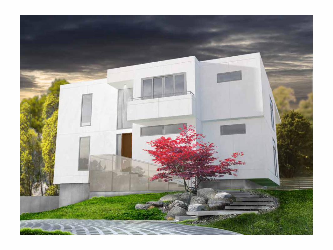
Project Scope // Project Role //WILDWOODNew construction, approx. 6000 sq ft, mod-ernist home with high-end detailing and fin-ishing. 6 bedroom and 6 1/2 bath. Currently under construction.
Worked project after SD phase and completed the CD set with advanced modeling and ren-dering to communicate with client. Additionally, designed and modeled interior spaces with product specification and material selection, as well as kitchen and bathroom layout drawings.
PARALINE


Project Name //
Architect //
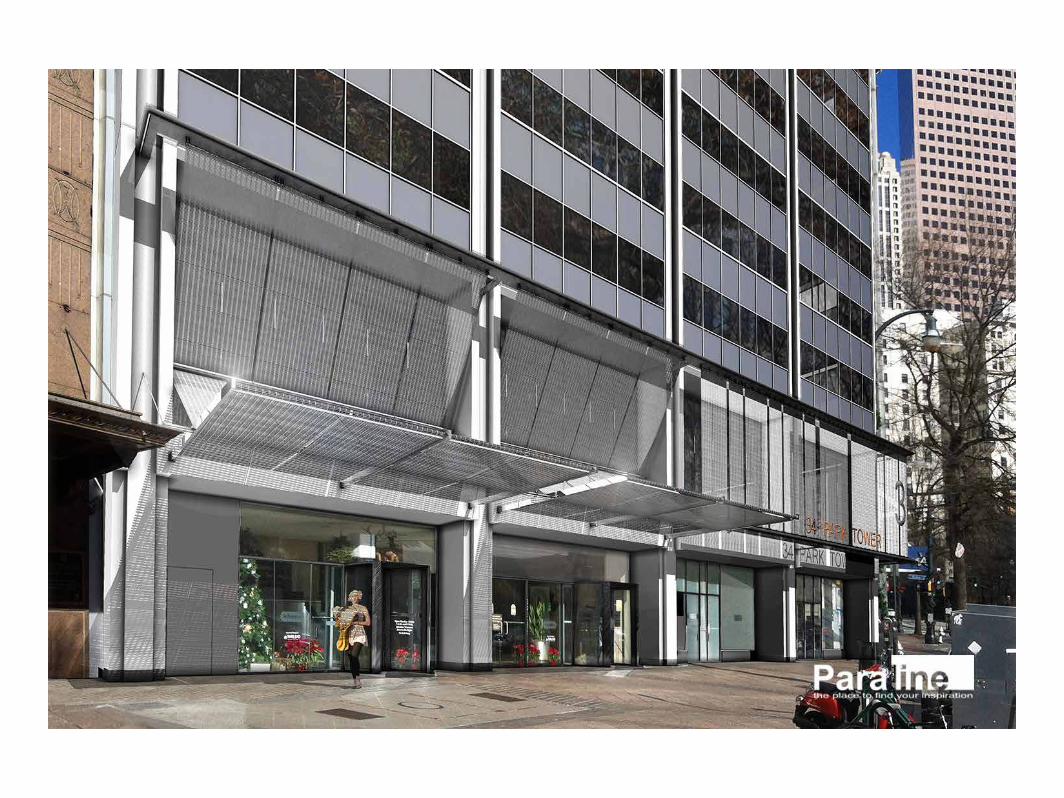
Project Scope // Project Role //34 PARK TOWERRenovation of existing street facade on histor-ic downtown highrise.
Visualization and rendering.
PARALINE

Project Name //
Architect //
Project Scope // Project Role //HIGHTOWER LIBRARYRenovation of an existing library that needed an update to retain students. Opening the southwest corner of the building to bring in light and provide a grand entry procession into the library.
Modeled existing building and SD phase conceptual designing, particularly the exterior facade.
HOUSER WALKER


Project Name //
Architect //
Project Scope // Project Role //
LEVEL 10"
LEVEL 211' - 6"
A1A210
0'-0" Main Level
9" / 12"
9" / 12"
SEE NOTE 1
A210J1
A501F5
A210L1
11' -
6"
A5
A220
6' - 8
"
9' - 8
"
BOTTOM OFTRUSS
20' - 2"
10' -
10"
3' - 0
"
LED STRIP LIGHTINGON TOP SIDE OF
HORIZONTALBRIDGING
A6A210
DUCT
ACUNIT
DUCT
BLACK FABRIC ACOUSTIC PANELS
EQ EQ
A501A1
1.75X16 LVL, ADDITIONALREQUIRED WHERE INDICATED. SEE
A102-A1
3/4" PLYWOOD FLOORING
VAPOR BARRIER
(1) 2X9 1/4 LVL
PT 2X6 FASCIA
DBL. PT 2X6 SYP
WINDOWSILLEXTENDS PAST
RAINSCREEN
A501A6
A501A4
R-30 BATT INSULATION
3/4" EXTERIOR PLYWOOD SHEATHING
2X2 PT BATTENS @ 24" O.C.
SIMPSON H2.5A @ EACH TRUSS BEARING
16 TJI210 GIRDER@ 16” O.C.
DESK COUNTERTOP
2X6 LEVEL 2 BASE PLATE
GWB CEILING
2' - 1
1"
LEVEL 10"
LEVEL 211' - 6"
10' -
0"
10' -
10"
BOTTOM OFTRUSS20' - 2"
STAT E OF GEORGI A
RE GI S T E RE D A RCHI T ECT
FRANK HOUSER
LICENSE NO. RA010
330**
SHEE
T TITL
E:
DRAW
N BY
:SC
ALE:
PROJ
ECT T
ITLE:
SEAL:
ISSUE:
PROJECT NO:
SHEET NO:
2010
Cop
yrig
ht H
ouse
r Wal
ker A
rchi
tect
ure,
LLC
All r
ight
s re
serv
ed.
J
H O U S E RW A L K E RA R C H I T E C T U R E
1819 Peachtree Rd NE, Ste102
A t l a n t a, G A 3 0 3 0 9
t. 4 0 4 . 6 3 3 . 4 2 6 4
f. 4 0 4 . 8 7 0 . 7 3 3 7
www.houserwalker.com
DATE:
REVISION DATE:
REVISION NO:
K L M N P RHGFEDCBA
9
8
7
6
5
4
3
2
1
GENERAL NOTES
SHEET SPECIFIC NOTES
RELE
ASED
FOR
CON
STRU
CTIO
N
A210
1005
07/30/14
CONSTRUCTIONDOCUMENTS
Hous
er H
ouse
Rep
lace
men
t of
Acce
ssor
y St
ruct
ure
Sect
ions
2146
McK
inle
yRd
.LL
154
of17
thDi
stric
tAt
lant
a,G
A30
318
1/4" = 1'-0"A6 E/W SECTION 1
1/4" = 1'-0"A1 N/S SECTION
1. 2X4 SYP NO. 1 O R BETTER, HORIZONTALBRIDGING @ 8" O.C. MAXIMUM,CONNECTING ALL TRUSSES. OVERLAP AMINIMUM OF 2 TRUSSES SPACES AT ALLSPLICES. ATTACH TO EACH TRUSS CROSSEDW/ 2-16D MIN. 2X12 BOARD WILL SIT ON TOP,PARALEL TO TRUSSES FOR FAN INSTALLATION.
2. TRUSS X-BRACING @ 8" O.C. (PREFERABLY INA VERTICAL PLANE, ATTACHED TO VERTICALWEB MEMBER ON EACH TRUSS CROSSED
3/4" = 1'-0"J1 WALL SECTION - W
AS IN
DICA
TED
1. DESIGN OF METAL-PLATE CONNECTED WOOD TRUSSESBY MANUFACTURER. TRUSS DESIGN, MANUFACTURING,QUALITY CONTROL AND EVALUATION SHALL CONFORMTO ANSI/TPI1-2002 "NATIONAL DESIGN STANDARD FORMETAL PLATE CONNECTED WOOD TRUSSCONSTRUCTION," BY TRUSS PLATE INSTITUTE. ALLERECTION AND PERMANENT TRUSS BRIDGING ANDBRACING SHALL BE INSTALLED AND ALL COMPONENTSPERMANENTLY FASTENED BEFORE THE APPLICATION OFSUPERIMPOSED LOADS TO THE TRUSSES. ALL TEMPORARYTRUSS BRACING SHALL BE DESIGNED BY TRUSSMANUFACTURER.
TRUSS DESIGN CRITERIA:
-LOADS: SUPERIMPOSED DEAD (NOT INCLUDING TRUSSSELF WEIGHT): 16 PSF; SUPERIMPOSED LIVE(ACCOUNTING FOR ROOF PITCH OF 9:12; REDUCIBLEPER IRC 2012 TABLE R301.6: 16 PSF.
-DEFLECTION LIMITS: L/360 (SUPERIMPOSED LIVE); L/240(SUPERIMPOSED DEAD); L/240 TOTAL.
POWER OUTLETS:
-ALL POWER OUTLETS ARE TO BE CENTERED WITHPLYWOOD PANEL
- DOUBLE OUTLETS
DIAGONAL X-BRACING @ 8" O.C.MAXIMUM, CONSISTING OF 2X4SYP NO. 1 OR BETTER. SEE NOTE 2
LATERAL 2x4 KICKERS @ 4'O.C., ALIGN AT CENTER LINE,45 DEGREE ANGLE
3/4" = 1'-0"L1 WALL SECTION - E
VIDEO PROJECTOR
(3) 1 3/4"X16" LVL
2X12 LEDGER
2X8 JOISTS
2X8 BLOCKING
GARAGE DOOR(10’-0” HEIGHTNEEDED FORFUNCTION)
2X4 X-BRACING
NEW SLAB
EXISTING SLAB
(3) 1.75X 9.25 LVL
HOUSER HOUSESmall carriage house addition to be built in the backyard of the property, involving a garage workshop and upstairs entertainment center.
Designed a number of iterations on an accessory structure to Hank Houser’s house, before settling on a tied-in structure to match the height of the existing home. From initial concept designs through permitting.
HOUSER WALKER

LEVEL 10" FLASHING
WEATHER BARRIER
2X2 VERT. BATTEN
2X2 HOR. BATTEN
3/4" PLYWOOD SHEATHING
5 1/2” R-21 BATT INSULATION
2X6 PT SYP BASE PLATE
NEW CONCRETE POUR
EXISTING CONCRETE SLAB
HOLD DOWN UNIT
1 1/8"
10 1/4"
9 3/
4"
BOTTOM OF POWER OUTLET
POWER OUTLET
2X6 PT SYP FASCIA
MONOPLANAR PITCHED TRUSS(MANUFACTURED OFF-SITE)
2X6 PT SYP
LIGHT METAL PLATE CONNECTOR
2X2 VERT. ROOF BATTEN
2X2 HOR. ROOF BATTEN
EXTERNAL 3/4” PLYWOOD
WOOD WINDOW
LEVEL 211' - 6"
2X16 LVL, ADDITIONALREQUIRED WHERE INDICATED.
SEE A102-A1
16" TJ210 GIRDER @ 16" O.C.
DBL. 2X6 SYP PLATE
3/4" PLYWOOD FLOORING
2X6 SYP PLATE
HOR. 2X2 BATTEN
WEATHER BARRIER
VERT. 2X2 BATTEN
5/8 VERT T&G CYPRESS PLANKS
5 1/2” R-21 BATT INSULATION
WEATHER BARRIER
WOODEN DOOR JAMB
WINDOW JAMB
DECK RAILING
WOOD DECKING
PLYOOD FLOORING
2
1
PW
STATE OF GEORGI A
RE GI S T E RE D A RCHI T ECT
FRANK HOUSER
LICENSE NO. RA010
330**
SHEE
T TIT
LE:
DRAW
N BY
:SC
ALE:
PROJ
ECT
TITL
E:
SEAL:
ISSUE:
PROJECT NO:
SHEET NO:
2010
Cop
yrig
ht H
ouse
r Wal
ker A
rchi
tect
ure,
LLC
All
right
s re
serv
ed.
J
H O U S E RW A L K E RA R C H I T E C T U R E
1819 Peachtree Rd NE, Ste102
A t l a n t a, G A 3 0 3 0 9
t. 4 0 4 . 6 3 3 . 4 2 6 4
f. 4 0 4 . 8 7 0 . 7 3 3 7
www.houserwalker.com
DATE:
REVISION DATE:
REVISION NO:
K L M N P RHGFEDCBA
9
8
7
6
5
4
3
2
1
GENERAL NOTES
SHEET SPECIFIC NOTES
RELE
ASED
FO
R CO
NSTR
UCTI
ON
A501
1005
07/30/14
CONSTRUCTIONDOCUMENTS
Hou
ser H
ouse
Rep
lace
men
t of
Acc
esso
ry S
truct
ure
Typi
cal D
etai
ls
2146
McK
inle
yRd
.LL
154
of17
thD
istric
tA
tlant
a,G
A30
318
3" = 1'-0"F5 RIDGE SECTION DETAIL
3" = 1'-0"A1 BASE WALL SECTION DETAIL
3" = 1'-0"A6 TOP WALL SECTION DETAIL
3" = 1'-0"A4 MID WALL SECTION DETAIL
(3) 1 3/4"X 9 1/2" LVL
RIDGE CAP
ARCHITECTURAL EXTERIOR SHEATHING
2X2 HORIZONTAL BATTEN
2X2 VERTICAL BATTEN
WEATHER BARRIER
3/4” PLYWOOD
TRUSS
2X4 HORIZONTAL BRIDGING
INTERIOR CEILING 1/2" GWB
2X4 KICKER
3" = 1'-0"F1 LEVEL 2 CORNER PLAN DETAIL
Partitions:
10 1/4”
4 1/2”
2”
DESCRIPTIONGRAPHICWIDTHTYPE MARK
_5/8” VERT T&G CYPRESS PLANKS RAIN SCREEN_HOR. 2X2 P.T. BATTENS @ 24” O.C. TYP._VERT. 2X2 P.T. BATTENS @ 24” O.C. TYP._WEATHER BARRIER_3/4” PLYWOOD SHEATHING_5 1/2” R-21 BATT INSULATION_2X6 STUDS @ 24” O.C._1/2” INTERIOR PLYWOOD SHEATHING
_1/2” PLYWOOD SHEATHING_3 1/2” R-15 BATT INSULATION_1/2” PLYWOOD SHEATHING
_1/2” GYPSUM WHITE BOARD,PAINTEDWITH 2 COATS OF SHERWIN WILLIAMSPROCLASSIC SMOOTH ENAMEL FINISHWHITE PAINT_2X4 (FLAT) FURRING ATTACHED TOSTRUCTURE
PROVIDE SIMPSONTWO-STORY STACKEDWALL CONNECTORKIT (SSW21-2KT) ATEACH LOCATION, TYP.@ 4 CORNERS
5/8 VERT T&G CYPRESS PLANKS
R-40 BATT INSULATION
6"3'
'1.
5''

Project Name //
Architect //
Project Scope // Project Role //MANATEE CLASSROOMA classroom for teaching the ecological proper-ties of Manatee island, the project has a unique shape with an upper observation deck. Main floor is situated above piers.
Came onto the project after SD phase and began to work on finalizing design in DD phase and working out the detailing in CD phase.HOUSER WALKER
LARGE CLASSROOM101
MECH ROOM106
SMALL CLASSROOM 2103
STORAGE105
01A211
01A210
02A210
SLIDE
W
A
B
C
D
E
F
G
H
J
KP
Q
R
S
T
U
V
WOOD SHELVINGABOVE
CONCRETE INSETMEDALION; OWNERFURNISHED, CONTRACTORINSTALLED
INSECT SCREEN AT SCREEN WALLAND CLERESTORY ABOVE. SEETRANSOM PLAN.
COMPRESSOR ENCLOSURE107 04
A220
04A300
A30005
A50010
A50009
A50008
05A220
10
A503
A50007
CLIMBING NET
A50005
A50002
ROOF LINE ABOVE
L
M
N
7' - 8 1/4" R.O.
8' - 7 1/
2"R.O
.
7'- 0
1/2"
R.O
.
7' - 11" R.O.
6' - 11 1/2" R.O.
9' -
8" R
.O.
01A220
2' - 7"
SEE CIVIL FORBOARDWALK
5' - 2"
4' - 0"
4' - 0"
7" MAX18 EQUAL RISERS
11" MIN
5' - 0"
4'- 0
"
7"M
AX
18EQ
UAL RI
SERS
NOTE 1
NOTE 2
NOTE 3
07
A503
Sim
NOTE 5
X-BRACING, SEE S2.2
DN
DN
02A220
03A220
12" DIA. PT WOOD POLE
A50409
NOTE 8
TI
TI
TI
TE
TE
TE
TETE
S1
TI
TI
A50403
NOTE
6
10 00 00
2' - 0"
TA
1' - 3"
1'- 3
"
1' - 5"
1'- 3
"
2' - 0"
SMALL CLASSROOM 1102
NOTE 9
AB
C
D
E
04A300
A50001
A30006
DN
CENTER OF WINDOWAND SUPPLY GRILLE, TYP
DUCT RISER BELOW FLOOR
MATERIAL KEYNOTES
GENERAL NOTES
SHEET SPECIFIC NOTES
DRAW
ING
TITLE:
SEAL
DATE :
DWG SCALE:
DRAWN BY:
SHEET No.:
CHECKED BY:
H O
U S
E R
W A
L K
E R
A R
C H
I T E
C T
U R
E
1819
PEA
CHTR
EE R
OAD
, NE
STE
102
A t
l a n
t a,
G
A 3
0 3
0 9
t. 4
0 4
. 6
3 3
. 4
2 6
4f.
4 0
4 .
8 7
0 .
7 3
3 7
ww
w.h
ouse
rwal
ker.c
om
PTA
TO THE BES
T OF TH
EARCHITEC
T'S O
REN
GINEER'S K
NOWLEDGE,
SAID P
LANS A
ND
SPEC
IFICATIONS C
OMPLY
WITH THE APPLICABLE
CODES
AND S
TANDARDS.
RELE
ASED
FO
R CO
NST
RUCT
ION
1/4" = 1'-0"
MAI
N L
EVEL
PLA
N
03/30/2015
DE
1/4" = 1'-0"01 CLASSROOM LEVEL2 41 8 NORTH 1/4" = 1'-0"02 Lookout Floor Level
A. Window rough openings are to be centered betweencolumns. Windows are to be sized equally betweenrough openings. See approximate dimensions on WindowSchedule on sheet A020.
B. Unless indicated otherwise, doors are to be centeredbetween columns.
C. See sheet A020 for typical interior wall description.D. Contractor to verify all rough opening dimensions prior to
order of scheduled windows.
1. Coordinate opening in net with slide. Net opening is tobe tight to slide perimeter to prohibit max 4" diameterfrom passing through.
2. Floor diffusers are to be located between floor joists.Provide bridge framing as necessary to support floordecking.
3. Interior wall finish to be 3/4" plywood.4. Exterior wall not to have plywood sheathing on wall.
Wood siding is to be installed as slats, for air flow. Seeassociated details.
5. Floor decking around air condensor to be spaced 1/2"apart.
6. Floor joist projections to vary from 3' to 5' beyond floordeck. Random lengths.
7. Cargo net to wrap up sides to top rope at min. 3'-6"above net floor.
8. ADA Accessible Periscope mounted to column. Ownerprovided, contractor installed.
9. Hinged floor door with closer device. Ladder to gradebelow. Owner provided, contractor installed.
10. Periscope mounted to adjacent column, provides viewthrough window at 6'-0"AFF. Owner provided,contractor installed.
NOTE 7
NOTE 4
10 00 00 SPECIALTIES


Main Floor Level10' - 0"
A50306
CONTINUOUS MISTER LINE, EVAPORATIVECOOLING SYSTEM
2 X 6 PRESSURE TREATEDPINE DECKING
2X6 T&G PINE DECKING
R30 SPRAY FOAM INSULATION
INSULATED SUPPLY DUCT SEE MECH
CONCRETE PIER SEE STRUCTURAL
SUPPLY FLOOR REGISTER
R-40
A50102
A50103
09
A500
A50105
A50101
TAPER DOWN TO EDGE
WOOD BATTEN
07 54 00.TPO
07 21 00.PIS
NOTE 2
02
A211
RAFTER TAIL VARIES FROM3' TO 5'. RANDOM, TYP.FLOOR AND ROOF JOISTS
22' - 0"MAIN ROOF LEVEL
COORDINATE WITH STRUCTURAL
CL OF COLUMNAND X-BRACEWHERE ITOCCURS. SEESTRUCTURAL
PRESSURE TREATED
VARIES
COLUMN BEYOND
06 10 00.EWS
06 15 00.PTD
10 1
/2"
07 41 13
17' - 4"
BOT. OF WINDOW HEADER
VARIES
LIGHT - WHERE IT OCCURSSEE ELECTRICAL
09
A500
A50106
Sim
2X BLOCKING BETWEEN RAFTERSRAFTER
07 62 00.MFT
NOTE 1
02
A211
23 37 14.L
06 10 00.SF
08 50 00.AL1
06 10 00.SF
F27
F3 F9
06 20 00.SWT
06 20 00.SWT
07 46 23.TGB
F27
07 62 00.FF
06 10 00.WC
A A BCD D
TYPICAL REPEATING PATTERN
KEY:
A - 7 1/8" DUTCH LAP SIDING
B - 9 1/8" DUTCH LAP SIDING
C - 5 3/8" DUTCH LAP SIDING
D - 5 1/2" STANDARD LAP SIDING
1/4"A
1/4"
EXPOSED FASTENER
BATTEN STRIP BEHIND
DB
MATERIAL KEYNOTES
GENERAL NOTES
SHEET SPECIFIC NOTES
DRAW
ING
TITLE:
SEAL
DATE :
DWG SCALE:
DRAWN BY:
SHEET No.:
CHECKED BY:
H O
U S
E R
W A
L K
E R
A R
C H
I T E
C T
U R
E
1819
PEA
CHTR
EE R
OAD
, NE
STE
102
A t l
a n
t a,
G
A 3
0 3
0 9
t. 4
0 4
. 6
3 3
. 4
2 6
4f.
4 0
4 .
8 7
0 .
7 3
3 7
ww
w.h
ouse
rwal
ker.c
om
PTA
TO THE BES
T OF TH
EARCHITEC
T'S
OR
ENGINEER'S K
NOWLEDGE,
SAID P
LANS
AND
SPEC
IFICATIONS
COMPLY
WITH THE APPLICABLE
CODES
AND S
TANDARDS.
RELE
ASED
FO
R CO
NSTR
UCTI
ON
As indicated
TYPI
CAL
WAL
L SE
CTIO
N&
ELEV
ATIO
N
03/30/2015
Author
1" = 1'-0"01 Typical Wall Section
1" = 1'-0"03 Enlarged Typical Exterior Elevation
06 10 00.EWS EXTERIOR WOOD SHEATHING06 10 00.SF STRUCTURAL FRAMING06 10 00.WC WOOD COLUMN06 15 00.PTD 2X6 PRESSURE TREATED DECKING06 20 00.SWT STAINED WOOD TRIM07 21 00.PIS BOARD INSULATION07 41 13 ROOFING07 46 23.TGB T&G BOARD SIDING07 54 00.TPO THERMOPLASTIC MEMBRANE ROOFING07 62 00.FF FLEX FLASH07 62 00.MFT FLASHING AND TRIM08 50 00.AL1 ALUM-CLAD WOOD WINDOWS
1. Window frames are to align.2. Sheathing and the weather barrier continue down past
the floor line, in order to allow the water to flow awayfrom the interior.
1 1/2" = 1'-0"02 TYPICAL SIDING PATTERN
Project Name //
Architect //
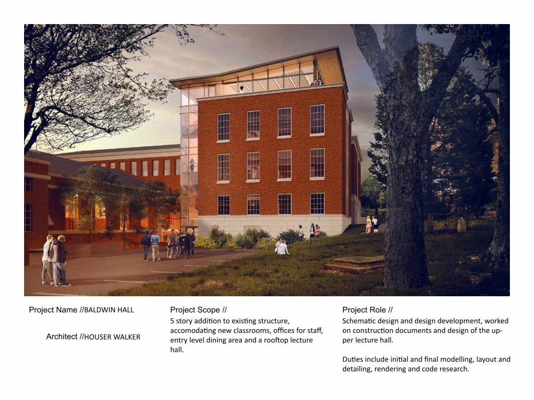
Project Scope // Project Role //BALDWIN HALL5 story addition to existing structure, accomodating new classrooms, offices for staff, entry level dining area and a rooftop lecture hall.
Schematic design and design development, worked on construction documents and design of the up-per lecture hall.
Duties include initial and final modelling, layout and detailing, rendering and code research.
HOUSER WALKER


1st Floor719' - 1"
3rd Floor745' - 1"
2nd Floor731' - 7"
4th Floor758' - 6 3/4"
Annex 2nd Floor721' - 10 3/4"
A5A210
1 4 97 12 142 17 18
E1A212
A1A210
A220K1
A220F1
103 6 15 165 8 1311
1st Floor719' - 1"
3rd Floor745' - 1"
2nd Floor731' - 7"
Annex 1st Floor711' - 7"Ground Level
709' - 11"
4th Floor758' - 6 3/4"
Annex 2nd Floor721' - 10 3/4"
A5A210
1 4 97 122
A1A210
A220A1
A220C6
A221K1
103 65 8 11
CONSULTANTS:
SHEE
T TITL
E:
DRAW
N BY
:SC
ALE:
AS
INDI
CATE
D
PROJ
ECT
TITL
E:
SEAL:
ISSUE:
PROJECT NO:
SHEET NO:
2012
Cop
yrig
ht H
ouse
r Wal
ker A
rchi
tect
ure,
LLC
All
right
s re
serv
ed.
J
H O U S E RW A L K E RA R C H I T E C T U R E
1819 PEACHTREE ROAD, NE
SUITE 102
ATLANTA, GA 30309
T. 4 0 4 . 6 3 3 . 4 2 6 4
F. 4 0 4 . 8 7 0 . 7 3 3 7
www.houserwalker.com
DATE:
CURRENT REVISION:
REVISION NO:
K L M N P RHGFEDCBA
9
8
7
6
5
4
3
2
1
CIVIL ENGINEER:
MEP ENGINEER:
STRUCTURAL ENGINEER:
MATERIAL KEYNOTES
GENERAL NOTES
SHEET SPECIFIC NOTES
c 1
/8" =
1'-0
" (w
hen
prin
ted
fulls
cale
on
22" x
34"
she
et)
A211
1429
5/19/2015
100% DESIGNDEVELOPMENT
J-24
2 Ba
ldw
in H
all E
xpan
sion
and
Ren
ovat
ion
Build
ing
Sect
ions
The
Univ
ersit
yof
Geo
rgia
Johnson, Spellman & Assoc.350 Research Ct, Ste 130Peachtree Corners, GA 30092770.447.4555
Uzun + Case1230 Peachtree St, Ste 2500Atlanta, GA 30309678.553.5200
Koons Environmental Design675 Pulaski St, Ste. 200Athens, GA 30601706.353.3838
JC
A5 N-S Section @ Connector
A1 N-S Section @ Classroom
48
216

Project Name //
Architect //
Project Scope // Project Role //EMMANUEL CHURCHRenovation and restoration of existing Church Hall.
Design conceptualizationSD documentationMaterial selection and specificationRenderingModeling
HOUSER WALKER

HOUSER WALKER ARCHITECTURE1819 Peachtree Rd NE, Suite 102, Atlanta, GA 30309 t. 4 0 4. 6 3 3. 4 2 6 4 www. houserwalker. com
8421EMMANUEL EPISCOPAL CHURCH EXISTING FLOOR PLAN CONGREGATION: 366CHOIR: 18
MARBLE ALTAR
MARBLE STEPS
MARBLE RAILS
DN
ST MATTHEWS ORGAN PIPESDN
DN
AUDIO
EXISTING WOOD SCREEN
AMBO
20 SEATS
160 SEATS
152 SEATS
18 SEATS
18 SEATS
SLOPED FLOOR1: 20
DN
DN
REAR NARTHEX
SACRISTY
NAVE SANCTUARY
CHOIR
FOUNDERS ALTAR