profibus gateway mj0177-1a-nov3006-1 - delta … · sample programs for s7-300 ... the profibus...
TRANSCRIPT

RCM-GW-PR
RoboCylinderProfibus Gateway
IAI Industrieroboter GmbH Ober der Röth 4 D-65824 Schwalbach / Taunus Phone: 06196/8895-0/Fax: 06196/8895-24 E-Mail: [email protected] Internet: http://www.eu.iai-gmbh.de
Document BA-RCM_GW_PR-EU-ERoboCylinder Profibus-GatewayVersion 1 E, November 2006
www.robocylinder.de
Operation Manual First Edition

PROFIBUS Gateway
Table of Contents 1. Overview 1
1.1 Profibus Gateway Unit................................................................................................................. 1 1.2 What Is Profibus? ........................................................................................................................ 2 1.3 Application Example of Gateway Unit ......................................................................................... 3 1.4 Features of Gateway Unit............................................................................................................ 4 1.5 Description of Model Name......................................................................................................... 6
2. Specifications and Name of Each Part ...................................................................... 7 2.1 General Specifications ................................................................................................................ 7 2.2 External Dimensions ................................................................................................................... 8 2.3 Name and Function of Each Part ................................................................................................ 9
3. Installation and Noise Elimination Measures........................................................... 15 3.1 Installation Environment. ........................................................................................................... 15 3.2 Supply Voltage .......................................................................................................................... 15 3.3 Noise Elimination Measures and Grounding............................................................................. 15 3.4 Installation ................................................................................................................................. 17
4. Wiring 18 4.1 Overall Configuration................................................................................................................. 18 4.2 I/O Signals of Gateway Unit ...................................................................................................... 20 4.3 Design of SIO Communication Network (SIO Communication)................................................ 23
4.3.1 Wiring ............................................................................................................................ 23 4.3.2 Axis Number Setting ..................................................................................................... 32
5. Slave Function ........................................................................................................ 33 5.1 Address Configuration in Each Operation Mode....................................................................... 34
5.1.1 Gateway Control Signals .............................................................................................. 34 5.1.2 Simple Direct/Position-number Specification Mode...................................................... 37 5.1.3 Numerical Specification Mode ...................................................................................... 54 5.1.4 Position-number Specification Mode ............................................................................ 60
5.2 Communication Signal Details .................................................................................................. 64 5.2.1 Overview of Communication Signal Timings ................................................................ 64 5.2.2 Communication Signals and Operation Timings........................................................... 66 5.2.3 Command Transmission ............................................................................................... 78
5.3 System Design .......................................................................................................................... 79 5.3.1 Settings for Controller Communication ......................................................................... 79 5.3.2 Settings for Profibus-DP Communication ..................................................................... 80 5.3.3 Creation of Network Configuration................................................................................ 81 5.3.4 Example of Actual Assignments ................................................................................... 86
5.4 Supported S7 Function Blocks/Functions ................................................................................. 87 5.4.1 GW_CTL_11 ................................................................................................................. 88 5.4.2 RC_NVC_11 ................................................................................................................. 89 5.4.3 RC_ESYNC_00............................................................................................................. 90 5.4.4 RC_BCMOVP_00 ......................................................................................................... 91 5.4.5 RC_READ_00............................................................................................................... 92 5.4.6 RC_WRITE_00 ............................................................................................................. 93 5.4.7 RC_PROM_00 .............................................................................................................. 94 5.4.8 RC_PMSL_00 ............................................................................................................... 94
Appendix 1. Sample Programs for S7-300.................................................................. 95 Appendix 2. Supply Format and Use Procedure of FB/FCt......................................... 98

1
PROFIBUS Gateway
1. Overview 1.1 Profibus Gateway Unit The Profibus Gateway Unit (hereinafter referred to as “Profibus Gateway” or “Gateway Unit”) is used to connect a Profibus communication protocol network on which a host programmable controller (hereinafter “PLC”) operates, to a SIO communication sub-network (Modbus communication protocol) linking ROBO Cylinder controllers. The physical standard to which the SIO communication network conforms is RS-485, and the slave addresses on this network are 1 through 16. All data exchanged between the Profibus communication network and the Modbus SIO communication network are tentatively saved in the internal memory of the Gateway Unit, and then transferred cyclically. The PLC recognizes the Gateway Unit as a remote I/O device. The Gateway Unit supports PCON-SE, ACON-SE, SCON and ERC2-SE controllers. * “Gateway” is a term used in communication networks, referring to a device that converts data to/from
different media and protocols to enable communication between networks. * Profibus protocols include Profibus-DP for factory automation (FA) and Profibus-PA for process
automation (PA). Of these two protocols, this manual covers Profibus-DP. Accordingly, “Profibus” refers to Profibus-DP throughout this manual.

2
PROFIBUS Gateway
1.2 What Is Profibus? (1) FA communication system
In FA communication, each communication specification varies depending on the communicating equipment, type of information, and purpose of communication, among others. In general, however, the FA communication system is divided into the information level, controller level and field level, as shown below.
(2) Information level
Also called “PLC upper network.” The main purpose of this network level is to transmit production information, etc., to information terminals. Ethernet is the most commonly used communication method for the information level.
(3) Controller level
Also called “Inter-PLC network.” This network level often handles real-time information of production lines. (4) Field level
Also called “PLC lower network.” This network level is mainly used to save wirings for systems controlled by a single controller. In this sense, this network is regarded as a means for “wire-saving communication.” The field level is largely divided into the device level and the sensor level.
Info
rmat
ion
leve
l C
ontro
ller l
evel
Fi
eld
leve
l
FA computer
Robot Remote I/O
Motor driver
Installed instrument
Solenoid valve
Limit switch
Sensor level
Device level
Key open network

3
PROFIBUS Gateway
(5) Profibus
Profibus is an open field network most commonly used in the world today. It was first established under DIN 19245 (German standard) in Germany in 1989, and standardized under EN 50170 (European standard) in July 1996. In January 2000, Profibus became an international standard under IEC 61158. There are two Profibus protocols designed for different purposes: Profibus-DP for factory automation (FA), and Profibus-PA for process automation. This manual covers Profibus-DP. The key features of Profibus-DP are as follows: [1] A field network realizing complete multi-vendor connectivity [2] Able to send large amounts of data at high speed.
• Up to 244 bytes of data per device • Maximum baud rate of 12 Mbps
[3] Up to 125 nodes can be connected. * For details on Profibus, refer to the operation manuals for your master unit and PLC.
Along with this manual, also read the operation manual for each controller connected. This Profibus Gateway cannot be used in any way not described as feasible in this manual. To prevent malfunction, the customer is also advised not to use settings, wirings and other uses other than those described as feasible in this manual.
1.3 Application Example of Gateway Unit The network illustrated below gives an application example of the Gateway Unit.
CPU unit
Profibus unit
(master station)
Remote I/O station Profibus Gateway
(Remote I/O station)
Remote I/O station
Remote I/O station
SIO communication network (Modbus)

4
PROFIBUS Gateway
1.4 Features of Gateway Unit With the Gateway Unit, a desired operation mode can be selected from five patterns of the numerical specification mode, one pattern of the position-number specification mode, and three patterns of the simple direct/position-number specification mode. (1) Numerical specification mode
In positioning operation in the numerical specification mode, the actuator is operated by directly specifying the position data, speed, acceleration/deceleration, and in-position band, in numerical values. In push-motion operation in the numerical specification mode, the actuator is operated by directly specifying the position data, speed, acceleration/deceleration, push band, and current-limiting value for setting push force, in numerical values. Various status signals can be input/output and current position data can be read. There are five patterns in the numerical specification mode, each accommodating a different number of connected axes. [1] Numerical specification mode, maximum 4 axes [2] Numerical specification mode, maximum 6 axes [3] Numerical specification mode, maximum 8 axes [4] Numerical specification mode, maximum 10 axes [5] Numerical specification mode, maximum 16 axes
(2) Position-number specification mode
The actuator is operated by specifying position numbers. The position data, speed, acceleration/deceleration, etc., must be entered beforehand in the position data table for each axis. Various status signals can be input/output and current position data can be read. Up to 16 axes can be connected in the position-number specification mode
(3) Simple direct/position-number specification mode
In this mode, the actuator can be moved via combination of position number specification and direct specification (position data is specified in numerical values, while other movement parameters are specified by position numbers). Axis numbers must be assigned from position-number specification axes first, followed by simple direct specification axes. Depending on the size of the assigned area, this mode is available in the large pattern (160 bytes for input and output, respectively), middle pattern (128 bytes for input and output, respectively), and small pattern (64 bytes for input and output, respectively). Up to 16 axes can be connected as a total of both types of axes.
This manual only describes the controls feasible using the Gateway Unit. In the event of any conflict between this manual and the operation manual for the controller, the content of this manual will prevail. Refer to the operation manual for each controller for any function, parameter setting, alarm detail or any other information not described in this manual.
5
PROFIBUS Gateway
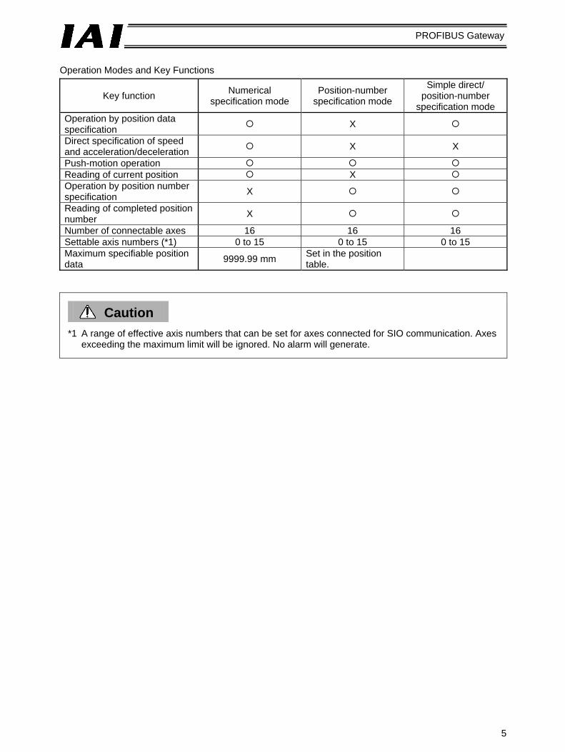
Operation Modes and Key Functions
Key function Numerical specification mode
Position-number specification mode
Simple direct/ position-number
specification mode Operation by position data specification X
Direct specification of speed and acceleration/deceleration X X
Push-motion operation Reading of current position X Operation by position number specification X
Reading of completed position number X
Number of connectable axes 16 16 16 Settable axis numbers (*1) 0 to 15 0 to 15 0 to 15 Maximum specifiable position data 9999.99 mm Set in the position
table.
Caution
*1 A range of effective axis numbers that can be set for axes connected for SIO communication. Axes exceeding the maximum limit will be ignored. No alarm will generate.

6
PROFIBUS Gateway
1.5 Description of Model Name
Base model Profibus specification
Gateway Unit

7
PROFIBUS Gateway
2. Specifications and Name of Each Part 2.1 General Specifications
Item Specification Power supply 24 VDC ± 10% Current consumption 300 mA max.
Group 2 only server
Communication standard
Insulated node of network powered operation type Bit strobe Polling
Communication specification Master-slave connection
Cyclic Baud rate 500 k / 250 k / 125 kbps (Changed by DIP switches)
Baud rate Maximum network length
Maximum branch length
Total branch length
500 kbps 100 m 39 m 250 kbps 250 m 78 m 125 kbps 500 m
6 m 156 m
Communication cable length (*1)
Note) When a large cable is used.
Pro
fibus
spe
cific
atio
ns
Transmission path configuration IAI’s original multi-drop differential communication Communication method Half-duplex Synchronization method Asynchronous Transmission path type EIA RS485, 2-wire type Baud rate 230.4 kbps Error control method No parity bit, CRC (*2) Communication cable length Total cable length: 100 m max. Connected units 16 axes max.
SIO
com
mun
icat
ion
spec
ifica
tions
Communication cable Double shielded twisted-pair cable (Recommended cable: HK-SB/20276 X L, 2P X AWG22 by Taiyo Electric Wire & Cable)
Ambient operating temperature 0 to 40° C Ambient operating humidity 85% RH or below (non-condensing) Operating ambience Free from corrosive or flammable gases, oil mist or powder dust Storage temperature -10 to 65° C Storage humidity 90% RH or below (non-condensing) E
nviro
nmen
t
Vibration durability 4.9 m/s2 (0.5 G) Protection class IP20 Weight 480 g or below
*1 Refer to the operation manuals for your master unit and PLC in the case of T-branch communication. *2 CRC: Cyclic Redundancy Check
A data error detection method commonly used in synchronous transmission.

8
PROFIBUS Gateway
2.2 External Dimensions
(Inst
alle
d di
men
sion
)
9
PROFIBUS Gateway
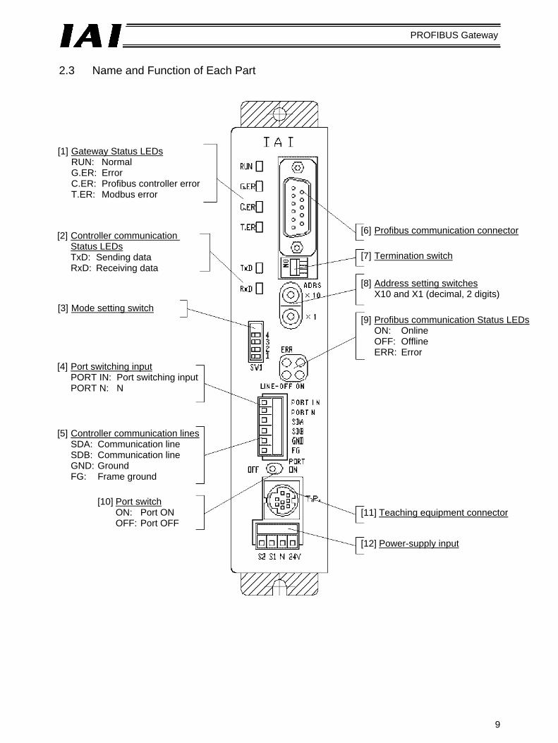
2.3 Name and Function of Each Part
[1] Gateway Status LEDs RUN: Normal G.ER: Error C.ER: Profibus controller error T.ER: Modbus error
[2] Controller communication Status LEDs TxD: Sending data RxD: Receiving data
[3] Mode setting switch
[4] Port switching input PORT IN: Port switching input PORT N: N
[5] Controller communication lines SDA: Communication line SDB: Communication line GND: Ground FG: Frame ground
[10] Port switch ON: Port ON OFF: Port OFF
[6] Profibus communication connector
[7] Termination switch
[8] Address setting switches X10 and X1 (decimal, 2 digits)
[9] Profibus communication Status LEDs ON: Online OFF: Offline ERR: Error
[11] Teaching equipment connector
[12] Power-supply input

10
PROFIBUS Gateway
[1] Gateway status LEDs
Indicated status Description Steady green The Gateway CPU is operating. RUN
Unlit CPU operation is stopped. If this LED does not come on after turning on the power, the Gateway is experiencing a CPU error.
Steady red The Gateway is experiencing a CPU error or major shutdown failure. G.ER Unlit Normal state.
Steady red The Profibus module is experiencing an error or the Gateway CPU cannot recognize the Profibus connection. (Check the Profibus communication status in [9].) Even if this LED is lit, the teaching pendant or PC software can still be connected as long as the RUN LED is lit.
Blinking red While the port is ON, this LED blinks at 1-second intervals.
C.ER
Unlit Normal state. Steady red A communication error occurred between the Profibus Gateway and the
controller. (No response, overrun, framing error or CRC(*) error)
T.ER
Unlit Normal state. * CRC: Cyclic Redundancy Check
A data error detection method commonly used in synchronous transmission. [2] SIO communication status LEDs
These LEDs are used to check the communication status between the Profibus Gateway and the controller. Each LED blinks when the host PLC and controller are not communicating via the Profibus Gateway, or when the controller is communicating with the teaching pendant or PC software connected via the Profibus Gateway.
Indicated status Description
Blinking green Sending data (Profibus Gateway → Controller) TxD Unlit Not sending data (Profibus Gateway → Controller)
Blinking green Receiving data (Controller → Profibus Gateway) RxD Unlit Not receiving data (Controller → Profibus Gateway)

11
PROFIBUS Gateway
[3] Mode setting switch
This switch is used to set the operation mode of the Profibus Gateway. Operate the switch after turning off the Profibus Gateway power.
: ON X: OFF
SW1 I/O bytes No. 4 3 2 1 Description Output Input 1 X X X X Numerical specification mode, maximum 4 axes 52 28 2 X X X Numerical specification mode, maximum 6 axes 76 40 3 X X X Numerical specification mode, maximum 8 axes 100 52 4 X Numerical specification mode, maximum 10 axes 124 64 5 X X Numerical specification mode, maximum 16 axes 196 100 6 X X X Position-number specification mode,
maximum 16 axes 48 48
7 X X X Simple direct/position-number specification mode, Large
160 160
8 X X Simple direct/position-number specification mode, Middle
128 128
9 X X Simple direct/position-number specification mode, Small
64 64
[4] External port switching input
The ON/OFF status of the teaching pendant/PC connector port can be switched using external signals (no-voltage contact type). The connector port is enabled when the port switch [10] on the Profibus Gateway is OFF. When the input signal is ON, the port is also ON. PORT IN: Port control input PORT N: Port control input, N side Use an input current of 7 mA and external signals of no-voltage contact type
[5] Controller communication lines
This terminal is used to connect the communication lines to the SIO communication connector. Refer to 4.2, “I/O Signals of Gateway Unit” for details.
[6] Profibus communication connector
This connector is used to connect the Profibus communication lines.
Connector assignments (D-sub, 9-pin) Pin Signal Housing Shield 1 NC 2 NC 3 B-Line 4 RTS* 5 GND BUS** 6 +5V BUS** 7 NC 8 A-Line 9 NC

12
PROFIBUS Gateway
[7] Termination switch
A terminal resistor must be provided at the end of the Profibus trunk line to prevent bus reflection. Set the termination switch to the ON position when the Profibus Gateway is the terminal module. However, the switch should be set to the OFF position if an external termination connector is used. Set the switch to the OFF position if the Gateway is not the terminal module.
[8] Address setting switches
The two rotary switches are used to set a decimal node address in a range of 1 to 99. X10: Set the 10’s digit of the two-digit decimal address. X1: Set the 1’s digit of the two-digit decimal address.
13
PROFIBUS Gateway
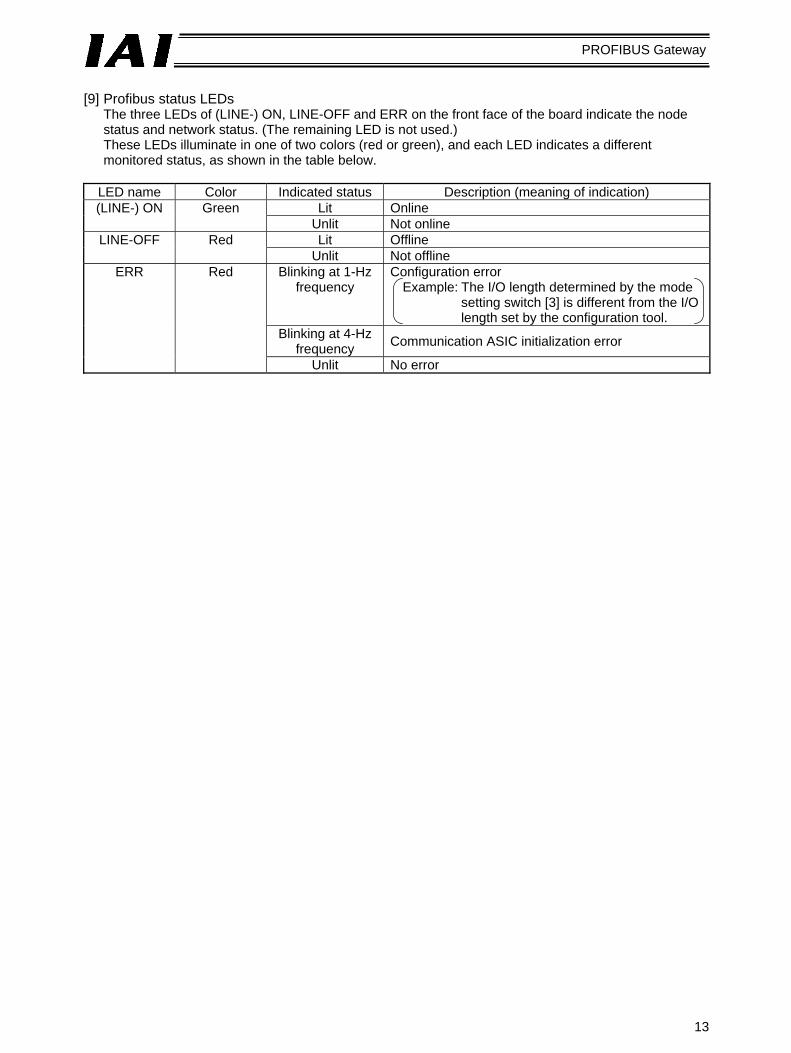
[9] Profibus status LEDs
The three LEDs of (LINE-) ON, LINE-OFF and ERR on the front face of the board indicate the node status and network status. (The remaining LED is not used.) These LEDs illuminate in one of two colors (red or green), and each LED indicates a different monitored status, as shown in the table below.
LED name Color Indicated status Description (meaning of indication)
Lit Online (LINE-) ON Green Unlit Not online Lit Offline LINE-OFF Red
Unlit Not offline Blinking at 1-Hz
frequency Configuration error
Example: The I/O length determined by the mode setting switch [3] is different from the I/O length set by the configuration tool.
Blinking at 4-Hz frequency Communication ASIC initialization error
ERR Red
Unlit No error

14
PROFIBUS Gateway
[10] Port switch
This switch is used to enable the teaching pendant/PC connector (TP) (PORT ON = Start communication). Set this switch to the OFF position when connecting/removing the communication cable connector for teaching pendant or PC software. To use the teaching pendant or PC software, plug in the connector first, and then set the switch to the OFF position. (Also check the signal status of the port switching input [4].) Port switch ON: Power (24 VDC) is supplied to the teaching pendant. The emergency stop circuit of
the teaching pendant is enabled. Port switch OFF: Power (24 VDC) to the teaching pendant is cut off. The emergency stop circuit of
the teaching pendant is disabled. [11] Teaching pendant/PC connector
This connector is used to connect the communication cable connector for teaching pendant or PC software.
[12] Power-supply input
This connector is used to connect the Profibus Gateway power (24 VDC). Refer to “I/O Signals of Gateway Unit” in Chapter 4.

15
PROFIBUS Gateway
3. Installation and Noise Elimination Measures
Exercise due caution regarding the installation environment. 3.1 Installation Environment.
a. The Gateway Unit is not dustproof or waterproof (oilproof). Accordingly, avoid using the Gateway Unit in a dusty place or place where the unit may come in contact with oil mist or splashed cutting fluid.
b. Prevent the Gateway Unit from receiving direct sunlight or irradiated heat from large heat sources such as heat treatment ovens.
c. Use the Gateway Unit in an environment of 0 to 40° C in ambient temperature and 85% or below in humidity (non-condensing) and free from corrosive or flammable gases.
d. Use the Gateway Unit in an environment where the unit will not receive external vibration or shock.
e. Prevent electrical noise from entering the Gateway Unit or its cables. 3.2 Supply Voltage
24 VDC ± 10% / Current consumption: 300 mA max. 3.3 Noise Elimination Measures and Grounding
a. Installing the Gateway Unit
Connect the Gateway Unit by directly securing it onto a metal enclosure using screws.
Use as thick a cable as possible and connect it over the shortest possible distance.
Metal enclosure
* Provide class D (3) grounding for the enclosure.

16
PROFIBUS Gateway
b. Notes on wiring method
Separate the communication lines of the Gateway Unit and Profibus module from lines carrying large current such as power circuits. (Do not bundle them together or place them in the same cable duct.)
c. Noise sources and elimination of noise
There are many noise sources, but the ones you should pay most attention to when building your system are solenoid valves, magnet switches and relays. Noise from these sources can be eliminated using the following measures.
[1] AC solenoid valves, magnet switches, relays
Measure --- Install a surge killer in parallel with the coil.
[2] DC solenoid valves, magnet switches, relays
Measure --- Install a diode in parallel with the coil. Determine an appropriate diode capacity in accordance with the load capacity.
← Point Install the surge killer in a location as close as possible to each coil. If the surge killer is installed on a terminal block or away from the coil, its noise elimination effect will decrease.
In a DC system, connecting the diode in reverse polarities may damage the diode, internal controller parts, and DC power supply. Exercise due caution.
Anode Cathode

17
PROFIBUS Gateway
3.4 Installation Examine appropriate settings for the control box size, installation position of the Gateway Unit and cooling method of the control box, so that the temperature around the Gateway Unit will remain at or below 40° C. Install the Gateway Unit vertically on a wall, as shown below, and provide a minimum clearance of 50 mm above and below the unit, with a minimum clearance of 100 mm provided on all sides for wiring access. If multiple Gateway Units are installed side by side, provide a sufficient space between the adjacent units so that any unit can be installed and removed easily. If heat or noise is of concern, also provide appropriate measures.

18
PROFIBUS Gateway
4. Wiring 4.1 Overall Configuration The following is an example of Profibus system configuration using the Gateway Unit.
SIO
com
mun
icat
ion
netw
ork
Term
inal
resi
stor
4-w
ay ju
nctio
n
Hos
t sys
tem
(PLC
mas
ter)
Gat
eway
U
nit
Teac
hing
pen
dant
24-V
po
wer
su
pply

19
PROFIBUS Gateway
The SIO link may be implemented as a multi-drop link using terminal blocks, as shown below.
Gateway Unit
Terminal block
Terminal resistor

20
PROFIBUS Gateway
4.2 I/O Signals of Gateway Unit (1) Connection diagram
Gateway Unit
Profibus communication cable
Teaching pendant Teaching pendant/ PC connector
Emergency stop
External emergency stop
Controller’s EMG or emergency stop relay
Gateway power supply24 VDC ±10%, 300 mA max.
External port switching input (provided by the customer)
(Load: 24 VDC, 7 mA)
Port switch
SIO communication cable

21
PROFIBUS Gateway
(2) Port control and emergency stop signal output
The teaching pendant/PC connector port can be operated by external signals, other than by ON/OFF switching of the port switch on the Gateway Unit. While the port is ON, the Gateway Unit outputs contact signals of the emergency stop pushbutton switch on the teaching pendant. Therefore, you can design an emergency stop circuit or other protective circuit for the entire system by incorporating these signals.
External port
switching input Port switch Teaching-pendant emergency
stop signal output Teaching pendant/PC
connector port OFF OFF Disabled (S1 and S2 shorted) Disabled ON OFF OFF ON ON ON
EnabledS1, S2 = Teaching-pendant emergency stop contacts
Enabled

PROFIBUS Gateway
22
S
ymbo
l D
escr
iptio
n S
peci
ficat
ion
Con
nect
or a
nd a
pplic
able
wire
24 V
P
ositi
ve s
ide
of th
e 24
-VD
C
Gat
eway
pow
er s
uppl
y 24
VD
C ±
10%
0.
8 to
1.3
mm
2
N
Neg
ativ
e si
de o
f the
24-
VD
C
Gat
eway
pow
er s
uppl
y Po
wer
con
sum
ptio
n: 3
00 m
A m
ax.
AWG
18
to 1
6
S1
Allo
wab
le lo
ad v
olta
ge: 3
0 V
DC
0.
08 to
1.5
mm
2
Power-supply input connector
S2
Teac
hing
-pen
dant
em
erge
ncy
stop
sig
nal o
utpu
t A
llow
able
load
cur
rent
: 1 A
A
WG
28
to 1
6
The
conn
ectio
n pl
ug is
a
stan
dard
acc
esso
ry.
M
C1.
5/4-
ST-
3 8
1 (P
hoen
ix C
onta
ct)
PO
RT
IN
PO
RT
N
Ext
erna
l por
t sw
itchi
ng in
put
No-
volta
ge (d
ry) c
onta
ct in
put
Load
: 24
VD
C, 7
mA
0.
08 to
1.5
mm
2 A
WG
28
to 1
6 S
DA
S
IO c
omm
unic
atio
n lin
e A
S
DB
S
IO c
omm
unic
atio
n lin
e B
G
ND
G
roun
d
Alig
n th
e po
tent
ial l
evel
of t
he
conn
ecte
d co
ntro
ller o
r ER
C
actu
ator
with
the
pote
ntia
l lev
el o
f th
e G
ND
(gro
und)
.
SIO communication connector
FG
Fram
e gr
ound
In
tern
ally
con
nect
ed to
the
fram
e.
Dou
ble
shie
lded
tw
iste
d-pa
ir ca
ble
(AW
G22
)
Rec
omm
ende
d ca
ble:
H
K-S
B/2
0276
X L
2P
X A
WG
22 b
y Ta
iyo
Ele
ctric
Wire
& C
able
The
conn
ectio
n pl
ug is
a
stan
dard
acc
esso
ry.
M
C1.
5/6-
ST-
3 5
(P
hoen
ix C
onta
ct)
The
Gat
eway
Uni
t has
a
built
-in te
rmin
al re
sist
or, s
o co
nnec
t the
term
inal
re
sist
or a
t the
end
of t
he
SIO
com
mun
icat
ion
line.
Profibus communication
connector
Th
e co
nnec
tion
plug
is a
st
anda
rd a
cces
sory
. A
term
inal
resi
stor
mus
t be
conn
ecte
d at
eac
h en
d of
th
e P
rofib
us tr
unk.
Che
ck
the
oper
atio
n m
anua
l for
th
e m
aste
r (P
LC).
(3) I/O signal specifications and wires

23
PROFIBUS Gateway
4.3 Design of SIO Communication Network (SIO Communication) 4.3.1 Wiring (1) Basics
Item Description
Number of connected units 16 axes max. (The specific number varies depending on the operation mode. Refer to 1.4, “Features of Gateway Unit.”)
Communication cable length Total cable length: 100 m max.
Communication cable Double shielded twisted-pair cable (AWG22) Recommended cable: HK-SB/20276 X L 2P X AWG22
by Taiyo Electric Wire & Cable Terminal resistor 220 Ω 1/4 W
Caution
1. Connect the communication path to a bus and always connect a terminal resistor at the end. A terminal resistor is not needed on the Gateway Unit end, as the unit has a built-in terminal resistor.
2. The customer must provide the communication cable. If the recommended cable is not used, make sure the size of the cable to be used is AWG22.
(2) Linking PCON-SE/ACON-SE controllers
Gateway Unit (Built-in terminal resistor)
SIO communication trunk
e-CON connector (4-1473562-4 by AMP, green) e-CON connector (3-1473562-4 by AMP, orange) Junction (5-1473574-4 by AMP) Recommended cable: SB/20276 X L 2P X AWG22
Axis 1 Axis 2 Axis n
Controller link cable
Terminal resistor

24
PROFIBUS Gateway
a. Detail connection diagram
Details of SIO link connection are illustrated below. Controller link cables are available as options, but the customer must provide the communication trunk.
b. Producing a communication trunk
[1] Strip the sheath of a double shielded twisted-pair cable by approx. 15 to 20 mm.
[2] Place a cable protection tube over the cable. [3] Insert three un-stripped core wires into the cable insertion
holes in the connector. [4] With the cable inserted in the press-fit cable housing,
apply pressure from above to pressure-weld the core wires.
[5] Heat-treat the cable protection tube.
e-CON connector pin numbers
Always insert a terminal resistor (220 Ω, 1/4 W) at the end of the communication trunk (between pins 1 and 2 of the e-CON connector).
Gateway Unit Double shielded twisted-pair cable Recommended cable: HK-SB/20276 X L 2P X AWG22 by Taiyo Electric Wire & Cable
SIO communication trunk
4-way junction (5-1473574-4 by AMP)
e-CON connector (4-1473562-4 by AMP)Housing color: Green
Controller link cable
Yellow
Orange
Blue
Yellow
Orange
Blue
e-CON connector (3-1473562-4 by AMP)Housing color: Orange
Unit 1 Unit 2
e-CON connector Apply pressure.
Locking tab
Cable tube
Double shielded twisted-pair shielded
Locking tab

25
PROFIBUS Gateway
26
PROFIBUS Gateway
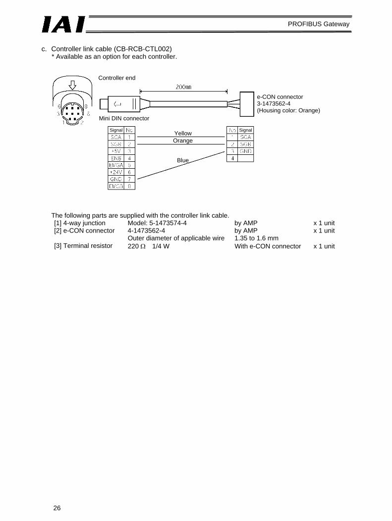
c. Controller link cable (CB-RCB-CTL002)
* Available as an option for each controller.
The following parts are supplied with the controller link cable. [1] 4-way junction Model: 5-1473574-4 by AMP x 1 unit [2] e-CON connector 4-1473562-4 by AMP x 1 unit Outer diameter of applicable wire 1.35 to 1.6 mm [3] Terminal resistor 220 Ω 1/4 W With e-CON connector x 1 unit
Controller end
Mini DIN connector
e-CON connector 3-1473562-4 (Housing color: Orange)
Signal YellowOrange
Blue
Signal

27
PROFIBUS Gateway
(3) Linking ERC2-SE controllers
* The customer must provide the terminal resistor and relay terminal blocks.
Gateway Unit (Built-in terminal resistor)
Relay terminal block (*) Axis 1
Axis 2
Axis n
Terminal resistor (*)
Recommended cable: HK-SB/20276 X L 2P X AWG22 by Taiyo Electric Wire & Cable

28
PROFIBUS Gateway
Detail connection diagram (4) Mixing PCON-SE/ACON-SEC/ERC2-SE connectors
Follow the basic configurations in (2) and (3) above. Wire the controllers in accordance with the method explained in 4.1, “Overall Configuration.”
Gateway Unit Double shielded twisted-pair cable Recommended cable: HK-SB/20276 X L 2P X AWG22 by Taiyo Electric Wire & Cable
Axis 1
SGA (red)
SGB (black)
GND pink
Orange(red 1) Orange(black 1)
(black 1)
Connect to the negative side of the 24-V power supply fro ERC2-SE.
Axis 2
SGA (red)
SGB (black)
GND pink
Orange(red 1) Orange(black 1)
(black 1)
Connect to the negative side of the 24-V power supply fro ERC2-SE.
To axis 3

29
PROFIBUS Gateway
(5) Wiring the emergency stop (EMG) circuit When designing an emergency stop circuit that incorporates the emergency stop switch on the teaching pendant connected to the Gateway Unit, emergency stop signals output from the “S1” and “S2” terminals of the Gateway Unit can be used. This way, all connected ROBO Cylinder controllers can be stopped instantly in case of emergency by operating the emergency stop switch on the teaching pendant connected to the Gateway Unit.
Caution
1. For details on the emergency stop processing of ROBO Cylinders, refer to the operation manual for your PCON-SE, ACON-SE, SCON or ERC-2 SE controller.

30
PROFIBUS Gateway
[1] Example of cutting off drive signals
Caution: The input current specification for the PCON-SE’s EMG terminal is 5 mA. When connecting the EMG relay R contacts to the EMG terminals of multiple controllers, check the current capacity of the relay contacts.
Teaching pendant Gateway Unit
EMG pushbutton
TP connector
EMG pushbutton
EMG reset
switch
Gatewaypower supply
Port switch
SIO communication
SIO connector PCON-SE controller
24-VDC input power supply
(2 A max. per unit)
Power-supply terminal block
Connection detection signal (H)
SIO connector connection detection
circuit
EMG signal detection (H)
Motor drive power
Control power
Time cons-tant
Drive stop signal (L) Motor
drive circuit
Power-supply terminal block (unit 2)
Power-supply terminal block (unit 3)

31
PROFIBUS Gateway
[2] Example of cutting off motor drive power
Teaching pendant Gateway Unit
EMG pushbutton
TP connector
EMG pushbutton
EMG reset
switch
Gatewaypower supply
Port switch
SIO communication
SIO connector PCON-SE controller
24-VDC input power supply
(2 A max. per unit)
Power-supply terminal block
Connection detection signal (H)
SIO connector connection detection
circuit
EMG signal detection (H)
Motor drive power
Control power
Time cons-tant
Drive stop signal (L) Motor
drive circuit
Power-supply terminal block (unit 2)
Power-supply terminal block (unit 3)

32
PROFIBUS Gateway
4.3.2 Axis Number Setting The following explanation applies to PCON-SE, ACON-SE and ERC2-SE controllers.
Set an axis number as a SIO-linked slave station number. The axis number of axis 1 is “0,” while that of axis 16 is “F.” Set an appropriate axis number using a hexadecimal value between 0 and F. Axis numbers can be set on the teaching pendant or in the PC software.
Operation in the PC software [1] Open the main window → [2] Click Settings (S) → [3] Bring the cursor to Controller Settings (C) → [4] Click Assign Axis Number (N) → [5] Enter a number in the axis number table.
Operation on the teaching pendant RCM-T [1] Open the User Adjustment window → [2] Bring the cursor to Assigned No. using the key → [3] Enter an axis number, and press Enter → [4] Enter “2” under Adjustment No., and press Enter.
Operation on the simple teaching pendant RCM-E [1] Open the User Adjustment window [2] Press Enter to open the Assigned No. window → [3] Enter an axis number, and press Enter → [4] Enter “2” under Adjustment No., and press Enter.
For details on each setting method, refer to the operation manual for your teaching pendant or PC software.
Caution
1. Each axis number must be unique. 2. Before setting an axis number for a given axis, disconnect the link cable of the applicable axis. 3. Connect a terminal resistor between SGA and SGB on the terminal module.

33
PROFIBUS Gateway
5. Slave Function All data exchanged between the master station and the controller are tentatively stored in the internal memory of the Gateway Unit, and then transmitted cyclically. Accordingly, the PLC program recognizes these data as remote Profibus I/Os. Up to 16 ROBO Cylinder controllers can be connected to the Gateway Unit, with the connected controllers assigned an axis number of 0 to 15, respectively. The Gateway Unit simultaneously sends and receives data to/from the master station for all ROBO Cylinder controllers connected via SIO link.

34
PROFIBUS Gateway
5.1 Address Configuration in Each Operation Mode As explained in 1.4, “Features of Gateway Unit,” the connected controller(s) can be operated in three main modes. The slave address configuration is different in each of these modes. 5.1.1 Gateway Control Signals As for the address configuration in each mode, the initial fixed area provides signals used to control the Gateway Unit. Both input and output signals consist of four bytes each. Gateway control signals are used to control the ON/OFF status of SIO link communication and monitor the SIO link communication status and Gateway Unit status. PLC output PLC input * Byte addresses are relative address recognized with respect to the head byte address of the Gateway.
Gateway control signal 0
Gateway control signal 1
Byte address
Gateway status signal 0
Gateway status signal 1

35
PROFIBUS Gateway
I/O Signal List
Signal type Byte Bit Signal name Description
7 MON
SIO link communication will start when this signal is turned ON, and stop when it is turned OFF. Do not turn the MON signal ON when CFG15 to 0 (linked axis connection) are all OFF. Also, do not turn all of CFG15 to 0 OFF when the MON signal is ON. If CFG15 to 0 are all turned OFF and the MON signal turned ON, the Gateway Unit will generate a SIO link error and the LED (T.ER) on the front face of the unit will illuminate.
+0
6-0 --- These bits cannot be used. Always set them to OFF (0).
7 NPS4
6 NPS3
5 NPS2
4 NPS1
3 NPS0
These bits are used in the simple direct/position-number specification mode. In any other mode, always set them to OFF (0). Set the number of axes (0 to 16) used in the position-number specification mode using a five-bit binary value.
2 PPS2
1 PPS1
Control signal 0
1
0 PPS0
These bits are used in the simple direct/position-number specification mode. In any other mode, always set them to OFF (0). Set the I/O pattern (pattern 0 to 5) for axes specified in the position-number specification mode, using a three-bit binary value.
7 CFG15 Link ON Axis No. 156 CFG14 145 CFG13 134 CFG12 123 CFG11 112 CFG10 101 CFG9 9
2
0 CFG8 87 CFG7 76 CFG6 65 CFG5 54 CFG4 43 CFG3 32 CFG2 21 CFG1 1
PLC
out
put
Control signal 1
(Connected axis number specification)
3
0 CFG0 0
Specify the axis number corresponding to each axis to be linked. The axis will be connected when the signal is turned ON (1), and disconnected when it is turned OFF (0). ON/OFF switching is permitted even when the MON signal is ON. (Notes)
Do not turn ON the axis number signal corresponding to any axis not physically connected.
Do not turn ON any axis number signal other than the specifiable number selected by the mode setting switch.
If either of the above conditions is breached, a SIO link error will occur.

36
PROFIBUS Gateway
Signal type Byte Bit Signal name Description
7 RUN
Gateway Unit normal output
This signal remains ON while the Gateway Unit is operating normally. The signal is synchronized with the illumination of the LED (RUN) on the front face of the unit.
6 G.ER
Gateway Unit error detection output
This signal turns ON when a major shutdown failure has been detected. The signal is synchronized with the illumination of the LED (G.ER) on the front face of the unit.
5 T.ER
SIO-link communication error detection output
This signal turns ON when a SIO link communication error has been detected. The signal is synchronized with the illumination of the LED (T.ER) on the front face of the unit.
4 TPC Port switch ON output The status of the port switch on the front
face of the unit is output. This signal is ON while the port switch is ON.
3 MOD4 Mode setting switch 4 ON output
2 MOD3 Mode setting switch 3 ON output
1 MOD2 Mode setting switch 2 ON output
+0
0 MOD1 Mode setting switch 1 ON output
The setting status of each pin of the mode setting switch is output.
7 Major V.4 6 Major V.2 5 Major V.1
The major version number is output as a three-bit binary value.
4 Minor V.163 Minor V.8 2 Minor V.4 1 Minor V.2
Control signal 0
1
0 Minor V.1
The major version number is output as a five-bit binary value.
The Gateway version information is output. You may need to check this information in certain situations, such as when the Gateway encountered a problem. Provide the necessary wiring so that these signals can be read by the PLC. Example) If the version is 1.03, the major
version number is “1” (data: 001), while the minor version number is “3” (data: 00011).
7 LNK15 Linked Axis No. 156 LNK14 145 LNK13 134 LNK12 123 LNK11 112 LNK10 101 LNK9 9
2
0 LNK8 87 LNK7 76 LNK6 65 LNK5 54 LNK4 43 LNK3 32 LNK2 21 LNK1 1
PLC
inpu
t
Status signal 1
3
0 LNK0 0
Link connection of an axis selected for link connection by any one of CFG15 to 0 will become enabled when the MON signal is turned ON. The signal corresponding to each axis whose link connection is enabled turns ON.

37
PROFIBUS Gateway
5.1.2 Simple Direct/Position-number Specification Mode This operation mode combines the mode in which the actuator is operated by specifying position numbers, and the simple direct specification mode in which the target position data is specified numerically while other movement data is specified by position numbers. The key functions that can be controlled in this mode are summarized in the table below.
Key function Position-number
specification axis Simple direct
specification axis Remarks
Home return operation Positioning operation ∆ Position table
/direct position command Speed and acceleration/deceleration setting
∆ ∆ Position table
Pitch (incremental) feed ∆ X Position table Push-motion operation ∆ ∆ Position table Speed change during movement ∆ ∆ Operation with acceleration and deceleration set differently
∆ ∆ Position table
Pause Zone signal output X Each zone is set by
parameters. PIO pattern selection X X
38
PROFIBUS Gateway
1. Overall Address Configuration
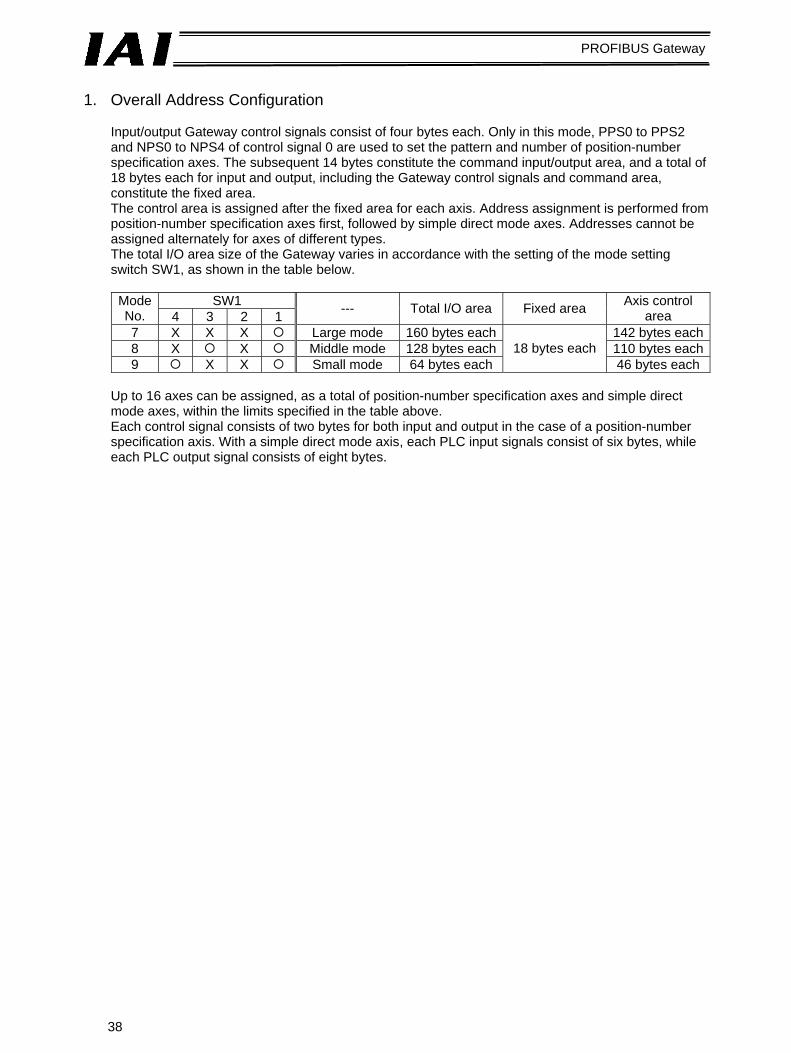
Input/output Gateway control signals consist of four bytes each. Only in this mode, PPS0 to PPS2 and NPS0 to NPS4 of control signal 0 are used to set the pattern and number of position-number specification axes. The subsequent 14 bytes constitute the command input/output area, and a total of 18 bytes each for input and output, including the Gateway control signals and command area, constitute the fixed area. The control area is assigned after the fixed area for each axis. Address assignment is performed from position-number specification axes first, followed by simple direct mode axes. Addresses cannot be assigned alternately for axes of different types. The total I/O area size of the Gateway varies in accordance with the setting of the mode setting switch SW1, as shown in the table below.
SW1 Mode
No. 4 3 2 1 --- Total I/O area Fixed area Axis control area
7 X X X Large mode 160 bytes each 142 bytes each8 X X Middle mode 128 bytes each 110 bytes each9 X X Small mode 64 bytes each
18 bytes each 46 bytes each
Up to 16 axes can be assigned, as a total of position-number specification axes and simple direct mode axes, within the limits specified in the table above. Each control signal consists of two bytes for both input and output in the case of a position-number specification axis. With a simple direct mode axis, each PLC input signals consist of six bytes, while each PLC output signal consists of eight bytes.

39
PROFIBUS Gateway
* Byte addresses are relative addresses recognized with respect to the Gateway head address.
Output from PLC ⇒ Gateway Unit ⇒ Input to each axis
Output from each axis ⇒ Gateway Unit ⇒ Input to PLC
Byte address Upper byte Lower byte Upper byte Lower byte
Gateway control signal 0 Gateway control signal 1
Request command Data 0 Data 1 Data 2 Data 3 Data 4 Data 5
(Addresses assigned to each axis follow.)
2 bytes Position-number specification axis control signal
Simple direct specification axis control signal 8 bytes
Gateway status signal 0 Gateway status signal 1
Response command Data 0 Data 1 Data 2 Data 3 Data 4 Data 5
(Addresses assigned to each axis follow.)
Position-number specification axis status signal
Simple direct specification axis status signal
Fixed area
18 bytes
2 bytes
6 bytes
Small mode(64 bytes)
Middle mode(128 bytes)
Large mode(160 bytes)

40
PROFIBUS Gateway
Shown below is an example where four position-number specification axes and four simple direct specification axes are used in the small mode.
Output from PLC ⇒ Gateway Unit ⇒ Input to each axis
Output from each axis ⇒ Gateway Unit⇒ Input to PLC
Byte address Upper byte Lower byte Upper byte Lower byte
Gateway control signal 0 Gateway control signal 1
Request command Data 0 Data 1 Data 2 Data 3 Data 4 Data 5
Gateway status signal 0 Gateway status signal 1
Response command Data 0 Data 1 Data 2 Data 3 Data 4 Data 5
Axis (0) control signal Axis (1) control signal Axis (2) control signal Axis (3) control signal
Axis (4) control signal
Axis (5) control signal
Axis (6) control signal
Axis (7) control signal
Cannot be used.
Axis (0) status signal Axis (1) status signal Axis (2) status signal Axis (3) status signal
Axis (4) status signal
Axis (5) status signal
Axis (6) status signal
Axis (7) status signal
Cannot be used.
* Byte addresses are relative addresses recognized with respect to the Gateway head address.
Position-number specification axis Simple direct specification axis

41
PROFIBUS Gateway
2. Assignment for Each Axis
The size and content of the I/O signal area assigned for each axis vary between the position-number specification mode and the simple direct specification mode. Also in the position-number specification mode, the meaning of each bit is different depending on the pattern set by the Gateway control signal PPS.
(1) Control and status signals for position-number specification axes
* Byte address A = Gateway head address + 18 + 2n n: Axis number of position-number specification axis (0 or greater)
Byte address
PLC
out
put
PLC
inpu
t
Pattern 0 (Standard)
Pattern 1 (Teaching)
Pattern 2 (256 positioning points)
Pattern 3 (512 positioning points)
Pattern 4 (Air cylinder)
Pattern 0
Pattern 1
Pattern 2
Pattern 3
Pattern 4

42
PROFIBUS Gateway
I/O Signal Details
Signal type Bit Signal name Pattern No. Description Details
b7 SON 0 to 4 Servo on command 5.2.2 (9) b6 RES 0 to 4 Reset command 5.2.2 (4)
CSTR 0, 2, 3 Start command 5.2.2 (7) b5 PWRT 1 Position data load command TEAC
b4 STP 0 to 4 Pause command 5.2.2 (8) b3 HOME 0 to 4 Home return command 5.2.2 (10) b1 BKRL 0, 2 to 4 Forced brake release b1 JOG- 1 Jog- command b0 JOG+ 1 Jog+ command b7 JISL 1 Jog/inching switching
Control signal
b6 MOD 1 Teaching mode command b7-b0 PC*** 0 to 3 Specify the command position
number using a binary value. 5.2.2 (7)
PLC
out
put
Command position number b6-b0 ST0-ST6 4 Specify the start position using a
bit pattern. 5.2.2 (7)
b7 BALM 0 to 4 Battery voltage low alarm b6 ALM 0 to 4 Alarm 5.2.2 (3) b5 EMGS 0 to 4 Emergency stop 5.2.2 (2) b4 SV 0 to 4 Ready (servo is on) 2.2.2 (9) b3 PEND 0, 2 to 4 Positioning complete 5.2.2 (7) b3 WEND 1 Position data load command status
TEAC
b2 HEND 0 to 4 Home return complete 5.2.2 (10) b1 RMDS 0 to 4 Operation mode status b0 PZONE 0 to 2, 4 Position zone output monitor b7 ZONE1 0, 4 Zone output monitor 1 b7 MODS 1 Teaching mode status
Status signal
b6 MOVE 0, 1 Moving 5.2.2 (8) b7 to b0 PM*** 0 to 3 The completed position number is
read as a binary value. 5.2.2 (7)
PLC
inpu
t
Completed position number b6 to b0 PE0 to
PE6 4 The completed position is read as
a bit pattern. 5.2.2 (7)

43
PROFIBUS Gateway
(2) Simple direct specification axis
Each axis consists of eight output bytes and six input bytes as shown below. The target position data and current position data are signed, 32-bit hexadecimal integers set in units of 0.01 mm.
PLC output = Axis control signal
PLC input = Axis status signal
B: Head address of simple direct specification axis n: Axis number used only for simple direct specification axes (0 or greater)
Byte address
Sign
Target position data (signed 32-bit integer)
Movement data position number
Control signal
(Cannot be used.)
Byte address
Sign
Current position data (signed 32-bit integer)
Status signal
Status signal

44
PROFIBUS Gateway
I/O Signal Details
Signal type Bit Signal name Description Details
Target position
data
32-bit data
---
Set a signed 32-bit integer (unit: 0.01 mm) based on hexadecimal notation. The maximum value is “000F423FH” (“999999” in decimal notation). Example) To specify +25.4 mm, set “0009ECH”
(“2540” in decimal notation). If the most significant bit is “1,” the setting is treated as a negative value.
5.2.2 (5)
Movement data
position number
16-bit data PC1 to
PC32768
When setting movement data other than the target position data in the position table, specify the position number using a hexadecimal value.
b7-b5 --- Cannot be used. b4 SON Servo on command 5.2.2 (9) b3 STP Pause command 5.2.2 (8) b2 HOME Home return command 5.2.2 (10) b1 CSTR Start command 5.2.2 (5) b0 RES Reset command 5.2.2 (4)
PLC
out
put
Control signal
b7-b0 --- Cannot be used.
Current position
data
32-bit data
---
The current position data is output as a signed 32-bit integer (unit: 0.01 mm) based on hexadecimal notation. The maximum value is “000F423FH” (“999999” in decimal notation). The same example and note for target position data also apply here.
5.2.2 (5)
b7-b1 --- Cannot be used. b0
PMSS
PIO/Modbus switching status 0: PIO, 1: Modbus A PIO/Modbus switching command is used to switch between the two modes.
b7 EMGS Emergency stop status 5.2.2 (2) b6 PSEL Missed work 5.2.2 (6) b5 PWR Controller ready 5.2.2 (1) b4 SV Ready (servo is on) 5.2.2 (9) b3 MOVE Moving 5.2.2 (8) b2 HEND Home return complete 5.2.2 (10) b1 PEND Positioning complete 5.2.2 (5)
PLC
inpu
t
Status signal
b0 ALM Alarm 5.2.2 (3)

45
PROFIBUS Gateway
3. Command Area
The PLC outputs a request command (Byte + 4 and Byte + 5) and related data (Byte + 6 to Byte + 17), and receives a response command (Byte + 4 and Byte + 5) and related data (Byte + 6 to Byte + 17). Request commands and response commands consist of two bytes, respectively, while request data and response data consist of 12 bytes, respectively. (Refer to “Overall address configuration.”) However, only two command bytes and eight data bytes are used by the commands currently available, as shown below.
* Byte addresses are relative addresses recognized with respect to the Gateway head address.
Caution
If a command code is not synchronized with related data, the command does not function properly. With Siemens’s S7 Series PLC, synchronicity (consistency) of Profibus I/Os is normally guaranteed only in units of bytes and words. To handle data spanning multiple words synchronously, an applicable item must be set to ensure data consistency in the STEP 7’s HW Config screen (refer to 5.3.3 (5), “Setting for I/O data consistency) and the SFC14 and SFC15 must be used (used in the command function blocks explained in 5.4).
Output from PLC ⇒ Gateway Unit ⇒ Input to each axis
Output from each axis ⇒ Gateway Unit ⇒ Input to PLC
Upper byte Lower byte Upper byte Lower byte
Request command Data 0
Response command
Data 1 Data 2 Data 3 Data 4 (Reserved) Data 5 (Reserved)
Data 0 Data 1 (Error code) Data 2 Data 3 Data 4 (Reserved) Data 5 (Reserved)

46
PROFIBUS Gateway
(1) Command list
The available commands and commands are listed below. Function category Code Description
Handshake 0000H Clear a request command. 1000H Write a target position. 1001H Write an in-position band. 1002H Write a speed. 1003H Write a positive boundary for each zone. 1004H Write a negative boundary for each zone. 1005H Write an acceleration. 1006H Write a deceleration. 1007H Write a current-limiting value for push motion.
Position table data write
1008H Write a load current threshold. 1040H Read a target position. 1041H Read an in-position band. 1042H Read a speed. 1043H Read a positive boundary for each zone. 1044H Read a negative boundary for each zone. 1045H Read an acceleration. 1046H Read a deceleration. 1047H Read a current-limiting value for push motion.
Position table data read
1048H Read a load current threshold. Present alarm code read 0342H Read an alarm code currently present. Current value monitor 0440H Monitor the current position of a specified axis. Group broadcast operation 0D03H Cause all axes in a group to start moving to the
same POS number. PIO/Modbus control authority switching
0DA1H Switch between PIO and Modbus.
(Note) These commands and command codes cannot be used with old-version RCP2/ERC controllers.

47
PROFIBUS Gateway
(2) Each command and data format
[1] Position table data write commands The following commands can be used to write data to the position table. Data is written by overwriting the existing data in the position table.
Command name *1 PLC output (request) PLC input (response) +4 1000H 6 Position number 8
10 Position data *2
Target position write
12 Axis number 0 to FH *3
Same as the value in the request command if normal.
+4 1001H 6 Position number 8
10 In-position band data *4
In-position write
12 Axis number 0 to FH
Same as the value in the request command if normal.
+4 1002H 6 Position number 8
10 Speed data *4
Speed write
12 Axis number 0 to FH
Same as the value in the request command if normal.
+4 1003H 6 Position number 8
10 Position data *2
Each zone positive boundary write
12 Axis number 0 to FH
Same as the value in the request command if normal.
+4 1004H 6 Position number 8
10 Position data *2
Each zone negative boundary write
12 Axis number 0 to FH
Same as the value in the request command if normal.
+4 1005H 6 Position number 8 Acceleration data *5
10 0
Acceleration write
12 Axis number 0 to FH
Same as the value in the request command if normal.

48
PROFIBUS Gateway
Command name *1 PLC output (request) PLC input (response)
+4 1006H 6 Position number 8 Deceleration data *5
10 0
Deceleration write
12 Axis number 0 to FH
Same as the value in the request command if normal.
+4 1007H 6 Position number
8 0000 to 00FFH (00FFH: maximum current)
10 0
Push motion current-limiting value write
12 Axis number 0 to FH
Same as the value in the request command if normal.
+4 1008H 6 Position number
8 0000 to 00FFH (00FFH: maximum current)
10 0
Load current threshold write
12 Axis number 0 to FH
Same as the value in the request command if normal.
*1) Relative byte address recognized with respect to the Gateway head address 2) Signed 32-bit integer data 3) Data 00 to 0FH correspond to axis numbers (0) to (15), respectively. 4) 32-bit integer data 5) Eight-bit integer data 6) This command is not enabled unless a push-motion % other than “0” is set in the position
table before the command is written.

49
PROFIBUS Gateway
[2] Position table data read commands
Command name *1 PLC output (request) PLC input (normal response)+4 1040H 6 Position number
Same as specified to the left
8 0 10 0
Target position data *3
Target position read
12 Axis number 0 to FH *2 Same as specified to the left+4 1041H 6 Position number
Same as specified to the left
8 0 10 0
In-position band data *4
In-position band read
12 Axis number 0 to FH Same as specified to the left+4 1042H 6 Position number
Same as specified to the left
8 0 10 0
Speed data *4
Speed read
12 Axis number 0 to FH Same as specified to the left+4 1043H 6 Position number
Same as specified to the left
8 0 10 0
Positive boundary data for each zone *3
Each zone positive boundary read
12 Axis number 0 to FH Same as specified to the left+4 1044H 6 Position number
Same as specified to the left
8 0 10 0
Negative boundary data for each zone *3
Each zone negative boundary read
12 Axis number 0 to FH Same as specified to the left+4 1045H 6 Position number
Same as specified to the left
8 0 Acceleration data *5 10 0
Acceleration read
12 Axis number 0 to FH Same as specified to the left

50
PROFIBUS Gateway
Command name *1 PLC output (request) PLC input (normal response)
+4 1046H 6 Position number
Same as specified to the left
8 0 Deceleration data *5 10 0
Deceleration read
12 Axis number 0 to FH Same as specified to the left
+4 1047H 6 Position number
Same as specified to the left
8 0 0000 to 00FFH (00FFH: maximum current)
10 0
Current-limiting value read *6
12 Axis number 0 to FH Same as specified to the left
+4 1048H 6 Position number
Same as specified to the left
8 0 0000 to 00FFH (00FFH: maximum current)
10 0
Load current threshold read
12 Axis number 0 to FH Same as specified to the left
*1) Relative byte address recognized with respect to the Gateway head address 2) Data 00 to 0FH correspond to axis numbers (0) to (15), respectively. 3) Signed 32-bit integer data 4) 32-bit integer data 5) 8-bit integer data 6) This command is not enabled unless a push-motion % other than “0” is set in the position
table before the command is written.

51
PROFIBUS Gateway
[3] Present alarm code read command
Command name *1 PLC output (request) PLC input (normal response)+4 0342H 6 0
Same as specified to the left
8 0 Alarm code currently present 10 0
Alarm code currently present read
12 Axis number 0 to FH Same as specified to the left
*1) Relative byte address recognized with respect to the Gateway head address
[4] Current value monitor Command name *1 PLC output (request) PLC input (normal response)
+4 0440H 6 0
Same as specified to the left
8 0 10 0
Current position *2
Current value monitor
12 Axis number 0 to FH Same as specified to the left*1) Relative byte address recognized with respect to the Gateway head address *2) Signed 32-bit integer data set in units of 0.01 mm

52
PROFIBUS Gateway
[5] Group broadcast POS movement start This command causes all axes of the specified group number to start moving simultaneously to the position specified by the POS number. When this command is issued, the Gateway and each controller communicate in the broadcast mode, meaning that the controller does not return any response. The response result indicated by the PLC input only means that the command has been sent successfully to the applicable controllers; it does not indicate the status of each controller. Check the status signal of each axis to determine if the command was executed successfully.
*1 PLC output (request) PLC input (response) +4 0D03H 6 Movement target POS number *2 8 Group ID number *3 10 0 12 0
Same as the value in the request command if normal.
*1) Relative byte address recognized with respect to the Gateway head address *2) Specifiable values vary depending on the type and setup of each controller. *3) If this number is “0,” all linked axes will move regardless of the group specification.
A desired group number can be set using the applicable system parameter in the PC software. *4) If a movement command is issued for each axis using a control word while the axes are still
moving under this command, the movement under this command will be cancelled and the operation corresponding to the latest movement command will be performed. In other words, each axis have two movement command interfaces. Use only one interface at a time.
*5) Even if the CFG bit of the Gateway control signal is turned OFF to cancel the link, the controller will always accept and execute this command once a link is established.
[6] PIO/Modbus switching command
*1 PLC output (request) PLC input (response) +4 0DA1H 6 0 8 Coil ON/OFF
00FFH = ON: Modbus (Disable PIO command) 0000H = OFF: PIO (Enable PIO command) *3
10 0 12 Axis number 0 to FH
Same as the value in the request command if normal.
*1) Relative byte address recognized with respect to the Gateway head address *2) As for PIO/Modbus switching, while the control authority status of a simple direct specification
axis is reflected in the status signal PMSS, the control authority status is not indicated for a position-number specification axis.
*3) Even if the coil is set to OFF (Enable PIO command), axis position data can still be changed from the PLC via Modbus communication (although the link must be retained).
*4) The controller will still accept and execute movement commands via Modbus communication even after the control authority is switched to PIO.

53
PROFIBUS Gateway
(3) Error response
If a command error generates, the most significant bit (b7) of the response command will turn ON. Also, one of the error codes below, whichever is applicable, will be set in response data 2 (relative byte address 8 with respect to the Gateway head address).
Code Description
0101H Invalid address *1 0102H Invalid position number *1 0103H Invalid request command *1 0201H Communication failed 0202H Not executable by the controller
*1) If any of these conditions is found as a result of data check from the PLC, an applicable error code will be set in the response data without the data being sent to the controller.
*2) If link is not established, no response command is indicated.

54
PROFIBUS Gateway
5.1.3 Numerical Specification Mode In positioning operation in the numerical specification mode, the actuator is operated by specifying the position data, speed, acceleration/deceleration, and in-position band, in numerical values. In push-motion operation in the numerical specification mode, the actuator is operated by specifying the position data, current-limiting value for push motion, speed, acceleration/deceleration, and in-position band (push band), in numerical values. The current position data can be read at any time. There is no need to set the position table for each axis. The key functions that can be controlled in this mode are summarized in the table below.
Key function : Direct control
∆: Indirect control X: Disabled
Remarks
Home return operation Positioning operation Speed/acceleration setting Pitch (incremental) feed X Pitch feed data cannot be processed directly.
The host PLC must issue each command by adding/subtracting the pitch-feed distance data to/from the current position.
Push-motion operation Speed change during movement Speed data is accepted at the start of
positioning. To change the speed during movement, therefore, change the speed data during movement and then restart the positioning operation.
Operation with acceleration and deceleration set differently
Acceleration/deceleration data is accepted at the start of positioning. To specify a deceleration different from the acceleration, therefore, change the deceleration data during movement and then restart the positioning operation.
Pause Zone signal output X Monitor the current position using the PLC.
(*) PIO pattern selection X
* No strobe signal is provided for current position data. To check the current position from the PLC during movement, set zones and check if the data has remained inside a given zone for at least two scans.

55
PROFIBUS Gateway
(1) Overall address configuration
Each Gateway control/status address consists of four bytes each for both input and output. In the numerical specification mode, each axis control signal consists of the PLC output area (Gateway input area) containing 12 bytes and the PLC input area (Gateway output area) containing six bytes. The number of controlled axes is set using the mode setting switch (refer to 2.3). “Byte” refers to the head address in the assigned area of the master. The values in parentheses indicate axis numbers.
Output from PLC ⇒ Gateway Unit ⇒ Input to each axis
Output from each axis ⇒ Gateway Unit ⇒ Input to PLC
Byte address Byte+ Byte+
Gateway control 0 Gateway control 1
Axis control (0)
Axis control (1)
Axis control (2)
Axis control (3)
Axis control (4)
Axis control (5)
Axis control (6)
Axis control (7)
Axis control (8)
Axis control (9)
Axis control (10)
Axis control (11)
Axis control (12)
Axis control (13)
Axis control (14)
Axis control (15)
Gateway status 0 Gateway status 1
Axis status (0) Axis status (1) Axis status (2) Axis status (3) Axis status (4) Axis status (5) Axis status (6) Axis status (7) Axis status (8) Axis status (9) Axis status (10) Axis status (11) Axis status (12) Axis status (13) Axis status (14) Axis status (15)
Mode No. 1
Mode No. 2
Mode No. 3
Mode No. 4
Mode No. 5
Byte data Status signal (11)Status signal (11)Current position data (11)
Cannot be used.
Current position data (11)Current position data (11)
Byte data Target position data (11) Target position data (11) Target position data (11) Current-limiting value for push motion (11) Speed (11) Speed (11) Speed (11) Acceleration/deceleration (11) In-position band (11) In-position band (11) In-position band (11)
Control signal (11)

56
PROFIBUS Gateway
(2) Assignment for each axis
Control and status signals are set using ON/OFF signal bits, while current-limiting value for push-mode operation and acceleration/deceleration are set using one-byte (eight-bit) hexadecimal data. Speed, target position data, in-position band and current position data are three-byte (24-bit) hexadecimal data. It is recommended that control and status signals be transferred to, and used in, bit registers. Set a desired current-limiting value for push motion, acceleration/deceleration or speed within the corresponding range specified for the applicable actuator, while target position data must be inside the soft stroke limits.
Units: Current-limiting value = 1%, Acceleration/deceleration = 0.01 G, Speed = 1/100 mm/sec,
Position data/in-position band = 1/100 mm PLC output = Axis control signal * “Byte+” indicates the Gateway head address, while n indicates an axis number (0 to 15).
Byte address
Sign
Target position data (signed 24-bit integer)
Current-limiting value for push motion
Speed (24-bit integer)
Acceleration/deceleration
In-position band (24-bit integer)
Control signal

57
PROFIBUS Gateway
PLC input = Axis status signal * “Byte+” indicates the Gateway head address, while n indicates an axis number (0 to 15).
Caution
1. Signed 24-bit hexadecimal data output or input from/to the PLC is treated as a negative value when the most significant bit is “1.” Take note that all these data are treated as normal numerical data within the PLC.
Byte address
Status signal
Sign
Current position data (signed 24-bit integer)

58
PROFIBUS Gateway
I/O Signal Details
Signal type Bit Signal name Description Details
Target position
data
24-bit data ---
Set a signed 24-bit integer (unit: 0.01 mm) based on hexadecimal notation. The maximum value is “0F423FH” (“999999” in decimal notation). Example) To specify +25.4 mm, set “0009ECH”
(“2540” in decimal notation). (Notes)
If the most significant bit is “1,” the setting is treated as a negative value.
Set position data within the soft stroke limits.
5.2.2 (5) (6)
Current-limiting
value for push
motion
8-bit data ---
To set the push force, set the current-limiting value for push motion as a hexadecimal value (unit: %). The setting range is from “00H” to “FFH,” with FFH corresponding to 100%. Example) To specify 50%, set “7FH”
(corresponding to the decimal value of 127 obtained by FFH (255) x 50%).
5.2.2 (6)
Speed 24-bit data ---
Set a 24-bit integer (unit: 0.01 mm/sec) based on hexadecimal notation. The maximum value is “0F423FH” (“999999” in decimal notation). Example) To specify 200 mm/sec, set “004E20H”
(“20000” in decimal notation). (Note)
If speed is not set or the set speed is “0,” the actuator will remain stopped. No alarm will generate. If the set speed is changed to “0” during movement, the actuator will decelerate to a stop.
5.2.2 (5) (6)
PLC
out
put
Acceleration/ deceleration
8-bit data ---
Set an eight-bit integer (unit: 0.01 G) based on hexadecimal notation. Example) To specify 0.2 G, set “14H” (“20” in
decimal notation). The maximum value is “C8H” (“200” in decimal notation) corresponding to 2 G. (Note)
Even if acceleration/deceleration is not set, the setting of parameter No. 9, “Default acceleration/deceleration” will not be applied.
5.2.2 (5) (6)

59
PROFIBUS Gateway
Signal type Bit Signal name Description Details
In-position band
24-bit data ---
Set a 24-bit integer (unit: 0.01 mm) based on hexadecimal notation. The maximum value is “0F423FH” (“999999” in decimal notation). Example) To specify +25.4 mm, set “0009ECH”
(“2540” in decimal notation). (Notes)
Set position data within the soft stroke limits. Specify the direction of push-motion operation using DIR.
Even if in-position band is not set, the setting of parameter No. 10, “Default in-position band” will not be applied.
5.2.2 (6)
b7 --- Cannot be used. ---
b6 DIR Push direction specification (0 = Home return direction, 1 = Opposite to home return direction)
5.2.2 (6)
b5 PUSH Push-motion operation mode specification 5.2.2 (6) b4 SON Servo on command 5.2.2 (9) b3 STP Pause command 5.2.2 (8) b2 HOME Home return command 5.2.2 (10) b1 CSTR Start command 5.2.2 (7)
PLC
out
put
Control signal
b0 RES Reset command 5.2.2 (4) b7 EMGS Emergency stop status 5.2.2 (2) b6 PSFL Missed work 5.2.2 (6) b5 PWR Controller ready 5.2.2 (1) b4 SV Ready (servo is on) 5.2.2 (9)
b3 MOVE Moving 5.2.2 (5) (6) (8)
b2 HEND Home return complete 5.2.2 (10)
b1 PEND Positioning complete 5.2.2 (5) (6)
b0 ALM Alarm 5.2.2 (3)
Status signal
b7-0 --- Cannot be used. ---
Current position
data
24-bit data ---
The current position data is output as a signed 24-bit integer (unit: 0.01 mm) based on hexadecimal notation. The maximum value is “0F423FH” (“999999” in decimal notation). Example) To specify +25.4 mm, set “0009ECH”
(“2540” in decimal notation). (Note)
If a negative value is set, the most significant bit becomes “1.”
5.2.2 (5) (6)
PLC
inpu
t
--- b7-0 --- Cannot be used. ---

60
PROFIBUS Gateway
5.1.4 Position-number Specification Mode In this mode, the actuator is operated by specifying position numbers in the position table. Up to 16 axes can be controlled. To operate each axis in this mode, its position table must be set using the PC software or teaching pendant. Position numbers are written to the data area of the PLC before they are used to perform actuator operation. Up to 64 positions from Nos. 0 to 63 can be specified. The number of specifiable points varies depending on the mode set for each axis. The key functions that can be controlled in this mode are summarized in the table below.
Key function : Direct control
∆: Indirect control X: Disabled
Remarks
Home return operation Positioning operation ∆ Positioning operation is performed by specifying
an applicable number in the position table. Speed/acceleration setting ∆ Set in the position table. Pitch (incremental) feed ∆ Set in the position table. Push-motion operation ∆ Set in the position table. Speed change during movement ∆ Speed change is implemented by combining
two or more position numbers. (Refer to the operation manual for the controller.)
Operation with acceleration and deceleration set differently
∆ Set in the position table.
Pause Zone signal output Each zone is set by parameters. PIO pattern selection X
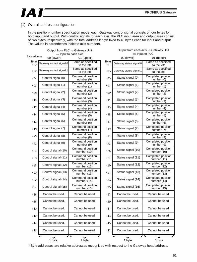
61
PROFIBUS Gateway
(1) Overall address configuration
In the position-number specification mode, each Gateway control signal consists of four bytes for both input and output. With control signals for each axis, the PLC input area and output area consist of two bytes, respectively, with the total address length fixed to 48 bytes each for input and output. The values in parentheses indicate axis numbers.
Output from PLC ⇒ Gateway Unit ⇒ Input to each axis
Output from each axis ⇒ Gateway Unit ⇒ Input to PLC
Byte address 00 (lower) 01 (upper) 00 (lower) 01 (upper)
Gateway control signal 0
Gateway control signal 1
Control signal (0)
Control signal (1)
Control signal (2)
Control signal (3)
Control signal (4)
Control signal (5)
Control signal (6)
Control signal (7)
Control signal (8)
Control signal (9)
Control signal (10)
Control signal (11)
Control signal (12)
Control signal (13)
Control signal (14)
Control signal (15)
Cannot be used.
Cannot be used.
Cannot be used.
Cannot be used.
Cannot be used.
Cannot be used.
Cannot be used.
Cannot be used.
Cannot be used.
Cannot be used.
Cannot be used.
Cannot be used.
Same as specified to the left
Command position number (0)
Same as specified to the left
Command position number (1)
Command position number (2)
Command position number (3)
Command position number (4)
Command position number (5)
Command position number (6)
Command position number (7)
Command position number (8)
Command position number (9)
Command position number (10)
Command position number (11)
Command position number (12)
Command position number (13)
Command position number (14)
Command position number (15)
Gateway status signal 0
Same as specified to the left
Same as specified to the left
Gateway status signal 1
Status signal (0)
Status signal (1)
Status signal (2)
Status signal (3)
Status signal (4)
Status signal (5)
Status signal (6)
Status signal (7)
Status signal (8)
Status signal (9)
Status signal (10)
Status signal (11)
Status signal (12)
Status signal (13)
Status signal (14)
Status signal (15)
Cannot be used.
Cannot be used.
Cannot be used.
Cannot be used.
Cannot be used.
Cannot be used.
Cannot be used.
Cannot be used.
Cannot be used.
Cannot be used.
Cannot be used.
Cannot be used.
Completed position number (0)
Completed position number (1)
Completed position number (2)
Completed position number (3)
Completed position number (4)
Completed position number (5)
Completed position number (6)
Completed position number (7)
Completed position number (8)
Completed position number (9)
Completed position number (10)
Completed position number (11)
Completed position number (12)
Completed position number (13)
Completed position number (14)
Completed position number (15)
1 byte 1 byte 1 byte 1 byte
* Byte addresses are relative addresses recognized with respect to the Gateway head address.

62
PROFIBUS Gateway
(2) Assignment for each axis
With I/O signals for each axis, the PLC input area and output area consist of two bytes, respectively. Control and status signals consist of ON/OFF signal bits. Command position and completed position numbers are treated as one-byte (eight-bit) binary data. Specify command position numbers within the position number range set for each controller axis.
PLC output PLC input
* Byte addresses are relative addresses recognized with respect to the Gateway head address. Byte: Gateway head address n: Axis number (0 to 15)
Byte address
Control signal
Command position number
Byte address
Status signal
Completed position number
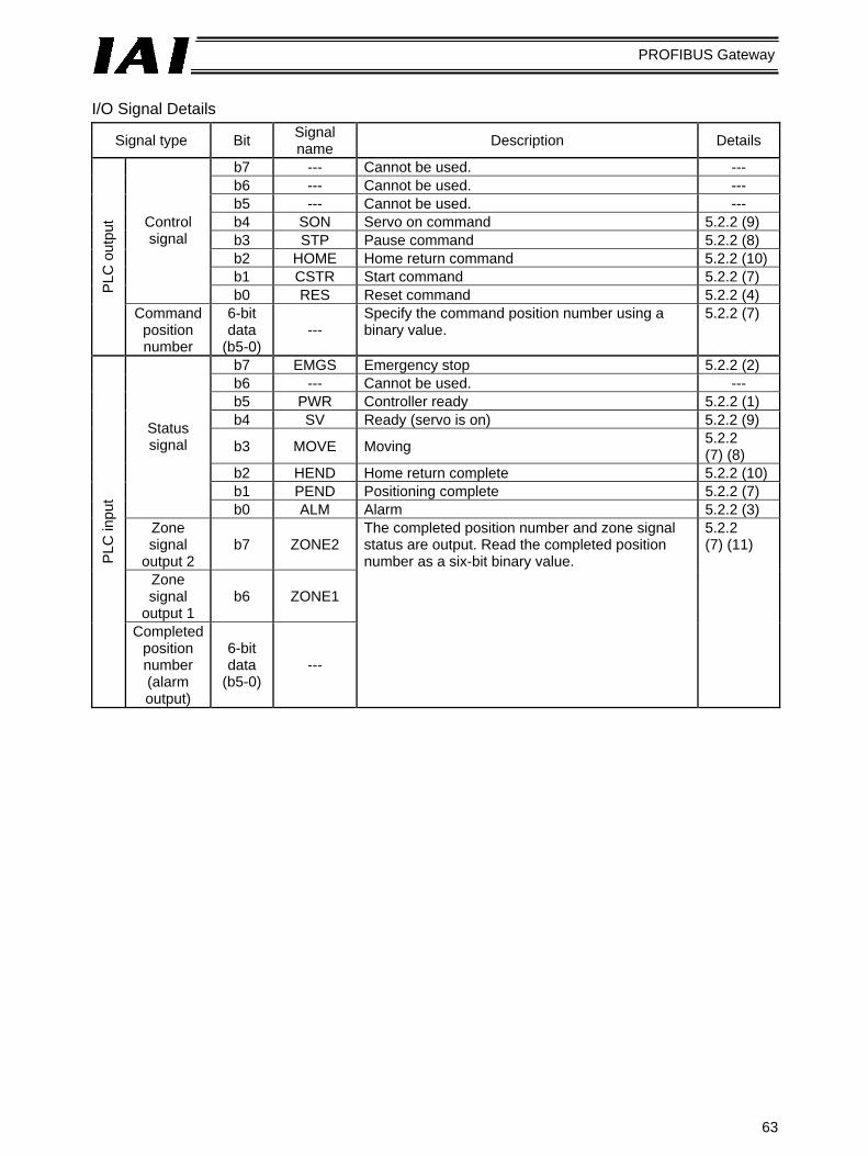
63
PROFIBUS Gateway
I/O Signal Details
Signal type Bit Signal name Description Details
b7 --- Cannot be used. --- b6 --- Cannot be used. --- b5 --- Cannot be used. --- b4 SON Servo on command 5.2.2 (9) b3 STP Pause command 5.2.2 (8) b2 HOME Home return command 5.2.2 (10) b1 CSTR Start command 5.2.2 (7)
Control signal
b0 RES Reset command 5.2.2 (4) PLC
out
put
Command position number
6-bit data
(b5-0) ---
Specify the command position number using a binary value.
5.2.2 (7)
b7 EMGS Emergency stop 5.2.2 (2) b6 --- Cannot be used. --- b5 PWR Controller ready 5.2.2 (1) b4 SV Ready (servo is on) 5.2.2 (9)
b3 MOVE Moving 5.2.2 (7) (8)
b2 HEND Home return complete 5.2.2 (10) b1 PEND Positioning complete 5.2.2 (7)
Status signal
b0 ALM Alarm 5.2.2 (3) Zone signal
output 2 b7 ZONE2
Zone signal
output 1 b6 ZONE1
PLC
inpu
t
Completed position number (alarm output)
6-bit data
(b5-0) ---
The completed position number and zone signal status are output. Read the completed position number as a six-bit binary value.
5.2.2 (7) (11)
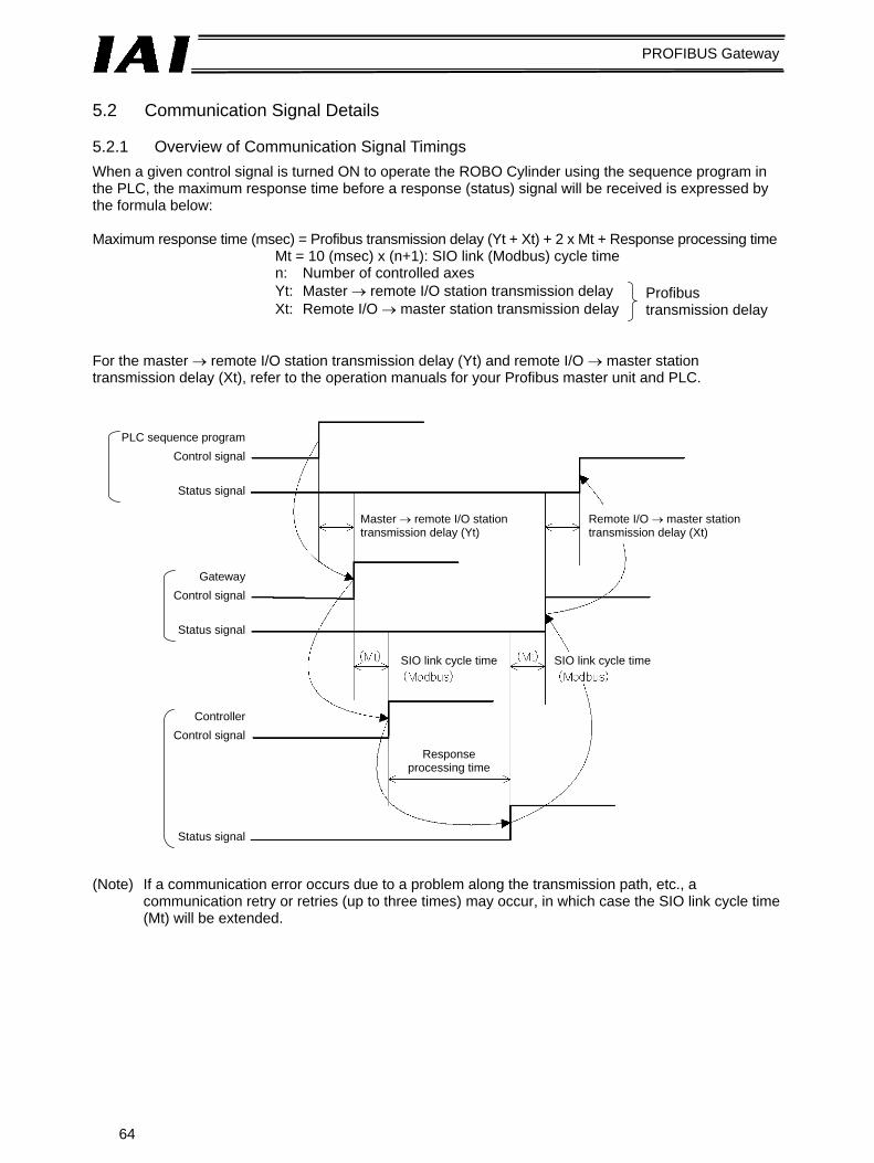
64
PROFIBUS Gateway
5.2 Communication Signal Details 5.2.1 Overview of Communication Signal Timings When a given control signal is turned ON to operate the ROBO Cylinder using the sequence program in the PLC, the maximum response time before a response (status) signal will be received is expressed by the formula below: Maximum response time (msec) = Profibus transmission delay (Yt + Xt) + 2 x Mt + Response processing time
Mt = 10 (msec) x (n+1): SIO link (Modbus) cycle time n: Number of controlled axes Yt: Master → remote I/O station transmission delay Xt: Remote I/O → master station transmission delay
For the master → remote I/O station transmission delay (Yt) and remote I/O → master station transmission delay (Xt), refer to the operation manuals for your Profibus master unit and PLC. (Note) If a communication error occurs due to a problem along the transmission path, etc., a
communication retry or retries (up to three times) may occur, in which case the SIO link cycle time (Mt) will be extended.
Profibus transmission delay
PLC sequence programControl signal
Status signal
Master → remote I/O station transmission delay (Yt)
Remote I/O → master station transmission delay (Xt)
GatewayControl signal
Status signal
ControllerControl signal
Status signal
SIO link cycle time SIO link cycle time
Response processing time

65
PROFIBUS Gateway

66
PROFIBUS Gateway
5.2.2 Communication Signals and Operation Timings (1) Controller ready (PWR)
This signal turns ON when the controller has become ready following the power on.
Function This signal turns ON once the controller has been successfully initialized and become ready following the power on, regardless of whether or not an alarm is present or the servo is on or off. Even if an alarm is present, PWR is always ON as long as the controller is ready. PWR is synchronized with the status indicator LED (green) on the front face of the controller.
(2) Emergency stop (EMGS)
This signal turns ON when the controller has actuated an emergency stop.
Function This signal turns ON when the controller has actuated an emergency stop due to occurrence of a controller alarm or triggering of the emergency stop circuit (refer to 4.3.1), or the motor drive power has been cut off. EMGS will turn OFF once the emergency stop is cancelled.
(3) Alarm (ALM)
This signal turns ON when the controller’s protective circuit (function) has detected an error.
Function This signal turns ON when the controller has detected an error and its protective circuit (function) has actuated. It can be turned OFF by turning the reset (RES) signal ON after removing the cause of the alarm (excluding cold-start level alarms). When an alarm is detected, the ALM LED (red) on the front face of the alarm will illuminate. This LED remains unlit while the controller is normal. With the ERC2, the LED at the top of the motor unit will illuminate in red. The LED will return to green once the servo is turned on.
(4) Reset (RES)
This signal has two functions. It can be used to reset controller alarms or cancel the remaining travel distance while the actuator is paused.
Function
[1] If an alarm is present, the alarm signal can be reset by turning this signal ON after removing the cause of the alarm (excluding cold-start level alarms).
[2] Turning this signal ON while the actuator is paused will cancel the remaining travel distance.

67
PROFIBUS Gateway
(5) Positioning operation in the numerical specification mode
(Position data, current position data, CSTR, PEND, MOVE, acceleration/deceleration data, speed data)
A function is provided to operate the ROBO Cylinder by writing the target position data, acceleration/deceleration data and speed data to the link registers in the PLC, without using the position table in the controller.
Function
a. Positioning operation This function is effective when the numerical specification mode is selected.
[1] Set the target position data in the position data specification register. [2] Turn CSTR (start) ON the moment [1] occurs or briefly thereafter (≥ 0).
In a normal condition, turn CSTR ON while PEND (positioning complete) is ON or MOVE (moving signal) is OFF. The target position data is sent to the controller at the ON edge of CSTR (leading edge of the signal).
[3] PEND turns OFF tdpf after CSTR has turned ON. [4] Cause CSTR to turn OFF upon turning OFF of PEND or turning ON of MOVE (moving).
Do not change the target position data unless CSTR turns OFF. [5] MOVE turns ON the moment PEND turns OFF or within 1 Mt thereafter. [6] The current position data is constantly updated. PEND turns ON the moment the current
position is updated or within 1 Mt thereafter, as long as the remaining travel distance is within the range of controller parameter No. 10, “Default in-position band” and CSTR is OFF. To read the stopped position data after completion of positioning, therefore, wait for an appropriate time (time needed for the actuator to complete the remaining travel distance) after PEND has turned ON. Also note that even when the actuator is stopped, the current position data may still change slightly due to vibration, etc., Consider this change when handling position data.
[7] MOVE turns OFF the moment PEND turns ON or within 1 Mt thereafter. [8] The target position data can be changed during movement.
To change the target position data during movement, change the target position data, wait for a while (longer than the PLC scan time), and then turn CSTR ON. In this case, keep CSTR ON for tdpf or longer. Also provide a minimum interval of 1 Mt after CSTR turns OFF until it turns ON again.

68
PROFIBUS Gateway
[1]
[2] [4]
[3] [4]
[5]
[6] [7]
Position data setting
Current position

69
PROFIBUS Gateway
b. Acceleration/deceleration and speed data specification
This function is effective when the numerical specification mode is selected.
[1] Set the acceleration/deceleration and speed data in the respective specification registers simultaneously as or before setting the target position data in a. If acceleration/deceleration is not set, the setting of parameter No. 9, “Default acceleration/deceleration” will be applied. If speed is not set or the set speed is “0,” the actuator will remain stopped. No alarm will generate.
[2] The acceleration/deceleration and speed data is sent to the controller together with the target position data at the ON edge of CSTR (start) (leading edge of the signal).
[3] The acceleration/deceleration or speed data can be changed during movement. To change the acceleration/deceleration or speed data during movement, change the acceleration/deceleration or speed data, and then turn CSTR ON. In this case, keep CSTR ON for tdpf or longer. Also provide a minimum interval of 1 Mt after CSTR turns OFF until it turns ON again. If the set speed is changed to “0” during movement, the actuator will decelerate to a stop. No alarm will generate.
Caution
1. Target position data must be set even if you only want to change the acceleration/deceleration or speed data during movement.
2. Acceleration/deceleration or speed data must be set even if you only want to change the target position during movement.

70
PROFIBUS Gateway
[1]
[2] [3]
Speed and acceleration/deceleration
setting
Actuator speed
Speed n2
Speed n3
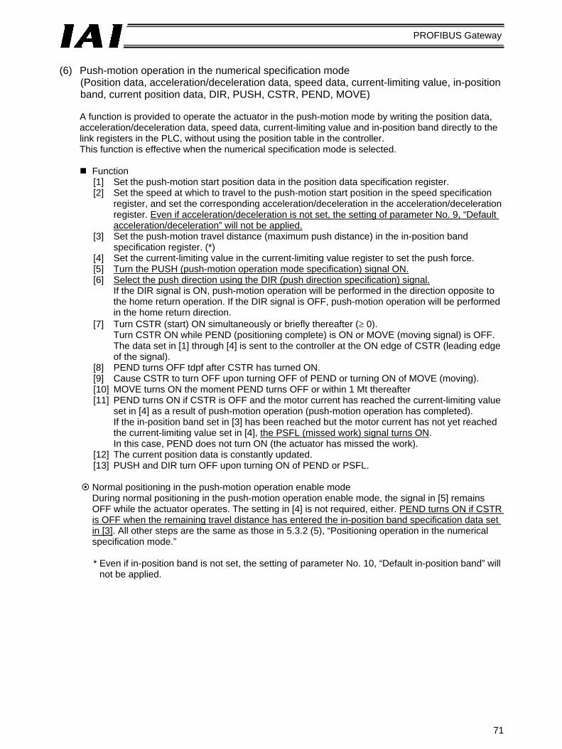
71
PROFIBUS Gateway
(6) Push-motion operation in the numerical specification mode
(Position data, acceleration/deceleration data, speed data, current-limiting value, in-position band, current position data, DIR, PUSH, CSTR, PEND, MOVE)
A function is provided to operate the actuator in the push-motion mode by writing the position data, acceleration/deceleration data, speed data, current-limiting value and in-position band directly to the link registers in the PLC, without using the position table in the controller. This function is effective when the numerical specification mode is selected.
Function
[1] Set the push-motion start position data in the position data specification register. [2] Set the speed at which to travel to the push-motion start position in the speed specification
register, and set the corresponding acceleration/deceleration in the acceleration/deceleration register. Even if acceleration/deceleration is not set, the setting of parameter No. 9, “Default acceleration/deceleration” will not be applied.
[3] Set the push-motion travel distance (maximum push distance) in the in-position band specification register. (*)
[4] Set the current-limiting value in the current-limiting value register to set the push force. [5] Turn the PUSH (push-motion operation mode specification) signal ON. [6] Select the push direction using the DIR (push direction specification) signal.
If the DIR signal is ON, push-motion operation will be performed in the direction opposite to the home return operation. If the DIR signal is OFF, push-motion operation will be performed in the home return direction.
[7] Turn CSTR (start) ON simultaneously or briefly thereafter (≥ 0). Turn CSTR ON while PEND (positioning complete) is ON or MOVE (moving signal) is OFF. The data set in [1] through [4] is sent to the controller at the ON edge of CSTR (leading edge of the signal).
[8] PEND turns OFF tdpf after CSTR has turned ON. [9] Cause CSTR to turn OFF upon turning OFF of PEND or turning ON of MOVE (moving). [10] MOVE turns ON the moment PEND turns OFF or within 1 Mt thereafter [11] PEND turns ON if CSTR is OFF and the motor current has reached the current-limiting value
set in [4] as a result of push-motion operation (push-motion operation has completed). If the in-position band set in [3] has been reached but the motor current has not yet reached the current-limiting value set in [4], the PSFL (missed work) signal turns ON. In this case, PEND does not turn ON (the actuator has missed the work).
[12] The current position data is constantly updated. [13] PUSH and DIR turn OFF upon turning ON of PEND or PSFL.
Normal positioning in the push-motion operation enable mode During normal positioning in the push-motion operation enable mode, the signal in [5] remains OFF while the actuator operates. The setting in [4] is not required, either. PEND turns ON if CSTR is OFF when the remaining travel distance has entered the in-position band specification data set in [3]. All other steps are the same as those in 5.3.2 (5), “Positioning operation in the numerical specification mode.”
* Even if in-position band is not set, the setting of parameter No. 10, “Default in-position band” will
not be applied.

72
PROFIBUS Gateway
[1]
[2]
[3]
[4]
[5]
[6]
[7]
[8] [9]
[10] [12]
[11]
[13]
Position data setting
Speed and acceleration/deceleration
setting
In-position band setting
Current position
Current-limiting value setting

73
PROFIBUS Gateway
(7) Position-number specification operation
(Command position number, completed position number, CSTR, PEND, MOVE)
This function is effective when the position-number specification operation mode is selected.
Function The actuator is operated by specifying position data in the controller’s position table beforehand, and specifying a desired position number using the link register in the PLC. The push-motion operation, speed change operation during movement, and pitch feed by relative coordinate specification, are same as the corresponding operations in the PIO mode (using the I/O cable). Refer to the operation manual for the RCP2 or ERC.
[1] Set the position number in the command position number register. [2] Turn CSTR (start) ON simultaneously on briefly thereafter (≥ 0). [3] PEND (positioning complete) turns OFF tdpf after CSTR has turned ON. [4] Cause CSTR to turn OFF upon turning OFF of PEND or turning ON of MOVE (moving). [5] MOVE turns ON the moment PEND turns OFF or within 1 Mt thereafter [6] The completed position number and PEND are output if CSTR is OFF when the remaining travel
distance has entered the range set in controller parameter No. 10, “Default in-position band.” To read the completed position number after completion of positioning, therefore, wait for an appropriate time (time needed for the actuator to complete the remaining travel distance) after PEND has turned ON.

74
PROFIBUS Gateway
[1]
[2]
[3] [4]
[5]
[6]
Command position number
Completed position number

75
PROFIBUS Gateway
(8) Pause (STP, MOVE)
This function is used to pause the axis while moving.
Function The STP (pause) signal can be used to stop and restart axis movement. The axis stops moving while the STP signal is ON. The relationship of the STP signal and MOVE (moving) signal is shown below.
(9) Servo on (SON, SV)
This signal is used to set the motor ready. When the servo is turned on, the SV LED (green) on the front face of the controller will illuminate. With the ERC2-SE, the LED at the top of the motor unit will illuminate. The SV (ready) signal is synchronized with the indication of this LED.
Function
The controller servo can be turned on/off using the SON (servo on) signal. The controller servo remains on and the actuator can be operated while the SON signal is ON. The relationship of the SON signal and SV signal is shown below.
(10) Home return (HOME, HEND)
a. Standard specification (incremental) Home return is performed at the ON edge of the HOME (home return) signal (leading edge of the signal). When the home return has completed, the HEND (home return complete) signal turns ON. Turn the HOME signal OFF when the HEND signal has turned ON. Even after home return has been completed once, another home return can be performed using the HOME signal.
tdicm ≤ Acceleration/deceleration tdicp ≤ Yt + 2Mt + Xt + 6 (msec)

76
PROFIBUS Gateway
Caution
1. If, in the position-number specification mode a positioning command to a given position is issued without performing any home return following the power on, the actuator will perform home return and then perform the positioning operation. Thereafter, home return will not be performed prior to each positioning operation.
2. If the aforementioned operation is performed in a mode other than the position-number specification mode, error code 83, “Alarm home ABS (absolute position movement command before completion of home return)” will generate.
b. Absolute specification (optional)
With the absolute controller, perform an absolute reset using the teaching pendant or PC software only once after the controller has been started for the first time. Once an absolute reset is done, you need not perform home return every time the power is turned on. This section explains how to use the home return signal to perform an absolute reset. (Refer to the operation manual for the controller for details on the absolute reset. The ERC2 does not support the following procedure.) [1] When the controller power is turned on, the ALM LED (red) on the controller should illuminate.
The alarm (ALM) signal is ON, and the alarm code (PM8 to PM1) signals output “1101.” [2] If the slider or rod is positioned near the home-side mechanical end or home, move it by hand to
the opposite direction until the slider/rod is sufficiently away from the mechanical end or home. If the actuator is equipped with a brake, release the brake using the brake release switch on the controller. After the slider/rod has been moved, actuate the brake again.
[3] Turn the reset (RES) signal ON (≥ Mt). [4] Reset the controller’s emergency stop or turn on the motor drive power. The ALM LED (red) on
the controller should illuminate. [5] Turn the servo on (SON) signal ON. The RUN LED (green) on the controller will illuminate with
the servo turned on. The positioning completed (PEND) signal and servo on (SV) signal will be output. [6] Home return is performed at the ON edge of the home return (HOME) signal (leading edge of the
signal). When the home return has completed, the home return complete (HEND) signal turns ON and the absolute coordinates are established where the home is defined as the position at which the home return has completed. Turn the home return (HOME) signal OFF when the home return complete (HEND) signal has turned ON. Even after home return has been completed once, another home return can be performed using the home return (HOME) signal.

77
PROFIBUS Gateway
(11) Zone (ZONE1, ZONE2)
In the position-number specification mode, two zone signals can be output inside arbitrary zones set by parameters. The ZONE1 (zone 1) signal turns ON inside the zone set by parameter No. 1 (Zone boundary 1+) and No. 2 (Zone boundary 1-). The ZONE2 (zone 2) signal turns ON inside the zone set by parameter No. 23 (Zone boundary 2+) and No. 24 (Zone boundary 2-).
Caution
1. Zone signals are not supported in any other mode but the position-number specification mode. 2. Use zone signals after home return has completed (while the HEND signal is ON). As long as the
HEND (home return complete) signal is ON, zone signals are effective even when the servo is or an emergency stop is being actuated.
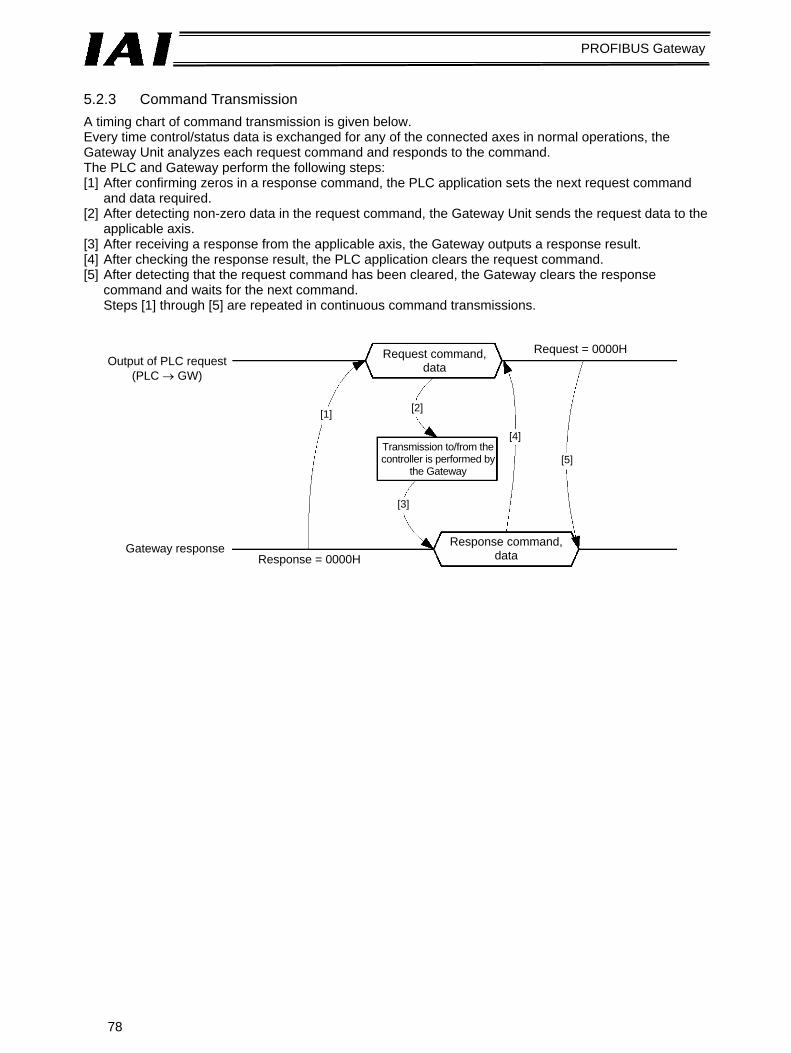
78
PROFIBUS Gateway
5.2.3 Command Transmission A timing chart of command transmission is given below. Every time control/status data is exchanged for any of the connected axes in normal operations, the Gateway Unit analyzes each request command and responds to the command. The PLC and Gateway perform the following steps: [1] After confirming zeros in a response command, the PLC application sets the next request command
and data required. [2] After detecting non-zero data in the request command, the Gateway Unit sends the request data to the
applicable axis. [3] After receiving a response from the applicable axis, the Gateway outputs a response result. [4] After checking the response result, the PLC application clears the request command. [5] After detecting that the request command has been cleared, the Gateway clears the response
command and waits for the next command. Steps [1] through [5] are repeated in continuous command transmissions.
[1] [2]
[3]
[4]
[5]
Output of PLC request (PLC → GW)
Request command, data
Request = 0000H
Transmission to/from the controller is performed by
the Gateway
Gateway response Response = 0000H
Response command, data

79
PROFIBUS Gateway
5.3 System Design The following settings are required for the Profibus master PLC to communicate with the controller via the Gateway. [1] Controller settings for enabling SIO (Modbus) communication between the Gateway Unit and the controller [2] PLC and Gateway Unit settings for enabling Profibus communication between the PLC and the
Gateway Unit 5.3.1 Settings for Controller Communication For the controller to be able to communicate with the Gateway, the settings specified below must be performed. (1) Set a unique axis number in a range of 0 to 15.
Take note that the range of settable axis numbers varies depending on the operation mode of the Gateway Unit.
(2) Set parameters
[1] Set parameter No. 16, “SIO baud rate” to “230400” (230.4 kbps). SIO communication cannot be performed at any other baud rate but 230.4 kbps.
[2] Set parameter No. 17, “Slave transmitter activation minimum delay” to “5” or less. To turn the communication cycle at the maximum speed, set “0.”
The figure below shows the user parameter setting screen of the PC software.

80
PROFIBUS Gateway
5.3.2 Settings for Profibus-DP Communication For the Gateway Unit to be able to communicate with the master station, the settings specified below must be performed. The following items must be consistent between the master station and the Gateway Unit.
: ON X: OFF Item Gateway Unit setting PLC master setting
Unit type → Universal module *1
I/OTYPE → Out-Input Address Address setting switch Profibus unit address
Mode setting switch SW1 I/O size NO. 4 3 2 1 Output
(bytes) Input
(bytes)
1 X X X X 52 28 Numerical, 4 axes 2 X X X 76 40 Numerical, 6 axes 3 X X X 100 52 Numerical, 8 axes 4 X 124 64 Numerical, 10 axes 5 X X 196 100 Numerical, 16 axes *2 6 X X X 48 48 POS, 16 axes
7 X X X 160 160 Simple direct/position-number specification mode, large
8 X X 128 128 Simple direct/position-number specification mode, middle
Assignments
9 X X 64 64 Simple direct/position-number specification mode, small
*1) Multiple modules, each consisting of m/n input/output bytes, may be set without space between the
I/O addresses. If function blocks are used, the head address numbers must be continuous and the same between input and output sides.
*2) When connecting 10 or more axes, the PLC must be the S7-400 or S7-318-2 (Siemens).

81
PROFIBUS Gateway
5.3.3 Creation of Network Configuration (1) Installing a GDS file
To define the Gateway in the STEP 7’s HW Config screen, the Gateway’s GDS file must be imported beforehand. The GDS file to be imported is HMS_1003.GDS. This file can be downloaded from IAI’s website.
<GDS file import>
When the GDS file has been imported successfully, a new level called “ANYBUS-PDP” will be created in the catalog window of the HW Config screen, as shown below.
<Catalog window showing the imported GDS file>

82
PROFIBUS Gateway
(2) Inserting a Profibus-DP mater system
Select a Profibus-DP master and insert it as the master system, as shown below.
<Master system insertion>
When the Profibus-DP master has been inserted successfully, it will be displayed as the master system, as shown below.
<After the Profibus-DP master system has been inserted>

83
PROFIBUS Gateway
(3) Inserting a Gateway rack in the network
Drag and drop “ANYBUS-S PDP” in the catalog window over to the master system and insert it as a module, as shown below. The address will be set automatically. To change the address that has been set automatically, do so in the Properties dialog box. This address must correspond to the address switch setting of the Gateway, as mentioned earlier.
<Rack insertion into the network> (4) Setting the I/O assignments – Inserting a universal module
Insert a universal module into the rack inserted in the previous step, as shown below. Since the maximum input/output bytes of the universal module are 64 each, another universal module must be inserted if there are 10 or more axes.
<Universal module insertion into the rack>

84
PROFIBUS Gateway
Double-clicking the inserted universal module will open the Properties dialog box shown below. Set “Out-input” under I/O Type, and then enter the output length and input length according to the table in 5.3.2. The example below assumes connection of four axes. The address will be set automatically, but it can be changed if necessary.
<I/O length settings for the universal module>
Clicking OK will apply the settings to the universal module, as shown below.
<Universal module with its I/O lengths set>
All settings are now complete. You can now download them to the PLC.

85
PROFIBUS Gateway
(5) Setting for I/O data consistency
With normal settings, consistency of Profibus IQ data is guaranteed in units of words and bytes. It is important that each command code and related parameters in the command area are read or written together. To ensure consistent data access, an applicable item must be set to ensure data consistency in the HW Config screen, and data must be accessed using the SFC14 and SFC15. With command function blocks, the first five words in the command area are accessed using the SFC14/15. Accordingly, the data consistency setting must be performed in the IQ areas for the applicable five words, as shown in the example below.
Double-click a desired line or select Object Propertiesin the pull-down menu.
Set “Total length,” instead of a unit (Byte or Word) under Consistent over.

86
PROFIBUS Gateway
5.3.4 Example of Actual Assignments After completing the I/O assignments in the preceding sections with all pins of the mode setting switch SW1 set to the OFF positions (numerical, 4 axes), the actual addresses should look like those shown below. The S7-300 PLC guarantees consistency of I/O image and data at the data width (byte, word or double words) defined in the program. If data consistency must be guaranteed throughout the I/O areas, one way is to copy/write the I/O areas to the memory area (M area) using system function blocks SFC14 and SFC15, and then specify the M area in the program. For details on this method, refer to the applicable document published by HMS: http://www.anybus.com/eng/upload/AnyBus-S-0012-Siemens%20Step7%20and%20AnyBus-S.pdf
PLC output
Gateway control word 0 Gateway control word 1 Axis (0) target position
Axis (0) push rate Axis (0) speed
Axis (0) acceleration/deceleration
Axis (0) in-position band Axis (0) control signal
Axis (1) target position Axis (1) push rate
Axis (1) speed Axis (1) acceleration/deceleration
Axis (1) in-position band Axis (1) control signal
Axis (2) target position Axis (2) push rate
Axis (2) speed Axis (2) acceleration/deceleration
Axis (2) in-position band Axis (2) control signal
Axis (3) target position Axis (3) push rate
Axis (3) speed Axis (3) acceleration/deceleration
Axis (3) in-position band Axis (3) control signal
PLC input
Gateway status word 0 Gateway status word 1
Axis (0) status signal Axis (0) current position
Cannot be used.
Cannot be used. Axis (1) status signal
Axis (1) current position Cannot be used.
Cannot be used. Axis (2) status signal
Axis (2) current position Cannot be used.
Cannot be used. Axis (3) status signal
Axis (3) current position Cannot be used.
Cannot be used.
Based on the above, the control signals, status signals, direct specification data and current position of axis (3) will be addressed as shown in the table below.
Output signal/data name Address Data length Address Data length Input signal/data Target position Push rate Speed Acceleration/deceleration In-position band
3 bytes 1 byte 3 bytes 1 byte 3 bytes 1 bit 1 bit 1 bit 1 bit 1 bit 1 bit 1 bit 1 bit
1 bit 1 bit 1 bit 1 bit 1 bit 1 bit 1 bit 1 bit 3 bytesCurrent position

87
PROFIBUS Gateway
5.4 Supported S7 Function Blocks/Functions The function blocks/functions provided by IAI allow for easy programming without the need to worry about detailed I/O assignments. The basic functions provided include this addressing function and a range check function for certain input parameters. These function blocks/functions can be utilized only with the Siemens S7 Series. Short sample programs are provided in the appendix for reference. The following function blocks/functions are supported.
Name Overview Note
GW CTL ** Start/stop Gateway-controller communication and specify a linked axis.
RC NVC ** Execute movement by numerical specification.
RC ESYNC ** Execute movement by simple numerical specification.
RC BCMOVP ** Broadcast a movement start command. *1
RC READ ** Read RC data (POS table data, current position, alarm code). *1
RC WRITE ** Write RC data (POS table data). *1
RC PROM ** Convert position data into ROM. *1
RC PMSL ** Switch between PIO and Modbus. *1
*1) Use only one of these function blocks at a time, as they all access the same area. These function blocks control command transmission, but do not monitor the response time. The response time must be monitored by the application if necessary.
*2) In the common input parameter LADDR, set the Gateway I/O head addresses
set in HW Config. (The head address numbers must be continuous and the same between input and output sides. Refer to 5.3.2, “Settings for Profibus-DP Communication.”) For details on the I/O parameters for each function block, refer to “Address Assignments.”
*3) All function blocks/functions use address register 1 (AR1). Exercise caution if this
register is used by the application.
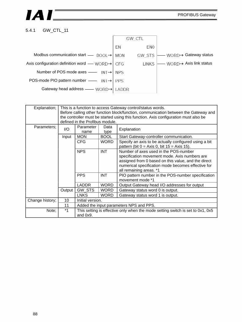
88
PROFIBUS Gateway
5.4.1 GW_CTL_11
Explanation; This is a function to access Gateway control/status words. Before calling other function block/function, communication between the Gateway and the controller must be started using this function. Axis configuration must also be defined in the Profibus module.
I/O Parameter name
Data type Explanation
MON BOOL Start Gateway-controller communication. CFG WORD Specify an axis to be actually configured using a bit
pattern (bit 0 = Axis 0, bit 15 = Axis 15). NPS INT Number of axes used in the POS-number
specification movement mode. Axis numbers are assigned from 0 based on this value, and the direct numerical specification mode becomes effective for all remaining areas. *1
PPS INT PIO pattern number in the POS-number specification movement mode *1
Input
LADDR WORD Output Gateway head I/O addresses for output GW_STS WORD Gateway status word 0 is output.
Parameters;
Output LNKS WORD Gateway status word 1 is output.
10 Initial version. Change history; 11 Added the input parameters NPS and PPS.
Note; *1 This setting is effective only when the mode setting switch is set to 0x1, 0x5 and 0x9.
Modbus communication start
Axis configuration definition word
Number of POS mode axes
POS-mode PIO pattern number
Gateway head address
Gateway status
Axis link status
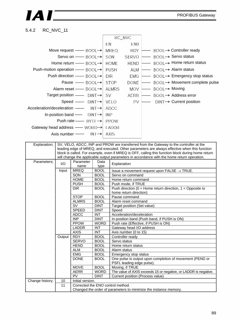
89
PROFIBUS Gateway
5.4.2 RC_NVC_11
Explanation; SV, VELO, ADCC, INP and PROW are transferred from the Gateway to the controller at the leading edge of MREQ, and executed. Other parameters are always effective when this function block is called. For example, even if MREQ is OFF, calling this function block during home return will change the applicable output parameters in accordance with the home return operation.
I/O Parameter name
Data type Explanation
MREQ BOOL Issue a movement request upon FALSE → TRUE. SON BOOL Servo on command HOME BOOL Home return command PUSH BOOL Push mode, if TRUE DIR BOOL Push direction (0 = Home return direction, 1 = Opposite to
home return direction) STOP BOOL Pause command ALMRS BOOL Alarm reset command SV DINT Target position (Set value) SPEED DINT Speed ADCC INT Acceleration/deceleration INP DINT In-position band (Push band, if PUSH is ON) PPOW WORD Push rate (Effective, if PUSH is ON) LADDR INT Gateway head I/O address
Input
AXIS INT Axis number (0 to 15) RDY BOOL Controller ready SERVO BOOL Servo status HEND BOOL Home return status ALM BOOL Alarm status EMG BOOL Emergency stop status DONE BOOL One pulse is output upon completion of movement (PEND or
PSFL leading edge pulse). MOVE BOOL Moving, if TRUE AERR WORD The value of AXIS exceeds 15 or negative, or LADDR is negative.
Parameters;
Output
PV DINT Current position (Process value) 10 Initial version. Change history; 11 Corrected the ENO control method.
Changed the order of parameters to minimize the instance memory.
Move request Servo on
Home return Push-motion operation
Push direction Pause
Alarm reset Target position
Speed Acceleration/deceleration
In-position band Push rate
Gateway head address Axis number
Controller ready Servo status Home return status
Alarm status Emergency stop status Movement complete pulse Moving
Address error Current position

90
PROFIBUS Gateway
5.4.3 RC_ESYNC_00
Explanation; SV and PARA_N are transferred from the Gateway to the controller at the leading edge of MREQ, and executed. Other parameters are always effective when this function block is called. For example, even if MREQ is OFF, calling this function block during home return will change the applicable output parameters in accordance with the home return operation.
I/O Parameter name
Data type Explanation
MREQ BOOL Issue a movement request upon FALSE → TRUE. SON BOOL Servo on command HOME BOOL Home return command SV DINT Target position (Set value) PARA_N INT Movement parameter (POS) number STOP BOOL Pause command ALMRS BOOL Alarm reset command LADDR INT Gateway head I/O address
Input
AXIS INT Axis number (0 to 15) RDY BOOL Controller ready SERVO BOOL Servo status HEND BOOL Home return status ALM BOOL Alarm status EMG BOOL Emergency stop status DONE BOOL One pulse is output upon completion of movement
(PEND or PSFL leading edge pulse). MVES BOOL Movement start pulse
(PEND or PSFL trailing edge pulse). PV DINT Current position (Process value)
Parameters;
Output
AERR WORD The value of AXIS exceeds 15 or negative, or LADDR is negative.
Change history; 00 Initial version.
Move request
Servo on
Home return
Target position
Movement parameter number
Pause
Alarm reset
Gateway head address
Axis number
Controller ready Servo status
Home return status
Alarm status
Emergency stop status
Movement complete pulse
Current position
Address error
Movement start pulse

91
PROFIBUS Gateway
5.4.4 RC_BCMOVP_00
Explanation; The Gateway broadcasts the start command for the specified POS to the specified group at the leading edge of REQ. The execution complete pulse of this function block indicates that issuance of this command has completed, not that movement of each axis has completed. To check if each axis has completed its movement, check the status bit of each axis.
I/O Parameter name
Data type Explanation
REQ BOOL Issue an execution request upon FALSE → TRUE. POS WORD Position number value. Settable values vary
depending on the axis. GROUP BYTE Group ID number
Input
LADDR WORD Gateway head I/O address DONE BOOL One pulse is output upon completion of command
issuance. BUSY BOOL The command is being issued.
0000H Successful 0102H Invalid POS number 0103H Invalid command 0201H Communication failed
Parameters;
Output
RESULT WORD Command issuance result code;
0202H Exceptional response Note; 1 This function block uses the SFC14/15. Consistency setting is required for
data corresponding to the first five words in the command area. Change history; 00 Initial version.
Move request
POS number
Group number
Gateway head address
Issuance complete pulse
Executing
Result code

92
PROFIBUS Gateway
5.4.5 RC_READ_00
Explanation; The data specified by POS and DATA_ID is read from the specified axis at the leading edge of REQ. The input parameter POS is effective only when the data type ID is one that relates to the POS table.
I/O Parameter name
Data type Explanation
REQ BOOL Issue an execution request upon FALSE → TRUE. POS INT Position number value. Settable values vary
depending on the axis. 0 Target position (unit: 0.01 mm) 1 In-position band (unit: 0.01 mm) 2 Speed (unit: 0.01 mm/s) 3 Each zone+ (unit: 0.01 mm) 4 Each zone- (unit: 0.01 mm) 5 Acceleration (unit: 0.01 G) 6 Deceleration (unit: 0.01 G) 7 Push rate (FFH = 100%) 8 Threshold % (FFH = 100%) 128 Current value
DATA_ID INT Data type ID;
129 Alarm code LADDR WORD Gateway head I/O address
Input
AXIS BYTE Axis number (0 to 15) DONE BOOL One pulse is output upon completion of command
issuance. BUSY BOOL The command is being issued.
0000H Successful 0102H Invalid POS number 0103H Invalid command 0201H Communication failed 0202H Exceptional response
RESULT WORD Command issuance result code;
1000H Invalid axis number or data ID
Parameters;
Output
DATE DWORD Read data Note; 1 This function block uses the SFC14/15. Consistency setting is required for
data corresponding to the first five words in the command area. Change history; 00 Initial version.
Read request
Position number
Data type ID
Gateway head address
Axis number
Complete pulse
Executing
Result code
Read data

93
PROFIBUS Gateway
5.4.6 RC_WRITE_00
Explanation; The data specified by POS and DATA_ID is written to the specified axis at the leading edge of REQ.
I/O Parameter name
Data type Explanation
REQ BOOL Issue an execution request upon FALSE → TRUE. POS INT Position number value. Settable values vary
depending on the axis. 0 Target position 1 In-position band 2 Speed 3 Each zone+ (DATA: unit: 0.01 mm)4 Each zone- (DATA: unit: 0.01 mm) 5 Acceleration (DATA: unit: 0.01 G) 6 Deceleration (DATA: unit: 0.01 G) 7 Push rate (DATA: FFH = 100%)
DATA_ID INT Data type ID;
8 Threshold % (DATA: FFH = 100%)DATA DWORD Write data LADDR WORD Gateway head I/O address
Input
AXIS BYTE Axis number (0 to 15) DONE BOOL One pulse is output upon completion of command
issuance. BUSY BOOL The command is being issued.
0000H Successful 0102H Invalid POS number 0103H Invalid command 0201H Communication failed 0202H Exceptional response
Parameters;
Output
RESULT WORD Command issuance result code;
1000H Invalid axis number or data ID Note; 1 This function block uses the SFC14/15. Consistency setting is required for
data corresponding to the first five words in the command area. Change history; 00 Initial version.
Write request
Position number
Data type ID
Write data
Gateway head address
Axis number
Complete pulse
Executing
Result code

94
PROFIBUS Gateway
5.4.7 RC_PROM_00
Explanation; A ROM conversion command is issued for the POS data of the specified axis at the leading edge of REQ.
I/O Parameter name Data type Explanation
REQ BOOL Issue an execution request upon FALSE → TRUE. LADDR WORD Gateway head I/O address
Input
AXIS BYTE Axis number (0 to 15) DONE BOOL One pulse is output upon completion of command issuance. BUSY BOOL The command is being issued.
0000H Successful 0103H Invalid command 0201H Communication failed 0202H Exceptional response
Parameters;
Output
RESULT WORD Command issuance result code;
1000H Invalid axis number Note; 1 This function block uses the SFC14/15. Consistency setting is required for data corresponding to
the first five words in the command area. Change history; 00 Initial version.
5.4.8 RC_PMSL_00
Explanation; PIO/Modbus switching is implemented for the specified axis by PMSL at the leading edge of REQ.
I/O Parameter name Data type Explanation
REQ BOOL Issue an execution request upon FALSE → TRUE. 0 PIO (Enable PIO command) PMSL BOOL PIO/Modbus switching
specification 1 Modbus (Disable PIO command) LADDR UNIT Gateway head I/O address
Input
AXIS UNIT Axis number (0 to 15) DONE BOOL One pulse is output upon completion of command issuance. BUSY BOOL The command is being issued.
0000H Successful 0102H Invalid POS number 0103H Invalid command 0201H Communication failed
Parameters;
Output
RESULT WORD Command issuance result code;
0202H Exceptional response Note; 1 This function block uses the SFC14/15. Consistency setting is required for data corresponding to
the first five words in the command area. Change history; 00 Initial version.
ROM conversion request
Gateway head address
Axis number
Complete pulse
Executing
Result code
Control authority switching request
PIO/Modbus switching specification
Gateway head CH number
Axis number
Complete pulse
Executing
Result code

95
PROFIBUS Gateway
Appendix 1. Sample Programs for S7-300 Example of Using RC_NVC_11 and GW_CTL_11
#AnyON is always ON.
GW/controller communication starts (MON).
Axis 0 is configured (W#16#1).
The Gateway I/O head addresses are “0.”
Servo on delay timer
Homing delay timer
The next target position is controlled based on the movement completion pulse (NC0.DONE) output by a FB. The target position changes in the sequence of x0p1 → x0p2 → x0p3 → x0p1, …, every time the NC0.DONE pulse is input.
Online status is checked from the STS_W, LNK_W and RC_NVC_11 (instance name: NC0) outputs.

96
PROFIBUS Gateway
Step1 movement data set (push motion) Target position: 30.00 mm Speed: 100.00 mm/s Acceleration/deceleration: 0.2 Push band: 20.00 mm Push rate: 49% (7F / FF)
Step2 movement data set (normal movement) Target position: 20.00 mm Speed: 100.00 mm/s Acceleration/deceleration: 0.2 Positioning band: 00.10 mm Push rate: 0%
Step3 movement data set (normal movement) Target position: 00.00 mm Speed: 100.00 mm/s Acceleration/deceleration: 0.2 Positioning band: 00.10 mm Push rate: 0%

97
PROFIBUS Gateway
A motion FB for axis 0 is always called. The instance name is “NC0.” Data is sent/received based on NC0.[tentative parameter].
The I/O head addresses are “0.” The axis number is “0.”

98
PROFIBUS Gateway
Appendix 2. Supply Format and Use Procedure of FB/FCt FBs are provided as source files ([Function block name_Version].AWL). The steps to use a provided source file in a user project are explained below.
[1] Select the “Sources” folder, click Insert, and then click External Source....
[2] When the following file selection window opens, select an appropriate source file, and then click Save.
[3] The source file will be imported to the “Sources” folder.

99
PROFIBUS Gateway
[4] Start Symbol Editor, and save the FB RC_NVC under a desired FB number.
[5] Compile the source file.
[6] When the compiling is complete, the registered function block will be generated in the “Blocks” folder.
Now, FB1, namely RC_NVC, can be called from OB1.

RCM-GW-PR, Manual No.: 0107-E, Version MJ0177-1A-E (November 2006)
IAI Industrieroboter GmbH Ober der Röth 4, D-65824 Schwalbach / Taunus
Germany Phone:+49-(0)6196-8895-0Fax: +49-(0)6196-8895-24
E-Mail: [email protected] Internet: http://www.eu.IAI-GmbH.de
IAI America Inc. 2690 W. 237th Street, Torrance, CA 90505, USA Tel.: +1-310-891-6015 Fax: +1-310-891-0815
IAI CORPORATION 645-1 Shimizu Hirose, Shizuoka 424-0102, Japan Tel.: +81-543-64-5105 Fax: +81-543-64-5182
The information contained in this document is subject to change without notice for the purpoe of product improvement. Copyright © 2005. Mar. IAI Corporation. All rights reserved.