profibus interconnection technology - profibus...
TRANSCRIPT
PROFIBUS
Interconnection Technology
Guideline
Version 1.4January 2007
Order No: 2.142

Document Identification: TC2-05-0004 File name: PB-Intercon-Techn_2142_V14_Jan07
Prepared by the PROFIBUS Working Group 6 “Passive Network Components” in the Technical Committee 2 “Communication Profiles”.
The attention of adopters is directed to the possibility that compliance with or adoption of PI (PROFIBUS International) specifications may require use of an invention covered by patent rights. PI shall not be responsible for identifying patents for which a license may be required by any PI specification, or for conducting legal inquiries into the legal validity or scope of those patents that are brought to its attention. PI specifications are prospective and advisory only. Prospective users are responsible for protecting themselves against liability for infringement of patents.
NOTICE:
The information contained in this document is subject to change without notice. The material in this document details a PI specification in accordance with the license and notices set forth on this page. This document does not represent a commitment to implement any portion of this specification in any company's products.
WHILE THE INFORMATION IN THIS PUBLICATION IS BELIEVED TO BE ACCURATE, PI MAKES NO WARRANTY OF ANY KIND, EXPRESS OR IMPLIED, WITH REGARD TO THIS MATERIAL INCLUDING, BUT NOT LIMITED TO ANY WARRANTY OF TITLE OR OWNERSHIP, IMPLIED WARRANTY OF MERCHANTABILITY OR WARRANTY OF FITNESS FOR PARTICULAR PURPOSE OR USE.
In no event shall PI be liable for errors contained herein or for indirect, incidental, special, consequential, reliance or cover damages, including loss of profits, revenue, data or use, incurred by any user or any third party. Compliance with this specification does not absolve manufacturers of PROFIBUS or PROFINET equipment, from the requirements of safety and regulatory agencies (TÜV, BIA, UL, CSA, FCC, IEC, etc.).
PROFIBUS® and PROFINET® logos are registered trade marks. The use is restricted for members of Profibus International. More detailed terms for the use can be found on the web page www.profibus.com/libraries.html. Please select button "Presentations & logos".
In this specification the following key words (in bold text) will be used: may: indicates flexibility of choice with no implied preference. should: indicates flexibility of choice with a strongly preferred implementation. shall: indicates a mandatory requirement. Designers shall implement such
mandatory requirements to ensure interoperability and to claim conformance with this specification.
Publisher: PROFIBUS Nutzerorganisation e.V. Haid-und-Neu-Str. 7 76131 Karlsruhe Germany Phone: +49 (0) 721 / 96 58 590 Fax: +49 (0) 721 / 96 58 589 E-mail: [email protected] Web site: www.profibus.com © No part of this publication may be reproduced or utilized in any form or by any means, electronic or mechanical, including photocopying and microfilm, without permission in writing from the publisher.
PROFIBUS Interconnection Technology Version 1.4
© Copyright PNO 2007 - All Rights Reserved Page 3 of 34 pages
Contents
1 Management Summary - Scope of this document ............................................................4 2 Reference to affected PROFIBUS Guidelines..................................................................6 3 Interconnection technology for PROFIBUS in IP 20 or higher ..........................................7
3.1 Interconnection technology for PROFIBUS standard cables ...................................7 3.2 Interconnection technology for optical fibers ..........................................................9
3.2.1 Connectors for optical fibers (820 nm and 1300 nm) ...................................9 3.2.2 Connectors for polymer fibers and HCS®/PCS fibers (660 nm) ....................9
4 Interconnection technology for IP 65 or higher ..............................................................10 4.1 Interconnection technology for PROFIBUS standard cables (RS-485)...................10
4.1.1 M12 bus connector ..................................................................................10 4.1.2 Connector and tee structure .....................................................................11 4.1.3 Installation ...............................................................................................14
4.2 Interconnection technology for standard PROFIBUS hybrid cable (RS-485) ..........15 4.2.1 Description of the hybrid connector family ................................................15 4.2.2 Description of the system configuration ....................................................16
4.2.2.1 Description of the system configuration (copper – copper standard hybrid cable) ...............................................................16
4.2.2.2 Description of the system configuration (copper – optical fiber standard hybrid cable) ...............................................................18
4.2.3 Implementation and design of the devices ................................................19 4.3 Interconnection technology for standard and hybrid cables (RS-485)....................22
4.3.1 Bus connector for ANSI TIA/EIA-485-A interface ......................................23 4.3.2 System configuration ...............................................................................25 4.3.3 Implementation / Device design................................................................27
4.4 Interconnection technology for IEC 61158-2.........................................................29 4.4.1 Pin assignment of M12 circular connector ................................................29 4.4.2 Connector for asynchronous transmission ................................................30 4.4.3 Connectors for fibre optic cable................................................................31 4.4.4 Implementation ........................................................................................32
PROFIBUS Interconnection Technology Version 1.4
© Copyright PNO 2007 - All Rights Reserved Page 4 of 34 pages
1 Management Summary - Scope of this document
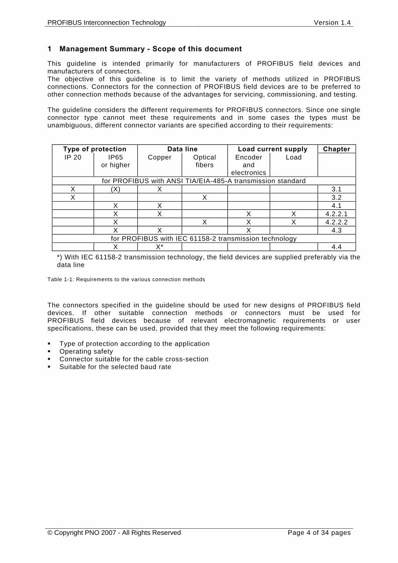
This guideline is intended primarily for manufacturers of PROFIBUS field devices and manufacturers of connectors. The objective of this guideline is to limit the variety of methods utilized in PROFIBUS connections. Connectors for the connection of PROFIBUS field devices are to be preferred to other connection methods because of the advantages for servicing, commissioning, and testing. The guideline considers the different requirements for PROFIBUS connectors. Since one single connector type cannot meet these requirements and in some cases the types must be unambiguous, different connector variants are specified according to their requirements:
Type of protection Data line Load current supply Chapter IP 20 IP65
or higher Copper Optical
fibers Encoder
and electronics
Load
for PROFIBUS with ANSI TIA/EIA-485-A transmission standard X (X) X 3.1 X X 3.2 X X 4.1 X X X X 4.2.2.1 X X X X 4.2.2.2 X X X 4.3
for PROFIBUS with IEC 61158-2 transmission technology X X* 4.4
*) With IEC 61158-2 transmission technology, the field devices are supplied preferably via the data line
Table 1-1: Requirements to the various connection methods
The connectors specified in the guideline should be used for new designs of PROFIBUS field devices. If other suitable connection methods or connectors must be used for PROFIBUS field devices because of relevant electromagnetic requirements or user specifications, these can be used, provided that they meet the following requirements: Type of protection according to the application Operating safety Connector suitable for the cable cross-section Suitable for the selected baud rate
PROFIBUS Interconnection Technology Version 1.4
© Copyright PNO 2007 - All Rights Reserved Page 5 of 34 pages
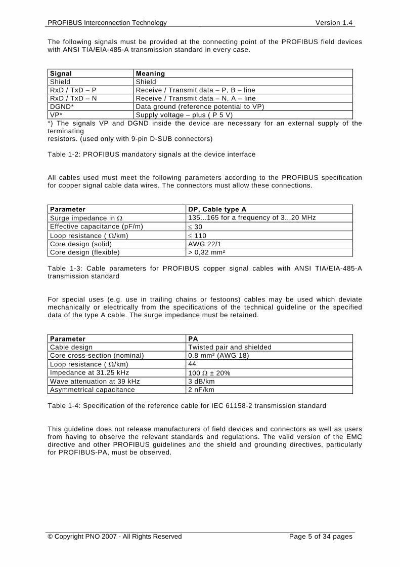
The following signals must be provided at the connecting point of the PROFIBUS field devices with ANSI TIA/EIA-485-A transmission standard in every case. Signal Meaning Shield Shield RxD / TxD – P Receive / Transmit data – P, B – line RxD / TxD – N Receive / Transmit data – N, A – line DGND* Data ground (reference potential to VP) VP* Supply voltage – plus ( P 5 V)
*) The signals VP and DGND inside the device are necessary for an external supply of the terminating resistors. (used only with 9-pin D-SUB connectors) Table 1-2: PROFIBUS mandatory signals at the device interface All cables used must meet the following parameters according to the PROFIBUS specification for copper signal cable data wires. The connectors must allow these connections. Parameter DP, Cable type A Surge impedance in Ω 135...165 for a frequency of 3...20 MHz Effective capacitance (pF/m) ≤ 30 Loop resistance ( Ω/km) ≤ 110 Core design (solid) AWG 22/1 Core design (flexible) > 0,32 mm²
Table 1-3: Cable parameters for PROFIBUS copper signal cables with ANSI TIA/EIA-485-A transmission standard For special uses (e.g. use in trailing chains or festoons) cables may be used which deviate mechanically or electrically from the specifications of the technical guideline or the specified data of the type A cable. The surge impedance must be retained. Parameter PA Cable design Twisted pair and shielded Core cross-section (nominal) 0.8 mm² (AWG 18) Loop resistance ( Ω/km) 44 Impedance at 31.25 kHz 100 Ω ± 20% Wave attenuation at 39 kHz 3 dB/km Asymmetrical capacitance 2 nF/km
Table 1-4: Specification of the reference cable for IEC 61158-2 transmission standard This guideline does not release manufacturers of field devices and connectors as well as users from having to observe the relevant standards and regulations. The valid version of the EMC directive and other PROFIBUS guidelines and the shield and grounding directives, particularly for PROFIBUS-PA, must be observed.

PROFIBUS Interconnection Technology Version 1.4
© Copyright PNO 2007 - All Rights Reserved Page 6 of 34 pages
2 Reference to affected PROFIBUS Guidelines
The following PROFIBUS guidelines are also affected by the guideline “PROFIBUS Interconnection Technology” and may have to be considered when applying the connection techniques described here. Document Art. no. PROFIBUS Specification (FMS, DP, PA) 0.032 (English) Test Specifications for PROFIBUS-DP Slaves 2.032 (English) Test Specifications for PROFIBUS-DP Masters 2.071 (German) Test Specifications for PROFIBUS-PA Devices 2.061 (German) Fiber Optical Data Transfer for PROFIBUS 2.021(German),
2022 (English) PROFIBUS-DP Extensions 2.082 (English) PROFIBUS-PA User + Installation Guideline 2.091(German),
2.092 (English) GSD Specification for PROFIBUS-FMS 2.101(German),
2.102 (English) GSD Specification for PROFIBUS-DP 2.122 (English) Installation Guideline for PROFIBUS-DP/FMS 2.111(German),
2.112 (English) Profile for Encoders 3.062 (English)
Table 2-1: Affected PROFIBUS guidelines
List of affected patents There is no affected patent known by the members of the Working Group. The list is empty. No patent search, neither external nor internal, has been done by the members of the Working Group up to now. PROFIBUS International does not guarantee the completeness of this list.
PROFIBUS Interconnection Technology Version 1.4
© Copyright PNO 2007 - All Rights Reserved Page 7 of 34 pages
3 Interconnection technology for PROFIBUS in IP 20 or higher
3.1 Interconnection technology for PROFIBUS standard cables
The connection methods described in the following chapters apply to PROFIBUS systems in IP 20 enclosure. The configuration must be carried out as specified in "Installation Guideline for PROFIBUS-DP/FMS", Order-No. 2.112. The transmission refers exclusively to the transmission using copper cables (RS-485) according to IEC 61158-2. The use of a 9-pin D-SUB connector according to IEC 61158-2 Volume 2 is proposed. All other connectors which comply with the standard and provide mandatory signals are permitted.
The tee functionality is achieved in the connector.
The bus connector housing used must be selected according to the available space at the bus device.
Using a suitable housing, the 9-pin D-SUB connector can also be used for IP 65 enclosures.
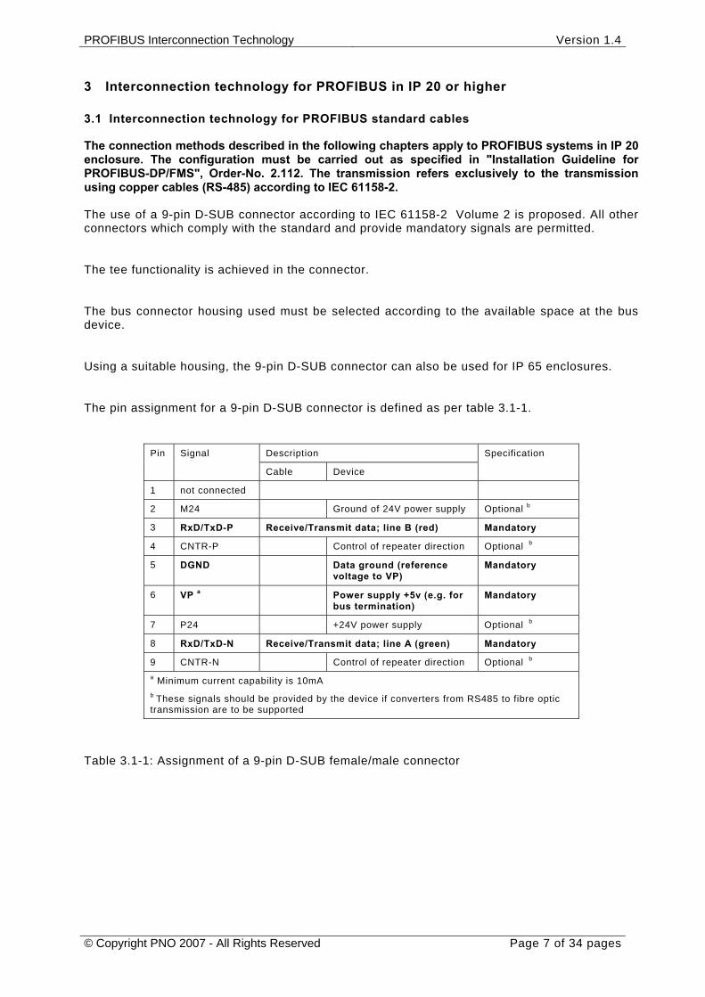
The pin assignment for a 9-pin D-SUB connector is defined as per table 3.1-1.
Table 3.1-1: Assignment of a 9-pin D-SUB female/male connector
Description Pin Signal
Cable Device
Specification
1 not connected
2 M24 Ground of 24V power supply Optional b
3 RxD/TxD-P Receive/Transmit data; line B (red) Mandatory
4 CNTR-P Control of repeater direction Optional b
5 DGND Data ground (reference voltage to VP)
Mandatory
6 VP a Power supply +5v (e.g. for bus termination)
Mandatory
7 P24 +24V power supply Optional b
8 RxD/TxD-N Receive/Transmit data; line A (green) Mandatory
9 CNTR-N Control of repeater direction Optional b a Minimum current capability is 10mA b These signals should be provided by the device if converters from RS485 to fibre optic transmission are to be supported
PROFIBUS Interconnection Technology Version 1.4
© Copyright PNO 2007 - All Rights Reserved Page 8 of 34 pages
The shield potential shall be transmitted via the metal shroud of the D-SUB connector over a large surface. Existing PROFIBUS devices with connected Pin 1 are still conform to the PROFIBUS Guideline. For new devices the Pin 1 shall not be used.
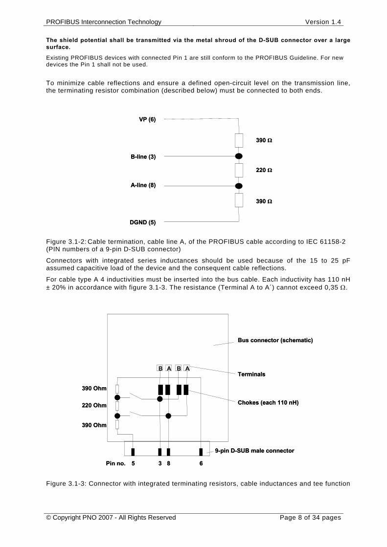
To minimize cable reflections and ensure a defined open-circuit level on the transmission line, the terminating resistor combination (described below) must be connected to both ends.
Figure 3.1-2: Cable termination, cable line A, of the PROFIBUS cable according to IEC 61158-2 (PIN numbers of a 9-pin D-SUB connector)
Connectors with integrated series inductances should be used because of the 15 to 25 pF assumed capacitive load of the device and the consequent cable reflections.
For cable type A 4 inductivities must be inserted into the bus cable. Each inductivity has 110 nH ± 20% in accordance with figure 3.1-3. The resistance (Terminal A to A´) cannot exceed 0,35 Ω.
Figure 3.1-3: Connector with integrated terminating resistors, cable inductances and tee function
390 Ω
220 Ω
VP (6)
B-line (3)
A-line (8)
DGND (5)
390 Ω
390 Ω
220 Ω
VP (6)
B-line (3)
A-line (8)
DGND (5)
390 Ω
390 Ohm
220 Ohm
390 Ohm
AA BB
Pin no. 5 3 8 6
9-pin D-SUB male connector
Chokes (each 110 nH)
Terminals
Bus connector (schematic)
390 Ohm
220 Ohm
390 Ohm
AA BB
Pin no. 5 3 8 6
9-pin D-SUB male connector
Chokes (each 110 nH)
Terminals
Bus connector (schematic)
PROFIBUS Interconnection Technology Version 1.4
© Copyright PNO 2007 - All Rights Reserved Page 9 of 34 pages
3.2 Interconnection technology for optical fibers The following connectors are used for optical PROFIBUS networks according to the PROFIBUS guideline “Fiber Optical Data Transfer for PROFIBUS”.
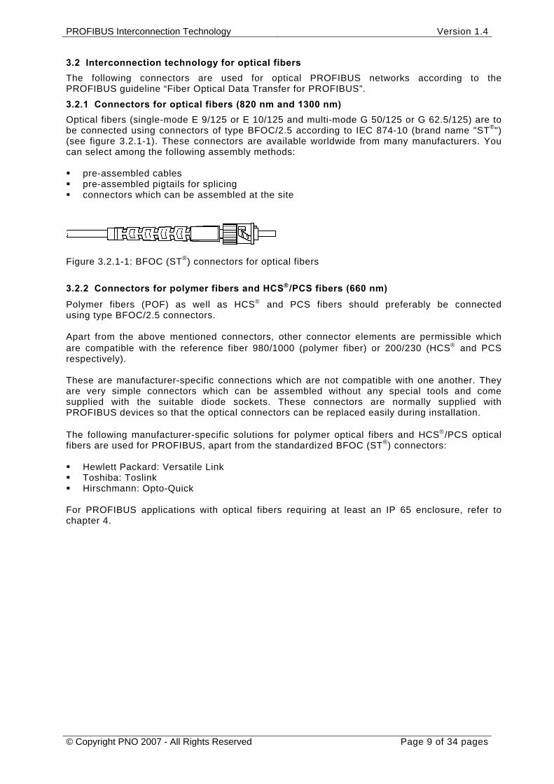
3.2.1 Connectors for optical fibers (820 nm and 1300 nm) Optical fibers (single-mode E 9/125 or E 10/125 and multi-mode G 50/125 or G 62.5/125) are to be connected using connectors of type BFOC/2.5 according to IEC 874-10 (brand name "ST®") (see figure 3.2.1-1). These connectors are available worldwide from many manufacturers. You can select among the following assembly methods: pre-assembled cables pre-assembled pigtails for splicing connectors which can be assembled at the site
Figure 3.2.1-1: BFOC (ST®) connectors for optical fibers
3.2.2 Connectors for polymer fibers and HCS®/PCS fibers (660 nm) Polymer fibers (POF) as well as HCS® and PCS fibers should preferably be connected using type BFOC/2.5 connectors. Apart from the above mentioned connectors, other connector elements are permissible which are compatible with the reference fiber 980/1000 (polymer fiber) or 200/230 (HCS® and PCS respectively). These are manufacturer-specific connections which are not compatible with one another. They are very simple connectors which can be assembled without any special tools and come supplied with the suitable diode sockets. These connectors are normally supplied with PROFIBUS devices so that the optical connectors can be replaced easily during installation. The following manufacturer-specific solutions for polymer optical fibers and HCS®/PCS optical fibers are used for PROFIBUS, apart from the standardized BFOC (ST®) connectors: Hewlett Packard: Versatile Link Toshiba: Toslink Hirschmann: Opto-Quick
For PROFIBUS applications with optical fibers requiring at least an IP 65 enclosure, refer to chapter 4.
PROFIBUS Interconnection Technology Version 1.4
© Copyright PNO 2007 - All Rights Reserved Page 10 of 34 pages
4 Interconnection technology for IP 65 or higher
4.1 Interconnection technology for PROFIBUS standard cables (RS-485)
This chapter describes the PROFIBUS Interconnection technology for applications with RS- 485 transmission technology in IP 65 or higher, which provides a power supply and bus signal via separate cables and which should have compact connectors. 4.1.1 M12 bus connector
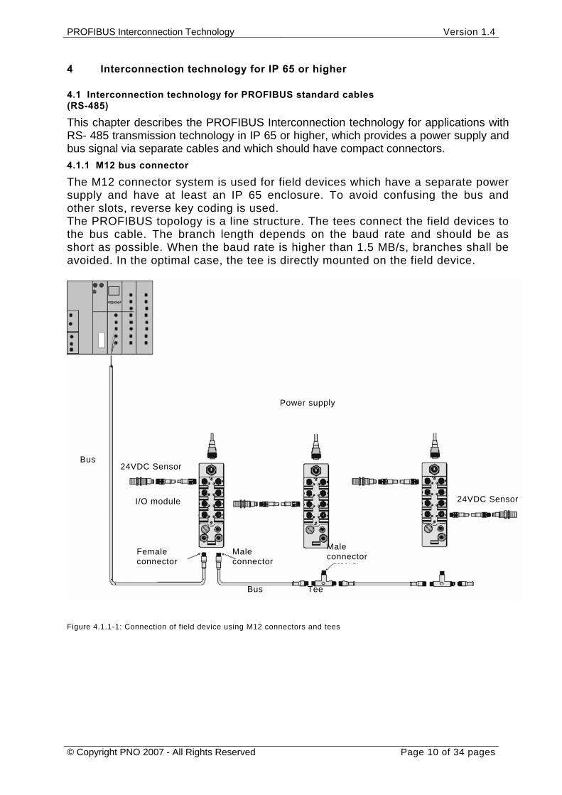
The M12 connector system is used for field devices which have a separate power supply and have at least an IP 65 enclosure. To avoid confusing the bus and other slots, reverse key coding is used. The PROFIBUS topology is a line structure. The tees connect the field devices to the bus cable. The branch length depends on the baud rate and should be as short as possible. When the baud rate is higher than 1.5 MB/s, branches shall be avoided. In the optimal case, the tee is directly mounted on the field device.
Figure 4.1.1-1: Connection of field device using M12 connectors and tees
Bus
Bus
Male connector
Female connector
Power supply
I/O module
24VDC Sensor
Tee
Male connector
24VDC Sensor
PROFIBUS Interconnection Technology Version 1.4
© Copyright PNO 2007 - All Rights Reserved Page 11 of 34 pages
If no external tees are used, two M12 connectors are required at the field device (male and female).
The terminating resistor can be integrated in the M12 connector. It can be connected directly to the tee or the field device. It is supplied via pin 1 and 3 of the M12 connector (female connector at the device). Alternatively, it can be integrated into the device and is connected when required.
4.1.2 Connector and tee structure
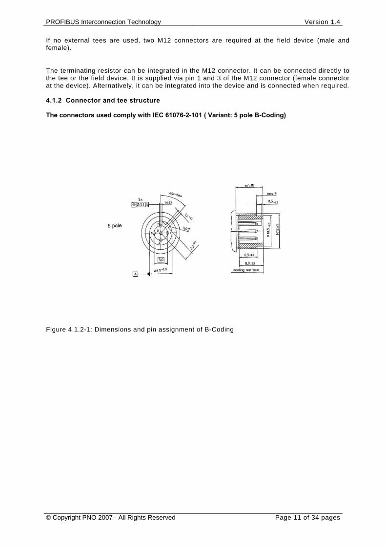
The connectors used comply with IEC 61076-2-101 ( Variant: 5 pole B-Coding)
Figure 4.1.2-1: Dimensions and pin assignment of B-Coding
PROFIBUS Interconnection Technology Version 1.4
© Copyright PNO 2007 - All Rights Reserved Page 12 of 34 pages
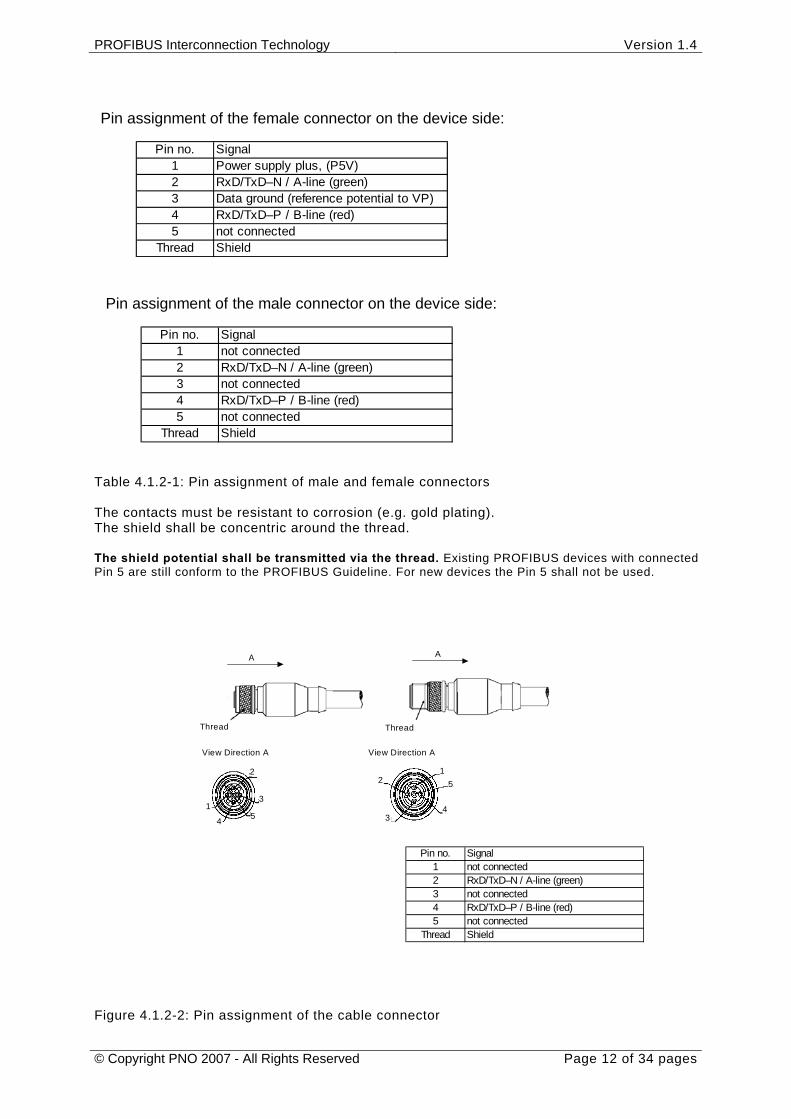
Pin assignment of the female connector on the device side:
Pin no. Signal1 Power supply plus, (P5V)2 RxD/TxD–N / A-line (green)3 Data ground (reference potential to VP)4 RxD/TxD–P / B-line (red)5 not connected
Thread Shield
Pin assignment of the male connector on the device side:
Pin no. Signal1 not connected2 RxD/TxD–N / A-line (green)3 not connected4 RxD/TxD–P / B-line (red)5 not connected
Thread Shield
Table 4.1.2-1: Pin assignment of male and female connectors The contacts must be resistant to corrosion (e.g. gold plating). The shield shall be concentric around the thread. The shield potential shall be transmitted via the thread. Existing PROFIBUS devices with connected Pin 5 are still conform to the PROFIBUS Guideline. For new devices the Pin 5 shall not be used.
A
Thread
View Direction A
1
2
3
4 5
Pin no. Signal1 not connected2 RxD/TxD–N / A-line (green)3 not connected4 RxD/TxD–P / B-line (red)5 not connected
Thread Shield
A
Thread
12
34
5
View Direction A
Figure 4.1.2-2: Pin assignment of the cable connector
PROFIBUS Interconnection Technology Version 1.4
© Copyright PNO 2007 - All Rights Reserved Page 13 of 34 pages
Existing pre harnessed PROFIBUS cable with connected Pin 5 are still conform to the PROFIBUS Guideline. For new cables the Pin 5 shall not be connected.
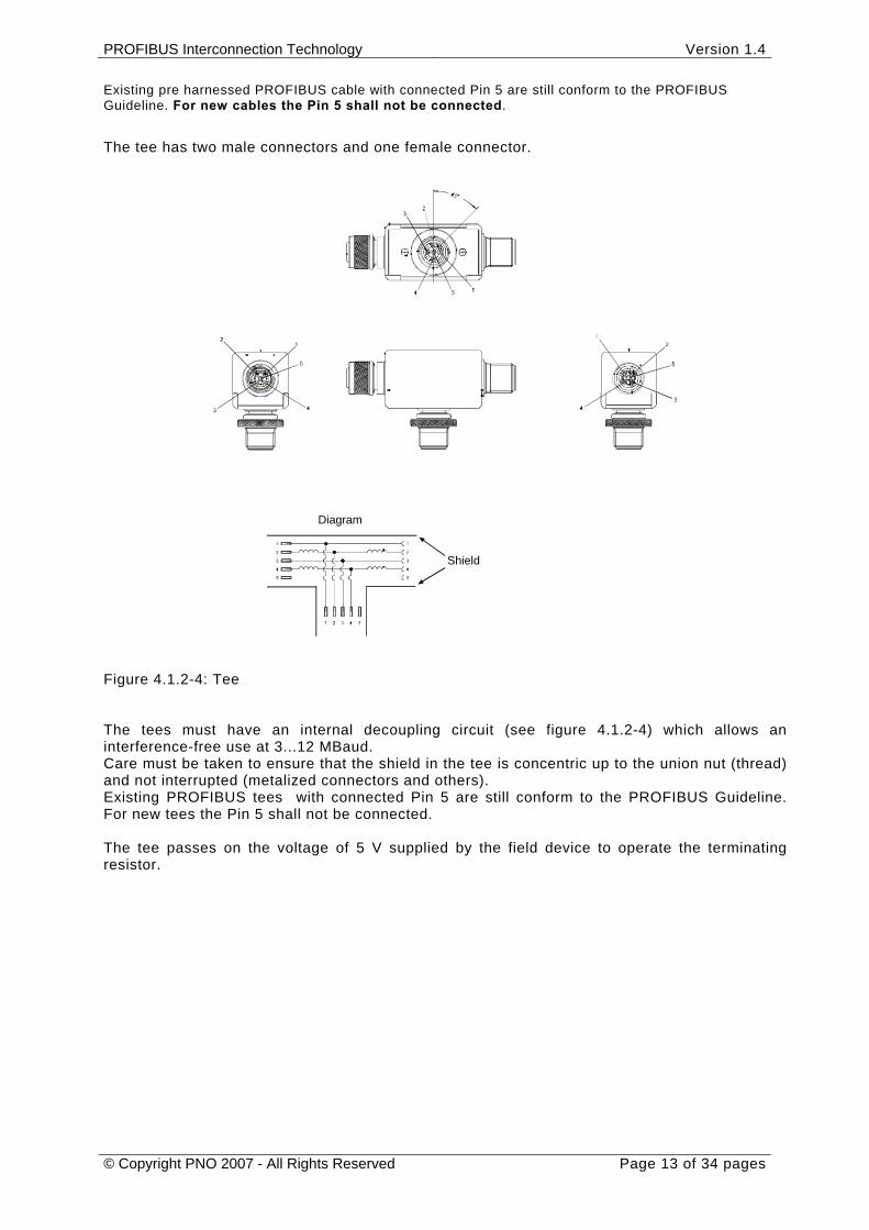
The tee has two male connectors and one female connector.
Diagram
Shield
Figure 4.1.2-4: Tee The tees must have an internal decoupling circuit (see figure 4.1.2-4) which allows an interference-free use at 3...12 MBaud. Care must be taken to ensure that the shield in the tee is concentric up to the union nut (thread) and not interrupted (metalized connectors and others). Existing PROFIBUS tees with connected Pin 5 are still conform to the PROFIBUS Guideline. For new tees the Pin 5 shall not be connected. The tee passes on the voltage of 5 V supplied by the field device to operate the terminating resistor.
PROFIBUS Interconnection Technology Version 1.4
© Copyright PNO 2007 - All Rights Reserved Page 14 of 34 pages
Diagram
Shield
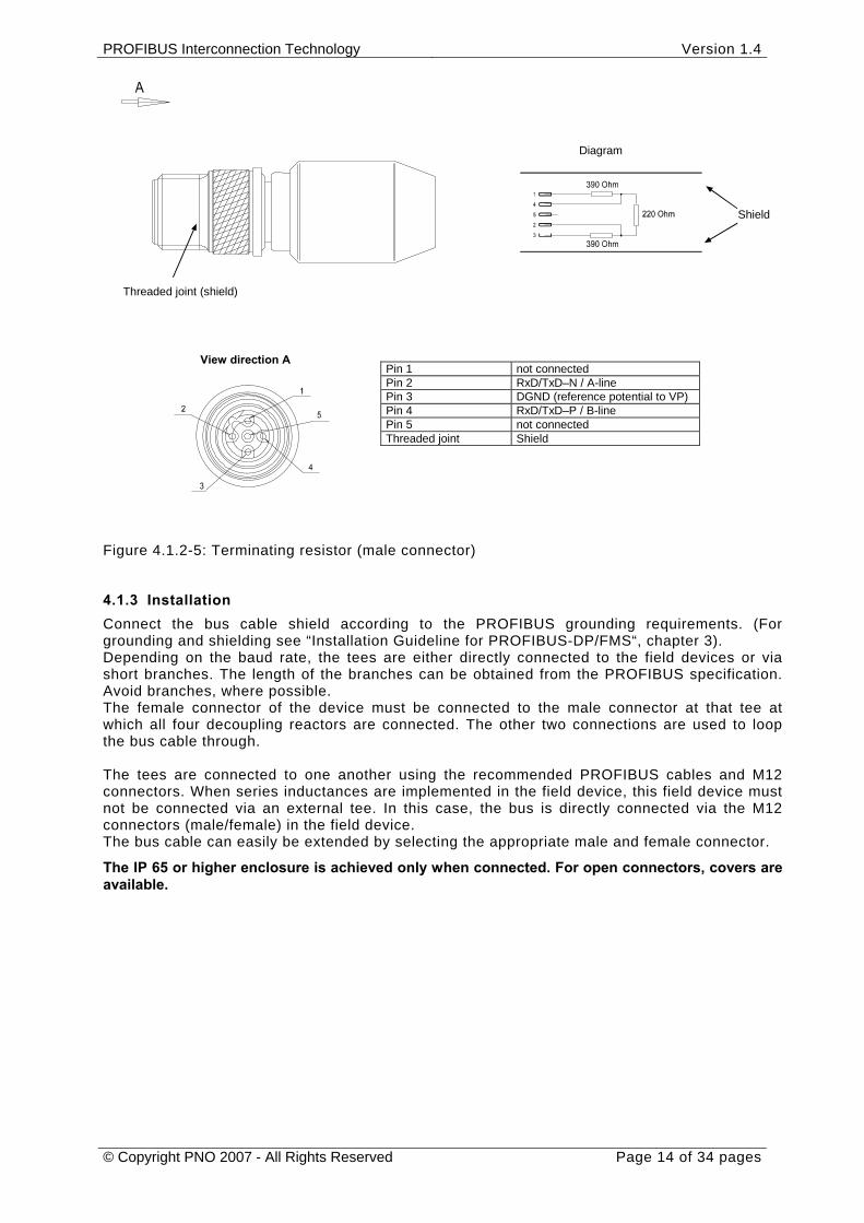
Pin 1 not connected Pin 2 RxD/TxD–N / A-line Pin 3 DGND (reference potential to VP) Pin 4 RxD/TxD–P / B-line Pin 5 not connected Threaded joint Shield
Threaded joint (shield)
View direction A
Figure 4.1.2-5: Terminating resistor (male connector)
4.1.3 Installation Connect the bus cable shield according to the PROFIBUS grounding requirements. (For grounding and shielding see “Installation Guideline for PROFIBUS-DP/FMS“, chapter 3). Depending on the baud rate, the tees are either directly connected to the field devices or via short branches. The length of the branches can be obtained from the PROFIBUS specification. Avoid branches, where possible. The female connector of the device must be connected to the male connector at that tee at which all four decoupling reactors are connected. The other two connections are used to loop the bus cable through. The tees are connected to one another using the recommended PROFIBUS cables and M12 connectors. When series inductances are implemented in the field device, this field device must not be connected via an external tee. In this case, the bus is directly connected via the M12 connectors (male/female) in the field device. The bus cable can easily be extended by selecting the appropriate male and female connector.
The IP 65 or higher enclosure is achieved only when connected. For open connectors, covers are available.

PROFIBUS Interconnection Technology Version 1.4
© Copyright PNO 2007 - All Rights Reserved Page 15 of 34 pages
4.2 Interconnection technology for standard PROFIBUS hybrid cable (RS-485)
Devices and modules for decentralized use in machines and systems are not only connected to PROFIBUS, but also to a 24-Volt power supply. Connectors require a rugged design which is suited for industrial ambient conditions. The installation system meeting these requirements consists of the following parts: Standard hybrid cable with copper wires and POF (Polymer Optical Fibers) or shielded two-
wire cable for the power supply and data transmission of field bus signals Hybrid connectors for the above mentioned cable with IP 65 enclosure or higher PROFIBUS devices with active, hybrid interfaces.
Figure 4.2-1: Illustration of the hybrid connector
4.2.1 Description of the hybrid connector family Basic features: Connection of up to four copper wires for the power supply and one contact cavity for optionally fitting a PE conductor with a cross-section of 1.5 mm² max. Simple connection Tightness for the use in rugged industrial environment with IP 65 enclosure and higher Insensitivity to electromagnetic interference
For the data lines, two versions are available: Optical fibers for data transmission. POF and HCS® can be used as copper – optical fiber hybrid cables. The optical data transmission ensures optimal electromagnetic compatibility. Large networks with a high baud rate can also be achieved. Two-wire cable for data transmission. A shielded two-wire cable according to PROFIBUS specification can be used as copper – copper hybrid cable. A module for the electrical bus connection is available which includes the shield connection and the large-surface shield transmission as well as the required inductances. The screen is connected using a clip and must be installed according to the PROFIBUS shielding requirements (see Installation Guideline for PROFIBUS-FMS/DP”, chapter 3). Independently of the data transmission medium used, the same connector housings are used so that a universal design for all cable types is possible.
Power supply
Data lines
PROFIBUS Interconnection Technology Version 1.4
© Copyright PNO 2007 - All Rights Reserved Page 16 of 34 pages
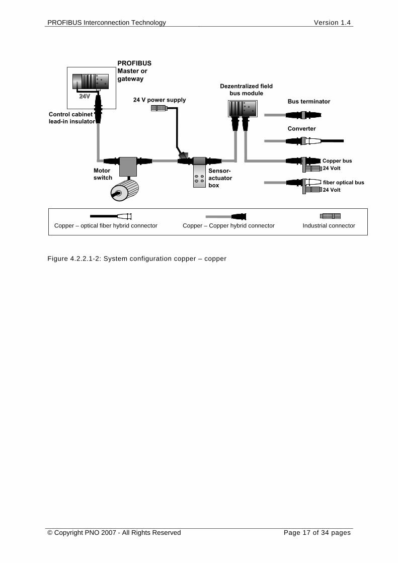
4.2.2 Description of the system configuration An installation system must offer solutions for all connectors which may be implemented. Transitions into other installation environments such as circular connectors or D-SUB connectors are supported. We can differentiate between the purely electrical installation system (copper – copper hybrid cable or copper bus cable + 24 V power supply) and the optical/electrical solution (copper – optical fiber hybrid cable or optical fiber cable + 24 V power supply). Two versions of the hybrid connector are available.
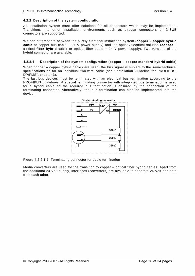
4.2.2.1 Description of the system configuration (copper – copper standard hybrid cable) When copper – copper hybrid cables are used, the bus signal is subject to the same technical specifications as for an individual two-wire cable (see "Installation Guideline for PROFIBUS-DP/FMS", chapter 3). The last bus devices must be terminated with an electrical bus termination according to the PROFIBUS guidelines. A special terminating connector with integrated bus termination is used for a hybrid cable so the required bus termination is ensured by the connection of the terminating connector. Alternatively, the bus termination can also be implemented into the device.
Bus terminating connector
B
A
4
3
2 0V
1 24V
DGND
390 Ω
5V
24V VP
390 Ω
220 Ω
Figure 4.2.2.1-1: Terminating connector for cable termination Media converters are used for the transition to copper – optical fiber hybrid cables. Apart from the additional 24 Volt supply, interfaces (converters) are available to separate 24 Volt and data from each other.
PROFIBUS Interconnection Technology Version 1.4
© Copyright PNO 2007 - All Rights Reserved Page 17 of 34 pages
24 V power supply
Dezentralized field bus module
Converter
Control cabinet lead-in insulator
24V 24V
Sensor-actuatorbox
Motor switch
Bus terminator
Copper – optical fiber hybrid connector Copper – Copper hybrid connector Industrial connector
fiber optical bus
24 VoltCopper bus
24 Volt
PROFIBUS Master or gateway
Figure 4.2.2.1-2: System configuration copper – copper
PROFIBUS Interconnection Technology Version 1.4
© Copyright PNO 2007 - All Rights Reserved Page 18 of 34 pages
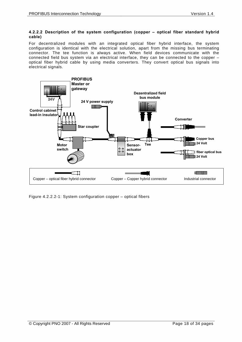
4.2.2.2 Description of the system configuration (copper – optical fiber standard hybrid cable) For decentralized modules with an integrated optical fiber hybrid interface, the system configuration is identical with the electrical solution, apart from the missing bus terminating connector. The tee function is always active. When field devices communicate with the connected field bus system via an electrical interface, they can be connected to the copper – optical fiber hybrid cable by using media converters. They convert optical bus signals into electrical signals.
Tee
24V 24V
Star coupler
24 V power supply
Dezentralized field bus module
Converter
Control cabinet lead-in insulator
Sensor-actuatorbox
Motor switch
Copper – optical fiber hybrid connector Copper – Copper hybrid connector Industrial connector
fiber optical bus
24 VoltCopper bus
24 Volt
PROFIBUS Master or gateway
Figure 4.2.2.2-1: System configuration copper – optical fibers
PROFIBUS Interconnection Technology Version 1.4
© Copyright PNO 2007 - All Rights Reserved Page 19 of 34 pages
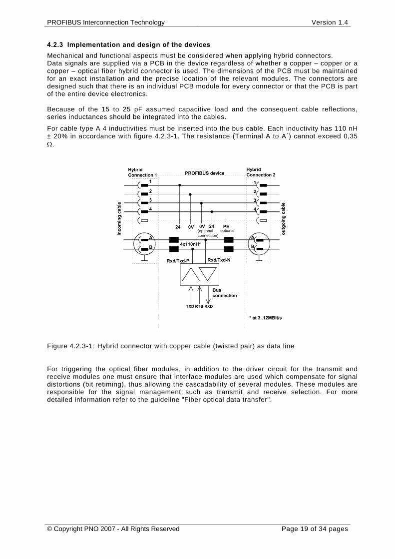
4.2.3 Implementation and design of the devices Mechanical and functional aspects must be considered when applying hybrid connectors. Data signals are supplied via a PCB in the device regardless of whether a copper – copper or a copper – optical fiber hybrid connector is used. The dimensions of the PCB must be maintained for an exact installation and the precise location of the relevant modules. The connectors are designed such that there is an individual PCB module for every connector or that the PCB is part of the entire device electronics. Because of the 15 to 25 pF assumed capacitive load and the consequent cable reflections, series inductances should be integrated into the cables.
For cable type A 4 inductivities must be inserted into the bus cable. Each inductivity has 110 nH ± 20% in accordance with figure 4.2.3-1. The resistance (Terminal A to A´) cannot exceed 0,35 Ω.
PROFIBUS device
RTSTXD
Rxd/Txd-P
Inco
min
g ca
ble
4
A B 4x110nH*
24 0V
3 2 1
Hybrid Connection 1
* at 3..12MBit/s RXD
Bus connection
Rxd/Txd-N
4
PEoptional (optional
connection)
0V 24
A
B
3
2
1
HybridConnection 2
outg
oing
cab
le
Figure 4.2.3-1: Hybrid connector with copper cable (twisted pair) as data line For triggering the optical fiber modules, in addition to the driver circuit for the transmit and receive modules one must ensure that interface modules are used which compensate for signal distortions (bit retiming), thus allowing the cascadability of several modules. These modules are responsible for the signal management such as transmit and receive selection. For more detailed information refer to the guideline "Fiber optical data transfer".
PROFIBUS Interconnection Technology Version 1.4
© Copyright PNO 2007 - All Rights Reserved Page 20 of 34 pages
- Retiming- Signal management
E 2xLWL
RTS
E O E
(5)xCu 4
O S
0V24V
3 2 1
O
S
TXD RXD
EO
2xLWL
E
4
PE0V 24V
E
3
2
1
4(5)xCu
PROFIBUS device
Inco
min
g ca
ble
Hybrid Connection 1
optional (optional connection)
HybridConnection 2
outg
oing
cab
le
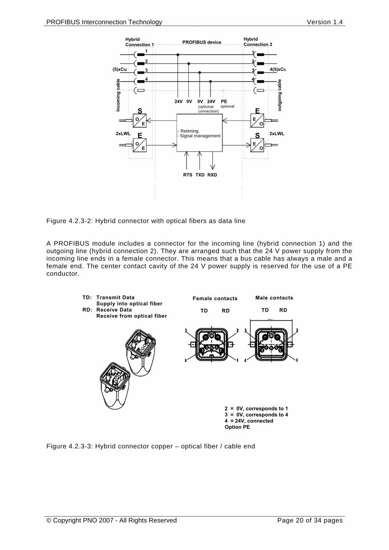
Figure 4.2.3-2: Hybrid connector with optical fibers as data line A PROFIBUS module includes a connector for the incoming line (hybrid connection 1) and the outgoing line (hybrid connection 2). They are arranged such that the 24 V power supply from the incoming line ends in a female connector. This means that a bus cable has always a male and a female end. The center contact cavity of the 24 V power supply is reserved for the use of a PE conductor.
Figure 4.2.3-3: Hybrid connector copper – optical fiber / cable end
TD: Transmit Data Supply into optical fiber
RD: Receive Data Receive from optical fiber
Female contacts
TD RD
Male contacts
TD RD
2 = 0V, corresponds to 1 3 = 0V, corresponds to 4 4 = 24V, connected Option PE
PROFIBUS Interconnection Technology Version 1.4
© Copyright PNO 2007 - All Rights Reserved Page 21 of 34 pages
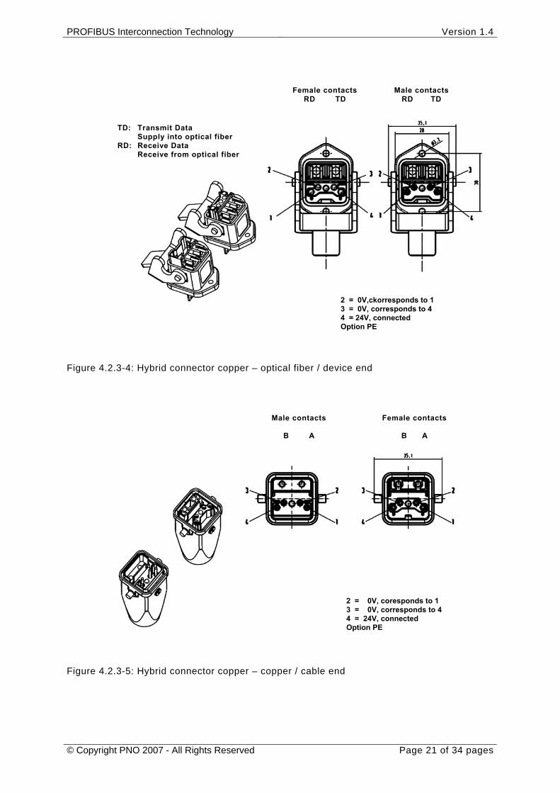
Figure 4.2.3-4: Hybrid connector copper – optical fiber / device end
Figure 4.2.3-5: Hybrid connector copper – copper / cable end
Male contacts
B A
Female contacts
B A
2 = 0V, coresponds to 1 3 = 0V, corresponds to 4 4 = 24V, connected Option PE
TD: Transmit Data Supply into optical fiber
RD: Receive Data Receive from optical fiber
Female contacts RD TD
Male contacts RD TD
2 = 0V,ckorresponds to 1 3 = 0V, corresponds to 4 4 = 24V, connected Option PE
PROFIBUS Interconnection Technology Version 1.4
© Copyright PNO 2007 - All Rights Reserved Page 22 of 34 pages
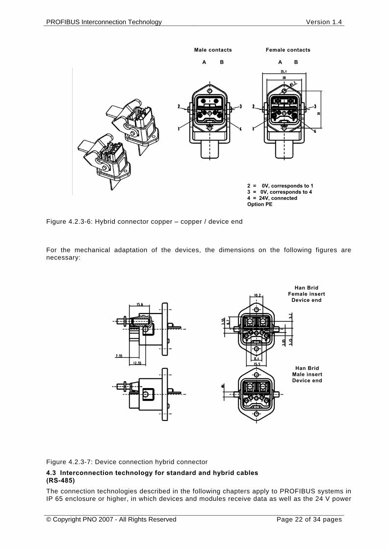
Figure 4.2.3-6: Hybrid connector copper – copper / device end For the mechanical adaptation of the devices, the dimensions on the following figures are necessary:
Figure 4.2.3-7: Device connection hybrid connector 4.3 Interconnection technology for standard and hybrid cables (RS-485) The connection technologies described in the following chapters apply to PROFIBUS systems in IP 65 enclosure or higher, in which devices and modules receive data as well as the 24 V power
Male contacts
A B
Female contacts
A B
2 = 0V, corresponds to 1 3 = 0V, corresponds to 4 4 = 24V, connected Option PE
Han Brid Female insert
Device end
Han Brid Male insert Device end
PROFIBUS Interconnection Technology Version 1.4
© Copyright PNO 2007 - All Rights Reserved Page 23 of 34 pages
supply for electronics and encoder via a connector, and a hybrid cable or separate cables as option. The transmission exclusively refers to the transmission via copper cable (RS-485) in accordance with IEC 61158-2 .
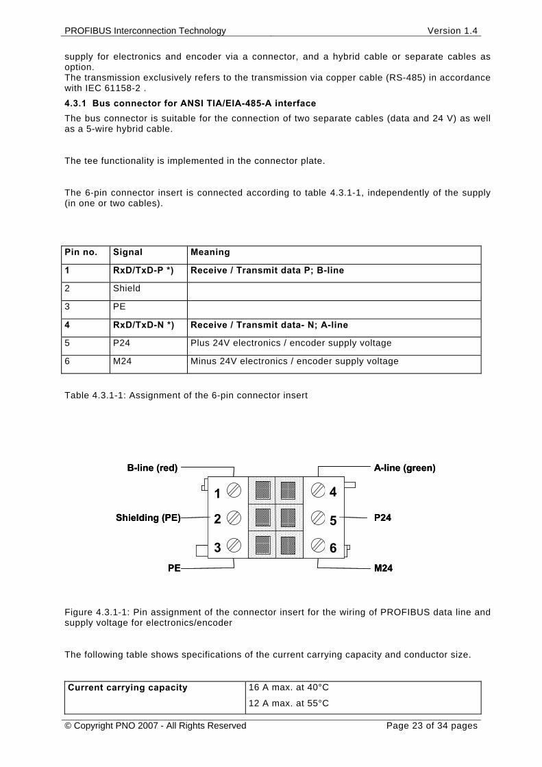
4.3.1 Bus connector for ANSI TIA/EIA-485-A interface The bus connector is suitable for the connection of two separate cables (data and 24 V) as well as a 5-wire hybrid cable.
The tee functionality is implemented in the connector plate.
The 6-pin connector insert is connected according to table 4.3.1-1, independently of the supply (in one or two cables).
Pin no. Signal Meaning
1 RxD/TxD-P *) Receive / Transmit data P; B-line
2 Shield
3 PE
4 RxD/TxD-N *) Receive / Transmit data- N; A-line
5 P24 Plus 24V electronics / encoder supply voltage
6 M24 Minus 24V electronics / encoder supply voltage
Table 4.3.1-1: Assignment of the 6-pin connector insert
Figure 4.3.1-1: Pin assignment of the connector insert for the wiring of PROFIBUS data line and supply voltage for electronics/encoder
The following table shows specifications of the current carrying capacity and conductor size.
Current carrying capacity 16 A max. at 40°C
12 A max. at 55°C
B-line (red) A-line (green)
Shielding (PE)
PE M24
P24
1
2
3
4
5
6
B-line (red) A-line (green)
Shielding (PE)
PE M24
P24
1
2
3
4
5
6
PROFIBUS Interconnection Technology Version 1.4
© Copyright PNO 2007 - All Rights Reserved Page 24 of 34 pages
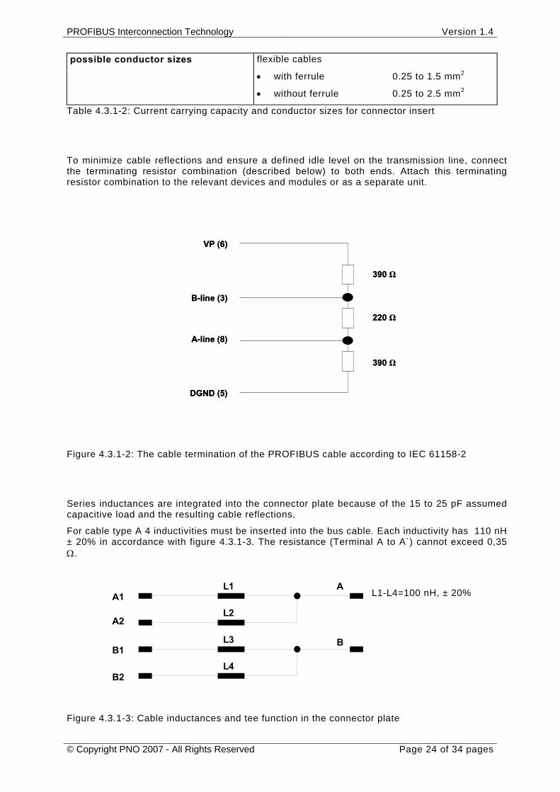
possible conductor sizes flexible cables
• with ferrule 0.25 to 1.5 mm2
• without ferrule 0.25 to 2.5 mm2
Table 4.3.1-2: Current carrying capacity and conductor sizes for connector insert
To minimize cable reflections and ensure a defined idle level on the transmission line, connect the terminating resistor combination (described below) to both ends. Attach this terminating resistor combination to the relevant devices and modules or as a separate unit.
Figure 4.3.1-2: The cable termination of the PROFIBUS cable according to IEC 61158-2
Series inductances are integrated into the connector plate because of the 15 to 25 pF assumed capacitive load and the resulting cable reflections.
For cable type A 4 inductivities must be inserted into the bus cable. Each inductivity has 110 nH ± 20% in accordance with figure 4.3.1-3. The resistance (Terminal A to A´) cannot exceed 0,35 Ω.
Figure 4.3.1-3: Cable inductances and tee function in the connector plate
390 Ω
220 Ω
VP (6)
B-line (3)
A-line (8)
DGND (5)
390 Ω
390 Ω
220 Ω
VP (6)
B-line (3)
A-line (8)
DGND (5)
390 Ω
L1
L2
L3
L4
A1
B1
A2
B2
A
B
L1-L4=100nHL1-L4=100 nH, ± 20%
PROFIBUS Interconnection Technology Version 1.4
© Copyright PNO 2007 - All Rights Reserved Page 25 of 34 pages
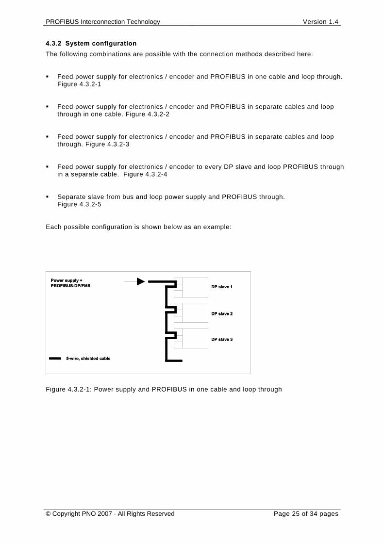
4.3.2 System configuration The following combinations are possible with the connection methods described here:
Feed power supply for electronics / encoder and PROFIBUS in one cable and loop through. Figure 4.3.2-1
Feed power supply for electronics / encoder and PROFIBUS in separate cables and loop through in one cable. Figure 4.3.2-2
Feed power supply for electronics / encoder and PROFIBUS in separate cables and loop through. Figure 4.3.2-3
Feed power supply for electronics / encoder to every DP slave and loop PROFIBUS through in a separate cable. Figure 4.3.2-4
Separate slave from bus and loop power supply and PROFIBUS through. Figure 4.3.2-5
Each possible configuration is shown below as an example:
Figure 4.3.2-1: Power supply and PROFIBUS in one cable and loop through
5-wire, shielded cable
DP slave 1
DP slave 2
DP slave 3
Power supply +PROFIBUS-DP/FMS
5-wire, shielded cable
DP slave 1
DP slave 2
DP slave 3
Power supply +PROFIBUS-DP/FMS
PROFIBUS Interconnection Technology Version 1.4
© Copyright PNO 2007 - All Rights Reserved Page 26 of 34 pages
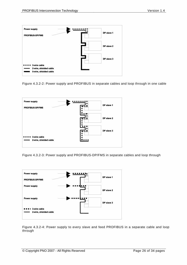
Figure 4.3.2-2: Power supply and PROFIBUS in separate cables and loop through in one cable
Figure 4.3.2-3: Power supply and PROFIBUS-DP/FMS in separate cables and loop through
Figure 4.3.2-4: Power supply to every slave and feed PROFIBUS in a separate cable and loop through
Power supply
PROFIBUS-DP/FMS
3-wire cable2-wire, shielded cable
DP slave 1
DP slave 2
DP slave 3
5-wire, shielded cable
Power supply
PROFIBUS-DP/FMS
3-wire cable2-wire, shielded cable
DP slave 1
DP slave 2
DP slave 3
5-wire, shielded cable
Power supply
PROFIBUS-DP/FMS
3-wire cable2-wire, shielded cable
DP slave 1
DP slave 2
DP slave 3
Power supply
PROFIBUS-DP/FMS
3-wire cable2-wire, shielded cable
DP slave 1
DP slave 2
DP slave 3
PROFIBUS-DP/FMS
3-wire cable2-wire, shielded cable
DP slave 1
DP slave 2
DP slave 3
Power supply
Power supply
Power supply
PROFIBUS-DP/FMS
3-wire cable2-wire, shielded cable
DP slave 1
DP slave 2
DP slave 3
Power supply
Power supply
Power supply
PROFIBUS Interconnection Technology Version 1.4
© Copyright PNO 2007 - All Rights Reserved Page 27 of 34 pages
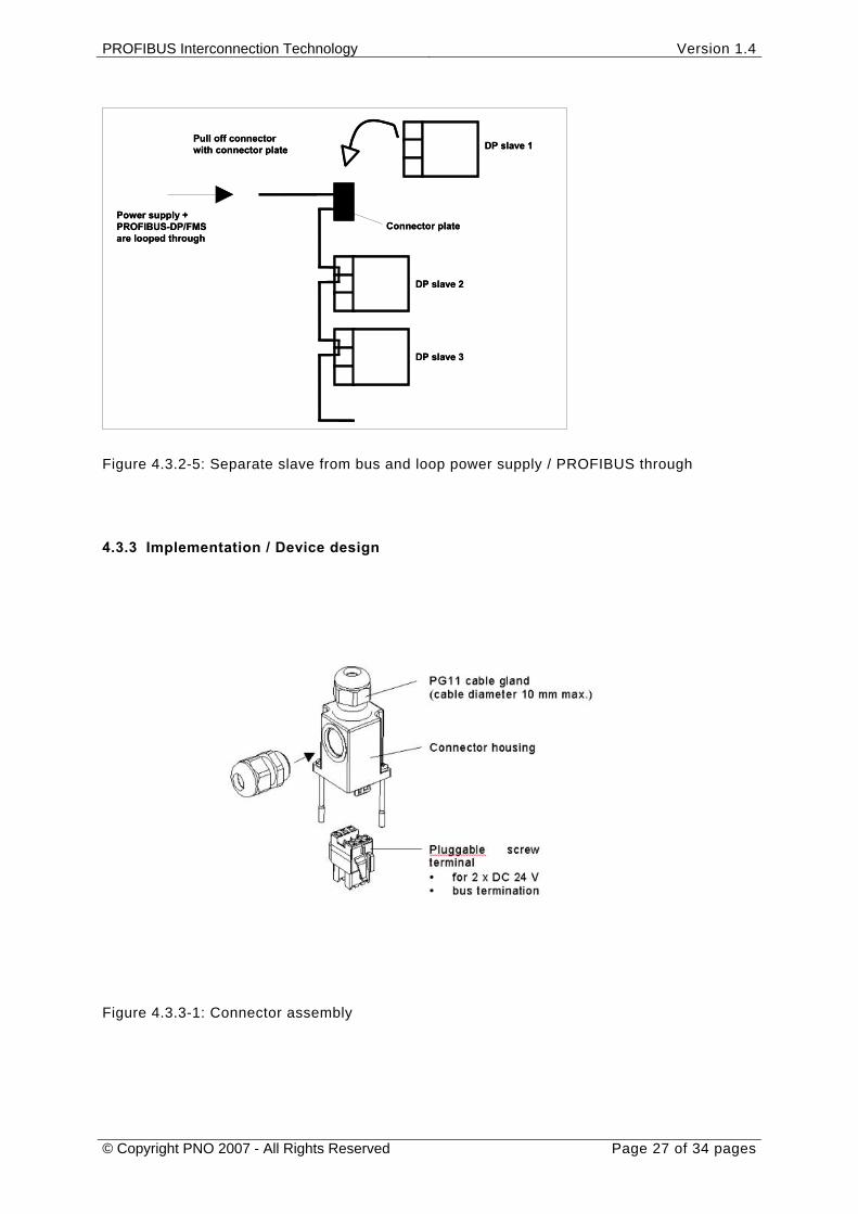
Figure 4.3.2-5: Separate slave from bus and loop power supply / PROFIBUS through
4.3.3 Implementation / Device design
Figure 4.3.3-1: Connector assembly
DP slave 1
DP slave 2
DP slave 3
Connector plate
Pull off connectorwith connector plate
Power supply +PROFIBUS-DP/FMSare looped through
DP slave 1
DP slave 2
DP slave 3
Connector plate
Pull off connectorwith connector plate
Power supply +PROFIBUS-DP/FMSare looped through
PROFIBUS Interconnection Technology Version 1.4
© Copyright PNO 2007 - All Rights Reserved Page 28 of 34 pages
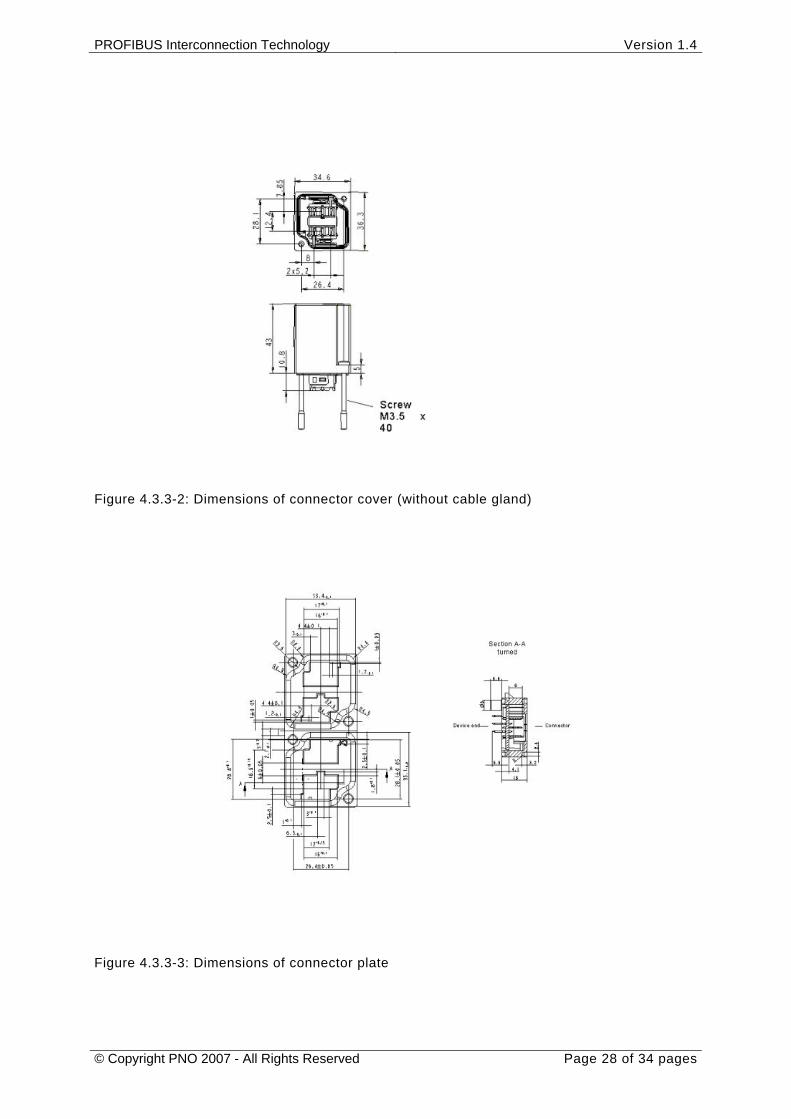
Figure 4.3.3-2: Dimensions of connector cover (without cable gland)
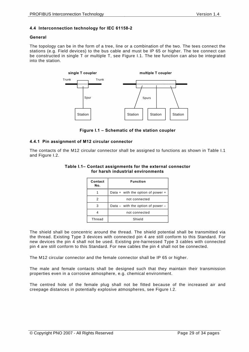
Figure 4.3.3-3: Dimensions of connector plate
PROFIBUS Interconnection Technology Version 1.4
© Copyright PNO 2007 - All Rights Reserved Page 29 of 34 pages
4.4 Interconnection technology for IEC 61158-2
General
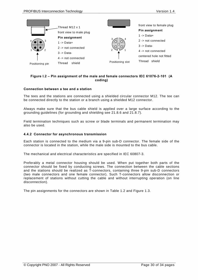
The topology can be in the form of a tree, line or a combination of the two. The tees connect the stations (e.g. Field devices) to the bus cable and must be IP 65 or higher. The tee connect can be constructed in single T or multiple T, see Figure I.1. The tee function can also be integrated into the station.
single T coupler
Station
Spur
Trunk Trunk
multiple T coupler
Spurs
Station Station Station
Figure I.1 – Schematic of the station coupler
4.4.1 Pin assignment of M12 circular connector
The contacts of the M12 circular connector shall be assigned to functions as shown in Table I.1 and Figure I.2.
Table I.1– Contact assignments for the external connector for harsh industrial environments
Contact No.
Function
1 Data + with the option of power +
2 not connected
3 Data – with the option of power –
4 not connected
Thread Shield
The shield shall be concentric around the thread. The shield potential shall be transmitted via the thread. Existing Type 3 devices with connected pin 4 are still conform to this Standard. For new devices the pin 4 shall not be used. Existing pre-harnessed Type 3 cables with connected pin 4 are still conform to this Standard. For new cables the pin 4 shall not be connected.
The M12 circular connector and the female connector shall be IP 65 or higher.
The male and female contacts shall be designed such that they maintain their transmission properties even in a corrosive atmosphere, e.g. chemical environment.
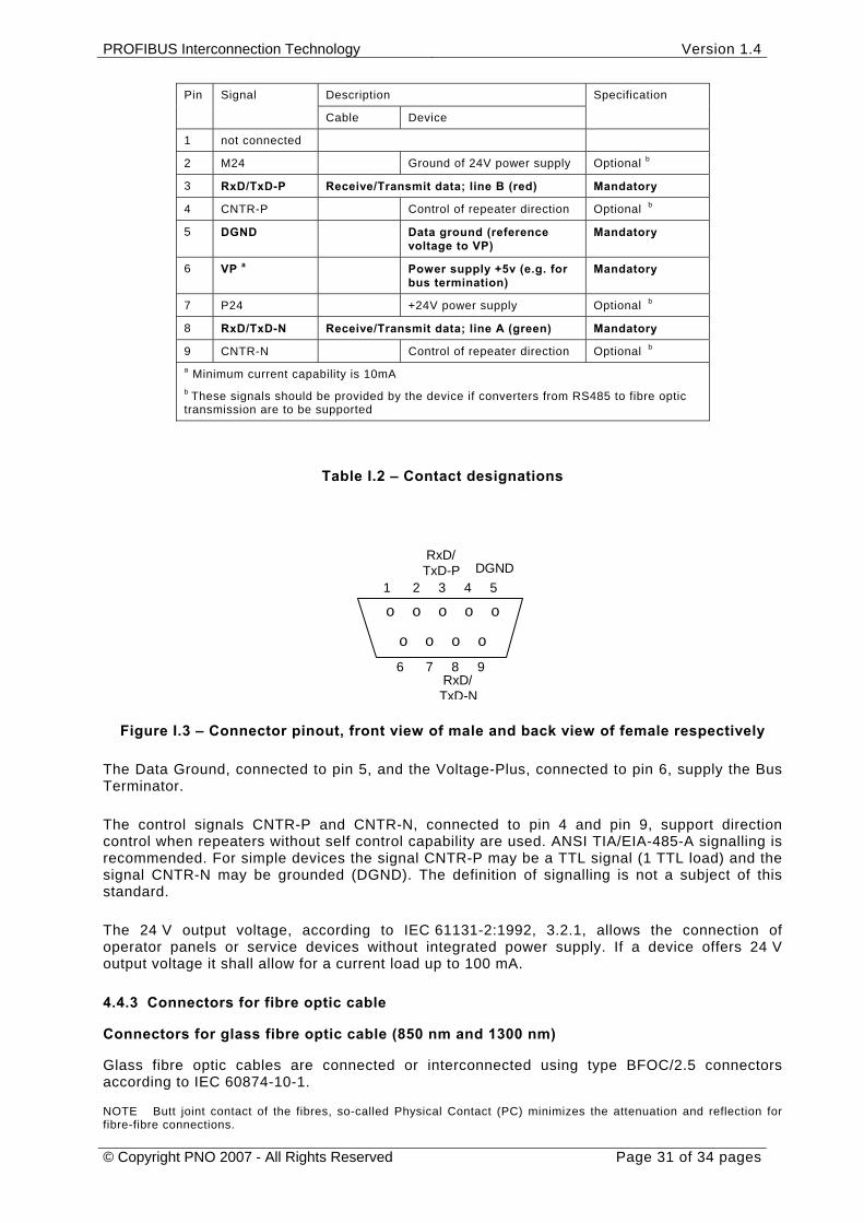
The centred hole of the female plug shall not be fitted because of the increased air and creepage distances in potentially explosive atmospheres, see Figure I.2.
PROFIBUS Interconnection Technology Version 1.4
© Copyright PNO 2007 - All Rights Reserved Page 30 of 34 pages
1
4 3
2
Positioning pinPositioning slot
Thread M12 x 1
front view to male plug
Pin assignment1 -> Data+
2 -> not connected
3 -> Data-
4 -> not connectedThread shield
front view to female plug
Pin assignment1 -> Data+
2 -> not connected
3 -> Data-
4 -> not connected
centered hole not fitted
Thread shield
2
3 4
1
Figure I.2 – Pin assignment of the male and female connectors IEC 61076-2-101 (A coding)
Connection between a tee and a station
The tees and the stations are connected using a shielded circular connector M12. The tee can be connected directly to the station or a branch using a shielded M12 connector.
Always make sure that the bus cable shield is applied over a large surface according to the grounding guidelines (for grounding and shielding see 21.8.6 and 21.8.7).
Field termination techniques such as screw or blade terminals and permanent termination may also be used.
4.4.2 Connector for asynchronous transmission
Each station is connected to the medium via a 9-pin sub-D connector. The female side of the connector is located in the station, while the male side is mounted to the bus cable.
The mechanical and electrical characteristics are specified in IEC 60807-3.
Preferably a metal connector housing should be used. When put together both parts of the connector should be fixed by conducting screws. The connection between the cable sections and the stations should be realized as T-connectors, containing three 9-pin sub-D connectors (two male connectors and one female connector). Such T-connectors allow disconnection or replacement of stations without cutting the cable and without interrupting operation (on line disconnection).
The pin assignments for the connectors are shown in Table 1.2 and Figure 1.3.
PROFIBUS Interconnection Technology Version 1.4
© Copyright PNO 2007 - All Rights Reserved Page 31 of 34 pages
Table I.2 – Contact designations
1 2 3 4 5
o o o o
oo o o o
6 7 8 9 RxD/TxD-N
RxD/TxD-P DGND
Figure I.3 – Connector pinout, front view of male and back view of female respectively
The Data Ground, connected to pin 5, and the Voltage-Plus, connected to pin 6, supply the Bus Terminator.
The control signals CNTR-P and CNTR-N, connected to pin 4 and pin 9, support direction control when repeaters without self control capability are used. ANSI TIA/EIA-485-A signalling is recommended. For simple devices the signal CNTR-P may be a TTL signal (1 TTL load) and the signal CNTR-N may be grounded (DGND). The definition of signalling is not a subject of this standard.
The 24 V output voltage, according to IEC 61131-2:1992, 3.2.1, allows the connection of operator panels or service devices without integrated power supply. If a device offers 24 V output voltage it shall allow for a current load up to 100 mA.
4.4.3 Connectors for fibre optic cable
Connectors for glass fibre optic cable (850 nm and 1300 nm)
Glass fibre optic cables are connected or interconnected using type BFOC/2.5 connectors according to IEC 60874-10-1.
NOTE Butt joint contact of the fibres, so-called Physical Contact (PC) minimizes the attenuation and reflection for fibre-fibre connections.
Description Pin Signal
Cable Device
Specification
1 not connected
2 M24 Ground of 24V power supply Optional b
3 RxD/TxD-P Receive/Transmit data; line B (red) Mandatory
4 CNTR-P Control of repeater direction Optional b
5 DGND Data ground (reference voltage to VP)
Mandatory
6 VP a Power supply +5v (e.g. for bus termination)
Mandatory
7 P24 +24V power supply Optional b
8 RxD/TxD-N Receive/Transmit data; line A (green) Mandatory
9 CNTR-N Control of repeater direction Optional b a Minimum current capability is 10mA b These signals should be provided by the device if converters from RS485 to fibre optic transmission are to be supported
PROFIBUS Interconnection Technology Version 1.4
© Copyright PNO 2007 - All Rights Reserved Page 32 of 34 pages
Connectors for plastic and glass fibre optic cable (660 nm)
Plastic fibre optic cables are preferentially connected or interconnected using type BFOC/2.5 connectors.
Other connector elements are admissible if they are compatible to reference fibre 980/1000 plastic fibre or 200/230 glass fibre.
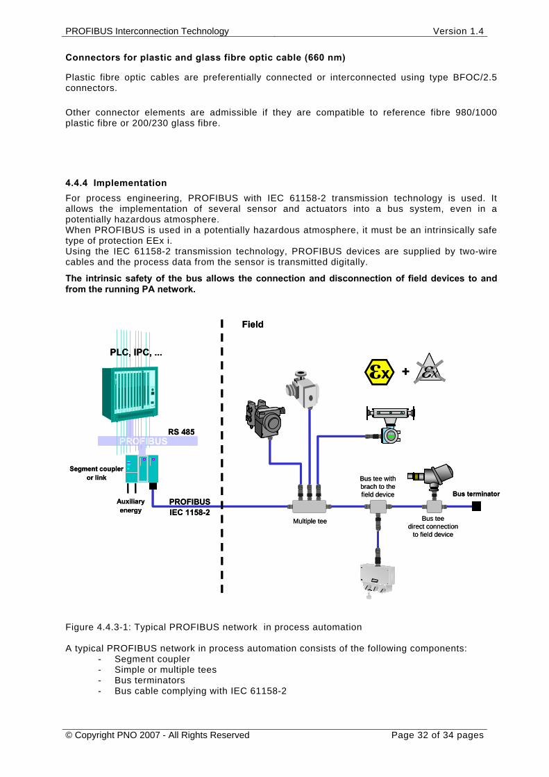
4.4.4 Implementation For process engineering, PROFIBUS with IEC 61158-2 transmission technology is used. It allows the implementation of several sensor and actuators into a bus system, even in a potentially hazardous atmosphere. When PROFIBUS is used in a potentially hazardous atmosphere, it must be an intrinsically safe type of protection EEx i. Using the IEC 61158-2 transmission technology, PROFIBUS devices are supplied by two-wire cables and the process data from the sensor is transmitted digitally.
The intrinsic safety of the bus allows the connection and disconnection of field devices to and from the running PA network.
Figure 4.4.3-1: Typical PROFIBUS network in process automation A typical PROFIBUS network in process automation consists of the following components:
- Segment coupler - Simple or multiple tees - Bus terminators - Bus cable complying with IEC 61158-2
PROFIBUSIEC 1158-2
Auxiliaryenergy
Segment coupleror link
PROFIBUS
εx+PLC, IPC, ...
RS 485
Bus terminator
Field
Bus teedirect connection
to field device
Bus tee withbrach to thefield device
Multiple tee
εx
PROFIBUSIEC 1158-2
Auxiliaryenergy
Segment coupleror link
PROFIBUS
εxεx+PLC, IPC, ...
RS 485
Bus terminator
Field
Bus teedirect connection
to field device
Bus tee withbrach to thefield device
Multiple tee
εxεx

PROFIBUS Interconnection Technology Version 1.4
© Copyright PNO 2007 - All Rights Reserved Page 33 of 34 pages
Operation in an atmosphere which is not potentially hazardous is restricted only by
- the maximum number of connected field devices - the maximum length of the bus cable - the maximum length of the branches (cables between tees and field devices)
The number of field devices, the length of the bus cable and the branches is even more restricted in a potentially hazardous atmosphere. All components (segment couplers, tees, field devices and bus terminators) must comply with the intrinsically safe type of protection EEx i. The bus termination must be visible. (see "PROFIBUS-PA User and Installation Guideline", chapter 3)

© Copyright by: PROFIBUS Nutzerorganisation e.V. Haid-und-Neu-Str. 7 76131 Karlsruhe Germany Phone: +49 (0) 721 / 96 58 590 Fax: +49 (0) 721 / 96 58 589 e-mail: [email protected] http://www.profibus.com