proficy* batch execution - kerrco one or more ifix scada servers each batch execution system...
TRANSCRIPT

Proficy* Batch Execution
A P P L I C A T I O N G U I D E
V e r s i o n 5 . 6
D e c e m b e r 2 0 1 0

All rights reserved. No part of this publication may be reproduced in any form or by any electronic or mechanical means, including photocopying and recording, without permission in writing from GE Intelligent Platforms, Inc.
Disclaimer of Warranties and Liability
The information contained in this manual is believed to be accurate and reliable. However, GE Intelligent Platforms, Inc. assumes no responsibilities for any errors, omissions or inaccuracies whatsoever. Without limiting the foregoing, GE Intelligent Platforms, Inc. disclaims any and all warranties, expressed or implied, including the warranty of merchantability and fitness for a particular purpose, with respect to the information contained in this manual and the equipment or software described herein. The entire risk as to the quality and performance of such information, equipment and software, is upon the buyer or user. GE Intelligent Platforms, Inc. shall not be liable for any damages, including special or consequential damages, arising out of the user of such information, equipment and software, even if GE Intelligent Platforms, Inc. has been advised in advance of the possibility of such damages. The user of the information contained in the manual and the software described herein is subject to the GE Intelligent Platforms, Inc. standard license agreement, which must be executed by the buyer or user before the use of such information, equipment or software.
Notice
©2010 GE Intelligent Platforms, Inc. All rights reserved. *Trademark of GE Intelligent Platforms, Inc.
Microsoft® is a registered trademark of Microsoft Corporation, in the United States and/or other countries.
All other brands or names are property of their respective holders.
We want to hear from you. If you have comments, questions, or suggestions about our documentation, send them to the following email address:

iii
Table of Contents
About This Guide .............................................................................................................................. 1
Icon Index ......................................................................................................................................... 2
Introduction to Batch Execution ........................................................................................................ 3
Batch Execution Client-Server Architecture ................................................................................. 3
Batch Execution System Components ..................................................................................... 4
Integration with iFIX ...................................................................................................................... 5
Terminal Server Support for iFIX and Batch Execution................................................................ 5
Proficy Batch Execution WorkSpace ............................................................................................ 6
VBIS .............................................................................................................................................. 7
ActiveX Controls ........................................................................................................................... 7
Manufacturing Standards Compliance ......................................................................................... 8
Designed for 21 CFR Part 11 ....................................................................................................... 8
OPC Specification......................................................................................................................... 9
Using the Batch Execution Demo Project .................................................................................... 9
Batch Execution and the ISA S88.01 Models ................................................................................... 9
The Physical Model .................................................................................................................... 10
Enterprise, Site, and Area Levels ........................................................................................... 11
Process Cell ............................................................................................................................ 12
Unit.......................................................................................................................................... 13
Equipment Modules and Control Modules ............................................................................. 14
Procedural Control Model ........................................................................................................... 15
Control Activity Model ................................................................................................................. 17
Recipe Management............................................................................................................... 17
Production Planning and Scheduling...................................................................................... 20
Process Management ............................................................................................................. 21

Application Guide
iv
Unit Supervision ...................................................................................................................... 22
Process Control ...................................................................................................................... 22
Production Information Management ..................................................................................... 22
Process Model ............................................................................................................................ 23
Linking a Control Recipe to the Equipment ............................................................................ 24
Exploring the Sample Application ................................................................................................... 24
Designing the Toothpaste Control Strategy ............................................................................... 25
Outlining the General Procedure ............................................................................................ 25
Identifying the Process Flow ................................................................................................... 25
Partitioning Plant Equipment .................................................................................................. 25
Equipment Requirements ....................................................................................................... 26
Other Samples ............................................................................................................................ 27
Developing a Batch Execution Project ........................................................................................... 27
Development Overview .............................................................................................................. 28
Reporting and Analyzing Production Data ................................................................................. 28
Active Journaling .................................................................................................................... 28
Archiving Process Values ....................................................................................................... 29
Proficy Plant Applications Batch Analysis Reports ................................................................. 30
Developing a Batch Execution WorkSpace Project .................................................................... 31
Embedding OLE Documents .................................................................................................. 32
Using the Proficy iFIX WorkSpace ......................................................................................... 32
Programming the Process Controller ......................................................................................... 33
Understanding the PLI ............................................................................................................ 33
Understanding the Phase Logic ............................................................................................. 34
Configuring the Area Model ........................................................................................................ 34
Developing Recipes .................................................................................................................... 36
Using Active Binding ............................................................................................................... 37
Using Recipe Parameters ....................................................................................................... 37

Table Of Contents
v
Using Class-Based Recipes ................................................................................................... 37
Parallel Processing ................................................................................................................. 38
Storing Recipes in the Relational Database ............................................................................... 39
Using the Batch Execution Soft Phase Server ........................................................................... 39
Developing iFIX Pictures ............................................................................................................ 40
Batch Execution Operations ........................................................................................................... 40
Operations Overview .................................................................................................................. 40
Understanding Batch Execution ................................................................................................. 41
Understanding States ............................................................................................................. 42
Controlling and Monitoring Batches............................................................................................ 43
Using the ActiveX Controls ..................................................................................................... 44
Developing VBIS Applications ................................................................................................ 45
Using the Campaign Manager ................................................................................................ 45
Using Proficy Workflow to Manage Campaigns ..................................................................... 45
Mastering Batch Execution ............................................................................................................. 46
Using Proficy Plant Applications Batch Analysis Reports .......................................................... 47
Understanding Active Binding .................................................................................................... 47
Configuring Active Binding in the Area Model ........................................................................ 48
Configuring Active Binding in Recipes.................................................................................... 48
Example: Active Binding Area Model Configuration ............................................................... 49
Example: Active Binding Recipe Configuration ...................................................................... 51
Example: Active Binding at Run Time .................................................................................... 52
Implementing a Class-Based Design ......................................................................................... 53
Example: Class-Based Design ............................................................................................... 53
Understanding Phase Synchronization ...................................................................................... 54
Example: Phase Synchronization ........................................................................................... 54
Extending Batch Execution with VBIS ........................................................................................ 57
Integrating Batch Execution with ERP Systems ..................................................................... 58

Application Guide
vi
Using VBIS as an Integration Tool ......................................................................................... 58
Using Electronic Signatures ....................................................................................................... 60
Recipe Editor, Equipment Editor, and Batch Configuration.................................................... 61
ActiveX Controls ..................................................................................................................... 62
Audit Reporter ......................................................................................................................... 62
Understanding Audit Versioning ................................................................................................. 63
Viewing the Audit Trail ............................................................................................................ 64
Contact GE Intelligent Platforms .................................................................................................... 65
General Contact Information ...................................................................................................... 65
Technical Support ....................................................................................................................... 65
When You Have Questions ........................................................................................................ 66
Assistance .................................................................................................................................. 67
Appendix: Batch Execution Terminology ........................................................................................ 68
Index ............................................................................................................................................... 77

1
About This Guide This guide provides an overview of GE's Batch Execution software by introducing the major concepts and functionality in Batch Execution. It is intended for users who are interested in understanding the application of Batch Execution, engineers who are responsible for designing and configuring a Batch Execution system, and users who need a general overview of the ISA S88.01 standard.
Reference Documents
Refer to the following Batch Execution manuals for detailed information on configuring and using Batch Execution. These manuals are available in electronic form. You can access these books by selecting Electronic Books from the Batch Execution program group or from any Help menu.
• System Configuration Manual
• Phase Programming Manual
• PLI Development Manual
• Equipment Configuration Manual
• Recipe Development Manual
• WorkInstruction Manual
• Operations Manual
• Custom Applications manual
Also, refer to the standard, ISA-S88.01 Batch Control Part 1: Models and Terminology, for further information on this standard as defined by the SP88 committee.
What's Inside
• Introduction to Batch Execution – provides an overview of Batch Execution.
• Batch Execution and the ISA S88.01 Models – describes the models as defined by the SP88 committee and how Batch Execution adheres to these models.
• Exploring the Sample Application – describes the sample toothpaste demo that is shipped with Batch Execution.
• Developing a Batch Execution Project – provides an overview of the development tasks required to develop a Batch Execution system.
• Batch Execution Operations – provides an overview of the operations tasks used to execute batches in the Batch Execution Client.
• Reporting and Analyzing Production Data – describes the reporting options provided by Batch Execution, including Active Journaling.
• Mastering Batch Execution – describes some of the more advanced and powerful features in Batch Execution, such as Active Binding.
• Appendix: Batch Execution Terminology – provides a list of Batch Execution terms and their definitions.

Application Guide
2
Icon Index The icons for the following applications can be found in the Proficy Batch Execution Program group, accessed from the Desktop or the Start menu. The table that follows describes where to find more information for each application.
Icon Application Documentation
Proficy Batch Execution WorkSpace Application Guide
System Configuration Manual
Equipment Editor Equipment Configuration Manual
Recipe Editor Recipe Development Manual
Batch Execution Server Manager System Configuration Manual
Batch Execution Archiver Manager System Configuration Manual
Batch Execution Soft Phase Server and OPC Simulator System Configuration Manual
Batch Execution Client Operations Manual
Batch Execution Services Configuration Utility System Configuration Manual
WorkInstruction Editor WorkInstruction Manual
WorkInstruction EIB Server Manager WorkInstruction Manual

Application Guide
3
Icon Application Documentation
Audit Reporter Electronic Signatures and Auditing
Electronic Books This help file
Introduction to Batch Execution Batch Execution is a powerful, easy to use recipe management and batch execution software system. Batch Execution combines the power of DCOM/COM, ActiveX, OPC, and relational databases with the ease of graphical configuration. Batch Execution addresses the challenges facing batch manufacturers both today and in the future. With Batch Execution you can:
• Develop your equipment configuration and recipes from a single intuitive location, the Proficy Batch Execution WorkSpace.
• Use Active Binding™ to maximize equipment productivity.
• Integrate with HMI and SCADA packages, including GE's offerings.
• Use VBIS to integrate batch data and recipes into your Enterprise Resource Planning (ERP) system.
• Use the ActiveX controls supplied with Batch Execution to create a customized Client application.
• Use Active Journaling™ to capture data in real-time and store electronic batch records in your relational database. Comply with regulatory agencies by generating customized batch reports from this data.
• Advance your batch automation system with the latest manufacturing technology based on the OPC (OLE for Process Control) specification.
The following sections introduce some of the key Batch Execution features.
Batch Execution Client-Server Architecture Batch Execution uses a client-server architecture. The major benefits of a client-server architecture include:

Application Guide
4
Scalability – additional clients and servers can be added to your process, if necessary.
Flexibility – open and vendor-neutral data lets you integrate Batch Execution into your manufacturing enterprise systems.
Batch Execution System Components
A typical Batch Execution system consists of the following components:
• Batch Execution Server
• One or more Batch Execution Clients
• Development node
In addition, if you incorporate an HMI or SCADA system, such as the Proficy family of software, your batch solution can include:
• One or more iFIX Run-time Clients
• One or more iFIX SCADA Servers
Each Batch Execution system component is described in the following sections.
Batch Execution Server Nodes
The Batch Execution Server is the batch engine that coordinates the function of your recipes, area model, and each Batch Execution Client during production. The Batch Execution Server also generates batch event data and communicates with iFIX SCADA Servers, the relational database, and OPC-aware process hardware.
Batch Execution Client Nodes
In general, Batch Execution supports one or more Batch Execution Clients. An operator manages and controls batches using the Batch Execution ActiveX controls or the Batch Execution Client application. When a Batch Execution Client is implemented within iFIX using the Batch Execution ActiveX controls, operators can monitor process values residing in the iFIX process database directly on the same screen. Operators using the Batch Execution Client application can also run iFIX separately.
Batch Execution Development Node
The Batch Execution Development node is used to develop recipes and the area model. During the development phase of your implementation, you can model and test your process using the Soft Phase Server.
The following figure illustrates a typical Batch Execution system architecture.

Application Guide
5
Typical Batch Execution System Architecture
Integration with iFIX Batch Execution works in conjunction with the iFIX ® SCADA and HMI software, as well as many third-party applications.
iFIX Supervisory Control and Data Acquisition (SCADA)
iFIX SCADA is the application component that provides monitoring, supervisory control, alarming, and control functions. It guarantees the absolute integrity of data and provides complete distributed networking capabilities.
iFIX Human-Machine Interface (HMI)
iFIX HMI is the "window into your process." It provides all the tools you need to develop pictures that operators can use to monitor your process.
Terminal Server Support for iFIX and Batch Execution Proficy Batch Execution supports the iFIX Terminal Server functionality. The guidelines for using Batch Execution with an iFIX Terminal Server include:
• Use the Windows 2003 or Windows Server 2008 (Standard or Enterprise Edition) operating system on the iFIX Terminal Server computer, as outlined in the iFIX electronic book.

Application Guide
6
• Install the Batch Execution Server on a computer that is separate from the iFIX Terminal Server computer and Terminal Server Client computers.
• Install the Batch Execution Client Components on the iFIX Terminal Server computer. Do not install or use the Batch Execution Server or EIB Server on the iFIX Terminal Server computer.
• Use only the Batch ActiveX Controls from the iFIX WorkSpace on the iFIX Terminal Server.
Be aware that the following applications are NOT supported on the iFIX Terminal Server computer:
• Batch Execution Server
• VBIS Server
• WorkInstruction EIB Server
• WorkInstruction Client
• Proficy Batch Execution Client
For information on the supported terminal server configuration, refer to the Using an iFIX Terminal Server section of the System Configuration manual. For information on how to configure the iFIX Terminal Server and the Terminal Server Clients, refer to the iFIX Using Terminal Server electronic book.
Proficy Batch Execution WorkSpace The Proficy Batch Execution WorkSpace is an intuitive application that lets you graphically develop and maintain Batch Execution projects from a single location. A Batch Execution project is the entire set of items needed to deliver a batch solution. The Proficy Batch Execution WorkSpace provides a Microsoft® Explorer style browser, allowing point-and-click access to all components of your projects. The following figure illustrates each component of a Batch Execution WorkSpace project.
Proficy Batch Execution WorkSpace Project Components

Application Guide
7
In the figure illustrated above, you can see that Batch Execution integrates all the necessary components for batch solutions within its environment. A detailed discussion of the Proficy Batch Execution WorkSpace and its components is presented in the Developing a Batch Execution Project section.
VBIS As illustrated in the following figure, VBIS is a collection of automation interfaces that allows external programs to monitor and control Batch Execution. Within VBIS, services are provided in a number of functional areas including recipes, the area model, scheduling, and batch execution.
VBIS Architecture
ActiveX Controls Batch Execution supplies a set of ActiveX controls that you can use to extend the power of Batch Execution. You can use these controls as an alternative to the Batch Execution Client application. You can "drop" these controls into any ActiveX control container, such as:
• Proficy iFIX WorkSpace
• Web browsers, such as Microsoft ® Internet Explorer
• Microsoft ® Visual Basic ®

Application Guide
8
You can also integrate these controls into custom applications. Each control provides programmability through OLE automation. This allows you to take advantage of the ActiveX control's features through the Microsoft Visual Basic or Microsoft ® Visual C++ ™ programming languages.
ActiveX Control Modes
The Batch Execution ActiveX controls run as clients of VBIS. There are two modes of use for the ActiveX controls: Run and Design. Run mode is when the control is being used at run time, such as when the control is run from a web page. During Run mode, there must be a connection to VBIS, either locally or remotely, over a network. Design mode is when a user has inserted the control into Visual Basic or Visual C++ to design the control, or into the Proficy iFIX WorkSpace in configuration mode. A connection to VBIS is not necessary during Design mode.
Refer to the Custom Applications e-book for more information on VBIS and the ActiveX controls.
Manufacturing Standards Compliance Batch Execution adheres to the following manufacturing standards:
• The models and terminology outlined in the ISA S88.01 Batch Control Part 1: Models and Terminology standard.
• Sequential Function Chart (SFC) symbols as defined in the International Electrotechnical Commission (IEC) 1131-3 standard.
ISA S88.01 Standard
The ISA S88.01 standard defines a consistent set of terminology and models used to define the control requirements for batch manufacturing plants. Batch Execution is designed using these models and incorporates the terminology defined in this widely-accepted standard. For more information, refer to the Batch Execution and the ISA S88.01 Models section.
IEC 1131-3 Standard
The IEC 1131-3 international standard defines the syntax, semantics, and display for a suite of PLC programming languages, including Sequential Function Charts (SFCs).
In Batch Execution, recipes are developed and built using SFCs. SFC programming offers a graphical method for defining the logic of a recipe. The three main components of an SFC are steps, actions, and transitions. Steps are sections of logic, such as an operation in a recipe, that accomplishes a particular task. Actions are the individual aspects of that task. Transitions are the mechanisms used to move from one step to another.
Designed for 21 CFR Part 11 The Food and Drug Administration (FDA) established the 21 CFR Part 11 regulation (often referred to as Part 11) to establish criteria under which electronic records and signatures will be considered equivalent to paper records and handwritten signatures.

Application Guide
9
Batch Execution provides enabling technology to assist you with 21 CFR Part 11. This assumes that the end user's Best Practices, Corporate Policies, or Standard Operating Procedures (SOPs) are in place to enforce security measures and ensure the safeguard of electronic records and signature information.
You can also use WorkInstruction for capturing electronic records in lieu of paper records during the execution of a batch.
OPC Specification Based on Microsoft's OLE (Object Linking and Embedding) technology, OPC (OLE for Process Control) provides greater interoperability between control applications, field systems and devices, and front office/backoffice applications. OPC servers, such as DCSs, PLCs, smart field devices, and analyzers provide real-time information and can communicate directly with Batch Execution.
The Proficy Batch Execution Server is an OPC 2.0 DA enabled client, which lets Batch Execution retrieve data from any OPC 1.0 or 2.0 compliant data server, such as the iFIX OPC servers or the CIMPLICITY® HMI OPC server.
Be aware that Proficy iFIX currently includes an OPC 1.0 and OPC 2.0 server:
• OPCEDADLL.dll (Intellution.OPCEDA) – an OPC 1.0 (in process) Data Server
• OPC20iFIX.exe (Intellution.OPCiFIX) – an OPC 2.0 (out of process) Data Server
IMPORTANT: Proficy Batch Execution only supports OPC servers running on the SAME computer. Remote OPC servers are not supported.
You can find more information about OPC on GE's web site at:
www.ge-ip.com/support
Using the Batch Execution Demo Project Batch Execution supplies a fully functioning sample project based on a virtual plant that makes toothpaste. You can use the demo as a reference when developing your own Batch Execution application. Use the demo project to explore Batch Execution from the development to the production stages of a batch manufacturing environment.
For more information on the application of the demo project, refer to the Exploring the Sample Application section.
Batch Execution and the ISA S88.01 Models The ISA S88.01 standard defines a consistent set of terminology and models used to define the control requirements for batch manufacturing plants. Batch Execution is designed using these models and incorporates the terminology defined in this standard. This sections that follow discuss the standard's models and terminology and how Batch Execution conforms to these models.

Application Guide
10
NOTE: The information in this Application Guide is not intended to replace the ISA S88.01 standard and does not represent a complete discussion of the information provided in the standard.
For information on obtaining a copy of the standard, access ISA's web site at:
http://www.isa.org
S88.01 Objectives
The S88.01 standards committee worked to develop a standard that provides manufacturers with the tools they need to analyze their existing process and to quickly add new products. The objectives of the S88.01 standard are to:
• Provide a common, consistent model for the design and operation of batch manufacturing plants and batch control systems.
• Improve control and efficiency in batch manufacturing processes.
Models
In order to understand this model, the following significant models are discussed in the sections that follow:
Physical Model – defines the hierarchy of the equipment used in the batch process.
Control Activity Model – defines the relationships between the various control activities required to perform batch processing.
Procedural Control Model – defines the control that enables equipment to perform a process task.
Process Model – defines the results of performing procedural control on the equipment in the process.
These models are designed to help you define the available equipment, recipes, and the steps involved in manufacturing a product.
The Physical Model The equipment hierarchy in Batch Execution is based on the ISA S88.01 Physical Model. The Physical Model, illustrated in the figure that follows, defines a hierarchy consisting of several levels that identifies the equipment within a business enterprise. For example, equipment modules are grouped together at a lower level to create a unit in the next higher level.
The objective of this model is to define equipment that:
• You can group together to perform a specific function.
• Works as independently of each other as possible.
Performing this task requires you to have a clear understanding of the purpose of each piece of equipment in your plant.

Application Guide
11
The S88.01 Batch Control Standard presents the following guidelines to define equipment:
• Define each piece of equipment to perform a distinct and consistent task, regardless of the product being manufactured.
• Define each piece of equipment to work independently.
• Establish a consistent set of rules to prevent confusion.
Each level in the Physical Model and its application to Batch Execution is described in the following sections.
The S88.01 Physical Model
Enterprise, Site, and Area Levels
The Enterprise, Site, and Area levels are determined by organizational or business considerations. In Batch Execution, an area represents the highest level in the equipment hierarchy. It contains one or more process cells. The equipment defined within an area is called the area model.

Application Guide
12
Process Cell
A process cell consists of all the production and supporting equipment necessary to make a batch. In Batch Execution, you define a process cell class to set properties that are inherited by all process cell instances. Process cell instances contain the equipment-specific settings for the process cell.
The ISA S88.01 Batch Control Standard defines three types of process cell structures:
Single path – A single path structure is a group of units through which a batch passes sequentially.
Multiple path – A multiple path structure consists of several single path structures in parallel, with no product transfer between them.
Network path – In a network structure, the paths may be either fixed or variable. If the path is variable, the sequence is determined at the beginning of the batch or during batch production. If the paths are fixed, the same units are used in the same sequence.
Configuring Valid Execution Paths
As described above, a network path structure allows a batch to follow multiple execution paths through a process cell. To ensure that batches execute on a valid path, Batch Execution lets you configure the equipment paths that a batch can follow. When equipment is allocated to a batch, Batch Execution checks that the selected equipment is part of a valid execution path.
The example, shown in the following figure, illustrates the units contained in the process cell for the demo application. This process cell is a multi-product, network path structure. Making a batch of toothpaste, regardless of the flavor, can have multiple paths. Raw material ingredients are first transferred into two mixers, where they are agitated. Next, the ingredients from the mixers are transferred into the Reactor unit, where they are combined to produce the final product.
The following figure highlights one of several paths the batch can take. In this example, ingredients are transferred into MIX2 and MIX3, where they are agitated. After agitation, the mixtures are transferred into REACTFLAVOR.

Application Guide
13
Multi-Product, Network Path Process Cell
Unit
A unit is a major piece of equipment in a process cell that performs a specific task. It consists of all the equipment and control modules that are needed to perform this task. In Batch Execution, you define a unit class to define properties that are inherited by all unit instances. Unit instances contain the equipment-specific settings for the unit.
When defining the units in your facility, use the following guidelines:
• A unit should perform one or more major processing tasks.
• Units should function independently of each other.
• The unit should be used on only one batch at a time.
The following figure illustrates the unit for mixer, MIX1, of the demo application. MIX1 is one of three units in the MIXER unit class in the demo application. Note that the unit consists of several smaller pieces of equipment that are controlled as a single piece of equipment. The valve (XV101) in this example is included in the mixer unit definition. If its function was more dependent on the storage tank, it would be included in the RAW unit definition.

Application Guide
14
Sample Unit Configuration
Equipment Modules and Control Modules
Equipment modules and control modules are combined together to form a unit. In Batch Execution, you define an equipment phase class for each type of phase required in your process. You then create an instance of each equipment phase class for the unit's equipment module or control module on which the equipment phase executes. An equipment phase is a phase that is part of the equipment control.
Equipment Module – consists of equipment and control modules that together perform a minor processing task. In Batch Execution, you define an equipment phase class (standard or Batch Direct) for each phase required in your process. Each instance of the equipment phase class represents an equipment module.
Control Module – consists of sensors and other control modules that together perform a specific task. Control modules perform regulatory or state control over their constituent parts. In Batch Execution, you can define control modules as a common resource. You can assign the common resource as needed equipment to a unit or an equipment phase.
The following figure shows the equipment phase classes that are defined to execute the equipment modules on the MIXER unit class. These definitions apply to all instances of the MIXER unit class, as the figure illustrates.

Application Guide
15
Equipment Phase Classes for the MIXER Unit Class
The following figure illustrates the equipment phases for the MIX1 unit instance of the demo sample project.
Equipment Phases for the MIX1 Unit
Procedural Control Model The Procedural Control model defines the hierarchy of required actions that must be performed to complete a batch. The design of this model enables the construction of generic instructions that recipes can use multiple times to make many different products.
Batch Execution lets you create a standard set of reusable logic that you can incorporate into the recipes of multiple products. Batch Execution lets you develop and manage phases, operations, unit procedures, and procedures. The following figure illustrates the Procedural model hierarchy.

Application Guide
16
The Procedural Model Hierarchy
The following figure illustrates the procedure, unit procedure, operation, and phase hierarchy of the sample toothpaste procedure, Make_Toothpaste.
Procedural Control Hierarchy for the Sample Toothpaste Procedure

Application Guide
17
Control Activity Model The Control Activity model defines the types of controls that must be available in order to achieve a successfully managed batch production facility.
Batch Execution provides you with the tools that allow you to control your batch process, including tools to create recipes, schedule batches, store batch data, and manage the process. The figure in the Recipe Management section illustrates the areas of this model that are provided by Batch Execution.
The following sections describe the functionality defined by the Control Activity model, and the methods that Batch Execution incorporates to provide this functionality.
Recipe Management
Recipe Management is the practice of creating, storing, and maintaining general, site, and master recipes.
Recipes, consisting of a procedure, header data, equipment requirements, and a set of parameters, are defined in Batch Execution using the Recipe Editor. Only recipes that are specified as "released" are made available to operators for production.
Batch Execution lets you manage recipes as either file-based or SQL-based formats. Batch Execution stores file-based recipes on the local hard disk or on a network drive. SQL-based recipes are stored in your relational database, where they can be integrated into your Enterprise Resource Planning (ERP) system. When setting up a Proficy Batch Execution WorkSpace project, you select the storage type (file or SQL) for the project's recipes.

Application Guide
18
Control Activity Model and Batch Execution
S88.01 Recipe Types
The S88.01 standard defines four types of recipes that a batch process can use. The Batch Execution and Recipe Types figure illustrates these recipe types.
General Recipe – defines the recipe as site and equipment independent. The general recipe provides a very high-level view of requirements for producing a product that can be used at many different sites. It includes general information on required equipment, raw materials, and the procedure without regard to production specifics. This version of a recipe is usually created by a corporate chemist.
Site Recipe – derived from the general recipe by a process engineer, it includes information that is site specific. The site recipe translates the general recipe into a more specific version that allows for the types of equipment and raw materials that are available at the site. This version of the recipe is designed to be used in many different process cells.
Master Recipe – derived from the site recipe, it includes process cell-specific information and accounts for actual equipment capabilities. Created by the control engineer, it is designed to be used on many different lines within the process cell.
The Batch Execution Recipe Editor provides you with the tools to create master recipes for your products. A master recipe typically includes a procedure, a header, a set of parameters, and equipment requirements.

Application Guide
19
Control Recipe – created from the master recipe when a batch is scheduled for production, it defines the manufacture of a single batch of a specific product.
This control recipe is the most specific version of the recipe. It is created when a batch is scheduled and includes information that is specific to the equipment on which the batch is produced and the raw material that is used.
When batches are scheduled for production, Batch Execution automatically creates a control version of the master recipe. The control recipe contains specific information for the batch. This includes the recipe parameter values and the equipment on which the batch executes.
Batch Execution and Recipe Types
Recipe Contents
Each recipe, regardless of its type, consists of four parts that, when combined together, provide all the information needed to produce product. The following figure illustrates the recipe contents.
Batch Execution Recipe Contents
Application Guide
20
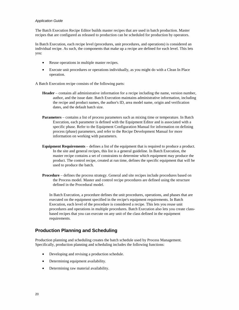
The Batch Execution Recipe Editor builds master recipes that are used in batch production. Master recipes that are configured as released to production can be scheduled for production by operators.
In Batch Execution, each recipe level (procedures, unit procedures, and operations) is considered an individual recipe. As such, the components that make up a recipe are defined for each level. This lets you:
• Reuse operations in multiple master recipes.
• Execute unit procedures or operations individually, as you might do with a Clean In Place operation.
A Batch Execution recipe consists of the following parts:
Header – contains all administrative information for a recipe including the name, version number, author, and the issue date. Batch Execution maintains administrative information, including the recipe and product names, the author's ID, area model name, origin and verification dates, and the default batch size.
Parameters – contains a list of process parameters such as mixing time or temperature. In Batch Execution, each parameter is defined with the Equipment Editor and is associated with a specific phase. Refer to the Equipment Configuration Manual for information on defining process (phase) parameters, and refer to the Recipe Development Manual for more information on working with parameters.
Equipment Requirements – defines a list of the equipment that is required to produce a product. In the site and general recipes, this list is a general guideline. In Batch Execution, the master recipe contains a set of constraints to determine which equipment may produce the product. The control recipe, created at run time, defines the specific equipment that will be used to produce the batch.
Procedure – defines the process strategy. General and site recipes include procedures based on the Process model. Master and control recipe procedures are defined using the structure defined in the Procedural model.
In Batch Execution, a procedure defines the unit procedures, operations, and phases that are executed on the equipment specified in the recipe's equipment requirements. In Batch Execution, each level of the procedure is considered a recipe. This lets you reuse unit procedures and operations in multiple procedures. Batch Execution also lets you create class-based recipes that you can execute on any unit of the class defined in the equipment requirements.
Production Planning and Scheduling
Production planning and scheduling creates the batch schedule used by Process Management. Specifically, production planning and scheduling includes the following functions:
• Developing and revising a production schedule.
• Determining equipment availability.
• Determining raw material availability.

Application Guide
21
Production Schedule
Batch Execution provides production planning at the recipe level, which allows you to schedule batches for production. You have two options for scheduling batches for production:
• Operators or plant supervisors can add batches to the Batch Execution Client's Batch List using the Add Batch command. Additionally, Batch Execution supplies a BatchAdd ActiveX control from which operators can add batches, as well as a BatchList control that provides similar functionality to the Batch Execution Client's Batch List.
• Integrators can create a campaign manager using VBIS. VBIS lets you create a custom application that interfaces with the Batch Execution Server application. Refer to the Mastering Batch Execution section for more information on developing custom applications using VBIS.
Equipment Availability
When using a class-based recipe in automatic mode, Batch Execution automatically allocates resources to batches based on (1) the equipment requirements defined for the recipe, (2) the equipment properties in the area model, and (3) the real-time conditions on the plant-floor.
During batch execution, Batch Execution ensures that the equipment is available and, if it is currently in use, does not allocate the unit to the batch until it is released by the previous batch. To determine the availability of units, you can configure UNIT_READY and UNIT_PRIORITY tags for units in the area model. Prior to allocating a unit to a batch, Batch Execution checks the values of these tags to determine which units are available. For more information on defining these tags, refer to the Equipment Configuration Manual.
Raw Material Availability
There are several approaches that you can take to ensure that the necessary raw materials are available to execute a batch. You can:
• Prompt operators to check ingredient availability prior to executing a batch.
• Before executing a step in a recipe, check the status of an iFIX tag that monitors the amount of ingredient in a tank, for example.
• Build a custom application using VBIS. Refer to the Custom Applications manual for more information on using VBIS.
Process Management
Process management controls batches and resources within a process cell. Process management consists of the following control functions:
• Manage batches by creating a control recipe from the master recipe based on scheduling and equipment information.
• Manage process cell resources by allocating, reserving, and arbitrating conflicts for the equipment required for batches.
• Provide batch and process cell information to Production Information Management.

Application Guide
22
Batch Execution manages the manufacturing process by creating control recipes from the master recipes that are scheduled for production. All the necessary equipment entities are allocated, arbitrated, and controlled using the control recipes and the arbitration information defined for the equipment.
Unit Supervision
Unit supervision ties the recipe to equipment control. The main control functions performed as part of unit supervision include the following:
• Acquire the required units and execute operations.
• Manage unit resources for both the acquired unit and services provided by other units.
• Collect batch and unit information including status changes and derived values, for Process Information Management.
In Batch Execution, the equipment requirements defined in the recipe procedure determine which units a batch can use. For class-based recipes, the equipment requirements also define how to select which unit instance to bind to a unit procedure. During batch execution, Batch Execution allocates the selected units to the batch. The operations, defined in the recipe procedure, are run on the allocated units.
Process Control
Process control provides regulatory and discrete control at the unit, equipment module, and control module levels. Process control provides the following control functions:
• Executes phases by receiving parameters and commands.
• Executes basic control causing changes in equipment and process states.
• Collects data from sensors, derived values, and events that occur during phase execution.
• Sends data to Production Information Management.
The Batch Execution Server performs supervisory control on the equipment modules. Each equipment phase defined in the area model is tied to the equipment module on which the phase executes. Requests and commands defined in the phase control logic cause changes in equipment and process states.
Production Information Management
Production Information Management collects, stores, processes, and reports on production information. This information can then be used in both batch and non-batch related reporting and analysis. The primary focus of this activity, as related to batch processing, is the ability to manage historical data. Managing the historical data includes receiving and storing information, manipulating the data, and producing batch reports.
Batch Execution uses Active Journaling™ to write batch event data, in real-time, to a relational database. You can then access this data using your company's analysis tools. Refer to the Reporting and Analyzing Production Data section for more information on Active Journaling.

Application Guide
23
Process Model The Process model is a result of performing procedural control on the equipment in the process. The Procedural Control model, when mapped to the equipment, provides the processing functions described in the Process model. The relationships between the Procedural Control model and the four lower levels of the Physical model that produce the Process model are shown in the following figure. The process model consists of the following levels:
Process – is the production of a batch using the available equipment. A process consists of a procedure run on a process cell.
Process Stage – is a set of process operations. A process stage results from performing a unit procedure on an equipment unit. A specific set of operation instructions is included in the unit procedure. When a unit is allocated for a particular batch, it executes the instructions using any additional parameters passed to it at execution time.
Process Operation – consists of a set of process actions. A process operation typically transforms material from one state to another. It can be achieved by running an operation on a unit.
Process Action – is a minor processing task. A process action can be achieved by running a phase on either a unit or an equipment module.
Process, Procedural Control, and Physical Models Relationship

Application Guide
24
Linking a Control Recipe to the Equipment
In Batch Execution, a control recipe is linked to the equipment at the phase level. Equipment phases are defined in the area model to represent each phase in the process. A recipe executes the equipment phase, which in turn is tied to the physical equipment on the plant floor and the phase logic in the process controller. The following figure illustrates this relationship.
Linking the Recipe Procedure to the Equipment
Exploring the Sample Application Batch Execution supplies a sample project based on a virtual plant that makes toothpaste. This plant manufactures several flavors of baking soda toothpaste. It does this by creating a baking soda base mixture and an additive mixture that are combined together in a reactor. The toothpaste is then packaged in tubes and pump bottles.
The Batch Execution documentation uses this application to explain Batch Execution concepts and to provide detailed examples. You can use the demo as a reference when developing your own Batch Execution application. Use the demo project to explore Batch Execution from the development to the production stages of a batch manufacturing environment, including:
• A sample area model representing the plant-floor equipment.
• Sample recipes to produce multiple flavors of toothpaste.
You can open the sample project from the Proficy Batch Execution WorkSpace. The project files, by default, are installed into C:\Program Files\Proficy\Proficy Batch Execution\PROJECTS.

Application Guide
25
Designing the Toothpaste Control Strategy Before you can implement any batch application, there are several planning and design tasks to consider. These include:
• Outlining the general procedure required to manufacture the product.
• Identifying the process flow.
• Partitioning the plant equipment.
• Defining the equipment requirements.
The following subsections describe these tasks for the sample toothpaste application. When you have completed the design strategy for implementing Batch Execution, you can begin equipment and recipe development. These tasks are described in the Developing a Batch Execution Project section.
Outlining the General Procedure
The general steps required to make a batch of toothpaste are outlined below.
To make a batch of toothpaste:
1. Add raw material ingredients that comprise the base of the toothpaste into a mixer. The raw material ingredients are baking soda, fluoride, gum, alkaline, and water.
2. Add raw material ingredients that comprise the flavor of the toothpaste into a mixer. The possible flavors are wintergreen, spearmint, peppermint, and bubble gum. All flavors also require a whitening agent.
3. Agitate the base ingredients at a specified speed and duration. While agitating, cool the mixture to a specified temperature.
4. Agitate the flavor ingredients at a certain speed for a specified duration.
5. Test the pH value for the base mixture. If the test results are not within tolerance, add corrective ingredients.
6. When both the base and flavor mixtures are complete, transfer the mixtures into the reactor.
7. Agitate the mixture in the reactor at a specified speed and duration. While agitating, aerate the mixture.
Identifying the Process Flow
Identifying your application's process flow is the first step in automating your plant. A process flow diagram provides a high-level view of your process that groups related process functions.
Partitioning Plant Equipment
In addition to identifying the process flow, you also need to partition your plant equipment. Partitioning your equipment for maximum efficiency is the key to successfully automating your plant. Typically, a Process and Instrumentation Drawing (P&ID) is used to identify and partition the equipment used in a process. The following figure shows the P&ID for the sample toothpaste application.

Application Guide
26
Sample Toothpaste Application P&ID
Equipment Requirements
The production facility contains one process cell consisting of several production lines. Based on the production requirements of the flavored toothpaste process, a line must include:
• Seven tanks to hold raw materials
• Two mixers
• One reactor
• Pipes and valves required to transport solutions
Based on the P&ID in the Sample Toothpaste Application P&ID section, you can divide the process cell into several production lines. Depending on how the recipe is configured, either the operator or Batch Execution can choose the production line based on what mixers are currently available.

Application Guide
27
Other Samples In addition to the Sample Application, Proficy Batch Execution provides other samples for:
• ActiveX Controls – HTML, Visual Basic, and Visual MFC sample projects that you can use to build and test the Proficy Batch Execution ActiveX controls.
• VBIS – Sample applications that demonstrates the VBIS API, a sample campaign manager that uses VBIS, and an EWI Test.
• PLIs – Sample PLI ladder logic for the following programmable controllers:
• The Allen-Bradley ™ PLC5 Series (PLI_REV2_06.RSP). This PLI was written in RSLogix ™ 5.
• The Allen-Bradley ™ SLC/500 (PLI_REV2_06.RSS). This PLI was written in RSLogix 500.
• The Allen-Bradley ™ ControlLogix Processor (PLI_REV4_00.ACD). This PLI was written in RSLogix 5000. This sample uses Data Structures or Direct Addressing. It does not use PLC-5 addressing (recommended), and instead uses RSLinx as an OPC Server providing information directly to Batch Execution.
• The Allen-Bradley ™ ControlLogix ™ Processor (PLI_REV2_06.ACD). This PLI was written in RSLogix 5000. The sample provides a more robust communications method using Allen-Bradley driver and RSLinx ™ through Proficy iFIX as opposed to OPC directly to RSLinx.
• The Siemens S7-300 and S7-400 PLCs (S7_pli_6.zip). This PLI was written with Siemens Step 7 Series software.
• WorkInstruction – Demo project (EWIDemo.wkb) that demonstrates how to use the WorkInstruction feature. It inlcudes two sample EIBs and a Microsoft SourceSafe database that is installed along with the product. Refer to the section WorkInstruction Demo Project section for more details.
You can find the samples of the ActiveX controls, VBIS, and the in the c:\Program Files\Proficy\Proficy Batch Execution\samples folder, if you installed Proficy Batch Execution to the default location. The WorkInstruction demo project, EWIDemo.wkb, is located in the Program Files\Proficy\Proficy Batch Execution\projects folder. The SourceSafe database is located in the Program Files\Proficy\Proficy Batch Execution\projects\EWIDemo\EWISS folder.
Developing a Batch Execution Project The sections that follow discuss the development tasks in Batch Execution and how they are implemented for the sample toothpaste application:
• Development Overview • Developing a Batch Execution Project • Programming the Process Controller • Configuring the Area Model • Developing Recipes

Application Guide
28
• Storing Recipes in the Relational Database • Using the Batch Execution Soft Phase Server • Developing iFIX Pictures
Development Overview As the picture illustrates in the Developing a Batch Execution WorkSpace Project section, developing a Batch Execution application consists of several tasks. Before you can begin any development, you must first have a solid control strategy in place. Refer to the Exploring the Sample Application section for information on designing a control strategy. Once this strategy is in place, you can begin implementing Batch Execution for your application.
The following sections discuss each Batch Execution development task.
Reporting and Analyzing Production Data Accurate and timely reporting capabilities are critical to tracking your facility's production data. This is especially important for food and chemical facilities that need to meet regulatory agency requirements.
You can integrate Batch Execution data with other areas of the manufacturing enterprise. Because the data is stored in a relational database, you can update your enterprise data with Batch Execution data so you always have the latest plant production information available.
The sections that follow discuss the reporting options provided in Batch Execution including:
• Active Journaling
• Archiving process values
• Proficy Plant Applications Batch Analysis Reports
Active Journaling
To satisfy all your reporting requirements, Batch Execution provides Active Journaling. Active Journaling is the process of recording event data in a relational database. The following figure illustrates the Active Journaling architecture.

Application Guide
29
Active Journaling Architecture
Batch Execution lets you configure the types of batch data to archive by providing filtering capabilities. Typically, you will want to configure Batch Execution to archive actual process values. Typical process values include:
• Total amounts produced
• Actual temperature values
• Actual ingredient amounts
Batch Execution does not limit the information you can archive. You can configure your system to report on any value that is important to your process.
For more information on configuring the Batch Archiver, refer to the System Configuration Manual.
Archiving Process Values
To archive process values, you can configure phase reports for each value that you need to archive. Phase reports are parameters that store actual process values or batch values used by the equipment phase. Batch Execution uploads this information from the phase logic in the process controller to the Batch Execution Server after the phase completes. The Batch Execution Archiver can then archive the reports to the relational database.
For example, when a batch of toothpaste completes, you may want to report the actual amount produced.
Application Guide
30
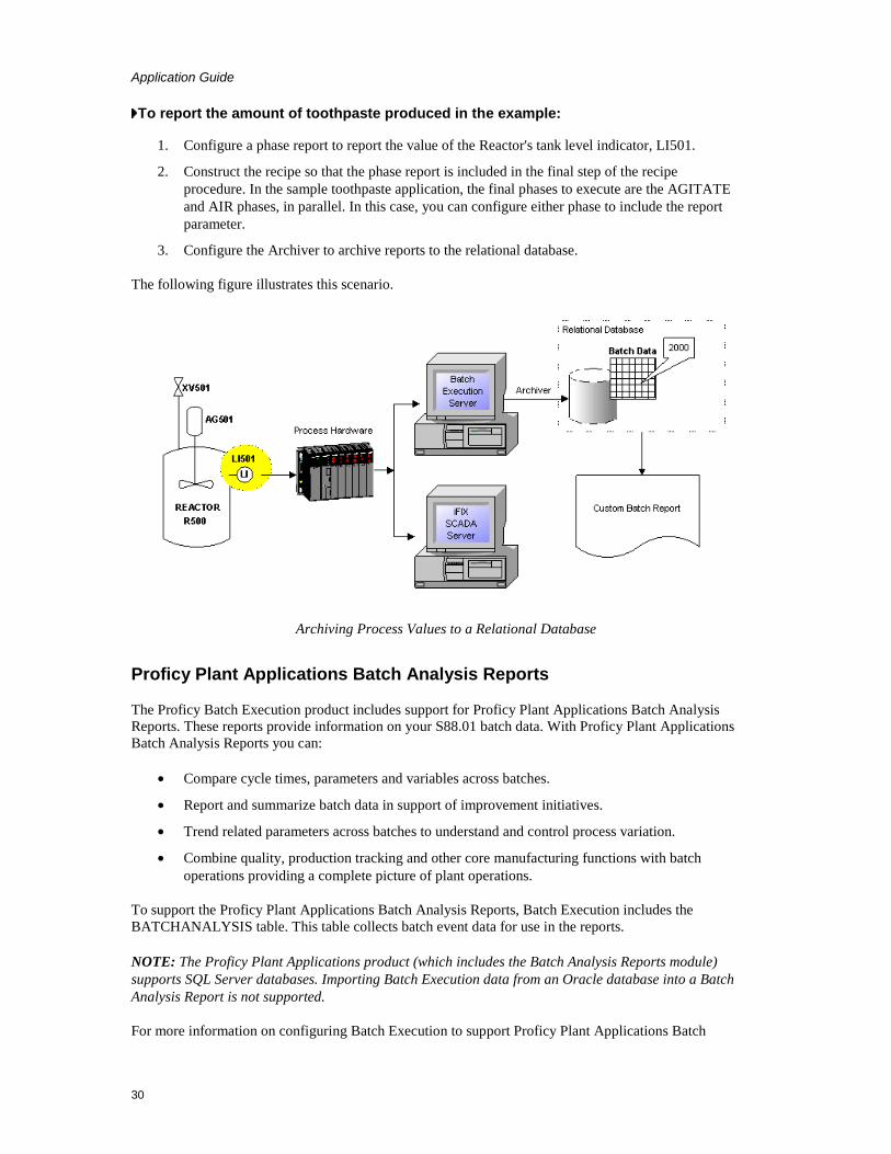
To report the amount of toothpaste produced in the example:
1. Configure a phase report to report the value of the Reactor's tank level indicator, LI501.
2. Construct the recipe so that the phase report is included in the final step of the recipe procedure. In the sample toothpaste application, the final phases to execute are the AGITATE and AIR phases, in parallel. In this case, you can configure either phase to include the report parameter.
3. Configure the Archiver to archive reports to the relational database.
The following figure illustrates this scenario.
Archiving Process Values to a Relational Database
Proficy Plant Applications Batch Analysis Reports
The Proficy Batch Execution product includes support for Proficy Plant Applications Batch Analysis Reports. These reports provide information on your S88.01 batch data. With Proficy Plant Applications Batch Analysis Reports you can:
• Compare cycle times, parameters and variables across batches.
• Report and summarize batch data in support of improvement initiatives.
• Trend related parameters across batches to understand and control process variation.
• Combine quality, production tracking and other core manufacturing functions with batch operations providing a complete picture of plant operations.
To support the Proficy Plant Applications Batch Analysis Reports, Batch Execution includes the BATCHANALYSIS table. This table collects batch event data for use in the reports.
NOTE: The Proficy Plant Applications product (which includes the Batch Analysis Reports module) supports SQL Server databases. Importing Batch Execution data from an Oracle database into a Batch Analysis Report is not supported.
For more information on configuring Batch Execution to support Proficy Plant Applications Batch

Application Guide
31
Analysis, refer to the System Configuration manual. For information on configuring Proficy Plant Applications Batch Analysis, refer to the Plant Applications Batch Analysis documentation.
Developing a Batch Execution WorkSpace Project The Proficy Batch Execution WorkSpace is the starting point for using Batch Execution and is where the majority of the developers' time is spent. The Proficy Batch Execution WorkSpace provides an integrated and flexible environment to develop and configure projects. A project is the entire set of items needed to deliver a batch solution.
The sample toothpaste application contains the following GE Batch Execution project items:
• Configuration files
• Area model
• Recipes
• Embedded OLE-compliant documents
Similar to the Microsoft Explorer, the Proficy Batch Execution WorkSpace organizes a project into folders. Each folder stores the common types of items in a project, such as pictures, configuration files, and recipes. Each item is associated with a folder. This makes locating an item as simple as opening the associated folder.
The following figure illustrates each Batch Execution development task. Notice that you can perform most development tasks in parallel. However, it is important that all members of your development team have a clear understanding of the design specifications for your system.

Application Guide
32
Batch Execution Development Task Overview
Embedding OLE Documents
The Proficy Batch Execution WorkSpace is object linking and embedding (OLE) compliant. This means that you can integrate documents from other OLE-compliant programs, such as Word and Excel, in one easy step. This feature allows you to work on a Word document or an Excel workbook directly from the Proficy Batch Execution WorkSpace. For example, you may want to link your design specifications or schedules to a project. This way, they are readily available for you to reference at any time.
Like Batch Execution project items, the documents from OLE-compliant programs appear in the work area that the Proficy Batch Execution WorkSpace supplies when you create or edit them.
Using the Proficy iFIX WorkSpace
As an alternative to developing a project in the Batch Execution WorkSpace, the entire Batch Execution project can be developed and maintained through the Proficy iFIX WorkSpace. The Proficy iFIX WorkSpace serves as a single development environment for both iFIX and Batch Execution. You can access the Batch Execution books, Batch Execution Configuration dialog box, Batch Execution equipment, and recipes from the iFIX WorkSpace tree, as shown in the following figure.

Application Guide
33
Batch Execution Entries in the Proficy iFIX WorkSpace Tree
Programming the Process Controller There are two areas of development when programming your process controller:
• Programming the Phase Logic Interface (PLI).
• Programming the phase logic.
The figure in the Understanding the PLI section illustrates the relationship between these two areas.
Note that the sample application is not tied to real I/O. Instead, it uses the Soft Phase Server OPC Simulator.
Understanding the PLI
The PLI is the standard interface between the Batch Execution Server and the phase logic. The PLI is the Batch Execution-specific portion of the phase and controls the state transitions for phases. Phases in Batch Execution must follow a specific state transition path. This path is based on the state transitions outlined in the ISA S88.01 Batch Control Standard.
For more information on programming the PLI, refer to the PLI Development Manual.

Application Guide
34
Programming the Process Controller
Understanding the Phase Logic
The phase logic contains the instructions to sequence the individual pieces of equipment connected to the physical devices. It is the code that contains the control steps, such as opening a valve, starting a pump, or stopping a totalizer. How you program your phases depends entirely on your process. However, you can implement design techniques to make your phase logic modular, generic, and maintainable.
For more information on programming and designing phase logic, refer to the Phase Programming Manual.
Programming Requests
Batch Execution provides a series of request functions that enable the phase logic to request the Batch Execution Server to perform specific actions, such as downloading phase parameters and uploading phase report values.
For example, you may have an Agitate phase that requires a value to set the mixer speed. In this case, you can program a Download Parameter Request in the Agitate phase logic to download the mixer speed parameter value.
For more information on programming requests into your phase logic, refer to the Phase Programming Manual.
Configuring the Area Model The area model provides a graphical, hierarchical representation of the process equipment in your plant. This database is then used by other areas of Batch Execution to build recipes and execute

Application Guide
35
batches. Once the area model is configured, it is unlikely that it will require major changes. It may require some maintenance from time-to-time, if you modify the process equipment on the plant floor.
Based on the equipment requirements outlined in the Exploring the Sample Application section, the following equipment is defined for the sample application. The figure that follows illustrates a sample equipment configuration.
Area
The sample application's equipment is contained in an area called Area1. This is the default area name provided by Batch Execution.
Process Cell
Within Area1 is one process cell called Toothpaste. This process cell contains all the equipment required to produce a batch of toothpaste.
Sample Application Equipment Configuration

Application Guide
36
Unit Classes
The toothpaste process cell in the sample application contains three unit classes:
• A Raw unit class is defined for seven similar storage tanks.
• A Mixer unit class is defined for three similar mixers.
• A Reactor unit class is defined for two similar reactors.
Unit Instances
Instances of each unit class are created to represent each physical unit in the process cell. Each unit instance inherits its unit class properties, including any unit tag classes defined for the unit class. At the instance level, properties such as the equipment ID and unit tags are defined based on the unit's physical properties. The previous figure with the sample equipment configuration illustrates each unit instance defined for the sample application and their associated unit classes.
Standard Equipment Phases
Standard equipment phases configured in the Equipment Editor are equipment-centric, meaning that you are not defining the control logic for the phase, you are configuring the equipment module on which the phase executes. The actual control logic for the phase resides in the process controller, not in the Equipment Editor. This type of phase is called a standard equipment phase.
Your task in the Equipment Editor is to create a representation of each equipment phase in the process controller and tie it to the equipment on which the equipment phase executes. In order to do this, you must have a complete understanding of how the equipment phases are programmed in the process controller. The previous figure with the sample equipment configuration illustrates each unit instance defined for the sample application and their associated unit classes and equipment phases. There are no Batch Direct phases in the sample application.
Batch Direct Equipment Phases
With Batch Direct phases, the PLI logic is built directly into the phase. This PLI logic provides a standard interface between the Batch Execution Server and the equipment phase. What that means, is that you can use batch direct phases to directly communicate with existing PLC programs located on your process controllers, without having to rewrite any additional PLI logic. With Batch Direct phases, you have a simpler interface to the process controller.
Your task in the Equipment Editor is to create a representation of all equipment phases (standard and Batch Direct) and tie it each phase to the equipment on which it executes. In order to do this for Batch Direct phases, you must have a complete understanding of how the phase logic is used on the process controller.
Developing Recipes The general procedure (outlined in the Exploring the Sample Application section) is translated into a master recipe procedure called Make_Toothpaste. This procedure is illustrated in the Using Class-Based Recipes section.
Recipe development is generally an ongoing process. As you enhance your products, you need to modify recipes to incorporate new production requirements. The sample toothpaste recipes are

Application Guide
37
designed with this requirement in mind. It does this by incorporating the following Batch Execution features:
• Active Binding™
• Recipe parameters
• Class-based recipes
• Parallel Processing
The following sections describe each feature and how it is used to meet the requirements of the sample toothpaste application. For additional information on any of these features, refer to the Recipe Development Manual.
Using Active Binding
Requirement:
Maximize the plant's equipment usage.
Solution:
Batch Execution provides Active Binding. Active Binding allows you to bind and re-bind unit procedures to units at multiple stages in a batch's life cycle, including when a batch is created or in production. Recipe authors can configure recipes to automatically allocate equipment to batches based on (1) the properties of the equipment model, and (2) the real-time conditions on the plant floor. Refer to the Mastering Batch Execution section for more information.
Using Recipe Parameters
Requirement:
The general procedure requirement for the toothpaste application is to manufacture several flavors of toothpaste.
Solution:
Batch Execution lets you create recipe parameters to define the amount of each ingredient required for the types of toothpaste in production. By varying the amount of each ingredient, different types of toothpaste are made with the same master recipe. For example, to make mint-flavored toothpaste, the parameter MINT is set to 60. To make regular-flavored toothpaste, MINT is set to 0.
Using Class-Based Recipes
Requirement:
The toothpaste application must be able to select the equipment on which the recipe executes based on which units are available when the batch is scheduled for production.

Application Guide
38
Solution:
Batch Execution lets you build class-based recipes that allow the BASE and ADDITIVE unit procedures to use any mixer defined in the process cell. This feature lets you create recipes that are not tied to a specific piece of equipment. You can alo configure the equipment requirements for the BASE and ADDITIVE unit procedures to automatically bind units to these procedures during batch execution.
Make_Toothpaste Procedure
Parallel Processing
Requirement:
The requirements of the general procedure state that the base mixture must be agitated and cooled simultaneously.

Application Guide
39
Solution:
Batch Execution lets you perform parallel processing simply by constructing the recipe's sequential function chart to do so. In the MAKE_BASE operation, the AGITATE and COOL phases run in parallel. When both phases are complete, control moves to the QA_TEST phase for testing.
Storing Recipes in the Relational Database Batch Execution can store recipes in both file-based and SQL-based formats. The storage type is set at the project level, meaning that all recipes within a project must be stored in either SQL or file format. It is transparent to the recipe parameter or whether the recipe is file-based or SQL-based; the recipes are built in the same manner. Batch Execution handles the storage type internally.
Batch Execution stores and retrieves recipe data based on the Batch Execution Logical Data model. The Logical Data model is the table structures and rules that represent the storage of Batch Execution recipes in a relational database.
If you plan to store recipes in the relational database, developers need to consider the following:
• Recipe storage types are set at the project level, meaning that all recipes within a single project must be either SQL-based or file-based.
• Configure the recipe tables in your relational database. Batch Execution provides scripts that build these tables for you.
• Configure a data source so that Batch Execution knows where to store and retrieve the recipe data.
For more information on storing recipes in a relational database, refer to the Recipe Development Manual. For more information on configuring the Logical Data model in your relational database, refer to the System Configuration Manual.
Using the Batch Execution Soft Phase Server The Soft Phase Server is an OPC Server that acts as a PC-based controller between the Batch Execution Server and soft phases. Soft phases are Batch Execution phases whose phase logic is provided by scripting or programming outside of a hardware controller (PLC or DCS) environment. You can implement soft phases either within iFIX or with any development systems that supports OLE Automation servers and OLE for Process Control (OPC), including Visual Basic, C++, or Java. In every case, communication between the Soft Phase Server, the Batch Execution Server, and the phase logic is accomplished using OPC.
Soft phases use the phase logic as described in the Phase Programming Manual. Implementation of the PLI, that is normally part of the hardware controller, is part of the Soft Phase Server. Refer to the PLI Development Manual for detailed information on PLI.
During the development stage, you can model and test your equipment configuration and recipes using the Soft Phase Server in Simulation Mode. With the Batch Execution Soft Phase Server, you can build an area model and tie the equipment entities to the Batch Execution Soft Phase Server simulated points, rather than actual I/O points. After you build the recipes and area model, you can then simulate production by executing batches. Only 50 parameters, 50 reports, and 50 request qualifiers per phase are supported.

Application Guide
40
NOTE: You must configure each phase in the Soft Phase Server to run in Simulation Mode if you want to use the Soft Phase Server as a simulator.
The Batch Execution Soft Phase Server uses your equipment phases and related parameters to simulate your batch operation. Specifically, you can use the Batch Execution Soft Phase Server to:
• Test phase configuration and synchronization.
• Test new recipes.
• Determine how long batches will run.
For more information on using the Batch Execution Soft Phase Server refer to the Batch Execution Soft Phase Server online help or Configuring the Soft Phase Server in the System Configuration Manual.
Developing iFIX Pictures Incorporating iFIX pictures into your system requires an initial investment in time to design and create each required picture. However, the results of those efforts are pictures that can provide a range of views into the batch processing environment, from an overview of a plant's operations to a detailed representation of a specific piece of equipment.
For example, in the sample toothpaste application, you might want to use iFIX pictures for the following:
• A plant overview picture.
• A line control picture.
• Unit control pictures for both the mixer and the reactor unit classes.
• Batch status picture that lets operators monitor batches from outside the Batch Execution Client.
Refer to the Creating Pictures manual for more information on iFIX pictures.
Batch Execution Operations The sections that follow discuss the operations tasks in Batch Execution. You can explore these tasks using the sample recipe procedure, Make_Toothpaste, provided in the Proficy Batch Execution WorkSpace demo project. For additional information on Batch Execution operations, refer to the Operations Manual.
Operations Overview Batch Execution provides operators with the following environments for controlling batches:
• Nine graphical screens in the Batch Execution Client application.
• The ability to incorporate iFIX pictures into your operations environment.

Application Guide
41
• A set of ActiveX controls that you can:
• Embed directly into iFIX pictures, web browsers, or any OLE compliant container.
• Incorporate into iFIX pictures (using the Runtask command).
The following figure illustrates the operations tasks and the order in which they are performed.
Operations Task Overview
Understanding Batch Execution The Batch Execution Server controls the execution of a batch based on the phase state transition logic in the Phase Logic Interface (PLI). The purpose of the PLI is to control the transitions between the phase states.

Application Guide
42
The PLI is the standard interface to the project-specific phase logic. The PLI receives commands from the Batch Execution Server or the operator and then initiates the different components of the phase-specific control logic. This communication flow, shown in the following figure, ultimately controls the execution of a batch.
Batch Execution Communication Flow
Understanding States
Batch execution follows a series of state transitions. These transitions are based on the procedural states defined in the ISA S88.01 Batch Control Standard.
The batch state and the states of phases running within a batch are updated as a batch progresses. These states are displayed in several locations in the Client; every screen has either a field or a column where the state information is visible.
An operator can only issue commands that are valid for the current state. For example, if a batch is in the Running state, the operator can issue several commands including Stop, Abort, and Hold.
The following figure illustrates the valid state transitions paths.

Application Guide
43
Valid State Transition Paths
Controlling and Monitoring Batches Batch Execution provides several options for controlling and monitoring batches. The Batch Execution Client provides nine graphical screens that operators can use to perform the following tasks during batch production:
• Create and start batches.
• Bind and rebind equipment to batches. Depending on how the recipe was configured, Batch Execution can (1) prompt the operator to select a unit to allocate to a unit procedure, or (2) automatically bind unit procedures to units. Given the appropriate rights, operators can rebind unit procedures to units during batch production.
• Monitor a batch as it executes from a variety of viewpoints. The most popular is the SFC View screen, which graphically displays a batch as it executes each step.
• Issue commands such as Stopping, Holding, Aborting, and Restarting batches.
• View batch journal data for the current batch and for previous batches.
• Acknowledge operator prompts, binding prompts and transition breakpoint prompts.
• Control individual phases.
• Arbitrate resources.
• View alarms.

Application Guide
44
Using the ActiveX Controls
As an alternative to using the Batch Execution Client, Batch Execution supplies a set of ActiveX controls that you can use to control and monitor batches. The ActiveX controls included with Batch Execution are as follows:
• BatchList
• BatchAdd
• BatchRecipeList
• BatchOperatorPromptsList
• BatchBindingPromptsList
• BatchAlarmList
• BatchManualPhase
• BatchSFC
• BatchActivePhaseList
• BatchCampaignManager
WorkInstruction includes the following control:
• EWI ActiveX control
These controls can be run from the following containers:
• iFIX Run-time environment
• Any ActiveX or OLE container, such as web browsers or Visual Basic
Additionally, you can incorporate the ActiveX controls into an iFIX picture using the Runtask command. To do this, first place the control into a container application, such as a Visual Basic form, and save it as an executable (EXE). Then, use the Runtask command in iFIX to run the executable.
The controls contain most of the same functionality provided in the corresponding view in the Batch Execution Client. The following figure shows an example of the BatchList Control supplied with Batch Execution.
BatchList ActiveX Control

Application Guide
45
Developing VBIS Applications
In addition to the Batch Execution Client and the ActiveX controls, you can use VBIS to develop custom applications. For example, you can develop VBIS applications to:
• Create a campaign manager. VBIS provides a scheduling function that lets you automate the process of adding batches to the Batch List in the Batch Execution Client. In this way, you can integrate your corporate scheduling system into Batch Execution so that your production schedules are always up-to-date.
• Automate the process of starting batches. VBIS provides a function containing all the necessary parameters for binding equipment and specifying parameter values. This is the mechanism that external programs can use to control batch execution.
• Develop a custom VBIS application that monitors the state of batches. By polling the Batch Execution Server for the current batch state, your custom application can determine when a batch completes. This technique is useful in many types of applications, such as a campaign manager.
These are just a few examples of VBIS applications. You can develop numerous VBIS applications to suit your particular needs.
Refer to the Custom Applications manual for more information on VBIS.
Using the Campaign Manager
The Campaign Manager provides a simple way for you to manage batches associated with a campaign. A campaign is the execution of multiple, similar batches, which are typically required to fill a process order; process orders are orders where one or more customer orders are grouped together by product and assigned to specific production equipment. The Campaign Manager creates a campaign with parameters you provide. It determines the number of batches required to satisfy an order, and creates and schedules the batches necessary to satisfy campaign order requirements. After creating campaigns, you can use the Campaign Manager to monitor campaigns and their individual batches.
The Campaign Manager offers electronic signature capability, allowing you to provide user authentication prior to execution of a command. It also allows you to restrict access to features by user, such as the ability to create or remove campaigns.
The Campaign Manager has three components – the Campaign Client, the Campaign Server, and the Campaign Database. The Campaign Client is an ActiveX control that, when hosted in an ActiveX container, provides you with an interface to create and manage campaigns. The Campaign Server is a service that runs in parallel with the Batch Server and controls the triggering and execution of campaigns. The Campaign Database provides storage for the campaign data.
For more information on Campaign Manager, refer to the Campaign Manager guide and the Custom Applications manual.
Using Proficy Workflow to Manage Campaigns
You can easily integrate Batch Campaign Management into your manufacturing process using Proficy Workflow. Doing so allows you to easily monitor and modify your process based on real time needs, while managing all of it, including campaigns and batch production, from a single location.
Using the Batch service provider with Proficy Workflow allows you to avoid the errors that are inherent in
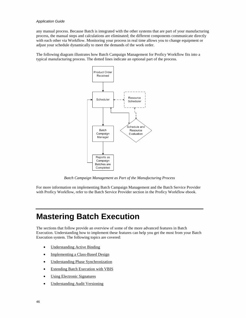
Application Guide
46
any manual process. Because Batch is integrated with the other systems that are part of your manufacturing process, the manual steps and calculations are eliminated; the different components communicate directly with each other via Workflow. Monitoring your process in real time allows you to change equipment or adjust your schedule dynamically to meet the demands of the work order.
The following diagram illustrates how Batch Campaign Management for Proficy Workflow fits into a typical manufacturing process. The dotted lines indicate an optional part of the process.
Batch Campaign Management as Part of the Manufacturing Process
For more information on implementing Batch Campaign Management and the Batch Service Provider with Proficy Workflow, refer to the Batch Service Provider section in the Proficy Workflow ebook.
Mastering Batch Execution The sections that follow provide an overview of some of the more advanced features in Batch Execution. Understanding how to implement these features can help you get the most from your Batch Execution system. The following topics are covered:
• Understanding Active Binding
• Implementing a Class-Based Design
• Understanding Phase Synchronization
• Extending Batch Execution with VBIS
• Using Electronic Signatures
• Understanding Audit Versioning

Application Guide
47
Using Proficy Plant Applications Batch Analysis Reports You can import your Batch Execution event data into Proficy Plant Applications Batch Analysis Reports. If you use the Proficy Plant Applications Batch Analysis product with Batch Execution, the following events would be part of a Batch Analysis report:
• Active Binding • Param Download Verify • Prompt • Recipe Header • Recipe Value • Recipe Value Change • Report • State Change • State Command • Step Activity
These events are listed in the Batch Execution Configuration dialog box, in the Archiver tab, under Event Filters. You can access the Batch Execution Configuration dialog box from the Batch Execution Workspace by double-clicking the Batch Execution Configuration in the WorkSpace tree. You can also double-click the Batch Execution Configuration in the Proficy iFIX WorkSpace tree to view this dialog box.
For information on how to configure Batch Execution to use Proficy Plant Applications Batch Analysis Reports, refer to the Plant Applications Batch Analysis Reports Configuration section in the System Configuration manual.
For steps on how to configure the Proficy Plant Applications Batch Analysis product, refer to the Plant Applications Batch Analysis documentation.
Understanding Active Binding To get maximum productivity from your equipment, Batch Execution supports Active Binding. Active Binding allows you to automatically bind a unit procedure to a physical unit. Batch Execution can bind units at batch creation and re-bind units during batch production.
Implementing Active Binding spans several areas of Batch Execution, including:
• Configuring the area model for Active Binding.
• Configuring recipes for Active Binding.

Application Guide
48
Configuring Active Binding in the Area Model
To provide Batch Execution with sufficient information to intelligently select an appropriate unit, you can configure the following in your area model:
Equipment pathing – Within a process cell, you can specify the physical connections between units. These connections are graphically represented with connection lines. When the batch procedure executes, each selected unit must be within a valid equipment path.
Equipment capacity – For each unit, you can specify the unit's maximum capacity. When the recipe executes, the selected unit must meet the capacity requirement defined for the unit procedure.
Equipment status tags – For each unit, you can specify a Unit Ready status and a Unit Priority status, to indicate the unit's current availability and priority rating. When the recipe executes, the unit selected by the Batch Execution Server must be available, as defined by its Unit Ready tag. If more than one unit is ready and available, the Batch Execution Server selects the unit with the highest priority, as defined be the unit's Unit Priority tag.
These dependencies are optional, meaning that Batch Execution can automatically allocate units if none of these dependencies are configured. However, to take full advantage of Active Binding, you most likely will want to provide Batch Execution with as much information as possible to make the most intelligent selection when the recipe executes. For example, if unit capacity is important to your process, you should configure equipment capacity to ensure that appropriate units are allocated to batches.
Active Binding Configuration Based on Priority or Availability
You can allocate the units based on availability, the default setting for Active Binding. Or, you can allocate the units based on the unit priority tags (in the PLC, Soft Phase Server, PDB, and so on). You configure this information from the WorkSpace in the Batch Execution Configuration dialog box, under the Server tab.
Configuring Active Binding in Recipes
In the equipment requirements for your recipes, you can specify how you want Batch Execution to bind batches to equipment (units). This includes the ability to automatically bind batches to units.
Batch Execution provides three choices for binding equipment to recipes:
Automatic binding – this method allows the Batch Execution Server to select the unit to bind to the unit procedure at run time based on criteria defined in both the unit procedure and in the area model.
Operator prompt – this method prompts the operator to select a unit or to specify an automatic selection just before the unit procedure runs.
Specify at Batch Creation – this method requires the operator to select a unit to bind to the unit procedure when the batch is added to the batch list.
Additionally, you can assign operators rights to modify the binding at batch creation, during batch execution, or both.

Application Guide
49
You can incorporate the following features into your recipes to provide the Batch Execution Server with additional information to select units:
Jacobson Links – indicate whether the units used for two unit procedures must be physically connected. Jacobson Links are connections that are drawn within a recipe's sequential function chart (SFC) that represent a necessary physical connection between unit procedures.
Forced Binding – indicates whether two unit procedures must run on the same unit or must run on different units.
Unit Procedure Capacity – indicates the amount of material the selected unit must be able to transfer, process, or contain to run the unit procedure. This value can be scaled with the batch scale.
Example: Active Binding Area Model Configuration
The equipment configuration for the sample toothpaste application takes advantage of equipment pathing, equipment capacity, and equipment status to provide Batch Execution with data to ensure that suitable units are allocated to batches.
Equipment Pathing
Configuring equipment paths ensures that the units selected for a batch are within a valid execution path. The equipment pathing is based on the physical connections that exist between units on the plant floor. In the sample application, the following physical connections are configured:
1. The base ingredients (water, baking soda, gum, fluoride, and Ph_additive) are on one header feeding MIX1, MIX2 and MIX3.
2. The additive ingredients (flavoring and whitener) are on a second header that feeds into MIX2 and MIX3.
3. All three mixers feed into the REACTFLAVOR unit, while the REACTPLAIN unit is fed only by MIX1.

Application Guide
50
The following figure illustrates the equipment pathing configured for the sample toothpaste application.
Sample Execution Path
Unit Capacities and Statuses
The following table lists the equipment capacity settings and the current equipment status for each unit instance in the MIXER class.
Sample Capacities and Status for the MIXER Unit Class
Unit Instance Capacity Amount Current Equipment Status
MIX1 1000 Liters MIX1_READY=0
MIX1_PRIORITY=0
MIX2 2000 Liters MIX2_READY=0
MIX2_PRIORITY=0

Application Guide
51
Sample Capacities and Status for the MIXER Unit Class
Unit Instance Capacity Amount Current Equipment Status
MIX3 500 Liters MIX3_READY=0
MIX3_PRIORITY=0
REACTPLAIN 1000 Liters REACTPLAIN_READY=0
REACTPLAIN_PRIORITY=1
REACTFLAVOR 2000 Liters REACTFLAVOR_READY=0
REACTFLAVOR_PRIORITY=2
Example: Active Binding Recipe Configuration
Coupled with the area model configuration, the Make_Toothpaste recipe procedure shown in the following figure uses Jacobson Links ™ , forced bindings, and unit procedure capacity requirements to ensure that suitable units are allocated to batches.
Make_Toothpaste Recipe Procedure
Jacobson Links
The Jacobson Links, illustrated in the above figure, require that the units used by the ADDITIVE and BASE unit procedures are physically connected to the unit that is bound to the FINAL unit procedure.

Application Guide
52
Forced Bindings
The following table shows the unit procedure bindings that are configured for the Make_Toothpaste procedure. In this case, the BASE and ADDITIVE units are forced to run on different units.
Sample Unit Procedure Bindings
Unit Procedure Unit Procedure Same Units? Different Units?
BASE ADDITIVE No Yes
Equipment Requirements
Assume that the equipment requirements listed in the following table exist for the BASE and ADDITIVE unit procedures in the sample application.
Sample Recipe Equipment Requirements
Unit Procedure
Unit Class
Capacity Requirement
Bind Type Operator Rights
BASE MIXER 1000 Liters Specify at Batch Creation
Operator can modify binding during batch execution.
ADDITIVE MIXER 200 Liters Specify at Batch Creation
Operator can modify binding during batch execution.
FINAL REACTOR 1000 Liters Specify at Batch Creation
Operator can modify binding during batch execution.
Example: Active Binding at Run Time
Assume that a batch is added to the Batch List in the Batch Execution Client for the Make_Toothpaste recipe procedure. Based on the configurations and requirements outlined above, the following sequence of events occurs:
1. Batch Execution selects the default unit for the FINAL unit procedure. For this example, let's assume Batch Execution binds the REACTFLAVOR unit to the FINAL unit procedure.
NOTE: You can modify the default unit at batch creation.
2. The operator starts the batch.
3. When both the BASE and ADDITIVE unit procedures are complete, the FINAL unit procedure begins executing on the REACTFLAVOR unit.

Application Guide
53
Implementing a Class-Based Design Your main design goal when developing recipes is to create small, flexible operations that can be reused and recombined in different ways. This approach minimizes the number of operations you need to create and maintain while providing you with the flexibility and power available in Batch Execution. For example, instead of creating five custom operations for five different mixers, consider designing one generic operation that can be used by the five mixers.
A class-based design lets you to develop recipes that can run on a class of units, rather than a specific unit. Furthermore, you can configure these recipes for Active Binding to maximize the use of your plant's equipment. Class-based recipes let you develop flexible operations that you can reuse and recombine in different ways. Implementing a class-based design requires that you configure the following:
• In the area model, configure unit classes, and then define each unit instance with the class.
• When defining the equipment requirements for a recipe, specify that the recipe is class-based. This indicates that the recipe can execute on any one of the units within the specified unit class. You need to specify the default unit as well.
• Use recipe parameters as placeholders for specific process values. A recipe parameter is a variable that represents a process value. By including a recipe parameter in an operation, you make it generic and reusable because the recipe parameter acts as a placeholder for specific values. Recipe parameters also override the hard-coded value in a phase and let you specify any value you need depending on the batch in production. Once a value is specified, the value is passed to a phase in the area model.
Refer to the Recipe Development Manual for more information on creating class-based recipes and using recipe parameters.
Example: Class-Based Design
The sample toothpaste application uses a class-based design. Each recipe level has a default unit, but it can run other units since it is class-based. The area model contains three unit classes: RAW, MIXER, and REACTOR. The unit procedures in the Make_Toothpaste recipe procedure are configured as class-based recipes as follows:
• The BASE and ADDITIVE unit procedures can run on any unit in the MIXER class. The MIXER class contains the MIX1, MIX2, and MIX3 unit instances. The default unit for BASE is MIX1. The default unit for ADDITIVE is MIX2.
• The FINAL unit procedure can run any unit in the REACTOR class. The REACTOR class contains the REACTPLAIN and REACTFLAVOR units. The default unit for FINAL is REACTFLAVOR.
During Active Binding, the Batch Execution Server selects the default unit or the operator selects the unit based on the equipment requirements defined in the recipe coupled with the equipment configuration defined in the area model. Refer to the Understanding Active Binding section for more information on configuring recipes and the area model for Active Binding.

Application Guide
54
Understanding Phase Synchronization Depending on your needs, you may want one phase to communicate with another phase. Typically, this happens when you need to synchronize the actions of both phases.
In order for synchronized phases to run, all phases must be active simultaneously. The first phase in the group sends a request to the Batch Execution Server. The Batch Execution Server does not clear this request until the other phases in the phase link group send requests to the Batch Execution Server, too. The Batch Execution Server then clears all requests simultaneously.
Typically, you synchronize phases when transferring materials from one unit to another. Configuring phase synchronization spans several areas of Batch Execution development. Each task is described below:
• In the phase logic, program each phase in the synchronization group to:
• Send a message to each phase in the synchronization group.
• Wait for messages from each phase in the synchronization group.
When all phases have sent and received messages from all other phases in the synchronization group, the phases are synchronized.
• During equipment configuration, for each phase in the synchronization group:
• Specify the number of phase partners. Phase partners identify the number of phases with which the phase can communicate simultaneously.
• Depending on the type of request, you may need to increment the number of phase requests to account for the Send Message and Wait or the Receive Message request that is programmed in the phase logic. For example, entering 1 as the number of requests creates a phase tag called PHASE_Q01, entering 2 creates two phase tags, PHASE_Q01 and PHASE_Q02, and so on.
Refer to the Equipment Configuration Manual for more information on configuring phases.
• During recipe development, create phase link groups to synchronize a group of phases. A phase link group is a list of phases that communicate with each other. Each phase can belong to different operations but they must reside in the same procedure. Each phase in the link group must have the same number of message partners.
Refer to the Recipe Development Manual for more information on phase link groups.
Example: Phase Synchronization
The figure that follows illustrates an example of phase synchronization. In this example, the material from the BASE and ADDITIVE unit procedures need to be simultaneously transferred into the reactor before the FINAL unit procedure can begin.
The unit procedures XFR_BASE and XFR_ADD each have phases called XFR_OUT_LINK. These phases transfer material to the unit procedure XFR_FINAL, which has a phase called XFR_IN_LINK. In order for the transfer to be successful, these three phases must be synchronized with each other. The valves in the two XFR_OUT_LINK phases must be opened to transfer the material, and the valve in the XFR_IN_LINK must be opened to accept the material.

Application Guide
55
For information on programming phases to perform phases for synchronization, refer to the Phase Programming Manual.
Example of a Recipe that Synchronizes Phases
Area Model Configuration
In the area model for the example, each phase in the synchronization group is configured as follows:
Phase Class Number of Message Partners Number of Request Tags
XFER_OUT_LINK 2 1
XFER_IN_LINK 2 1
The number of message partners is set to two because each phase must communicate with two other phase instances. The number of request tags is set to one to account for the Send Message request that needs to be programmed into the phase logic.

Application Guide
56
Recipe Configuration
To configure the phase synchronization for the recipe, do the following:
• Create the SFC for the Make_Toothpaste procedure that uses AND structures for the XFER_BASE, XFER_FINAL, and XFER_ADD unit procedures, which configures them to run in parallel.
• Configure forced bindings as follows:
• The BASE and XFER_BASE unit procedures must run on the same unit.
• The ADDITIVE and XFER_ADD unit procedures must run on the same unit.
• The FINAL and XFER_FINAL unit procedures must run on the same unit.
• Create Jacobson Links to specify that the units allocated to the XFER_ADD and XFER_BASE unit procedures must be physically connected to the unit allocated to the XFER_FINAL unit procedure.
• Create a phase link group that contains:
• The XFER_OUT_LNK phases for both the XFER_BASE and XFER_ADD unit procedures.
• The XFER_IN_LNK phase for the XFER_FINAL unit procedure.
Phase Logic Configuration
To ensure that the XFER_OUT_LNK and the XFER_IN_LNK phases are in exactly the proper state before they proceed, program the phases in your example to use the Send Message and Wait request and the Receive Message request to synchronize the three phases. This is illustrated in the following figure. The Send Message request functions as the Master and the Receive Message request functions as the Slave during phase synchronization.
Configuring the Phase Logic for Synchronization

Application Guide
57
As illustrated in previous figure, the XFER_IN_LNK phases and the XFER_OUT_LNK phase synchronize the transfer of materials from one unit to another in the example. Before the material is transferred:
1. When the XFER_BASE unit procedure starts executing, the logic in the XFER_OUT_LINK phase issues a Receive Message request to the Batch Execution Server. The Batch Execution Server stores this in its message queue.
2. When the XFER_ADD unit procedure starts executing, the logic in the XFER_OUT_LINK phase issues a Receive Message request to the Batch Execution Server. The Batch Execution Server stores this in its message queue.
3. When the XFER_FINAL unit procedure starts executing, the logic in the XFER_IN_LNK phase issues a Send Message and Wait request to the Batch Execution Server.
4. The Batch Execution Server looks for the matching message ID in the message queue.
5. The Batch Execution Server transfers the message values (if any).
6. The XFER_IN_LNK and both the XFER_OUT_LNK phases continue executing and the material is transferred.
The following table lists the requests that are used to accomplish this synchronization. Upon receiving the Receive Message request from the XFER_OUT_LNK phase, the Batch Execution Server stores message ID 80 in the message queue. Upon receiving the Send Message and Wait request from the XFER_IN_LNK phase, the Batch Execution Server searches within the phase link group for a match to message ID 80 in the message queue. When the message ID is located, the Request register is cleared, and the phases are allowed to continue executing.
Phase Synchronization Requests
Phase Type of Request
Request Syntax
Description
XFER_IN_LNK Send Message and Wait
PHASE_RQ = 5180
PHASE_Q01 = 2
The XFER_OUT_LNK phase sends a message ID of 80 to the Batch Execution Server.
The phase waits for a response from 2 phase before continuing.
XFER_OUT_LNK Receive Message
PHASE_RQ = 5580
The XFER_IN_LNK phase waits to receive a message ID of 80.
Extending Batch Execution with VBIS Batch Execution is an open system that lets you integrate Batch Execution data with multiple systems. VBIS provides a set of functions that allow third-party applications to exchange information with and control Batch Execution without the use of the Batch Execution Client. In addition, Batch Execution supplies a set of ActiveX controls that you can incorporate into your custom applications.

Application Guide
58
For instance, using VBIS you can develop custom applications that can:
• Act as a campaign manager.
• Manipulate SQL-based recipes.
Example
You might create a campaign manager by making VBIS interface calls that do the following:
1. Schedule a batch.
2. Bind the units required by the batch.
3. Run a batch.
4. Enter a loop to request the current batch state.
5. When the state becomes complete, exit the loop and remove the batch from the batch list.
For information on VBIS, refer to the Custom Applications manual.
Integrating Batch Execution with ERP Systems
You can configure Batch Execution to store batch data and recipes in a relational database. This provides open access to your Batch Execution data and lets you integrate this data into the planning areas of your manufacturing operation and your Enterprise Resource Planning (ERP) system. Integrating all business areas of your manufacturing enterprise, from the plant-floor to the corporate-level systems, provides a single set of reliable data that you can use to make informed and timely business decisions.
Integrating Batch Execution data with manufacturing systems can be accomplished in several ways. Because the data is stored openly, in a relational database, you have several options available to integrate the data.
The typical ERP integration path figure in the Using VBIS as an Integration Tool section illustrates the ideal integration path. In this scenario, ERP and Batch Execution data are stored in the same relational database. ERP data, including inventory, general recipes, and schedules are stored in the ERP tables. Batch Execution uses the relational database to store:
• Recipes in the tables comprising the VBIS Logical Data Model (LDM), which is part of VBIS. The LDM is the table structures and rules that represent the storage of Batch Execution recipes in a relational database.
• Batch event data and transaction logs, by archiving the data to the database.
Using VBIS as an Integration Tool
As the following figure illustrates, you can incorporate the functions provided by VBIS to integrate Batch Execution data with your manufacturing enterprise data. For example, you can use the Scheduling Service provided in VBIS to build a Batch Execution campaign manager based on enterprise scheduling data. There are a number of other interfaces provided by VBIS. For more information on using VBIS, refer to the Custom Applications manual.
NOTE: A relational database is not required to use VBIS.

Application Guide
59
Typical ERP Integration Path
Storing the ERP and Batch Execution data in the same relational database allows dynamic and immediate data reconciliation. For example, assume Batch Execution produces a 2000 LB batch of toothpaste at Plant A. When the batch completes, Batch Execution archives this amount to the relational database. The ERP system needs to track production amounts for all plants. To update the ERP system, you can create a table view to extract the batch amount from the Batch Execution data and join it to a common location that the ERP system uses to send and retrieve current data. The following figure illustrates this scenario.
Using a Table View to Integrate Batch Execution Data
When the data is stored in separate relational databases, you can integrate the data by writing a SQL program to query the Batch Execution and ERP data and then reconcile the data.

Application Guide
60
Using Electronic Signatures GE originally introduced electronic signatures with the WorkInstruction product. The Batch Execution product now also includes the electronic signature capability in most ActiveX Controls, in the Batch Execution Recipe and Equipment Editors (when used through the Batch Execution WorkSpace or launched independently, outside of the WorkSpace), the Audit Reporter application, and the Electronic Signature tab of the Batch Execution Configuration screen.
With electronic signatures enabled, you can provide user authentication prior to the execution of a Batch Execution command. The types of commands you can authenticate against in the Batch Execution Editors include actions such as Startup, Open, Save, Save As, Print, Export, Verify, and so on.
All signatures are authenticated using Windows security. What that means, is that an operator must enter a valid user name and password from a Windows security group to complete the command. You must create these groups and users with your Windows software. Once created, you assign the commands and groups that you want to authenticate against in your Batch Execution software.
You can configure commands to require none, one, or two signatures. If you configure one signature, Batch Execution requires a Performed By signature from the operator performing the command. If you configure two signatures, Batch Execution requires a Performed By signature from the operator and a Verified By signature from a supervisor to perform the command. If you enable electronic signatures but do not configure either a Performed By and Performed By/Verified By signature, Batch Execution captures the computer name and login name.
The following figure shows an example of an electronic signature displayed for the Equipment Editor through the Batch Execution WorkSpace.
Example of an Electronic Signature in the Proficy Batch Execution WorkSpace

Application Guide
61
Recipe Editor, Equipment Editor, and Batch Configuration
For the Batch Execution Recipe and Equipment Editors, you configure electronic signatures for commands on a per node basis. Additionally, when you configure your Batch Execution system, you can define electronic signatures to be required whenever a user opens and/or saves changes for any tab of the Batch Execution Configuration dialog box.
To configure any electronic signatures, you must select the Enable Batch Execution Auditing check box in the Electronic Signature tab in the Batch Execution Configuration dialog box.
For each command, select the Use Default Signature Requirements, or assign specific signature requirements. After selecting the signature requirement for each command, you specify the Windows security groups that you want to authenticate against. You can select a security group by right-clicking the security group field and selecting the Browse option. The following figure shows an example of signature configuration for the Batch Execution Configuration, Recipe Editor, and Equipment Editor.
Electronic Signature tab in the Batch Execution Configuration Dialog Box in the WorkSpace

Application Guide
62
When the Batch Execution captures an electronic signature, it records the signature in the AUDITTABLE in the database. The AUDITTABLE table captures all design-time electronic signatures, including those in the Audit Reporter and the WorkInstruction Editor. You can view the signatures in the AUDITTABLE using the Batch Execution Audit Reporter application, or directly from your SQL or Oracle database.
ActiveX Controls
In the Batch Execution ActiveX controls, you configure signature requirements from the Electronic Signature property page. This property page is available at design-time only. As shown in the following figure, this dialog box is similar to the Batch Execution Configuration dialog box in the WorkSpace.
Sample of the Electronic Signature Property Page in the Batch Execution ActiveX Controls
You can access the Electronic Signatures Property Page from the following ActiveX controls:
• BatchList
• BatchAdd
• BatchOperatorPromptsList
• BatchBindingPromptsList
• BatchManualPhase
• BatchSFC
• BatchActivePhaseList
• BatchCampaignClient
When the ActiveX control captures an electronic signature, the signature is recorded in the BATCH_CMD_SIGNATURE_SUCCESS table, along with the computer name and time stamp of the signature, as well as other data.
Audit Reporter
To configure electronic signatures in the Audit Reporter, from the Tools menu choose Options, and then Electronic Signature. Select the Enable Authority Check check box, as shown in the following

Application Guide
63
figure.
Electronic Signature Dialog Box
When you enable authority checks in the Audit Reporter, Batch Execution requires a user name and password from the iESigAdministrators Windows security group. After you enable this option, you must enter a user name and password from the AuditReporterUsers Windows security group whenever you start the Audit Report, or extract document data from a saved recipe or area model.
When the Audit Reporter captures an electronic signature, the signature is recorded in the AUDITTABLE in the database. You can view the captured signatures in the AUDITTABLE using the Batch Execution Audit Reporter application, or directly from your SQL or Oracle database.
Understanding Audit Versioning In addition to the electronic signature capability, Batch Execution implements automatic versioning of the Recipe and Equipment Editor files. When you create an area model or recipe in a Batch Execution Editor or Workspace, Batch Execution assigns a globally unique identifier (GUID) to distinguish it from other versions of the file.
When Batch Execution first assigns the GUID, it assigns an audit version number of 1. Each time you save the file with changes, the audit version automatically increments by one. However, for recipe files which include sub-recipes, the audit version number of the sub-recipe file does not increment unless there is a change in the sub-recipe itself or in the area model.
When you save a file, Batch Execution streams the contents of the file out as an XML document to the audit trail in the database. Batch Execution generates XML schemas for both the Recipe and Equipment Editor files.
An example of the audit versioning information captured with a recipe is shown in the following figure. Notice that the Recipe Editor captures the audit version number of the area model against which the recipe was constructed.

Application Guide
64
Audit Information Dialog Box in the Recipe Editor
Viewing the Audit Trail
You can view the design-time audit trail data for your Batch Execution system from the Batch Execution Audit Reporter. This includes the commands developers performed, with the required electronic signatures, from the following Batch Execution applications: the Recipe Editor, Equipment Editor, Batch Execution Configuration in the WorkSpace, the WorkInstruction Editor, and the Audit Reporter.
Through the Audit Reporter, you can quickly generate a report to examine the change history of the versioned XML files (also called documents) saved from these applications. After generating the report, plant personnel can generate, print, or export reports to XML, HTML, or Microsoft® Excel® formats.

Application Guide
65
The following figure displays an example of a report run through the Audit Reporter.
Audit Reporter Application
To run a report, first select the data source from which you want to retrieve data. Open the Report Template dialog box to review and select the displayed columns and search criteria. Select Run from the Report menu, or click the Run button. Wait a few seconds for data to populate in the Audit Reporter spreadsheet. The amount of time that you wait, depends upon the size of the results returned by the query.
Contact GE Intelligent Platforms If you purchased this product through a GE Intelligent Platforms Authorized Channel Partner, please contact them directly.
General Contact Information
1. Online Technical Support & GlobalCare: www.ge-ip.com/support
2. Comments about our manuals or online help: [email protected]
3. Additional Information: www.ge-ip.com
4. Solution Provider: [email protected]
5. Authorization: [email protected]
Technical Support If you have technical problems that cannot be resolved with the information in this guide, please contact us by telephone or email, or on the web at www.ge-ip.com/support.

Application Guide
66
Americas
6. Online Technical Support: www.ge-ip.com/support
7. Phone: 1-800-433-2682
8. International Americas Direct Dial: 1-434-978-5100
9. Technical Support Email: [email protected]
10. Customer Care Email: [email protected]
11. Primary language of support: English
Europe, the Middle East, and Africa (EMEA)
12. Online Technical Support: www.ge-ip.com/support
13. Phone: +800 1-433-2682
14. Technical Support Email: [email protected]
15. Customer Care Email: [email protected]
16. Inside Sales: [email protected]
17. Primary languages of support: English, French, German, Italian, Czech, Spanish
Asia Pacific
18. Online Technical Support: www.ge-ip.com/support
19. Phone: +86-400-820-8208
20. +86-21-3217-4826 (India, Indonesia, and Pakistan)
21. Technical Support Email: [email protected] (China)
22. [email protected] (Japan)
23. [email protected] (remaining Asia customers)
24. Customer Care Email: [email protected]
25. [email protected] (China)
When You Have Questions Most questions deal with setup or normal operations. Our support representatives can normally answer these questions immediately. When you call:
• Have your contract number ready. Your contract number is an eight-digit number that is a combination of your company's six-digit identification number and a two-digit extension that identifies the product you are using. It can be found on your invoice and in the body of your original packing list from GE Intelligent Platforms. If you are a member of our Extended Support Services program, your contract number is also on your customer support PhoneCard.
• Be next to your computer so that the engineer can step you through the proper procedure.
• Be familiar with your product's documentation so that the engineer can direct you to

Application Guide
67
information on related topics.
• Have the names and version numbers of the I/O drivers in use.
• Know the HMI Application you are using.
• Know the type of operating system you are using and the version number of your software.
Assistance When you call for assistance with software that does not perform as you expect, the answer usually has to do with your computer's setup. You should be able to answer the following questions when you call:
• What is the nature of the problem? Be as specific as possible.
• Can you reproduce the problem easily? List the steps.
• Can you still reproduce the problem after disabling all unnecessary third-party software?
• Do you encounter any error messages? What are they?
• What types of hardware are you using? List model numbers.
Application Guide
68
Appendix: Batch Execution Terminology Active Binding – Allows Batch Execution to bind and re-bind units to unit procedures at multiple
stages in a batch's life cycle including when a batch is created or in production. Recipe authors can configure recipes to automatically allocate equipment to batches based on (1) the properties of the equipment entities and (2) the real-time conditions on the plant floor.
Active Journaling – The process of recording Batch event data in a relational database.
ActiveX – A defined set of technologies developed by Microsoft. ActiveX is an outgrowth of two other Microsoft technologies called OLE (Object Linking and Embedding) and COM (Component Object Model). ActiveX controls use ActiveX technologies. Batch Execution supplies a set of ActiveX controls for use in any OLE container, such as web browsers, Proficy iFIX WorkSpace, and Visual Basic.
And Structure – The logic for parallel processing. Use this sequence selection when you need two or more steps to run in parallel.
Application Feature – Application functions protected by security. For example, releasing a recipe to production is a distinct function with a distinct security property.
Arbitration – The negotiation of equipment allocation when the equipment is requested by more than one batch or operator.
Archiver – The component of Active Journaling that writes event data to the relational database.
Area – A physical, geographical, or logical grouping of equipment. In Batch Execution, an area contains process cells, units, and equipment phases.
Area Model – A database that contains the definitions of the process cells, units, and equipment phases that represent a physical, geographical, or logical grouping of equipment used to build and execute recipes. Typically, an area model contains all the equipment at a plant.
Array – A list of variables. You define parameter arrays for phases in the process controller. Phase parameter arrays store phase parameter values. A phase parameter array contains a number of elements, which are referenced using an array index. Each element in a phase parameter array can store one phase parameter value.
Batch – The material that is being produced or that has been produced by a single execution of a batch process.
Batch ID – A name given by the operator to each batch, which is typically unique. You cannot use the following characters in the batch ID: left bracket { [ }, right bracket { ] }, left parenthesis { ( }, right parenthesis { ( }, comma { , }, double quotes { " }, single quotes { ` }, new line { \n }, carriage return { \r }, tab character { \t }, or NULL.
Batch Journal – An ASCII text file produced by the Batch Execution Server for each batch added to the batch list and accessed by the Batch Execution Client. These reports detail information such as status information about the batch; recipe header information; changes in the state of recipe steps, values, ownership, and mode; requests for changes of state,
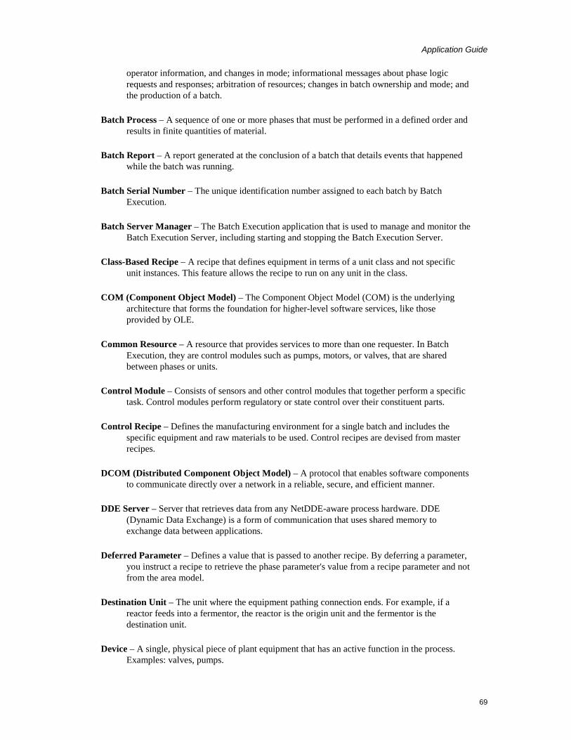
Application Guide
69
operator information, and changes in mode; informational messages about phase logic requests and responses; arbitration of resources; changes in batch ownership and mode; and the production of a batch.
Batch Process – A sequence of one or more phases that must be performed in a defined order and results in finite quantities of material.
Batch Report – A report generated at the conclusion of a batch that details events that happened while the batch was running.
Batch Serial Number – The unique identification number assigned to each batch by Batch Execution.
Batch Server Manager – The Batch Execution application that is used to manage and monitor the Batch Execution Server, including starting and stopping the Batch Execution Server.
Class-Based Recipe – A recipe that defines equipment in terms of a unit class and not specific unit instances. This feature allows the recipe to run on any unit in the class.
COM (Component Object Model) – The Component Object Model (COM) is the underlying architecture that forms the foundation for higher-level software services, like those provided by OLE.
Common Resource – A resource that provides services to more than one requester. In Batch Execution, they are control modules such as pumps, motors, or valves, that are shared between phases or units.
Control Module – Consists of sensors and other control modules that together perform a specific task. Control modules perform regulatory or state control over their constituent parts.
Control Recipe – Defines the manufacturing environment for a single batch and includes the specific equipment and raw materials to be used. Control recipes are devised from master recipes.
DCOM (Distributed Component Object Model) – A protocol that enables software components to communicate directly over a network in a reliable, secure, and efficient manner.
DDE Server – Server that retrieves data from any NetDDE-aware process hardware. DDE (Dynamic Data Exchange) is a form of communication that uses shared memory to exchange data between applications.
Deferred Parameter – Defines a value that is passed to another recipe. By deferring a parameter, you instruct a recipe to retrieve the phase parameter's value from a recipe parameter and not from the area model.
Destination Unit – The unit where the equipment pathing connection ends. For example, if a reactor feeds into a fermentor, the reactor is the origin unit and the fermentor is the destination unit.
Device – A single, physical piece of plant equipment that has an active function in the process. Examples: valves, pumps.

Application Guide
70
Dwell Time – The length of time a phase maintains a specific state. The dwell time is used by the Soft Phase Server.
Enumeration – A list of strings that can be referenced by their ordinal offset in a list. For example, Sunday=0, Monday=1, Tuesday=2.
Enumeration Set – A logical grouping of enumerations.
Equipment Database – See Area Model.
Equipment Editor – The Batch Execution application used to configure an area model.
Equipment ID – A unique ID that is assigned to all equipment configured in the Equipment Editor. This ID is used to acquire and release resources. It must match the equipment ID used by the phase logic in the process controller.
Equipment Module – Consists of equipment and control modules that together perform a minor processing task (a phase). In Batch Execution, phases are directly tied to the equipment modules on which they execute.
Equipment Capacity – The amount a unit can contain, transfer, or process. During Active Binding, Batch Execution ensures that the units allocated to unit procedures during batch production meet the minimum capacity requirement defined for the unit procedure.
Equipment Pathing – Connections drawn in the area model that determine the valid execution paths for a batch.
Equipment Phase – A phase that is part of the equipment control. The logic for an equipment phase resides in the process controller.
Equipment Phase Tags – The tags used to tie equipment phases to the equipment. In Batch Execution, you tie equipment phases to the equipment by specifying the equipment-specific addresses for ten standard tags plus any parameter, report, and request tags required by the phase. By specifying these tags, you are configuring a unit's equipment phase. These tags are required by the Phase Logic Interface (PLI). The PLI is programmed in the process controller and provides a standard interface between the Batch Execution Server and the equipment phase.
Event/log File – During operation, each Batch Execution Server maintains a historical record of the commands it received and the operations performed. Batch Execution stores this record as an event. Each event is identified by the batch serial number and the .EVT extension. These file resides in the Batch Execution Journals directory.
Failure ID – The ordinal associated with a string in the PHASE_FAILURES enumeration set.
Formula Parameter – See Recipe Parameters. The term Formal Parameter was replaced with Recipe Parameter in version 4.5 of the product.
Hold Propagation – The hold propagation controls how the Batch Execution Server responds when a phase fails. In general, when a phase fails, the phase's hold logic executes and the PLC sends a hold command to the Batch Execution Server. The Batch Execution Server

Application Guide
71
can ignore the hold command (no hold propagation) or can respond by holding: a phase, an operation, a unit procedure, or the entire batch procedure.
Jacobson Links – Connections that are drawn within a recipe's sequential function chart (SFC) to graphically represent a necessary physical connection between unit procedures.
Logical Data Model (LDM) – The table structures and rules that represent the storage of Batch Execution recipes, events, and electronic signatures in a relational database.
Loop – Defines the logic to repeat a series of steps multiple times.
Manifold Object – A control module that is used to connect multiple units as part of the area model's equipment pathing.
Manual Mode – A state associated with a step in a batch. When a step is in Manual mode, its transition does not execute until an operator sends a message instructing it to do so.
Master Recipe – A recipe that defines the equipment requirements to manufacture a product. This equipment is grouped into process cells. Control engineers design master recipes to run on many different lines within a process cell.
Maximum Owners – Identifies the maximum number of owners that can simultaneously own an equipment resource. It is used to arbitrate resources and typically is set to one to allow only one owner at a time.
O-Auto Mode – A state associated with a step in a batch. When a step is in O-Auto mode, its transition executes and an operator can send commands to its procedure.
OLE Object – A document, graphic, or other component from an application that supports Object Linking and Embedding (OLE). For example, an OLE object can be a Word document or Excel Spreadsheet. These OLE objects are created in one application and can be embedded into another application. In Batch Execution, OLE objects can be embedded into a project where they can be opened and edited from the Proficy iFIX WorkSpace.
OPC (OLE for Process Control) – Defines standard objects, methods, and properties for meeting interoperability requirements of real-time process automation applications.
OPC Item – A named data structure accessed through OPC using a request or advise.
OPC Server – An application that makes its data available to other applications using OPC. Batch Execution includes an OPC server for the iFIX process database.
Operation – An independent production activity within a unit procedure, consisting of phases and the algorithm necessary for the initiation, organization and control of those phases. There may be one or more phases within an operation that may execute sequentially or concurrently.
Operator Message – Identifies a string that is sent to the operator when the phase executes. The message ID must correspond with the ID used by the phase logic.
Operator Prompt – A phase parameter that prompts the operator for a value.

Application Guide
72
Or Structure – The logic for a decision you want a recipe to make. The result of the decision determines the path that the recipe executes.
Ordinal – Number used by the phase logic to represent an enumeration.
Origin Unit – The unit where the equipment pathing connection originated. For example, if a reactor feeds into a fermentor, the reactor is the origin unit and the fermentor is the destination unit.
P-Auto Mode – A state associated with a step in a batch. When a step is in P-Auto mode, its transition executes but an operator cannot send commands to its procedure.
Parallel Production – When two or more steps must be complete before the next step can execute.
Phase Link Group – A list of phases that communicate with each other.
Phase Logic – Automates the equipment in a plant. Contains the instructions to sequence the individual equipment connected to the physical devices. It is the code that contains the control steps such as opening a valve, starting a pump, or stopping a totalizer.
Phase Memory Variable – A named storage space that exists in the process controller's memory to store the values for 15 unique data items that the Batch Execution Server and the phase use to communicate.
Phase Message – Identifies a string that is sent to the operator when the phase executes. The message ID must correspond with the ID used by the phase logic.
Phase Parameter – Phase parameter are specified during the development of the area model.
Phase Parameter Array – Resides in the process controller and contains a number of elements that are referenced using an array index. Each element of a phase parameter array can contain one phase parameter value.
Phase Partners – The phases required for the selected phase to operate. Typically used to synchronize phases.
Phase Report – Reports that detail actual process values or batch values used by the equipment phase. This information is uploaded from the phase logic in the process controller to the Batch Execution Server after the phase completes.
PLI (Phase Logic Interface) – The interface between the Batch Execution Server and the phase logic. The PLI is the Batch Execution-specific portion of the phase and contains the state transition logic. It resides in the controller.
Primary Journal – The primary journal is located in the path where the Batch Execution Server first tries to write the event file. If the primary path is unavailable, the Batch Execution Server writes the event file to the secondary path.
Procedure – Defines a process strategy for making a batch. Procedures consist of unit procedures defined for a recipe.

Application Guide
73
Process – A sequence of chemical, physical, or biological activities for the conversion, transport, or storage of material or energy.
Process Cell – Consists of all the production and supporting equipment necessary to make a batch. It may include one or more production lines.
Process Cell with Fixed Path – A process cell in a network environment for which the path cannot be altered by an operator.
Process Cell with Variable Path – A process cell in a network environment for which the path is chosen by an operator when the batch is scheduled for production.
Process Stage – A part of a process that usually operates independently from other process stages and that usually results in a planned sequence of chemical or physical changes in the material being processed.
Production Report – A report generated at the conclusion of a batch that details events that happened while the batch was running.
Project – The entire set of elements needed to deliver a batch solution. These elements include the recipes, pictures, configuration files, and area model.
Proficy Batch Execution Archiver Manager – The Batch Execution application that is used to start and stop the Batch Execution Archiver.
Proficy Batch Execution Client – The graphical Batch Execution application used by the operator to monitor and control batches.
Proficy Batch Execution Server – The Batch Execution application that coordinates the function of your recipes, the area model, and each Batch Execution Client during production.
Proficy Batch Execution Service Configuration Utility – The Batch Execution utility that is used to configure the Batch Execution Server, Archiver, and EIB Server to run as Windows services.
Proficy Batch Execution WorkSpace – The application used to create and modify objects within a project.
Recipe – Defines the sequence of steps to produce a product.
Recipe Author – The individual responsible for creating a recipe.
Recipe Directory – The directory in which all recipe files are stored.
Recipe Editor – The Batch Execution application used to develop recipes.
Recipe Parameters – Variables used to control process values such as time, temperature, and quantities. Recipe parameters let you create flexible and reusable recipes.
Recipe Header – Administrative information about the recipe. This information includes the procedure identifier, version number, version date, and author.

Application Guide
74
Recipe Hierarchy – The S88.01 procedural model. This model defines procedures, unit procedures, and operations in a hierarchy of recipes. The Recipe Editor conforms to this model.
Recipe Management – The process of creating, maintaining and, if necessary, deleting recipes.
Report Parameter – Variables, defined in the area model, that represent process values from the PLC.
Request Tags – Functions that enable the phase logic to request the Batch Execution Server to perform specific actions, such as acquiring and releasing equipment and sending phase messages.
Resource – A single entity within the area model that is used in the production of a batch.
Resource Class – A logical grouping of common resources.
Restart Control – Controls how the Batch Execution Server, EIB, or Soft Phase Server starts. The restart mode can be:
Cold restart – Select Cold to always restart the server in cold restart mode. In cold restart mode, the Batch Execution Server provides an empty batch list.
Warm restart – Select Warm to always restart the server in warm restart mode. In warm restart mode, the Batch Execution Server restores the batch list and the state of the server to their last known state.
Prompt – Select Prompt (the default setting) to prompt users to select the restart mode: Warm or Cold.
SCADA Server – An iFIX server that communicates with process hardware and stores process values in a process database.
Scale Factor – A quantity that defines the percentage of a batch to be produced.
SCU (System Configuration Utility) – The SCU lets you configure the alarm routing, the network connections, the tasks that startup automatically, the SQL connections, and the SCADA and I/O driver settings.
SFC (Sequential Function Chart) – The graphical representation of a recipe.
Shared Resource – A resource shared between one or more process cells.
Single Step Mode – When a phase is set to single step mode, the phase transitions to the next programmed pause location and waits for the operator to issue a Resume command. The pause locations are preprogrammed into the phase logic. Typically, the phase logic is in single step mode when testing a phase.
Soft Phase Server – The Batch Execution application that handles the execution of soft phases.
Soft Phase – A PC-based phase that executes its phase logic via an executable program running

Application Guide
75
on a PC, or other non-controller device.
State – The condition of a piece of equipment or a procedural element at any given time. Possible states are Aborted, Aborting, Complete, Held, Holding, Idle, Ready, Restarting, Running, Stopping, and Stopped.
State Transition Logic – The logic within the PLI that provides a standard interface to the project-specific phase logic. The state transition logic receives commands from the Batch Execution Server or the operator and then initiates the different components of the project-specific phase logic. It resides in the controller.
Step Buffer – Used to store the previous value of the step index within the PLC.
Step Index – The current step of the active phase in the PLC.
Step Parameter – A parameter for a step defined in the recipe.
Tag – An individual I/O point in the PLC.
Tag Class – Defines common properties for a class of tags. Used to create class-based recipes.
Topic – The subdivision identifier within the DDE Application from which to retrieve information.
Transition – Defines when a recipe moves from one step to another in the sequential function chart.
UNC Paths – Microsoft's Universal Naming Convention (UNC) to access project files that are stored on other machines within your network. The syntax for UNC paths is as follows:
\\machinename\sharename\path\filename
Unit – A major piece of equipment in a process cell that performs a specific task. It consists of all the equipment and control modules that are needed to perform a task.
Unit Class – Defines common properties for a class of units. Used to create class-based recipes.
Unit Instance – A specific unit in a unit class, defined by the information that ties the equipment to the physical equipment.
Unit Priority – Indicates the priority of the unit, as compared to other units in the same unit class. If multiple units are available for a batch, Batch Execution selects the unit with the highest priority value. You can configure a UNIT_PRIORITY tag to determine the priority value for a unit or you can assign a static priority value to the unit in the area model configuration.
Unit Procedure – One or more operations that control the function of a single piece of equipment.
Unit Ready – Indicates whether the unit is ready for use. If the unit is not ready, Batch Execution cannot allocate the unit to a batch. You can configure a UNIT_READY tag to determine if the unit is ready, or you can configure the unit as "always ready" or "always not ready" in

Application Guide
76
the area model configuration.
Unit Tags – Tags that are associated with a unit, such as temperature and level tags. Unit tags are accessible to all phases that execute on that unit.
Unit Tag Class – A variable name assigned to a class of unit tags. Used in recipe transitions to implement class-based recipes.
VBEXEC.LOG – A list of errors that occurred during the production of a batch. In addition to being written to the log file, severe errors and warnings are sent to the SCADA node as alarms.
VBIS – A set of OLE Automation interfaces that allow 3rd party applications (Visual Basic, C++) to manipulate information from the Batch Execution Server, area model, and recipe database.
Watchdog – The name of an item in the DDE or OPC Server used by the Batch Execution Server and the respective data server to ensure a live communication connection between the two. The Batch Execution Server periodically writes a 1 to the watchdog and checks that the data server then writes a 0.

77
Index A
acknowledging prompts .................................... 43
Active Binding ................................................. 47
configuring in recipes ................................... 48
configuring in the area model ....................... 48
example ........................................................ 49
in sample application .................................... 37
understanding ............................................... 47
Active Journaling
architecture ................................................... 28
components of .............................................. 28
ActiveX controls ............................................... 44
BatchList control .......................................... 44
overview ......................................................... 7
using ............................................................. 44
alarms, viewing ................................................ 43
arbitrating resources ......................................... 43
architecture ......................................................... 4
client-server .................................................... 3
typical Batch Execution .................................. 4
archiver ............................................................. 28
configuring ................................................... 28
overview ....................................................... 28
archiving data ................................................... 58
area ................................................................... 11
in sample application ....................................34
level ..............................................................11
area model ........................................................11
configuring ...................................................34
configuring Active Binding in ......................48
configuring areas ..........................................34
configuring equipment phases ......................34
configuring process cells ..............................34
configuring unit classes ................................34
configuring unit instances .............................34
automatic binding .............................................48
B
Batch Execution ................................................. 4
benefits of using............................................. 3
Client ............................................................. 4
integrating ERP.............................................58
Server ............................................................. 4
system components ........................................ 4
Batch Execution archiver ..................................28
understanding................................................28
Batch Execution Client ...................................... 4
not using .......................................................57
operations tasks in ........................................40
overview ........................................................ 4
Batch Execution development workstation ....... 4

Application Guide
78
Batch Execution Server .................................... 22
communicating with ..................................... 33
performing supervisory control .................... 22
Batch Execution Soft Phase Server .................. 39
batch journal ..................................................... 43
viewing ......................................................... 43
batch operations ................................................ 40
task overview ................................................ 40
using iFIX ..................................................... 40
using the Batch Execution Client ................. 40
batches .............................................................. 41
adding to the Batch List ................................ 20
archiving event data ...................................... 58
controlling .................................................... 43
controlling with ActiveX controls ................ 44
controlling with VBIS .................................. 45
monitoring .................................................... 43
scheduling ..................................................... 20
states ............................................................. 42
understanding execution ............................... 41
C
campaign manager ............................................ 57
capacity ............................................................. 48
class-based design ............................................ 53
class-based recipes............................................ 37
implementing ................................................ 53
in sample application .................................... 37
client-server architecture .................................... 3
common resources ............................................14
defining control modules as ..........................14
control activity model .......................................22
defined ........................................................... 9
described .......................................................17
process control ..............................................22
process management .....................................21
production information management ............22
production planning & scheduling ................20
recipe management .......................................17
unit supervision.............................................22
control modules ................................................14
as common resources ....................................14
described .......................................................14
control recipe ....................................................24
creating .........................................................17
described .......................................................17
linking to the equipment ...............................24
control strategy .................................................25
designing .......................................................25
equipment requirements................................26
identifying the process flow ..........................25
outlining the general procedure ....................25
partitioning equipment ..................................25
controlling.........................................................43
batches ..........................................................43
phases ...........................................................43
custom applications ..........................................57

Index
79
campaign manager ........................................ 20
executing batches.......................................... 20
legacy system connection manager .............. 57
using VBIS to develop .................................. 57
D
demo project ....................................................... 9
designing a control strategy .............................. 25
developing ........................................................ 36
area model .................................................... 34
parameters .................................................... 36
pictures ......................................................... 40
projects ......................................................... 31
recipes ........................................................... 36
development tasks ............................................ 31
overview ....................................................... 31
E
Electronic documentation ................................... 1
embedding OLE documents ............................. 32
equipment ......................................................... 17
allocating to batches ..................................... 20
definition guidelines ..................................... 10
determining availability ................................ 20
linking to the control recipe .......................... 24
partitioning ................................................... 25
requirements for production ......................... 17
equipment capacity ........................................... 48
in Active Binding ......................................... 48
equipment hierarchy ......................................... 10
equipment module ............................................14
described .......................................................14
equipment pathing ............................................48
in Active Binding ..........................................48
equipment phase class ......................................14
defined ..........................................................14
sample configuration ....................................14
equipment phase instance .................................14
defined ..........................................................14
sample configuration ....................................14
equipment phases ..............................................34
in sample application ....................................34
understanding................................................34
equipment status ...............................................48
ERP system .......................................................58
integrating recipe data...................................17
integrating with .............................................58
examples ...........................................................54
Active Binding ..............................................49
class-based design .........................................53
equipment pathing ........................................49
phase synchronization ...................................54
sending and receiving phase messages .........54
F
forced bindings .................................................48
G
general procedure .............................................25
general recipe ....................................................17

Application Guide
80
H
header ............................................................... 17
I
IEC 1131-3 standard ........................................... 8
iFIX .................................................................... 4
Clients ............................................................. 4
HMI ................................................................ 5
integrating Batch Execution with ................... 5
pictures ......................................................... 40
SCADA .......................................................... 5
SCADA Servers.............................................. 4
iFIX database .................................................... 20
monitoring raw materials .............................. 20
iFIX pictures ..................................................... 40
operations tasks in ........................................ 40
integrating ........................................................... 4
Batch Execution with ERP ........................... 58
iFIX with Batch Execution ............................. 4
J
Jacobson Links ................................................. 48
defined .......................................................... 51
in Active Binding ......................................... 48
L
legacy system connection manager .................. 57
logical data model (LDM) ................................ 39
storing recipes in........................................... 39
M
master recipes
creating .........................................................17
minor processing task .......................................14
monitoring batches ...........................................43
O
OLE documents ................................................31
OPC ................................................................... 9
overview of .................................................... 9
operations .........................................................17
re-using .........................................................17
operator prompt ................................................48
P
P&ID diagram ..................................................25
parallel processing ............................................38
constructing SFCs for ...................................38
in sample application ....................................38
parameters.........................................................17
developing ....................................................37
in sample application ....................................37
recipe ............................................................17
phase logic ........................................................34
communicating with .....................................33
designing modular ........................................34
making requests from the Server ..................34
programming ................................................33
re-using .........................................................15
understanding................................................34
phase partners ...................................................54
synchronizing phases ....................................54

Index
81
phase reports ..................................................... 29
reporting process values ............................... 29
phase requests ................................................... 54
phases ............................................................... 54
controlling .................................................... 43
states ............................................................. 42
synchronizing ............................................... 54
physical model .................................................. 10
defined ............................................................ 9
objectives ...................................................... 10
piping and instrumentation diagram ................. 25
PLI .................................................................... 33
programming ................................................ 33
state transitions ............................................. 33
understanding ............................................... 33
procedural control model .................................. 15
defined ............................................................ 9
described ....................................................... 15
sample hierarchy ........................................... 15
procedure .......................................................... 17
described ....................................................... 17
process .............................................................. 23
action ............................................................ 23
control ........................................................... 22
described ....................................................... 23
management .................................................. 21
operation ....................................................... 23
stage .............................................................. 23
process cell .......................................................12
described .......................................................12
in sample application ....................................34
multiple-path .................................................12
multi-product, network path .........................12
network-path .................................................12
single-path ....................................................12
process controller, programming ......................33
process flow diagram ........................................25
process model ...................................................23
defined ........................................................... 9
described .......................................................23
process ..........................................................23
process action ...............................................23
process operation ..........................................23
process stage .................................................23
process parameters ............................................17
production information management ................22
production planning & scheduling ....................20
production schedule ..........................................20
Proficy Batch Execution WorkSpace ................ 6
developing projects .......................................31
overview ........................................................ 6
programming ....................................................33
phase logic ....................................................33
PLI ................................................................33
projects .............................................................39
area model ....................................................31

Application Guide
82
components of ................................................ 6
configuration files ......................................... 31
developing .................................................... 31
folders ........................................................... 31
OLE documents ............................................ 31
recipes ........................................................... 31
setting recipe storage type ............................ 39
prompting operators.......................................... 20
prompts, acknowledging ................................... 43
R
raw material, determining availability .............. 20
recipes ............................................................... 17
class-based .................................................... 17
components of .............................................. 17
configuring Active Binding in ...................... 48
control ........................................................... 17
developing .................................................... 36
equipment requirements ............................... 17
general .......................................................... 17
header ........................................................... 17
in sample application .................................... 37
levels of ........................................................ 17
managing ...................................................... 17
master ........................................................... 17
parameters .................................................... 17
procedure ...................................................... 17
releasing for production ................................ 17
site ................................................................ 17
storing in a relational database......................17
types ..............................................................17
relational database ............................................17
archiving data to ...........................................28
managing information ...................................22
storing recipes in ...........................................17
reports, developing custom ...............................29
requests, programming in phase logic ..............34
resources ...........................................................20
allocating to batches .....................................20
arbitrating .....................................................43
determining availability ................................20
re-using .............................................................17
operations .....................................................17
phase logic ....................................................15
unit procedures .............................................17
S
S88.01 ................................................................ 9
Batch Execution compliance ......................... 8
defined ........................................................... 9
equipment definition guidelines....................10
models............................................................ 9
objectives ....................................................... 9
S88.01 models ..................................................17
control activity ............................................... 9
physical .......................................................... 9
procedural control .......................................... 9
process ........................................................... 9
Index
83
recipe types ................................................... 17
sample application ............................................ 24
equipment requirements ............................... 26
general procedure ......................................... 25
P&ID diagram .............................................. 25
project items ................................................. 31
understanding ............................................... 24
scheduling batches ............................................ 20
servers ................................................................. 4
Batch Execution.............................................. 4
SFC
building recipes with ...................................... 8
constructing parallel processing ................... 38
SFC view screen ............................................... 43
site recipe .......................................................... 17
Soft Phase Server .............................................. 39
standards ............................................................. 8
state transition logic .......................................... 33
in PLI ............................................................ 33
synchronized phases ......................................... 54
described ....................................................... 54
T
testing your process ............................................ 4
U
unit .................................................................... 14
definition guidelines ..................................... 13
described .......................................................13
sample configuration ....................................13
sample equipment phase classes ...................14
unit classes ........................................................34
described .......................................................13
in sample application ....................................34
unit instances ....................................................34
described .......................................................13
in sample application ....................................34
unit priority .......................................................48
tag .................................................................48
unit procedure capacity .....................................48
unit ready ..........................................................48
units ..................................................................22
allocating to batches .....................................22
supervision of ...............................................22
V
VBIS .................................................................. 7
architecture overview of ................................ 7
campaign manager ........................................45
controlling batches ........................................45
determining raw material availability ...........20
developing custom applications ....................57
scheduling batches ........................................20
using to integrate data ...................................58