proficy* machine edition getting started v6fiona.dmcs.pl/~pkrasik/gfk-1868m.pdfgfk-1868m proficy*...
TRANSCRIPT

Proficy*
Machine EditionG E T T I N G S T A R T E D
V e r s i o n 6 . 0 0
J u n e 2 0 0 9
G F K - 1 8 6 8 M

All rights reserved. No part of this publication may be reproduced in any form or by any electronic or mechanical means, including photocopying and recording, without permission in writing from GE Fanuc Intelligent Platforms, Inc.
Disclaimer of Warranties and Liability
The information contained in this manual is believed to be accurate and reliable. However, GE Fanuc Intelligent Platforms, Inc. assumes no responsibilities for any errors, omissions or inaccuracies whatsoever. Without limiting the foregoing, GE Fanuc Intelligent Platforms, Inc. disclaims any and all warranties, expressed or implied, including the warranty of merchantability and fitness for a particular purpose, with respect to the information contained in this manual and the equipment or software described herein. The entire risk as to the quality and performance of such information, equipment and software, is upon the buyer or user. GE Fanuc Intelligent Platforms, Inc. shall not be liable for any damages, including special or consequential damages, arising out of the use of such information, equipment and software, even if GE Fanuc Intelligent Platforms, Inc. has been advised in advance of the possibility of such damages. The use of the information contained in the manual and the software described herein is subject to GE Fanuc Intelligent Platforms, Inc. standard license agreement, which must be executed by the buyer or user before the use of such information, equipment or software.
Notice
GE Fanuc Intelligent Platforms, Inc. reserves the right to make improvements to the products described in this publication at any time and without notice.
© 2009 GE Fanuc Intelligent Platforms, Inc. All rights reserved. * Trademark of GE Fanuc Intelligent Platforms, Inc. Any other trademarks referenced herein are used solely for purposes of identifying compatibility with the products of GE Fanuc Intelligent Platforms, Inc.
We want to hear from you. If you have any comments, questions, or suggestions about our documentation, send them to the following email address:
Contents
1 Contents i
2 Welcome 1System Requirements . . . . . . . . . . . . . . . . . . . . . . . . . . . . . . . . . . .2Installation . . . . . . . . . . . . . . . . . . . . . . . . . . . . . . . . . . . . . . . . . . .4Product Authorization . . . . . . . . . . . . . . . . . . . . . . . . . . . . . . . . . .5
Hardware Key Authorization . . . . . . . . . . . . . . . . . . . . . . . . . .5Software Key Authorization . . . . . . . . . . . . . . . . . . . . . . . . . . . .6
Contact GE Fanuc . . . . . . . . . . . . . . . . . . . . . . . . . . . . . . . . . . . . . .9General Contact Information . . . . . . . . . . . . . . . . . . . . . . . . . . .9Technical Support . . . . . . . . . . . . . . . . . . . . . . . . . . . . . . . . . . .9Americas . . . . . . . . . . . . . . . . . . . . . . . . . . . . . . . . . . . . . . . . . .9Europe, the Middle East, and Africa (EMEA) . . . . . . . . . . . . . . . .9Asia Pacific . . . . . . . . . . . . . . . . . . . . . . . . . . . . . . . . . . . . . . .10
3 Proficy* Machine Edition* 11Quick Start . . . . . . . . . . . . . . . . . . . . . . . . . . . . . . . . . . . . . . . . . .12Machine Edition Environment . . . . . . . . . . . . . . . . . . . . . . . . . . .14Getting to Know Machine Edition . . . . . . . . . . . . . . . . . . . . . . . . .15
Right-click, right-click, right-click . . . . . . . . . . . . . . . . . . . . . .15Getting Help . . . . . . . . . . . . . . . . . . . . . . . . . . . . . . . . . . . . . .15Accessing the Right Tool . . . . . . . . . . . . . . . . . . . . . . . . . . . . .17Using docking markers . . . . . . . . . . . . . . . . . . . . . . . . . . . . . .17Projects and the Navigator . . . . . . . . . . . . . . . . . . . . . . . . . . . .18Properties and the Inspector . . . . . . . . . . . . . . . . . . . . . . . . . .20Data Watch Lists . . . . . . . . . . . . . . . . . . . . . . . . . . . . . . . . . . .21Smart Lists . . . . . . . . . . . . . . . . . . . . . . . . . . . . . . . . . . . . . . . .22The Toolchest . . . . . . . . . . . . . . . . . . . . . . . . . . . . . . . . . . . . .23The Feedback Zone . . . . . . . . . . . . . . . . . . . . . . . . . . . . . . . . .24Managing Variables . . . . . . . . . . . . . . . . . . . . . . . . . . . . . . . . .25
Machine Edition Projects . . . . . . . . . . . . . . . . . . . . . . . . . . . . . . .27Sharing Projects between Machine Edition Workstations . . . . .27
Proficy* Machine Edition* 6.00 iGFK-1868M
C o n t e n t s
Running a Sample Project (View/Logic Developer - PC) . . . . . 28Developing a Machine Edition Project . . . . . . . . . . . . . . . . . . 30Validating and Downloading a Project . . . . . . . . . . . . . . . . . . 33Testing a View Project . . . . . . . . . . . . . . . . . . . . . . . . . . . . . . 35
4 Logic Developer - PC 37SFC Editor . . . . . . . . . . . . . . . . . . . . . . . . . . . . . . . . . . . . . . . . . . 39
Sequential Function Chart . . . . . . . . . . . . . . . . . . . . . . . . . . . . 39Working with the SFC editor - Offline . . . . . . . . . . . . . . . . . . . 40Working with the SFC editor - Online . . . . . . . . . . . . . . . . . . . 42
Ladder Editor . . . . . . . . . . . . . . . . . . . . . . . . . . . . . . . . . . . . . . . . 43Ladder Program . . . . . . . . . . . . . . . . . . . . . . . . . . . . . . . . . . . 43Working with the ladder editor - Offline . . . . . . . . . . . . . . . . . 44Working with the ladder editor - Online . . . . . . . . . . . . . . . . . 45
Instruction List Editor . . . . . . . . . . . . . . . . . . . . . . . . . . . . . . . . . . 47Instruction List . . . . . . . . . . . . . . . . . . . . . . . . . . . . . . . . . . . . 47Working with the IL editor - Offline . . . . . . . . . . . . . . . . . . . . 48Working with the IL editor - Online . . . . . . . . . . . . . . . . . . . . 49
Structured Text Editor . . . . . . . . . . . . . . . . . . . . . . . . . . . . . . . . . . 50Structured Text . . . . . . . . . . . . . . . . . . . . . . . . . . . . . . . . . . . . 50Working with the ST editor - Offline . . . . . . . . . . . . . . . . . . . . 51Working with the ST editor - Online . . . . . . . . . . . . . . . . . . . . 52
Function Block Diagram Editor . . . . . . . . . . . . . . . . . . . . . . . . . . 53Function Block Diagram . . . . . . . . . . . . . . . . . . . . . . . . . . . . . 53Working with the FBD editor - Offline . . . . . . . . . . . . . . . . . . 54Working with the FBD editor - Online . . . . . . . . . . . . . . . . . . 56
Logic Developer - PC Web Access . . . . . . . . . . . . . . . . . . . . . . . . 57Control I/O Drivers . . . . . . . . . . . . . . . . . . . . . . . . . . . . . . . . . . . 60
I/O Drivers . . . . . . . . . . . . . . . . . . . . . . . . . . . . . . . . . . . . . . . 60Control I/O Tool . . . . . . . . . . . . . . . . . . . . . . . . . . . . . . . . . . . 61Working with Control I/O . . . . . . . . . . . . . . . . . . . . . . . . . . . . 62
Controller . . . . . . . . . . . . . . . . . . . . . . . . . . . . . . . . . . . . . . . . . . . 63Working with the Controller . . . . . . . . . . . . . . . . . . . . . . . . . . 64
ii Proficy* Machine Edition* 6.00 GFK-1868M
C o n t e n t s
Warm Standby . . . . . . . . . . . . . . . . . . . . . . . . . . . . . . . . . . . . .65Working with Warm Standby . . . . . . . . . . . . . . . . . . . . . . . . .66Hot Standby . . . . . . . . . . . . . . . . . . . . . . . . . . . . . . . . . . . . . .67Working with Hot Standby . . . . . . . . . . . . . . . . . . . . . . . . . . .67OPC Servers, Warm Standby, and Hot Standby . . . . . . . . . . . .68
5 View* 69Panel Editor . . . . . . . . . . . . . . . . . . . . . . . . . . . . . . . . . . . . . . . . .70
Working with the Panel Editor . . . . . . . . . . . . . . . . . . . . . . . . .71Message Displays . . . . . . . . . . . . . . . . . . . . . . . . . . . . . . . . . .72
Script Editor . . . . . . . . . . . . . . . . . . . . . . . . . . . . . . . . . . . . . . . . .73Scripts . . . . . . . . . . . . . . . . . . . . . . . . . . . . . . . . . . . . . . . . . . .73Scripting Languages . . . . . . . . . . . . . . . . . . . . . . . . . . . . . . . . .74VBScript Syntax . . . . . . . . . . . . . . . . . . . . . . . . . . . . . . . . . . . .75Active Scripting Objects . . . . . . . . . . . . . . . . . . . . . . . . . . . . .75Working with the Script Editor . . . . . . . . . . . . . . . . . . . . . . . . .76
Grid Editors . . . . . . . . . . . . . . . . . . . . . . . . . . . . . . . . . . . . . . . . . .77Alarms . . . . . . . . . . . . . . . . . . . . . . . . . . . . . . . . . . . . . . . . . . . . .78
Alarm Groups . . . . . . . . . . . . . . . . . . . . . . . . . . . . . . . . . . . . .78Alarm Display Objects . . . . . . . . . . . . . . . . . . . . . . . . . . . . . .78
Logging data . . . . . . . . . . . . . . . . . . . . . . . . . . . . . . . . . . . . . . . . .80PLC Access I/O . . . . . . . . . . . . . . . . . . . . . . . . . . . . . . . . . . . . . . .81
Drivers . . . . . . . . . . . . . . . . . . . . . . . . . . . . . . . . . . . . . . . . . .81OPC . . . . . . . . . . . . . . . . . . . . . . . . . . . . . . . . . . . . . . . . . . . . . . .83
OPC Client . . . . . . . . . . . . . . . . . . . . . . . . . . . . . . . . . . . . . . .83Machine Edition OPC Servers . . . . . . . . . . . . . . . . . . . . . . . . .84
View Web Access . . . . . . . . . . . . . . . . . . . . . . . . . . . . . . . . . . . . .85Languages folder . . . . . . . . . . . . . . . . . . . . . . . . . . . . . . . . . . . . . .87
Working with the Languages editor . . . . . . . . . . . . . . . . . . . . .88View Runtime . . . . . . . . . . . . . . . . . . . . . . . . . . . . . . . . . . . . . . . .90
Networking . . . . . . . . . . . . . . . . . . . . . . . . . . . . . . . . . . . . . . .90QuickPanel Applications . . . . . . . . . . . . . . . . . . . . . . . . . . . . . . .92
External Keypad Assignment . . . . . . . . . . . . . . . . . . . . . . . . . .92
GFK-1868M Proficy* Machine Edition* 6.00 iiiGFK-1868M
C o n t e n t s
Scripts on QuickPanel Targets . . . . . . . . . . . . . . . . . . . . . . . . 93QPScript Language . . . . . . . . . . . . . . . . . . . . . . . . . . . . . . . . . 93
6 Motion Developer* 95About Motion Developer . . . . . . . . . . . . . . . . . . . . . . . . . . . . . . . 96
Supported motion control devices . . . . . . . . . . . . . . . . . . . . . 96Motion Applications . . . . . . . . . . . . . . . . . . . . . . . . . . . . . . . . . . . 97
Motion targets . . . . . . . . . . . . . . . . . . . . . . . . . . . . . . . . . . . . . 97Motion configuration . . . . . . . . . . . . . . . . . . . . . . . . . . . . . . . 98Motion programs . . . . . . . . . . . . . . . . . . . . . . . . . . . . . . . . . . 99Motion blocks . . . . . . . . . . . . . . . . . . . . . . . . . . . . . . . . . . . . 100
Motion Scripts . . . . . . . . . . . . . . . . . . . . . . . . . . . . . . . . . . . . . . 101Motion wizards . . . . . . . . . . . . . . . . . . . . . . . . . . . . . . . . . . . . . 102Special Wizards . . . . . . . . . . . . . . . . . . . . . . . . . . . . . . . . . . . . . 104
Application Builder flowchart editor . . . . . . . . . . . . . . . . . . . 104Motion Calculator . . . . . . . . . . . . . . . . . . . . . . . . . . . . . . . . . 106
CAM Profile Editor . . . . . . . . . . . . . . . . . . . . . . . . . . . . . . . . . . . 108
Index . . . . . . . . . . . . . . . . . . . . . . . . . . . . . . . . . . . . . . 111
iv Proficy* Machine Edition* 6.00 GFK-1868M
1
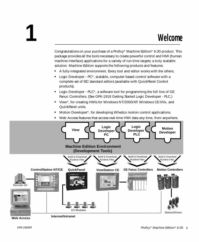
Proficy* Machine Edition* 6.00GFK-1868M1 WelcomeCongratulations on your purchase of a Proficy* Machine Edition* 6.00 product. This package provides all the tools necessary to create powerful control and HMI (human machine interface) applications for a variety of run-time targets; a truly scalable solution. Machine Edition supports the following products and features:■ A fully-integrated environment. Every tool and editor works with the others.■ Logic Developer - PC*, scalable, computer based control software with a
complete set of IEC standard editors (available with QuickPanel Control products).
■ Logic Developer - PLC*, a software tool for programming the full line of GE Fanuc Controllers. (See GFK-1918 Getting Started Logic Developer - PLC.)
■ View*, for creating HMIs for Windows NT/2000/XP, Windows CE II/IIx, and QuickPanel units.
■ Motion Developer*, for developing Whedco motion control applications.■ Web Access features that access real-time HMI data any time, from anywhere.
ControlStation NT/CE
Machine Edition Environment
Web Access
ViewStation CE
(Development Tools)Build & Download
Runtime FilesBuild & Download
Runtime Files
Internet/IntranetMotors/Drives
Build & DownloadRuntime Files
GE Fanuc Controllers
Remote I/O
View
Build & DownloadRuntime Files
LogicDeveloper
PC
LogicDeveloper
PLC
MotionDeveloper
I/O Modules
QuickPanel Motion Controllers
W e l c o m e
System Requirements1
S Y S T E M R E Q U I R E M E N T STo use Machine Edition and its tools, you require the following:
Deve lopment Env i ronment ■ Windows XP Professional Service Pack 2, Windows 2000 Professional Service Pack 4, or Windows Vista.
Note: Windows Vista SP1 is also supported, but Windows XP Tablet PC Edition and Windows XP Embedded are not supported.
■ Internet Explorer version 7.0, Internet Explorer version 6.0 Service Pack 1 or later, or Internet Explorer version 5.5 with Service Pack 2 Q810847 or later.
Note: You must install Internet Explorer before installing Machine Edition.■ TCP/IP Network protocol-based workstation (if you use an Ethernet
connection).■ Requirements for processor speed and memory are as follows:
Minimum: 1 GHz Pentium-based processor with 256 MB RAM
Recommended: 2 GHz Pentium-based processor with 512 MB RAM
Note: For projects with more than 75,000 variables or variable elements, at least 1 GB RAM is strongly recommended.
■ .NET Framework 2.0. If the Microsoft .NET Framework is not yet installed, it is automatically included during installation of Machine Edition.
■ 2 GB hard disk space for all the Machine Edition products and sample projects. Additional space is required for your projects and temporary files.
2 Proficy* Machine Edition* 6.00 GFK-1868M
W e l c o m eSystem Requirements
Windows NT/2000/XP Runt ime ■ Thin install for Logic Developer - PC and View Developer. Run-time executables are automatically updated from the development machine when the project is downloaded.
■ Windows XP Professional Service Pack 2, Windows XP Embedded, Windows 2000 Professional Service Pack 4, or Windows NT version 4.0 Service Pack 6a
Note: Windows Vista and Windows XP Tablet PC Edition are not supported.■ 233 MHz Pentium-based workstation (1.6 GHz recommended)
Note: 300 MHz is required for Windows 2000 or Windows XP Professional.■ 200 MB free hard disk space.■ 128 MB RAM (1 GB recommended; minimum 256 MB on XP).
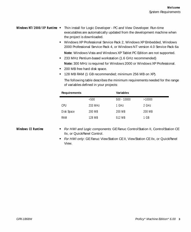
The following table describes the minimum requirements needed for the range of variables defined in your projects:
Windows CE Runt ime ■ For HMI and Logic components: GE Fanuc ControlStation II, ControlStation CE IIx, or QuickPanel Control.
■ For HMI only: GE Fanuc ViewStation CE II, ViewStation CE IIx, or QuickPanel View.
Requirements Variables
<500 500 - 10000 >10000
CPU 233 MHz 1 GHz 2 GHz
Disk Space 200 MB 200 MB 200 MB
RAM 128 MB 512 MB 1 GB
Proficy* Machine Edition* 6.00 3GFK-1868M
W e l c o m e
Installation1
I N S T A L L A T I O NFor last-minute information, release notes, and supported hardware lists for Machine Edition products, see the Important Product Information (IPI) document on the CD. There are several ways to view this document:
■ When installing Machine Edition, select Important Product Information on the initial Launcher screen.
■ From the Machine Edition Help menu, choose Important Product Information.
■ When running Machine Edition, click the InfoView tab in the Navigator, then double-click the Important Product Information page under Getting Started in the Table of Contents.
■ When running Machine Edition, click the Home button on the InfoViewer toolbar, then click the What’s New link under Get Started on the left hand side.
If you have any problems installing Machine Edition, please contact Technical Support (see page 9).
To i n s t a l l t h e f u l l Ma ch i n e E d i t i on d ev e l op m e n t e n v i r o nm e n t f r o m a CD1. Insert the Machine Edition CD into your CD-ROM drive.
Windows automatically starts the setup program. If the setup program does not automatically start, run Setup.exe in the root directory of the CD.
2. Click Install to start the install process.
3. Follow the instructions as they appear on the screen.
If a previous version of Machine Edition is installed on your workstation, you will be prompted to uninstall Machine Edition during the upgrade process. You should do so only when asked to by the installation process. Do not delete files left behind during uninstallation; these will be used by the new version.
T o i n s t a l l o n l y t he V i e w an d L og i c D e ve l o pe r - PC r u n t im e s f r om a C D1. Insert the Machine Edition CD into your CD-ROM drive.
If Windows automatically starts the setup program, cancel it by clicking Exit.
2. In a Windows Explorer window, navigate to the Install\Proficy Machine Edition Runtime Install\Disk1 folder on the Machine Edition CD.
3. Double-click the Setup.exe file in that folder.
4. Follow the instructions as they appear on the screen.
4 Proficy* Machine Edition* 6.00 GFK-1868M
W e l c o m eProduct Authorization
P R O D U C T A U T H O R I Z A T I O N
Before you can start developing projects in Machine Edition, you must authorize the software. If you do not do so, you have unrestricted use of the software features for only a short trial period. The authorization process takes only a few moments and enables you to take advantage of any product support for which you qualify.
There are two types of authorization available: software key authorization and hardware key authorization. Machine Edition products can use a mixture of authorization types on a single computer.
To see what products you are currently authorized for, on the Machine Edition Help menu, point to Product Authorization and then choose Authorize Software. This displays the Product Authorization dialog box. If you have a hardware key plugged in to a USB port, you can select the Show Hardware Keys check box to view the authorizations provided by that key.
H a r d w a r e K e y A u t h o r i z a t i o n
Hardware key authorization requires a special USB hardware key. This key contains internal settings that enable use of specific products, set by your dealer or retailer. Hardware keys can be used to authorize Machine Edition software only on the development side: if you need to authorize a Machine Edition run time, you must use a software key (see page 6).
Hardware key authorization is available only for Windows 2000, Windows XP, or Windows Vista and requires a free USB port on your computer.
To au t h o r i z e Ma c h i n e E d i t i o n p r od u c t s w i t h a h a r dwa r e k e y1. Locate a free USB port on your workstation.
Typically, the USB port is located on the front or back of your tower case, or in the side of a laptop computer. In some cases, a USB port can be found on your computer’s monitor.
2. Plug the hardware key into the USB port.
The first time you plug the key into a USB port, you will see a progress dialog box that indicates that Windows has detected new hardware and is updating its system settings. After the dialog box disappears, the settings stored in the hardware key are active and you can use the authorized Machine Edition products.
You must leave the hardware key in the port while using Machine Edition. If you remove the key from the port, authorization for those products vanishes, though you can still use products previously authorized using a software key.
Proficy* Machine Edition* 6.00 5GFK-1868M
W e l c o m e
Product Authorization1
To move authorization to another computer, remove the hardware key from the source computer and plug it into a USB port on the destination computer.
S o f t w a r e K e y A u t h o r i z a t i o n
When authorizing Machine Edition products with a software key, you need to contact us by telephone, fax, or e-mail. If you want to authorize your software by telephone, note that authorization personnel are available only during regular business hours (between 8 a.m. and 4 p.m. MST).
Software key authorization is specific to a single computer or workstation. If you want to work with Machine Edition on a different workstation, you must move the authorization to that second workstation (see page 7).
To a u t h o r i z e a c o py o f Ma ch i n e E d i t i o n w i t h a s o f t wa r e k ey1. Have your serial number(s) ready. The serial numbers can be found on the License Key sheet that came with your
product.
2. Run the Product Authorization program from the Start menu | Programs | GE Fanuc | Proficy Machine Edition | Product Authorization.
The Product Authorization dialog box appears.
3. Click Add.
4. Select the medium with which you are authorizing: Internet, Phone/Fax/E-mail or Floppy Disk Transfer. Click Next.
If you choose the Internet option, follow the instructions on the web site.
If you choose the Phone/ Fax/ Email option, proceed to step 5.
If you choose the Floppy Disk Transfer option, ensure you have an authorization disk to proceed.
5. Fill in the fields in the dialog box. Fields identified with an asterisk (*) must be filled in.
If authorizing online click Submit Authorization once the form is completed.
If authorizing via phone/fax, click the Phone/Fax button once the form is completed and call the number on the screen to receive a new key code(s).
If authorizing via e-mail, click the Send E-mail button once the form is complete.
■ Phone. Phone the number listed on the screen to receive a new key code(s).
■ Fax. Click Print FAX and fax the Product Authorization Request to us (our fax number will be on the print out). We will then reply by fax with your new key code(s).
■ Internet. From the Authorization web page, click Submit Authorization. We will then reply by e-mail with your new key code(s).
6 Proficy* Machine Edition* 6.00 GFK-1868M
W e l c o m eProduct Authorization
■ E-mail. Click Authorize to e-mail us. We will then reply by e-mail with your new key code(s).
Product Authorization is complete after you enter the new key code and it has been accepted. Depending on the product you have purchased, you may need to run the Product Authorization program a number of times. For example, if you bought ControlStation NT, you will need to authorize both Runtime and Development.
T o mo ve th e a u t ho r i z a t i o n t o a no t he r c om p u t e rYou can run the software only on the computer that the Product Authorization was run on. If you want to develop your projects on a different computer, you need to complete the following steps to move the authorization from one computer to another.
1. Install Machine Edition on the computer that the authorization will be moved to. Run the Product Authorization program from the Start menu | Programs | GE Fanuc | Proficy Machine Edition | Product Authorization.The Product Authorization dialog box appears.
2. Click Move and then click OK. There is a Target Site Code on the top right hand side of the screen. Write down this site code carefully. It must be accurate for the move to work. You will need the Target Site Code when you move the authorized software from the source computer.
3. Click Authorize by disk. At this point, you need to go to the source computer that has the authorized software, and move the authorization to a disk.
4. From the source computer, run the Product Authorization program.
5. Click Move, and then click OK.
6. Enter the Target Site Code that you wrote down from Step 3 and click Next. Verify that the site code is correct, and then click OK.
7. Insert a blank formatted floppy disk into the floppy drive and click Next. The authorization code will be moved to the disk and a dialog box should appear telling you it was successful. Click OK.
8. Go back to the computer to which you are moving the authorization and insert the floppy disk. The screen that is asking for an authorization disk is displayed. Click Next.
9. Click Finish. A screen appears telling you the move was successful. Click OK.The authorization has now been moved to the new computer.
Proficy* Machine Edition* 6.00 7GFK-1868M

W e l c o m e
Product Authorization1
To upg rade a s o f tw a r e k e y a u th o r i z a t i o n t o a ha r dwa re k e y a u t h o r i z a t i o n1. Order a hardware key.
Your software authorization remains valid until you complete the following steps.
2. When you receive the hardware key, locate a free USB port on your computer.
3. Plug the hardware key into the USB port.
8 Proficy* Machine Edition* 6.00 GFK-1868M

W e l c o m eContact GE Fanuc
C O N T A C T G E F A N U CIf you purchased this product through a GE Fanuc Authorized Channel Partner, please contact them directly.
G e n e r a l C o n t a c t I n f o r m a t i o n
Online Technical Support & GlobalCare: www.gefanuc.com/support
Comments about our manuals or online help: [email protected]
Additional information: www.gefanuc.com
T e c h n i c a l S u p p o r t
If you have technical problems that cannot be resolved with the information in this guide, please contact us by telephone or email, or on the web at www.gefanuc.com/support.
A m e r i c a sOnline Technical Support: www.gefanuc.com/supportPhone: 1-800-GE FANUC (1-800-433-2682)International Americas Direct Dial: 1-434-978-5100Technical Support Email: [email protected] Care Email: [email protected] language of support: English
E u r o p e , t h e M i d d l e E a s t , a n d A f r i c a ( E M E A )Online Technical Support: www.gefanuc.com/supportPhone: +800 1 GE FANUC (+800-1-433-2682)Technical Support Email: [email protected] Care Email: [email protected] languages of support: English, French, German, Italian, Czech
Proficy* Machine Edition* 6.00 9GFK-1868M

W e l c o m e
Contact GE Fanuc1
A s i a P a c i f i cOnline Technical Support: www.gefanuc.com/supportPhone: +86-400-820-8208
+86-21-3217-4826 (India, Indonesia, and Pakistan)Technical Support Email: [email protected] (China)
[email protected] (Japan)[email protected] (remaining Asia customers)
Customer Care Email: [email protected]
10 Proficy* Machine Edition* 6.00 GFK-1868M
2 Proficy* Machine Edition*Proficy* Machine Edition* offers you a complete solution for the development of automation applications under one roof. With Machine Edition’s integrated development environment and tools, you’ll spend more time building applications and less time learning the software.
Machine Edition products are fully integrated with the environment and with each other:
■ They share the same project database. No more wasted time synchronizing data points between applications!
■ They share the same set of tools, providing a consistent user interface throughout the development process.
■ They feature full drag-and-drop capabilities between tools and editors.
■ They feature a true scalable solution. You can choose what type of machine your projects are downloaded to and will run on.
The first part of this chapter provides an overview of the Machine Edition environment. The second part provides some key Machine Edition concepts you need to know before you begin. The third part shows how to open and explore some of the sample projects included with a new Machine Edition installation. When you’ve finished, you’ll have a solid foundation for building your own automation projects.
■ For more help getting started, in the InfoView tab of the Navigator, expand the Getting Started library.
Proficy* Machine Edition* 6.00 11GFK-1868M
P r o f i c y * M a c h i n e E d i t i o n *
Quick Start
1
2
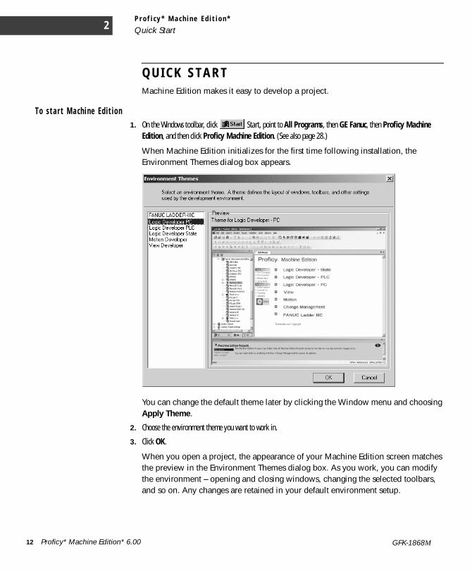
Q U I C K S T A R TMachine Edition makes it easy to develop a project.
T o s t a r t Ma ch i ne Ed i t i o n1. On the Windows toolbar, click Start, point to All Programs, then GE Fanuc, then Proficy Machine
Edition, and then click Proficy Machine Edition. (See also page 28.)
When Machine Edition initializes for the first time following installation, the Environment Themes dialog box appears.
You can change the default theme later by clicking the Window menu and choosing Apply Theme.
2. Choose the environment theme you want to work in.
3. Click OK.
When you open a project, the appearance of your Machine Edition screen matches the preview in the Environment Themes dialog box. As you work, you can modify the environment – opening and closing windows, changing the selected toolbars, and so on. Any changes are retained in your default environment setup.
2 Proficy* Machine Edition* 6.00 GFK-1868M
P r o f i c y * M a c h i n e E d i t i o n *Quick Start
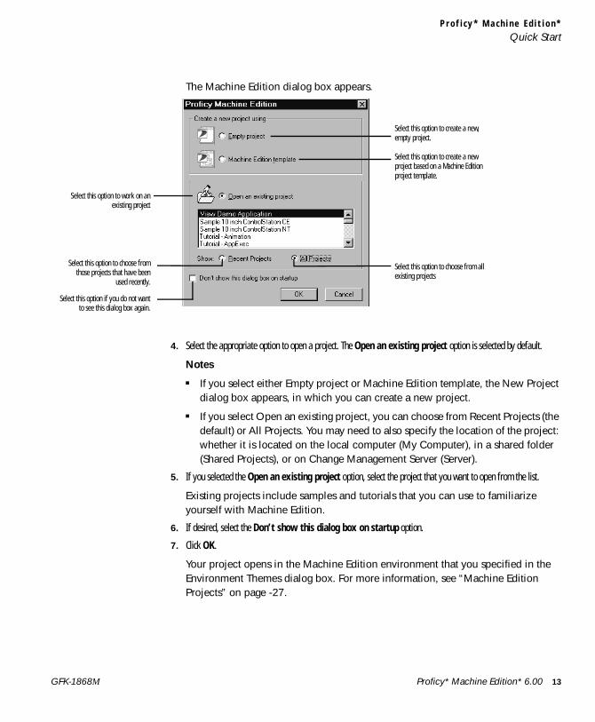
The Machine Edition dialog box appears.
4. Select the appropriate option to open a project. The Open an existing project option is selected by default.
Notes
■ If you select either Empty project or Machine Edition template, the New Project dialog box appears, in which you can create a new project.
■ If you select Open an existing project, you can choose from Recent Projects (the default) or All Projects. You may need to also specify the location of the project: whether it is located on the local computer (My Computer), in a shared folder (Shared Projects), or on Change Management Server (Server).
5. If you selected the Open an existing project option, select the project that you want to open from the list.
Existing projects include samples and tutorials that you can use to familiarize yourself with Machine Edition.
6. If desired, select the Don’t show this dialog box on startup option.
7. Click OK.
Your project opens in the Machine Edition environment that you specified in the Environment Themes dialog box. For more information, see “Machine Edition Projects” on page -27.
Select this option to work on anexisting project
Select this option to choose fromthose projects that have been
used recently.
Select this option if you do not wantto see this dialog box again.
Select this option to create a new, empty project.
Select this option to create a new project based on a Machine Edition project template.
Select this option to choose from all existing projects
Proficy* Machine Edition* 6.00 13GFK-1868M
P r o f i c y * M a c h i n e E d i t i o n *
Machine Edition Environment2
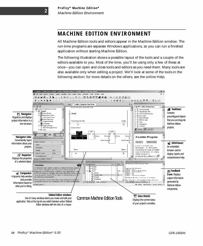
M A C H I N E E D I T I O N E N V I R O N M E N T All Machine Edition tools and editors appear in the Machine Edition window. The run-time programs are separate Windows applications, so you can run a finished application without starting Machine Edition.
The following illustration shows a possible layout of the tools and a couple of the editors available to you. Most of the time, you’ll be using only a few of these at once—you can open and close tools and editors as you need them. Many tools are also available only when editing a project. We’ll look at some of the tools in the following section; for more details on the others, see the online Help.
Inspector:Displays the properties
of a selected object.
Companion:A dynamic help window
that providesinformation based on
what you’re doing.
InfoViewer: An embedded browser used to display reports and comprehensive help.
Feedback Zone: Displays output information generated by Machine Edition components.
Tabbed Editor window:One of many windows where you create and edit your
application. Tabs at the top let you switch between active TabbedEditor windows with the click of a mouse.
Data Watch: Displays the current status of your project’s variables.
Navigator:Organizes and displaysproject information in a
tree structure.
Toolchest: Contains preconfigured objects that you can drag into Machine Edition projects.
Common Machine Edition Tools
Navigator tabs:Conveniently layers
information about yourprojects.
14 Proficy* Machine Edition* 6.00 GFK-1868M

P r o f i c y * M a c h i n e E d i t i o n *Getting to Know Machine Edition
G E T T I N G T O K N O W M A C H I N E E D I T I O NThe following are some key features of the Machine Edition environment. Knowing them will make your first few hours with Machine Edition a breeze.
R i g h t - c l i c k , r i g h t - c l i c k , r i g h t - c l i c k
No matter what object appears on your screen while using Machine Edition, you can right-click it to perform operations on it. In fact, this is probably the most common way you’ll get things done. Machine Edition tailors the menu of commands depending on the current status of your project.
G e t t i n g H e l p
There are many ways to access the Machine Edition online help system.
■ Press F1 on any selected item for context-sensitive help.
■ Browse through the table of contents in the InfoView tab of the Navigator.
■ Perform a full-text search of the help in a separate HTML Viewer window: on the Help menu, choose Search.
■ Search for keywords using the index: on the Help menu, choose Index.
■ Use the Companion to dynamically display a brief description about whatever item you have selected.
You can also access additional help on the web. In Machine Edition on the Help menu, point to GE Fanuc on the Web, and then choose:
■ Technical Advisor.
■ GE Fanuc Home Page.
Proficy* Machine Edition* 6.00 15GFK-1868M
P r o f i c y * M a c h i n e E d i t i o n *
Getting to Know Machine Edition2
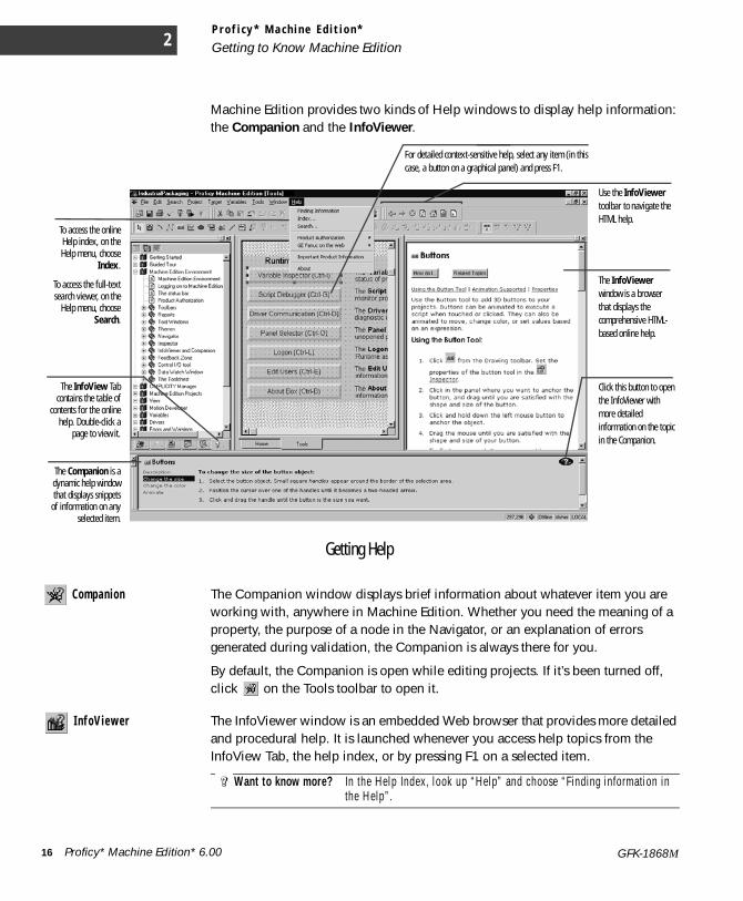
Machine Edition provides two kinds of Help windows to display help information: the Companion and the InfoViewer.
Compan ion The Companion window displays brief information about whatever item you are working with, anywhere in Machine Edition. Whether you need the meaning of a property, the purpose of a node in the Navigator, or an explanation of errors generated during validation, the Companion is always there for you.
By default, the Companion is open while editing projects. If it’s been turned off, click on the Tools toolbar to open it.
I n f oViewer The InfoViewer window is an embedded Web browser that provides more detailed and procedural help. It is launched whenever you access help topics from the InfoView Tab, the help index, or by pressing F1 on a selected item.
Want to know more? In the Help Index, look up “Help” and choose “Finding information in the Help”.
Getting Help
Click this button to open the InfoViewer with more detailed information on the topic in the Companion.
The InfoView Tabcontains the table of
contents for the onlinehelp. Double-click a
page to view it.
To access the onlineHelp index, on theHelp menu, choose
Index.
To access the full-textsearch viewer, on the
Help menu, chooseSearch.
For detailed context-sensitive help, select any item (in this case, a button on a graphical panel) and press F1.
The InfoViewer window is a browser that displays the comprehensive HTML-based online help.
The Companion is adynamic help windowthat displays snippets
of information on anyselected item.
Use the InfoViewer toolbar to navigate the HTML help.
16 Proficy* Machine Edition* 6.00 GFK-1868M
P r o f i c y * M a c h i n e E d i t i o n *Getting to Know Machine Edition
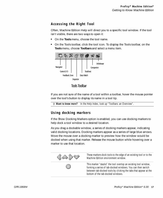
A c c e s s i n g t h e R i g h t T o o l
Often, Machine Edition Help will direct you to a specific tool window. If the tool isn't visible, there are two ways to open it:
■ On the Tools menu, choose the tool name.
■ On the Tools toolbar, click the tool icon. To display the Tools toolbar, on the Tools menu, choose Toolbars and select a menu item.
If you are not sure of the name of a tool within a toolbar, hover the mouse pointer over the tool’s button to display its name in a tool tip.
U s i n g d o c k i n g m a r k e r s
If the Show Docking Markers option is enabled, you can use docking markers to help dock a tool window to a desired location.
As you drag a dockable window, a series of docking markers appear, indicating valid docking locations. Docking markers appear as a series of large blue arrows. Move the mouse over a docking marker to preview how the window would be docked when using that marker. Release the mouse button while hovering over a marker to use that location.
Want to know more? In the Help Index, look up “Toolbars: an Overview”.
These markers dock tools to the edge of an existing tool or to the Machine Edition environment window.
This marker “stacks” the tool overtop an existing tool window, forming a series of tab-docked windows. You can then switch between tab-docked tools by clicking the tabs that appear at the bottom of the tab-docked windows.
InfoViewer
Companion
Toolchest
Inspector
Feedback Zone
Control I/O
Data Watch
Tools Toolbar
Navigator
Proficy* Machine Edition* 6.00 17GFK-1868M
P r o f i c y * M a c h i n e E d i t i o n *
Getting to Know Machine Edition2
P r o j e c t s a n d t h e N a v i g a t o r
Nav igato r The Navigator window organizes and manages your projects.
■ Use the Navigator to create and manage projects, add targets and components to your project, set your environment preferences, create scripts, open editors, create variables, and more.
■ The Navigator is organized into several tabs. The available tabs depend on which Machine Edition products are installed and whether a Machine Edition project is open. For example, the Project and Variables tabs appear only when a Machine Edition project is open.
■ Within each tab, items are displayed in a tree of nodes or folders. You can expand and collapse the tree, just like folders in Windows Explorer.
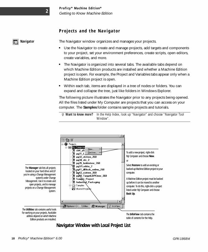
The following picture illustrates the Navigator prior to any projects being opened. All the files listed under My Computer are projects that you can access on your computer. The Samples folder contains sample projects and tutorials.
Want to know more? In the Help Index, look up “Navigator” and choose “Navigator Tool Window”.
The Manager tab lists all projectslocated on your hard drive and (if
you’re using a Change Managementsystem) under Change
Management. Use it to create andopen projects, and to manage
projects on a Change Managementsystem.
To add a new project, right-click My Computer and choose New.
or
Select Restore to add an existing or backed-up Machine Edition project to your computer.
A Machine Edition project must be backed up before it can be moved to another computer. To do this, right-click a project listed under My Computer and choose Back Up.
The InfoView tab contains the table of contents for the Help.
The Utilities tab contains useful toolsfor working on your projects. Available
utilities depend on which MachineEdition products are installed.
Navigator Window with Local Project List
18 Proficy* Machine Edition* 6.00 GFK-1868M
P r o f i c y * M a c h i n e E d i t i o n *Getting to Know Machine Edition
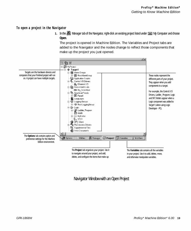
T o ope n a p r o j e c t i n t he Nav i ga t o r1. In the Manager tab of the Navigator, right-click an existing project listed under My Computer and choose
Open.The project is opened in Machine Edition. The Variables and Project tabs are added to the Navigator and the nodes change to reflect those components that make up the project you just opened.
The Options tab contains option andpreference settings for the Machine
Edition environment.
The Variables tab contains all the variables in your project. Use it to add, delete, move, and otherwise manipulate variables.
The Project tab organizes your project. Use it to navigate around your project, and add, delete, and configure the items that make up
These nodes represent the different parts of your project. They appear when you add components to a target.
For example, the Control I/O Drivers, Ladder_Program, Logic and SFC folders appear when a Logic component was added to Target1 (when using Logic Developer - PC).
Navigator Window with an Open Project
Targets are the hardware devices andcomputers that your finished project will run
on. A project can have multiple targets.
Proficy* Machine Edition* 6.00 19GFK-1868M
P r o f i c y * M a c h i n e E d i t i o n *
Getting to Know Machine Edition2
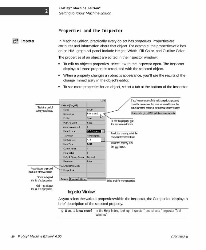
P r o p e r t i e s a n d t h e I n s p e c t o r
I nspec tor In Machine Edition, practically every object has properties. Properties are attributes and information about that object. For example, the properties of a box on an HMI graphical panel include Height, Width, Fill Color, and Outline Color.
The properties of an object are edited in the Inspector window:
■ To edit an object’s properties, select it with the Inspector open. The Inspector displays all those properties associated with the selected object.
■ When a property changes an object’s appearance, you’ll see the results of the change immediately in the object’s editor.
■ To see more properties for an object, select a tab at the bottom of the Inspector.
As you select the various properties within the Inspector, the Companion displays a brief description of the selected property.
Want to know more? In the Help Index, look up “Inspector” and choose “Inspector Tool Window”.
Properties are organizedmuch like Windows folders.
Click to expandthe list of subproperties.
Click to collapsethe list of subproperties.
This is the kind ofobject you selected.
To edit this property, click the button.
To edit this property, typethe new value in the box.
To edit this property, select the new value from the list box.
If you’re ever unsure of the valid range for a property, hover the mouse over its current value and look at the status bar at the bottom of the Machine Edition window.
Select a tab for more properties.
Inspector Window
20 Proficy* Machine Edition* 6.00 GFK-1868M
P r o f i c y * M a c h i n e E d i t i o n *Getting to Know Machine Edition
D a t a W a t c h L i s t s
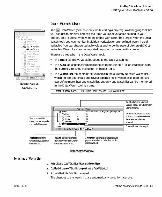
The Data Watch (available only while editing a project) is a debugging tool that you can use to monitor and edit real-time values of variables defined in your project. This is useful while working online with a run-time target. With the Data Watch tool, you can monitor individual variables or user-defined watch lists of variables. You can change variable values and force the state of discrete (BOOL) variables. Watch lists can be imported, exported, or saved with a project.
There are three tabs in the Data Watch tool:
■ The Static tab shows variables added to the Data Watch tool.
■ The Auto tab contains variables selected in the variable list or associated with the currently-selected instruction in ladder logic.
■ The Watch List tab contains all variables in the currently selected watch list. A watch list lets you create and save a separate list of variables to monitor. You can define more than one watch list, but only one watch list can be monitored in the Data Watch tool at a time.
To d e f i n e a Wa t c h L i s t :1. Right-click the Data Watch Lists folder and choose New.
2. Double-click the new Watch List to open it in the Data Watch tool.
3. Add variables to the Data Watch as desired.The changes to the watch list are automatically saved for later use.
Want to know more? In the Help Index, choose “Data Watch List”.
Navigator: Project tab
Data Watch nodes
A Watch List tab contains all variables in your project that have been added to the currently-selected Watch list.
The Static tab contains variables that you add to the Data Watch tool.
The Auto tab displays variables associated with the item currently selected in an editor or tool.
The structure variable Robot1 has been expanded to show all of its elements.
Double-click a value to change it.
The IEC or Reference address of variables mapped to I/O terminals or Controller memory.
The name and value of each element of the structure variable Robot1 is shown here, even when not expanded.
Data Watch Window
Proficy* Machine Edition* 6.00 21GFK-1868M
P r o f i c y * M a c h i n e E d i t i o n *
Getting to Know Machine Edition2
S m a r t L i s t s
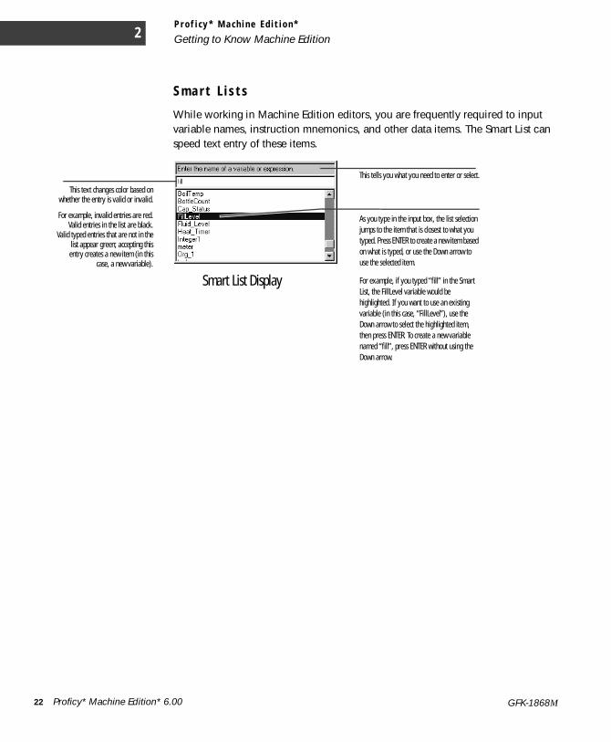
While working in Machine Edition editors, you are frequently required to input variable names, instruction mnemonics, and other data items. The Smart List can speed text entry of these items.
As you type in the input box, the list selection jumps to the item that is closest to what you typed. Press ENTER to create a new item based on what is typed, or use the Down arrow to use the selected item.
For example, if you typed “fill” in the Smart List, the FillLevel variable would be highlighted. If you want to use an existing variable (in this case, “FillLevel”), use the Down arrow to select the highlighted item, then press ENTER. To create a new variable named “fill”, press ENTER without using the Down arrow.
This text changes color based onwhether the entry is valid or invalid.
For example, invalid entries are red.Valid entries in the list are black.
Valid typed entries that are not in thelist appear green; accepting thisentry creates a new item (in this
case, a new variable).
This tells you what you need to enter or select.
Smart List Display
22 Proficy* Machine Edition* 6.00 GFK-1868M
P r o f i c y * M a c h i n e E d i t i o n *Getting to Know Machine Edition
T h e T o o l c h e s t
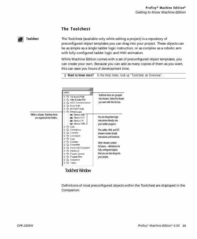
Too l ches t The Toolchest (available only while editing a project) is a repository of preconfigured object templates you can drag into your project. These objects can be as simple as a single ladder logic instruction, or as complex as a robotic arm with fully-configured ladder logic and HMI animation.
While Machine Edition comes with a set of preconfigured object templates, you can create your own. Because you can add as many copies of them as you want, this can save you hours of development time.
Definitions of most preconfigured objects within the Toolchest are displayed in the Companion.
Want to know more? In the Help Index, look up ”Toolchest: an Overview”.
Within a drawer, Toolchest itemsare organized into folders. You can drag these logic
instructions directly into your ladder program.
The Ladder, HMI, and SFC drawers contain simple instructions and functions.
Other drawers contain fxClasses—definitions for fully-configured objects that you can also drag into your project.
Toolchest items are grouped into drawers. Select the drawer you want with this list box.
Toolchest Window
Proficy* Machine Edition* 6.00 23GFK-1868M
P r o f i c y * M a c h i n e E d i t i o n *
Getting to Know Machine Edition
24
2
T h e F e e d b a c k Z o n e
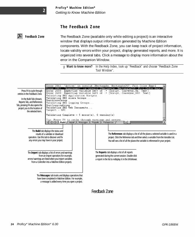
Feedba ck Zone The Feedback Zone (available only while editing a project) is an interactive window that displays output information generated by Machine Edition components. With the Feedback Zone, you can keep track of project information, locate validity errors within your project, display generated reports, and more. It is organized into several tabs. Click a message to display more information about the error in the Companion Window.
Want to know more? In the Help Index, look up “Feedback” and choose “Feedback Zone Tool Window”.
Feedback Zone
The Build tab displays the status andresults of a validate or download
operation. Use this tab to discover and fixany errors you may have in your project.
The References tab displays a list of all the places a selected variable is used in a project. Click the Reference tab and then select a variable from the Variable List. You will see a list of all the places the variable is referenced in your project.
The Reports tab displays a list of all reports generated during the current session. Double-click a report in the list to redisplay it in the InfoViewer.
The Messages tab tracks and displays operations thathave been completed in Machine Edition. For example,
a message is added every time you open a project.
Press F4 to cycle throughentries in the Feedback Zone.
In the Build Tab (shown),Reports Tab, and References
Tab, pressing F4 also opens theproject you to the location of
the selected item..
The Import tab displays a list of errors and warningsfrom an import operation (for example,
errors/warnings are listed when you import variablesfrom a Controller into a Machine Edition project).
Proficy* Machine Edition* 6.00 GFK-1868M

P r o f i c y * M a c h i n e E d i t i o n *Getting to Know Machine Edition
M a n a g i n g V a r i a b l e s
Variables are named storage spaces for data values defined in Machine Edition projects. A variable could store the current velocity of a motion Controller motor, the height of a robotic arm, or any other value that an application needs to keep track of. Most variables in a project can be shared among various components and targets, such as View panels and Logic Developer - PC’s ladder logic.
You manage variables in the Variables tab of the Navigator, also named the Variable List. Like most items in Machine Edition, you configure variables by editing their properties in the Inspector.
The values a variable can store depends on its data type. For example, a DINT data type indicates that the variable can store “Double Integers”, 32-bit values. The location where a variable’s value is stored is indicated by its data source. Typically, a variable’s value is either stored internally in the target’s memory or is retrieved (and sent) to external Controller hardware, via an I/O terminal or other connection. Available data types and data sources depend on the target type and (if applicable) components added to the target.
You can also use arrays and structure data types in Machine Edition projects. An array is a series of variable elements with identical data types, referenced by a 0-based index (as in “MyArray[3]”). A structure data type is a group of variable elements that may or may not have the same data type, referenced by the name of each element (as in “MyStructure.MyElement”). Custom structure data types are created with fxClasses in the Toolchest.
Proper ty Co l umns In addition to the Inspector, with the three buttons at the top of the Navigator, you can edit variable properties in a spreadsheet-like column view.
Want to know more? In the Help Index, look up “STRUCTURE data types”.
Click to open and close the property column display. This button is available only in the Variables tab.
Click to dock and undock the Navigator window. Undocking the Navigator (that is, making it work likean Editor window) can make it easier to work with properties in the column view.
Click to display a list of available property columns. Double-click a property to add it to the current set.
Proficy* Machine Edition* 6.00 25GFK-1868M
P r o f i c y * M a c h i n e E d i t i o n *
Getting to Know Machine Edition2
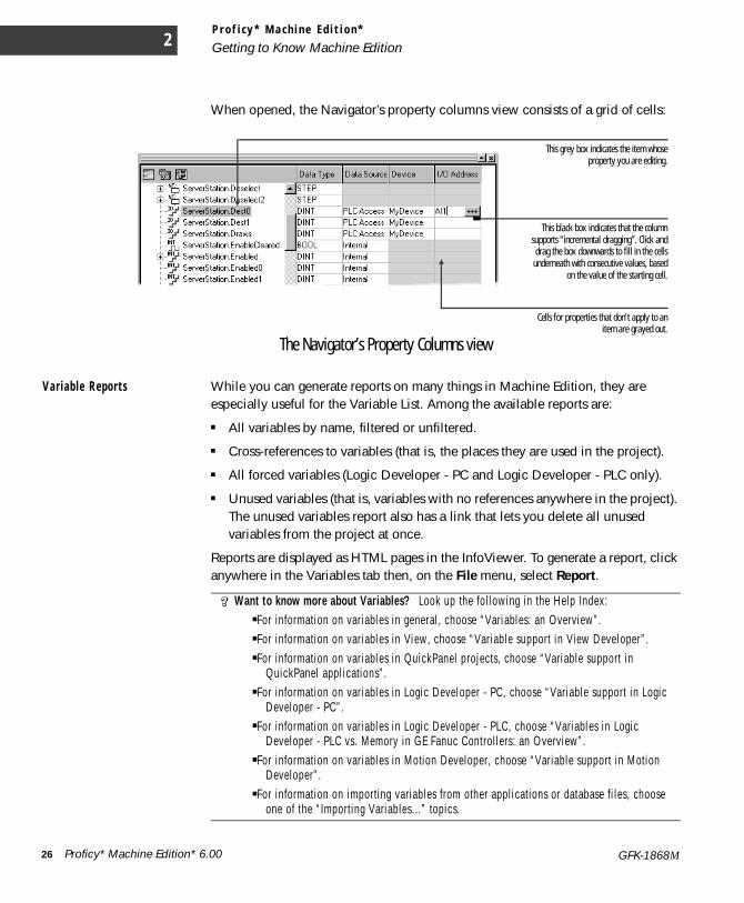
When opened, the Navigator’s property columns view consists of a grid of cells:
Var i ab l e Repor t s While you can generate reports on many things in Machine Edition, they are especially useful for the Variable List. Among the available reports are:
■ All variables by name, filtered or unfiltered.
■ Cross-references to variables (that is, the places they are used in the project).
■ All forced variables (Logic Developer - PC and Logic Developer - PLC only).
■ Unused variables (that is, variables with no references anywhere in the project). The unused variables report also has a link that lets you delete all unused variables from the project at once.
Reports are displayed as HTML pages in the InfoViewer. To generate a report, click anywhere in the Variables tab then, on the File menu, select Report.
Want to know more about Variables? Look up the following in the Help Index:■For information on variables in general, choose “Variables: an Overview”.■For information on variables in View, choose “Variable support in View Developer”.■For information on variables in QuickPanel projects, choose “Variable support in
QuickPanel applications”.■For information on variables in Logic Developer - PC, choose “Variable support in Logic
Developer - PC”.■For information on variables in Logic Developer - PLC, choose “Variables in Logic
Developer - PLC vs. Memory in GE Fanuc Controllers: an Overview”.■For information on variables in Motion Developer, choose “Variable support in Motion
Developer”.■For information on importing variables from other applications or database fi les, choose
one of the “Importing Variables...” topics.
This black box indicates that the columnsupports “incremental dragging”. Click anddrag the box downwards to fill in the cells
underneath with consecutive values, basedon the value of the starting cell.
Cells for properties that don’t apply to anitem are grayed out.
This grey box indicates the item whoseproperty you are editing.
The Navigator’s Property Columns view
26 Proficy* Machine Edition* 6.00 GFK-1868M
P r o f i c y * M a c h i n e E d i t i o n *Machine Edition Projects
M A C H I N E E D I T I O N P R O J E C T SDuring development, your automation application is named a project. Each Machine Edition project is made up of targets and (sometimes) components. A target represents the hardware platform where the finished project runs, such as a Windows XP computer, a Windows CE unit, a motion Controller, or a QuickPanel unit. Different Machine Edition products support different target types. Targets are often further subdivided into models, such as the ViewStation and ControlStation versions of Windows CE targets. Components add specific capabilities to a target. Available components depend on the target type, model, and what Machine Edition products you have installed.
For example, with View, you can you add an HMI component to Windows NT/2000/XP and Windows CE targets, used for creating human-machine interfaces. With Logic Developer - PC, you can add a Logic component to Windows NT/2000/XP and Windows CE targets. You can then create ladder logic to make a PC act as a Controller. View-only Windows CE targets do not support logic; therefore, you cannot download a project that contains logic to one.
With Motion Developer, you can program motion Controllers from your PC. Each motion device programmed by Motion Developer is represented by a separate Motion target. Because motion targets have no additional capabilities, they do not require adding components.
S h a r i n g P r o j e c t s b e t w e e n M a c h i n e E d i t i o n W o r k s t a t i o n s
If your site has multiple Machine Edition workstations connected through a network, you can use the Shared Projects folder to work on the same set of projects. Projects under the Shared Projects folder are stored in a directory you specify, typically a shared directory on the network.
No access or version control is applied to the Shared Projects folder. If multiple users open the same project at the same time, some changes may be lost.
Note: Shared Projects and Shared Variables are two completely different and separate features. For information on Shared Variables (which implement proxy variables between targets in different projects), see “PLC Access I/O” on page -81.
Want to know more? In the Help Index, look up “projects” and choose “Machine Edition Projects: an Overview”.
Want to know more? In the Help Index, look up “Shared Projects”.
Proficy* Machine Edition* 6.00 27GFK-1868M
P r o f i c y * M a c h i n e E d i t i o n *
Machine Edition Projects2
R u n n i n g a S a m p l e P r o j e c t ( V i e w / L o g i c D e v e l o p e r - P C )
If you’re using View or Logic Developer - PC, we’ve provided some sample projects that show basic operations of Machine Edition. Take a few minutes to complete the following steps and learn the basics of project development in Machine Edition.■ For a more detailed example of creating projects, in the Help Index, look up
“Tutorial” and choose one of the topics listed there.
T o r un a s am p l e p r o j e c t1. Run Machine Edition from the Start menu | All Programs | GE Fanuc | Proficy Machine Edition | Proficy Machine
Edition.
2. In the Manager tab of the Navigator, double-click one of the sample applications listed under the My Computer folder.
Sample applications include the following:
■ Alarm Trends: an HMI application that demonstrates alarms and charts.
■ Animation Features: an HMI application that depicts the various types of animation available in View.
■ Brewery: an HMI and logic brewery application that runs on a Windows NT target.
■ Car Wash: an HMI and logic application that runs on a Windows NT target. This application is built in an SFC document.
■ ControlStation HMI Features: an HMI and logic application that runs on a Windows NT target. This application also shows some web documents.
■ FC2000 Brewery: an HMI and logic brewery application that runs on a ControlStation/ViewStation CE II. (Projects containing a logic component cannot be downloaded to a ViewStation, as ViewStation CEs do not support logic.)
■ FC2000 Zone Control: an HMI and logic application that runs on a ControlStation/ViewStation CE II. This application runs a four-zone ventilation logic system. It is to be used with the ControlStation/ViewStation CE II Tutorial. (Because ViewStation CE targets do not support logic, projects with a logic component cannot be downloaded to a ViewStation.)
■ ST - Lunar Lander: an HMI and logic application that runs on a Windows NT target. This project demonstrates the Structured Text (ST) language and its interaction with UDFBs (User Defined Function Blocks).
Tutorials include
28 Proficy* Machine Edition* 6.00 GFK-1868M
P r o f i c y * M a c h i n e E d i t i o n *Machine Edition Projects
■ Animation: an HMI application that illustrates and provides details on the various animations that you can use in your HMI.
■ AppExec: an HMI application that demonstrates the AppExec Script function.
■ Keystrokes: an HMI application that displays the analog values associated with the keys on your keyboard.
■ Logging: an HMI application that demonstrates how to log production data to an ASCII text file.
■ Recipes: an HMI application that shows how one would load and modify recipes.
■ Scripting: an HMI application that demonstrates some of View’s scripting capabilities.
3. Browse through the project in Machine Edition.Open the project’s graphical panels, ladder logic, and SFCs (if they exist) in their respective editors. To open an editor, right-click the appropriate node in the
Project tab of the Navigator and choose Open.
Also, take a look at the properties of the various nodes and objects. To view an object’s properties, open the Inspector window, and then select an object.
4. In the newly opened project, press F9 to validate, download, and run the sample application.The F9 key is a shortcut for the Run command which automatically starts View Runtime and the Controller.
The sample application should now be running in both View Runtime and the Controller. View Runtime appears, displaying the first panel of the project’s HMI. You can see the real-time status of the logic by going online to the Controller.
T o go on l i n e t o t he Co n t r o l l e rIf you have chosen a project that contains logic and/or an SFC document, you can go online to the application and watch the logic being executed.
1. Minimize the Runtime window (but don’t close it) and return to Machine Edition.
2. In the Project tab of the Navigator, right-click the Target node and choose Go Online.You are now online to the Controller; that is, you are working with the application while it is running. The Controller is the part of the Runtime that solves logic and SFCs.
3. In the Project tab of the Navigator, open the Ladder Editor by double-clicking the Ladder Program node or open the SFC Editor by double-clicking the SFC node.In the editor, you can watch the logic being solved as the Controller operates. To start and stop Runtime and the Controller, right-click the target, point to Online
Proficy* Machine Edition* 6.00 29GFK-1868M
P r o f i c y * M a c h i n e E d i t i o n *
Machine Edition Projects2
Commands, and then click Start/Stop Runtimes. To go offline from the Controller, right-click the target, and then click Go Offline.
D e v e l o p i n g a M a c h i n e E d i t i o n P r o j e c t
The first thing to decide when you create a Machine Edition project is where the project will run after it is developed. That is, on what type of target hardware it will run.
For View and Logic Developer - PC, targets can be a Windows NT/2000/XP computer (either the one you’re developing the project on, or a remote one that you connect to through a network), or a Windows CE unit (a ControlStation/ViewStation CE II, CE IIx, or QuickPanel View/Control).
For View alone, your target can also be a conventional QuickPanel unit.
For Logic Developer - PLC and Logic Developer - State, your target is a GE Fanuc PACSystems Controller, Series 90 Controller, or VersaMax Controller. You can also configure remote I/O targets that represent a variety of remote I/O adapters and their associated I/O modules. See GFK-1918 Getting Started Logic Developer - PLC.
If you’re using Motion Developer, the choice is easy—determine whether your motion hardware is a motion Controller/drive or a drive-only device (see page 97).
After you’ve decided on the target, you need to determine which components your project will include: HMI (with View) and/or Logic (with Logic Developer - PC). Note that ViewStations do not support Logic components. A project can have multiple targets of different types with various components running on each target. In some cases, targets can be converted from one type to another. For example, you can convert a Windows NT target to and from a QuickPanel View target.
To c r e a t e a nd d eve l o p a p r o j e c tThe following procedure introduces the general steps involved in creating a project using a template, and downloading a project to a target computer.
1. Start Machine Edition from the Start menu | All Programs | GE Fanuc | Proficy Machine Edition | Proficy Machine Edition.
2. Create a project using a template.In the Manager tab of the Navigator, right-click My Computer and choose New. The New Project dialog box appears.
Want to know more? In the Help Index, look up “Targets: an Overview”.
30 Proficy* Machine Edition* 6.00 GFK-1868M

P r o f i c y * M a c h i n e E d i t i o n *Machine Edition Projects
If you’re using shared projects, you can also add new projects under the Shared Projects folder. Or, if you are working on a Change Management system, you can add new projects to the Machine Edition folder under the Server.
3. In the New Project dialog box, enter a name for the new project, select a template, and then click OK. A description of the template appears below your selection. You can click hypertext links in the description for details on the template components.
At this point, you need to know the type of target hardware to which your project will download, as this will determine which template you choose. In some project templates (such as the “View/Control” template), you can select this as one of several parameters within an HTML page on the template dialog box.
The project is opened in Machine Edition and the Navigator changes to reflect those components that make up the project you just created.
4. In the Variable List, create variables for your application.In the Variables tab of the Navigator, right-click the Variable List node, point to New Variable, and choose the type of variable you want to create.By default, the Variable List node filters out all system variables. System variables are created automatically when you add components to Windows NT, CE, QuickPanel, or GE Fanuc Controller targets. To display all variables including system variables, right-click the Variable List node, point to Filter By, and choose No Filter.
5. Create your application.With Logic Developer - PC, add logic (Ladder, FBD, IL, ST, SFC) to your project, and then configure a control I/O driver to model your hardware. If the template you chose did not include a Logic component, add one now—right-click the target, point to Add Component, and choose Logic. (View-only targets don’t support logic.)
■ In the Project tab of the Navigator, under the Logic folder, open the Ladder Editor by double-clicking the Ladder Program node.
■ Drag ladder instructions from the Toolchest into the editor. You can find ladder instructions in the PC Ladder Instructions drawer of the Toolchest.
■ Assign variables to instructions. You can do this with the Smart List, which appears when you insert or double-click an instruction. Or, drag a variable from
Want to know more? In the Help Index, look up “templates” and choose “Creating a New Machine Edition Project” or “Creating a new project under a Change Management system”.
Want to know more? In the Help Index, look up “Variables: an Overview”.
Proficy* Machine Edition* 6.00 31GFK-1868M

P r o f i c y * M a c h i n e E d i t i o n *
Machine Edition Projects2
the Variables tab of the Navigator and drop it on the instruction you want it mapped to.
■ You can add additional logic blocks (ladder subroutines, FBD, IL, ST) and organize your logic with SFC.
With View, you can create the graphical panels and animation for your project. If the template you chose did not include an HMI component, then add one now—right-click the target, point to Add Component, and choose HMI. (If a target has both an HMI and a Logic component, you’ll typically create the Logic component first.)■ In the Project tab of the Navigator, open the Panel Editor by double-clicking
a Panel node.■ Use the Graphical Panel toolbar to create your HMI and/or drag graphical
objects from the Toolchest onto a panel. You can find a set of fully-configured objects (complete with animation) in various Toolchest View Expert Objects drawers.
With Motion Developer, begin by running the Motion Expert wizard.
■ If necessary, open the “Main Wizard” home page by right-clicking the Motion target and choosing Main Wizard.
■ In the wizard page, click Motion Expert and follow the instructions on screen. For more information on using wizards, see page 102.
6. If necessary, configure the I/O hardware connections for your project.
■ For Logic Developer - PC, set up Control I/O in the Control I/O Drivers folder (in the Project tab of the Navigator). To add a driver, right-click the Control I/O Drivers folder and choose New Driver. Use the Control I/O tool to configure your drivers. Map variables to I/O terminals.
■ For View, set up PLC Access I/O in the PLC Access Drivers folder. To add a driver, expand the PLC Access Drivers folder, right-click View Native Drivers, and click New Driver. Configure the drivers in the Inspector window. On NT targets, you may want to set up OPC I/O in the OPC Client folder.
7. When your project is complete; validate, download, and run your project by pressing the F9 function key.Machine Edition saves the project, performs a validation, builds the run-time files, and attempts to establish a connection to the target computer.
Want to know more? In the Help Index, look up “Ladder Instructions: an Overview (PC)”.
Want to know more? In the Help Index, look up “Control I /O Tool: an Overview”.
32 Proficy* Machine Edition* 6.00 GFK-1868M

P r o f i c y * M a c h i n e E d i t i o n *Machine Edition Projects
V a l i d a t i n g a n d D o w n l o a d i n g a P r o j e c t
During project development, you will go through the validation and download processes several times. The validation process checks the project for errors. If the project contains errors, they are listed in the Build tab of the Feedback Zone.
■ All errors must be fixed before the download process can proceed. Warnings are also listed in the Feedback Zone, but they do not prevent the download from starting.
When fixing project errors, use the F4 function key to scroll through errors in the Feedback Zone, jumping to their locations in the project.
The download process involves two steps. The first step creates (or “builds”) all the run-time files necessary for a target to perform its role in a completed project. The second step downloads those files to the target devices or computers.
■ For Motion Developer, the easiest way to set up the motion control device for downloading is with the Set Communication Parameters wizard. Open the Main Wizard page for the target (right-click the target and select Main Wizard). Then, point to Target Configuration and click Communication Parameters. Click Finish when you’re done.
■ To download a View or Logic Developer - PC project to the Windows NT computer on which you are developing (a local target), ensure that the target property Computer Address is set to “.” (without the quotation marks). Otherwise—for remote targets—enter the IP address or computer name of the remote computer you want to download to, in the Computer Address property.
■ To download a QuickPanel project, ensure that the target property Computer Download Port is set to the applicable COM port.
Additional basic information on setting up Windows NT and CE targets follows.
Pr epa r i n g a Remo t e NT ta r g e t f o r D own l o ad i n gThe following steps need to be completed on a remote Windows NT target computer before you can download a project to it.
1. If you are downloading to another NT computer (other than the ControlStation or Windows CE unit), ensure that the run-time files are installed on that device.ViewStation and ControlStation targets are shipped with the run-time files preinstalled. If you’re using your own Windows NT computer, you’ll have to install the run-time files yourself from the Machine Edition installation CD (see page 4).
2. Share the Machine Edition installation directory with the development computer that contains the project files.
Proficy* Machine Edition* 6.00 33GFK-1868M
P r o f i c y * M a c h i n e E d i t i o n *
Machine Edition Projects2
In the Windows NT/2000/XP Explorer, navigate to the Proficy Machine Edition folder, right-click it and choose Sharing. Click Shared As and in the Share Name field, enter Proficy Machine Edition.
3. Ensure you have the proper permissions to download files to the target computer.Start the Windows NT User Manager. From the Taskbar, click Start, point to Programs, then to Administrative Tools, and click User Manager. Double-click the Guest user in the top half of the display. Clear the Account Disabled check box. In Windows 2000, open the Control Panel, click Administrative Tools, and then click Computer Management. Expand “System Tools” and then expand “Local Users and Groups”.
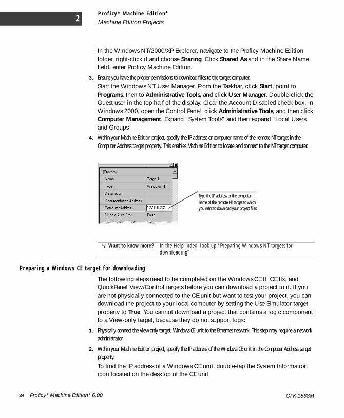
4. Within your Machine Edition project, specify the IP address or computer name of the remote NT target in the Computer Address target property. This enables Machine Edition to locate and connect to the NT target computer.
Pr epa r i n g a W i n dows C E t a r g e t f o r d o wn l oa d i ngThe following steps need to be completed on the Windows CE II, CE IIx, and QuickPanel View/Control targets before you can download a project to it. If you are not physically connected to the CE unit but want to test your project, you can download the project to your local computer by setting the Use Simulator target property to True. You cannot download a project that contains a logic component to a View-only target, because they do not support logic.
1. Physically connect the View-only target, Windows CE unit to the Ethernet network. This step may require a network administrator.
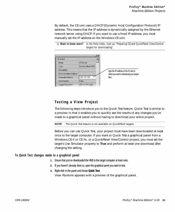
2. Within your Machine Edition project, specify the IP address of the Windows CE unit in the Computer Address target property.To find the IP address of a Windows CE unit, double-tap the System Information icon located on the desktop of the CE unit.
Want to know more? In the Help Index, look up “Preparing Windows NT targets for downloading”.
Type the IP address or the computer name of the remote NT target to which you want to download your project files.
34 Proficy* Machine Edition* 6.00 GFK-1868M
P r o f i c y * M a c h i n e E d i t i o n *Machine Edition Projects
By default, the CE unit uses a DHCP (Dynamic Host Configuration Protocol) IP address. This means that the IP address is dynamically assigned by the Ethernet network server using DHCP. If you want to use a fixed IP address, you must manually set the IP address on the Windows CE unit.
T e s t i n g a V i e w P r o j e c t
The following steps introduce you to the Quick Test feature. Quick Test is similar to a preview in that it enables you to quickly see the results of any changes you’ve made to a graphical panel without having to download your entire project.
NOTE The Quick Test feature is not available on QuickPanel targets.
Before you can use Quick Test, your project must have been downloaded at least once to the target computer. If you want to Quick Test a graphical panel from a Windows CE II or CE IIx, or a QuickPanel View/Control project, you must set the target’s Use Simulator property to True and perform at least one download after changing the setting.
To Qu i c k T e s t c han ge s made to a g r aph i c a l p a n e l1. Ensure that you’ve downloaded the HMI to the target computer at least once.
2. If you haven’t already done so, open the graphical panel you want to test.
3. Right-click in the panel and choose Quick Test. View Runtime appears with a preview of the graphical panel.
Want to know more? In the Help Index, look up “Preparing CE and QuickPanel View/Control targets for downloading”.
Type the IP address of the CE unit to which you want to download your project files.
Proficy* Machine Edition* 6.00 35GFK-1868M

L o g i c D e v e l o p e r - P C
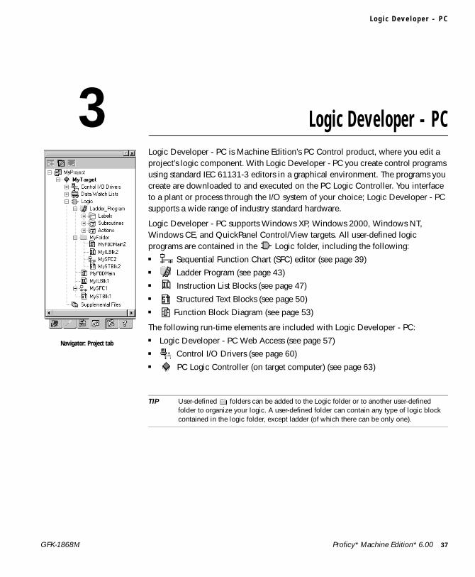
3 Logic Developer - PCLogic Developer - PC is Machine Edition’s PC Control product, where you edit a project’s logic component. With Logic Developer - PC you create control programs using standard IEC 61131-3 editors in a graphical environment. The programs you create are downloaded to and executed on the PC Logic Controller. You interface to a plant or process through the I/O system of your choice; Logic Developer - PC supports a wide range of industry standard hardware.
Logic Developer - PC supports Windows XP, Windows 2000, Windows NT, Windows CE, and QuickPanel Control/View targets. All user-defined logic programs are contained in the Logic folder, including the following: ■ Sequential Function Chart (SFC) editor (see page 39)■ Ladder Program (see page 43)■ Instruction List Blocks (see page 47)■ Structured Text Blocks (see page 50)■ Function Block Diagram (see page 53)
The following run-time elements are included with Logic Developer - PC:■ Logic Developer - PC Web Access (see page 57)■ Control I/O Drivers (see page 60)■ PC Logic Controller (on target computer) (see page 63)
TIP User-defined folders can be added to the Logic folder or to another user-defined folder to organize your logic. A user-defined folder can contain any type of logic block contained in the logic folder, except ladder (of which there can be only one).
Navigator: Project tab
Proficy* Machine Edition* 6.00 37GFK-1868M

L o g i c D e v e l o p e r - P C3
T o c r e a t e a p r o j e c t t ha t i n c l u d e s a l o g i c c om p on e n t1. In the Manager tab of the Navigator, right-click My Computer and choose New.
The New Project dialog box appears.
2. In the Project Name box, enter a name for your project.
3. From the Project Template list, choose a template that includes a logic component.A preview of what each template includes is displayed as you select different templates.
4. Click OK.Your new project is created and the Project tab opens in the Navigator.
To add a l o g i c c ompon en t t o a n ex i s t i n g p r o j e c t• In the Project tab of the Navigator, right-click a target, point to Add Component and click Logic.
The Logic folder with an empty ladder program and SFC component is added to your project.
To add a u s e r - d e f i n ed f o l d e r t o yo u r p r o j e c t1. Ensure that your project contains a logic component (see above).
2. Right-click the Logic folder or a user-defined folder, point to New, and click Folder.The new folder appears in the Project tab of the Navigator in alphabetical order.
3. (Optional.) Enter a name for the new folder.
38 Proficy* Machine Edition* 6.00 GFK-1868M
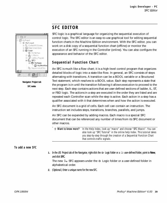
L o g i c D e v e l o p e r - P CSFC Editor
S F C E D I T O RSFC logic is a graphical language for organizing the sequential execution of control logic. The SFC editor is an easy-to-use graphical tool for editing sequential function charts in the Machine Edition environment. With the SFC editor, you can work on a disk copy of a sequential function chart (offline) or monitor the execution of an SFC running in the Controller (online). You can also configure the appearance and behavior of the SFC editor.
S e q u e n t i a l F u n c t i o n C h a r t
An SFC is much like a flow chart; it is a high-level control program that organizes detailed blocks of logic into a state-like flow. In general, an SFC consists of steps alternating with transitions. A transition can be a BOOL variable or a Structured Text statement, which resolves to a BOOL value. Each step represents a state that the program is in until the transition following it allows execution to proceed to the next step. Each step contains actions that are user-defined sections of ladder, IL, ST, or FBD logic. The actions in a step are executed in the order they are listed and are repeated each Controller scan while the step is active. Each action in a step has a qualifier associated with it that determines when and how the action is executed.
An SFC document is a grid of cells. Each cell can contain an instruction. The instruction set includes steps, transitions, branches, parallels, and jumps.
An SFC can be expanded by adding macros. Each macro is a special SFC document that can be referenced any number of times from its SFC document or other macros.
To add a n e w SF C1. In the Project tab of the Navigator, right-click the Logic folder or a user-defined folder, point to New,
and click SFC.The new SFC appears under the Logic folder or a user-defined folder in alphabetical order.
2. (Optional.) Enter a unique name for the new SFC.
Want to know more? In the Help Index, look up “macro” and choose “SFC Macro”. You can also look up “SFC Tutorial” in the online help Index. This tutorial takes you step-by-step through the creation of a Sequential Function Chart that controls traffic signals.
Navigator: Project tab
SFC nodes
Proficy* Machine Edition* 6.00 39GFK-1868M
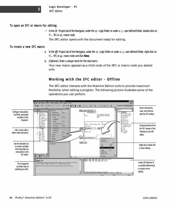
L o g i c D e v e l o p e r - P C
SFC Editor3
T o ope n a n S FC o r m a c r o f o r e d i t i ng• In the Project tab of the Navigator, under the Logic folder or under a user-defined folder, double-click an
SFC or macro node.The SFC editor opens with the document ready for editing.
T o c r e a t e a n e w SF C m a c r o1. In the Project tab of the Navigator, under the Logic folder or under a user-defined folder, right-click an
SFC or macro node and click New.
2. (Optional.) Enter a unique name for the new macro.Your new macro appears as a child node of the SFC or macro node you started with.
W o r k i n g w i t h t h e S F C e d i t o r - O f f l i n e
The SFC editor interacts with the Machine Edition tools to provide maximum flexibility when editing a program. The following picture illustrates some of the operations you can perform.
Use the Variable Listto create variablesthen drag them toinstructions in the
SFC editor.
Configure instructionsand their associated
variables in theInspector.
The Companionprovides help on
anything you click.
Insert instructions, rows, and columns with the SFC toolbar.
Drag instructions from the SFC drawer of the Toolchest to the SFC editor.
Right-click a blank cell to start editing.
Call a macro with aMacro Step instruction.
Locate all instances of a variable (References) or syntax errors (Build).
40 Proficy* Machine Edition* 6.00 GFK-1868M
L o g i c D e v e l o p e r - P CSFC Editor
To i n s e r t a n SF C i n s t r u c t i o n1. In the SFC editor, right-click a blank cell and click Place Instruction.
2. Choose an instruction mnemonic from the smart list that appears and press ENTER to finish.You can set the SFC editor options to automatically assign default variables to instructions or to let you choose and create your own.
T o Q u i c k E d i t a n S FC• In the SFC editor, click a blank cell and type instruction mnemonics separated by operators (see the following table).
Press ENTER to finish.Each mnemonic specifies one or more instructions. Each operator moves the location of the currently selected cell. Default variables are assigned when Quick Editing an SFC.
SFC Ope rato rs
To ... Use ...
move right one cell +
move left one cell -move down one cell ;stay on current cell /
Proficy* Machine Edition* 6.00 41GFK-1868M
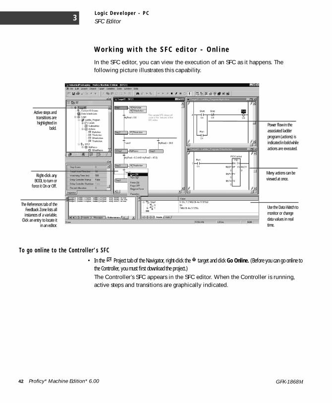
L o g i c D e v e l o p e r - P C
SFC Editor3
W o r k i n g w i t h t h e S F C e d i t o r - O n l i n e
In the SFC editor, you can view the execution of an SFC as it happens. The following picture illustrates this capability.
T o go on l i n e t o t he Co n t r o l l e r ’ s S F C• In the Project tab of the Navigator, right-click the target and click Go Online. (Before you can go online to
the Controller, you must first download the project.) The Controller’s SFC appears in the SFC editor. When the Controller is running, active steps and transitions are graphically indicated.
Active steps andtransitions arehighlighted in
bold.
Right-click anyBOOL to turn or
force it On or Off.
Power flow in the associated ladder program (actions) is indicated in bold while actions are executed.
Use the Data Watch to monitor or change data values in real time.
The References tab of theFeedback Zone lists allinstances of a variable.
Click an entry to locate itin an editor.
Many actions can be viewed at once.
42 Proficy* Machine Edition* 6.00 GFK-1868M
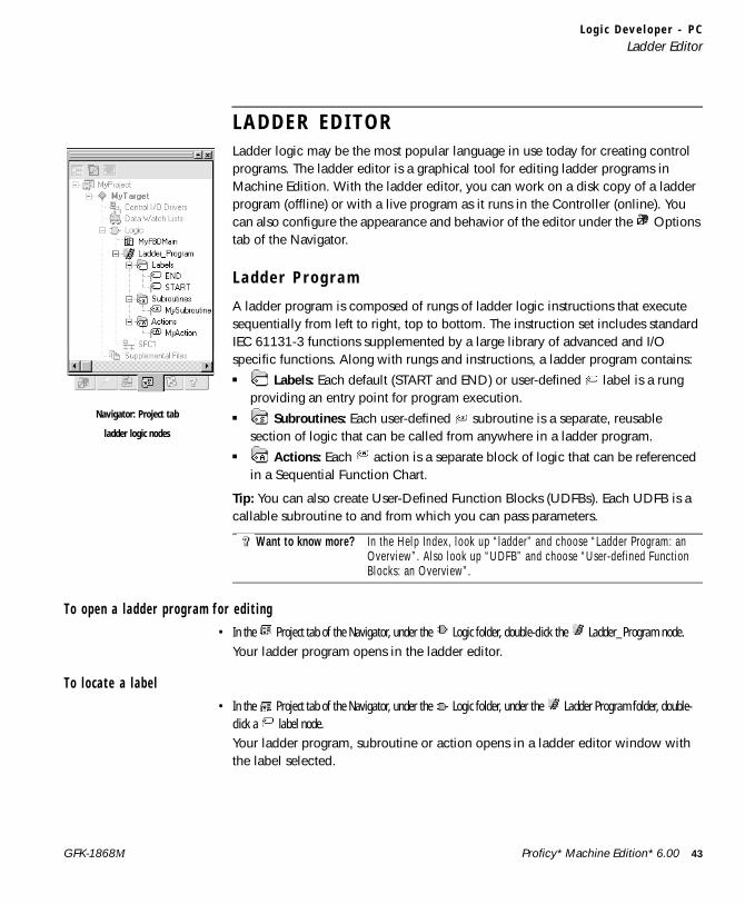
L o g i c D e v e l o p e r - P CLadder Editor
L A D D E R E D I T O RLadder logic may be the most popular language in use today for creating control programs. The ladder editor is a graphical tool for editing ladder programs in Machine Edition. With the ladder editor, you can work on a disk copy of a ladder program (offline) or with a live program as it runs in the Controller (online). You can also configure the appearance and behavior of the editor under the Options tab of the Navigator.
L a d d e r P r o g r a m
A ladder program is composed of rungs of ladder logic instructions that execute sequentially from left to right, top to bottom. The instruction set includes standard IEC 61131-3 functions supplemented by a large library of advanced and I/O specific functions. Along with rungs and instructions, a ladder program contains:■ Labels: Each default (START and END) or user-defined label is a rung
providing an entry point for program execution.■ Subroutines: Each user-defined subroutine is a separate, reusable
section of logic that can be called from anywhere in a ladder program.■ Actions: Each action is a separate block of logic that can be referenced
in a Sequential Function Chart.
Tip: You can also create User-Defined Function Blocks (UDFBs). Each UDFB is a callable subroutine to and from which you can pass parameters.
T o ope n a l a d d e r p r og r am f o r e d i t i n g• In the Project tab of the Navigator, under the Logic folder, double-click the Ladder_Program node.
Your ladder program opens in the ladder editor.
T o l o c a te a l a b e l• In the Project tab of the Navigator, under the Logic folder, under the Ladder Program folder, double-
click a label node.Your ladder program, subroutine or action opens in a ladder editor window with the label selected.
Want to know more? In the Help Index, look up “ladder” and choose “Ladder Program: an Overview”. Also look up “UDFB” and choose “User-defined Function Blocks: an Overview”.
Navigator: Project tab
ladder logic nodes
Proficy* Machine Edition* 6.00 43GFK-1868M
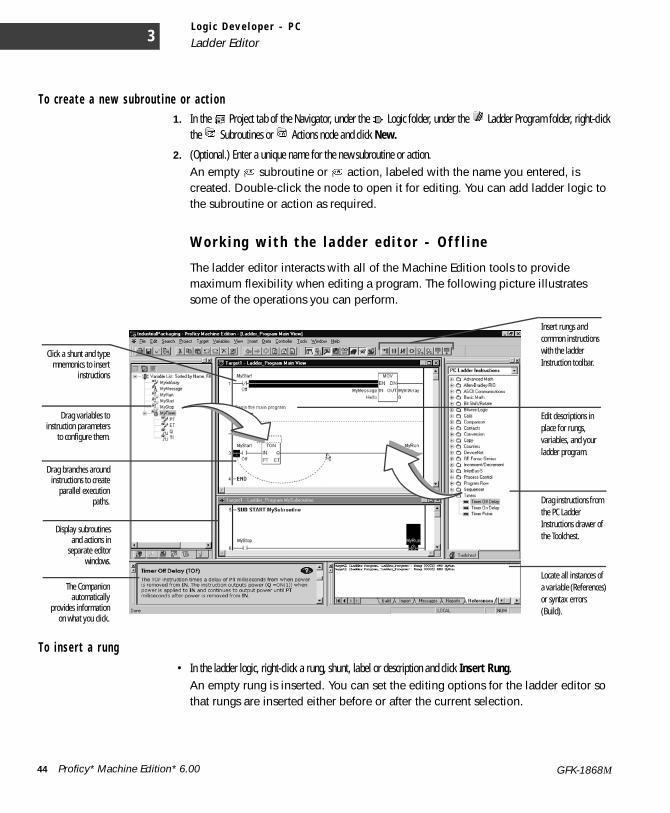
L o g i c D e v e l o p e r - P C
Ladder Editor3
T o c r e a t e a n e w su b rou t i n e o r a c t i o n1. In the Project tab of the Navigator, under the Logic folder, under the Ladder Program folder, right-click
the Subroutines or Actions node and click New.
2. (Optional.) Enter a unique name for the new subroutine or action.An empty subroutine or action, labeled with the name you entered, is created. Double-click the node to open it for editing. You can add ladder logic to the subroutine or action as required.
W o r k i n g w i t h t h e l a d d e r e d i t o r - O f f l i n e
The ladder editor interacts with all of the Machine Edition tools to provide maximum flexibility when editing a program. The following picture illustrates some of the operations you can perform.
T o i n s e r t a r u ng• In the ladder logic, right-click a rung, shunt, label or description and click Insert Rung.
An empty rung is inserted. You can set the editing options for the ladder editor so that rungs are inserted either before or after the current selection.
Drag instructions from the PC Ladder Instructions drawer of the Toolchest.
The Companionautomatically
provides informationon what you click.
Drag variables toinstruction parameters
to configure them.
Drag branches aroundinstructions to create
parallel executionpaths.
Insert rungs and common instructions with the ladder Instruction toolbar.
Click a shunt and typemnemonics to insert
instructions
Edit descriptions in place for rungs, variables, and your ladder program.
Locate all instances of a variable (References) or syntax errors (Build).
Display subroutinesand actions in
separate editorwindows.
44 Proficy* Machine Edition* 6.00 GFK-1868M
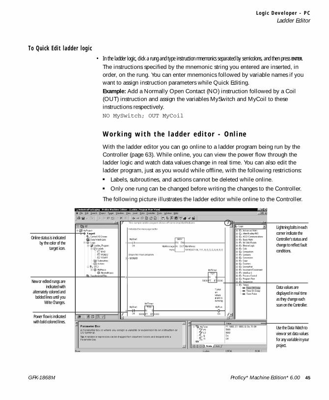
L o g i c D e v e l o p e r - P CLadder Editor
T o Q u i c k E d i t l a d de r l o g i c• In the ladder logic, click a rung and type instruction mnemonics separated by semicolons, and then press ENTER.
The instructions specified by the mnemonic string you entered are inserted, in order, on the rung. You can enter mnemonics followed by variable names if you want to assign instruction parameters while Quick Editing.Example: Add a Normally Open Contact (NO) instruction followed by a Coil (OUT) instruction and assign the variables MySwitch and MyCoil to these instructions respectively.NO MySwitch; OUT MyCoil
W o r k i n g w i t h t h e l a d d e r e d i t o r - O n l i n e
With the ladder editor you can go online to a ladder program being run by the Controller (page 63). While online, you can view the power flow through the ladder logic and watch data values change in real time. You can also edit the ladder program, just as you would while offline, with the following restrictions:■ Labels, subroutines, and actions cannot be deleted while online.■ Only one rung can be changed before writing the changes to the Controller.
The following picture illustrates the ladder editor while online to the Controller.
Power flow is indicatedwith bold colored lines.
New or edited rungs areindicated with
alternately colored andbolded lines until you
Write Changes.
Lightning bolts in each corner indicate the Controller’s status and change to reflect fault conditions.
Data values are displayed in real time as they change each scan on the Controller.
Use the Data Watch to view or set data values for any variable in your project.
Online status is indicatedby the color of the
target icon.
Proficy* Machine Edition* 6.00 45GFK-1868M

L o g i c D e v e l o p e r - P C
Ladder Editor3
To go o n l i n e t o t he Co n t r o l l e r ’ s l a dde r p r og r am• In the Project tab of the Navigator, right-click the target and click Go Online. (Before you can go online
to the Controller, you must first download the project.)The Controller’s ladder program appears in the ladder editor. When the Controller is running, power or state flow is graphically indicated and data values updated.
T o wr i t e a c ha ng ed r u ng t o t h e Co n t r o l l e r• From the Controller menu, choose Write Changes. (The Controller menu is available only when the ladder editor is
selected.)The Controller’s ladder program is updated with the single altered rung.
46 Proficy* Machine Edition* 6.00 GFK-1868M
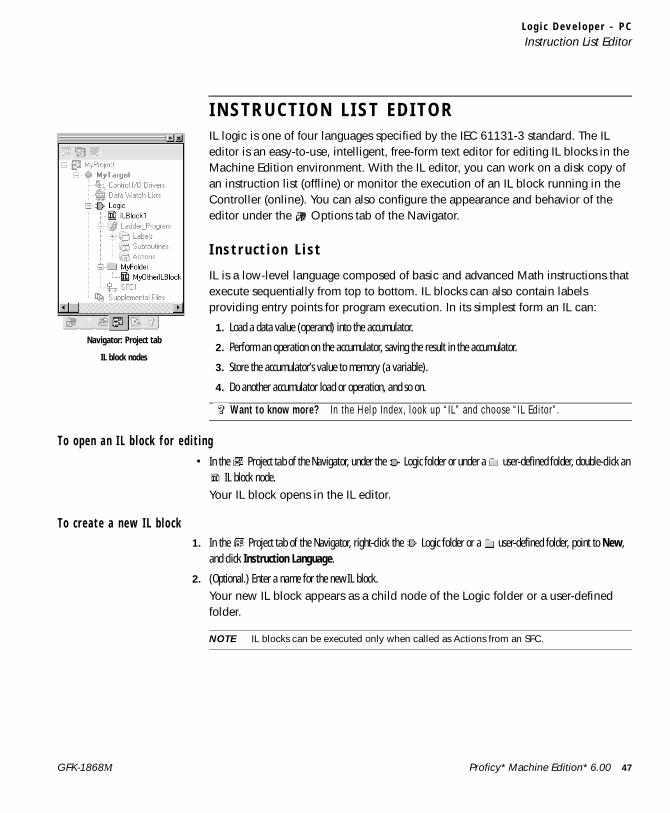
L o g i c D e v e l o p e r - P CInstruction List Editor
I N S T R U C T I O N L I S T E D I T O RIL logic is one of four languages specified by the IEC 61131-3 standard. The IL editor is an easy-to-use, intelligent, free-form text editor for editing IL blocks in the Machine Edition environment. With the IL editor, you can work on a disk copy of an instruction list (offline) or monitor the execution of an IL block running in the Controller (online). You can also configure the appearance and behavior of the editor under the Options tab of the Navigator.
I n s t r u c t i o n L i s t
IL is a low-level language composed of basic and advanced Math instructions that execute sequentially from top to bottom. IL blocks can also contain labels providing entry points for program execution. In its simplest form an IL can:
1. Load a data value (operand) into the accumulator.
2. Perform an operation on the accumulator, saving the result in the accumulator.
3. Store the accumulator’s value to memory (a variable).
4. Do another accumulator load or operation, and so on.
T o ope n a n I L b l o c k f o r e d i t i n g• In the Project tab of the Navigator, under the Logic folder or under a user-defined folder, double-click an
IL block node.Your IL block opens in the IL editor.
T o c r e a t e a n e w I L b l o c k1. In the Project tab of the Navigator, right-click the Logic folder or a user-defined folder, point to New,
and click Instruction Language.
2. (Optional.) Enter a name for the new IL block.Your new IL block appears as a child node of the Logic folder or a user-defined folder.
NOTE IL blocks can be executed only when called as Actions from an SFC.
Want to know more? In the Help Index, look up “IL” and choose “IL Editor”.
Navigator: Project tab
IL block nodes
Proficy* Machine Edition* 6.00 47GFK-1868M
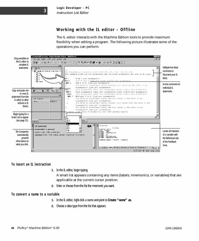
L o g i c D e v e l o p e r - P C
Instruction List Editor3
W o r k i n g w i t h t h e I L e d i t o r - O f f l i n e
The IL editor interacts with the Machine Edition tools to provide maximum flexibility when editing a program. The following picture illustrates some of the operations you can perform.
T o i n s e r t a n I L i n s t r u c t i o n1. In the IL editor, begin typing.
A smart list appears containing any items (labels, mnemonics, or variables) that are applicable at the current cursor position.
2. Enter or choose from the list the mnemonic you want.
T o c on ve r t a n a m e t o a va r i a b l e1. In the IL editor, right-click a name and point to Create “name” as.
2. Choose a data type from the list that appears.
The Companionautomatically
providesinformation onwhat you click.
Copy and paste oneor more IL
statements from theIL editor to other
sections or ILblocks.
Multiple-line block comments to document your IL block.
Drag variables tothe IL editor to
complete ILstatements.
In-line comments for individual IL statements.
Begin typing for aSmart List to appear
(see page 22).
Locate all instances of a variable with the References tab of the Feedback Zone.
48 Proficy* Machine Edition* 6.00 GFK-1868M
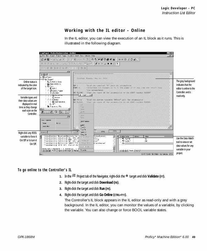
L o g i c D e v e l o p e r - P CInstruction List Editor
W o r k i n g w i t h t h e I L e d i t o r - O n l i n e
In the IL editor, you can view the execution of an IL block as it runs. This is illustrated in the following diagram.
T o go on l i n e t o t he Co n t r o l l e r ’ s I L1. In the Project tab of the Navigator, right-click the target and click Validate (F7).
2. Right-click the target and click Download (F8).
3. Right-click the target and click Run (F9).
4. Right-click the target and click Go Online (CTRL+F11).The Controller’s IL block appears in the IL editor as read-only and with a grey background. In the IL editor, you can monitor the values of a variable, by clicking the variable. You can also change or force BOOL variable states.
Variable types andtheir data values are
displayed in realtime as they change
each scan on theController.
The grey background indicates that the editor is online to the Controller and is read-only.
Online status isindicated by the color
of the target icon.
Use the Data Watch tool to view or set data values for any variable in your project.
Right-click any BOOLvariable to force it
On/Off or to turn itOn/Off.
Proficy* Machine Edition* 6.00 49GFK-1868M
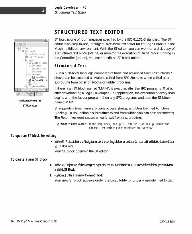
L o g i c D e v e l o p e r - P C
Structured Text Editor3
S T R U C T U R E D T E X T E D I T O RST logic is one of four languages specified by the IEC 61131-3 standard. The ST editor is an easy-to-use, intelligent, free-form text editor for editing ST blocks in the Machine Edition environment. With the ST editor, you can work on a disk copy of a structured text block (offline) or monitor the execution of an ST block running in the Controller (online). You cannot edit an ST block online.
S t r u c t u r e d T e x t
ST is a high-level language composed of basic and advanced Math instructions. ST blocks can be executed as Actions called from SFC Steps, or when called as a subroutine from other ST blocks or ladder programs.
If there is an ST block named ‘MAIN’, it executes after the SFC programs. That is, after downloading a Logic Developer - PC application, the execution of every scan begins with the ladder program, then any SFC programs, and then the ST block named MAIN.
ST supports a timer, arrays, bitwise access, strings, and User Defined Function Blocks (UDFBs—callable subroutines to and from which you can pass parameters). The Return keyword causes an early exit from a subroutine.
T o ope n a n S T b l o c k f o r e d i t i n g• In the Project tab of the Navigator, under the Logic folder or under a user-defined folder, double-click an
ST block node.Your ST block opens in the ST editor.
T o c r e a t e a n e w ST b l o c k1. In the Project tab of the Navigator, right-click the Logic folder or a user-defined folder, point to New,
and click ST Block.
2. (Optional.) Enter a name for the new ST block.Your new ST block appears under the Logic folder or under a user-defined folder.
Want to know more? In the Help Index, look up “ST Editor (PC)” or look up “UDFB” and choose “User Defined Function Blocks: an Overview”.
Navigator: Project tab
ST block nodes
50 Proficy* Machine Edition* 6.00 GFK-1868M
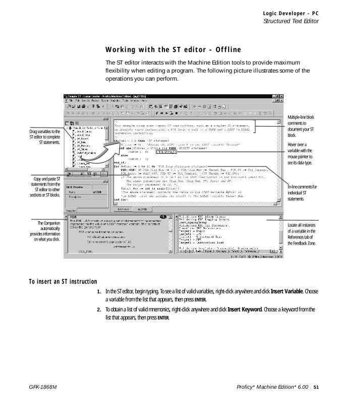
L o g i c D e v e l o p e r - P CStructured Text Editor
W o r k i n g w i t h t h e S T e d i t o r - O f f l i n e
The ST editor interacts with the Machine Edition tools to provide maximum flexibility when editing a program. The following picture illustrates some of the operations you can perform.
To i n s e r t a n ST i n s t r u c t i o n1. In the ST editor, begin typing. To see a list of valid variables, right-click anywhere and click Insert Variable. Choose
a variable from the list that appears, then press ENTER.
2. To obtain a list of valid mnemonics, right-click anywhere and click Insert Keyword. Choose a keyword from the list that appears, then press ENTER.
The Companionautomatically
provides informationon what you click.
Copy and paste STstatements from the
ST editor to othersections or ST blocks.
Multiple-line block comments to document your ST block.
Drag variables to theST editor to complete
ST statements. Hover over a variable with the mouse pointer to see its data type.
Locate all instances of a variable in the References tab of the Feedback Zone.
In-line comments for individual ST statements.
Proficy* Machine Edition* 6.00 51GFK-1868M
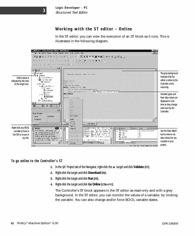
L o g i c D e v e l o p e r - P C
Structured Text Editor3
W o r k i n g w i t h t h e S T e d i t o r - O n l i n e
In the ST editor, you can view the execution of an ST block as it runs. This is illustrated in the following diagram.
T o go on l i n e t o t he Co n t r o l l e r ’ s S T1. In the Project tab of the Navigator, right-click the target and click Validate (F7).
2. Right-click the target and click Download (F8).
3. Right-click the target and click Run (F9).
4. Right-click the target and click Go Online (CTRL+F11).
The Controller’s ST block appears in the ST editor as read-only and with a grey background. In the ST editor, you can monitor the values of a variable, by clicking the variable. You can also change and/or force BOOL variable states.
The grey background indicates that the editor is online to the Controller and is read-only.
Online status isindicated by the color
of the target icon.
Use the Data Watch tool to view or set data values for any variable in your project.
Variable types and their data values are displayed in real time as they change each scan by the Controller.
Right-click any BOOLvariable to force it
On/Off or to turn itOn/Off.
52 Proficy* Machine Edition* 6.00 GFK-1868M
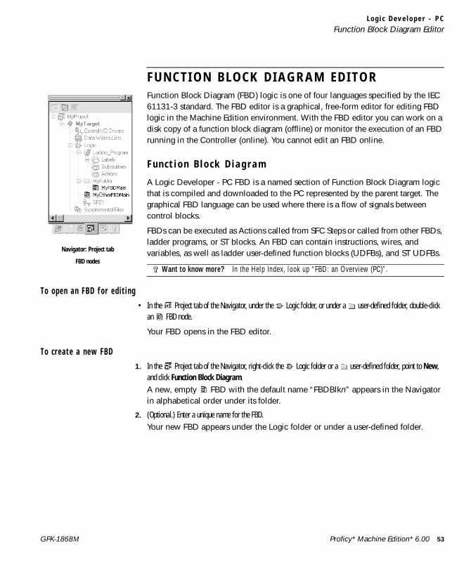
L o g i c D e v e l o p e r - P CFunction Block Diagram Editor
F U N C T I O N B L O C K D I A G R A M E D I T O RFunction Block Diagram (FBD) logic is one of four languages specified by the IEC 61131-3 standard. The FBD editor is a graphical, free-form editor for editing FBD logic in the Machine Edition environment. With the FBD editor you can work on a disk copy of a function block diagram (offline) or monitor the execution of an FBD running in the Controller (online). You cannot edit an FBD online.
F u n c t i o n B l o c k D i a g r a m
A Logic Developer - PC FBD is a named section of Function Block Diagram logic that is compiled and downloaded to the PC represented by the parent target. The graphical FBD language can be used where there is a flow of signals between control blocks.
FBDs can be executed as Actions called from SFC Steps or called from other FBDs, ladder programs, or ST blocks. An FBD can contain instructions, wires, and variables, as well as ladder user-defined function blocks (UDFBs), and ST UDFBs.
T o ope n a n F B D f o r e d i t i n g• In the Project tab of the Navigator, under the Logic folder, or under a user-defined folder, double-click
an FBD node.
Your FBD opens in the FBD editor.
T o c r e a t e a n e w FBD1. In the Project tab of the Navigator, right-click the Logic folder or a user-defined folder, point to New,
and click Function Block Diagram. A new, empty FBD with the default name “FBDBlkn” appears in the Navigator in alphabetical order under its folder.
2. (Optional.) Enter a unique name for the FBD.Your new FBD appears under the Logic folder or under a user-defined folder.
Want to know more? In the Help Index, look up “FBD: an Overview (PC)”.
Navigator: Project tab
FBD nodes
Proficy* Machine Edition* 6.00 53GFK-1868M
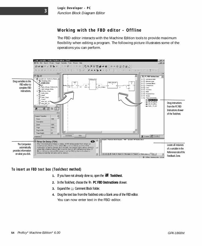
L o g i c D e v e l o p e r - P C
Function Block Diagram Editor3
W o r k i n g w i t h t h e F B D e d i t o r - O f f l i n e
The FBD editor interacts with the Machine Edition tools to provide maximum flexibility when editing a program. The following picture illustrates some of the operations you can perform.
T o i n s e r t a n FBD t e x t b ox ( T oo l c he s t m e t hod )1. If you have not already done so, open the Toolchest.
2. In the Toolchest, choose the PC FBD Instructions drawer.
3. Expand the Comment Block folder.
4. Drag the text box from the Toolchest onto a blank area of the FBD editor. You can now enter text in the FBD editor.
Drag variables to theFBD editor tocomplete FBD
instructions.
The Companionautomatically
provides informationon what you click.
Locate all instances of a variable in the References tab of theFeedback Zone.
Drag instructions from the PC FBD Instructions drawer of the Toolchest.
54 Proficy* Machine Edition* 6.00 GFK-1868M

L o g i c D e v e l o p e r - P CFunction Block Diagram Editor
T o i n s e r t a n FBD te x t b ox ( FB D e d i t o r m e th od )1. In the FBD editor, right-click a blank area and click Insert Instruction.
2. In the smart list that appears, do one of the following:Enter the word “text” (without quotes), and then press ENTER.- or -Scroll down the list, choose Text, and then press ENTER.
3. You can now enter text in the FBD text box.
T o i n s e r t a n FBD i n s t r u c t i o n ( T oo l c h e s t me t h od )1. If you have not already done so, open the Toolchest.
2. In the Toolchest, choose the PC FBD Instructions drawer
3. Expand an FBD instruction group.
4. Drag an FBD instruction from the Toolchest onto a blank area of the FBD editor.
5. Assign parameters above (for Call, Counter, and Timer instructions) and beside the FBD instruction, or draw wires to or from the FBD instruction.
To i n s e r t a n FBD i n s t r u c t i o n ( F BD ed i t o r me t h od )1. In the FBD editor, right-click a blank area and click Insert Instruction.
2. In the smart list that appears, enter or choose an FBD instruction.
3. Assign parameters above (for Call, Counter, and Timer instructions) and beside the FBD instruction, or draw wires to or from the FBD instruction.
Proficy* Machine Edition* 6.00 55GFK-1868M
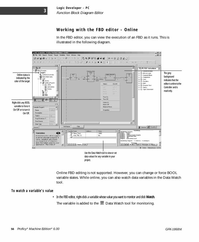
L o g i c D e v e l o p e r - P C
Function Block Diagram Editor3
W o r k i n g w i t h t h e F B D e d i t o r - O n l i n e
In the FBD editor, you can view the execution of an FBD as it runs. This is illustrated in the following diagram.
Online FBD editing is not supported. However, you can change or force BOOL variable states. While online, you can also watch data variables in the Data Watch tool.
T o wa t c h a v a r i a b l e ’ s va l u e• In the FBD editor, right-click a variable whose value you want to monitor and click Watch.
The variable is added to the Data Watch tool for monitoring.
Online status isindicated by the
color of the target
Right-click any BOOLvariable to force it
On/Off or to turn itOn/Off.
The grey background indicates that the editor is online to the Controller and is read-only.
Use the Data Watch tool to view or set data values for any variable in your project.
56 Proficy* Machine Edition* 6.00 GFK-1868M
L o g i c D e v e l o p e r - P CLogic Developer - PC Web Access
L O G I C D E V E L O P E R - P C W E B A C C E S SMachine Edition enables you to view a target’s PC logic data with a web browser, such as Microsoft Internet Explorer (version 4.0 or later is required). When a Machine Edition project is downloaded, it automatically launches an integrated web server. Users who connect to the target computer over the web are presented with the Site Index, from which they can select the Logic Navigator. (If the target has an HMI, Web Access options for the HMI appear as well.)
The Logic Navigator presents a tree diagram of PC logic stored in the Controller, where you can browse to specific programs and blocks:■ Published SFCs and SFC macros. ■ Ladder program. ■ Ladder subroutines.■ Actions.■ ST blocks.■ IL blocks
Click any logic block in the tree to view it.
T o a l l o w r e m o t e a c c e s s t o yo u r p r o j e c t1. For each target that you want to allow access to, set the target’s Publish Logic property to True.
This enables all PC logic except SFCs and SFC macros to be remotely viewable.
2. For each SFC and SFC macro in those targets that you want users to access, set its Publish property to True.For example, to allow users to view an SFC remotely, set the SFC’s Publish property to True.
NOTE The target containing the PC logic to be published must be set as the active target and a successful project download must occur.
T o a c c e s s t h e P C l o g i c S i t e I nde x1. Start Internet Explorer. You can also install Internet Explorer from the Machine Edition installation CD.
2. In the Address box in Internet Explorer, enter the computer name or IP address of the run-time computer.
3. If you’re not sure what the run-time computer’s name or IP address is, check the properties of the TCP/IP driver in the Control Panel Network setup, or contact your network administrator.
4. If you’re testing the project on the local computer, enter “localhost” (without the quotation marks) as the Address. This connects Internet Explorer with the local computer.
Want to know more? In the InfoView tab of the Navigator, expand the Web Access library, and then select a topic under the “PC Web Access features” book.
Proficy* Machine Edition* 6.00 57GFK-1868M
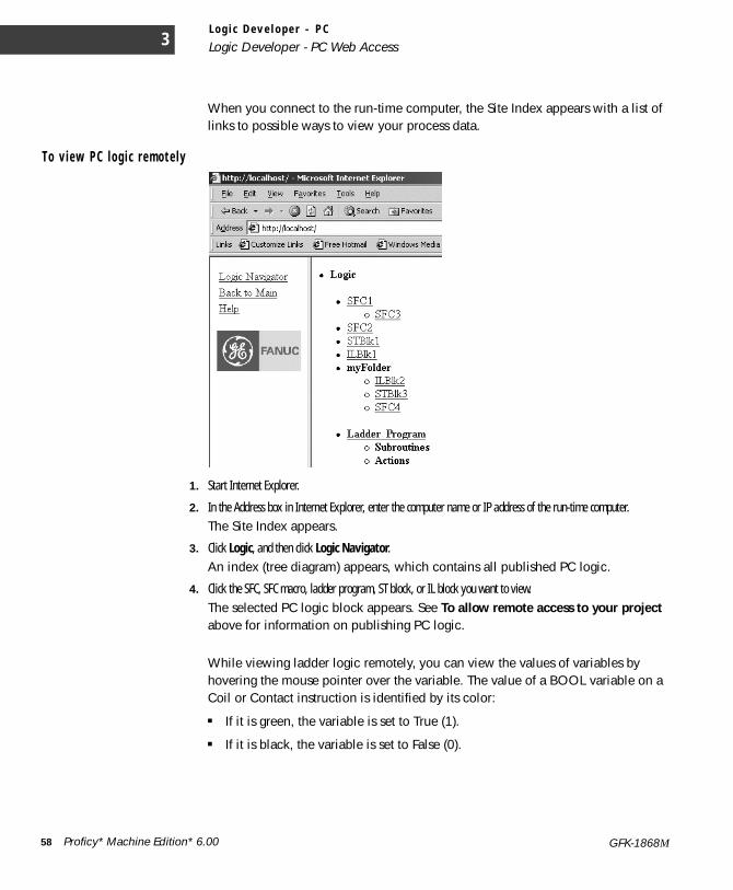
L o g i c D e v e l o p e r - P C
Logic Developer - PC Web Access3
When you connect to the run-time computer, the Site Index appears with a list of links to possible ways to view your process data.
T o v i e w P C l o g i c r e m o t e l y
1. Start Internet Explorer.
2. In the Address box in Internet Explorer, enter the computer name or IP address of the run-time computer.The Site Index appears.
3. Click Logic, and then click Logic Navigator. An index (tree diagram) appears, which contains all published PC logic.
4. Click the SFC, SFC macro, ladder program, ST block, or IL block you want to view. The selected PC logic block appears. See To allow remote access to your project above for information on publishing PC logic.
While viewing ladder logic remotely, you can view the values of variables by hovering the mouse pointer over the variable. The value of a BOOL variable on a Coil or Contact instruction is identified by its color:
■ If it is green, the variable is set to True (1).
■ If it is black, the variable is set to False (0).
58 Proficy* Machine Edition* 6.00 GFK-1868M
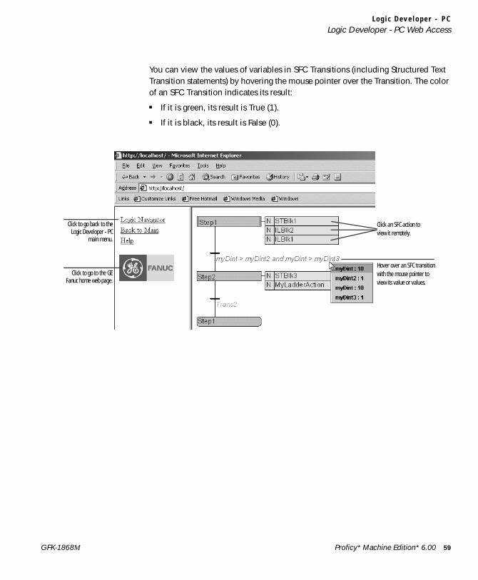
L o g i c D e v e l o p e r - P CLogic Developer - PC Web Access
You can view the values of variables in SFC Transitions (including Structured Text Transition statements) by hovering the mouse pointer over the Transition. The color of an SFC Transition indicates its result:
■ If it is green, its result is True (1).
■ If it is black, its result is False (0).
Click to go back to theLogic Developer - PC
main menu.
Click to go to the GEFanuc home web page.
Click an SFC action to view it remotely.
Hover over an SFC transition with the mouse pointer to view its value or values.
Proficy* Machine Edition* 6.00 59GFK-1868M
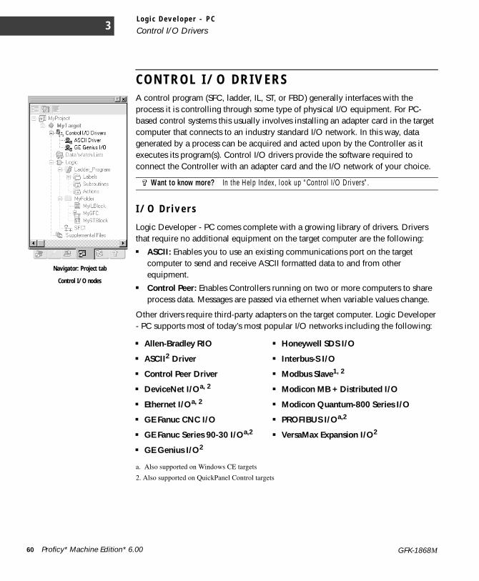
L o g i c D e v e l o p e r - P C
Control I/O Drivers3
C O N T R O L I / O D R I V E R SA control program (SFC, ladder, IL, ST, or FBD) generally interfaces with the process it is controlling through some type of physical I/O equipment. For PC-based control systems this usually involves installing an adapter card in the target computer that connects to an industry standard I/O network. In this way, data generated by a process can be acquired and acted upon by the Controller as it executes its program(s). Control I/O drivers provide the software required to connect the Controller with an adapter card and the I/O network of your choice.
I / O D r i v e r s
Logic Developer - PC comes complete with a growing library of drivers. Drivers that require no additional equipment on the target computer are the following:■ ASCII: Enables you to use an existing communications port on the target
computer to send and receive ASCII formatted data to and from other equipment.
■ Control Peer: Enables Controllers running on two or more computers to share process data. Messages are passed via ethernet when variable values change.
Other drivers require third-party adapters on the target computer. Logic Developer - PC supports most of today’s most popular I/O networks including the following:
Want to know more? In the Help Index, look up “Control I /O Drivers”.
■ Allen-Bradley RIO ■ Honeywell SDS I/O
■ ASCII2 Driver ■ Interbus-S I/O
■ Control Peer Driver ■ Modbus Slave1, 2
■ DeviceNet I/Oa, 2
a. Also supported on Windows CE targets
2. Also supported on QuickPanel Control targets
■ Modicon MB + Distributed I/O
■ Ethernet I/Oa, 2 ■ Modicon Quantum-800 Series I/O
■ GE Fanuc CNC I/O ■ PROFIBUS I/Oa,2
■ GE Fanuc Series 90-30 I/Oa,2 ■ VersaMax Expansion I/O2
■ GE Genius I/O2
Navigator: Project tab
Control I/O nodes
60 Proficy* Machine Edition* 6.00 GFK-1868M

L o g i c D e v e l o p e r - P CControl I/O Drivers
To add a C on t r o l I / O d r i v e r t o a t a r g e t• Right-click the Control I/O Drivers node, point to New Driver, and choose a driver from the list.
The new driver appears as a child node under the Control I/O node. A default configuration of the driver is also added to the Control I/O tool. You can add up to nine drivers to a target.
C o n t r o l I / O T o o l
Cont ro l I/O The Control I/O tool is a special editor used to graphically model the I/O equipment driven by Control I/O drivers. Each I/O system is displayed in a tree structure starting with a driver node branching down to terminals that represent physical field connections. Between the driver and terminals are nodes representing any cards, racks, or modules included in the system. Field data is shared with the components of your project by mapping variables to each I/O terminal.
Want to know more? In the Help Index, look up “Control I /O Tool”.
Proficy* Machine Edition* 6.00 61GFK-1868M
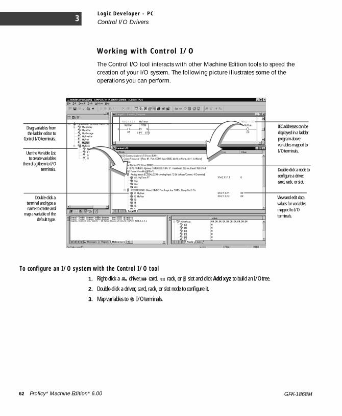
L o g i c D e v e l o p e r - P C
Control I/O Drivers3
W o r k i n g w i t h C o n t r o l I / O
The Control I/O tool interacts with other Machine Edition tools to speed the creation of your I/O system. The following picture illustrates some of the operations you can perform.
T o c on f i g u r e a n I/ O sy s t e m w i t h t h e Con t r o l I/ O t oo l1. Right-click a driver, card, rack, or slot and click Add xyz to build an I/O tree.
2. Double-click a driver, card, rack, or slot node to configure it.
3. Map variables to I/O terminals.
Use the Variable Listto create variables
then drag them to I/Oterminals.
IEC addresses can be displayed in a ladder program above variables mapped to I/O terminals.
Drag variables fromthe ladder editor to
Control I/O terminals.
Double-click a node to configure a driver, card, rack, or slot.
View and edit data values for variables mapped to I/O terminals.
Double-click aterminal and type aname to create and
map a variable of thedefault type.
62 Proficy* Machine Edition* 6.00 GFK-1868M
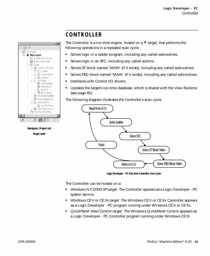
L o g i c D e v e l o p e r - P CController
C O N T R O L L E RThe Controller is a run-time engine, hosted on a target, that performs the following operations in a repeated scan cycle:
■ Solves logic in a ladder program, including any called subroutines.
■ Solves logic in an SFC, including any called actions.
■ Solves ST block named ‘MAIN’ (if it exists), including any called subroutines.
■ Solves FBD block named ‘MAIN’ (if it exists), including any called subroutines.
■ Interfaces with Control I/O drivers.
■ Updates the target’s run-time database, which is shared with the View Runtime (see page 90).
The following diagram illustrates the Controller’s scan cycle.
The Controller can be hosted on a:■ Windows NT/2000/XP target. The Controller appears as a Logic Developer - PC
system service.■ Windows CE II or CE IIx target. The Windows CE II or CE IIx Controller appears
as a Logic Developer - PC program running under Windows CE II or CE IIx.■ QuickPanel View/Control target. The Windows QuickPanel Control appears as
a Logic Developer - PC Controller program running under Windows CE III.
Navigator: Project tab
Target node
Read from I/O
Solve ladder
Solve SFC
Solve ST Block Main
Solve FBD Block Main
Yield
Logic Developer - PC Run-time Controller Scan Cycle
Write to I/O
Proficy* Machine Edition* 6.00 63GFK-1868M
L o g i c D e v e l o p e r - P C
Controller3
You specify a target when creating a project. The Controller automatically starts when the target operating system is started.
W o r k i n g w i t h t h e C o n t r o l l e r
The Controller’s location (IP address or computer name), performance (scan rate or tuning), and behavior (response to faults, watchdog timer, and shutdown procedure) are configured by setting the properties of the target it resides on.
T o c on f i g u r e t he Con t r o l l e r1. In the Project tab of the Navigator, right-click a target and click Properties.
2. In the Inspector, adjust the properties.If your project includes an HMI component, properties of the View Runtime can also be set at this time. You can also configure the Controller’s properties by selecting Properties from the Controller menu. In this case, the Controller Properties dialog box appears. The information in the dialog box is the same as in the Inspector—just represented differently.
The logic component of a project must be downloaded to the Controller before the project can be run.
T o d ow n l o a d a l o g i c c om p on e n t t o t h e C on t r o l l e r• In the Project tab of the Navigator, right-click a target and click Download.
All components on the selected target are validated and, if no errors exist, they are downloaded to the specified computer. Errors listed in the Build tab of the Feedback Zone must be corrected before a download can be completed. Logic components are downloaded to the Controller, while HMI components are downloaded to the View Runtime.
Although the Controller service is always running, you still have control over the execution of your control programs. Offline, you can start, stop, and reset execution. When online to the Controller, additional commands are available to pause, single-scan, or enable forces.
Want to know more? In the Help Index, look up “PC Logic Controller: an Overview”.
64 Proficy* Machine Edition* 6.00 GFK-1868M
L o g i c D e v e l o p e r - P CController
Ru n Mo de S t o r eWith the Run Mode Store (RMS) functionality, you can update a target Controller’s program without stopping the Controller. It is supported on all Logic Developer - PC targets.
When you attempt to download your project to the Controller, the Download to Controller dialog box appears with the following options.■ Attempt a Run Mode Store: Machine Edition attempts a Run Mode Store
operation. That is, it tries to download your logic to the Controller while the Controller is running.
■ Stop the Controller, then download: Machine Edition does not attempt to use the Run Mode Store feature. Instead, it stops the Controller before initiating the download operation.
■ Download Retentive Initial Values: Choose whether to download initial values of retentive variables, which may have changed since the previous download.
Several system tests and checks are performed when attempting a Run Mode Store operation. If these tests fail, the logic program may not be downloaded to the Controller.
T o r un t h e C on t r o l l e r• In the Project tab of the Navigator, right-click a target, point to Online Commands or Offline
Commands, and click Start Runtime.The ladder program, SFC program(s), the ST block named ‘MAIN’, and the FBD block named ‘MAIN’ begin executing on the target computer or unit. If the target also has an HMI component (see page 90), the View Runtime is started at the same time as the Controller.
To validate, download and run a project, right-click a target and click Download and Start “targetname”.
W a r m S t a n d b y
The Warm Standby feature provides an extra level of reliability for critical Windows NT/2000/XP, Windows CE II and CE IIx, and QuickPanel Control applications. It consists of two Controllers running the Logic Developer - PC Controller (a primary and secondary or warm standby Controller), and an I/O switch that determines which Controller is currently connected to the physical I/O.
When a system using warm standby is started, the primary Controller is connected to the I/O, solves logic, and updates the secondary Controller with critical data.
Want to know more? In the Help Index, look up “Run Mode Store (RMS) (PC)”.
Proficy* Machine Edition* 6.00 65GFK-1868M

L o g i c D e v e l o p e r - P C
Controller3
The secondary Controller receives the data and monitors the status of the primary Controller. When a fault is detected in the primary Controller, or when the secondary Controller cannot communicate with the primary Controller, the I/O connection is automatically switched to the secondary Controller and the secondary Controller takes over operations.
W o r k i n g w i t h W a r m S t a n d b y
You must set up the warm standby hardware before you can configure the warm standby system.
To c o n f i g u r e Wa rm S t an dby1. In the Project tab of the Navigator, right-click a Windows NT/2000/XP, Windows CE II/IIx, or QuickPanel
Control target and click Properties.
2. In the Inspector, scroll to the +Redundant System group of properties and double-click it to expand the group.
3. Click the Redundant Mode property and click Warm Standby.
4. Click the Controller Mode property and choose a value from the list.
Want to know more? In the Help Index, look up “warm” and choose “Warm Standby”.
66 Proficy* Machine Edition* 6.00 GFK-1868M

L o g i c D e v e l o p e r - P CController
H o t S t a n d b y
The Hot Standby feature provides a high level of reliability for critical Windows NT/2000/XP applications. It consists of two Controllers running the Logic Developer - PC Controller (a primary and secondary or hot standby Controller) over a GE Genius I/O network. The GE Genius driver automatically handles the switching between the Controllers.
To download to a target with hot standby, the primary and secondary Controllers must be synchronized, that is, they must both be downloaded.
By default, the primary Controller is active and the secondary Controller is the backup. The backup Controller sets itself to active when one of the following takes place:■ A fault of a specified type occurs. (See To configure a Hot Standy, below.)■ A loss of communication occurs with the active Controller via the VMIPCI-
5565 reflective memory cards.■ The target's Secondary Switch Time has elapsed.
Both Controllers can read from the network; however, only the active Controller can write to the network.
W o r k i n g w i t h H o t S t a n d b y
You must set up the hot standby hardware before you can configure the hot standby system.
To c o n f i g u r e Ho t S t a n dby1. In the Project tab of the Navigator, right-click a Windows NT/2000/XP target and click Properties.
2. In the Inspector, scroll to the +Redundant System group of properties and double-click it to expand the group.
3. Click the Redundant Mode property and click Hot Standby.
4. Click the Secondary Address property and enter the IP address (Controller name) of the secondary Controller.
5. Click the Secondary Switch Fault property and choose the type of fault the secondary Controller will become active on.
6. Click the Secondary Node ID property and assign a unique node ID to the VMIPCI-5565 card of the secondary Controller.
7. Click the Secondary Switch Time (ms) property and enter the number of milliseconds the secondary Controller is to wait for communication from the primary Controller before setting itself up as the active Controller.
Want to know more? In the Help Index, look up “hot” and choose “Hot Standby”.
Proficy* Machine Edition* 6.00 67GFK-1868M
L o g i c D e v e l o p e r - P C
Controller3
8. Click the Primary Node ID property and assign a unique node ID to the VMIPCI-5565 card of the primary Controller.
9. Click the Primary Wait Time (ms) property and enter the number of milliseconds the primary Controller is to wait for communication from the secondary Controller before setting its synchronization bit to False.
O P C S e r v e r s , W a r m S t a n d b y , a n d H o t S t a n d b y
Warm standby and hot standby are fully supported by the Logic Developer - PC OPC server for Machine Edition. When a configuration file is detected, the OPC server does the following:■ It generates internal objects so that it recognizes all warm standby or hot
standby configurations as logical Controllers to OPC clients.■ It creates predefined OPC items for each logical Controller. These items
indicate which physical Controller is active and the statuses of the primary and secondary Controllers.
To c o n f i g u r e a n OP C s e r v e r f o r Ho t S ta ndby an d Warm S t an dby• Edit the “OPCWarmStandby.HTML” file, located in the same folder as LogicPC_OPC.EXE on the computer hosting the
OPC Server.This XML file is used for both the Warm Standby and Hot Standby features. By default, this file is located in the “C:\Program Files\GE Fanuc\Proficy Machine Edition\OPC” directory.
68 Proficy* Machine Edition* 6.00 GFK-1868M
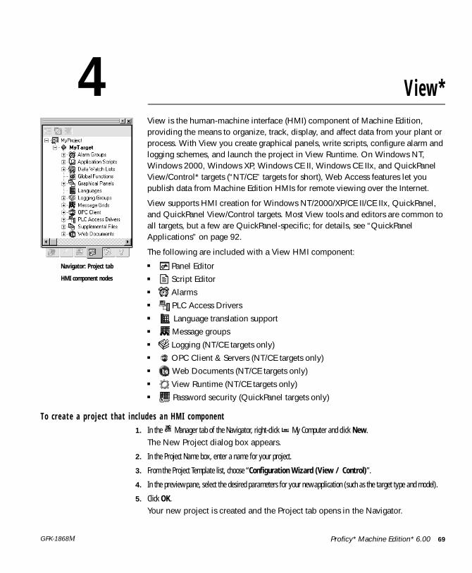
4 View*View is the human-machine interface (HMI) component of Machine Edition, providing the means to organize, track, display, and affect data from your plant or process. With View you create graphical panels, write scripts, configure alarm and logging schemes, and launch the project in View Runtime. On Windows NT, Windows 2000, Windows XP, Windows CE II, Windows CE IIx, and QuickPanel View/Control* targets (“NT/CE” targets for short), Web Access features let you publish data from Machine Edition HMIs for remote viewing over the Internet.
View supports HMI creation for Windows NT/2000/XP/CE II/CE IIx, QuickPanel, and QuickPanel View/Control targets. Most View tools and editors are common to all targets, but a few are QuickPanel-specific; for details, see “QuickPanel Applications” on page 92.
The following are included with a View HMI component:■ Panel Editor■ Script Editor■ Alarms■ PLC Access Drivers■ Language translation support■ Message groups■ Logging (NT/CE targets only)■ OPC Client & Servers (NT/CE targets only)■ Web Documents (NT/CE targets only)■ View Runtime (NT/CE targets only)■ Password security (QuickPanel targets only)
T o c r e a t e a p r o j e c t t ha t i n c l u d e s a n HMI c om p on e n t1. In the Manager tab of the Navigator, right-click My Computer and click New.
The New Project dialog box appears.
2. In the Project Name box, enter a name for your project.
3. From the Project Template list, choose “Configuration Wizard (View / Control)”.
4. In the preview pane, select the desired parameters for your new application (such as the target type and model).
5. Click OK. Your new project is created and the Project tab opens in the Navigator.
Navigator: Project tab
HMI component nodes
Proficy* Machine Edition* 6.00 69GFK-1868M
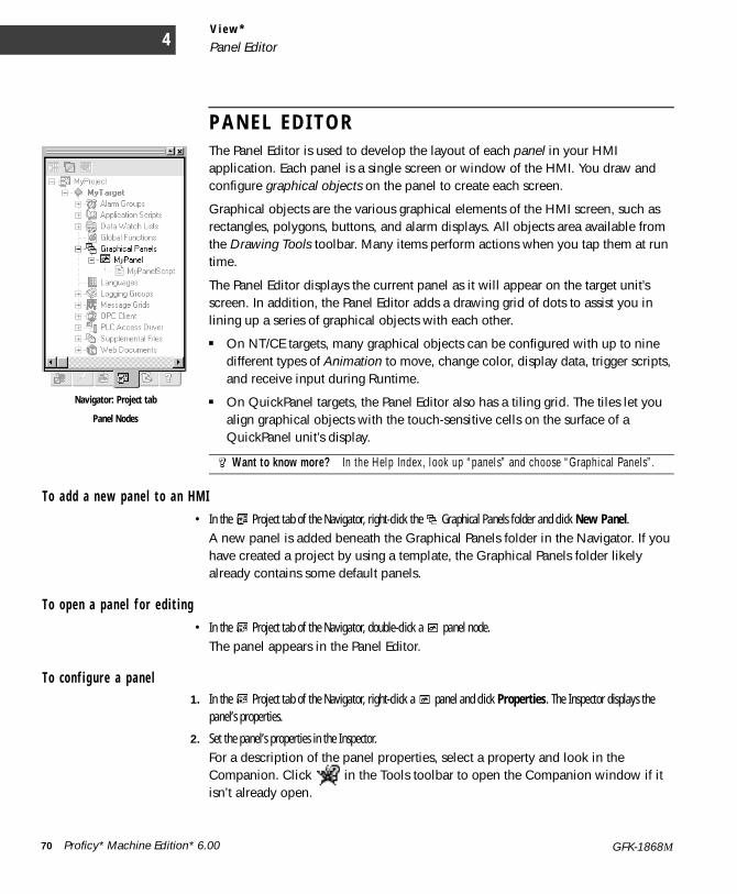
V i e w *
Panel Editor4
P A N E L E D I T O RThe Panel Editor is used to develop the layout of each panel in your HMI application. Each panel is a single screen or window of the HMI. You draw and configure graphical objects on the panel to create each screen.
Graphical objects are the various graphical elements of the HMI screen, such as rectangles, polygons, buttons, and alarm displays. All objects area available from the Drawing Tools toolbar. Many items perform actions when you tap them at run time.
The Panel Editor displays the current panel as it will appear on the target unit’s screen. In addition, the Panel Editor adds a drawing grid of dots to assist you in lining up a series of graphical objects with each other.
■ On NT/CE targets, many graphical objects can be configured with up to nine different types of Animation to move, change color, display data, trigger scripts, and receive input during Runtime.
■ On QuickPanel targets, the Panel Editor also has a tiling grid. The tiles let you align graphical objects with the touch-sensitive cells on the surface of a QuickPanel unit’s display.
To add a n e w pan e l t o a n HMI• In the Project tab of the Navigator, right-click the Graphical Panels folder and click New Panel.
A new panel is added beneath the Graphical Panels folder in the Navigator. If you have created a project by using a template, the Graphical Panels folder likely already contains some default panels.
T o ope n a p a n e l f o r e d i t i n g• In the Project tab of the Navigator, double-click a panel node.
The panel appears in the Panel Editor.
T o c on f i g u r e a p a ne l1. In the Project tab of the Navigator, right-click a panel and click Properties. The Inspector displays the
panel’s properties.
2. Set the panel’s properties in the Inspector. For a description of the panel properties, select a property and look in the Companion. Click in the Tools toolbar to open the Companion window if it isn’t already open.
Want to know more? In the Help Index, look up “panels” and choose “Graphical Panels”.
Navigator: Project tab
Panel Nodes
70 Proficy* Machine Edition* 6.00 GFK-1868M
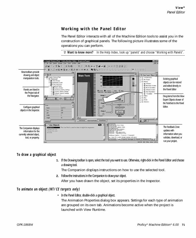
V i e w *Panel Editor
W o r k i n g w i t h t h e P a n e l E d i t o r
The Panel Editor interacts with all of the Machine Edition tools to assist you in the construction of graphical panels. The following picture illustrates some of the operations you can perform.
To d r aw a g r aph i c a l o b j e c t1. If the Drawing toolbar is open, select the tool you want to use. Otherwise, right-click in the Panel Editor and choose
a drawing tool. The Companion displays instructions on how to use the selected tool.
2. Follow the instructions in the Companion to draw your object.After you have drawn the object, set its properties in the Inspector.
T o a n i m a t e a n o b j e c t ( NT / CE t a r g e t s o n l y )• In the Panel Editor, double-click a graphical object.
The Animation Properties dialog box appears. Settings for each type of animation are grouped on its own tab. Animations become active when the project is launched with View Runtime.
Want to know more? In the Help Index, look up “panels” and choose “Working with Panels”.
Existing graphical objects can be resized and edited directly in the Panel Editor
Drag items from the View Expert Objects drawer of the Toolchest to the Panel Editor.
The Feedback Zone updates with information when you validate, download, or run your project.
View toolbars providedrawing and objectmanipulation tools.
Panels are listed inthe Project tab of
the Navigator.
Configure graphicalobjects in the Inspector.
The Companion displaysinformation for the
currently selected object,tool, or property.
Proficy* Machine Edition* 6.00 71GFK-1868M
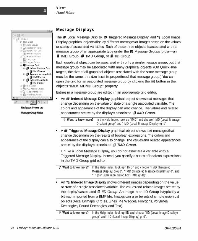
V i e w *
Panel Editor4
M e s s a g e D i s p l a y s
The Local Message Display, Triggered Message Display, and Local Image Display graphical objects display different messages or images based on the values or states of associated variables. Each of these three objects is associated with a message group of an appropriate type under the Message Groups folder—an
IMD Group, TMD Group, or IID Group.
Each graphical object can be associated with only a single message group, but that message group may be associated with many graphical objects. (On QuickPanel targets, the size of all graphical objects associated with the same message group must be the same; this size is set in properties of that message group.) You can open the grid for an associated message group by clicking the button in the object’s “IMD/TMD/IID Group” property.
Entries in a message group are edited in an appropriate grid editor.
■ An Indexed Message Display graphical object shows text messages that change depending on the value or state of a single associated variable. The colors and appearance of the display can also change. The values and related appearances are set by the display’s associated IMD Group.
■ A Triggered Message Display graphical object shows text messages that change depending on the results of boolean expressions. The colors and appearance of the display can also change. The values and related appearances are set by the display’s associated TMD Group.
Unlike a Local Message Display, you do not associate a variable with a Triggered Message Display. Instead, you specify a series of boolean expressions in the TMD Group grid editor.
■ An Indexed Image Display shows different images depending on the value or state of a single associated variable. The values and related images are set by the display’s associated IID Group. An image in an IID Group is typically a bitmap, imported from a BMP file. Images can also be sets of simple graphical objects (Arcs, Bitmaps, Circles, Lines, Pie Wedges, Polygons, Polylines, Rectangles, Round Rectangles, and Text).
Want to know more? In the Help Index, look up “IMD” and choose “IMD (Local Message Display) group” and “IMD (Local Message Display) grid”.
Want to know more? In the Help Index, look up “TMD” and choose “TMD (Triggered Message Display) group”, “TMD (Triggered Message Display) grid”, and “Trigger Expression dialog box (TMD grids)”.
Want to know more? In the Help Index, look up IID and choose “IID (Local Image Display) group” and “IID (Local Image Display) grid”.
Navigator: Project tab
Message Group Nodes
72 Proficy* Machine Edition* 6.00 GFK-1868M
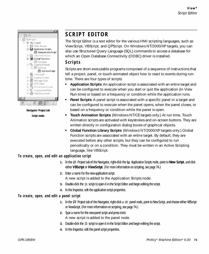
V i e w *Script Editor
S C R I P T E D I T O RThe Script Editor is a text editor for the various HMI scripting languages, such as ViewScript, VBScript, and QPScript. On Windows NT/2000/XP targets, you can also use Structured Query Language (SQL) commands to access a database for which an Open Database Connectivity (ODBC) driver is installed.
S c r i p t sScripts are short executable programs composed of a sequence of instructions that tell a project, panel, or touch-animated object how to react to events during run-time. There are four types of scripts:■ Application Scripts: An application script is associated with an entire target and
can be configured to execute when you start or quit the application (in View Run-time) or based on a frequency or condition while the application runs.
■ Panel Scripts: A panel script is associated with a specific panel in a target and can be configured to execute when the panel opens, when the panel closes, or based on a frequency or condition while the panel is open.
■ Touch Animation Scripts: (Windows NT/CE targets only.) At run time, Touch Animation scripts are activated with keystrokes and on-screen buttons. They are written directly in configuration dialog boxes of graphical objects.
■ Global Function Library Scripts: (Windows NT/2000/XP targets only.) Global Function scripts are associated with an entire target. By default, they are executed before any other scripts, but they can be configured to run periodically or on a condition. They must be written in an Active Scripting language, like VBScript.
To c r e a t e , o p en , a n d ed i t a n a pp l i c a t i o n s c r i p t1. In the Project tab of the Navigator, right-click the Application Scripts node, point to New Script, and click
either VBScript or ViewScript. (For more information on scripting, see page 74.)
2. Enter a name for the new application script.A new script is added to the Application Scripts node.
3. Double-click the script to open it in the Script Editor and begin editing the script.
4. In the Inspector, edit the application script properties.
To c r e a t e , o p en , a n d ed i t a p an e l s c r i p t1. In the Project tab of the Navigator, right-click a panel node, point to New Script, and choose either VBScript
or ViewScript. (For more information on scripting, see page 74.)
2. Type a name for the new panel script and press ENTER.A new script is added to the panel node.
3. Double-click the script to open it in the Script Editor and begin editing the script.
4. In the Inspector, edit the panel script properties.
Navigator: Project tab
Script nodes
Proficy* Machine Edition* 6.00 73GFK-1868M
V i e w *
Script Editor4
T o c r e a t e a t o u c h a n i m a t i o n s c r i p t1. In the Panel Editor, double-click the object you want to animate. The Configure Animation dialog box appears.
2. Click the Touch tab.
3. Select the Enable Touch Action Animation check box and choose a touch action command that will execute a script.
4. In the large edit box, type the script that will run when the object is touched.
To c r e a t e a g l o ba l f u n c t i o n l i b r a r y s c r i p t1. In the Project tab of the Navigator, right-click Global Functions, point to New Library, and click VBScript.
A new script is added to the Global Functions node.
2. Double-click the script to open it in the Script Editor and begin editing the script.
3. In the Inspector, edit the Global Function Library script properties, in other words, the name.
S c r i p t i n g L a n g u a g e s
On Windows NT /2000/XP and some Windows CE targets, Machine Edition supports two types of scripting languages: the proprietary ViewScript language and VBScript Active Scripting languages (using Microsoft’s Active Scripting engine). On other targets, Machine Edition supports only proprietary ViewScript language.
On QuickPanel targets, Machine Edition uses the proprietary QPScript language (see page 93).
ViewScript scripting language
The ViewScript scripting language consists of the following:■ Keywords: View script keywords are a basic set of commands that are used to
control the flow of a script and to create local variables.■ Operators: View operators are used to assign variable values and to perform
mathematical operations■ Script Functions: View script functions are commands that can be written into
the body of your script to monitor and react to changes in variable values. Functions are grouped in the following categories: ActiveX, Alarm Management, Animation, Application Access, CSV, File Management, Initialization File Management, List and Combo Box, Logging, Miscellaneous, Network, Panel Management, Screen Navigation, Security, Serial Communication, Statistical Process Control, SQL, String, System, Trend Management, Video/Sound, and Web.
74 Proficy* Machine Edition* 6.00 GFK-1868M
V i e w *Script Editor
■ Comments: Placing comments in, or between, the lines of your script is useful for debugging your script and for future reference.
Active Scripting
Active Scripting lets Machine Edition use external scripting languages through a COM interface. Active Scripting languages are supported only on Windows NT/2000/XP and some Windows CE targets. Currently, only the VBScript Active Scripting language is supported.
By default, new projects use VBScript. You can override this default by setting a user preference.
A target can contain scripts written in either ViewScript or VBScript. Troubleshooting such a project can be quite difficult, however, so this practice is not recommended.
Va l i d a t i ng a s c r i p t wr i t t e n i n a n A c t i v e S c r i p t i n g l a n gu ageActive scripting languages are validated at run-time. You can also validate a project at any time during development to check:■ Syntax for View function calls.■ Syntax for variable, array, and structure element references.■ Limited checks for VBScript syntax.
V B S c r i p t S y n t a x
A detailed explanation of VBScript syntax is beyond the scope of this manual. For more information on the VBScript language usage, syntax and examples, look up VBScript at Microsoft’s website (www.microsoft.com).
A c t i v e S c r i p t i n g O b j e c t s
Active Scripting provides a mechanism to extend a scripting language through custom COM objects. Variable syntax is, therefore, limited to using properties and methods on a COM object.
Want to know more? In the Help Index, look up “Viewscript” and choose “ViewScript HMI scripting language”.
Want to know more? In the Help Index, look up “scripts” and choose “View Scripts: an Overview”, or look up “scripting” and choose “Active Scripting in View: an Overview”.
Want to know more? In the Help Index, look up “VBScript” and choose “VBScript language: an Overview”.
Proficy* Machine Edition* 6.00 75GFK-1868M
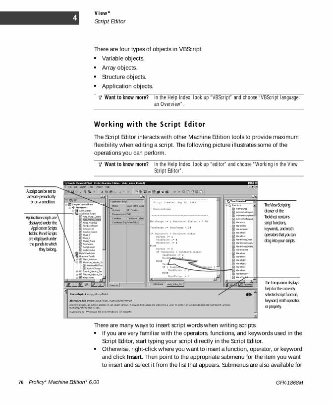
V i e w *
Script Editor4
There are four types of objects in VBScript: ■ Variable objects.■ Array objects.■ Structure objects.■ Application objects.
W o r k i n g w i t h t h e S c r i p t E d i t o r
The Script Editor interacts with other Machine Edition tools to provide maximum flexibility when editing a script. The following picture illustrates some of the operations you can perform.
There are many ways to insert script words when writing scripts.■ If you are very familiar with the operators, functions, and keywords used in the
Script Editor, start typing your script directly in the Script Editor.■ Otherwise, right-click where you want to insert a function, operator, or keyword
and click Insert. Then point to the appropriate submenu for the item you want to insert and select it from the list that appears. Submenus are also available for
Want to know more? In the Help Index, look up “VBScript” and choose “VBScript language: an Overview”.
Want to know more? In the Help Index, look up “editor” and choose “Working in the View Script Editor”.
The View Scripting drawer of the Toolchest contains script functions, keywords, and math operators that you can drag into your scripts.
Application scripts aredisplayed under the
Application Scriptsfolder. Panel Scriptsare displayed underthe panels to which
they belong.
The Companion displays help for the currently selected script function, keyword, math operator, or property.
A script can be set toactivate periodically
or on a condition.
76 Proficy* Machine Edition* 6.00 GFK-1868M
V i e w *Grid Editors
names of the project’s variables, panels, scripts, alarm groups and logging groups. For a description of a script function, keyword, or math operator, while in the Script Editor, move the cursor on the word and press F1.
■ All the math operators, script functions, and script keywords are also listed in the Toolchest and can be dragged into your script. The Companion provides a description of each item.
G R I D E D I T O R SWith various grid editors, you can create and edit several items in your HMI targets within a spreadsheet-like table. Among the features that use grid editors are:■ Word Alarm groups■ Bit Alarm groups■ IMD (Local Message Display) groups■ TMD (Triggered Message Display) groups■ Selector Switches■ Bar Graphs■ Language translations■ Trend displays ■ Passwords list (QuickPanel targets only) ■ External Keypad assignment configuration
The exact functionality depends on the specific editor, but in general you can:■ Double-click a cell to edit its contents.■ Right-click a cell to perform various operations on the cell.■ Select an entire row (by clicking the grey button row headers on the left), then
right-clicking the selection to perform operations on the row
Want to know more? In the Help Index, look up “Working with QuickPanel grid editors”. You can also press F1 while working in the grid for a description of that editor.
Proficy* Machine Edition* 6.00 77GFK-1868M
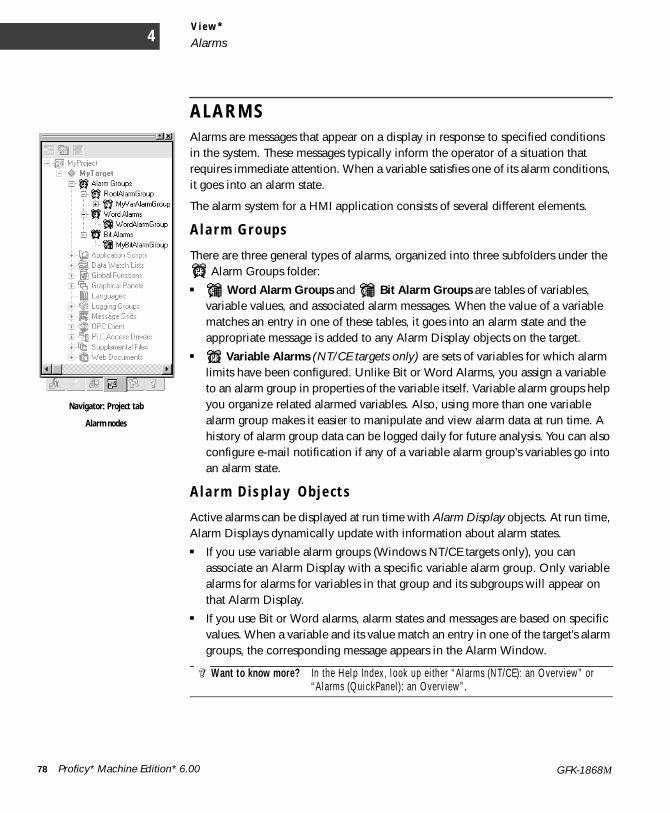
V i e w *
Alarms4
A L A R M SAlarms are messages that appear on a display in response to specified conditions in the system. These messages typically inform the operator of a situation that requires immediate attention. When a variable satisfies one of its alarm conditions, it goes into an alarm state.
The alarm system for a HMI application consists of several different elements.
A l a r m G r o u p s
There are three general types of alarms, organized into three subfolders under the Alarm Groups folder:
■ Word Alarm Groups and Bit Alarm Groups are tables of variables, variable values, and associated alarm messages. When the value of a variable matches an entry in one of these tables, it goes into an alarm state and the appropriate message is added to any Alarm Display objects on the target.
■ Variable Alarms (NT/CE targets only) are sets of variables for which alarm limits have been configured. Unlike Bit or Word Alarms, you assign a variable to an alarm group in properties of the variable itself. Variable alarm groups help you organize related alarmed variables. Also, using more than one variable alarm group makes it easier to manipulate and view alarm data at run time. A history of alarm group data can be logged daily for future analysis. You can also configure e-mail notification if any of a variable alarm group’s variables go into an alarm state.
A l a r m D i s p l a y O b j e c t s
Active alarms can be displayed at run time with Alarm Display objects. At run time, Alarm Displays dynamically update with information about alarm states.■ If you use variable alarm groups (Windows NT/CE targets only), you can
associate an Alarm Display with a specific variable alarm group. Only variable alarms for alarms for variables in that group and its subgroups will appear on that Alarm Display.
■ If you use Bit or Word alarms, alarm states and messages are based on specific values. When a variable and its value match an entry in one of the target’s alarm groups, the corresponding message appears in the Alarm Window.
Want to know more? In the Help Index, look up either “Alarms (NT/CE): an Overview” or “Alarms (QuickPanel): an Overview”.
Navigator: Project tab
Alarm nodes
78 Proficy* Machine Edition* 6.00 GFK-1868M

V i e w *Alarms
To s e t a n a l a rm c o n d i t i o n f o r Va r i a b l e A l a rms (N T/ C E ta r ge t s on l y )1. In the Variables tab of the Navigator, right-click the variable for which you want to set an alarm condition and
click Properties. The Inspector displays the variable’s properties.
2. In the Inspector, double-click the Alarming property to set the general alarm parameters (the priority of the alarm, its alarm group, and how long to keep a history of alarm events).
3. Double-click the specific type of alarm (discrete alarms, limit alarms, deviation alarms, and so on) that you want to configure to set its alarm parameters.These parameters establish the ranges that place the variable in an alarm state.
To add a Va r i a b l e A l a rm Gr oup• In the Project tab of the Navigator, under the target’s Alarm Groups folder, right-click the alarm group
to which you want to add the new group and click New. Enter a name for the new alarm group.Your new alarm group appears beneath the alarm groups node. You can now select this new alarm group when configuring properties of the target’s variables.
To add a B i t o r W ord A l a rm g r o up1. In the Project tab of the Navigator, under the target’s Alarm Groups folder, right-click the Bit Alarms or
Word Alarms folder (as appropriate) and click New.
2. Enter a name for the new alarm group.Names must be unique within a target. You can double-click the Alarm Group to edit it.
To c r e a t e a n A l a rm D i s p l ay g r aph i c a l o b j e c t1. In the Panel Editor, right-click and click Alarm.
The Alarm tool is selected.
2. Draw an Alarm Object, using the information in the Companion as a guide.
3. Right-click the Alarm Object and click Properties. The Inspector displays the object’s properties.
4. In the Inspector, edit the alarm object’s properties as desired.Windows NT/CE targets (including QuickPanel View/Control targets) and QuickPanel targets use different Alarm Display objects with similar but distinct functionality. For help on a specific property, click the property when the Companion window is open.
Proficy* Machine Edition* 6.00 79GFK-1868M

V i e w *
Logging data4
L O G G I N G D A T A(Windows NT/CE targets only.)
Logging keeps a history of data changes in your project for later analysis.
Logging groups help sort and organize your project data. By default, all data is logged using the same logging strategy. If you want variables to have different logging strategies, you can create a hierarchy of logging groups.
Logging Strategies define when data is logged for a group of variables. You can configure a group to log data periodically, on data changes, or on a condition. For example, one logging group might log data every minute, whereas another might log data every five minutes.
If you are using a Proficy Historian 2.0 (or greater) system, you can specify that logging of data from a View HMI be sent to a Historian Collector. A Collector sends data to a central Historian Server for storage and analysis. With a Collector, logging groups have no effect.
To en ab l e l o gg i ng o f a v a r i a b l e1. In the Variables tab of the Navigator, right-click a variable and click Properties.
The Inspector displays the variable’s properties.
2. Set the Enable Logging property to True.Logging is enabled for the variable, with RootLoggingGroup as the default logging group.
To add a n e w l og g i ng g r ou p1. In the Project tab of the Navigator, right-click the logging group node where you want to add the new
group, and click New.
2. Enter a name for the new logging group.Your new logging group appears beneath the logging group node.To view or edit the logging group properties, right-click it and click Properties.During Runtime, the group will log variable data according to its properties. View information about selected properties in the Companion. Click on the Tools toolbar to open the Companion if it isn’t already open.
Want to know more? In the Help Index, look up “Logging: an Overview”, “Logging Groups: an Overview, and “View Historian Collector”.
Navigator: Project tab
Logging Group nodes
80 Proficy* Machine Edition* 6.00 GFK-1868M
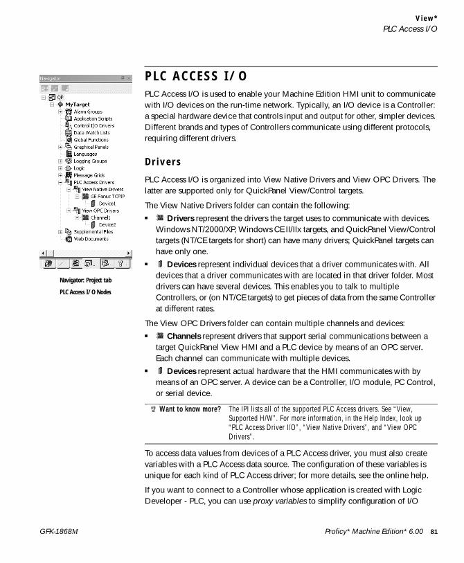
V i e w *PLC Access I/O
P L C A C C E S S I / OPLC Access I/O is used to enable your Machine Edition HMI unit to communicate with I/O devices on the run-time network. Typically, an I/O device is a Controller: a special hardware device that controls input and output for other, simpler devices. Different brands and types of Controllers communicate using different protocols, requiring different drivers.
D r i v e r s
PLC Access I/O is organized into View Native Drivers and View OPC Drivers. The latter are supported only for QuickPanel View/Control targets.
The View Native Drivers folder can contain the following:■ Drivers represent the drivers the target uses to communicate with devices.
Windows NT/2000/XP, Windows CE II/IIx targets, and QuickPanel View/Control targets (NT/CE targets for short) can have many drivers; QuickPanel targets can have only one.
■ Devices represent individual devices that a driver communicates with. All devices that a driver communicates with are located in that driver folder. Most drivers can have several devices. This enables you to talk to multiple Controllers, or (on NT/CE targets) to get pieces of data from the same Controller at different rates.
The View OPC Drivers folder can contain multiple channels and devices: ■ Channels represent drivers that support serial communications between a
target QuickPanel View HMI and a PLC device by means of an OPC server. Each channel can communicate with multiple devices.
■ Devices represent actual hardware that the HMI communicates with by means of an OPC server. A device can be a Controller, I/O module, PC Control, or serial device.
To access data values from devices of a PLC Access driver, you must also create variables with a PLC Access data source. The configuration of these variables is unique for each kind of PLC Access driver; for more details, see the online help.
If you want to connect to a Controller whose application is created with Logic Developer - PLC, you can use proxy variables to simplify configuration of I/O
Want to know more? The IPI lists all of the supported PLC Access drivers. See “View, Supported H/W”. For more information, in the Help Index, look up “PLC Access Driver I/O”, “View Native Drivers”, and “View OPC Drivers”.
Navigator: Project tab
PLC Access I/O Nodes
Proficy* Machine Edition* 6.00 81GFK-1868M

V i e w *
PLC Access I/O4
variables in the HMI target. Proxy variables are located in an HMI target and have HMI-only properties, but represent another variable on a GE Fanuc Controller target. A proxy variable’s I/O-related properties (such as its I/O address) are automatically configured based on its source variable in the Controller target.
T o a d d a V i e w n a t i v e d r i v e r t o a t a r ge t1. In the Project tab of the Navigator, expand the PLC Access Drivers node.
2. Right-click the View Native Drivers node, point to New Driver, and select a driver.The driver and a single device are added to your project and the Inspector displays the driver’s properties.
3. In the Inspector, configure the driver. If applicable, click the button in the driver’s Configuration property and enter values in the dialog box.
To add a d ev i c e t o a V i ew Na t i v e d r i v e r1. In the Project tab of the Navigator, under PLC Access Drivers and under View Native Drivers, right-click
the driver to which you want to add a new device and click New Device.The device, with a unique default name, is added to your project.
2. (Optional.) Enter a different name for the device.The Inspector displays the device’s properties. You can now edit the device's properties in the Inspector.
To add a V i ew O PC d r i v e r t o a t a r g e t1. In the Project tab of the Navigator, expand the PLC Access Drivers node.
2. Right-click the View OPC Drivers node, point to New Channel, and select a driver.The New Channel wizard appears.
3. Follow the wizard to the end, in order to configure the new channel (new driver). After you exit the wizard, the configured driver is added to your project.
To add a d ev i c e t o a V i ew OPC d r i v e r1. In the Project tab of the Navigator, under PLC Access Drivers and under View OPC Drivers, right-click the
driver to which you want to add a new device and click New Device.The New Device wizard appears.
2. Follow the wizard to the end, in order to configure the new device.After you exit the wizard, the configured device is added to your project.
Want to know more? In the Help Index, look up “Proxy Variables: an Overview”.
82 Proficy* Machine Edition* 6.00 GFK-1868M
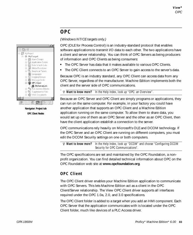
V i e w *OPC
O P C(Windows NT/CE targets only.)
OPC (OLE for Process Control) is an industry-standard protocol that enables software applications to transmit I/O data to each other. The two applications have a client and server relationship. You can think of OPC Servers as being producers of information and OPC Clients as being consumers:■ The OPC Server has data that it makes available to various OPC Clients.■ The OPC Client connects to an OPC Server to gain access to the server’s data.
Because OPC is an industry standard, any OPC Client can access data from any OPC Server, regardless of the manufacturer. Machine Edition implements both the client and the server side of OPC communications.
Because an OPC Server and OPC Client are simply programs or applications, they can run on the same computer. For example, in your factory you could have another application that supports an OPC Client and a Machine Edition application running on the same computer. To allow them to share data, you would set up one of them as an OPC Server and the other as an OPC Client, then have the client application establish a connection to the server.
OPC communications rely heavily on Microsoft’s OLE and DCOM technology. If the OPC Server and an OPC Client are running on different computers, you must edit the DCOM Security settings on one or both computers.
The OPC specifications are set and maintained by the OPC Foundation, a non-profit organization. You can find detailed technical information about OPC on the OPC Foundation web site at www.opcfoundation.org.
O P C C l i e n t
The OPC Client driver enables your Machine Edition application to communicate with OPC Servers. This lets Machine Edition act as a client in the OPC Client/Server relationship. The View OPC Client driver supports all interfaces required under the OPC 1.0a, 2.0, and 3.0 specifications.
The OPC Client folder is added to a target when you add an HMI component. Each OPC Server that the application communicates with is located under the OPC Client folder, much like devices of a PLC Access driver.
Want to know more? In the Help Index, look up “OPC: an Overview”.
Want to know more? In the Help Index, look up “DCOM” and choose “Configuring DCOM Security for OPC Communications”.
Navigator: Project tab
OPC Client Nodes
Proficy* Machine Edition* 6.00 83GFK-1868M
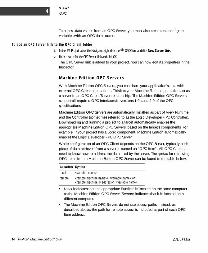
V i e w *
OPC4
To access data values from an OPC Server, you must also create and configure variables with an OPC data source.
To add a n OP C Se r v e r l i n k t o t h e O PC C l i e n t f o l d e r1. In the Project tab of the Navigator, right-click the OPC Client and click New Server Link.
2. Enter a name for the OPC Server Link and click OK.The OPC Server link is added to your project. You can now edit its properties in the Inspector.
M a c h i n e E d i t i o n O P C S e r v e r s
With Machine Edition OPC Servers, you can share your application’s data with external OPC Client applications. This lets your Machine Edition application act as a server in an OPC Client/Server relationship. The Machine Edition OPC Servers support all required OPC interfaces in versions 1.0a and 2.0 of the OPC specifications.
Machine Edition OPC Servers are automatically installed as part of View Runtime and the Controller (sometimes referred to as the Logic Developer - PC Controller). Downloading and running a project to a target automatically enables the appropriate Machine Edition OPC Servers, based on the target’s components. For example, if your project has a Logic component, Machine Edition automatically enables the Logic Developer - PC OPC Server.
While configuration of an OPC Client depends on the OPC Server, typically each piece of data retrieved from a server is named an “OPC Item”. All OPC Clients need to know how to address the data used by the server. The syntax for retrieving OPC items from a Machine Edition OPC Server can be found in the table below.
■ Local indicates that the appropriate Runtime is located on the same computer as the Machine Edition OPC Server. Remote indicates that it is located on a different computer.
■ The Machine Edition OPC Servers do not use access paths. Instead, as described above, the path for remote access is included as part of each OPC Item address.
Location Syntax
local <variable name> remote <remote machine name>\ <variable name> or
<remote machine IP address>\ <variable name>
84 Proficy* Machine Edition* 6.00 GFK-1868M
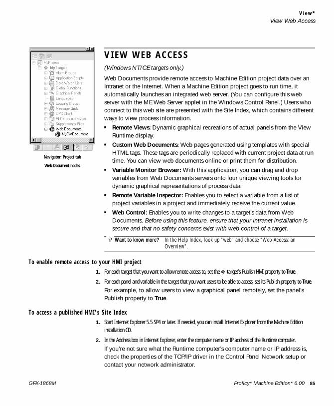
V i e w *View Web Access
V I E W W E B A C C E S S(Windows NT/CE targets only.)
Web Documents provide remote access to Machine Edition project data over an Intranet or the Internet. When a Machine Edition project goes to run time, it automatically launches an integrated web server. (You can configure this web server with the ME Web Server applet in the Windows Control Panel.) Users who connect to this web site are presented with the Site Index, which contains different ways to view process information.■ Remote Views: Dynamic graphical recreations of actual panels from the View
Runtime display. ■ Custom Web Documents: Web pages generated using templates with special
HTML tags. These tags are periodically replaced with current project data at run time. You can view web documents online or print them for distribution.
■ Variable Monitor Browser: With this application, you can drag and drop variables from Web Documents servers onto four unique viewing tools for dynamic graphical representations of process data.
■ Remote Variable Inspector: Enables you to select a variable from a list of project variables in a project and immediately receive the current value.
■ Web Control: Enables you to write changes to a target’s data from Web Documents. Before using this feature, ensure that your intranet installation is secure and that no safety concerns exist with web control of a target.
T o en a b l e r e m o t e a c c e s s t o y ou r H MI p r o j e c t1. For each target that you want to allow remote access to, set the target’s Publish HMI property to True.
2. For each panel and variable in the target that you want users to be able to access, set its Publish property to True.For example, to allow users to view a graphical panel remotely, set the panel’s Publish property to True.
To a c c e s s a p u b l i s he d HM I ’ s S i t e I nd ex1. Start Internet Explorer 5.5 SP4 or later. If needed, you can install Internet Explorer from the Machine Edition
installation CD.
2. In the Address box in Internet Explorer, enter the computer name or IP address of the Runtime computer.If you’re not sure what the Runtime computer’s computer name or IP address is, check the properties of the TCP/IP driver in the Control Panel Network setup or contact your network administrator.
Want to know more? In the Help Index, look up “web” and choose “Web Access: an Overview”.
Navigator: Project tab
Web Document nodes
Proficy* Machine Edition* 6.00 85GFK-1868M

V i e w *
View Web Access4
If you’re testing the project on the local computer, enter “localhost” (without the quotation marks) as the Address. This connects the browser to the local computer.
■ When you connect to the run time computer, the Site Index appears with a list of links to possible ways to view your process data.
■ The Site Index also includes a link to a page where you can download the Web Documents Browser. With it, you can configure graphs, tables, and ticker tapes to report on variables from several Machine Edition applications simultaneously.
To v i ew an H MI ’ s g r a ph i c a l p an e l s r emo t e l y f r om a w eb b r ows e rYou can also view graphical panels remotely from the Web Documents Site Index.
1. Start Internet Explorer 4 or later.
2. In the Address box in Internet Explorer, enter the computer name or IP address of the run time computer.The Site Index appears.
3. Click Remote Views.
4. Click the panel you want to view.After a few moments, the panel will load and run. Note that the panel must be published for you to be able to view it remotely. To publish a panel, set its Publish property to True.Because the remote viewer uses a different graphics engine to draw and update a graphical panel, there may be a few differences between the remote view of a panel and its actual appearance on an HMI. For example, trend objects on panels are not supported in remote views.
T o a d d a n e w C u s t o m W e b D o c um e n t1. In the Project tab of the Navigator, right-click the Web Documents node and click New Web Document.
2. Enter a name for your new document. Your new Custom Web Document appears beneath the Web Documents node. You can edit properties of the Custom Web Document in the Inspector.
T o ed i t a C u s t o m W e b Do c um e n t1. Outside Machine Edition, create an HTML, XML or text (txt.) document.
2. In the Project tab of the Navigator, right-click the Custom Web Document you want to edit and click Web Document Files.
3. In the Web Document Files folder that appears, place your HTML document and any logos or pictures your HTML document uses.The Web Document is created from these files when you download your project. You can view Custom Web Documents from the Site Index.
86 Proficy* Machine Edition* 6.00 GFK-1868M
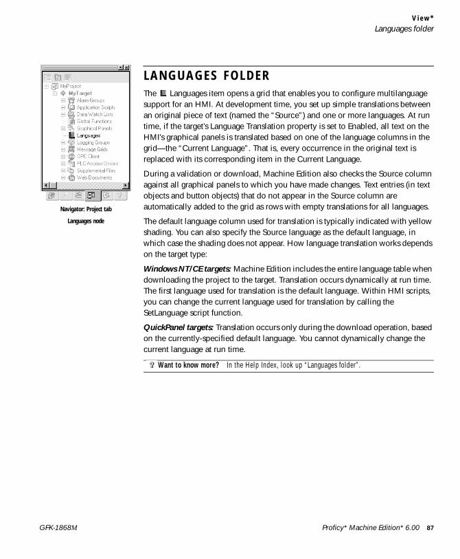
V i e w *Languages folder
L A N G U A G E S F O L D E RThe Languages item opens a grid that enables you to configure multilanguage support for an HMI. At development time, you set up simple translations between an original piece of text (named the “Source”) and one or more languages. At run time, if the target’s Language Translation property is set to Enabled, all text on the HMI’s graphical panels is translated based on one of the language columns in the grid—the “Current Language”. That is, every occurrence in the original text is replaced with its corresponding item in the Current Language.
During a validation or download, Machine Edition also checks the Source column against all graphical panels to which you have made changes. Text entries (in text objects and button objects) that do not appear in the Source column are automatically added to the grid as rows with empty translations for all languages.
The default language column used for translation is typically indicated with yellow shading. You can also specify the Source language as the default language, in which case the shading does not appear. How language translation works depends on the target type:
Windows NT/CE targets: Machine Edition includes the entire language table when downloading the project to the target. Translation occurs dynamically at run time. The first language used for translation is the default language. Within HMI scripts, you can change the current language used for translation by calling the SetLanguage script function.
QuickPanel targets: Translation occurs only during the download operation, based on the currently-specified default language. You cannot dynamically change the current language at run time.
Want to know more? In the Help Index, look up “Languages folder”.
Navigator: Project tab
Languages node
Proficy* Machine Edition* 6.00 87GFK-1868M
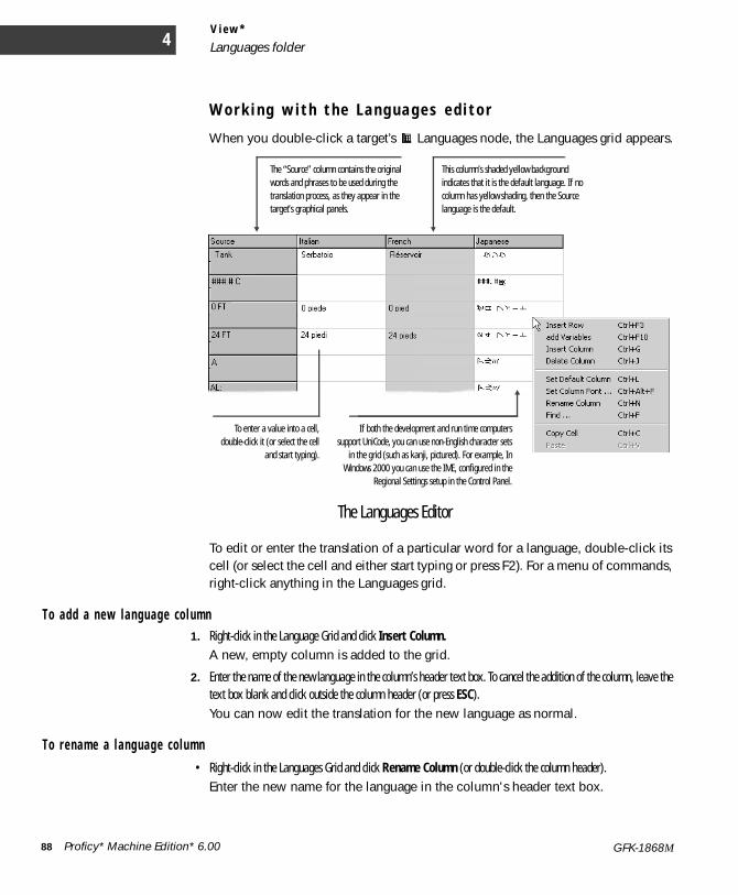
V i e w *
Languages folder4
W o r k i n g w i t h t h e L a n g u a g e s e d i t o r
When you double-click a target’s Languages node, the Languages grid appears.
To edit or enter the translation of a particular word for a language, double-click its cell (or select the cell and either start typing or press F2). For a menu of commands, right-click anything in the Languages grid.
To add a n e w l a n gu age c o l umn1. Right-click in the Language Grid and click Insert Column.
A new, empty column is added to the grid.
2. Enter the name of the new language in the column’s header text box. To cancel the addition of the column, leave the text box blank and click outside the column header (or press ESC). You can now edit the translation for the new language as normal.
T o r e nam e a l a ng uag e c o l u m n• Right-click in the Languages Grid and click Rename Column (or double-click the column header).
Enter the new name for the language in the column's header text box.
The “Source” column contains the original words and phrases to be used during the translation process, as they appear in the target’s graphical panels.
This column’s shaded yellow background indicates that it is the default language. If no column has yellow shading, then the Source language is the default.
To enter a value into a cell,double-click it (or select the cell
and start typing).
If both the development and run time computerssupport UniCode, you can use non-English character sets
in the grid (such as kanji, pictured). For example, InWindows 2000 you can use the IME, configured in the
Regional Settings setup in the Control Panel.
The Languages Editor
88 Proficy* Machine Edition* 6.00 GFK-1868M

V i e w *Languages folder
T o mo ve a l a ng uag e c o l u mn1. In the Languages Grid click and hold the header of the column you want to move.
2. Drag the mouse to the place where you want to move the column, then release the mouse button.
T o u p d a t e e n t r i e s i n t he Sou r c e c o l umn w i t h n ew tex t en t r i e s i n g r a p h i c a l p a ne l s • In the Navigator, under the target whose Languages grid you want to update, right-click the Languages node and
click Update Source Column. View searches every graphical panel in the HMI (regardless of whether or not the panel has changed since the last validation) and ensures that all text entries can be found in the Languages grid.
T o c ha nge t he d i s p l ay f o n t f o r a l a n gu age1. Right-click in the Languages grid, and click Set Column Font.
2. In the Font dialog box that appears, select the font you want to use to display the entries in the Languages grid, along with the font style and other attributes. The grid’s cells automatically resize to fit the height of the largest font used in the grid.
3. Click OK when you're done. The selected font set is used to display the translated text both in the Languages grid and (in Windows NT/CE targets) the downloaded HMI. Other font attributes—such as font sizes and styles—affect only how text appears in the grid at development time.
T o s e t t h e d e f a u l t l a n gua ge c o l u m n• In the Languages grid, right-click the column you want to set as the default language and click Set Default
Column. The yellow highlight moves to the selected column. The next time you download the project to the target with translations enabled, the default language will be used by default. Note that you can also set the Source column as the default.
T o d e l e t e a l a n gu age c o l um n f r om t h e g r i d : • In the Languages grid, right-click the column you want to remove and click Delete Column.
The column and all its translations are deleted. This operation cannot be undone. Before deleting a language, ensure that you no longer need information on translated words.
Proficy* Machine Edition* 6.00 89GFK-1868M
V i e w *
View Runtime4
V I E W R U N T I M E(Windows NT/CE and QuickPanel View/Control targets only.)
View Runtime is the program that runs your project’s completed HMI (human machine interface) on a target computer. It uses the files downloaded to the target during the download process. It is a separate application from Machine Edition; while you can start View Runtime from within Machine Edition, you do not need to be running Machine Edition to use it.
N e t w o r k i n g
View Networking provides you with the flexibility to exchange data between run time stations. Based on client-server relationships, and supporting a distributed database system, View Networking allows access to any variable or alarm group running on any other target on the computer network.
T o r un a p r o j e c t f r o m Ma ch i ne Ed i t i o n• In the Project tab of the Navigator, right-click a target and click Download and Start.
All components on the selected target are validated, downloaded to the specified computer, and View Runtime is started. Errors listed in the Build tab of the Feedback Zone must be corrected before a download can be completed. HMI components are downloaded to View Runtime while logic components are downloaded to the Controller.
T o r un a n HMI p r o j e c t o u t s i d e Ma ch i n e E d i t i o n• On the Start menu, point to Programs, GE Fanuc, and Proficy Machine Edition, and click View
Runtime.Runtime starts with the last project that was downloaded to that computer. View Runtime opens with all graphical panels configured to appear at startup (that is, all graphical panels whose Visible at Startup property is set to True).
T o i n t e r a c t w i t h V i e w R un t i meYou can configure graphical objects so that you can change variable values, trigger graphical animations, and execute custom scripts with a simple touch or click.
Want to know more? In the Help Index, look up “runtime” and choose “View Runtime: an Overview”.
Want to know more? In the Help Index, look up “networking” and choose “View Networking: an Overview”.
90 Proficy* Machine Edition* 6.00 GFK-1868M
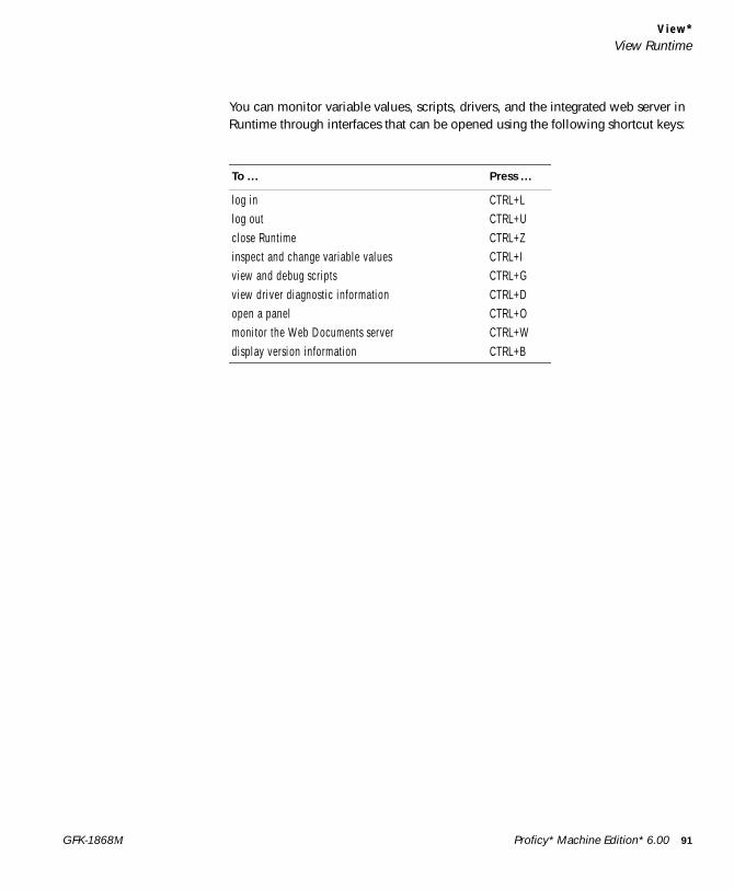
V i e w *View Runtime
You can monitor variable values, scripts, drivers, and the integrated web server in Runtime through interfaces that can be opened using the following shortcut keys:
To ... Press ...
log in CTRL+Llog out CTRL+Uclose Runtime CTRL+Zinspect and change variable values CTRL+Iview and debug scripts CTRL+Gview driver diagnostic information CTRL+Dopen a panel CTRL+Omonitor the Web Documents server CTRL+Wdisplay version information CTRL+B
Proficy* Machine Edition* 6.00 91GFK-1868M
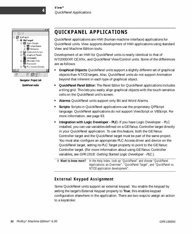
V i e w *
QuickPanel Applications4
Q U I C K P A N E L A P P L I C A T I O N SQuickPanel applications are HMI (human-machine interface) applications for QuickPanel units. View supports development of HMI applications using standard View and Machine Edition tools.
Development of an HMI for QuickPanel units is nearly identical to that of NT/2000/XP, CE II/IIx, and QuickPanel View/Control units. Some of the differences are as follows:
■ Graphical Objects: QuickPanel units support a slightly different set of graphical objects than NT/CE targets. Also, QuickPanel units do not support Animation beyond that inherent in each type of graphical object.
■ QuickPanel Panel Editor: The Panel Editor for QuickPanel applications includes a tiling grid. This lets you easily align graphical objects with the touch-sensitive cells on the QuickPanel unit’s screen.
■ Alarms: QuickPanel units support only Bit and Word Alarms.
■ Scripts: Scripts in QuickPanel applications use the proprietary QPScript language. QuickPanel applications do not support ViewScript or VBScript. For more information, see page 93.
■ Integration with Logic Developer - PLC: If you have Logic Developer - PLC installed, you can use variables defined on a GE Fanuc Controller target directly in your QuickPanel application. To use this feature, both the GE Fanuc Controller target and the QuickPanel target must be part of the same project. You must also configure an appropriate PLC Access driver and device on the QuickPanel target, setting its PLC Target property to point to the GE Fanuc Controller target. (For more information about using GE Fanuc Controller variables, see GFK-1918: Getting Started Logic Developer - PLC.)
E x t e r n a l K e y p a d A s s i g n m e n t
Some QuickPanel units support an external keypad. You enable the keypad by setting the target’s External Keypad property to True; this enables keypad configuration elsewhere in the application. There are two ways to assign an action to a keystroke:
Want to know more? In the Help Index, look up “QuickPanel” and choose “QuickPanel Applications: an Overview”, “QuickPanel Target”, and “QuickPanel vs. NT/CE application development”.
Navigator: Project tab
QuickPanel nodes
92 Proficy* Machine Edition* 6.00 GFK-1868M
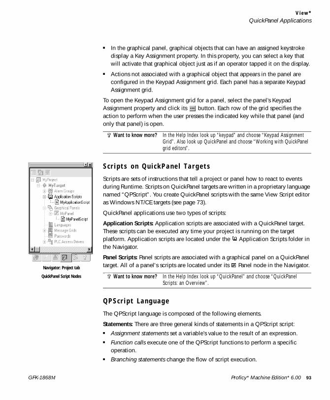
V i e w *QuickPanel Applications
■ In the graphical panel, graphical objects that can have an assigned keystroke display a Key Assignment property. In this property, you can select a key that will activate that graphical object just as if an operator tapped it on the display.
■ Actions not associated with a graphical object that appears in the panel are configured in the Keypad Assignment grid. Each panel has a separate Keypad Assignment grid.
To open the Keypad Assignment grid for a panel, select the panel’s Keypad Assignment property and click its button. Each row of the grid specifies the action to perform when the user presses the indicated key while that panel (and only that panel) is open.
S c r i p t s o n Q u i c k P a n e l T a r g e t s
Scripts are sets of instructions that tell a project or panel how to react to events during Runtime. Scripts on QuickPanel targets are written in a proprietary language named “QPScript”. You create QuickPanel scripts with the same View Script editor as Windows NT/CE targets (see page 73).
QuickPanel applications use two types of scripts:
Application Scripts: Application scripts are associated with a QuickPanel target. These scripts can be executed any time your project is running on the target platform. Application scripts are located under the Application Scripts folder in the Navigator.
Panel Scripts: Panel scripts are associated with a graphical panel on a QuickPanel target. All of a panel's scripts are located under its Panel node in the Navigator.
Q P S c r i p t L a n g u a g e
The QPScript language is composed of the following elements.
Statements: There are three general kinds of statements in a QPScript script:■ Assignment statements set a variable’s value to the result of an expression.■ Function calls execute one of the QPScript functions to perform a specific
operation. ■ Branching statements change the flow of script execution.
Want to know more? In the Help Index look up “keypad” and choose “Keypad Assignment Grid”. Also look up QuickPanel and choose “Working with QuickPanel grid editors”.
Want to know more? In the Help Index look up “QuickPanel” and choose “QuickPanel Scripts: an Overview”.
Navigator: Project tab
QuickPanel Script Nodes
Proficy* Machine Edition* 6.00 93GFK-1868M
V i e w *
QuickPanel Applications4
Keywords: The elements that make up these statements can be broken down into the following categories:■ Operators are used in mathematical expressions and conditional expressions.■ Functions are predefined routines that perform various operations in the
QuickPanel application.■ Keywords are other reserved words used in the QPScript language.
Expressions: There are two general kinds of expressions in QPScript:■ Mathematical expressions produce numerical results.■ Conditional expressions produce boolean results and are used in if-then-else
clauses.
Want to know more? In the Help Index, look up “QPScript” and choose “QPScript Language Reference”.
94 Proficy* Machine Edition* 6.00 GFK-1868M
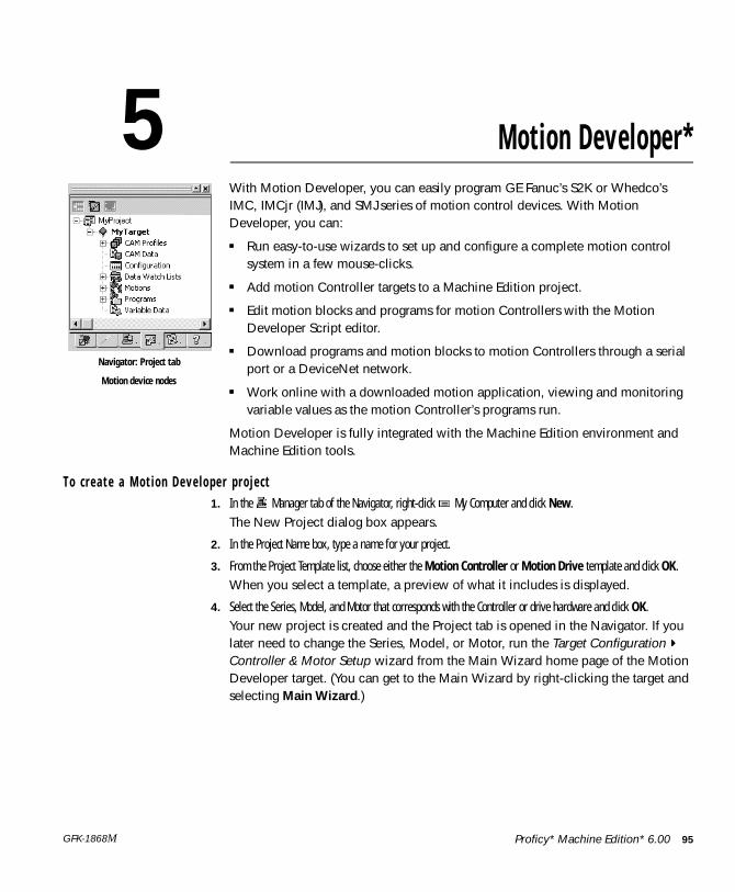
5 Motion Developer*With Motion Developer, you can easily program GE Fanuc’s S2K or Whedco’s IMC, IMCjr (IMJ), and SMJ series of motion control devices. With Motion Developer, you can:
■ Run easy-to-use wizards to set up and configure a complete motion control system in a few mouse-clicks.
■ Add motion Controller targets to a Machine Edition project.
■ Edit motion blocks and programs for motion Controllers with the Motion Developer Script editor.
■ Download programs and motion blocks to motion Controllers through a serial port or a DeviceNet network.
■ Work online with a downloaded motion application, viewing and monitoring variable values as the motion Controller’s programs run.
Motion Developer is fully integrated with the Machine Edition environment and Machine Edition tools.
T o c r e a t e a M o t i o n D e ve l o pe r p r o j e c t1. In the Manager tab of the Navigator, right-click My Computer and click New.
The New Project dialog box appears.
2. In the Project Name box, type a name for your project.
3. From the Project Template list, choose either the Motion Controller or Motion Drive template and click OK.When you select a template, a preview of what it includes is displayed.
4. Select the Series, Model, and Motor that corresponds with the Controller or drive hardware and click OK.Your new project is created and the Project tab is opened in the Navigator. If you later need to change the Series, Model, or Motor, run the Target Configuration Controller & Motor Setup wizard from the Main Wizard home page of the Motion Developer target. (You can get to the Main Wizard by right-clicking the target and selecting Main Wizard.)
Navigator: Project tab
Motion device nodes
Proficy* Machine Edition* 6.00 95GFK-1868M
M o t i o n D e v e l o p e r *
About Motion Developer5
A B O U T M O T I O N D E V E L O P E RYou use Motion Developer to develop motion applications on Windows-based computers. Motion applications are loosely defined as a series of motion device targets with programs, motion blocks, and configuration data. These applications can then be downloaded to the motion Controller hardware, either directly (through the computer’s serial port) or through a DeviceNet network.
In general, you go through the following phases when developing a motion application:
1. Create a new Machine Edition project.
2. Add a Motion Controller or Motion Drive target to the project, depending on the kind of motion device.
3. On each target, create the configuration script and (if appropriate) the programs and motion blocks for the motion Controller or drive. The Motion Wizards (see page 102) can make this easy.
4. Validate and download the application to the motion Controller.
The Motion Expert wizard takes you through these items step by step.
S u p p o r t e d m o t i o n c o n t r o l d e v i c e s
Motion Developer supports the following lines of motion control devices.
For more information, visit www.gefanuc.com.
Communication between the development computer and motion control devices is supported over the COM port and over DeviceNet networks.
GE Fanuc motion control devices S2K Controller/drive devicesS2K drive-only devices
Whedco motion control devices IMC motion ControllersIMCjr (IMJ) motion ControllersSMJ drives
96 Proficy* Machine Edition* 6.00 GFK-1868M
M o t i o n D e v e l o p e r *Motion Applications
M O T I O N A P P L I C A T I O N SA typical Motion application consists of a single target. However, your project can have as many targets as you want.
M o t i o n t a r g e t s
A Motion target represents a run-time destination motion device that you program and configure from Machine Edition. You need a separate target for each physical motion device you configure, whether it’s a Controller or a drive-only device.
When adding a Motion target, you specify either a Controller or a Drive target. This determines the models of Controller you can select in its Controller Type property.■ Drive targets represent drive-only motion devices. This includes GE Fanuc S2K
drive-only devices and Whedco SMJ devices. These targets have a Configuration script only (page 98).
■ Controller targets represent Controller/drive motion devices. This includes GE Fanuc S2K Controller/drive devices and Whedco IMC and IMCjr (IMJ) devices. These targets have a Configuration script (page 98), Motion Programs (page 99), and can have several Motion Blocks (page 100). In addition, they can make use of a CAM Profile (page 108).
To ed i t c o n f i g u r a t i o n s c r i p t s , mo t i o n p r o g r a ms , a n d mo t i o n b l o c k s1. In the Project tab of the Navigator, under the motion target, right-click Configuration, or the motion
program or motion block you want to edit and click Open.
2. Create or edit the program in the appropriate editor.
3. After editing an item, download the program or project to the target hardware.
Proficy* Machine Edition* 6.00 97GFK-1868M
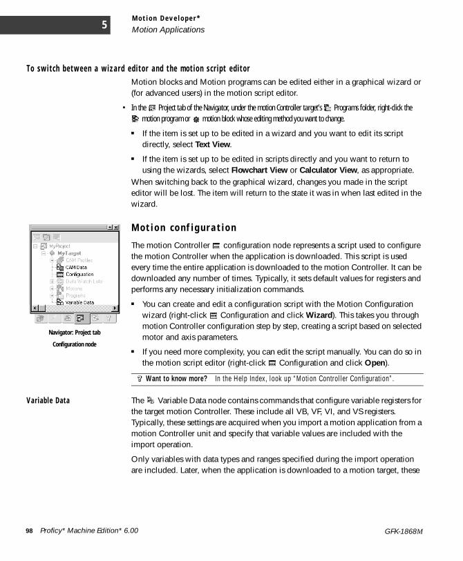
M o t i o n D e v e l o p e r *
Motion Applications5
T o sw i t c h b e t we e n a w i z a r d e d i t o r a n d t h e m o t i o n s c r i p t e d i t o rMotion blocks and Motion programs can be edited either in a graphical wizard or (for advanced users) in the motion script editor.
• In the Project tab of the Navigator, under the motion Controller target’s Programs folder, right-click the motion program or motion block whose editing method you want to change.
■ If the item is set up to be edited in a wizard and you want to edit its script directly, select Text View.
■ If the item is set up to be edited in scripts directly and you want to return to using the wizards, select Flowchart View or Calculator View, as appropriate.
When switching back to the graphical wizard, changes you made in the script editor will be lost. The item will return to the state it was in when last edited in the wizard.
M o t i o n c o n f i g u r a t i o n
The motion Controller configuration node represents a script used to configure the motion Controller when the application is downloaded. This script is used every time the entire application is downloaded to the motion Controller. It can be downloaded any number of times. Typically, it sets default values for registers and performs any necessary initialization commands.
■ You can create and edit a configuration script with the Motion Configuration wizard (right-click Configuration and click Wizard). This takes you through motion Controller configuration step by step, creating a script based on selected motor and axis parameters.
■ If you need more complexity, you can edit the script manually. You can do so in the motion script editor (right-click Configuration and click Open).
Var i ab l e Data The Variable Data node contains commands that configure variable registers for the target motion Controller. These include all VB, VF, VI, and VS registers. Typically, these settings are acquired when you import a motion application from a motion Controller unit and specify that variable values are included with the import operation.
Only variables with data types and ranges specified during the import operation are included. Later, when the application is downloaded to a motion target, these
Want to know more? In the Help Index, look up “Motion Controller Configuration”.
Navigator: Project tab
Configuration node
98 Proficy* Machine Edition* 6.00 GFK-1868M
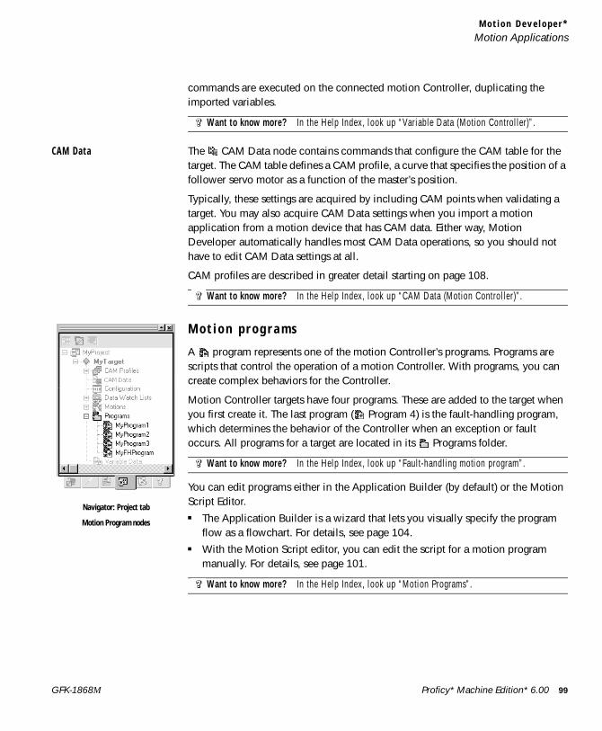
M o t i o n D e v e l o p e r *Motion Applications
commands are executed on the connected motion Controller, duplicating the imported variables.
CAM Data The CAM Data node contains commands that configure the CAM table for the target. The CAM table defines a CAM profile, a curve that specifies the position of a follower servo motor as a function of the master’s position.
Typically, these settings are acquired by including CAM points when validating a target. You may also acquire CAM Data settings when you import a motion application from a motion device that has CAM data. Either way, Motion Developer automatically handles most CAM Data operations, so you should not have to edit CAM Data settings at all.
CAM profiles are described in greater detail starting on page 108.
M o t i o n p r o g r a m s
A program represents one of the motion Controller’s programs. Programs are scripts that control the operation of a motion Controller. With programs, you can create complex behaviors for the Controller.
Motion Controller targets have four programs. These are added to the target when you first create it. The last program ( Program 4) is the fault-handling program, which determines the behavior of the Controller when an exception or fault occurs. All programs for a target are located in its Programs folder.
You can edit programs either in the Application Builder (by default) or the Motion Script Editor.■ The Application Builder is a wizard that lets you visually specify the program
flow as a flowchart. For details, see page 104.■ With the Motion Script editor, you can edit the script for a motion program
manually. For details, see page 101.
Want to know more? In the Help Index, look up “Variable Data (Motion Controller)”.
Want to know more? In the Help Index, look up “CAM Data (Motion Controller)”.
Want to know more? In the Help Index, look up “Fault-handling motion program”.
Want to know more? In the Help Index, look up “Motion Programs”.
Navigator: Project tab
Motion Program nodes
Proficy* Machine Edition* 6.00 99GFK-1868M
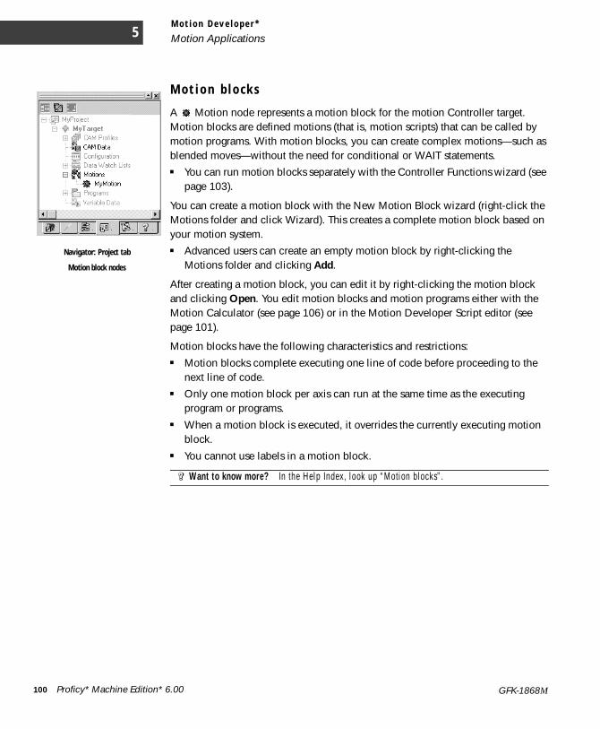
M o t i o n D e v e l o p e r *
Motion Applications5
M o t i o n b l o c k s
A Motion node represents a motion block for the motion Controller target. Motion blocks are defined motions (that is, motion scripts) that can be called by motion programs. With motion blocks, you can create complex motions—such as blended moves—without the need for conditional or WAIT statements.■ You can run motion blocks separately with the Controller Functions wizard (see
page 103).
You can create a motion block with the New Motion Block wizard (right-click the Motions folder and click Wizard). This creates a complete motion block based on your motion system.■ Advanced users can create an empty motion block by right-clicking the
Motions folder and clicking Add.
After creating a motion block, you can edit it by right-clicking the motion block and clicking Open. You edit motion blocks and motion programs either with the Motion Calculator (see page 106) or in the Motion Developer Script editor (see page 101).
Motion blocks have the following characteristics and restrictions:■ Motion blocks complete executing one line of code before proceeding to the
next line of code.■ Only one motion block per axis can run at the same time as the executing
program or programs.■ When a motion block is executed, it overrides the currently executing motion
block.■ You cannot use labels in a motion block.
Want to know more? In the Help Index, look up “Motion blocks”.
Navigator: Project tab
Motion block nodes
100 Proficy* Machine Edition* 6.00 GFK-1868M
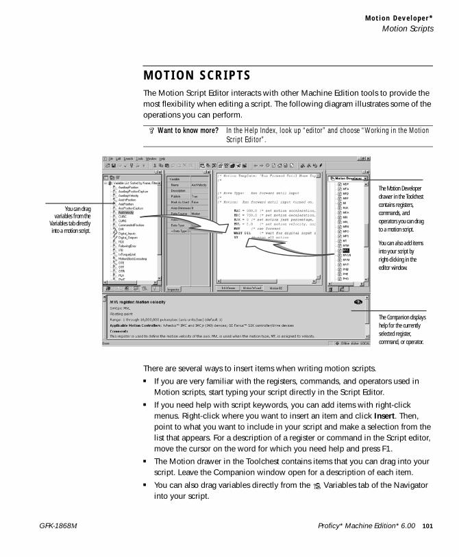
M o t i o n D e v e l o p e r *Motion Scripts
M O T I O N S C R I P T SThe Motion Script Editor interacts with other Machine Edition tools to provide the most flexibility when editing a script. The following diagram illustrates some of the operations you can perform.
There are several ways to insert items when writing motion scripts.■ If you are very familiar with the registers, commands, and operators used in
Motion scripts, start typing your script directly in the Script Editor.■ If you need help with script keywords, you can add items with right-click
menus. Right-click where you want to insert an item and click Insert. Then, point to what you want to include in your script and make a selection from the list that appears. For a description of a register or command in the Script editor, move the cursor on the word for which you need help and press F1.
■ The Motion drawer in the Toolchest contains items that you can drag into your script. Leave the Companion window open for a description of each item.
■ You can also drag variables directly from the Variables tab of the Navigator into your script.
Want to know more? In the Help Index, look up “editor” and choose “Working in the Motion Script Editor”.
The Motion Developer drawer in the Toolchest contains registers, commands, and operators you can drag to a motion script.
You can also add items into your script by right-clicking in the editor window.
You can dragvariables from the
Variables tab directlyinto a motion script.
The Companion displays help for the currently selected register, command, or operator.
Proficy* Machine Edition* 6.00 101GFK-1868M
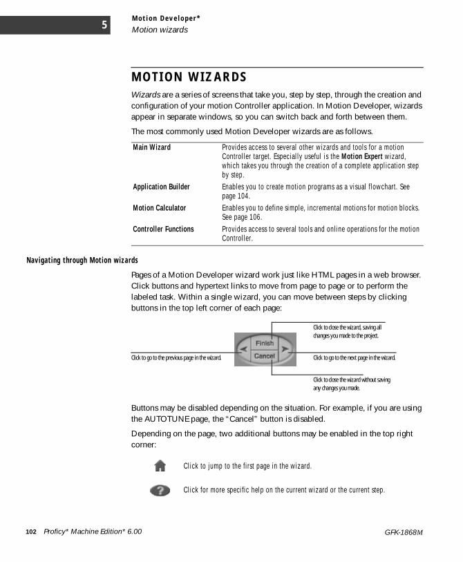
M o t i o n D e v e l o p e r *
Motion wizards5
M O T I O N W I Z A R D SWizards are a series of screens that take you, step by step, through the creation and configuration of your motion Controller application. In Motion Developer, wizards appear in separate windows, so you can switch back and forth between them.
The most commonly used Motion Developer wizards are as follows.
Nav iga t i ng th r ough Mot ion wiza rds
Pages of a Motion Developer wizard work just like HTML pages in a web browser. Click buttons and hypertext links to move from page to page or to perform the labeled task. Within a single wizard, you can move between steps by clicking buttons in the top left corner of each page:
Buttons may be disabled depending on the situation. For example, if you are using the AUTOTUNE page, the “Cancel” button is disabled.
Depending on the page, two additional buttons may be enabled in the top right corner:
Main Wizard Provides access to several other wizards and tools for a motion Controller target. Especially useful is the Motion Expert wizard, which takes you through the creation of a complete application step by step.
Application Builder Enables you to create motion programs as a visual flowchart. See page 104.
Motion Calculator Enables you to define simple, incremental motions for motion blocks. See page 106.
Controller Functions Provides access to several tools and online operations for the motion Controller.
Click to jump to the first page in the wizard.
Click for more specific help on the current wizard or the current step.
Click to close the wizard, saving all changes you made to the project.
Click to close the wizard without saving any changes you made.
Click to go to the next page in the wizard.Click to go to the previous page in the wizard.
102 Proficy* Machine Edition* 6.00 GFK-1868M
M o t i o n D e v e l o p e r *Motion wizards
Many wizard pages contain tables of parameters. Edit the parameters based on your system needs, then click Next. When editing parameters, you can also do the following:
■ Click Use Last Saved Values to revert back to the last values saved for this wizard page. Click Use Default Values to fill in parameters with default or calculated values.
■ Click a parameter’s button (to the right of its entry text box) for a short description, including its minimum, maximum, and default values. Click the
button for a more detailed description of that parameter.
Wizards for different targets, motions, and programs open in separate windows. You can switch between windows by clicking the tabs at the bottom of the editor window display.
Two of the most important wizards are the Main Wizard and the Controller Functions/Drive Functions wizard:
■ The Main Wizard page provides access to most other major Motion Developer wizards and tools. This includes the Motion Expert wizard, which takes you through the creation of a complete Motion Developer project step by step. To open the Main Wizard page for a target, right-click the target and select Main Wizard.
■ With the Controller Functions and Drive Functions wizards, you can perform diagnostic and other operations on the motion Controller. Functions on these wizards have no effect if the local computer is not connected to a motion Controller. To access these wizards, double-click the target you want to perform the functions on or, while working with a target, click the Controller/Drive Functions button.
Want to know more?■For a description of the wizards available from the Main Wizard page, in the Help Index,
look up “Main Wizard page”.■For a description of features available from the Controller Functions wizard page, in the
Help Index, look up “Controller Functions wizard”.
Proficy* Machine Edition* 6.00 103GFK-1868M
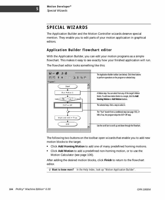
M o t i o n D e v e l o p e r *
Special Wizards5
S P E C I A L W I Z A R D SThe Application Builder and the Motion Controller wizards deserve special mention. They enable you to edit parts of your motion application in graphical editors.
A p p l i c a t i o n B u i l d e r f l o w c h a r t e d i t o r
With the Application Builder, you can edit your motion programs as a simple flowchart. This makes it easy to see exactly how your finished application will run.
The flowchart editor looks something like this:
The following two buttons on the toolbar open wizards that enable you to add new motion blocks to the target.■ Click Add Homing Motion to add one of many predefined homing motions.■ Click Add Motion to add a predefined non-homing motion, or to use the
Motion Calculator (see page 106).
After adding the desired motion blocks, click Finish to return to the flowchart editor.
Want to know more? In the Help Index, look up “Motion Application Builder”.
The Application Builder toolbar (see below). Click these buttons to perform operations on the program or selected step.
A Motion step. You can select from any of the target’s Motion blocks. To add new motion blocks to a target, click the Add Homing Motion or Add Motion buttons.
The selected step. Click a step to select it.
The “True” branch from a conditional step (see page 105). If MB is True, the program skips the DO7=Off step.
Use the scroll bar to scroll up and down through the flowchart.
104 Proficy* Machine Edition* 6.00 GFK-1868M

M o t i o n D e v e l o p e r *Special Wizards
Bas i c f l owcha r t s tep types The flowchart is composed of the following basic step types.■ Start and End steps: Flowchart execution begins at the Start step. When
execution reaches the End step, the program stops.■ Logic steps: Performs a logic-oriented action, such as setting or resetting a
particular register.■ Motion Program steps: Performs a motion program action, such as starting or
stopping a program.■ Motion block steps: Runs a motion block.■ Delay steps: Pauses program execution. ■ Conditional and Connector steps: Evaluates a given condition and branches
execution depending on the results. For more details, see Conditional Steps on page 105 (or look up “Connecting and disconnecting conditional steps” in the online help).
■ User-defined steps: Performs a piece of motion script entered by you.■ Remark steps: Enables you to insert a comment into the flowchart. Remarks are
included in the script downloaded to the motion Controller.■ Comment steps: Enables you to insert a comment into the flowchart. Comments
are not included in the script downloaded to the motion Controller.
Conditional steps are described in greater detail below.
Cond i t i ona l s t eps Conditional steps represent a simple conditional statement. When program execution reaches a conditional step, it branches depending on a specified expression:
■ If the expression is True, execution branches to the right (indicated by a “T”).■ If the expression in the statement is False, execution branches downward.
You can choose from several conditional expressions, including several that refer to fault registers. Selecting a conditional step or connector highlights the line connecting it to its partner.
Want to know more? In the Help Index, look up “Application Builder step types”.
Steps here are executed only if FI = 0 (that is, if the expression is false).
Proficy* Machine Edition* 6.00 105GFK-1868M
M o t i o n D e v e l o p e r *
Special Wizards5
To i n s e r t a n ew s t ep i n t o t he App l i c a t i o n Bu i l d e r f l o wc ha r t1. In the Application Builder flowchart, select the step immediately preceding the spot where the new step will go.
To add a step to the beginning of the flowchart, select the Start step.
2. Click the Add Command button on the Application Builder toolbar.In the menu that appears, point to the type of command or step you want to add, then select the exact step from the submenu. Connector steps, Comments, and User-defined steps are found under the Standard Elements option.Some command types may be unavailable depending on your project. For example, you cannot add a Motion step until the target has some motion blocks.
3. The new step appears after the originally selected step.If necessary, you can move the step to a different position, or (if appropriate) edit the step’s parameters.
To ed i t a s t e p i n t h e Ap p l i c a t i o n Bu i l d e r f l ow cha r t• In the Application Builder, do one of the following:
■ Double-click the step.
- or -
■ Right-click the step and choose Edit (if the step is editable).
- or -
■ Select the step, then click Edit Command on the Application Builder toolbar.
- or -
■ Select the step, then press CTRL+E.Only certain steps have parameters that can be edited. If a selected step cannot be edited, the Edit Command button is disabled.
M o t i o n C a l c u l a t o r
The Motion Calculator is the default editor for motion blocks. With it, you can create simple incremental motion blocks based on mathematical calculations, viewing the results of changes as you make them.
You can open the Add Motion wizard by right-clicking the Motions folder in the Navigator and clicking Wizard. Unless you configure a motion block to be edited as text, the Motion Calculator also opens when you right-click a motion block and click Open.
106 Proficy* Machine Edition* 6.00 GFK-1868M
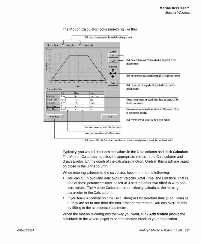
M o t i o n D e v e l o p e r *Special Wizards
The Motion Calculator looks something like this:
Typically, you would enter desired values in the Data column and click Calculate. The Motion Calculator updates the appropriate values in the Calc column and draws a velocity/time graph of the calculated motion. Units in this graph are based on those in the Units column.
When entering values into the calculator, keep in mind the following:■ You can fill in two (and only two) of Velocity, Total Time, and Distance. That is,
one of these parameters must be left at 0 and the other two filled in with non-zero values. The Motion Calculator automatically calculates the missing parameter in the Calc column.
■ If you leave Acceleration time (Acc. Time) or Deceleration time (Dec. Time) as 0, they are set to one-third the total time for the motion. You can override this by filling in the appropriate parameter.
When the motion is configured the way you want, click Add Motion (above the calculator in the wizard page) to add the motion block to your application.
Click one of these to select the kind of motion you want.
Click these buttons to zoom in and out of the graph of the plotted motion.
Click the arrows to pan around the graph of the plotted motion.
Click here to print the graph of the plotted motion on the default printer.
You can enter values for two of these three parameters. (The third is calculated.)
Enter new values for Acceleration time and Deceleration Time to override the defaults.
Click here to clear all values for the current motion.
Calculated values appear in the Calc column.
Enter your own values in the Data column.
Click here to fill in the Calc column and view (or update) a velocity/time graph of the calculated motion.
Proficy* Machine Edition* 6.00 107GFK-1868M
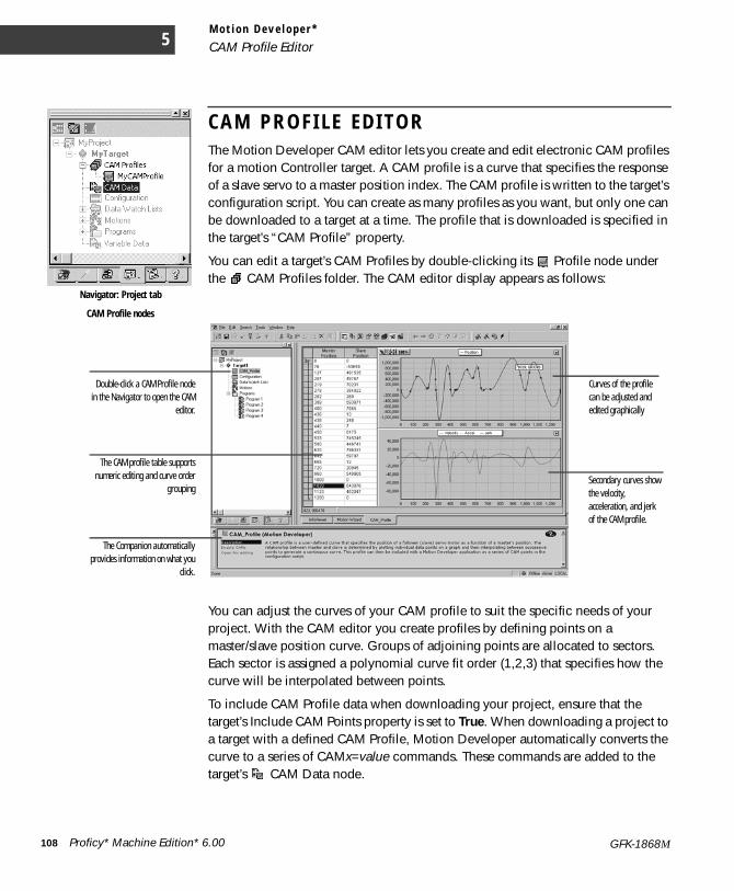
M o t i o n D e v e l o p e r *
CAM Profile Editor5
C A M P R O F I L E E D I T O RThe Motion Developer CAM editor lets you create and edit electronic CAM profiles for a motion Controller target. A CAM profile is a curve that specifies the response of a slave servo to a master position index. The CAM profile is written to the target’s configuration script. You can create as many profiles as you want, but only one can be downloaded to a target at a time. The profile that is downloaded is specified in the target’s “CAM Profile” property.
You can edit a target’s CAM Profiles by double-clicking its Profile node under the CAM Profiles folder. The CAM editor display appears as follows:
You can adjust the curves of your CAM profile to suit the specific needs of your project. With the CAM editor you create profiles by defining points on a master/slave position curve. Groups of adjoining points are allocated to sectors. Each sector is assigned a polynomial curve fit order (1,2,3) that specifies how the curve will be interpolated between points.
To include CAM Profile data when downloading your project, ensure that the target’s Include CAM Points property is set to True. When downloading a project to a target with a defined CAM Profile, Motion Developer automatically converts the curve to a series of CAMx=value commands. These commands are added to the target’s CAM Data node.
Navigator: Project tab
CAM Profile nodes
Curves of the profile can be adjusted and edited graphically
Secondary curves show the velocity, acceleration, and jerk of the CAM profile.
The CAM profile table supportsnumeric editing and curve order
grouping
The Companion automaticallyprovides information on what you
click.
Double-click a CAM Profile nodein the Navigator to open the CAM
editor.
108 Proficy* Machine Edition* 6.00 GFK-1868M
M o t i o n D e v e l o p e r *CAM Profile Editor
The number of CAMx commands added to the configuration script depends on the target’s CAM Point Resolution property.■ If CAM point Resolution is 1 degree, 360 CAM commands are added to the
script.■ If CAM point Resolution is 0.1 degrees, 3600 CAM commands are added to the
script.
Downloading 3600 CAM commands can be very time-consuming. It is therefore recommended that you use a Resolution of 1 degree, at least during the initial development stages.
To add a n e w CA M Pr o f i l e t o a mo t i o n C on t r o l l e r t a r ge t1. In the Project tab of the Navigator, right-click the motion Controller target’s CAM Profiles folder and
click New Profile.A new Profile appears under the CAM Profiles folder.
2. Enter a new name for the Profile.You can now open the profile in the CAM Editor. Note that only one CAM profile can be downloaded to a motion Controller at a time.
T o ed i t a CA M p ro f i l e o n a m o t i o n Con t r o l l e r t a r ge t• In the Project tab of the Navigator, under the motion Controller target’s CAM Profiles folder, right-click
the Profile you want to edit and click Open Profile (or just double-click the Profile).The CAM editor opens with the target’s CAM profile.For more details on using the profile editor, look up “Editing a Motion CAM Profile” in the online help.
T o s p e c i f y t h e CAM P ro f i l e t ha t g e t s d ow n l oa d e d t o t h e m o t i o n C on t r o l l e r t a r g e t1. In the Project tab of the Navigator, right-click the motion Controller target for which you want to select a
CAM Profile and click Properties.The Inspector displays the CAM profile’s properties.
2. If necessary, in the Inspector, set the target’s Include CAM point property to True.This ensures that Machine Edition includes CAM profile data the next time you download the application to the motion Controller.
3. In the Inspector, select the desired CAM Profile in the target’s CAM Profile property.This property appears only if Include CAM point is set to True. You can select from all CAM Profiles configured for the target.
Want to know more? In the Help Index, look up “Motion Developer CAM Editor: an Overview”.
Proficy* Machine Edition* 6.00 109GFK-1868M


IndexAactions 43, 44Active scripting 75adding
alarm groups (Bit and Word) 79CAM Profiles 109Control I/O drivers 61custom web documents 86language columns 88logging groups 80logic component 38Machine Edition projects 18OPC server links 84panels 70PLC Access drivers 82
alarm groups 78alarms 78
Alarm Display objects 78alarm groups 78Bit Alarms 78setting alarm conditions 79Variable Alarms 78Word Alarms 78
Allen-Bradley RIO 60animation
graphical objects 71touch animation scripts 73
Application Builderabout 104conditional steps 105inserting steps 106See alsosteps, flowchart
application scripts 73, 76, 93applications, motion 97ASCII drivers 60authorization. See product authorization
Bbacking up projects 18Bit Alarms 78blocks, motion. See motion blocksblue arrows. See docking markersbranches 44
Build tab 24
CCalculator, Motion See Motion CalculatorCAM data 99, 108CAM point resolution 109CAM Profiles
specifying for download 109CAM profiles
about 108adding 109editing 109editor 108
CE box. See CE targetsCE targets 27, 30
downloading 34client
networking 90OPC 83
Companion 16, 44, 48, 51, 54component
logic 38conditional steps 105configuration
CAM data 99motion script 98variable data 98
configuringalarm conditions 78Control I/O 62Controller 64panels 70PLC Access I/O 81properties 20user preferences 19
Control I/O 61tool 61working with 62
Controller 63configuring 64going online 29going online (IL) 49going online (ST) 52running 65scan cycle 63
Controller Functions wizard 103controller/drive targets, motion 97correcting, errors 33creating
actions 44alarm display objects 79
Proficy* Machine Edition* 6.00 111GFK-1868M
alarm groups (Variable) 79application scripts 73FBDs 53IL blocks 47macros 40panel scripts 73projects 18, 30, 69SFCs 40ST blocks 50subroutines 44touch animation scripts 74variables 31
custom web documents 86adding 86editing 86
DData Watch 45debugging scripts 91developing. See creatingDeviceNet 60devices
adding to PLC Access driver 82motion control 96PLC Access 81
docking markers 17downloading 29, 32, 33, 64
CE targets 34motion device targets 33NT targets 33specifying CAM profile for 109
drawing graphical objects 71drawing tools 71Drive Functions wizard 103drive targets, motion 97drivers
addingControl I/O 61PLC Access I/O 82
ASCII 60Control I/O 60, 61Control Peer 60OPC Client 83PLC Access I/O 81
Eediting
application scripts 73
CAM profiles 109custom web documents 86FBDs
offline 54online 56
IL blocksoffline 48, 49
ladder programsoffline 44online 45
motion scripts 101panel scripts 73panels 71quick editing
ladder program 45SFCs 41
quick test 35SFCs
offline 40online 42
steps, flowchart 106structured text
offline 51online 52
editorsfunction block diagram (FBD) 53grid (QuickPanel) 77instructin list (IL) 47instruction list (IL) 50ladder 43panel 70script 73, 93structured text (ST) 50
errors and warningscorrecting 33Feedback Zone 24
external keypad 92
FFactory Client 2000. See CE targetsFBD Editor
offline 54online 56
FBD instructions 54inserting from the FBD editor 55inserting from the Toolchest 55
FBD text boxesinserting from the FBD editor 55
112 Proficy* Machine Edition* 6.00 GFK-1868M

inserting from the Toolchest 54FBDs
creating 53editing 54, 56opening 53
Feedback Zone 24fixing, project errors 33flowchart editor See Application Builderflowchart steps See steps, flowchartfull-text search 15Function Block Diagram (FBD) Editor 53
GGE Fanuc Genius 60getting help 15global function library scripts 73graphical objects 70
animating 71drawing 71
graphical panels. See Panelsgrid editor
keypad assignment 92messages 72
Hhardware
motion devices 96Hardware Key Authorization 5help 15Historian Collector 80
II/O
configuringControl 62PLC Access 82
Control 61OPC 83
IEC addresses 62IL blocks
creating 47editing 48, 49opening 47
IL Editoroffline 48, 49
Import tab 24index, search 15
Indexed Image Display (IID) 72Indexed Message Display (IMD) 72InfoView tab 18InfoViewer 16inserting
FBD instructions 54FBD instructions (FBD editor)) 55FBD instructions (Toolchest) 55FBD text boxes (FBD editor) 55FBD text boxes (Toolchest) 54IL instructions 48ladder instructions 44motion script items 101rungs 44script functions 76SFC instructions 41ST instructions 51
Inspector 20installing Machine Edition 4Instructin List (IL) Editor 47Instruction List (IL) Editor 50Internationalization. See Languages folder
Kkeypad assignment 92keyword search 15
Llabels 43Ladder Editor 43
offline 44online 45
ladder instructions 44ladder programs
defined 43editing
offline 44online 45
opening 43quick editing 45
Language translation 87Languages 87Languages folder 87
adding new languages 88grid 88moving language columns 89renaming languages 88
Languages grid 88
Proficy* Machine Edition* 6.00 113GFK-1868M
default language 89delete language 89display font 89updating Source language 89
locatinglabels 43variables 40, 44, 48, 51, 54
logging data 80enabling logging for a variable 80
logging groups 80adding 80
logging strategies 80Logic Developer
PC 37 to ??Logic Developer - PC 37 to ??logic, adding 38
MMachine Edition
downloading 33environment 14getting help 15key features 15 to 25OPC servers 84projects 18, 27properties 20toolbars 17validating 33
macros 40Main Motion Wizard 103Manager tab 18message grids 72messages 72
Indexed Image Display (IID) 72Indexed Message Display (IMD) 72Triggered Message Display (TMD) 72
Messages tab 24Modicon Quantum 800 60Motion applications
configuration script 98programs 99
motion applications 97motion blocks
about 100editing with calculator 106opening 97switching editors 98
Motion Calculator
about 106using 107
motion configuration 98opening 97
Motion Developerapplications 97supported hardware 96
Motion programsfault-handing program 99opening 97switching editors 98
motion programs 99motion scripts 101motion targets 97Motion Wizards
about 102Application Builder 104Controller Functions 103Drive Functions 103Main Wizard 103navigating through 102parameters 103See also Motion Calculatorspecial wizards 104
moving product authorization 7multi-language support. See Languages folder
NNavigator 18
property column view. See Property column viewnetworking 90NT computers. See NT targetsNT targets 27, 30
downloading 33
Oobjects. See graphical objectsoffline
FBD Editor 54IL Editor 48, 49Ladder Editor 44SFC Editor 40ST Editor 51
onlineFBD Editor 56Ladder Editor 45SFC Editor 42ST Editor 52
114 Proficy* Machine Edition* 6.00 GFK-1868M
to the Controller 29to the Controller (IL) 49to the Controller (ST) 52
online help 15OPC 83
client 83server links 83, 84servers 84
openingapplication scripts 73FBDs 53IL blocks 47ladder programs 43macros 40motion blocks, motion programs, and motion
configuration 97panel scripts 73panels 70projects 19, 28, 30, 38, 69, 95SFCs 40ST blocks 50
Options tab 19options, user preferences 19
PPanel Editor 70
animation 71graphical objects 70working with 71
panel scripts 73, 76, 93panels 70
configuring 70editing 71opening 70quick testing 35
parameters, Motion Wizards 103peer driver, control 60phrase search 15PLC Access I/O 81preview panels. See quick testProduct Authorization 5product authorization
authorizing Machine Edition 6moving to another PC 7
Proficy Historian 2.0 80profiles, CAM See steps, flowchartprograms, motion See motion programsProject tab 19
ProjectsShared 27
projects 18backing up 18creating 30downloading 33Motion Developer 95opening 19, 28, 30, 38, 69, 95running 28, 90sharing between Machine Edition workstations 27validating 33with HMI component 69with logic component 38
properties 20configuring 25
Property column view 25Property Inspector. See Inspectorproxy variables 81
QQPScript language 93quick editing
ladder program 45SFCs 41
quick start 12quick test, panels 35QuickPanel
scripts 93QuickPanel Applications 92QuickPanel Grid Editor 77
RReferences tab 24remote views 86Reports
variable 26Reports tab 24requirements, hardware and software 2resolution, CAM point 109rungs 43
inserting 44write changes 46
runningController 65projects 28, 90sample applications 28View Runtime 90
Proficy* Machine Edition* 6.00 115GFK-1868M
Ssample applications 28scan cycle, Controller 63script commands. See script functionsScript Editor 73, 93
inserting script functions 76scripts 73, 93working with 76
script functions 76scripting languages
Active scripting 75QPScript 93VBScript 74ViewScript 74
scripts 73, 93application scripts 73, 93debugging 91global function library scripts 73inserting script functions 76motion 101panel scripts 73, 93touch animation scripts 73
scripts, motioninserting items 101
search, full-text 15search, index 15Sequential Function Charts. See SFCsservers
networking 90OPC 84
setting. See configuringSFC Editor
offline 40online 42
SFC instructions, inserting 41SFCs
editing 40opening 40quick editing 41
Shared Projects 27shortcut keys, View Runtime 90shunts 44Site Index 85Smart Lists 22Software Key 6ST blocks
creating 50opening 50
ST Editor
offline 51online 52
ST instructionsinserting 51
steps, flowchartconditional 105editing 106inserting 106step types 105
structured textediting 51, 52
Structured Text (ST) Editor 50subroutines 44switching editors, motion blocks and motion programs 98system requirements 2
Ttags. See variablestargets 27, 30
motion 97testing
panels 35scripts 91
toolbarsdrawing tools 71ladder instruction tools 44Machine Edition tools 17
Toolchest 23, 44, 54tools
Companion 16Control I/O 61Data Watch 45docking markers 17Feedback Zone 24InfoViewer 16Inspector 20Navigator 18overview 14toolbars 17Toolchest 23, 44, 54
touch animation scripts 73translations. See Languages folderTriggered Message Display (TMD) 72
UUnused Variable report 26user preferences 19
Vvalidating 24, 33, 64Variable
property column view 25Variable Alarms 78variable data 98Variables 25
managing 25reports 26
variablescreating 31locating 40, 44, 48, 51, 54proxy 81watching values 56
Variables tab 19, 25VBScript language 75View 69 to 94
testing the HMI 35View Runtime 90
running 90shortcut keys 90
ViewScript language 74
WWarm Standby 65
and OPC servers 68configuring 66, 67configuring OPC server for 68
watching variable values 56Web Access 85
Site Index 85Windows CE targets. See CE targetsWindows NT targets. See NT targetswindows. See Panelswizard, Controller Functions 103wizard, Drive Functions 103Wizard, Main 103wizards, motion See Motion WizardsWord Alarms 78word search 15writing motion scripts 101writing scripts 76
Proficy* Machine Edition* 6.00 117GFK-1868M

118 Proficy* Machine Edition* 6.00 GFK-1868M