profiform 200 profiform 320
TRANSCRIPT
Profiform 200 Profiform 320 Operating manual

Profiform 200 / Profiform 320 Operating manual Page 1
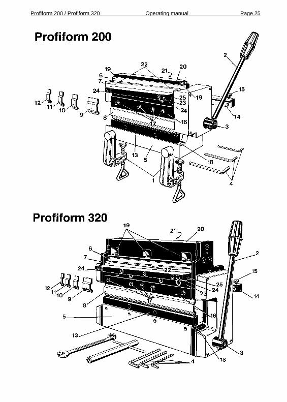
Table of contents 1. General information Page 2 2. Profile of the Profiform sheet metal working machines Page 2 3. Technical data Page 3 4. Safety information Page 3 5. Operating limits Page 3 6. Unpacking and assembling the machine Page 4 6.1. Assembling the Profiform 200 Page 4 6.2. Assembling the Profiform 320 Page 4 7. Cutting Page 6 8. Bending Page 12 9. Adjusting cutter play Page 17 10. Reversing the cutters Page 18 11. Maintenance Page 18 12. Accessories Page 19 12.1. Stamping tools Page 19 12.2. Notching tool Page 20 12.3. Stamping tool holder Page 20 12.4. Cutter end stop Page 21 12.5. Vent slots/grooves Page 21 12.6. Bending tools/prisms Page 21 12.7. Boxing tools Page 22 12.8. Bending limitation Page 22 12.9. Mounting plate for Profiform 320 Page 24 12.10. Multi purpose table for Profiform 200/320 Page 24 Illustration Profiform 200: Page 25 Illustration Profiform 320: Page 25 The illustration on page 25 of the manual can be used as a reference when reviewing the operating manual.
Profiform 200 / Profiform 320 Operating manual Page 2
1. General information We congratulate you on the purchase of your Profiform sheet metal working machine. This machine will open up unimaginably many possibilities in the area of sheet metal working. With proper use, the machine will provide you with reliable service over the years. Profiform machines are patented quality products manufactured in Switzerland. This operating instructions manual must be thoroughly and carefully read before the machine is used for the first time! The figures that appear in parentheses ( ) in the text refer to corresponding numbers in the illustrations. 2. Profile of the Profiform sheet metal working machines The Profiform 200 and 320 machines were designed as small sheet metal working centers for the processing of fine gage sheet metal (see Section 3). Among other things, they are particularly characterized by the following features: - compact design - sturdy all-metal construction - wide range of possible uses in the areas of electronics, model building,
prototype building, schools, jewellery manufacturing, etc. - multiple applications for cutting, bending, stamping* and punching*
various materials (*See Section 12. „Accessories”) - clean and practically burr-free cuts as the result of a precise cutting
device - precise bending of parts thanks to good accessibility and double
bending prism - minimal maintenance

Profiform 200 / Profiform 320 Operating manual Page 3
3. Technical data Profiform 200 Profiform 320 Overall length 270 mm 423 mm Width 95 mm 125 mm Height 163 mm 254 mm Gross weight basic equipment 7.3 kg 15.8 kg Usable maximum cutting length 200 mm 320 mm Usable maximum bending length 200 mm 320 mm Maximum stamping pressure 15’000 N 20’000 N Maximum material thickness See Section 5. „Operating limits” 4. Safety information This operating instructions manual must be thoroughly and carefully read before the machine is used for the first time! The machine must first be mounted on a firm and solid work surface before being used! (See Section 6.) No adjustments are to be made to, or functions performed on, the machine unless it is firmly attached to a workbench! Sheet metal can be very sharp-edged. In order to avoid injuries, it is necessary that care be taken. It is recommended that leather gloves be worn when working with sheet metal. 5. Operating limits Maximum material thickness Bending Cutting
Aluminium sheet metal (Al 99.5%) 1.5 mm 1.5 mm Brass sheet metal, semi-hard 1.0 mm 1.0 mm Copper sheet metal, semi-hard 1.0 mm 1.0 mm Tinplate sheet metal 1.0 mm 1.0 mm Printed circuit boards (GRP) - 1.5 mm The larger bending prism must be used to bend sheet metal of 0.8 mm thickness or more. Maximum permissible manual force for stamping: 300 N In no way are the operating limits stated above to be exceeded; otherwise, damage to the machine can occur.

Profiform 200 / Profiform 320 Operating manual Page 4
6. Unpacking and assembling the machine Profiform Machines are delivered packed in a cardboard box and protected by a styrofoam capsule. Because of its weight, the machine must be unpacked on a rigid table or workbench. The package contents can be checked against the information printed on the carton. All parts are easy to unpack. 6.1. Assembling the Profiform 200
2 mounting clamps (1) are supplied with the Profiform 200. Using these clamps, firmly secure the machine on the edge of a rigid table or workbench. The machine is provided with 2 holes for the mounting clamps in the base (5) of the machine. See the Profiform 200 illustration for clamp position. Then assemble the hand lever (2) per the Profiform 200 illustration. The hand lever is inserted into the hole provided for it and firmly tightened by means of the hex socket head screw (3). The hex socket head screw must engage the countersink provided in the hand lever in order to ensure that the hand lever does not slip when operated. Tighten the hex socket head screw with the corresponding allen wrench (4) supplied with the machine.
6.2. Assembling the Profiform 320
Securely mount the Profiform 320 on the edge of a rigid table or workbench using two M8 screws and two large O.D. washers. For this purpose, there are two M8 attaching threads in the machine base (5).
The length of the required M8 screws is determined as follows: table top thickness + washer thickness + 44 mm = screw length. Round off to the next higher 5 mm.
Example: Table top thickness 41 mm Washer thickness 2 mm +44 mm 44 mm Total 87 mm
Rounding off to the next higher 5 mm gives 90 mm. Accordingly, two 90 mm long M8 screws and two 2 mm thick washers having a large O.D. are used.

Profiform 200 / Profiform 320 Operating manual Page 5
After selecting the location for the machine, drill two 9 to 10 mm holes, space 250 mm apart, in the top of the worktable. The holes must both be the same distance from the edge of the table. This distance can be between 50 and 60 mm. See sketch below. Top view of the table:
250 mm
50 to 60 mm distance from edge of table
ø9...10 mm dia. holes
Front edge of work bench
Now firmly screw down the machine from below by means of the two screws with washers. The screws are inserted through the tabletop and the two holes in the cover plate - visible from below - and tightly secured in the machine base (5). If the Profiform 320 is not mounted permanently at one place, then the optional mounting plate must be used. This allows mounting at various locations by means of commercially available screw clamps (See Section 12.9.). As the last step, attach the hand lever (2) as shown in the Profiform 320 illustration. It is inserted in the hole provided and tightened by means of the hex socket head screw (3). The hex socket head screw must engage the countersink in the hand lever in order to assure non-slip assembly of the hand lever. Tighten the hex socket head screw with the corresponding allen wrench (4) provided with the machine.

Profiform 200 / Profiform 320 Operating manual Page 6
7. Cutting Plate material is cut between the upper cutter (6) and the lower cutter (7). Clean, straight, i.e., so-called burr-free, cuts are ensured when cutter play is correctly set and the proper procedures followed. The following work examples illustrate the procedure for bending. Proper initial practice is required to thoroughly familiarize yourself with the machine’s functions. Work example: Single cut
Planned trim edge
- Using a pencil or a scribe, mark the desired trim edge on the workpiece.
Scribed trim edge
- To open the cutter fixture, move the hand lever (2) towards you until
contacting the end stop. - Slide the material, with the scribed side up, into the narrow slot directly
below the upper cutter (6). This can be done from the front or the rear of the machine.
- Position the scribed line precisely at the front lower cutting edge of the upper cutter (6).
- Using your left hand, securely hold the workpiece in this position. - With your right hand, move the hand lever (2) rearward until the cut is
completed.

Profiform 200 / Profiform 320 Operating manual Page 7
Finished workpiece
Trimmed off section Work example: Four right-angle cuts
1st cut
2nd cut
3rd cut
4th cut
- Scribing of the first trim edge on the workpiece.
1st trim edge

Profiform 200 / Profiform 320 Operating manual Page 8
- Open the cutting fixture by moving the hand lever (2) forward until it
contacts the end stop. - Slide the workpiece, with the scribed side up, into the narrow slot
directly below the upper cutter (6). This can be done from the front or the rear.
- Position the scribed mark precisely at the front lower cutting edge of the upper cutter (6).
- Using your left hand, securely hold the workpiece in this position. - With your right hand, move the hand lever (2) rearward until the cut is
completed.
Workpiece
Trimmed off
section
- Remove the trimmed workpiece from the machine and discard the
trimmed off section (away from the cutters). - Again open the cutting fixture by moving the hand lever forward until
reaching the end stop. - Scribing of the second trim edge on the workpiece.
Scribed 2nd cut - From the rear of the machine, slide the workpiece into the narrow slot
directly below the upper cutter and position the first trimmed edge against the left side stop (machine frame) of the cutting fixture.

Profiform 200 / Profiform 320 Operating manual Page 9
- Position the scribed mark precisely at the front lower cutting edge of the
upper cutter (6). - With your left hand, firmly press and hold the workpiece against the left-
side stop. - With your right hand, move the hand lever (2) rearward until the cut is
completed. Workpiece
Trimmed off section
- Remove the trimmed workpiece from the machine and discard the
trimmed off section (away from the cutters). - Again open the cutting fixture by moving the hand lever forward until it
reaches the end stop. - Scribing of the third trim edge on the workpiece.
Scribed 3rd cut - From the rear of the machine, slide the workpiece into the narrow slot
directly below the upper cutter and position the first trimmed edge against the left side stop (machine frame) of the cutting fixture.
- Position the scribed mark precisely at the front lower cutting edge of the upper cutter (6).

Profiform 200 / Profiform 320 Operating manual Page 10
- Using your left hand, firmly press and hold the workpiece against the
left-side stop. - With your right hand, move the hand lever (2) rearward until the cut is
completed.
Trimmed off section
Workpiece
- Remove the trimmed workpiece from the machine and discard the
trimmed off section (away from the cutters). - Again open the cutting fixture by moving the hand lever forward until it
reaches the end stop. - Scribing of the fourth trim edge on the workpiece. Scribed 4th cut
- From the rear of the machine, slide the workpiece into the narrow slot
directly below the upper cutter and position the first trimmed edge against the left side stop (machine frame) of the cutting fixture.
- Position the scribed mark precisely at the front lower cutting edge of the upper cutter (6).
- Using your left hand, firmly press and hold the workpiece against the left-side stop.
- With your right hand, move the hand lever (2) rearward until the cut is completed.

Profiform 200 / Profiform 320 Operating manual Page 11
Trimmed off section
Workpiece - Remove the trimmed workpiece from the machine and discard the
trimmed off section (away from the cutters). Finished workpiece
- The workpiece now has 4 edges that are at right angles to each other. Note: If numerous parts of the same trimmed size are required, the use of the optionally available stop for cutting is recommended (See Section 12.4.). The parts can then be appropriately positioned against the left- side stop (machine frame) and the stop for cutting as described above. This assures right-angularity without the need for scribing.

Profiform 200 / Profiform 320 Operating manual Page 12
8. Bending Bending of sheet metal is accomplished between the bending tool (8) and the bending prism (13). All materials thinner than 0.8 mm should be bent using the narrow V- shaped prism. All materials thicker than 0.8 mm must be bent using the wide V-shaped prism. As such, the bending prism can be used in two ways. - Pick up the bending prism and the bend end stop. - The end stop (14) can be adjusted by loosening the clamp screw (15) - Adjust the end stop by measuring establishing depth of bend A with a
scale. Dimension A corresponds to the inside depth of the desired bent flange. Dimension A is shorter than dimension B by an amount equal to ½ of the prism width.
- Re-tighten the end stop by means of the clamp screw. Dimension determination example: B
A1/2 prism width
- Move hand lever rearward to the end position. - From the rear of the machine, insert the bending prism (13) in the slot
provided for it. - Insert the required bending tool(s) (8/9/10/11/12) in the slot behind the
clamping bar (16), position it as required, press it against the end stop surface with your hand, and secure it by means of the hex socket head screws (17).

Profiform 200 / Profiform 320 Operating manual Page 13
- To achieve good results, the bending tool should be as long as or
longer than the length of the required bend. - Insert the workpiece between the bending prism and the bending tool
and position it flush against the end stop (14). - Move hand lever forward until the bending process begins. - Remove your hands from the workpiece. - Continue the bending process by moving the hand lever forward until
the desired angle is reached. - Move the hand lever rearward until reaching the end stop. - Remove finished workpiece from the machine. Work example: Right angle
- Trim the workpiece to the required size. (See Section 7. „Cutting”). - Install the required bending tool(s) (8,9,10,11,12) in the machine. - Remove the bending prism (13) together with end stop fixture (14) and
select the V-shaped prism side that is appropriate for the material thickness.
Selected prism side

Profiform 200 / Profiform 320 Operating manual Page 14
- Mount the bend stop fixture (14) so that the selected prism side is
pointing up. - Adjust the bend stop (per dimension example on page 12) to the
required depth of bend. - Move the hand lever rearward until reaching the end stop. - From the rear of the machine, position the prism and stop fixture in the
groove (18) provided in the machine base (5). - From the front of the machine, slide the workpiece between the bending
tool and the prism and into the machine and position it flush against the end stop (14).
Workpiece
- Move hand lever forward until the bending process begins. - Remove your hands from the workpiece. - Continue the bending process by moving the hand lever forward until
the desired angle is reached.
- Move the hand lever rearward until reaching the end stop. - Remove the finished workpiece from the machine.

Profiform 200 / Profiform 320 Operating manual Page 15
Note: If short flange depths are desired, the cut stop can be installed reversed as per the sketch below.
Short flange depth
Still shorter flange depths are possible by using the cutting fixture to trim off the individual flanges of the finished L-section. Work example: U-channel
- Bending of the first right angle per work example „Right Angle”. - Adjust the end stop for the required depth for the inside dimension of
the U-channel. This dimension must be at least equal to the thickness of the bending tool, i.e., >= 5 mm. For this procedure, the material thickness must be added to the dimension, since the already bent flange is positioned against the end stop.
- From the front of the machine, slide the workpiece between the bending tool and the prism and into the machine and position the already bent flange flush against the end stop.

Profiform 200 / Profiform 320 Operating manual Page 16
Workpiece
- Move the hand lever forward until the bending process begins. - Remove your hands from the workpiece. - Continue the bending process by moving the hand lever forward until
the required angle is reached. Workpiece Shorten as required
- Move the hand lever rearward until reaching the end stop. - Remove the workpiece from the machine.

Profiform 200 / Profiform 320 Operating manual Page 17
9. Adjusting cutter play The lower cutter (7) moves practically play-free in front of the upper cutter (6). Cutter play is adjusted and checked on each machine before they leave the plant. Normally, cutter play need not be readjusted. However, if the cutters are reversed (per Section 10.), or if high cutting forces or excessive burring should occur during cutting, then the cutter play must be readjusted. Correct adjustment of cutter play is very important for achieving the desired results. The procedure for adjusting cutter play must be carefully followed point by point: - Back out the mounting screws (19) of upper cutter (6) by one complete
turn. - Loosen the locknuts (21) at the rear of the cutter holder (20). The
cutter holder itself must not be loosened! - Loosen the small hex socket head screws (21), located at the rear of
the cutter holder, by one complete turn. - Using your hands, apply pressure across the entire width of the upper
cutter and push it back. - Move the hand lever (2) all the way to the rear. The lever must be left
in this position until the adjustment procedure is completed! - Tighten the mounting screws (19) of the upper cutter very lightly. - Alternately turn the small hex socket head screws (21) at the rear of the
cutter holder inward by small amounts, until the upper cutter (6) and the lower cutter (7) make minute contact along their entire length.
- Now firmly tighten the mounting screws (19) of the upper cutter and then the locknuts (21) behind the cutter holder (20).
- Move the hand lever forward to the end stop. - Carefully move the hand lever to the rear. If the upward movement of
the lower cutter is obstructed by the upper cutter, the hex socket head screws behind the cutter holder were turned in too far. In that case, move the hand lever forward and repeat the adjustment procedure from the beginning. The adjustment is satisfactory when a light resistance is noticed when moving the lower cutter along the length of the upper cutter. The adjustment of cutter play is now complete.
Note: Cutter play is optimal when a standard sheet of typewriter paper can be cut along the entire length of the cutters. Continue the adjustment procedure until achieving this condition!
Profiform 200 / Profiform 320 Operating manual Page 18
10. Reversing the cutters After many cutting operations, the cutters slowly become dull. However, this only occurs after several thousand cuts if sheet metal within the specified limits of operation has been processed and the machine properly utilized. Because each cutter has four sharp cutting edges, they can be reversed as follows: - Move the hand lever forward to the end stop and leave it there. - Completely remove the mounting screws (19) of the upper cutter (6). - Remove the upper cutter, rotate it to the next sharp cutting edge and
reinstall it. - Re-insert the mounting screws (19), press the cutter completely to the
rear and tighten the screws. - Now completely remove the mounting screws (22) of the lower cutter
(7). - Remove the lower cutter, rotate it to the next sharp cutting edge and
reinstall it. - Re-insert the mounting screws (22), press the cutter to the front until it
makes contact and tighten the screws. - Now carefully adjust cutter play per Section 9.! 11. Maintenance The Profiform sheet metal working machine has been designed for minimal maintenance. The two following points describe how to keep the machine operating reliably and in good condition even after a long time in service. After using the machine, wipe off the steel parts with an oily cloth so as to prevent any rust from forming. This is particularly important for those steel parts not surface protected. With frequent use of the machine, lightly lubricate the guides at each side of the slide (23) with high viscosity oil once a week. If the machine is not frequently used, lubricate after every usage.
Profiform 200 / Profiform 320 Operating manual Page 19
12. Accessories There is a wide variety of accessories available that allow you to use your Profiform sheet metal working machine to its fullest potential and perform certain steps even more easily. Unless otherwise noted, the accessories are for use in conjunction with Profiform 200 and Profiform 320.
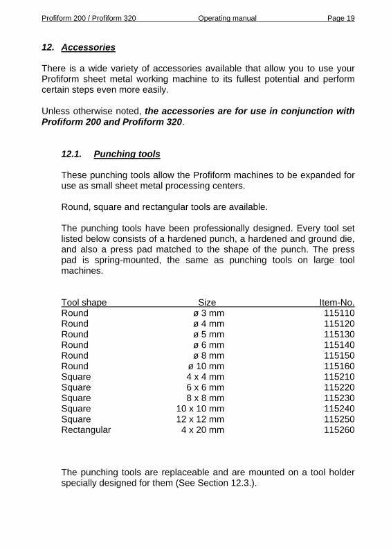
12.1. Punching tools These punching tools allow the Profiform machines to be expanded for use as small sheet metal processing centers. Round, square and rectangular tools are available. The punching tools have been professionally designed. Every tool set listed below consists of a hardened punch, a hardened and ground die, and also a press pad matched to the shape of the punch. The press pad is spring-mounted, the same as punching tools on large tool machines. Tool shape Size Item-No. Round ø 3 mm 115110 Round ø 4 mm 115120 Round ø 5 mm 115130 Round ø 6 mm 115140 Round ø 8 mm 115150 Round ø 10 mm 115160 Square 4 x 4 mm 115210 Square 6 x 6 mm 115220 Square 8 x 8 mm 115230 Square 10 x 10 mm 115240 Square 12 x 12 mm 115250 Rectangular 4 x 20 mm 115260 The punching tools are replaceable and are mounted on a tool holder specially designed for them (See Section 12.3.).

Profiform 200 / Profiform 320 Operating manual Page 20
12.2. Notching tool The notching tool consists of hardened punch and a hardened die with integrated punch guide. It has been designed so that corners of any dimension from 1 x 1 mm to 70 x 70 mm (up to 100 x 100 mm with the Profiform 320) can be notched out, as well as any square or rectangular sizes in-between. Dimensions up to 12 x 12 mm can be notched out in a single operation, and larger dimensions in a number of steps. The tool is not sensitive to lateral forces. As in the case of the punching tools, it can be replaced and is mounted to the punching tool holder (See Section 12.3.). Item-No.: Notching tool 115270 12.3. Tool holder for punching tools The tool holder for punching tools is required for mounting the punching tools and the notching tool (See Sections 12.1. and 12.2.). It has an adjustable depth stop and an adjustable side stop to allow identical stampings in the case of a series of parts.
Fine adjustment (optional)
Tool holder for punching tools
Item-No.: Tool holder for punching tools 115100 Fine adjustment 115102

Profiform 200 / Profiform 320 Operating manual Page 21
12.4. Cutter end stop The cutter end stop is a great help where a series of identical parts are manufactured. It also usually eliminates the need to scribe the parts. The cutter end stop is inserted in one of the mounting holes (24) and secured to the machine by means of the stud screw provided and the threading (25). Range of adjustment is variable from 0 mm to 95 mm. Item-No.: Cutter end stop for Profiform 200 and 320 115400 Cutter end stop whole machine width for Profiform 200 115420 Cutter end stop whole machine width for Profiform 320 115432 12.5. Vent slots/grooves Special tools for fabricating vent slots and grooves are available as an additional feature for expanding the possible uses of your Profiform sheet metal working machine. Tool Size (LxWxH) Item-No. Vent slot 34x1.5x3.0 mm 115310 Vent slot 34x2.5x5.0 mm 115320 Groove/reinforcement rib 34x1.0x1.0 mm 115340 A special tool holder is required to use the above vent slot and groove tools. Item-No.: Tool holder 115300
12.6. Bending tools/prisms For special applications, it makes sense to have additional bending punches or prisms. Note: The bending tools and prisms can be milled, filed and ground. If a specific radius is needed for a given bending operation, this can be accomplished by using a properly modified bending tool.

Profiform 200 / Profiform 320 Operating manual Page 22
The basic equipment already includes a set of bending tools. But in addition to them, the following are also available individually:
Tool Length Item-No. Bending tool 320 mm 115009 Bending tool 200 mm 115008 Bending tool 40 mm 115004 Bending tool 20 mm 115003 Bending tool 15 mm 115002 Bending tool 10 mm 115001 Bending prism 320 mm 115011 Bending prism 200 mm 115010 12.7. Boxing tools Boxing tools are used to completely fold sheet metal 180 degrees. They are used in two operations. In the first operation, the sheet metal is bent to approximately 110 to 120 degrees. In the second operation, it is folded to 180 degrees. The boxing tool sets consist of 3 tools each and have a functional length of 200 mm for the version for Profiform 200, and 320 mm for the version for Profiform 320. Boxed constructions are used for thin sheet metal as a means of reinforcement or wherever a sharp edge must be avoided. Item-No.: Boxing tool set, version for Profiform 200 115600 Boxing tool set, version for Profiform 320: 115700
12.8. Bending limitation The bending limitation is an adjustable device that allows to obtain any desired bending angle in-between 0 and 90 degrees and to fabricate an unlimited number of similar parts with exactly the same bending angle. This useful device is standard equipment on later Profiform 200 machines. On Profiform 320 machines it is an accessory which can be mounted anytime, as all the necessary drillings and threads are already incorporated in the machine body.

Profiform 200 / Profiform 320 Operating manual Page 23
Bending limitation for Profiform 200 Item No: 115800
Bending limitation P200
Bending limitation for Profiform 320 Item No: 115900
Bending limitation P320

Profiform 200 / Profiform 320 Operating manual Page 24
12.9. Mounting plate for Profiform 320 If it is not possible to permanently mount the Profiform 320, the machine can be bolted to a mounting plate. The machine can then be fastened to a workbench with commercially available large screw clamps. When the machine is not being used, it can be stored with the mounting plate still attached, and the workbench can be used for other purposes. The necessary mounting screws are included with the mounting plate, but not the screw clamps. Item-No.: Mounting plate for P320 115500 12.10. Multi-purpose table for Profiform 200/320 The multi-purpose table is a useful accessory with the function of a third hand. For accurate cutting and bending operations the multi purpose table and the angular stop are very helpful accessories. Item-No.: Table for P200 115550 Table for P320 115560 Angular stop for table 115570
Profiform 200 / Profiform 320 Operating manual Page 25

Profiform 200 / Profiform 320 Operating manual Page 26
Copyright: Profiform AG 2004 Copying or distributing of the entire contents or of parts of the contents of this manual is only permitted with the written agreement of the publisher. Copying for personal use is permitted.