profile control (love) 012613 - 5counties.org · rock ramps/chutes & pools/cascades 44 in...
TRANSCRIPT

Profile Control
Michael Love, P.E.
Tools for Aquatic Organism Passage
Replacement/RemovalRetrofit New
Tech
nica
l Fi
shw
ay
Baffl
es
Na
tura
lBe
d
Rest
ored
Prof
ile
Roug
hene
dC
hann
el
Dro
p St
ruct
ures
Unco
ntro
lled
Regr
adeFish Passage
Approach
Stream CrossingProject
Profile Control
Increasing Ecological Function
Geomorphic ApproachesHydraulic Approaches

3
Profile Control Options
Slope Pros / Cons
Restored Profile
Limited by channel type
+ Passage diversity, Habitat
- Scale/cost
Roughened Channel
Durability, bedload limit
+ Passage diversity
- Species, failure risk
Boulder Weirs<5%
+ Passage diversity, Habitat
- Failure risk
Rigid Weirs(log, concrete) <5%
+ Rigid, durable
- Species, habitat
Technical Fishway 10% or
“vertical”
+ Small footprint
- Species specific, flow, sediment, debris
Design Profiles for Incised Channels: Replacement
Design Profile: Stream Simulation with Uncontrolled Regarde (headcutting)
Design Profile: Forced Profile(rock weirs, roughened channel…)
Design Profile: Combined Forced Profile & Stream Simulation
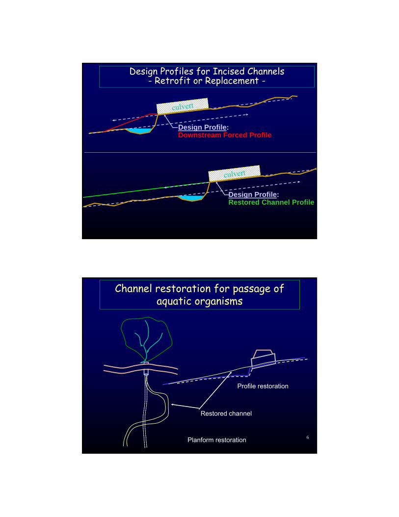
Design Profiles for Incised Channels- Retrofit or Replacement -
Design Profile:Downstream Forced Profile
Design Profile:Restored Channel Profile
6
Channel restoration for passage of aquatic organisms
Planform restoration
Profile restoration
Restored channel

Profile Restoration
From Christine Chann, San Pedro Creek Watershed Coalition
Restored 1,300 feet of incised channel:• Stabilized Banks • Created Instream and Riparian Habitat • Eliminated a Culvert Barrier
From Christine Chann, San Pedro Creek Watershed Coalition
Profile Restoration

From Christine Chann
• Sloped-back banks to reduced entrenchment
• Raised channel bed as much as 8 feet using native and imported fill
• Increase bankfull width by 20% and built floodplains
• Installed profile control to force riffles and pool
From Syd TempleProfile Restoration
10
Channel restoration for fish passage correction
Constructed 2000Photos from 2005
Profile RestorationOutlet Creek
Photos from Kozmo Bates

11
Upstream of CulvertNo Incision Experienced
Profile RestorationOutlet Creek
Downstream of Project Channel Remains Incised
Photos from Kozmo Bates
Site 10 was constructed as a spanner racked additional wood. Looking downstream and aggradation is along right bank.
Wood Count: 93 total wood fractions (Volume: 60.9 cubic meters)17 large trees with rootwads, 69 large logs, 3 medium logs, 4 bunches of “small wood debris” (aka slash)
From Joe’l Benegar & Rocco Fiori 12

From Joe’l Benegar & Rocco Fiori 13
From Joe’l Benegar & Rocco Fiori 14
Before
After
15
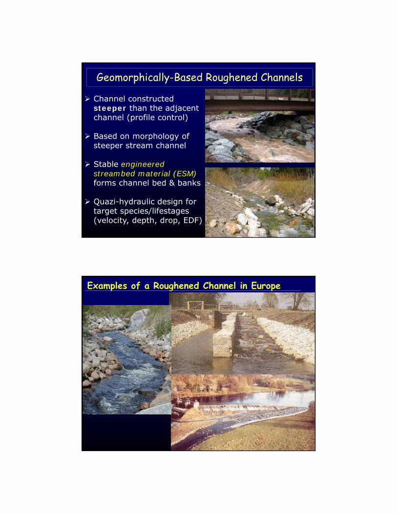
Geomorphically-Based Roughened Channels
Channel constructed steeper than the adjacent channel (profile control)
Based on morphology of steeper stream channel
Stable engineered streambed material (ESM)forms channel bed & banks
Quazi-hydraulic design for target species/lifestages(velocity, depth, drop, EDF)
Examples of a Roughened Channel in Europe

3% - 1%10%- 3%30%-10%
Source Transport Response
InitiationScour
Deposition
Large Woody DebrisLarge and immobile,
traps sedimentMobile, transports
with sediment
>20% 2% - 0.1% < 0.1%Slope:
(from Montgomery and Buffington, 1993)
Generalized Stream Classification
17
Natural Steep Stream MorphologySteep Boulder-Cobble Stream Channels
Plane-bed
Step-Pool
Cascades

Natural Step Pool Stream Morphology
Step Pool Stream Channels
Geomorphically-Based Roughened Channel ConceptCommon Channel Types
Roughened Riffles
Plane Bed Channel (rock ramps)
Rapids or Chutes & Pools
Step-Pools
Cascades & PoolIncr
easi
ng S
lope
Caution:
Only use channel types & slopes that the target species/lifestage are known to ascend
Risk increases further the roughened channel characteristics deviates from the natural channel(i.e. slope, bed material, entrenchment) 20

Plane-Bed (Rock Ramp) Roughened Channels
Grub Creek “Rock Ramp”
Slope & Length Thresholds:
Slope Range: < 4%
Max Head Diff.: 5 feet
Use chutes and Pools for Larger Head Differentials
Bed Morphology:
Random placement of rock
D100 < Channel Depth
21
Woodacre Creek at San Geronimo Valley Road
Before
2 Years After

Plane-Bed (Rock Ramp) Roughened ChannelsFish Passage Pros:
Doesn’t rely on leaping abilities
Large amount of hydraulic diversity at all flows
Cons:
Shallow depths at low flows
High flow passage often limited by turbulence
Rock RampCulvert Outlet Pool (Energy Dissipation)
Profile 23
Chutes & Pools Roughened ChannelsSlope & Length Thresholds (for armored pools):
Slope Range: < 8% across a chute< 4% overall
Max Head Diff.: 2 feet per chute
Bed Morphology:
Chutes (Rapids) with Random Rock Placement
D100 < Channel Depth
Pools Armored with Coarse Bed Material

Typical Chutes & Pools Roughened Channel
Plan
Profile25
Fish Passage Pros:
No leaping required
Large amount of hydraulic diversity
Pools provide resting/ holding habitat and dissipate energy
Chutes & Pools Roughened ChannelsCons:
Shallow depths at low flows, especially on steep chutes
High flow passage often limited by turbulence
26

Concrete sills provide added stability & control subsurface flow
NID Measurement Weir
27
NID Measurement Weir
28

Step-Pool Roughened ChannelsSlope & Length Thresholds:
Slope Range: 3% to 6.5% overall
Bed Morphology:
Rhythmic Pattern of Boulder Steps/Weirs
Larger Rocks in Step 0.5 to 1.0 Bankfull Depth
Oversized Pool every 3 to 5 feet of drop
Pools Armored with Coarse Bed Material
29
Step-Pool Roughened Channels
D50 of Rocks forming Step ≈ Step Height (H)(Chin 1999; Chartrand & Whiting, 2000)
Drop Height (h) & Pool Depth (dr) should satisfy fish passage criteria
Morphology of Steps (general guidance): Step-pool channel slopes <4%:
2 < H/L/S < 5 (Chin 1998)
30

Fish Passage Pros:
Good low-flow passage
Pools provide resting/ holding habitat and dissipate energy
Step-Pool Roughened ChannelsCons:
May require fish to leap
Challenging to construct complex steps
Not suited for large, wide or unconfined streams
Steeper slopes with small drops (i.e. 6 inch) result in small pools
• Less holding/energy dissipation
• Channel instability (streaming flows)
Photo: Roger Leventhal
Step31
Gulch 7 Step Pool Roughened Channel-Stream Simulation Hybrid
32
2006

Gulch 7 Step Pool Roughened Channel-Stream Simulation Hybrid
33
2013
Cascade & Pool Roughened ChannelsSlope & Length Thresholds:
Slope Range: > 5% cascade> 4% overall
Bed Morphology:
Complex series of small drops and pools
Largest keystone boulders > bankfull depth
Drops and constructions form jet & wake hydraulics
Armored pool every 3 to 5 feet of drop to dissipate energy Cascade Slope: 6%-7%
Overall Slope (w/pool): 4%

Fish Passage Pros:
Passage of non-leaping fish
Diverse high-flow hydraulics for passage
Pools provide resting/ holding habitat and dissipate energy
Cascade & Pool Roughened ChannelsCons:
Poor low-flow passage
Requires straight & entrenched channel reach
Considered experimental for juvenile passage, May require monitoring
Profile Control TransitionsChutes & Pools Roughened Channel
Low and HighPotential Profiles
Anticipated Lengthof Self-Forming Scour Pool
Lowest Potential Profile Elevation at End of Anticipated Scour Pool
ChutePoolChute
End of Chute
36

Engineered Bed Material is:
• Larger than bedload transported into roughened channel
• No replacement by natural bedload material
• Sized to be stable to a bed design flow (Q100yr)
The Roughened Channel Design Concept
Limitation - Lack of Sediment Continuity
37
The Iterative Design Process1. Calculate Qbed & Qfish
2. Develop initial channel shape & slope to fit site
3. Calculate Stable D84 rock size at Qbed:
Initial guess for D84Use hydraulic roughness relationships dependent on flow & substrate sizeCalculate Unit Discharge for channelCalculate a stable D84
5. Evaluate fish passage conditions
If unsuitable, change channel shape/slope and repeat no. 2-5
Developing the Channel Design and Bed Mixture
38

Estimating Hydraulic Roughness
n = . 0.0926R1/6 .1.16+2log(R/D84)
(Limerinos, 1970)
(Bathurst, 1985)4Dhlog62.5
f8
8410
Flow resistance for steep mountain streams:
Numerous relationships developed with varying limitations.
See Appendix B in CDFG Part XII for more relationships.
84% of bed material finer than D84
Hydraulic Radius
Water Depth
Darcy Friction Factor
Manning’s roughness
39
Designing a Stable Bed Using Unit Discharge Method
from ACOE EM 1110-2-1601 based on Abt et al, 1988
Unit discharge (cfs/ft) at stable bed design flow (100 year flow)
3
1
3
2555.0
30
25.195.1
g
qSD ACOE
Water surface slope
Gravitational acceleration (ft/s2)
Unit Discharge:
b
channel
40

Developing Gradation of Bed Material
ACOE (1994) produces porous uniform gradation for bed material:
D84/D15 = 1.7 to 2.7
Natural channel streambed material has wide gradation:D84/D15 = 8 to 14 (typical in steeper streams)
• Larger Material (>D50) is framework for stability
• Smaller material (<D50) fills voids to control porosity
Porous Riffle-Pool Rock Chute
41
Developing Engineered Streambed Material (ESM)
50n1
i Di2D
For Di < D50ESM useFuller-Thompson Equation:
n ranged from 0.45 to 0.70Set n to achieve D8 ~ 2mm
D84ESM = 1.5 (D30ACOE)(from WDFW, 2003)
Gradation Shift for ESM:Bed Gradation for Roughened Channel
0102030405060708090
100
0.01 0.1 1 10Relative Grain Size (Di/D84)
Pe
rce
nt
Fin
er D84
D100
D50
D16D8
For Di > D50ESM use Ratios Relative to D84:
D100ESM = 2.5(D84ESM)D50ESM = 0.4(D84ESM)(from WDFW, 2003)
Sometimes produces oversized rock 42

Sizing and Specifying Material Gradations
Percent of Mix
Range of Size(Intermediate Axis)
16 20 in 48 in
34 8 in 20 in
18 3 in 8.0 in
12 ¼ in 1.0 in
8 Passes Sieve #10 (2 mm)
Particle Distribution D95 = 4.1 ft
D84 = 1.7 ft
D50 = 7.9 in
D20 = 0.9 inD8 = 2 mm
0
20
40
60
80
100
0.0 0.0 0.1 1.0 10.0Size, ft
Pe
rce
nti
le
Example Specifications for Gradation of ESM
43
Use largest size class to form structures (steps, keystones)
Pool
Evaluating Fish Passage ConditionsRock Ramps/Chutes & Pools/Cascades
44
In Ramps, Chutes & Cascades
• Ave. Cross Section Water Velocity (U)
• Max Water Depth
• Turbulence (EDF = gUS)
In Armored Pools
• Pool Depth
• Turbulence (EDF) from change in Velocity Head
gV
QhEDF
2
g
UUh poolchute
2
22
where,

85 90 95 100 105 110 115 120 125498
499
500
501
502
503
504
505
Stuart Creek Ex. and Proposed 30% Design Plan: Proposed 30% 5/9/2011
Station (ft)
Ele
vatio
n (
ft)
Legend
WS 5% EP
Crit 5% EP
0.0 ft/s
0.5 ft/s
1.0 ft/s
1.5 ft/s
2.0 ft/s
2.5 ft/s
3.0 ft/s
Ground
Levee
Ineff
Bank Sta
Roughened Chute Cross Section
Dividing Channel into SubsectionsRock Ramps/Chutes/Cascades
45
Passage Conditions in SubsectionMean Width = 4.5 ft (DFG min = 4 ft)Ave. Depth = 0.76 ftAve. Velocity =1.45 ft/s
Flow in Section = 5.0 cfsWater Surface Slope = 0.03 ft/ftEDF = 2.7 ft-lb/s/ft3
Passage Corridor for Adult Resident Rainbow Trout
High Passage FlowAdult Resident Rainbow Trout
1. Grading and Compact
2. Placing Rock Structures
Construction Sequencing and Methods
46

Construction Sequencing and Methods
3. Keystones and Bankline Rock
Photo by Mitch Farro
47
Construction Sequencing and Methods
4. Stockpile Engineered Streambed Material onsite. Within a small section of channel, place material in correct proportions and mix with excavator bucket ... 48

Construction Sequencing and Methods
4. ...If delivered premixed to site, must be remixed in channel due to settling in truck.
Delivered Premixed
5. Install Engineered Streambed Material (ESM)…
49
Construction Sequencing and Methods
5. ..Construct channel bed in lifts. Compact each lift.
50

Construction Sequencing and Methods
6. Fill voids in bed and banks with finer material (typically river run).
51
Construction Sequencing and Methods
7. Flood channel bed and banklines to fill voids, compact bed, and wash fines off surface. Collect and remove fines from bottom of reach.
For best results: Flood each lift and then use a plate compactor
52

Tools for Aquatic Organism Passage
Replacement/RemovalRetrofit New
Tech
nica
l Fi
shw
ay
Baffl
es
Na
tura
lBe
d
Rest
ored
Prof
ile
Roug
hene
dC
hann
el
Dro
p St
ruct
ures
Unco
ntro
lled
Regr
adeFish Passage
Approach
Stream CrossingProject
Profile Control
Increasing Ecological Function
Geomorphic ApproachesHydraulic Approaches
53
54
Forced Profiles with Drop StructuresDrop Structures
(weirs, sills, chutes):
• Discrete structures
• Distinct drops in the channel
• Native streambed material between
• Types: Flexible vs Rigid

55
Profile Control Transitions (Steps or Drop Structures)
Anticipated Lengthof Self-Forming Scour Pool
Anticipated Drop Across Weir (with scour pool)
Low and HighPotential Profiles
4 Profile ControlStructures toBackwater Culvert
< Drop Criteria for Target Fish Species/Lifestage
Place End of Profile Control based on Low Potential Profile with Anticipated Scour Pool
56
Rock Weirs & Chutes• Irregular surface provide
hydraulic diversity
• Withstands small shifts, and easy to field adjust
• Maintains channel shape
• Lower cost than roughened channel
• Requires skilled operator
• Larger Vertical Tolerance
• Built at lower slopes than rigid weirs (max 4 to 5%)
• Cascading failure possible
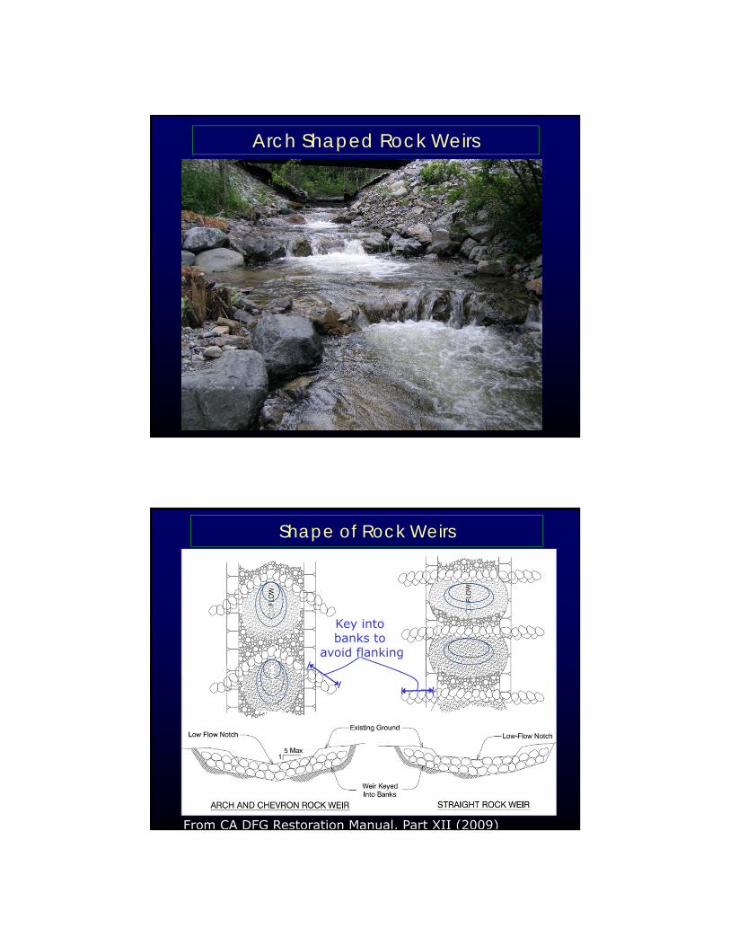
Arch Shaped Rock Weirs
Shape of Rock Weirs
From CA DFG Restoration Manual, Part XII (2009)
Key into banks to
avoid flanking

Footing of Rock Weirs
> Calculated D100
60
Spacing of Rock Weirs
Drop
RockWeir
Pool scoured into native streambed material
~
Design Profile
DropOversteepened
Design Profile
~Small Pools,poor sealing, unstable rock
61
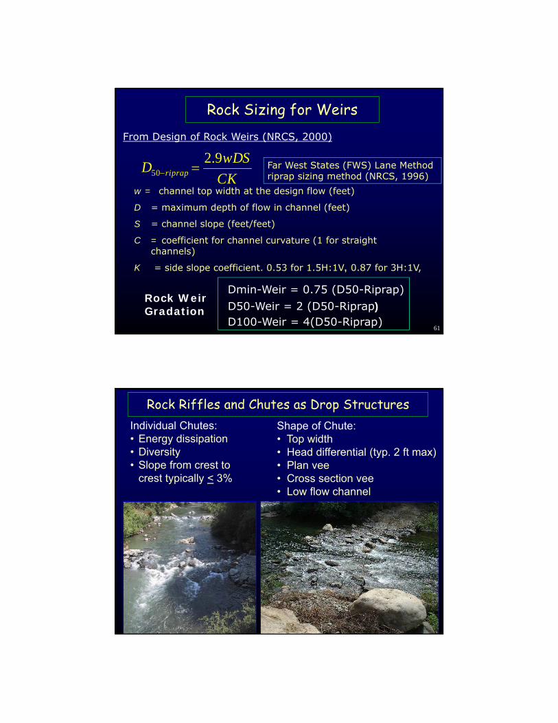
Rock Sizing for Weirs
CK
wDSD riprap
9.250
Far West States (FWS) Lane Method riprap sizing method (NRCS, 1996)
From Design of Rock Weirs (NRCS, 2000)
w = channel top width at the design flow (feet)
D = maximum depth of flow in channel (feet)
S = channel slope (feet/feet)
C = coefficient for channel curvature (1 for straight channels)
K = side slope coefficient. 0.53 for 1.5H:1V, 0.87 for 3H:1V,
D100-Weir = 4(D50-Riprap)D50-Weir = 2 (D50-Riprap) Dmin-Weir = 0.75 (D50-Riprap)
Rock Weir Gradation
62
Individual Chutes:• Energy dissipation• Diversity• Slope from crest to
crest typically < 3%
Shape of Chute:• Top width• Head differential (typ. 2 ft max)• Plan vee• Cross section vee• Low flow channel
Rock Riffles and Chutes as Drop Structures

63
Riffles and Chutes
Spring Prairie CrCobble riffle
From Luther Aadland
64
Rock Riffles and Chutes
65
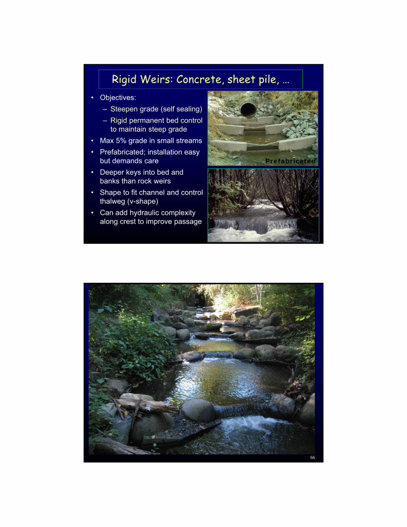
Rigid Weirs: Concrete, sheet pile, …• Objectives:
– Steepen grade (self sealing)
– Rigid permanent bed control to maintain steep grade
• Max 5% grade in small streams
• Prefabricated; installation easy but demands care
• Deeper keys into bed and banks than rock weirs
• Shape to fit channel and control thalweg (v-shape)
• Can add hydraulic complexity along crest to improve passage
Prefabricated
66

67
3 pre-cast panels for channels up to 12 ft
Vary arch orientation at channel bends
Modular Arch Drop Structure
Elevation View
Plan View
Boulders keyed loose against weir crest boulders to form “cascade”
Notch to maintain channel thalweg
Existing Channel cross-section
Approx 1:1
Embedded eyes and pin to tie panels together.
68
Log ControlsUsed to raise incised channel
Passage optimized,Habitat not
Log controls

69
Horizontal Double Log Sills
• Keeps log wetted to increases longevity
• Easy to construct
• Spreads out flow
– Forms wide pools, rather than long
– Anticipate bank erosion when keying
• Wide smooth surface/ low hydraulic complexity
– May not be good for juvenile passage
Log controls
70
2003
Failed after 20 years because no bedload
recruitment.
Wildcat Cr Dam bypass channel
Constructed 1983

71
Structure flanked
Log control remainsstructurally sound
Three keys to stability
1. Double log, spiked2. Ballast
(concrete or rock)3. Tiedown
72
Anticipated Scour Depth ≈ 2.0 to 2.5 X Drop Height
Drop Height
Log controls: Rule of Thumb for Scour
Top Log forward of bottom for nappe to freefall into pool
73
http://www.wa.gov/wdfw/hab/engineer/cm/culvert_manual_final.pdf
74
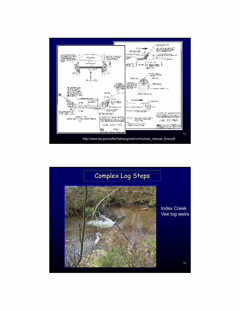
Index CreekVee log weirs
Complex Log Steps

75
Physt R. trib
“X-weirs”
Barnard
Complex Log Steps
76
Dunn Creek
Natural Log Steps
Training logs along bank confine flow

7777
Complex Log Steps
78
Complex Log Steps
No Rock Used

79
Log controls• Straight
– Objective: Steepen grade, optimize select passage, minimize cost and length, secure elevation control
– 5% grade max as bed retention– Uniform channel– Secure designs available
• V- Shape– Objective: Steepen grade, deepen thalweg,
narrow channel, provide select passage– More diverse channel
• Can be made complex• Durable
Tools for Aquatic Organism Passage
Replacement/RemovalRetrofit New
Tech
nica
l Fi
shw
ay
Baffl
es
Na
tura
lBe
d
Rest
ored
Prof
ile
Roug
hene
dC
hann
el
Dro
p St
ruct
ures
Unco
ntro
lled
Regr
adeFish Passage
Approach
Stream CrossingProject
Profile Control
Increasing Ecological Function
Geomorphic ApproachesHydraulic Approaches
80

Fish Passage Resourcesfishxing.orgFishXing Website
• Fish Passage Software• On-Line Presentations • Links to Resources • Case Studies
fishxing.org
Fish Passage Case Studiesfishxing.org