program rf-concrete - dlubaldownload.dlubal.com/?file=manual/en/rf-concrete+members_e.pdf ·...
TRANSCRIPT

Program RF-CONCRETE Members © 2011 Ing.-Software Dlubal
Program
RF-CONCRETE Members Reinforced Concrete Design
Program Description
Version January 2011
All rights, including those of translations, are reserved.
No portion of this book may be reproduced – mechanically, electronically, or by any other means, including photocopy-ing – without written permission of ING.-SOFTWARE DLUBAL. © Ing.-Software Dlubal Am Zellweg 2 D-93464 Tiefenbach
Tel.: +49 (0) 9673 9203-0 Fax: +49 (0) 9673 9203-51 E-mail: [email protected] Web: www.dlubal.com


3Program RF-CONCRETE Members © 2011 Ing.-Software Dlubal
Contents
Contents Page Contents Page
1. Introduction 5 1.1 Add-on module RF-CONCRETE
Members 5 1.2 RF-CONCRETE Members Team 6 1.3 Using the Manual 6 1.4 Open the Add-on Module RF-
CONCRETE Members 7
2. Theoretical Background 9 2.1 Ultimate Limit State Design 9 2.1.1 Bending and Axial Force 9 2.1.2 Shear Force 10 2.2 Serviceability Limit State Design 12 2.2.1 Provided Reinforcement 12 2.2.2 Limitation of Stresses 12 2.2.3 Minimum Reinforcement 13 2.2.4 Limitation of Crack Widths 14 2.2.5 Limitation of Deformations 16 2.2.6 Creep and Shrinkage 17 2.2.6.1 Determination of Initial Values 17 2.2.6.2 Consideration of Creep/Shrinkage by
Calculation 21 2.3 Fire Protection Design 23 2.3.1 Subdivision of Cross-section 23 2.3.2 Reduction of Cross-section 24 2.3.3 Stress-strain Curve of Concrete 26 2.3.4 Stress-strain Curve of Reinforcing Steel 28
3. Input Data 31 3.1 General Data 31 3.1.1 Bearing Capacity 33 3.1.2 Serviceability 34 3.1.3 Details 35 3.1.4 Fire Resistance 36 3.2 Materials 37 3.3 Cross-sections 39 3.4 Ribs 42
3.5 Supports 44 3.6 Reinforcement 46 3.6.1 Longitudinal Reinforcement 47
3.6.2 Links 49 3.6.3 Reinforcement Layout 50 3.6.4 Min Reinforcement 53 3.6.5 Standard 56 3.6.6 Tapered 58 3.6.7 Fire Resistance 60
4. Calculation 62 4.1 Plausibility Check 62 4.2 Start Calculation 62
5. Results 64 5.1 Required Reinforcement 64 5.1.1 Required Reinforcement by Cross-
section 64 5.1.2 Required Reinforcement by Set of
Members 67 5.1.3 Required Reinforcement by Member 67 5.1.4 Required Reinforcement by x-Location 68 5.1.5 Required Reinforcement Not Designable 69 5.2 Provided Reinforcement 70 5.2.1 Longitudinal Reinforcement Provided 70 5.2.2 Shear Reinforcement Provided 74 5.2.3 Reinforcement provided by x-Location 77 5.2.4 Steel Schedule 78 5.3 Serviceability Limit State Design 80 5.3.1 Serviceability Proof by Cross-section 80 5.3.2 Serviceability Proof by Set of Members 83 5.3.3 Serviceability Proof by Member 84 5.3.4 Serviceability Proof by x-Location 84 5.4 Fire Protection Design 85 5.4.1 Fire Protection Design by Cross-section 85 5.4.2 Fire Protection Design by Set of
Members 87 5.4.3 Fire Protection Design by Member 88 5.4.4 Fire Protection Design by x-Location 88 5.4.5 Fire Protection Design Not Designable 89
6. Results Evaluation 90 6.1 Reinforcement Proposal 90 6.2 3D Rendering of Reinforcement 91

4
Contents
Program RF-CONCRETE Members © 2011 Ing.-Software Dlubal
Contents Page Contents Page
6.3 Results in the RFEM Model 93 6.4 Result Diagrams 96 6.5 Filter for Results 97
7. Printout 98 7.1 Printout Report 98 7.2 Graphic Printout 99
8. General Functions 100 8.1 Design Cases in RF-CONCRETE
Members 100
8.2 Cross-section Optimization 102 8.3 Units and Decimal Places 103 8.4 Export of Results 104
9. Example 106
9.1 Input Data 106 9.2 Initial Values of Deformation Analysis 107 9.3 Curvature for Uncracked Sections
(State I) 107 9.4 Curvature for Cracked Sections (State
II) 108 9.5 Determination of Deflection 110
9.6 Result in RF-CONCRETE Members 111
A Literature 112
B Index 114

1 Introduction
5Program RF-CONCRETE Members © 2011 Ing.-Software Dlubal
1. Introduction
1.1 Add-on module RF-CONCRETE Members
The add-on module RF-CONCRETE Members for reinforced concrete design is completely inte-grated in the RFEM user interface. Thus, a continuous analysis process is guaranteed for the de-sign of framework elements consisting of reinforced concrete.
The add-on module imports all relevant structure parameters from RFEM, such as material, cross-sections, members, sets of members, ribs, supports as well as internal forces of defined actions and load combinations. The program allows also for alternative designs with modified cross-sections, including cross-section optimization.
RF-CONCRETE Members analyzes the ultimate and the serviceability limit state. The analysis for cracks and deflections are performed by calculating crack widths and deformations directly. Optionally, the program checks if the requirements of the fire protection design according to EN 1992-1-2:2004 are fulfilled.
The influence of creeping and shrinkage can be taken into account additionally when analyzing the deformed system.
The reinforced concrete design is carried out according to the following national and European standards.
• DIN 1045:1988-07
• DIN 1045-1:2001-07
• DIN 1045-1:2008-08
• DIN V ENV 1992-1-1:1992-06
• ÖNORM B 4700:2001-06
• EN 1992-1-1:2004
• ACI 318-08
The list shown on the left includes the national annexes available for EN 1992-1-1:2004 and is constantly being expanded.
The required reinforcement that is determined contains a reinforcement proposal taking into account all user specifications concerning the rebars in the longitudinal and link reinforcement. This reinforcement layout can always be adjusted. The designs related to the modifications will be updated automatically.
It is possible to visualize the inserted reinforcement by photo-realistic display. This close-to-reality representation of the reinforcement cage can be documented in the global RFEM prin-tout report like all other input and results data of the add-on module.
We hope you will enjoy working with the add-on module RF-CONCRETE Members.
Your team from ING.-SOFTWARE DLUBAL
National annexes for EC 2

1 Introduction
6 Program RF-CONCRETE Members © 2011 Ing.-Software Dlubal
1.2 RF-CONCRETE Members Team The following people were involved in the development of RF-CONCRETE Members:
Program coordination Dipl.-Ing. Georg Dlubal Dipl.-Ing. (FH) Alexander Meierhofer
Dipl.-Ing. (FH) Younes El Frem
Programming Ing. Michal Balvon Jaroslav Bartoš Ing. Ladislav Ivančo Ing. Alexandr Průcha
Ing. Roman Svoboda Dis. Jiří Šmerák RNDr. Stanislav Škovran
Program supervision Dipl.-Ing. (FH) Alexander Meierhofer Ing. Jan Fráňa Ing. Pavel Gruber
Ing. Bohdan Šmid Jana Vlachová
Manual, help system and translation Dipl.-Ing. (FH) Alexander Meierhofer Dipl.-Ing. (FH) Robert Vogl Mgr. Petra Pokorná
Dipl.-Ing. Frank Faulstich Dipl.-Ü. Gundel Pietzcker
Technical support and quality management Dipl.-Ing. (BA) Markus Baumgärtel Dipl.-Ing. (BA) Sandy Baumgärtel Dipl.-Ing. (FH) Steffen Clauß Dipl.-Ing. (FH) Matthias Entenmann Dipl.-Ing. Frank Faulstich Dipl.-Ing. (FH) René Flori Dipl.-Ing. (FH) Stefan Frenzel Dipl.-Ing. (FH) Walter Fröhlich Dipl.-Ing. (FH) Andreas Hörold
Dipl.-Ing. (FH) Bastian Kuhn M.Sc. Dipl.-Ing. Frank Lobisch Dipl.-Ing. (FH) Alexander Meierhofer M.Eng. Dipl.-Ing. (BA) Andreas Niemeier M.Eng. Dipl.-Ing. (FH) Walter Rustler M.Sc. Dipl.-Ing. (FH) Frank Sonntag Dipl.-Ing. (FH) Christian Stautner Dipl.-Ing. (FH) Robert Vogl Dipl.-Ing. (FH) Andreas Wopperer
1.3 Using the Manual Topics like installation, graphical user interface, results evaluation and printout are described in detail in the manual of the main program RFEM. The present manual focuses on typical fea-tures of the add-on module RF-CONCRETE Members.
The descriptions in this manual follow the sequence of the module's input and results tables as well as their structure. The text of the manual shows the described buttons in square brackets, for example [Graphic]. At the same time, they are pictured on the left. In addition, expressions used in dialog boxes, tables and menus are set in italics to clarify the explanations.
At the end of the manual, you find the index. However, if you don’t find what you are looking for, please check our website www.dlubal.com where you can go through our FAQ pages.

1 Introduction
7Program RF-CONCRETE Members © 2011 Ing.-Software Dlubal
1.4 Open the Add-on Module RF-CONCRETE Members
RFEM provides the following options to start the add-on module RF-CONCRETE Members.
Menu To start the program in the menu bar,
point to Design - Concrete on the Additional Modules menu, and then select RF-CONCRETE Members.
Figure 1.1: Menu Additional Modules → Design - Concrete → RF-CONCRETE Members
Navigator To start RF-CONCRETE Members in the Data navigator,
open the Additional Modules folder and select RF-CONCRETE Members.
Figure 1.2: Data navigator: Additional Modules → RF-CONCRETE Members

1 Introduction
8 Program RF-CONCRETE Members © 2011 Ing.-Software Dlubal
Panel In case RF-CONCRETE Members results are already available in the RFEM structure, you can set the relevant design case in the load case list of the RFEM toolbar (see on the left). If necessary, activate the graphical results display first by using the button [Results on/off].
When the results display is activated, the panel appears showing the button [RF-CONCRETE Members] which you can use to access the design module.
Figure 1.3: Panel button [RF-CONCRETE Members]

2 Theoretical Background
9Program RF-CONCRETE Members © 2011 Ing.-Software Dlubal
2. Theoretical Background
2.1 Ultimate Limit State Design In the following, the module's theoretical basis is described in detail. However, this chapter shall not represent a substitute for the contents found in corresponding reference books.
2.1.1 Bending and Axial Force The standards EN 1992-1-1, 6.1 and DIN 1045-1, 10.2 describe in detail the calculation basis for the ultimate limit state design. The corresponding rules refer to bending with or without axial force as well as to axial force only.
The mathematical limit of failure is reached when the ultimate strains are reached. Depending on where the ultimate strains occur, the failure can be caused by the concrete or the reinforc-ing steel.
The following picture shows the allowable strain distributions for bending with and without axial force according to EN 1992-1-1, 6.1.
Figure 2.1: Possible strain distributions in ultimate limit state
According to [16] the different areas for strain distributions shown in the figure above have the following meaning:
Area 1 This area appears in case of a central tension force or a tension force with slight eccentricity. Only strains occur on the entire cross-section. The statically effective cross-section consists only of the two reinforcement layers As1 and As2. The reinforcement fails because the ultimate strain εud is reached.
2 Theoretical Background
10 Program RF-CONCRETE Members © 2011 Ing.-Software Dlubal
Area 2 Area 2 appears in case of bending only and of bending with axial force (compression and ten-sion force). The neutral axis lies within the cross-section. The bending-tension reinforcement is fully used, that means the steel fails when the ultimate strain is reached. Normally, the concrete cross-section is not fully used because the compression strains do not reach the ultimate strain εc2u.
Area 3 This area appears in case of bending only and of bending with axial force (compression). The steel's load-bearing capacity is higher than the capacity of the concrete. The concrete fails be-cause its ultimate strain εc2u is reached.
The concrete's failure is announced by cracks like in the areas 1 and 2 because the steel exceeds the yield point (failure with announcement).
Area 4 Area 4 appears in case of bending with a longitudinal compression force. It represents the tran-sition of a cross-section mainly affected by bending and a cross-section affected by compres-sion. The concrete fails before the steel's yield point is reached because the possible strains are very small. Area 4 implicates a strongly reinforced cross-section. Therefore, to avoid such a cross-section, a compression reinforcement is inserted.
Small steel strains in the tension zone result in failure without announcement (the bending-tension reinforcement does not start to yield).
Area 5 This area appears in case of compression force with a slight eccentricity (for example a column) or of a centric compression force. Only compression strains occur on the entire cross-section. The compression strain on the edge that is less compressed is between 0 > εc1 > εc2. All com-pression strain distributions intersect in point C.
2.1.2 Shear Force The design for shear force resistance is only performed in the ultimate limit state. The actions and resistances are considered with their design values. The general design requirement ac-cording to EN 1992-1-1, 6.2.1 is the following:
VEd ≤ VRd
where VEd Design value of applied shear force
VRd Design value of shear force resistance
Depending on the failure mechanism, the design value of the shear force resistance is deter-mined by one of the following three values:
VRd,c Design shear resistance of a structural component without shear reinforcement
VRd,s Design shear resistance of a structural component with shear reinforcement, limited by yield strength of shear reinforcement (failure of tie)
VRd,max Design shear resistance that is limited by strength of concrete compression strut
If the applied shear force VEd remains below the value of VRd,c, no shear reinforcement is ma-thematically required and the design is fulfilled.
If the applied shear force VEd is higher than the value of VRd,c, a shear reinforcement must de-signed. The shear reinforcement must absorb the entire shear force. In addition, the bearing capacity of the concrete compression strut must be analyzed.
VEd ≤ VRd,s and VEd ≤ VRd,max
2 Theoretical Background
11Program RF-CONCRETE Members © 2011 Ing.-Software Dlubal
The various types of shear force resistance are determined as follows:
Design shear resistance without shear reinforcement The design value for the design shear resistance VRd,c may be determined by:
dbk)f100(kCV wcp131
cklc,Rdc,Rd ⋅⋅⎥⎥
⎦
⎤
⎢⎢
⎣
⎡σ⋅−⋅ρ⋅⋅⋅= EN 1992-1-1, Eq. (6.2a)
where
CRd,c Recommended value: 0.18 / γc
0.2d
2001k ≤+= Scaling factor for considering cross-section depth
d Mean static depth in [mm]
02.0db
A
W
sll ≤
⋅=ρ Ratio of longitudinal reinforcement
Asl Area for tension reinforcement extended by minimum (lbd + d) beyond corresponding cross-section
fck Characteristic value of concrete compressive strength in N/mm2
k1 Recommended value: 0.15
bw Minimum width of cross-section within tension zone in [mm]
d Effective depth of bending reinforcement in [mm]
cdc
Edcp f2.0
AN
⋅<=σ Design value of concrete longitudinal stress in [N/mm2]
You may apply, however, a minimum value of the shear force resistance VRd,c,min.
[ ] dbkvV wcp1minmin,c,Rd ⋅⋅σ⋅+= EN 1992-1-1, Eq. (6.2b)
where
ck3
min f035.0v ⋅κ⋅=
Design shear resistance with shear reinforcement
For structural components with design shear reinforcement perpendicular to the component's axis (α = 90°) the following can be applied:
θ⋅⋅⋅⎟⎠
⎞⎜⎝
⎛= cotfzs
AV ywd
sws,Rd EN 1992-1-1, Eq. (6.8)
where
Asw Cross-sectional area of shear reinforcement
s Distance between links
z Lever arm of internal forces assumed for 0.9 d
fywd Design value for yield strength of shear reinforcement
θ Inclination of concrete compression strut
The inclination of the concrete compression strut θ may be selected within certain limits de-pending on the loading. In this way, the equation can take into account the fact that a part of the shear force is absorbed by crack friction. Thus, the structural system is less stressed. The fol-lowing limits are recommended in equation (6.7) of EN 1992-1-1:
5.2cot1 ≤θ≤
2 Theoretical Background
12 Program RF-CONCRETE Members © 2011 Ing.-Software Dlubal
The inclination of the concrete strut θ can vary between the following values:
Minimum inclination Maximum inclination
θ 21.8° 45.0°
cotθ 2.5 1.0
Table 2.1: Recommended limits for inclination of concrete strut
Design shear resistance of concrete compression strut
For structural components with design shear reinforcement perpendicular to the component's axis (α = 90°) the following can be applied:
θ+θ⋅ν⋅⋅⋅α
=tancot
fzbV cd1wcw
max,Rd EN 1992-1-1, Eq. (6.9)
where
αcw Factor for considering stress conditions in compression chord
bw Width of cross-section
z Lever arm of internal forces (exactly calculated in bending design)
ν1 Reduction factor for concrete strength in case of shear cracks
fcd Design value of concrete strength
θ Inclination of concrete compression strut
2.2 Serviceability Limit State Design The serviceability limit state design consists of various individual designs that are specified in the following Eurocode chapters:
• Limitation of stresses: EN 1992-1-1, 7.2
• Limitation of crack widths: EN 1992-1-1, 7.3
• Limitation of deformations: EN 1992-1-1, 7.4
2.2.1 Provided Reinforcement Before the program designs the serviceability limit state, it checks the provided reinforcement. First, RF-CONCRETE Members uses the internal forces of the serviceability to perform a design similar to the design of the ultimate limit state. The design results in a structurally required reinforcement which is then compared to the user-defined provided reinforcement.
If the provided reinforcement is smaller than the statically required reinforcement, or if the analysis reveals any non-designable situations, the serviceability limit state design won't be per-formed.
2.2.2 Limitation of Stresses
Concrete compressive stresses The concrete compressive stresses must be limited according to EN 1992-1-1, 7.2 (1) in order to avoid cracks or strong creep in case they would affect the structure's functioning. Therefore, chapter 7.2 (2) recommends to apply a reduction factor for the characteristic concrete com-pressive strength.
ck1c fk ⋅=σ
The recommended value for k1 is 0.6.

2 Theoretical Background
13Program RF-CONCRETE Members © 2011 Ing.-Software Dlubal
Reinforcing steel stresses To avoid non-elastic strains, unallowable crack formations and deformations, it is required to limit the tension stresses in the reinforcement according to EN 1992-1-1, 7.2 (4). Chapter 7.2 (5) recommends some reduction factors for the characteristic tensile strength which depend on the type of load combination.
yk3s fk ⋅=σ for characteristic load combination
yk4s fk ⋅=σ for indirect action (restraint)
The recommended values for k3 and k4 are 0.8 and 1.
2.2.3 Minimum Reinforcement The minimum amount of reinforcement used to limit the crack width is determined in accor-dance with EN 1992-1-1, 7.3.2 (2), eq. (7.1) according to the following simplification:
cteff,ctcsmin,s AfkkA ⋅⋅⋅=σ⋅
where
As,min Minimum area of reinforcing steel in tension zone
σs Allowable stress of reinforcement according to Figure 2.2
kc Factor for considering stress distribution in tension zone kc = 1.0 for tension only kc = 0.4 for bending or bending with axial force
k Factor for considering non-linearly distributed self-equilibrating stresses k = 1.0 for webs with h ≤ 300 mm k = 0.65 for h ≥ 800 mm
fct,eff Mean value of the concrete's effective tensile strength when cracks occur fct,eff = fctm
Act Area of concrete within tensile zone
Figure 2.2: Limit diameter Ø*s for reinforcing steels according to EN1992-1-1, table 7.2

2 Theoretical Background
14 Program RF-CONCRETE Members © 2011 Ing.-Software Dlubal
2.2.4 Limitation of Crack Widths
Checking the rebar diameter The limit diameter of the reinforcing bars with max Øs is checked in accordance with EN 1992-1-1, 7.3.3 (2) as follows:
)dh(2hk
9.2
fØØ crceff,ct*ss −⋅
⋅⋅⋅= for bending
)dh(8h
9.2
fØØ creff,ct*ss −⋅
⋅⋅= for uniformly distributed axial tension
where
Øs* Limit diameter according to Figure 2.2
fct,eff Effective tensile strength of concrete at relevant point of time, here fctm
kc Factor for considering stress distribution in tension zone, here kc = 0.4
hcr Depth of tensile zone immediately before cracking occurs
h Total depth of cross-section
d Statically effective depth to centroid of outside reinforcement
Design of rebar spacing The maximum rebar spacing max sl is specified in EN 1992-1-1, table 7.3.
Figure 2.3: Maximum values for rebar spacings according to EN 1992-1-1, table 7.3
Design of crack width The characteristic crack width wk is determined according to EN 1992-1-1, 7.3.4, eq. (7.8).
( )cmsmmax,rk sw ε−ε⋅=
where
sr,max Maximum crack spacing for final crack state according to eq. (7.11) or (7.14)
εsm Mean strain of reinforcement considering contribution of concrete concerning tension between cracks
εcm Mean strain of concrete between cracks

2 Theoretical Background
15Program RF-CONCRETE Members © 2011 Ing.-Software Dlubal
Maximum crack spacing sr,max In case the rebar spacing is not more than 5 · (c + Ø/2) in the tension zone, the maximum crack spacing for the final crack state may be determined according EN 1992-1-1, 7.3.4 (3), eq. (7.11):
eff
4213max,r
Økkkcks
ρ⋅⋅⋅
+⋅=
where
k3 Factor (recommended value: 3.4)
c Concrete cover of longitudinal reinforcement
k1 Factor to consider bond properties k1 = 0.8 for bars with high bond properties k1 = 1.6 for bars with plain surface
k2 Factor to consider distribution of strain k2 = 0.5 for bending k2 = 1.0 for tension only
k4 Factor (recommended value: 0.425)
ρeff Effective reinforcement ratio
If the spacing of rebars lying in the bond exceeds 5 · (c + Ø/2), or if no reinforcement is availa-ble within the bond in the tension zone, the following crack width limit may be assumed:
( )xh3.1s max,r −⋅=
Difference of mean strain (εsm - εcm) The difference of mean strain for concrete and reinforcing steel is determined in accordance with EN 1992-1-1, 7.3.4 (2), eq. (7.9) as follows:
( )
s
s
s
effeeff
eff,ctts
cmsm E6.0
E
1f
kσ
⋅≥ρ⋅α+⋅
ρ⋅−σ
=ε−ε
where
σs Stress in tension reinforcement under assumption of cracked section
kt Factor for creep of bond kt = 0.6 for short-term loading kt = 0.4 for long-term loading
fct,eff Effective tensile strength of concrete at relevant point of time, here fctm
αe Relation of elastic moduli Es / Ecm
ρeff Effective reinforcement ratio

2 Theoretical Background
16 Program RF-CONCRETE Members © 2011 Ing.-Software Dlubal
2.2.5 Limitation of Deformations EN 1992-1-1, 7.4.3 allows for a simplified design to limit deformations by a direct calculation. The deflections must be determined close to reality: The calculation method must express the real structural material performance presenting a certain accuracy that matches with the design purpose.
The deflection is determined from the differential equation of the bending line by double inte-gration. However, as the stiffness of a reinforced concrete cross-section changes in parts due to cracking, the moment-curvature diagram is non-linear. There are big differences in curvature and thus in deflection for uncracked (state I) and cracked sections (state II).
Therefore, the deflection is determined by the principle of virtual work for the location of the maximum deformation. For the curvature an approximate line is applied connecting the ex-treme values of the curvature with a line that is affine with the moment distribution.
When calculating manually, three values of deflection are determined according to [16]:
Lower calculation value of deflection The minimum deflection is achieved when the calculation is performed for a completely un-cracked cross-section (state I). This type of deflection is described as fI.
Upper calculation value of deflection The maximum deflection is achieved when the calculation is performed for a completely cracked cross-section (state II). This type of deflection is described as fII.
Probable value of deflection It is assumed that some parts of the cross-section are uncracked and other, highly-stressed parts are cracked. The moment-curvature relation runs up to the first crack after state I. After state I it shows some cracks. This assumption results in the probable value of deflection f exist-ing between the lower and the upper calculated value. According to EN 1992-1-1, 7.4.3 (3), eq. (7.18) the value can be derived from the following relation:
( ) III 1 α⋅ζ−+α⋅ζ=α
The values αI and αII represent general deflection parameters (for example fI or fII). This can be a strain, curvature, deflection or rotation. ζ is the distribution value between state I and state II and, according to EN 1992-1-1, eq. (7.19), is between 0 ≤ ζ < 1. To determine a probable def-lection, a quasi-permanent combination of action is used for the calculation of internal forces.
Chapter 9 on page 106 shows an example where the manually performed calculation of a de-formation analysis is compared with the RF-CONCRETE Members analysis.

2 Theoretical Background
17Program RF-CONCRETE Members © 2011 Ing.-Software Dlubal
2.2.6 Creep and Shrinkage
2.2.6.1 Determination of Initial Values
This chapter gives an overview about the time-dependent stresses and deformations due to creeping and shrinkage.
Creeping represents the time-dependent deformation of concrete stressed by loading within a specific period of time. The essential influence values are similar to the values of shrinkage. But additionally the so-called creep-producing stress has considerable effects on the creep defor-mation. Special attention must be paid to the load duration, the point of time of load applica-tion as well as to the extent of actions. The creep determining value is represented by the creep ratio ϕ(t,t0) at the relevant point of time t.
Shrinkage describes a time-dependent modification of volume without effects due to external loads or temperature. The present documentation avoids describing further explanations con-cerning shrinkage problems and their individual types of appearance (drying shrinkage, auto-genous shrinkage, plastic shrinkage and carbonation shrinkage). Significant influence values of shrinkage are the relative humidity, the effective thickness of structural components, the ag-gregate, the concrete strength, the water-cement ratio, the temperature as well as the type and duration of curing. The shrinkage determining value is represented by the coefficient of shrinkage εc,s(t,ts) at the relevant point of time t.
The determination of the creep ratio ϕ(t,t0) and the coefficient of shrinkage εc,s(t,ts) according to EN 1992-1-1, annex B, is described in the following.
Creep ratio ϕ(t,t0) Using the following formulas requires that the creep-producing stress σc of the acting perma-nent load does not exceed the following value:
ckjc f45.0 ⋅≤σ
where fckj Compressive cylinder strength of concrete at point of time when creeppro-ducing stress is applied
Figure 2.4: Creep-producing stress
In case a linear creep behavior (σc ≤ 0.45fckj) is assumed, the concrete's creep can be determined by a reduction of the elastic modulus for concrete.
)t,t(1.1E1.1
E0
cmeff,c ϕ+
⋅=
where Ecm Mean elastic modulus according to EN 1992-1-1, table 3.1
ϕ(t,t0) Creep ratio
t Age of concrete in days at relevant point of time
t0 Age of concrete in days when load application starts
2 Theoretical Background
18 Program RF-CONCRETE Members © 2011 Ing.-Software Dlubal
The creep ratio ϕ (t,t0) at the analyzed point of time t may be calculated as follows:
)t,t()t()f()t,t( 0c0cmRH0 β⋅β⋅β⋅ϕ=ϕ
where 2130
RHh1.0
100RH
11 α⋅
⎥⎥⎥⎥
⎦
⎤
⎢⎢⎢⎢
⎣
⎡
α⋅⋅
−+=ϕ
RH Relative humidity in [%]
h0 Effective thickness of structural component [mm]
uA2
h c0
⋅=
Ac Cross-sectional area
u Cross-section perimeter
α1, α2 Coefficients to consider influence of concrete strength 7.0
cm1 f
35⎟⎟⎠
⎞⎜⎜⎝
⎛=α
2.0
cm2 f
35⎟⎟⎠
⎞⎜⎜⎝
⎛=α
fcm Mean value of compressive cylinder strength
cm
cmf
8.16)f( =β
fcm Mean value of compressive cylinder strength of concrete [N/mm2]
20.0
00
t1.0
1)t(
+=β
t0 Age of concrete in days when load application starts
3.0
0H
00c tt
tt)t,t( ⎥
⎦
⎤⎢⎣
⎡
−+β−
=β
t Age of concrete in days at relevant point of time
t0 Age of concrete in days when load application starts
( )[ ] 33018
H 1500250hRH012.015.1 α⋅≤α⋅+⋅⋅+⋅=β
RH Relative humidity [%]
h0 Effective thickness of structural component [mm]
α3 Coefficient to consider influence of concrete strength
13 =α for fcm ≤ 35 N/mm2
5.0
cm3 f
35⎟⎟⎠
⎞⎜⎜⎝
⎛=α for fcm ≥ 35 N/mm2
The following input is required to calculate the creep ratio:
• RH Relative humidity [%]
• t0 Age of concrete in days when load application starts
• t Age of concrete in days at relevant point of time (optionally ∞)
2 Theoretical Background
19Program RF-CONCRETE Members © 2011 Ing.-Software Dlubal
The influence of high or low temperature on the concrete's curing degree in a range of 0 °C to 80 °C can be taken into account by a correction of the age of concrete with the following equa-tion:
∑=
⎥⎦
⎤⎢⎣
⎡−
Δ+−
Δ⋅=n
1ii
65.13)t(T273
4000
T tet i
where n Number of periods with same temperature
T(∆ti) Temperature in °C during period ∆ti
∆ti Number of days with temperature T
The influence of the selected type of cement on the concrete's creep ratio can be taken into ac-count by modifying the concrete's load application age t0 with the following formula:
( ) 5.0t2
91tt
2.1T,0
T,00 ≥⎟⎟
⎠
⎞
⎜⎜
⎝
⎛
++⋅=
α
where t0,T = tT Effective age of concrete when load application starts considering influence of temperature
α Exponent, depends on type of cement
α Type of cement
-1 slow hardening cements of class S
0 normal or rapid hardening cements of class N
1 rapid hardening, high-strength cements of class R
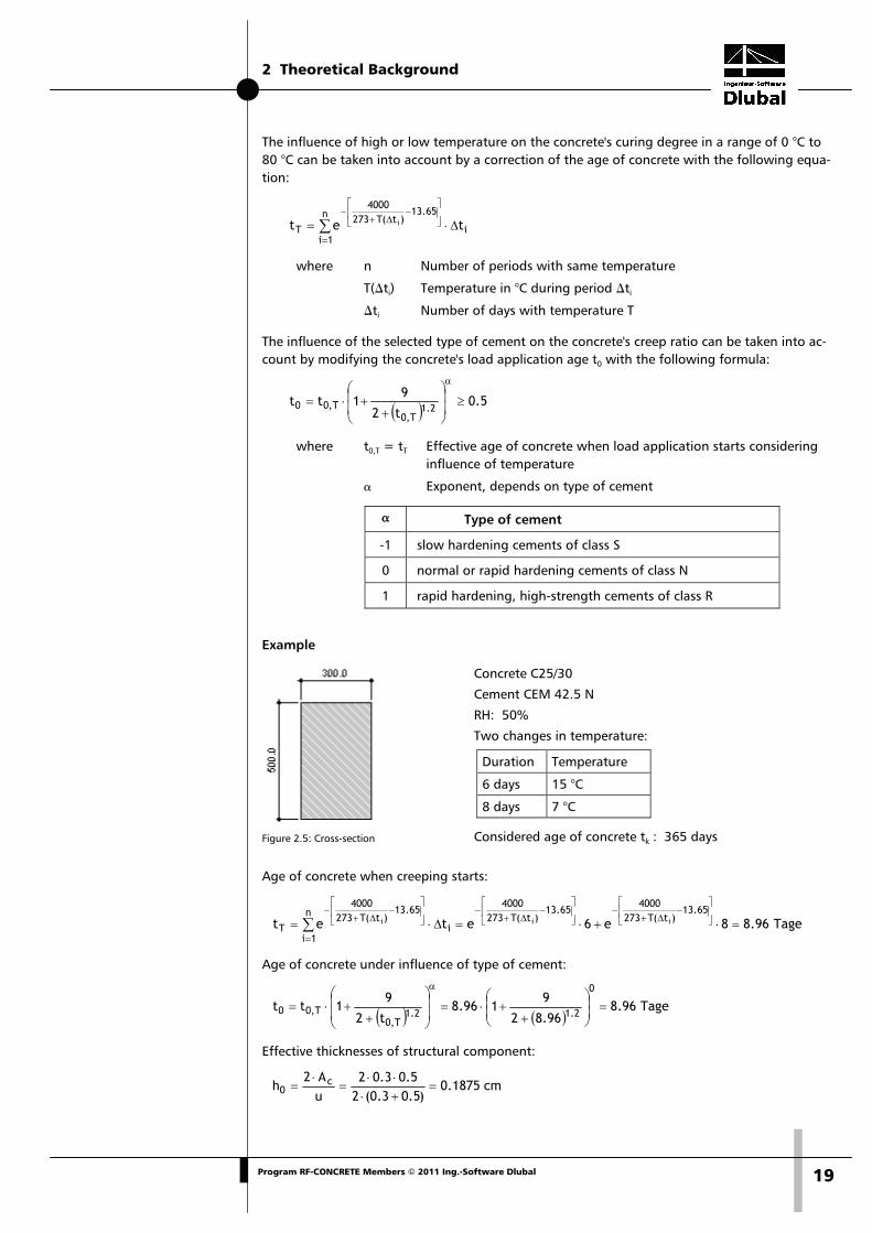
Example
Figure 2.5: Cross-section
Age of concrete when creeping starts:
Tage96.88e6etet65.13
)t(T2734000
65.13)t(T273
4000n
1ii
65.13)t(T273
4000
Tiii =⋅+⋅=Δ⋅=
⎥⎦
⎤⎢⎣
⎡−
Δ+−⎥
⎦
⎤⎢⎣
⎡−
Δ+−
=
⎥⎦
⎤⎢⎣
⎡−
Δ+−
∑
Age of concrete under influence of type of cement:
( ) ( )Tage96.8
96.82
9196.8
t2
91tt
0
2.12.1T,0
T,00 =⎟⎟⎠
⎞⎜⎜⎝
⎛
++⋅=⎟
⎟
⎠
⎞
⎜⎜
⎝
⎛
++⋅=
α
Effective thicknesses of structural component:
cm1875.0)5.03.0(2
5.03.02uA2
h c0 =
+⋅⋅⋅
=⋅
=
Concrete C25/30
Cement CEM 42.5 N
RH: 50%
Two changes in temperature:
Duration Temperature
6 days 15 °C
8 days 7 °C
Considered age of concrete tk : 365 days

2 Theoretical Background
20 Program RF-CONCRETE Members © 2011 Ing.-Software Dlubal
Creep ratio:
595.2758.0606.0923.2933.1)t,t()t()f()t,t( 0c0cmRH0 =⋅⋅⋅=β⋅β⋅β⋅ϕ=ϕ
where
933.1012.1042.15.1871.0
10050
11
h1.0100RH
11
32130
RH =⋅
⎥⎥⎥⎥
⎦
⎤
⎢⎢⎢⎢
⎣
⎡
⋅⋅
−+=α⋅
⎥⎥⎥⎥
⎦
⎤
⎢⎢⎢⎢
⎣
⎡
α⋅⋅
−+=ϕ
042.13335
f35 7.07.0
cm1 =⎟
⎠⎞
⎜⎝⎛=⎟⎟
⎠
⎞⎜⎜⎝
⎛=α 012.1
3335
f35 2.02.0
cm2 =⎟
⎠⎞
⎜⎝⎛=⎟⎟
⎠
⎞⎜⎜⎝
⎛=α
( ) 923.233
8.16
f
8.16f
cmcm ===β
606.096.81.0
1
t1.0
1)t(
2.02.00
0 =+
=+
=β
758.096.8365779.538
96.8365tt
tt)t,t(
3.03.0
0H
00c =⎥⎦
⎤⎢⎣⎡
−+−
=⎥⎦
⎤⎢⎣
⎡
−+β−
=β
( )[ ] ( )[ ] 779.538030.12505.18750012.015.1250hRH012.015.1 1830
18H =⋅+⋅⋅+⋅=α⋅+⋅⋅+⋅=β
1545030.115001500 3H =⋅=α⋅≤β
030.13335 5.0
3 =⎟⎠⎞
⎜⎝⎛=α
Coefficient of shrinkage εc,s(t,ts) The shrinkage can be defined by specifying the shrinkage deformation εc,s(t,ts).
)t,t()f()ts,t( sSRHcmscs β⋅β⋅ε=ε
where ( )[ ] 6cmsccms 10f90160)f( −⋅−⋅β+=ε
Class of cement strength βsc
32.5 4
32.5 R; 42.5 5
42.5 R; 52.5 8
Hardening on air (40 % ≤ RH < 99 %):
sRHRH 55.1 β⋅−=β where 3
sRH 100RH
1 ⎟⎠⎞
⎜⎝⎛−=β
Hardening in water (RH ≥ 99%):
25.0RH =β
s20
ssS
tth035.0
tt)t,t(
−+⋅
−=β
t Age of concrete in days at relevant point of time
ts Age of concrete in days when shrinkage starts

2 Theoretical Background
21Program RF-CONCRETE Members © 2011 Ing.-Software Dlubal
Example
Concrete C25/30
Cement CEM 42.5 R
RH: 50 %
Age of concrete ts when shrinkage starts: 28 days
Considered age of concrete t: 365 days
‰282.0464.0365.1000445.0)t,t()f()ts,t( sSRHcmscs =⋅⋅=β⋅β⋅ε=ε
where
( )[ ] ( )[ ] 000445.0103390516010f90160)f( 66cmsccms =⋅−⋅+=⋅−⋅β+=ε −−
365.1875.055.1RH −=⋅−=β where 875.010050
13
sRH =⎟⎠⎞
⎜⎝⎛−=β
464.0283655.187035.0
28365
tth035.0
tt)t,t(
2s
20
ssS =
−+⋅
−=
−+⋅
−=β
2.2.6.2 Consideration of Creep/Shrinkage by Calculation Creep and shrinkage are considered by calculation as described in the model below:
Creep If the strains are known at the point of time t = 0 as well as any later point of time t, the factor for creeping ϕt can be specified as follows:
10t
tt −
εε
=ϕ=
The equation is converted to the strain at the point of time t. This results in the following con-dition which is valid for uniform stresses (less than approx. 0.4 fck).
( )1t0tt +ϕ⋅ε=ε =
For stresses higher than approx. 0.4 fck the strains are rising disproportionately, resulting in loss of the linearly assumed reference.
For the calculation in RF-CONCRETE Members the program uses a common and reasonable so-lution intended for practical construction purposes: The stress-strain curve of the concrete is distorted by the factor (1+ϕ).
Figure 2.6: Distortion of stress-strain curve for determination of creep effect

2 Theoretical Background
22 Program RF-CONCRETE Members © 2011 Ing.-Software Dlubal
When taking into account creeping, as shown in Figure 2.6, uniform creep-producing stresses are assumed during the period of load application. Due to the neglect of stress redistributions, the deformation is slightly overestimated by this approach. In addition, this model comprises stress reduction only in parts, as change in strains (relaxation) is not taken into account: In case a linear elastic behavior is assumed, it would be possible to imply a proportionality and the ho-rizontal distortion would reflect the relaxation at a ratio of (1+ϕ). This context, however, is lost for the non-linear stress-strain diagram.
Thus, this procedure represents an approximation. A reduction of stresses due to relaxation as well as non-linear creep cannot be or can only be approximately represented.
Shrinkage The question arises how the component's distortions, which are relevant for the calculation, are caused. The reason why they are caused is the concrete's restrained contraction due to the rein-forcement. In case the boundary conditions of common "slender" structural components with uniformly distributed strain due to shrinkage are assumed, component curvatures will only oc-cur for asymmetric distribution of the reinforcement.
Therefore, the shrinkage can be represented by a pre-strain of the concrete or the steel. This means in detail that the "free strain" of the steel is restrained by a positive pre-strain of the con-crete. In the same way, it would be possible to model the component with a negative pre-strain of the steel so that the concrete restrains the free strain of the pre-strained steel. Both models show an identical stress distribution, taking into account the relevant pre-strain, but they differ significantly in the plane of strain: When the steel has been pre-strained, it is imme-diately evident from the strain's condition where zones of tension and compression due to shrinkage occur. When the concrete has been pre-strained, it is possible to make statements from the strain's condition concerning the concrete's actual contraction.
As the determination of deformations is most important for the calculation, it is of no interest whether the modeling, when determining the stiffness, is carried out by a positive pre-strain of the concrete or a negative pre-strain of the reinforcing steel.
The add-on module RF-CONCRETE Members takes into account strain due to shrinkage by neg-ative pre-strain of the reinforcing steel.

2 Theoretical Background
23Program RF-CONCRETE Members © 2011 Ing.-Software Dlubal
2.3 Fire Protection Design The fire protection design with RF-CONCRETE Members is performed according to the simpli-fied calculation method in accordance with EN 1992-1-2, 4.2. The program uses the zone me-thod described in annex B.2.
In case of exposure to fire, the bearing capacity is reduced due to a reduction of the compo-nent's cross-section and a decrease of the material stiffnesses. The damaged concrete zones di-rectly exposed to fire are not taken into account for the equivalent cross-section that is used for the fire protection design. The fire protection design is performed with the reduced cross-section and the reduced material properties similar to the ultimate limit state design at normal temperature.
Figure 2.7: Cross-section exposed to fire with damaged zones
2.3.1 Subdivision of Cross-section The cross-section is subdivided into a certain number of parallel (n > 3) zones having the same thickness. For each zone the program determines the mean temperature, the corresponding compressive strength fc,θ and, if necessary, the modulus of elasticity.
Figure 2.8: Subdivision of a wall with both sides exposed to fire into zones according to [7], figure B.4
The cross-section exposed to fire is compared with a wall. The width of the equivalent wall is 2 * w. The equivalent width is subdivided symmetrically in several zones as shown in Figure 2.8.
Half of the equivalent width w depends on the fire load acting on the structural component. The following table gives an overview about the determination of equivalent widths conform-ing to standards:

2 Theoretical Background
24 Program RF-CONCRETE Members © 2011 Ing.-Software Dlubal
Fire load Half of equivalent width w
Component with one side exposed to fire
Width of component in direction of fire effects
Column or wall with both sides (op-posed) exposed to fire
0.5 * Width of component in direction of fire effects
Column with four sides exposed to fire 0.5 * smallest external cross-section dimension
Table 2.2: Determination of equivalent widths
2.3.2 Reduction of Cross-section
Determination of temperature θi in center of zone Subsequent to the cross-section's subdivision into zones, the temperature θi is determined in the center of each zone i. The determination is facilitated by temperature courses in accordance with EN 1992-1-2, annex A, based on the following assumptions:
• The concrete's specific heat corresponds to the specifications according to EN 1992-1-2, 3.2.2.
• The moisture is 1.5 % (for moistures > 1.5 % the specified temperatures are on the safe side).
• The concrete's thermal conductivity is the lower limit value mentioned in EN 1992-1-2, 3.3.3.
• The emission value for the concrete surface is 0.7.
• The convective heat-transmission coefficient is 25 W/m2K.
Determination of reduction factor kc(θi) The reduction factor kc(θi) is specified for the temperature determined in the center of the zone i in order to take into account the decrease of the characteristic concrete compressive strength fck. The reduction factor kc(θi) depends on the concrete's aggregates.
According to EN 1992-1-2, figure 4.1, graph 1 shown in the diagram below is to be used for normal concrete with aggregates containing quartz. Graph 2 represents normal concrete with aggregates containing limestone.
Figure 2.9: Factor kc(θi) to consider decrease of concrete compressive strength according to [7], figure 4.1

2 Theoretical Background
25Program RF-CONCRETE Members © 2011 Ing.-Software Dlubal
Determination of damaged zone with thickness az The cross-section damaged by fire is represented by a reduced cross-section. This means that a damaged zone of the thickness az on the sides exposed to fire are not taken into account for the ultimate limit state design.
Figure 2.10: Reduction of strength and cross-section in case of fire according to [7], figure B.3
The calculation of the damaged zone thickness az depends on the component type:
• Beams, plates
⎥⎦
⎤⎢⎣
⎡θ
−⋅=)(k
k1wa
Mc
m,cz
• Columns, walls and other structural components for which effects due to second-order analysis must be taken into account
⎥⎥
⎦
⎤
⎢⎢
⎣
⎡
⎟⎟⎠
⎞⎜⎜⎝
⎛
θ−⋅=
3.1
Mc
m,cz )(k
k1wa
where
w Half of width of equivalent wall
kc,m Mean reduction coefficient for a specific cross-section
∑ = θ−
= n1i icm,c )(k
n
)n2.01(
k
n Number of parallel zones in w
The change of temperature in each zone is taken into account by means of the factor (1 – 0.2/n).
kc(θM) Reduction coefficient for concrete at point M (cf. Figure 2.9)

2 Theoretical Background
26 Program RF-CONCRETE Members © 2011 Ing.-Software Dlubal
2.3.3 Stress-strain Curve of Concrete Point M is decisive for the reduction of the concrete's material properties. M is a point on the central line of the equivalent wall (cf. Figure 2.8, page 23). It is used to determine the reduction factor kc(θM). The reduced material properties of the concrete are to be used for the entire re-duced cross-section (without the damaged zone az) in the ultimate limit state design in case of fire.
Concrete compressive strength for fire protection design The stress-strain curve for the concrete compressive strength is determined depending on the temperature in point M as well as on the type of aggregates. Table 3.1 in EN 1992-1-2 contains the values of the compression strain εcu1,θ for the compression strength fc,θ.
ckMc,c f)(kf ⋅θ=θ
where
kc(θM) Reduction coefficient for concrete at point M (see Figure 2.9, page 24)
fck characteristic concrete compressive strength for normal temperature
Figure 2.11: Parameters of stress-strain relation for concrete in case of fire according to [7], table 3.1
Figure 2.12: Stress-strain diagram for concrete with aggregates containing limestone, depending on temperature
2 Theoretical Background
27Program RF-CONCRETE Members © 2011 Ing.-Software Dlubal
As you can see in the diagram (Figure 2.12), the stress-strain relation of normal concrete with aggregates containing limestone is changing depending on the temperature. The decreasing graph is not taken into account for the fire protection design.
The concrete's reduced modulus of elasticity is determined for the fire protection design ac-cording to the following equation:
c2
Mc,cd E)](k[E ⋅θ=θ
where
kc(θM) Reduction coefficient for concrete at point M (see Figure 2.9, page 24)
Ec Elastic modulus of concrete for normal temperature (20 °C)
Tensile strength of concrete for fire protection design In order to be on the safe side, the concrete's tensile strength is not considered for the cross-section design or the fire protection design. For the sake of completeness, however, the values are specified when the material properties are described (c.f. Figure 3.9, page 37).
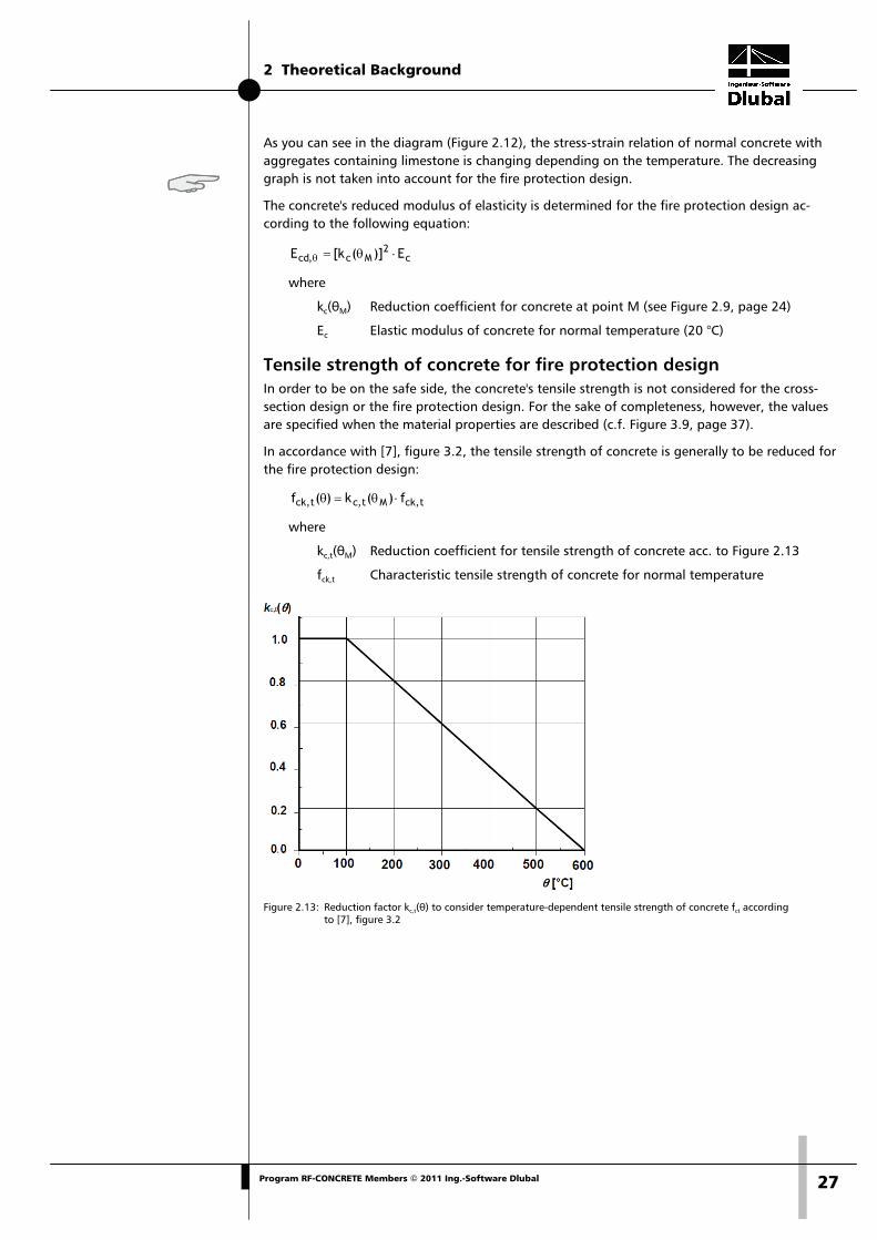
In accordance with [7], figure 3.2, the tensile strength of concrete is generally to be reduced for the fire protection design:
t,ckMt,ct,ck f)(k)(f ⋅θ=θ
where
kc,t(θM) Reduction coefficient for tensile strength of concrete acc. to Figure 2.13
fck,t Characteristic tensile strength of concrete for normal temperature
Figure 2.13: Reduction factor kc,t(θ) to consider temperature-dependent tensile strength of concrete fct according
to [7], figure 3.2

2 Theoretical Background
28 Program RF-CONCRETE Members © 2011 Ing.-Software Dlubal
2.3.4 Stress-strain Curve of Reinforcing Steel
Determination of reduction factor ks(θ) for tensile strength of steel To determine the reduction factor ks(θ), the temperature in the center of the most unfavorable reinforcing member must be determined first. Depending on how the reinforcing steel is pro-duced and classified (class N or X) and how much it is strained, the reduction factor ks(θ) is de-fined.
Class N
Class X
Figure 2.14: Reduction factor ks(θ) to consider temperature-dependent tensile strength of steel according to [7], figure 4.2a/b
Reduction of reinforcing steel strength fsy,θ The stress-strain relation of the reinforcing steel is defined by the following three parameters:
• Slope in linear-elastic zone Es,θ
• Proportionality limit fsp,θ
• Maximum stress level fsy,θ

2 Theoretical Background
29Program RF-CONCRETE Members © 2011 Ing.-Software Dlubal
The maximum strength of the reinforcing steel that is to be applied for the fire protection de-sign is determined as follows:
yks,sy f)(kf ⋅θ=θ
where
ks(θ) Reduction coefficient for reinforcing steel (see Figure 2.14)
fyk characteristic strength of reinforcing steel for normal temperature
Determination of reduced elastic modulus Es,θ of reinforcing steel If the reinforcing steel can be assigned to graph 1 or graph 2 of figure 4.2a or 4.2b shown in EN 1992-1-2 (cf. Figure 2.14), it is possible to take the reinforcing steel's reduced elastic mod-ulus, depending on the steel temperature and type of production, from EN 1992-1-2, table 3.2a or 3.2b.
Class N
Class X
Figure 2.15: Parameters of stress-strain relation for steel in case of fire according to [7], table 3.2a/b

2 Theoretical Background
30 Program RF-CONCRETE Members © 2011 Ing.-Software Dlubal
For reinforcing steels that are assigned to graph 3 according to EN 1992-1-2, figure 4.2a, the reduced modulus of elasticity is calculated as follows:
ss,sy E)(kE ⋅θ=θ
where
ks(θ) Reduction coefficient for reinforcing steel (see Figure 2.14)
Es Elastic modulus of reinforcing steel for normal temperature (20 °C)

3 Input Data
31Program RF-CONCRETE Members © 2011 Ing.-Software Dlubal
3. Input Data All data required for the definition of design cases is entered in tables. The [Pick] function al-lows for a graphical selection of the objects that you want to design.
When you have started the add-on module, a new window opens where a navigator is dis-played on the left, managing all tables that can be selected currently. The pull-down list above the navigator contains the design cases that are already available (see chapter 8.1, page 100).
If you open RF-CONCRETE Members in an RFEM structure for the first time, the module imports the following design relevant data automatically:
• Members and sets of members
• Load cases (LC), load groups (LG) and load combinations (CO)
• Materials
• Cross-sections
• Internal forces (in background, if calculated)
To select a table, click the corresponding entry in the RF-CONCRETE Members navigator or page through the tables by using the buttons shown on the left. You can also use the function keys [F2] and [F3] to select the previous or subsequent table.
To save the defined settings and quit the module, click [OK]. When you click [Cancel], you quit the module but without saving the data.
3.1 General Data In table 1.1 General Data, you select the actions that you want to design. The relevant load cases, groups and combinations can be assigned to the ultimate limit state, the serviceability limit state and the fire protection design by using the respective tab.
Figure 3.1: Table 1.1 General Data, tab Ultimate Limit State

3 Input Data
32 Program RF-CONCRETE Members © 2011 Ing.-Software Dlubal
Concrete Design According to Code / National Annex In this table, the design standard is defined uniformly for all types of design. The following standards for reinforced concrete design can be selected.
Figure 3.2: Selection of design standard
If EN 1992-1-1:2004 is set, you can select the National Annex to the right.
Figure 3.3: Selection of national annex
Use the [Edit] button to check the factors of the selected national annex. If necessary, you can adjust the coefficients.
Figure 3.4: Dialog box Eurocode Settings

3 Input Data
33Program RF-CONCRETE Members © 2011 Ing.-Software Dlubal
In the dialog box Eurocode Settings, click the [New] button to create a copy of the annex cur-rently selected. When you have changed the parameters, you can save the copy using another name. The user-defined parameters are then globally available for all structures in the National Annex list.
Figure 3.5: Creating a user-defined national annex
3.1.1 Bearing Capacity The first tab of table 1.1 General Data is shown in Figure 3.1 on page 31.
Existing Load Cases / Load Groups and Load Combinations These two dialog sections list all actions and load combinations defined in RFEM that are rele-vant for the design. Use the [ ] button to transfer the selected load cases (LC), groups (LG) or combinations (CO) to the list Selected for Design on the right. You can also double-click the items. To transfer the complete list to the right, use the button [ ].
If a load case is marked by an asterisk (*) like load case 9 in Figure 3.1, it is not possible to cal-culate it. This may be the case when no loads are defined or, as you can see in the example, the load case contains only imperfections.
Selected for Design The column on the right lists the loads selected for the design. Use the button [ ] to remove selected load cases, groups or combinations from the list. You can also double-click the items. With the button [ ], you can transfer the entire list to the left.
The analysis of an enveloping Or load combination is often carried out more quickly than the design of all load cases and groups that have been globally set. On the other hand, the influ-ence of the actions contained in a load combination are less transparent for a CO design.
Comment In this input field, you can enter user-defined notes, for example to describe in detail the cur-rent design case.

3 Input Data
34 Program RF-CONCRETE Members © 2011 Ing.-Software Dlubal
3.1.2 Serviceability
Figure 3.6: Table 1.1 General Data, tab Serviceability Limit State
Existing Load Cases / Load Groups and Load Combinations These two dialog sections list all actions and load combinations defined in RFEM. Use the [ ] button to transfer the selected load cases (LC), groups (LG) or combinations (CO) to the list Se-lected for Design on the right. You can also double-click the items. To transfer the complete list to the right, use the button [ ].
Selected for Design The column on the right lists the loads selected for the serviceability limit state design. Use the button [ ] to remove selected load cases, groups or combinations from the list. You can also double-click the items. With the button [ ], you can transfer the entire list to the left.
Activate Creep and Shrinkage When you design the serviceability limit state, you can optionally take into account the influ-ence due to creep and shrinkage. For more information, see chapter 2.2.6 on page 17. If the check box is ticked, you can specify the modulus of creep φ(t,t0) and the shrinkage strain εc,s(t,ts) in table 1.3 Cross-sections (see Figure 3.13, page 41).

3 Input Data
35Program RF-CONCRETE Members © 2011 Ing.-Software Dlubal
3.1.3 Details
Figure 3.7: Table 1.1 General Data, tab Details
If you perform the design according to EN 1992-1-1 or one of the national EN application doc-uments, the Details tab is displayed additionally.
This tab is unnecessary for serviceability limit state designs according to DIN 1045-1 because the factor kt is generally defined with 0.4 in equation (136), section 11.2.4 (2).
LC, LG or CO Description Column A lists all load cases, groups and combinations that have been selected for design in the Serviceability Limit State tab. The load cases that are contained in the selected load groups and combinations are also displayed.
Permanent Load This column indicates the load cases that represent permanent loads. If a load case is specified as permanent load, the factor kt is automatically set to 0.4 in the final column.
Factor kt
The load duration factor kt is used to determine the loading period. The factor is 0.4 for long-term load actions and 0.6 for short-term actions.
For load groups and combinations, the factor kt represents the average of the respective kt val-ues of the load cases contained in the corresponding load group or combination.
( ) ( )
( )∑
∑
=
=
γ
⋅γ=
n
1ii
n
1ii,ti
t
LF
LFkLFk
Equation 3.1

3 Input Data
36 Program RF-CONCRETE Members © 2011 Ing.-Software Dlubal
3.1.4 Fire Resistance
Figure 3.8: Table 1.1 General Data, tab Fire Resistance
Existing Load Cases / Load Groups and Load Combinations These two dialog sections list all actions and load combinations defined in RFEM. Use the [ ] button to transfer the selected load cases (LC), groups (LG) or combinations (CO) to the list Se-lected for Design on the right. You can also double-click the items. To transfer the complete list to the right, use the button [ ].
Selected for Design The column on the right lists the loads selected for the fire protection design. Use the button [ ] to remove selected items from the list. You can also double-click the entries. With the but-ton [ ], you can transfer the entire list to the left.
Reduction Factor The option Reduction Factor acc. to 2.4.2 (2) allows for a simplified transfer of loadings from the design for normal temperature to reduce these actions by the reduction factor ηfi. The re-duction factor is determined as suggested in EN 1992-1-2 according to 2.4.2 (3). As a simplifi-cation you can use the recommended value ηfi = 0.7.

3 Input Data
37Program RF-CONCRETE Members © 2011 Ing.-Software Dlubal
3.2 Materials The table is subdivided into two parts. The upper part lists the concrete and steel grades used for the design. In the Material Properties section below, the properties of the current material, i.e. the table row currently selected in the upper section, are displayed.
Materials that are not used in the design appear gray in color. Materials that are not allowed are highlighted red. Modified materials are displayed in blue.
The material properties required for the determination of internal forces in RFEM are described in detail in chapter 5.3 of the RFEM manual. The design relevant material properties are stored in the global material library and preset automatically.
To adjust the units and decimal places of material properties and stiffnesses, select Units and Decimal Places in the module's Settings menu (see Figure 8.6, page 103).
Figure 3.9: Table 1.2 Materials
Material Description Concrete Strength Class The concrete materials defined in RFEM are already preset. Materials of a different material type are highlighted red. When a manually entered Material Description corresponds to an en-try of the material library, RF-CONCRETE Members will import the appropriate material proper-ties.
It is possible to select another material by using the list: Place the pointer in a table row of col-umn A, and then click the button [ ] or use the function key [F7]. The list shown on the left opens. Subsequent to the transfer, the properties will be updated.
The list contains only materials of the Concrete category complying with the design concept of the selected standard. The import of materials from the library is described below.

3 Input Data
38 Program RF-CONCRETE Members © 2011 Ing.-Software Dlubal
Reinforcing Steel In this column, the program presets a common steel grade that corresponds to the design con-cept of the selected standard.
It is possible to select another reinforcing steel by using the list: Place the pointer in a table row of column B, and then click the button [ ] or use the function key [F7]. The list shown on the left opens. Subsequent to the transfer, the properties will be updated.
The import of materials from the library is described below.
Material Library Numerous concrete and reinforcing steel materials are stored in the library. To open the library, use the button shown on the left. The button can be found below column A and B.
Figure 3.10: Dialog box Material Library
The standard relevant materials are already preset in a preselection so that no other categories or standards are available in the Filter Choice dialog section. Select a material from the list Ma-terial to Select and check the corresponding parameters in the lower part of the dialog box. As a matter of principle, it is not possible to edit the material properties in this dialog box.
Click [OK] or use the [↵] button to import the selected material to table 1.2 of the add-on module.
Chapter 5.3 in the RFEM manual describes in detail how materials can be added or rearranged. By using the [Create New Material] button, you can create new types of concrete or reinforcing steel with user-defined material properties and store them for later use.
3 Input Data
39Program RF-CONCRETE Members © 2011 Ing.-Software Dlubal
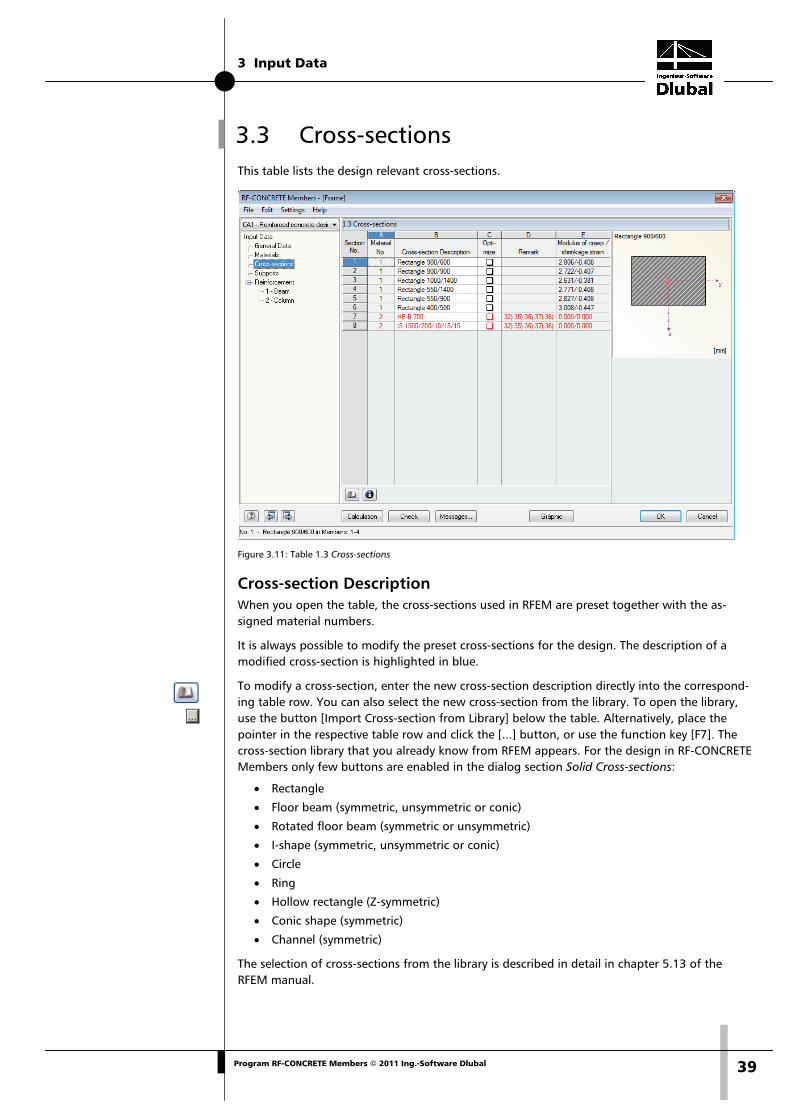
3.3 Cross-sections This table lists the design relevant cross-sections.
Figure 3.11: Table 1.3 Cross-sections
Cross-section Description When you open the table, the cross-sections used in RFEM are preset together with the as-signed material numbers.
It is always possible to modify the preset cross-sections for the design. The description of a modified cross-section is highlighted in blue.
To modify a cross-section, enter the new cross-section description directly into the correspond-ing table row. You can also select the new cross-section from the library. To open the library, use the button [Import Cross-section from Library] below the table. Alternatively, place the pointer in the respective table row and click the [...] button, or use the function key [F7]. The cross-section library that you already know from RFEM appears. For the design in RF-CONCRETE Members only few buttons are enabled in the dialog section Solid Cross-sections:
• Rectangle
• Floor beam (symmetric, unsymmetric or conic)
• Rotated floor beam (symmetric or unsymmetric)
• I-shape (symmetric, unsymmetric or conic)
• Circle
• Ring
• Hollow rectangle (Z-symmetric)
• Conic shape (symmetric)
• Channel (symmetric)
The selection of cross-sections from the library is described in detail in chapter 5.13 of the RFEM manual.

3 Input Data
40 Program RF-CONCRETE Members © 2011 Ing.-Software Dlubal
Figure 3.12: Cross-section Library
If the cross-sections in RF-CONCRETE Members are different from the ones used in RFEM, both cross-sections are displayed in the graphic in the right part of the table.
Optimize For each cross-section it is possible to perform an optimization analysis. By using the internal forces from RFEM the program determines within the same cross-section table the cross-section that meets the reinforcement requirements specified in the dialog box Optimization Pa-rameters with the least possible dimensions (see Figure 8.5, page 102).
To optimize a particular cross-section, tick its check box in column C. Recommendations for op-timizing cross-sections can be found in chapter 8.2 on page 102.
Remark This column shows remarks in the form of footers that are described in detail below the cross-section list.
Modulus of creep / shrinkage strain Column E displays the values for the creep ratio and the strain due to shrinkage determined ac-cording to the preset method. Use the context button shown on the left to adjust the values. A dialog box (see Figure 3.13) opens where you can specify new data.

3 Input Data
41Program RF-CONCRETE Members © 2011 Ing.-Software Dlubal
Figure 3.13: Dialog box Settings for Creep and Shrinkage
The first item Counting Form comprises two possibilities to define the modulus of creep and the coefficient of shrinkage:
• Age Modulus of creep and coefficient of shrinkage are calculated by means of parameters.
• Defined Modulus of creep and coefficient of shrinkage must be specified directly.
How the creep ratio and the shrinkage strain are determined is described in chapter 2.2.6, page 17.
At the end of the table the Result is displayed showing the determined modulus of creep φ(t,t0) and the determined coefficient of shrinkage εc,s(t,ts).
In the dialog section Set Settings for, you can decide whether the entered specifications are applied to a single cross-section, to all cross-sections or to selected cross-sections.

3 Input Data
42 Program RF-CONCRETE Members © 2011 Ing.-Software Dlubal
3.4 Ribs The ribs defined in RFEM are already preset. Ribs represent a special type of member consisting of a beam and a plate cross-section that is also effective (cf. chapter 5.18 of the RFEM manual). The program takes the rib internal forces from RFEM and uses them for the design.
Figure 3.14: Table 1.4 Ribs
The effective widths in this table can be modified either directly by entering values in column D and F or indirectly by using the [Edit Rib] button. A recalculation in RFEM is not required as the system's stiffness is not changed. The calculation of the cross-section properties and the inte-gration of the rib internal forces are always carried out automatically when the effective widths are modified.
Member No. This column shows the numbers of the members that have been defined as member type Rib in RFEM.
Cross-section No. Start / End Column A and B are indicating the cross-section numbers (see chapter 3.3). In case different numbers are displayed, the member is a tapered member.
Effective Widths beff Column D and F show the effective widths for the left and the right side of the member. The values are identical with the specifications entered in the RFEM dialog box New Rib (cf. RFEM manual, figure 5.113 on page 161). Based on the integration widths for the pro rata internal forces in surfaces the rib internal forces are determined.
The effective width is decisive for the cross-section design in the form of an equivalent cross-section. Therefore, you can adjust the values for beff (but increasing the integration width is not allowed). To check the data, tick the check box Show Rib Effective Widths for Determination of Internal Forces: The table will be extended by two further columns and the button [Edit Rib] will be activated (see Figure 3.15).

3 Input Data
43Program RF-CONCRETE Members © 2011 Ing.-Software Dlubal
Figure 3.15: Table 1.4 Ribs
Modifications are shown by dynamic display in the cross-section graphic below the table. The graphic shows the equivalent cross-section that is used for the design.
Reduced effective widths result in reduced member internal forces affecting the design in RF-CONCRETE Members.
Remark In case a rib is a problem for the design, a note is indicated.
The buttons below the table are reserved for the following functions:
Button Description Function
Edit Opens the dialog box Solid Sections - Floor Beam Unsymme-tric including parameters of equivalent cross-section
Edit Rib Opens the dialog box New Rib including rib parameters (cf. RFEM manual, figure 5.113 on page 161)
Info about Cross-section
Shows cross-section properties of equivalent cross-section (type: floor beam unsymmetric)
Table 3.1: Buttons in table 1.4 Ribs
For a correct design of ribs consider the following requirements:
• The rib's local z-axis must be parallel to the local z-axis of the surface.
• The rib's local z-axis must be orthogonal to the xy-axis of the surface plane.
• The connected surface must be defined as surface type Plane.
• The cross-section type of the rib member must be a Rectangle.
• When sets of members are used, a uniform rib type must be defined for the entire set of members.
• The rib member must have the same cross-section at its start and its end. A taper is not allowed.

3 Input Data
44 Program RF-CONCRETE Members © 2011 Ing.-Software Dlubal
3.5 Supports This table provides information about the support conditions of the members that you want to design. The nodal supports defined on horizontal members in RFEM are already preset. If ne-cessary, it is possible to adjust them. RF-CONCRETE Members also recognizes if intermediate or end supports are available.
Non-zero support widths affect the design (redistribution of moments, moment reduction, re-duction of shear force) and the reinforcement proposal (length of anchorage). However, only members in horizontal or slight inclined position are affected, i. e. no columns!
Figure 3.16: Table 1.5 Supports
Node No. This column lists the supported nodes of the members that have a horizontal position or a po-sition that is inclined up to 15°. Use the [...] button to select additional nodes graphically in the RFEM work window.
Support Width b In column B you define the effective width of the corresponding nodal support. In this way you can determine, for example, a wall's wide bearing area which is only represented by a singular support in the RFEM model.
Direct Support The data in this column specifies the support type of the beam. When the load of an adjoining beam is introduced to a main beam, the support is an indirect support and you should clear the check box.
The specifications of this table column affect the lengths of anchorage and the shear design.
Monolithic Connection In column D you decide if a flexurally rigid connection with the column or a free rotary support including reduction options for the supporting moments is available.

3 Input Data
45Program RF-CONCRETE Members © 2011 Ing.-Software Dlubal
End Support An end support has a different influence on the design moment and the lengths of anchorage as an intermediate support. Column E provides a check box for the appropriate assignment.
M-Ratio δ For continuous structural components you can define the ratio δ for the redistributed moment and the elastically determined initial moment in column F. The column is only available if you have ticked the check box Consideration of a restricted moment swap below the graphic on the right.
The δ-values can be determined according to the standard, e.g. EN 1992-1-1, 5.5 (4).
Comment In the final column, you can enter a comment for each support, describing the selected support conditions in detail.
Taking into account the support widths Below the interactive graphic in the table you find three check boxes whose specifications, de-pending on the design standard, have different effects on the required reinforcement. The set-tings are globally valid for the currently selected design case.
Consideration of a restricted moment swap For continuous beams it is possible to apply the linear-elastic methods with limited redistribu-tion of the supporting moments. The resulting distribution of internal forces must be at equili-brium with the acting loads. The standards describe the moment ratios δ that must be ob-served in order to ensure the ability for rotation in the critical areas without special designs, for example EN 1992-1-1, 5.5 (4).
RF-CONCRETE Members determines this limit value and compares it with the value that is speci-fied in column F. The higher value is used for the redistribution.
Reduction of the moments or dimensioning for the moments Optionally, the program performs a moment reduction, for example according to EN 1992-1-1, 5.3.2.2, or DIN 1045-1, 7.3.2, when all of the following requirements are met:
• No end support • Support width > 0 • Support is defined in direction Z • Support force acts positive in Z • Member in horizontal position or with max. inclination of 15° • Negative moment distribution in the entire support zone
The decision whether the moment is reduced or the moment at the face of the support is ap-plied depends on the support's definition in column D: The moment at the face of the support is used for a monolithic connection, for a support with no rotational restraint the supporting moment is reduced.
Reduction of the shear forces in the support area For a direct support it is possible to reduce the design value of the shear force, cf. EN 1992-1-1, 6.2.1 (8) and 6.2.2 (6).
Loads near supports are taken into account, regardless of whether the check box for shear force reduction is ticked, provided that they are designed in the form of load cases or groups.
In case of load combinations the shear force is designed generally on the support's edge be-cause the standard's requirement for a "uniformly distributed load" by means of envelopes is not verifiable in detail.

3 Input Data
46 Program RF-CONCRETE Members © 2011 Ing.-Software Dlubal
3.6 Reinforcement This table consists of several tabs where all reinforcement data is specified. As the individual members often require different reinforcement settings, you can create several reinforcement groups in each design case of RF-CONCRETE Members. The reinforcement specifications can be defined for members as well as for sets of members.
Reinforcement groups To create a new reinforcement group, use the [New] button in the dialog section Reinforce-ment Group. The number is allocated by the program. The user-defined Description helps you to overlook all reinforcement groups created in the design case.
Figure 3.17: Table 1.6 Reinforcement with two reinforcement groups
To select a reinforcement group, use the No. list or the entries in the navigator.
By using the [Delete] button, the currently selected reinforcement group is deleted from the RF-CONCRETE Members case without any additional warning. Members and sets of members that were contained in such a reinforcement group won't be designed. You must reassign them to a new or an existing reinforcement group if you want to design them.
In the dialog section Applied to, you define the members or sets of members to which the cur-rent reinforcement group is applied. All members and All sets of members are preset. If the check boxes are ticked, no further reinforcement group can be created because members and sets of members cannot be designed according to different reinforcement specifications within the same design case. Therefore, in order to use the possibility for several reinforcement groups, clear at least one of the All check boxes.
Enter the numbers of the relevant members or sets of members into the input field. The rein-forcement specifications defined in the tabs of the table will be valid for all selected objects. You can also use the [Pick] button to select the objects graphically in the RFEM work window. Thus, the button [Create New Reinforcement Group] becomes active. For the new group you may only select members and sets of members that are not yet assigned to another reinforce-ment group.

3 Input Data
47Program RF-CONCRETE Members © 2011 Ing.-Software Dlubal
Single members contained in the sets of members will be deactivated automatically for the de-sign.
Reinforcement proposal The graphic in the right part of the table shows how the input in the tabs affect the cross-section. Use the list above the graphic to select another cross-section. The graphic is dynamic: Modifications to the reinforcement specifications are updated and displayed immediately.
If the check box Design the Provided Reinforcement is ticked, RF-CONCRETE Members will use the specifications entered in the various tabs to calculate a rebar reinforcement. If you clear the check box, some of the input fields cannot be accessed. In this case, the program will deter-mine only the required reinforcement areas.
If you activate in table 1.1 General Data the design for the serviceability limit state or for fire protection, it is not possible to clear the check box because it is not active: The SLS design is based on an actually provided reinforcement. Crack widths, crack spacings etc. can be deter-mined only by the applied rebar diameters and spacings. The same applies to a design accord-ing to the non-linear method.
The individual tabs of table 1.6 are described in the following.
3.6.1 Longitudinal Reinforcement In this tab you enter the specifications defining the longitudinal reinforcement.
Figure 3.18: Table 1.6 Reinforcement, tab Longitudinal Reinforcement
Reinforcement In addition to the nominal diameters for rebars mentioned in DIN 488, the list for Possible Di-ameters includes some diameters used outside Germany. A multiple selection is no problem for the design.

3 Input Data
48 Program RF-CONCRETE Members © 2011 Ing.-Software Dlubal
Use the [Edit] button to adjust the list of the displayed rebar diameters.
Figure 3.19: Dialog box Edit List of Possible Diameters
The input line allows for modifying, removing or adding entries.
Reinforcement Layers For the reinforcement proposal RF-CONCRETE Members takes into account also multi-layer ar-rangements of rebars. Use the list to specify the Max. Number of Layers. It is possible to define up to three reinforcement layers. The input fields below allow for entering specifications con-cerning the Minimum Spacing a for rebars of the first layer and b for further layers, if neces-sary.
When the program creates the provided reinforcement, these structural specifications are con-sidered. They affect the number of possible rebars inserted in each layer and the lever arm of internal forces.
If an arrangement of several reinforcement layers is defined, a curtailment of reinforcements is not possible.
Anchorage Type Both lists in this dialog section provide a variety of anchorage possibilities. The graphic to the right is dynamic, this means that modified settings are updated and displayed immediately in the graphic.
The anchorage as well as the Steel Surface (plain, deformed) affect the required length of an-chorage.
Curtailment Type No Curtailment is preset. If you have specified several reinforcement layers, the other two op-tions are disabled.
If you select a Curtailment by Zones, you can use the list to the right to define how many zones with the same reinforcement are allowed in the reinforcement proposal. With this setting RF-CONCRETE Members finds out how to cover the required steel cross-sectional areas with the available rebars in an optimal way.
If Curtailment by Reinforcement Bars is selected, a new zone will be available only when the maximum number of rebars specified is reached. Use the list to the right to define the number of rebars.
Provided Basic Reinforcement In this dialog section, you can specify a basic reinforcement separately for the top and the bot-tom reinforcement layer. When the check boxes are ticked, the input fields below become ac-tive. Enter the number of rebars n and the rebar diameter d to define the reinforcement. The input field As will display the corresponding reinforcement areas.
The user-defined basic reinforcement is taken into account when the reinforcement proposal is created. It will be inserted across the entire length of the member or set of members. If the re-quired reinforcement cannot be covered by the basic reinforcement, RF-CONCRETE will deter-mine the rebars additionally required and insert them into the cross-section.

3 Input Data
49Program RF-CONCRETE Members © 2011 Ing.-Software Dlubal
3.6.2 Links This tab contains reinforcement specifications for the shear reinforcement.
Figure 3.20: Table 1.6 Reinforcement, tab Links
Reinforcement In addition to the nominal diameters for rebars mentioned in DIN 488, the list for Possible Di-ameters includes some diameters used outside Germany. A multiple selection is no problem for the design.
Use the [Edit] button to adjust the list of the displayed rebar diameters (see Figure 3.19).
Link Parameters With the list Number of Links per Section you define the link sections. Two sections are preset. To adjust the presetting, use the list. It is possible to define up to four sections.
The Inclination of the shear reinforcement is defined by the angle between the longitudinal and the shear reinforcement. The program presets 90°, this means that the links are perpendicular. If you want to modify the inclination, observe the standard specifications: EN 1992-1-1, 9.2.2 (1) only allows for angles between 45° and 90°. Furthermore, the code requires in chapter 9.2.2 (4) that bent bars acting as shear reinforcement may be used only together with links. Moreo-ver, it is recommended that at least 50 % of the shear force to be absorbed is covered by links.
Anchorage Type The list provides numerous possibilities for link anchorages affecting the determination of the anchorage length. The graphic to the right is dynamic, this means that modified settings are updated and displayed immediately in the graphic.
Link Layout / Link Spacing This dialog section is only available if you create a reinforcement proposal.
For all members and sets of members a Uniform Spacing Throughout is preset.

3 Input Data
50 Program RF-CONCRETE Members © 2011 Ing.-Software Dlubal
If you select a Zone Related Spacing, you can use the list to the right to define how many zones with the same link layout can be assumed for the reinforcement proposal. In case only one zone is specified, the program creates a further zone in addition to the zone with the maxi-mum link spacing (minimum reinforcement). The additional zone covers the maximum value of the required link reinforcement. When you specify two zones for example, RF-CONCRETE Mem-bers will determine the mean value from the required minimum and maximum reinforcement and applies the corresponding x-locations on the member as further zone limits. The subdivi-sion into further link zones is similar.
If the layout is Subdivided According to Link Spacing, you define a particular spacing for the link zones. The zones change in the corresponding spacing intervals that are determined from the required minimum and maximum reinforcement by an interpolation method.
If you specify a Defined Link Spacing, you can select an entry from the list shown on the left. The [Edit] button allows you to adjust the entries or to create a new entry with user-defined link spacings.
Figure 3.21: Dialog box New List of Allowable Link Distances
The Max. Spacing and the Min. Spacing of the link reinforcement can be defined directly.
The zones determined by the program and shown in the reinforcement proposal can be mod-ified or added subsequently in table 3.2 Shear Reinforcement Provided (see chapter 5.2.2, page 74).
3.6.3 Reinforcement Layout This tab defines how the reinforcement is inserted and which RFEM internal forces will be de-signed.
Figure 3.22: Table 1.6 Reinforcement, tab Reinforcement Layout

3 Input Data
51Program RF-CONCRETE Members © 2011 Ing.-Software Dlubal
Concrete Cover The settings for concrete covers interact with the specification for a reinforcement proposal: If a reinforcement proposal is created, the covers refer to the dimensions of the rebars' edge dis-tance c. But if the program won't calculate a provided reinforcement, the specifications refer to the dimensions of the rebars' centroidal axis u. The following picture shows the difference.
Depending on your specifications, you can access the upper or lower input fields of the dialog section.
Figure 3.23: Relations of concrete cover
In the input field ctop, you enter the concrete cover of the longitudinal reinforcement at the top. In the input field cbottom, you specify the cover of the longitudinal reinforcement at the bottom. These values represent the nominal values cnom of the concrete cover, for example according to EN 1992-11, 4.4.1.1. Based on these specifications and taking into account the ap-plied rebar diameters, RF-CONCRETE Members determines the lever arm of internal forces.
"Top" and "bottom" are clearly defined by the position of the local member axes in RFEM. Speci-fications concerning the cover cside are required to determine the equivalent wall thickness for the torsional design.
For multilayer reinforcements, when entering the cover to the centroidal axis u, you have to take care that the distance refers to the reinforcement's centroid.
Use the check box Cover acc. to Code to set the standard values of the selected design stan-dard. To adjust the values, click the [Edit] button: The settings in the three tabs of the dialog box shown below are decisive for the determination of the values.
Figure 3.24: Dialog box Concrete Cover acc. to Code

3 Input Data
52 Program RF-CONCRETE Members © 2011 Ing.-Software Dlubal
Reinforcement Layout The list contains a variety of possibilities how to lay out the reinforcement in the cross-section:
• Top - Bottom (optimized distribution)
• Top - Bottom (symmetrical distribution)
• Top - Bottom (edit ratio As,top / As)
• Top - Bottom (edit ratio As,tension / As)
• In Corners (symmetrical distribution)
• Uniformly surrounding
For the reinforcement layout Top - Bottom (optimized distribution) RF-CONCRETE Members also performs an optimization for biaxial bending.
Due to this option, it is also possible to define the reinforcement by means of the ratio for top reinforcement and total reinforcement or for tension reinforcement and total reinforcement. The value for the ratio is entered in the input field below the list. In this way, the program faci-litates an efficient replication of existing constructions.
Furthermore, if T-beams and I-sections are used, you can Distribute Reinforcement Evenly over Complete Plate Width. With this option the program releases a part of the rebars.
Modifications to the reinforcement layout are shown by dynamic display in the graphic to the right.
If the moment distribution is My = 0 and Mz > 0 for a Top - Bottom layout, the program's out-put shows increased areas of reinforcement: The design moment is not acting in the distribut-ing direction specified for the reinforcement. In this case, select the In Corners layout in order to perform the design correctly.
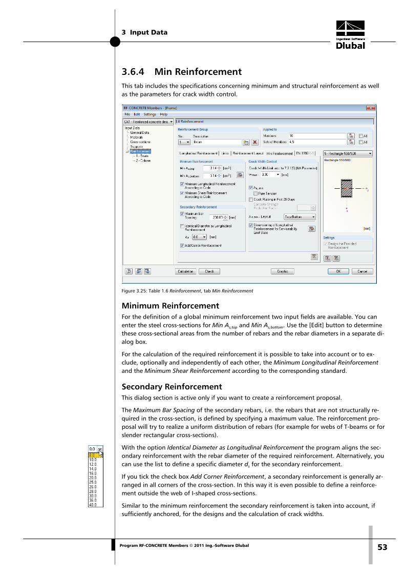
3 Input Data
53Program RF-CONCRETE Members © 2011 Ing.-Software Dlubal
3.6.4 Min Reinforcement This tab includes the specifications concerning minimum and structural reinforcement as well as the parameters for crack width control.
Figure 3.25: Table 1.6 Reinforcement, tab Min Reinforcement
Minimum Reinforcement For the definition of a global minimum reinforcement two input fields are available. You can enter the steel cross-sections for Min As,top and Min As,bottom. Use the [Edit] button to determine these cross-sectional areas from the number of rebars and the rebar diameters in a separate di-alog box.
For the calculation of the required reinforcement it is possible to take into account or to ex-clude, optionally and independently of each other, the Minimum Longitudinal Reinforcement and the Minimum Shear Reinforcement according to the corresponding standard.
Secondary Reinforcement This dialog section is active only if you want to create a reinforcement proposal.
The Maximum Bar Spacing of the secondary rebars, i.e. the rebars that are not structurally re-quired in the cross-section, is defined by specifying a maximum value. The reinforcement pro-posal will try to realize a uniform distribution of rebars (for example for webs of T-beams or for slender rectangular cross-sections).
With the option Identical Diameter as Longitudinal Reinforcement the program aligns the sec-ondary reinforcement with the rebar diameter of the required reinforcement. Alternatively, you can use the list to define a specific diameter ds for the secondary reinforcement.
If you tick the check box Add Corner Reinforcement, a secondary reinforcement is generally ar-ranged in all corners of the cross-section. In this way it is even possible to define a reinforce-ment outside the web of I-shaped cross-sections.
Similar to the minimum reinforcement the secondary reinforcement is taken into account, if sufficiently anchored, for the designs and the calculation of crack widths.

3 Input Data
54 Program RF-CONCRETE Members © 2011 Ing.-Software Dlubal
Crack Width Control The access to the input fields in this dialog section is only available if the serviceability limit state design has been activated in table 1.1 General Data. In addition, the dialog section is ad-justed to the selected standard. The description in the following refers to EN 1992-1-1.
The Crack Width Limit wmax can be selected in the list. Depending on the environmental condi-tions, the specifications mentioned in EN 1992-1-1, 7.3.1 (5) must be applied.
Figure 3.26: Crack widths depending on exposure class (EN 1992-1-1)
When designing the limitation of crack widths, you have to distinguish between load actions and effects due to restraint. Effects due to restraint are reduced considerably by crack forma-tions within the structural component so that a minimum reinforcement As,min with sufficient dimensions results in a distribution of the entire component reduction on several cracks having respectively small crack widths. The crack widths caused by a load action, however, depend on the available steel stress and the reinforcement layout.
Concerning the factor k used to consider non-linearly distributed self-equilibrating stresses, the German national annex (NA) of EN 1992-1-1, 7.3.2 (2) distinguishes tension stresses due to
• restraint caused in the structural component itself (e.g. from drain of hydration heat) • restraint caused outside of the structural component (for example column settlement).
For load stresses RF-CONCRETE Members calculates the crack width directly according to EN 1992-1-1, 7.3.4. For effects due to restraint the program designs the minimum reinforcement according to EN 1992-1-1, 7.3.2 to limit the specified crack width.
If you want to define the effects due to restraint to be Pure Tension, tick the corresponding check box: The definition affects the factor kc for EN 1992-1-1, eq. (7.1), determining the stress distribution in the cross-section before the first crack is formed. In case of pure tension kc = 1.0. For bending or bending with axial force kc is determined according to eq. (7.2) or (7.3). The mean concrete stress σc is determined from the loads because without load it is not possible to calculate the concrete stress. In case of exclusive bending stress, σc is equal to zero in the struc-tural component's axis and thus, according to eq. (7.2), kc = 0.4. In addition to the stress dis-tribution, the factor kc takes into account approximately the increase of the inner lever arm for crack formation.
When you assume Crack Raising in First 28 Days, the effective tensile strength of concrete fct,eff must be reduced according to EN 1992-1-1, 7.3.2 (2). Enter the corresponding Concrete Strength Reduction Factor into the input field to the right. The national annex for Germany re-quires fct,eff = 0.50 · fctm(28d). If it is not possible to determine definitely the point of time within the first 28 days for the cracking's start, it would be appropriate, in accordance with the na-tional annex for Germany, to assume at least a tensile strength of 3 N/mm2 for normal con-crete.
In case of direct restraint, the extent of reduction is affected by the thickness of the structural component because higher self-equilibrating stresses occur when the cross-section dimensions are increased. However, deformations imposed from outside (for example support deforma-tions) do not cause any self-equilibrating stresses. In such a case the reduction factor is 1.0.
Use the selection field As,min - Layout to define the reinforcement layout to which the minimum reinforcement is assigned.

3 Input Data
55Program RF-CONCRETE Members © 2011 Ing.-Software Dlubal
To check and, if necessary, to adjust the Dimensioning of Longitudinal Reinforcement for Servi-ceability Limit State, use the [Edit] button to the right. The following dialog box opens.
Figure 3.27: Dialog box Settings for Layout of Longitudinal Reinforcement
For the serviceability limit state design you can select various criteria for the stress design and the crack width analysis according to which the reinforcement is designed:
Design Normative specifications in EN 1992-1-1
Limitation of concrete stress σc 7.2 (1)
Limitation of steel stress σs 7.2 (4)
Minimum reinforcement with As 7.3.2 (2)
Limit diameter ds Table 7.2 (see Figure 2.2, page 13)
Maximum rebar spacing lim sl Table 7.3 (see Figure 2.3, page 14)
Limitation of crack width wk 7.3.1 (5) and 7.3.4
Table 3.2: Stress designs and crack width analyses
Generally, only one of the criteria, that means lim ds, lim sl or wk, must be fulfilled for the crack width analysis. If you select the option Find economical reinforcement for crack width design, it is possible to check which one of the three criteria can be covered by using the least necessary reinforcement area. The program will add individual rebars to the provided reinforcement until the design is successfully fulfilled. Click the [Info] button to get more information on the rein-forcement's layout.
The criterion of the minimum reinforcement min As must always be fulfilled in case of effects due to restraint.
Furthermore, you can specify a control of deflections for the Deflection Analysis. The program presets a sag of 1/250 of the span length, the value is recommended in EN 1992-1-1, 7.4.1 (4). The input field allows for defining another Limit.
The design criterion of the deformation ul,z considers the displacement in direction of the local member axis z. The sag is related to the undeformed system, this means that the displacements of the start and end nodes are not considered. The reinforcement's layout for the deformation analysis is carried out according to the simplified method in accordance with EN 1992-1-1, 7.4.3.

3 Input Data
56 Program RF-CONCRETE Members © 2011 Ing.-Software Dlubal
3.6.5 Standard The fifth table tab is reserved for the settings of the standard that you have selected in table 1.1 General Data (see Figure 3.2, page 32). This tab contains the standard-specific reinforce-ment specifications. In the following, the specifications for EN 1992-1-1 are described.
In the tab's bottom section the button [Set Default Values] is displayed. Use this button to reset the initial values of the currently set standard.
Figure 3.28: Table 1.6 Reinforcement, tab EN-1992-1-1
Percentages of Reinforcement The entry in this input field defines the general maximum reinforcement ratio for beams. The standard EN 1992-1-1, 9.2.1.1 (3) recommends to use the value of As,max = 0.04 Ac for tension or compression reinforcement and refers to country-specific regulations. The national annex for Germany defines the maximum value of the sum resulting from tension and compression rein-forcement with As,max = 0.08 Ac which must not be exceeded, also in the zones of overlapping joints.
Various If the concrete compression area is no longer able to absorb the compression forces, a com-pression reinforcement is required. This case occurs when the bending moment resulting from the concrete edge's compression strain of -3.50 ‰ and the strain εyd reaching the yield strength of the reinforcing steel is exceeded. For rebars 500 a related neutral axis depth of x/d = 0.617 appears. If the model includes continuous beams, horizontal beams with undisplacea-ble frames and structural components mainly stressed by bending, it is recommended not to use this limiting bending moment to its full capacity in order to ensure a sufficient ability for rotation.
Tick the check box to limit the depth of the compression area according to EN 1992-1-1, 5.6.3 (2). In this case, the maximum ratio is xd / d = 0.45 for concrete up to strength class C50/60 and xd / d = 0.35 for concrete from strength class C55/67.

3 Input Data
57Program RF-CONCRETE Members © 2011 Ing.-Software Dlubal
Shear Reinforcement The two input fields define the allowable zone for the inclination of concrete struts. In case us-er-defined angles are outside the allowed limits mentioned in the standard, an error message appears.
EN 1992-1-1 describes an integrated model for the calculation of the shear force resistance. For structural components with shear reinforcement perpendicular to the component's axis (α = 90°) the following can be applied:
θ⋅⋅⋅= cotfzs
AV ywd
sws,Rd EN 1992-1-1, Eq. (6.8)
Equation 3.2
where
Asw Cross-sectional area of shear reinforcement
s Distance between links
fywd Design value for yield strength of shear reinforcement
z Lever arm of internal forces (assumed for 0.9 d)
θ Inclination of concrete compression strut
The inclination of the concrete compression strut θ may be selected within certain limits de-pending on the loading. In this way, the equation can take into account the fact that a part of the shear force is absorbed by crack friction. Thus, the structural system is less stressed. These limits are recommended in EN 1992-1-1, Eq. (6.7N) as follows:
5.2cot1 ≤θ≤
Equation 3.3
The inclination of the concrete strut θ can vary between the following values:
Minimum inclination Maximum inclination
θ 20.8° 45°
cotθ 2.5 1
Table 3.2: Limits for inclination of concrete strut
The national annex for Germany allows for a flatter inclination of concrete struts with 18.4°.
0.3
V
V1
f4.12.1
cot0.1
Ed
cc,Rd
cd
cd
≤−
σ⋅+
≤θ≤
Equation 3.4
A flatter concrete compression strut results in reduced tension forces within the shear rein-forcement and thus in a reduced area of reinforcement required.
Factors The two input fields in the upper part define the Partial Safety Factor for concrete γc and for reinforcing steel γs which is used for the ultimate limit state design. The values according to EN 1992-1-1, table 2.1N are preset.
Accordingly, the two input fields in the lower part define the two partial safety factors for the serviceability limit state design. The program presets the values of 1.0 which can also be found in the national annex for Germany.

3 Input Data
58 Program RF-CONCRETE Members © 2011 Ing.-Software Dlubal
The Reduction Factor α used to consider long-term effects on the concrete strength can be spe-cified separately for the compressive and the tensile strength. The values recommended in EN 1992-1-1, 3.1.6 are preset in both input fields.
According to the national annex for Germany, the reduction factor of the concrete compressive strength αcc as well as the factor for the tensile strength of the concrete αct must be defined with 0.85. According to EN 1992-1-1, remark for 3.1.7 (3), the value η · fcd must be reduced ad-ditionally by 10% if the width of the compression area decreases towards the compressed edge of the cross-section. If this condition is given, RF-CONCRETE Members will perform the reduc-tion automatically.
3.6.6 Tapered This tab appears only in case a tapered member has been defined in the RFEM model.
Figure 3.29: Table 1.6 Reinforcement, tab Tapered
RF-CONCRETE Members also designs tapered members provided that the same cross-section type is defined for the member start and the member end. Otherwise it is not possible to inter-polate intermediate values and RFEM displays a corresponding error message before the RFEM calculation is started.
Figure 3.30: Error message in case of incompatible tapered cross-sections
Tapered sets of members will be designed only if the entire set of members has a linear cross-sectional profile.

3 Input Data
59Program RF-CONCRETE Members © 2011 Ing.-Software Dlubal
Tapering The following three options can be selected to describe the taper in detail:
• Uniform
• Bottom
• Top
The specification affects the design as well as the arrangement of the longitudinal reinforce-ment.
Figure 3.31: Taper with inclined bottom side

3 Input Data
60 Program RF-CONCRETE Members © 2011 Ing.-Software Dlubal
3.6.7 Fire Resistance The final tab of this table is only available if you have entered data for the fire protection de-sign in table 1.1 General Data (see chapter 3.1.4, page 36). In this tab you can define the fire-specific design settings.
In the tab's bottom section the button [Set Default Values] is displayed. Use this button to reset the initial values. The fire protection design is performed according to the simplified calculation method described in EN 1992-1-2, 4.2 (see chapter 2.3, page 23).
Figure 3.32: Table 1.6 Reinforcement, tab Fire Resistance
Data for Fire Protection Design The following five selection lists control the parameters, affecting the fire protection design significantly:
• Fire resistance class (according to EN 1992-1-2, 1.6.1 (1))
• Number of zones (zone method according to EN 1992-12, annex B.2)
• Type of concrete aggregate (cf. Figure 2.9, page 24 and Figure 2.11, page 26)
• Classification of reinforcement (cf. Figure 2.14, page 28)
• Production type of reinforcing steel (cf. Figure 2.15, page 29)
For more theoretical details on these parameters, see the description in chapter 2.3, page 23.
In this dialog section, you also define the Cross-section Sides Exposed to Fire. If not All Sides are affected by charring, clear the check box. Then the check boxes around the cross-section symbol to the right become active and you can specify the individual sides directly. The direc-tions refer to the local member axes.
In case of asymmetrical effects of fire, the cross-section is stressed by an additional thermal Precamber due to the temperature gradient that must be taken into account for the calculation according to EN 1992-1-2, 2.4.2 (4). This thermal precamber affects the ultimate limit state of structural components like brackets calculated according to the second-order analysis. Internal-ly, the program creates a member load in the form of a precamber of the cross-section and su-perimposes the load with the design loads.

3 Input Data
61Program RF-CONCRETE Members © 2011 Ing.-Software Dlubal
By ticking the check box Design Longitudinal Reinforcement for Fire Resistance, the reinforce-ment proposal will take into account the effects of fire in addition to the bearing capacity.
Material Factors in Case of Fire The two input fields in the upper part define the Partial Safety Factor for concrete γc and for reinforcing steel γs which is used for the fire protection design. The values recommended in EN 1992-1-2, 2.3 (2) are preset.
The Reduction Factor α used to consider long-term effects on the concrete strength in case of fire can be specified separately for the compressive and the tensile strength. The values of 1.0 recommended in EN 1992-1-1, 3.1.6 are preset in both input fields.
With the option Take Thermal Strain of Concrete and Reinforcement Steel into Account, it is possible to consider the difference between the strain of the "hot" reinforcement and the regu-lar thermal strain of the concrete cross-section in the form of a pre-shortening of the rebar: In case of loading due to temperature, thermal longitudinal strains occur in the concrete and in the reinforcing steel varying within the cross-section because of different temperature distribu-tions. The thermal strains cannot arise everywhere freely in the cross-section as they are influ-enced by the adjacent areas. Generally, it may be assumed that the cross-sections remain plane. As the thermal strain of the reinforcement in the cross-section's edge area is restricted, the rein-forcement is pre-shortened. The zone method according to EN 1992-1-2 includes only a calcu-lation of structural components, this means that the thermal additional strains in the centroid are not taken into account by the standard.However, according to HOSSER [20] it is required to take into account those thermal strains for calculations according to the second-order analysis. The concrete's thermal strain is calculated across the entire concrete cross-section using the temperature's average value.
Take the Proof into Account The annex D of EN 1992-1-2 contains a calculation method for the shear and the torsional de-sign of structural components exposed to fire. This method of calculation is implemented in the add-on module RF-CONCRETE Members and can be activated separately.
As this calculation method for the shear and torsional design is not allowed in Germany, both options are not available for the design according to German standards.

4 Calculation
62 Program RF-CONCRETE Members © 2011 Ing.-Software Dlubal
4. Calculation To start the calculation, click the [Calculation] button that is available in all input tables.
4.1 Plausibility Check Before you start the calculation, it is recommended to check the input data. The [Check] button is available in each input table of the module and is used to start the check. If no input error is detected, the following message will be displayed.
Figure 4.1: Plausibility check is ok
4.2 Start Calculation You can start the calculation by clicking the [Calculation] button that is available in each input table of the add-on module RF-CONCRETE Members.
RF-CONCRETE Members searches for the results of the load cases, load groups and load combi-nations that you want to design. If they cannot be found, the RFEM calculation starts to de-termine the design relevant internal forces. In this determination process, the calculation para-meters preset in RFEM are applied.
You can also start the calculation for RF-CONCRETE Members out of the RFEM user interface. All add-on modules are listed in the dialog box To Calculate like load cases or load groups. To open the dialog box in RFEM,
select To Calculate on the Calculate menu.
Figure 4.2: Dialog box To Calculate

4 Calculation
63Program RF-CONCRETE Members © 2011 Ing.-Software Dlubal
If the design cases of RF-CONCRETE Members are missing in the Not Calculated list, tick the check box Show Additional Modules below the list.
To transfer the selected RF-CONCRETE Members cases to the list on the right, use the button [ ]. Start the calculation by using the [Calculate] button.
You can also use the load case list in the RFEM toolbar to calculate a selected RF-CONCRETE Members case directly: Select the relevant design case and click the button [Results on/off].
Figure 4.3: Direct calculation of an RF-CONCRETE Members design case in RFEM
Subsequently, you can observe the calculation process in a separate dialog box.
Figure 4.4: Design with RF-CONCRETE Members

5 Results
64 Program RF-CONCRETE Members © 2011 Ing.-Software Dlubal
5. Results Table 2.1 Required Reinforcement by Cross-section is displayed immediately after the calcula-tion.
The reinforcement areas required for the ultimate limit state design are listed in the results tables 2.1 to 2.4. If the program created a reinforcement proposal, the provided reinforcement including steel schedule is displayed in the results tables 3.1 to 3.4. The results for the servicea-bility limit state design are represented in the results tables 4.1 to 4.4. Tables 5.1 to 5.4 show the results of the fire protection design. Tables 6.1 to 6.4 are reserved for the results deter-mined by a non-linear design.
All tables can be selected directly in the navigator of RF-CONCRETE Members. You can also use the two buttons shown on the left or the function keys [F2] and [F3] to select the previous or subsequent table.
To save the results and quit the add-on module RF-CONCRETE Members, click [OK].
In the following, the different results tables are described in sequence. Evaluating and checking results is described in chapter 6 Results Evaluation, page 90.
5.1 Required Reinforcement 5.1.1 Required Reinforcement by Cross-section
Figure 5.1: Table 2.1 Required Reinforcement by Cross-section
For all designed cross-sections the program displays the maximum required reinforcement areas resulting from the parameters of the reinforcement groups and the internal forces of the governing actions.
The reinforcement areas of the longitudinal and the link reinforcement are listed according to cross-sections. In both parts of the table the program displays the reinforcement types and de-sign details that have been activated in the dialog box Results to Display (Figure 5.2).

5 Results
65Program RF-CONCRETE Members © 2011 Ing.-Software Dlubal
In the lower part of the table the Detailed Results for the entry selected in the table row above are shown. Thus, due to the design details, it is possible to evaluate the results specifically. The output of the intermediate results in the lower part will be updated automatically as soon as another row is selected in the upper part.
Reinforcement The following longitudinal and link reinforcements are preset:
Reinforcement Explanation
As,top Reinforcement area of required top longitudinal reinforcement due to bending with or without axial force or axial force only
As,bottom Reinforcement area of required bottom longitudinal reinforcement due to bending with or without axial force or axial force only
As,T Reinforcement area of required longitudinal torsion reinforcement, if applicable
asw,V link Area of required shear reinforcement for absorption of shear force, referring to standard length of 1 m
asw,T link Area of required link reinforcement for absorption of torsional mo-ment, referring to standard length of 1 m
Table 5.1: Longitudinal and link reinforcements
The bottom reinforcement is defined on the member side in direction of the positive local member axis z. Accordingly, the top reinforcement is defined in direction of the negative z-axis. To display the local member axes, use the Display navigator in the RFEM graphical user in-terface or the context menu of the member.
Click the button [To Display] to open a dialog box where you can specify the reinforcement and intermediate results that you want to display in both parts of the table. The settings also define the types of results appearing in the printout report.
Figure 5.2: Dialog box Results to Display
Top and Bottom layer

5 Results
66 Program RF-CONCRETE Members © 2011 Ing.-Software Dlubal
Member No. For each cross-section and each reinforcement type, the table shows the number of the mem-ber with the maximum reinforcement area.
Location x The column shows the respective x-location for which the program has determined the mem-ber's maximum reinforcement. For the table output, the program uses the following RFEM member locations x:
• Start and end node
• Partition points according to possibly defined member division
• Extreme values of internal forces
LC / LG / CO This column displays the numbers of the load cases, load groups or load combinations that are decisive for the respective design.
Reinforcement Area Column E contains information about the maximum reinforcement areas required for each reinforcement type. They are necessary to fulfill the ultimate limit state design.
The reinforcements' Unit specified in column F can be adjusted. To modify the corresponding settings,
select Units and Decimal Places on the Settings menu.
The dialog box shown in Figure 8.6 on page 103 opens.
Error Message or Note The final column indicates non-designable situations or notes referring to design problems. The numbers are explained in the status bar.
To display all messages of the currently selected design case, use the [Messages] button shown on the left. A dialog box with relevant information appears.
Figure 5.3: Dialog box Error Messages or Notes

5 Results
67Program RF-CONCRETE Members © 2011 Ing.-Software Dlubal
5.1.2 Required Reinforcement by Set of Members
Figure 5.4: Table 2.2 Required Reinforcement by Set of Members
This table presents the maximum reinforcement areas that are required for the individual sets of members. Details on the columns can be found in the previous chapter 5.1.1.
5.1.3 Required Reinforcement by Member
Figure 5.5: Table 2.3 Required Reinforcement by Member
The maximum reinforcement areas are listed according to members. For tapered beams both cross-section descriptions are displayed to the right of the member numbers.
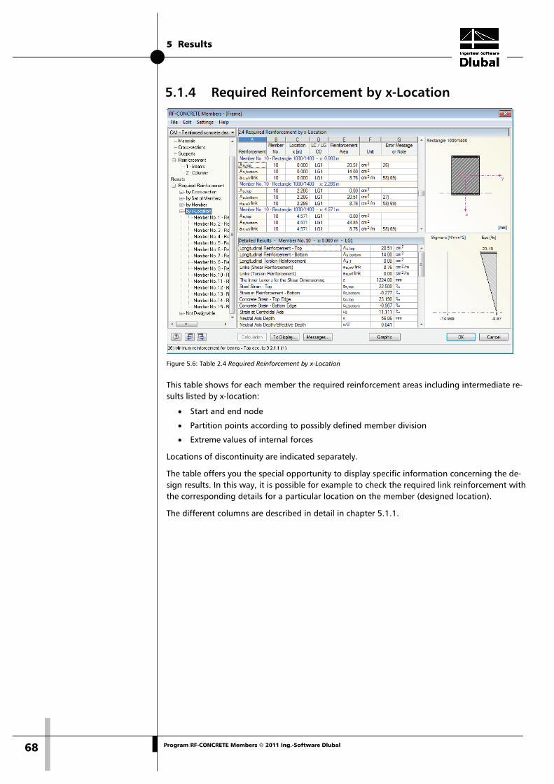
5 Results
68 Program RF-CONCRETE Members © 2011 Ing.-Software Dlubal
5.1.4 Required Reinforcement by x-Location
Figure 5.6: Table 2.4 Required Reinforcement by x-Location
This table shows for each member the required reinforcement areas including intermediate re-sults listed by x-location:
• Start and end node
• Partition points according to possibly defined member division
• Extreme values of internal forces
Locations of discontinuity are indicated separately.
The table offers you the special opportunity to display specific information concerning the de-sign results. In this way, it is possible for example to check the required link reinforcement with the corresponding details for a particular location on the member (designed location).
The different columns are described in detail in chapter 5.1.1.

5 Results
69Program RF-CONCRETE Members © 2011 Ing.-Software Dlubal
5.1.5 Required Reinforcement Not Designable
Figure 5.7: Table 2.5 Required Reinforcement Not Designable
This table is displayed only if the program has detected failed designs or any other problems during the reinforced concrete analysis. The error messages are sorted by members and x-locations.
The number of the Error Message indicated in column G is described by comments in the foo-ter.
Click the [Messages] button to display all specific conditions that have occurred during the de-sign of the current x-location.
Figure 5.8: Dialog box Error Messages or Notes to Design Process
Click the [All] button in this dialog box to show all notes available for RF-CONCRETE Members.

5 Results
70 Program RF-CONCRETE Members © 2011 Ing.-Software Dlubal
5.2 Provided Reinforcement The results tables 3.1 to 3.4 appear only in case the option Design the Provided Reinforcement was activated in table 1.6 Reinforcement (see page 47), and if no design problems were de-tected by the program (see chapter 5.1.5, page 69). Also the serviceability limit state design as well as the non-linear calculation require the determination of a provided reinforcement.
RF-CONCRETE Members determines the reinforcement proposal for the longitudinal and the link reinforcement by using the specifications defined in table 1.6. The program tries to cover the required reinforcement, taking into account the corresponding parameters (specified rebar diameter, possible number of reinforcement layers, curtailment, type of anchorage), by means of the least possible amount of rebars or reinforcement areas.
The proposed reinforcement can be edited in the tables of the Reinforcement Provided so that you can adjust the diameter, number, position and length of the individual reinforcement groups to the respective requirements.
5.2.1 Longitudinal Reinforcement Provided
Figure 5.9: Table 3.1 Longitudinal Reinforcement Provided
The output results for the provided reinforcement are sorted by members and sets of members according to Item numbers (reinforcement groups).
The graphic in the lower table section represents the reinforcement including item members. The currently selected item (the row in the upper table section in which the pointer is placed) is highlighted in red. Modifications to the parameters entered in the upper section are updated and displayed immediately in the graphic.
The reinforcement proposal also takes into account structural regulations. For example, in ac-cordance with EN 1992-1-1, 9.2.1.2, it is required to arrange a minimum reinforcement to sup-ports that are assumed to be pinned, and it must cover at least 25 % of the maximum adjacent moment of span and be available across 25 % of the length of the final span (values for na-tional annex Germany).

5 Results
71Program RF-CONCRETE Members © 2011 Ing.-Software Dlubal
Item No. The results are listed by Items having each the same properties (diameter, length).
The items of all members and sets of members are summarized in table 3.4 Steel Schedule.
Reinforcement Position This table indicates the position of the reinforcement in the cross-section:
• Top
• Bottom
• Corners
• All round
• Secondary
For the reinforcement's arrangement RF-CONCRETE Members takes into account the user speci-fications entered in table 1.6 Reinforcement, tab Reinforcement Layout (see chapter 3.6.3, page 52).
No. of Bars The number of rebars of an item can be edited: Select the corresponding cell and click the but-ton [...] to open the edit dialog box.
Figure 5.10: Dialog box Longitudinal Reinforcement - Coordinates
The Number of Reinforcement Bars can be set manually by using the spin buttons or by enter-ing another number. The numerous input rows in the dialog section below allow you to adjust the position of each rebar. To delete a row selected in the lower section, click the [Delete] but-ton.
The position of a rebar is defined by means of its Bar Coordinates: The coordinates y and z de-termine the global distance from the cross-section's centroid. The angle ( describes the inclina-tion against the longitudinal member axis for the anchorage types "Hook" and "Bend." For ex-ample, a Hook Rotation about the angle β = 90 ° results in a downward rotation (i.e. in direc-tion z) for the top reinforcement. The angle β = 270 ° rotates the anchorage end of the bottom reinforcement upwards. For the anchorage type "Straight", column C is of no importance.
When modifying the hook rotation, it is recommended to check the data subsequently in the rendering mode by clicking the [3D-Rendering] button.

5 Results
72 Program RF-CONCRETE Members © 2011 Ing.-Software Dlubal
ds The used rebar diameters affect the calculation of the inner lever arm of the forces and the number of rebars depending on the position. Use the list to change the rebar diameter for the current item number.
Length This column displays for each item the total length of a representative rebar. The entry, com-posed by the required member length and the lengths of anchorage at both member ends, cannot be edited in this table.
Location x from ... to These values represent the mathematical start and end positions of the rebar. They refer to the member's start node of RFEM (x = 0). When the program determines the dimensions, it takes into account the support conditions and the lengths of anchorage l1 and l2.
The specifications in both columns cannot be modified. To change data, use the [Edit] button in the bottom right corner of the graphic (see Figure 5.12, page 73).
Anchorage The lengths of anchorage of the reinforcement proposal can be changed by using the list. The Details option opens the following edit dialog box.
Figure 5.11: Dialog box Anchorages
This dialog box contains the parameters of the Anchorage on Start and on End of the rebar.
Use the lists to adjust the Anchorage Type and the Bond Type. Please find a description of the anchorage type in chapter 3.6.1 on page 48. RF-CONCRETE Members recognizes automatically the bond conditions resulting from the cross-section geometry and the position of rebars. However, it is also possible to enter user-defined specifications. "Good" and "poor" bond condi-tions are shown in figure 8.2 of EN 1992-1-1, 8.4.2.
For control reasons the program displays the design value of the anchorage length lbd. The lengths l1 of the Anchorage and Additional Lengths is determined by equation (8.4) according to EN 1992-1-1, 8.4.4 (1), taking into account table 8.2, but it cannot be modified.
The length of anchorage l2 for hooks and bends, in accordance with EN 1992-1-1, 8.4.1 (2), should be at least 5 dS.

5 Results
73Program RF-CONCRETE Members © 2011 Ing.-Software Dlubal
The required Bending Diameter dbr is specified according to EN 1992-1-1, table 8.1, and can be adjusted, if necessary.
The total anchorage length Σ at each end of the member is comprised of the respective ratios.
Weight Column I of table 3.1 indicates for each item the mass of all rebars.
Message If a number is displayed in the final column, a special condition is the reason. The footers are explained in the status bar.
To display all messages of the currently selected item, use the [Messages] button shown on the left. A dialog box with relevant information appears (cf. Figure 5.3, page 66).
Change reinforcement proposal The graphic in the lower table section of table 3.1 represents the reinforcement including item members. The currently selected reinforcement position (the row in the upper table section in which the pointer is placed) is highlighted in red. To open the edit dialog box for the selected item, click the [Edit] button in the bottom right corner of the graphic.
Figure 5.12: Dialog box Edit Longitudinal Reinforcement
This dialog box summarizes the reinforcement parameters already described above. Use the di-alog box to control or, if necessary, modify the specifications concerning Location, Bar Position-ing, Reinforcement Diameter and Anchorages.
When you have modified data, the program automatically recalculates the design, using the values of the new provided reinforcement. The results of a non-linear analysis represent an ex-ception: The program deletes these results and a new manual [Calculation] is required.

5 Results
74 Program RF-CONCRETE Members © 2011 Ing.-Software Dlubal
5.2.2 Shear Reinforcement Provided
Figure 5.13: Table 3.2 Shear Reinforcement Provided
Similar to the output for the longitudinal reinforcement, the results for the link reinforcement are sorted by members and sets of members according to Item numbers (reinforcement groups).
The graphic in the lower table section represents the reinforcement including item links. The currently selected item (the row in the upper table section in which the pointer is placed) is highlighted in red. Modifications to the parameters entered in the upper section are updated and displayed immediately in the graphic.
The reinforcement proposal also takes into account structural regulations. For example, in ac-cordance with EN 1992-1-1, 9.2.2 (6), it is recommended to define the maximum spacing for vertical links with sl,max = 0.75d. Table NA 9.1 of the national annex for Germany only allows for reduced longitudinal spacings depending on the shear force ratio and the concrete strength.
Item No. The results are listed by Items having each the same properties (diameter, spacing).
The items of all members and sets of members are summarized in table 3.4 Steel Schedule.
No. of Links When RF-CONCRETE Members determines the link reinforcement, it takes into account the user specifications entered in table 1.6 Reinforcement, tab Links (see chapter 3.6.2, page 49).
The number of links for an item can be edited: Click in the corresponding cell and enter another value. The link spacing (column G) will be adjusted automatically.
ds The reinforcement proposal is based on the specifications defined in table 1.6 Reinforcement, tab Links. Use the list to change the rebar diameter for the current item number.

5 Results
75Program RF-CONCRETE Members © 2011 Ing.-Software Dlubal
Length Column D displays for each item the total length of the link zone. It is determined by the start and end locations x, but cannot be edited in this table. To change data, use the [Edit] button in the bottom right corner of the graphic (see Figure 5.14, page 76).
Location x from ... to These values represent the start and end positions of the link zones. They refer to the member's start node of RFEM (x = 0). The entries in both columns can be edited so that you can shift the zone limits by modifying the values.
To subdivide a zone, enter a location x at the start or end position which lies between both values. RF-CONCRETE Members will automatically create a new link zone.
Spacing sli The proposed link spacing takes into account the specifications defined in table 1.6 Reinforce-ment, tab Link (see chapter 3.6.2, page 49). This value can be edited: Click in the corresponding cell and enter another spacing. The number of links (column B) will be adjusted automatically. The exact link spacing, however, is calculated on the basis of an amount of links defined by an integer.
Link Dimensions In this column, the link dimensions are specified following the sequence "height/width/anchorage length". RF-CONCRETE Members takes into account the defined rebar diameters and concrete covers. The values cannot be edited.
Number of Sections The links' sections are based on the specifications defined in table 1.6 Reinforcement, tab Links (see chapter 3.6.2, page 49). Use the list to change the number of sections.
Weight Column J of table 3.2 indicates for each item the mass of all link rebars.
Message If a number is displayed in the final column, a special condition is the reason. The footers are explained in the status bar.
To display all messages of the currently selected item, use the [Messages] button shown on the left. A dialog box with relevant information appears (cf. Figure 5.3, page 66).

5 Results
76 Program RF-CONCRETE Members © 2011 Ing.-Software Dlubal
Change reinforcement proposal The graphic in the lower table section of table 3.2 represents the reinforcement including item links. The currently selected reinforcement position (the row in the upper table section in which the pointer is placed) is highlighted in red. To open the edit dialog box for the selected item, click the [Edit] button in the bottom right corner of the graphic.
Figure 5.14: Dialog box Edit Shear Reinforcement
This dialog box summarizes the reinforcement parameters already described above. Use the di-alog box to control or, if necessary, modify the specifications concerning Location, Link Dimen-sions and Link Parameters.
When you have modified data, the program automatically recalculates the design, using the values of the new provided link reinforcement. The results of a non-linear analysis represent an exception: The program deletes these results and a new manual [Calculation] is required.

5 Results
77Program RF-CONCRETE Members © 2011 Ing.-Software Dlubal
5.2.3 Reinforcement provided by x-Location This table contains information about the ultimate limit state designs that have been fulfilled or failed. The dynamic of the safety designs represents a great advantage: When modifications are made to the designed reinforcements, the program updates the designs automatically.
Figure 5.15: Table 3.3 Reinforcement provided by x-Location
The upper dialog section lists the longitudinal and link reinforcement areas for each member location x.
Location x The provided reinforcement areas for each member are listed by x-location:
• Start and end node
• Partition points according to possibly defined member division
• Extreme values of internal forces
In case of reinforcements by curtailment, the output shows the x-locations twice for the zone limits.
As,top This value represents the reinforcement area of the provided top longitudinal reinforcement.
As,bottom This value represents the reinforcement area of the provided bottom longitudinal reinforce-ment.
as,link This column shows the area of the provided link reinforcement.
The Detailed Results displayed in the lower dialog section allow for a detailed evaluation of the performed designs. The output includes the design details of the current location x (that means

5 Results
78 Program RF-CONCRETE Members © 2011 Ing.-Software Dlubal
the active location selected in the upper dialog section) including all design-relevant parame-ters.
To reduce the displayed result parameters, use the button [To Display].
Figure 5.16: Dialog box Results to Display
The intermediate results contain information about the Percentage of Reinforcement and the Safety of the selected reinforcement, i.e. the ratio of the provided to the required reinforce-ment. The safety for the longitudinal reinforcement is designed by an increased moment taking into account the global offset.
5.2.4 Steel Schedule The schedule displays the provided rebars combined in a single overview. The table cannot be edited.
Figure 5.17: Table 3.4 Steel Bending Schedule

5 Results
79Program RF-CONCRETE Members © 2011 Ing.-Software Dlubal
Item No. The rebars are listed by Items having each the same properties (diameter, length, type of an-chorage etc.).
Normally, the item numbers are not identical with the numbers of the tables 3.1 and 3.2.
Reinforcement Type This column shows you if the reinforcement is a Longitudinal or a Link reinforcement.
ds Column C indicates the used rebar diameters.
Surface This column displays the surface type of the reinforcing steel which can be Deformed or Plain.
No. of Bars The number of similar rebars of each item is displayed in column E.
Length This column shows for each item the total length of a representative rebar.
Anchorage Type Start / End The two columns provide information about the types of anchorage at the start and the end of the rebars (No anchorage, Straight, Hook, Bend etc.).
Bending Diameter In case links and hooks are used, you find the bending diameter dbr specified in column I.
Weight The final column indicates for each item the mass of all rebars.
Total The final table row of the steel schedule shows the total number of rebars and the mass of steel that is totally required. It is determined from the values of the individual items above.

5 Results
80 Program RF-CONCRETE Members © 2011 Ing.-Software Dlubal
5.3 Serviceability Limit State Design The results tables 4.1 to 4.4 appear only in case the design of the Serviceability Limit State was activated in table 1.1 (see chapter 3.1.2, page 34), and if no design problems were detected by the program (see chapter 5.1.5, page 69 and chapter 5.2.3, page 77).
The design of the serviceability limit state is performed by means of the reinforcement layout that is available as Reinforcement Provided in the tables 3.1 and 3.2.
5.3.1 Serviceability Proof by Cross-section
Figure 5.18: Table 4.1 Serviceability Proof by Cross-section
The table contains the extreme values of different criteria that must be proved for the servicea-bility limit state. The values result from the parameters of the reinforcement groups for the crack width control (see chapter 3.6.4, page 53), the provided reinforcement and the internal forces of the governing actions.
When you evaluate the results of this output table, please consider the descriptions for the di-alog box Settings for Layout of Longitudinal Reinforcement on page 55.
Cross. No. The designs are sorted by cross-section numbers. The final row of the table shows the Govern-ing cross-section for the serviceability limit state design.
Member No. This column displays the number of the member that provides the extreme values for each cross-section type.
Location x The column shows the respective x-location where the most unfavorable values occur. The dis-tances refer to the start node of the governing member.

5 Results
81Program RF-CONCRETE Members © 2011 Ing.-Software Dlubal
LC / LG / CO This column displays the numbers of the load cases, load groups or load combinations that are decisive for the individual designs.
σs The values represent the stresses within the reinforcement in case the tensile zone is cracked. They are determined from the product of the steel strain and the modulus of elasticity:
sss E⋅ε=σ
σc This table column displays the concrete stresses in the serviceability limit state.
min As The minimum area of the rebar reinforcement according to EN 1992-1-1, 7.3.2, eq. (7.1) is:
s
cteff,ctcmin,s
AfkkA
σ⋅⋅⋅=
where kc Factor to take into account the stress distribution within the cross-section before first crack formation
k Factor to take into account self-equilibrating stresses distributed non-linearly across the cross-section
fct,eff Mean value of effective tensile strength of concrete when cracks occur
Act Tension zone of concrete in cracked state in case of first crack formation
fct,eff Effective tensile strength of concrete at decisive point of time
σs Allowable steel stress directly after crack formation (depending on limit di-ameter or maximum value of rebar spacings, where applicable)
lim ds The allowable diameters of the reinforcing steels, in accordance with the simplified design me-thod described in EN 1992-1-1, 7.3.3, are limited to the dimensions mentioned in table 7.2.
Figure 5.19: Limit diameter according to EN 1992-1-1, table 7.2

5 Results
82 Program RF-CONCRETE Members © 2011 Ing.-Software Dlubal
Bar Spacing lim sl The allowable rebar spacings, in accordance with the simplified design method described in EN 1992-1-1, 7.3.3, are limited to the dimensions mentioned in table 7.3.
Figure 5.20: Maximum values for rebar spacings according to EN 1992-1-1, table 7.3
Crack Spacing sr,max This column displays the maximum crack spacing according to EN 1992-1-1, 7.3.4, eq. (7.11) that is available in the final crack state:
eff4213max,r
Økkkcks
ρ⋅⋅⋅+⋅=
where k3 Recommended factor: 3.4 (national annex for Germany: 0)
c Concrete cover of longitudinal reinforcement
k1 Factor to take into account the reinforcement's bond properties: 0.8 for ribbed steel bars or 1.6 for rebars with plain surface
k2 Factor to consider distribution of strain: 0.5 for bending or 1.0 for tension only
k4 Recommended factor: 0.425 (national annex for Germany: 1 / 3.6)
Ø Rebar diameter
ρeff Effective reinforcement ratio according to eq. (7.10): As / Ac,eff
Crack Width max wk The characteristic crack width is determined according to EN 1992-1-1, 7.3.4, eq. (7.8):
( )cmsmmax,rk sw ε−ε⋅=
where sr,max Maximum crack spacing in final crack state
εsm Mean strain of reinforcement considering contribution of concrete concern-ing tension between cracks
εcm Mean strain of concrete between cracks
Deflections ul,z The penultimate column displays respectively the absolute value of the deformation available in direction of the local member axis z.
The settings for the allowable relative deflection are managed in the dialog box Settings for Layout of Longitudinal Reinforcement (see Figure 3.27, page 55).

5 Results
83Program RF-CONCRETE Members © 2011 Ing.-Software Dlubal
Message The final column indicates design problems or shows notes referring to difficulties occurred during the analysis. The footers are explained in the status bar.
To display all messages of the current serviceability limit state design, use the [Messages] but-ton shown on the left. A dialog box with relevant information appears.
Figure 5.21: Dialog box Error Messages or Notes to Design Process
5.3.2 Serviceability Proof by Set of Members
Figure 5.22: Table 4.2 Serviceability Proof by Set of Members
When sets of members have been selected for design, the governing serviceability limit state designs are sorted by sets of members in this results table.
Details on the table columns can be found in the previous chapter 5.3.1.

5 Results
84 Program RF-CONCRETE Members © 2011 Ing.-Software Dlubal
5.3.3 Serviceability Proof by Member
Figure 5.23: Table 4.3 Serviceability Proof by Member
This results table shows the output for the crack width designs sorted by members. The table columns correspond to the columns of table 4.1. They are described in chapter 5.3.1.
5.3.4 Serviceability Proof by x-Location
Figure 5.24: Table 4.4 Serviceability Proof by x-Location
This table lists in detail the various designs (see chapter 5.3.1) according to x-locations.

5 Results
85Program RF-CONCRETE Members © 2011 Ing.-Software Dlubal
5.4 Fire Protection Design The results tables 5.1 to 5.4 appear only in case the design of the Fire Resistance was activated in table 1.1 (see chapter 3.1.4, page 36), and if no design problems were detected by the pro-gram (see chapter 5.1.5, page 69 and chapter 5.2.3, page 77).
The fire protection design is performed by means of the reinforcement layout that is available as Reinforcement Provided in the tables 3.1 and 3.2.
5.4.1 Fire Protection Design by Cross-section
Figure 5.25: Table 5.1 Fire Protection Design by Cross-section
This table shows for each designed cross-section the decisive safety values determined during the fire protection design. The values result from the parameters of the reinforcement groups for the fire designs (see chapter 3.1.4, page 36), the provided reinforcement and the internal forces of the relevant actions.
In the lower part of the table the Detailed Results for the entry selected in the table row above are shown. Thus, due to the design details, it is possible to evaluate the results specifically. The output of the intermediate results in the lower part will be updated automatically as soon as another row is selected in the upper part.
The theoretical background explaining the fire protection design can be found in chapter 2.3, page 23.
Type The safety values are listed according to cross-sections. In addition to the design values for Bending, the table shows the safeties for Shear Force and Torsion, provided that these designs have been specified in the Fire Resistance tab of table 1.6 Reinforcement (see Figure 3.32, page 60).

5 Results
86 Program RF-CONCRETE Members © 2011 Ing.-Software Dlubal
Member No. For each cross-section and each design type, the table shows the number of the member pro-viding the minimum safety.
Location x The column shows the respective x-location on the member which is decisive for the fire pro-tection design. For the table output, the program uses the following RFEM member locations x:
• Start and end node • Partition points according to possibly defined member division • Extreme values of internal forces
LC / LG / CO This column displays the numbers of the load cases, load groups or load combinations that are decisive for the respective designs.
Safety γ Column E informs you about the minimum safety factors γ for each type of design. If the safety is less than 1, the fire protection design has failed and the result row is highlighted in red.
Ratio 1/γ The entries in this column represent the safeties' reciprocal values (column E). In this way, it is possible to evaluate quickly which resources are available until the limit value 1 is reached in the cross-section.
Among the detailed results, you can find all initial values of the designs. The design safeties re-sult from the ratio of the ultimate internal force in case of fire and the analyzed internal force acting on the cross-section.
Figure 5.26: Detailed results, section Design
Error Message or Note The final column indicates non-designable situations or notes referring to design problems. The numbers are explained in the status bar.
To display all messages of the currently selected design case, use the [Messages] button shown on the left. A dialog box with relevant information appears.
Figure 5.27: Dialog box Error Messages or Notes to Design Process

5 Results
87Program RF-CONCRETE Members © 2011 Ing.-Software Dlubal
Temperature course The cross-section used for the fire protection design is graphically displayed to the right of the table. The damaged zone is highlighted in red.
Use the button [Temperature Course] to show the distribution of temperature in the currently selected cross-section. The following dialog box appears:
Figure 5.28: Dialog box Temperature Course
A table displays the Temperature Distribution in Zone Center (cf. chapter 2.3.2, page 24). The graphic shows the Temperature Course in Equivalent Wall according to EN 1992-1-2, annex A.
5.4.2 Fire Protection Design by Set of Members
Figure 5.29: Table 5.2 Fire Protection Design by Set of Members
If sets of members have been selected for design, the fire protection designs are sorted by sets of members in this table. The columns are described in the previous chapter 5.4.1.

5 Results
88 Program RF-CONCRETE Members © 2011 Ing.-Software Dlubal
5.4.3 Fire Protection Design by Member
Figure 5.30: Table 5.3 Fire Protection Design by Member
This table shows the results output of the fire protection designs listed by members. The table columns correspond to the columns of table 5.1. They are described in chapter 5.4.1.
5.4.4 Fire Protection Design by x-Location
Figure 5.31: Table 5.4 Fire Protection Design by x-Location
This results table displays in detail the fire protection designs (cf. chapter 5.4.1) sorted by x-location.
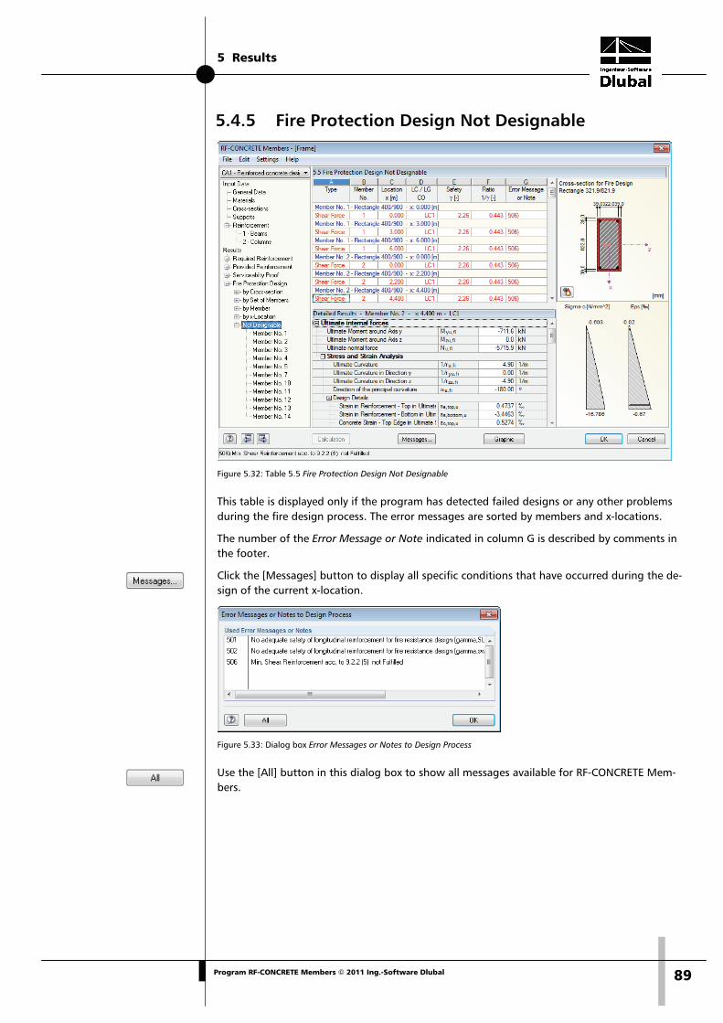
5 Results
89Program RF-CONCRETE Members © 2011 Ing.-Software Dlubal
5.4.5 Fire Protection Design Not Designable
Figure 5.32: Table 5.5 Fire Protection Design Not Designable
This table is displayed only if the program has detected failed designs or any other problems during the fire design process. The error messages are sorted by members and x-locations.
The number of the Error Message or Note indicated in column G is described by comments in the footer.
Click the [Messages] button to display all specific conditions that have occurred during the de-sign of the current x-location.
Figure 5.33: Dialog box Error Messages or Notes to Design Process
Use the [All] button in this dialog box to show all messages available for RF-CONCRETE Mem-bers.

6 Results Evaluation
90 Program RF-CONCRETE Members © 2011 Ing.-Software Dlubal
6. Results Evaluation After the design has been carried out, the results can be evaluated in various ways. The individ-ual results tables are described in detail in chapter 5. This chapter describes the graphical eval-uation.
6.1 Reinforcement Proposal The results tables 3.1 and 3.2 show you how the required areas of reinforcement can be cov-ered with rebars to fulfill the relevant design, for example the serviceability limit state design. The reinforcement proposal is displayed graphically in the form of a drawing in the lower part of table 3.1 Longitudinal Reinforcement Provided and table 3.2 Shear Reinforcement Provided (see Figure 5.9, page 70 and Figure 5.13, page 74).
Figure 6.1: Reinforcement drawing in table 3.1 Longitudinal Reinforcement Provided
The currently selected item (the row in the table above in which the pointer is placed) is hig-hlighted in red. The graphic allows you to display the position and arrangement of the individ-ual item members in order to evaluate them appropriately.
To open the edit dialog box for the selected reinforcement position, click the [Edit] button in the bottom right corner of the drawing. The dialog box is shown in Figure 5.12 on page 73 or in Figure 5.14 on page 76. In this dialog box, you can check the numerous parameters of the selected longitudinal or link reinforcement and, if necessary, adjust them.

6 Results Evaluation
91Program RF-CONCRETE Members © 2011 Ing.-Software Dlubal
6.2 3D Rendering of Reinforcement Both results tables 3.1 Longitudinal Reinforcement and 3.2 Shear Reinforcement provide the button [3D-Rendering] enabling a photo-realistic visualization of the provided reinforcement. A new window opens showing a rendered graphical representation of the reinforcement cage of the current member or set of members (i.e. the table row of the object where the pointer is placed).
Figure 6.2: 3D rendering of provided longitudinal and link reinforcement
By means of the graphic you can check the selected reinforcement close to reality.
To set the graphic display appropriately, use the View pull-down menu or the corresponding buttons (see Table 6.1). Similar to the display in RFEM, you can use the control functions: shift-ing, zooming and rotating the object by keeping the [Shift] or the [Ctrl] key pressed.
The current graphic can also be sent directly to the printer, the printout report or the clipboard.
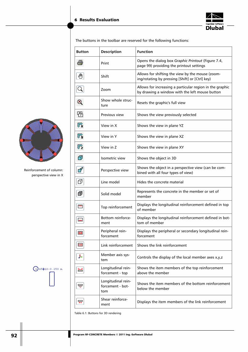
6 Results Evaluation
92 Program RF-CONCRETE Members © 2011 Ing.-Software Dlubal
Reinforcement of column:
perspective view in X
The buttons in the toolbar are reserved for the following functions:
Button Description Function
Print Opens the dialog box Graphic Printout (Figure 7.4, page 99) providing the printout settings
Shift Allows for shifting the view by the mouse (zoom-ing/rotating by pressing [Shift] or [Ctrl] key)
Zoom Allows for increasing a particular region in the graphic by drawing a window with the left mouse button
Show whole struc-ture
Resets the graphic's full view
Previous view Shows the view previously selected
View in X Shows the view in plane YZ
View in Y Shows the view in plane XZ
View in Z Shows the view in plane XY
Isometric view Shows the object in 3D
Perspective view Shows the object in a perspective view (can be com-bined with all four types of view)
Line model Hides the concrete material
Solid model Represents the concrete in the member or set of member
Top reinforcement Displays the longitudinal reinforcement defined in top of member
Bottom reinforce-ment
Displays the longitudinal reinforcement defined in bot-tom of member
Peripheral rein-forcement
Displays the peripheral or secondary longitudinal rein-forcement
Link reinforcement Shows the link reinforcement
Member axis sys-tem
Controls the display of the local member axes x,y,z
Longitudinal rein-forcement - top
Shows the item members of the top reinforcement above the member
Longitudinal rein-forcement - bot-tom
Shows the item members of the bottom reinforcement below the member
Shear reinforce-ment
Displays the item members of the link reinforcement
Table 6.1: Buttons for 3D rendering

6 Results Evaluation
93Program RF-CONCRETE Members © 2011 Ing.-Software Dlubal
6.3 Results in the RFEM Model To evaluate the design results graphically, you can also use the RFEM work window.
RFEM background graphic The RFEM graphic in the background may be useful when you want to check the position of a particular member in the model. When you select a table row in the results table of RF-CONCRETE Members, the corresponding member is highlighted in the RFEM background graphic. In addition, an arrow indicates the member's x-location that is displayed in the cur-rently selected table row.
Figure 6.3: Indication of the member and the current Location x in the RFEM model
This function, however, is only available if the results of the current RF-CONCRETE Members case are set in the RFEM graphical user interface. You can use the [Graphic] button to switch to RFEM and the button [RF-CONCRETE Members] in the control panel to return to the add-on module.

6 Results Evaluation
94 Program RF-CONCRETE Members © 2011 Ing.-Software Dlubal
RFEM work window All reinforcement areas and intermediate results can be visualized on the RFEM structural mod-el: First, click the [Graphic] button to close the add-on module RF-CONCRETE Members. Now, the various reinforcements and design values are displayed in the graphic of the RFEM work window like the internal forces or deformations of a RFEM load case. The display of the differ-ent result types can be set in the Results navigator of RF-CONCRETE Members.
The Results navigator is aligned with the designs of the add-on module RF-CONCRETE Mem-bers. You find all the different reinforcement types for the ultimate and the serviceability limit state design as well as the fire protection design including all intermediate results available for selection.
Figure 6.4: Results navigator of RF-CONCRETE Members and panel with selected result types
The Results navigator allows you to display several reinforcement types or designs at the same time. In this way, it is possible, for example, to compare graphically the required longitudinal reinforcement with the provided longitudinal reinforcement. The panel will be synchronized with the selected types of results.
Due to this multiple selection and the automatic color assignment, the options available in the RFEM Display navigator for the representation of member results are of no relevance.
To turn the display of design results on or off, use the button [Results on/off] shown on the left. To display the result values in the graphic, use the toolbar button [Show Result Values] to the right.
As the RFEM tables are of no relevance for the evaluation of the RF-CONCRETE Members re-sults, you may deactivate them.
The design cases are selected as usual by means of the list in the RFEM menu bar.

6 Results Evaluation
95Program RF-CONCRETE Members © 2011 Ing.-Software Dlubal
As you already know it from the member internal forces, a scaling of member diagrams can be set in the second panel tab Display Factors. This means that you can scale the design results for the evaluation (and the printout) graphically.
Figure 6.5: Panel tab Display Factors
In addition to the required and the provided reinforcement, it is possible to evaluate the inter-mediate results of all designs graphically.
Figure 6.6: Graphical output of required and provided reinforcement as well as fire protection
All results graphics can be transferred like RFEM graphics to the global printout report (see chapter 7.2, page 99).
It is always possible to return to the design module by clicking the button [RF-CONCRETE Members] in the panel.

6 Results Evaluation
96 Program RF-CONCRETE Members © 2011 Ing.-Software Dlubal
6.4 Result Diagrams The result diagrams are available in the RFEM graphic. To display the diagrams,
select Result Diagrams on Selected Members on the Results menu,
or use the button in the RFEM toolbar shown on the left.
A window opens showing the distribution of the reinforcement areas and detailed results on the selected member or set of members.
Figure 6.7: Dialog box Result Diagram on Member
In the navigator to the left, select the reinforcements and detailed results that you want to dis-play in the result diagram. By means of the lists in the toolbar above you can set a particular design case of RF-CONCRETE Members as well as specific members or sets of members for the display.
For more detailed information on the dialog box Result Diagram on Member, see the RFEM manual, chapter 10.5, page 311.

6 Results Evaluation
97Program RF-CONCRETE Members © 2011 Ing.-Software Dlubal
6.5 Filter for Results In addition to the results tables which already allow for a particular selection according to cer-tain criteria because of their structure, you can use the filter options described in the RFEM manual to evaluate the designs graphically.
On the one hand, you can take advantage of already defined partial views (see RFEM manual, chapter 10.9, page 321) used to group objects appropriately.
On the other hand, you can define the numbers of the members, whose results should be shown exclusively in the graphic, in the Filter tab of the control panel. A description of this function can be found in the RFEM manual, chapter 4.4.6, page 77.
Figure 6.8: Filtering members in the panel
In contrast to the partial view function, the model is now displayed completely in the graphic.

7 Printout
98 Program RF-CONCRETE Members © 2011 Ing.-Software Dlubal
7. Printout
7.1 Printout Report The creation of printouts is similar to the printout procedure in RFEM. First, the program gene-rates a printout report for the results of RF-CONCRETE Members. Graphics and descriptions can be added. Moreover, this print preview requires the definition of results which you want to print for the reinforced concrete design.
When your structure is quite extensive, it is advisable to split the data into several small reports. If you create a separate printout report for RF-CONCRETE Members, this printout report will be generated relatively quickly.
The printout report is described in detail in the RFEM manual. In particular, chapter 11.1.3.4 Se-lecting Data of Add-on Modules on page 338 provides information concerning the selection of input and output data in add-on modules.
All general selection options are available in order to print the design cases as well as input and results data of RF-CONCRETE Members.
Figure 7.1: Printout report selection of results of RF-CONCRETE Members, tab Reinforcement

7 Printout
99Program RF-CONCRETE Members © 2011 Ing.-Software Dlubal
7.2 Graphic Printout The design graphics can be either integrated in the printout report or sent directly to the prin-ter. Printing graphics is described in detail in the RFEM manual, chapter 11.2.
Every picture that is displayed in the graphic window of the main program RFEM can be in-cluded into the printout report. Furthermore, it is possible to include the 3D rendering graphics and the member result diagrams in the printout report by using the [Print] button.
To print the current RF-CONCRETE Members graphic displayed in the RFEM work window,
select Print on the File menu
or use the toolbar button shown on the left.
Figure 7.2: Button Print in the toolbar of the main window
Figure 7.3: Button Print in the toolbar of the 3D rendering window
The following dialog box opens:
Figure 7.4: Dialog box Graphic Printout, tab General
This dialog box is described in detail in the RFEM manual, chapter 11.2, page 354. The RFEM manual also describes the Options and Color Spectrum tab.
A graphic from RF-CONCRETE Members, that has been integrated in the printout report, can be moved anywhere within the report by using the drag-and-drop function. In addition, it is poss-ible to adjust inserted graphics subsequently: Right-click the relevant entry in the navigator of the printout report and select Properties in the context menu. The dialog box Graphic Printout opens again, offering different options for modification.

8 General Functions
100 Program RF-CONCRETE Members © 2011 Ing.-Software Dlubal
8. General Functions This chapter describes some menu functions as well as export options for the design results.
8.1 Design Cases in RF-CONCRETE Members Members and sets of members can be arranged in groups for different design cases. In this way, you can define particular design specifications (materials, cross-sections, reinforcement layout etc.) for example for groups of structural components.
It is no problem to analyze the same member or set of member in different design cases.
The design cases of RF-CONCRETE Members are available in the RFEM work window and can be displayed like a load case or load group by means of the toolbar list.
Create a new RF-CONCRETE Members case To create a new design case,
select New Case on the File menu in the RF-CONCRETE Members add-on module.
The following dialog box appears.
Figure 8.1: Dialog box New RF-CONCRETE Members-Case
In this dialog box, enter a No. (which is not yet assigned) and a Description for the new design case. When you click [OK], table 1.1 General Data opens where you can enter the new design data.
Rename a RF-CONCRETE Members case To change the description of a design case subsequently,
select Rename Case on the File menu in the RF-CONCRETE Members add-on module.
The dialog box Rename RF-CONCRETE Members-Case appears.
Figure 8.2: Dialog box Rename RF-CONCRETE Members-Case
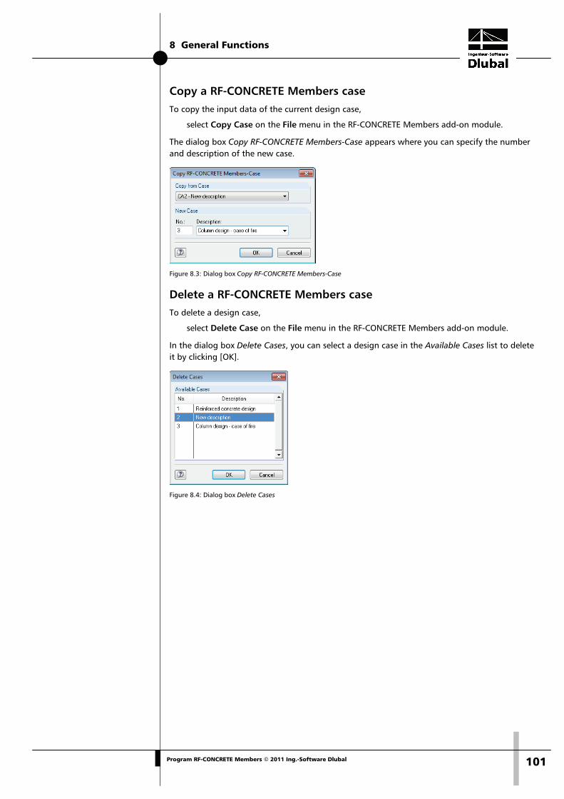
8 General Functions
101Program RF-CONCRETE Members © 2011 Ing.-Software Dlubal
Copy a RF-CONCRETE Members case To copy the input data of the current design case,
select Copy Case on the File menu in the RF-CONCRETE Members add-on module.
The dialog box Copy RF-CONCRETE Members-Case appears where you can specify the number and description of the new case.
Figure 8.3: Dialog box Copy RF-CONCRETE Members-Case
Delete a RF-CONCRETE Members case To delete a design case,
select Delete Case on the File menu in the RF-CONCRETE Members add-on module.
In the dialog box Delete Cases, you can select a design case in the Available Cases list to delete it by clicking [OK].
Figure 8.4: Dialog box Delete Cases

8 General Functions
102 Program RF-CONCRETE Members © 2011 Ing.-Software Dlubal
8.2 Cross-section Optimization As mentioned in chapter 3.3, RF-CONCRETE Members offers you the possibility to optimize cross-sections. Tick the check box of the corresponding cross-section in column C of table 1.3 Cross-sections (see Figure 3.11, page 39). Simply click into the little box to open the following dialog box where you can define detailed specifications.
Figure 8.5: Dialog box Optimization Parameters of a T-beam
By ticking the check boxes in the Optimize column, you decide which parameter(s) you want to modify. The ticked check box enables the Minimum and Maximum columns in order to define the upper and lower limit of the corresponding parameter for optimization. The Increment col-umn determines the interval in which the dimensions of this parameter vary during the optimi-zation process.
The criterion for optimization is specified by the fact that the Targeted Percentage of Rein-forcement either won't be exceeded at any location or is available as average value across the entire member or set of member. The reinforcement ratio can be defined in the input field.
In the course of the optimization process, RF-CONCRETE Members finds out which dimensions of the allowable parameter should be used in order to still fulfill the design. Please note that the internal forces won't be recalculated automatically with the changed cross-sections. It is up to you to decide when to transfer the optimized cross-sections for a new calculation run to RFEM. As a result of optimized cross-sections, internal forces may vary considerably because of the changed stiffnesses in the structural system. Therefore, it is recommended to recalculate the internal forces after the first optimization and then to modify the cross-sections once again.
You do not need to transfer the modified cross-sections to RFEM manually: Set table 1.3 Cross-sections, and then
select Export Cross-section to RFEM on the Edit menu.
Also the context menu of the table rows in table 1.3 shown on the left provides options to ex-port modified cross-sections to RFEM.

8 General Functions
103Program RF-CONCRETE Members © 2011 Ing.-Software Dlubal
Before the changed cross-sections are transferred to RFEM, a security query appears, because the transfer requires the deletion of results. When you confirm the query and then start the [Calculation] in RF-CONCRETE Members, the RFEM internal forces as well as the areas of rein-forcement are determined in one single calculation run.
To reimport the original RFEM cross-section to RF-CONCRETE Members, use the menu function already described above. Please note that this option is only available in table 1.3 Cross-sections.
If you optimize a tapered member, the program modifies the member's start and end and in-terpolates the second moments of area for the intermediate locations linearly. As these mo-ments are considered with the fourth power, the designs may be inaccurate if the depths of the start and end cross-section differ considerably. In this case, it is recommended to divide the taper into several single members whose start and end cross-sections have minor differences in depth.
8.3 Units and Decimal Places The units and decimal places for RFEM and all add-on modules are managed in one global di-alog box. In the module RF-CONCRETE Members, you can use the menu to define the units. To open the corresponding dialog box,
select Units and Decimal Places on the Settings menu.
The following dialog box opens, which you already know from RFEM. The add-on module RF-CONCRETE Members is preset.
Figure 8.6: Dialog box Units and Decimal Places
The settings can be saved as user profile to reuse them in other structures. The functions are described in the RFEM manual, chapter 12.6.2, page 453.

8 General Functions
104 Program RF-CONCRETE Members © 2011 Ing.-Software Dlubal
8.4 Export of Results The results of the reinforced concrete design can also be used in other programs.
Clipboard To copy cells selected in the results tables of RF-CONCRETE Members to the clipboard, use the keyboard keys [Ctrl]+[C]. To insert the cells, for example in a word processing program, press [Ctrl]+[V]. The headers of the table columns won't be transferred.
Printout report The data of RF-CONCRETE Members can be printed into the global printout report (cf. chapter 7.1, page 98) to export them subsequently. In the printout report,
select Export to RTF File or BauText on the File menu.
The function is described in detail in the RFEM manual, chapter 11.1.11, page 350.
Excel / OpenOffice RF-CONCRETE Members provides a function for the direct data export to MS Excel, OpenOf-fice.org Calc or as a CSV file. To open the corresponding dialog box,
select Export Tables on the File menu in the RF-CONCRETE Members add-on module.
The following export dialog box appears.
Figure 8.7: Dialog box Export - MS Excel
When you have selected the relevant parameters, start the export by clicking [OK]. MS Excel or OpenOffice will be started automatically. It is not necessary to run the programs in the back-ground.

8 General Functions
105Program RF-CONCRETE Members © 2011 Ing.-Software Dlubal
Figure 8.8: Result in MS Excel

9 Example
106 Program RF-CONCRETE Members © 2011 Ing.-Software Dlubal
9. Example The final chapter describes an example where the limitation of deformations is designed ac-cording to EN 1992-1-1, 7.4.3 by means of a direct calculation.
9.1 Input Data
System Cross-section
Figure 9.1: System, loads and cross-section
Thickness of plate 20 cm
Material Concrete C25/30 (properties: see chapter 9.2)
Reinforcing steel 500
Reinforcement As,prov = 4.43 cm2,
d = 17 cm
Loads Self-weight 0.20 * 25.0 = 5.00 kN/m
Plaster and flooring 1.50 kN/m
gk = 6.50 kN/m
Live load of office 2.00 kN/m
Load of partition walls 1.25 kN/m
qk = 3.25 kN/m
Maximum moment for quasi-permanent load Combination coefficient ψ2 = 0.3 (live load of office)
Combination coefficient ψ2 = 1.0 (load of partition walls)
Quasi-permanent load 6.50 + 0.30 * 2.00 + 1.0 * 1.25 = 8.35 kN/m
Maximum moment Mquasi-permanent = 8.35 * 4,212 / 8 = 18.50 kNm

9 Example
107Program RF-CONCRETE Members © 2011 Ing.-Software Dlubal
9.2 Initial Values of Deformation Analysis Parameters Mean modulus of elasticity Ecm = 29000 MN/m2
Mean tensile strength fctm = 2.2 MN/m2
Final creep ratio φ = 1.8 (interior room)
Strain due to shrinkage εs = − 0.5 ‰
Ratio of longitudinal reinforcement
0026.0cm17100
cm43.4db
A2
2s
e =⋅
=⋅
=ρ
31.1910360200000
EE
c
se ===α
Effective modulus of elasticity of concrete
²mm/N103608.11
290001E
E cmeff,c =
+=
ϕ+=
The influence of creeping is taken into account by the final creep ratio φ.
9.3 Curvature for Uncracked Sections (State I) Cross-section properties Wc,I = 1.00 * 0.202 / 6 = 0.00667 m3
Ic,I = 1.00 * 0.203 / 12 = 0.000667 m4
SI = As * zs = 0.000443 * 0.70 = 0.000031 m4
Curvature due to load
m/100267.0m000667.0m/MN10360
MNm01850.0IE
Mr1
42ceff,c
Ed
M=
⋅=
⋅=⎟
⎠⎞
⎜⎝⎛
Curvature due to shrinkage
m/100045.0m000667.0
m000031.031.190005.0
IS
r1
4
3
c
Iecs
cs=⋅⋅=⋅α⋅ε=⎟
⎠⎞
⎜⎝⎛
∞
Total curvature
m/100312.000045.000267.0r1
r1
r1
csMI,tot=+=⎟
⎠⎞
⎜⎝⎛+⎟
⎠⎞
⎜⎝⎛=⎟
⎠⎞
⎜⎝⎛

9 Example
108 Program RF-CONCRETE Members © 2011 Ing.-Software Dlubal
9.4 Curvature for Cracked Sections (State II) Curvature due to load When characteristic loads are applied, concrete is showing a linear elastic behavior. The distri-bution of the concrete stress across the compression zone is assumed to be triangular.
The height of the concrete compression area can be determined as follows:
cm53.431.190026.0
211cm1731.190026.0
211dx
ee =
⎥⎥⎦
⎤
⎢⎢⎣
⎡
⋅++−⋅⋅⋅=
⎥⎥⎦
⎤
⎢⎢⎣
⎡
α⋅ρ++−⋅⋅α⋅ρ=
The tension stress within the reinforcement is determined with MEd = 18.50 kNm as follows:
2
4
3
s
s mm/N60.269
30453.0
17.01043.4
105.18
)3x
d(A
M=
⎟⎠⎞
⎜⎝⎛ −⋅⋅
⋅=
−⋅=σ
−
−
The curvature in the final crack state is determined as follows:
m/101054.09.42170
1034.1xdr
1 3s
II,M=
−⋅
=−ε
=⎟⎠⎞
⎜⎝⎛ −
where 3
s
ss 1034.1
20000019.268
E−⋅==
σ=ε
Curvature due to shrinkage The curvature for cracked sections (state II) is determined in manual calculations by means of a table from [19] (see Figure 9.2).
050.0cm17cm100
cm43.431.19
dbA 2s
e1 =⋅
⋅=⋅
⋅α=ω β = 1.10
m/100324.0m17.0
110.10005.0
d1
IS
r1
csII
IIecs
II,cs=⋅⋅=⋅β⋅ε=⋅α⋅ε=⎟
⎠⎞
⎜⎝⎛
∞∞
Total curvature
m/101378.000324.001054.0r1
r1
r1
II,csII,MII,tot=+=⎟
⎠⎞
⎜⎝⎛+⎟
⎠⎞
⎜⎝⎛=⎟
⎠⎞
⎜⎝⎛

9 Example
109Program RF-CONCRETE Members © 2011 Ing.-Software Dlubal
Figure 9.2: Calculation table for cracked sections only (state II) from [19]

9 Example
110 Program RF-CONCRETE Members © 2011 Ing.-Software Dlubal
9.5 Determination of Deflection As described in chapter 2.2.5 on page 16, it is possible to determine the probable value of the deformation according to equation (7.18) of EN 1992-1-1.
Coefficient of distribution The distribution coefficient ζ between state I (uncracked sections) and state II (cracked sections) can be determined as follows:
686.060.26978.213
5.00.11122
s
cr,s21 =⎟
⎠⎞
⎜⎝⎛⋅⋅−=⎟⎟
⎠
⎞⎜⎜⎝
⎛
σ
σ⋅β⋅β−=ζ
where β1 = 1.0 Ribbed steel
β2 = 0.5 Permanent load
The first cracking moment Mcr is:
kNm67.141000667.02.2WfM 3Ictmcr =⋅⋅=⋅=
The stress σs,cr immediately after cracking is determined with Mcr as follows:
2
4
3
s
crcr,s mm/N78.213
30453.0
17.01043.4
1067.14
)3x
d(A
M=
⎟⎠⎞
⎜⎝⎛ −⋅⋅
⋅=
−⋅=σ
−
−
Mean curvature The mean curvature with the distribution coefficient ζ is determined as follows:
( ) ( )m1
01043.000312.0686.0101378.0686.0r1
1r1
r1
IIIm=⋅−+⋅=⋅ζ−+⋅ζ=
Deformation Thus, the deflection f in the beam center can be determined as follows:
mm3.19m1
01043.0m21.4485
r1
lkf 22
m
2eff =⋅⋅=⋅⋅=

9 Example
111Program RF-CONCRETE Members © 2011 Ing.-Software Dlubal
9.6 Result in RF-CONCRETE Members In the results output, RF-CONCRETE Members also shows 19.3 mm as deformation value in the beam center.
Figure 9.3: Table 4.3 Serviceability Proof by Member
The following figure compares the deformations for state I (uncracked sections) and state II (cracked sections).
Figure 9.4: Deformations in state I (uncracked sections) and state II (cracked sections)

A Literature
112 Program RF-CONCRETE Members © 2011 Ing.-Software Dlubal
A Literature
Standards and other materials
[1] DIN 1045-1 (Juli 2001) Tragwerke aus Beton, Stahlbeton und Spannbeton – Teil 1: Bemessung und Konstruktion, Beuth Verlag, Berlin Wien Zürich 2001
[2] DIN 1045-1 (Juli 2001, 2. Auflage) Tragwerke aus Beton, Stahlbeton und Spannbeton, Teil 1 Bemessung und Konstruktion, Kommentierte Kurzfassung, Beuth Verlag, Berlin Wien Zürich 2005
[3] DIN 1045-1 (Juni 2008) Tragwerke aus Beton, Stahlbeton und Spannbeton – Teil 1: Be-messung und Konstruktion, Beuth Verlag, Berlin Wien Zürich 2008
[4] DIN 1045-88 Tragwerke aus Beton, Stahlbeton und Spannbeton, Teil 1 Bemessung und Konstruktion, Beuth Verlag, Berlin Wien Zürich 1988
[5] DIN V ENV 1992-1-1:1992: Planung von Stahlbeton- und Spannbetontragwerken – Teil 1: Grundlagen und Anwendungsregeln für den Hochbau. Juni 1992.
[6] DIN EN 1992-1-1:2005: Planung von Stahlbeton- und Spannbetontragwerken – Teil 1-1: Allgemeine Bemessungsregeln und Regeln für den Hochbau. Februar 2010.
[7] DIN EN 1992-1-2:2005: Planung von Stahlbeton- und Spannbetontragwerken – Teil 1-2: Allgemeine Regeln – Tragwerksbemessung für den Brandfall. Oktober 2006.
[8] ÖNORM B 4700 (Juni 2001): „Stahlbetontragwerke EUROCODE-nahe Berechnung, Be-messung und konstruktive Durchbildung“, Österreichisches Normungsinstitut, Wien
[9] Heft 220 DAfStb. „Bemessung von Beton- und Stahlbetonbauteilen nach DIN 1045 – Biegung mit Längskraft, Schub, Torsion“, Beuth Verlag, Berlin Wien Zürich, 2. Auflage 1978
[10] Heft 240 DAfStb. „Hilfstmittel zur Berechnung der Schnittgrößen und Formänderungen von Stahlbetontragwerken nach DIN 1045-88“, Beuth Verlag, Berlin Wien Zürich, 3. Auf-lage 1991
[11] Heft 415 DAfStb., BUSJÄGER, D., QUAST, U.: „Programmgesteuerte Berechnung beliebiger Massivbauquerschnitte unter zweiachsiger Biegung mit Längskraft“, Beuth Verlag, Berlin Wien Zürich 1990
[12] Heft 425 DAfStb., KORDINA, K. et. al.: „Bemessungshilfsmittel zu Eurocode 2 Teil 1 – Pla-nung von Stahlbeton- und Spannbetontragwerken“, Beuth Verlag, Berlin Wien Zürich 1992
[13] Heft 525 DAfStb. „Erläuterungen zu DIN 1045-1“, Beuth Verlag, Berlin Wien Zürich 2003
[14] Deutscher Beton- und Bautechnik-Verein E.V.: „Beispiel zur Bemessung nach DIN 1045-1, Band 1: Hochbau“, Ernst & Sohn Verlag 2005, 2. Auflage
[15] Deutscher Beton- und Bautechnik-Verein E.V.: „Beispiel zur Bemessung nach DIN 1045-1, Band 2: Ingenieurbau“, Ernst & Sohn Verlag 2003, 1. Auflage
Miscellaneous
[16] AVAK, R.: Stahlbetonbau in Beispielen, DIN 1045, Teil 1„Grundlagen der Stahlbeton-Bemessung - Bemessung von Stabtragwerken“, Werner Verlag, 5. Auflage 2007
[17] BARTH, C., RUSTLER,W.: „Finite Elemente in der Baustatik-Praxis“, Bauwerk Verlag 2010
A Literature
113Program RF-CONCRETE Members © 2011 Ing.-Software Dlubal
[18] CURBACH, M. et. al.: „Nichtlineare Berechnung alter Bogenbrücken auf Grundlage neuer Vorschriften“, Beton- und Stahlbetonbau 99 (04/2004)
[19] HEYDEL G., KRINGS W., HERRMANN H.: „Stahlbeton im Hochbau nach EC 2“, Ernst und Sohn Verlag 1995
[20] HOSSER, D. und RICHTER, E.: Überführung von EN 1992-1-2 in EN-Norm und Bestimmung der national festzulegenden Parameter (NDP) im Nationalen Anhang zu EN 1992-1-2. Schlussbericht, Stuttgart, Fraunhofer IRB 2007
[21] KLEINSCHMITT, J.: “Die Berechnung von Stahlbetonstützen nach DIN 1045-1 mit nicht-linearen Verfahren“, Beton- und Stahlbetonbau 02/2005
[22] KORDINA, K. und QUAST, U.: „Bemessung von schlanken Bauteilen für den durch Trag-werksverformung beeinflussten Grenzzustand der Tragfähigkeit – Stabilitätsnachweis“, Betonkalender 2002/Teil 1, Ernst & Sohn Verlag 2002
[23] LEONHARDT, F.: „Vorlesungen über Massivbau“, Teil 1 bis 4, Springer Verlag, 3. Auflage 1984
[24] NOAKOWSKI, P. und Schäfer, H. G.: „Steifigkeitsorientierte Statik im Stahlbetonbau“, Ernst & Sohn, 2003
[25] NOAKOWSKI, P. und SCHÄFER, H. G.: „Die Schnittgrößen in Stahlbetontragwerken einfach richtig berechnen“, Beton- und Stahlbetonbau 96 (06/2001)
[26] PFEIFFER, U.: “Die nichtlineare Berechnung ebener Rahmen aus Stahl- oder Spannbeton mit Berücksichtigung der durch das Aufreißen bedingten Achsdehnung“, Dissertation an der TU Hamburg-Harburg 2004, Cuvillier Verlag Göttingen
[27] PFEIFFER, U. und QUAST, U.: “Some advantages of 1D- instead of 2D- or 3D- modelling for non-linear analysis of reinforced concrete frames”, Proceedings of the EURO-C Confe-rence 2003, St. Johann im Pongau, 17-20 March 2003, 805-815. Lisse, Abingdon, Exton (PA), Tokyo: A. A. Balkema Publishers, 2003 Download unter http://www.mb.tu-harburg.de möglich
[28] PFEIFFER, U. und QUAST, U.: „Nichtlineares Berechnen stabförmiger Bauteile“, Beton- und Stahlbetonbau 98 (09/2003)
[29] QUAST, U.: „Zur Kritik an der Stützenbemessung“, Beton- und Stahlbetonbau 95 (05/2000)
[30] QUAST, U.: „Zum nichtlinearen Berechnen im Stahlbeton- und Spannbetonbau“, Beton- und Stahlbetonbau 89 (09/1994)
[31] QUAST, U.: „Nichtlineare Verfahren, normungsreif oder nicht?“, Betonbau - Forschung, Entwicklung und Anwendung, 223-232. Braunschweig: Institut für Baustoffe, Massivbau und Brandschutz Download unter http://www.mb.tu-harburg.de möglich
[32] QUAST, U.: „Versagen Stahlbetonstützen anders als Stahlstützen?“, Veröffentlicht auf der Homepage der TU Hamburg-Harburg Download unter http://www.mb.tu-harburg.de möglich
[33] VATER, C.: „Rechnerisch-theoretische Untersuchungen zur Schnittgrößenumlagerung in verschieblichen und unverschieblichen Stahlbetonrahmen“, Dissertation an der TU Hamburg-Harburg 1999
[34] ZILCH, K. und ROGGE, A.: „Bemessung der Stahlbeton- und Spannbetonbauteile nach DIN 1045-1“, Betonkalender 2002/Teil 1 und 2004/Teil 2, Ernst & Sohn Verlag 2002 bzw. 2004.

B Index
114 Program RF-CONCRETE Members © 2011 Ing.-Software Dlubal
B Index 3
3D Rendering ......................................... 91, 99
A
Ability for rotation ....................................... 56
Age of concrete ..................................... 19, 20
Anchorage ............................................. 48, 72
Anchorage type ..................................... 72, 79
Axial force ...................................................... 9
B
Background graphic .................................... 93
Bar spacing .................................................. 48
Basic reinforcement ..................................... 48
Bearing capacity .................................... 33, 94
Bend ............................................................ 72
Bending ......................................................... 9
Bending diameter .................................. 73, 79
Bond ...................................................... 72, 82
Bottom reinforcement ................................. 65
Buttons .................................................. 43, 92
C
Calculation ................................................... 62
Cement type ................................................ 19
Centroidal axis ............................................. 51
Charring ....................................................... 60
Classification ................................................ 60
Code ...................................................... 32, 51
Coefficient of shrinkage ......................... 17, 20
Column settlement ...................................... 54
Comment ..................................................... 33
Compression force ....................................... 10
Compression reinforcement................... 10, 56
Concrete aggregate ..................................... 60
Concrete compression area ......................... 56
Concrete compression strut ................... 11, 57
Concrete compressive strength .................... 58
Concrete compressive stress ........................ 12
Concrete cover ............................................. 51
Concrete strength class................................ 37
Concrete stress ............................................ 81
Corner .......................................................... 53
Crack spacing ......................................... 15, 82
Crack width ............................................ 14, 82
Crack width analysis ..................................... 55
Crack width control ...................................... 54
Crack width limit .......................................... 54
Creep ................................................ 21, 34, 40
Creep ratio ............................................. 17, 18
Creeping ....................................................... 17
Cross-section .......................................... 39, 87
Cross-section description ............................. 39
Cross-section library ..................................... 39
Cross-section optimization ......................... 102
Cross-section side ......................................... 60
CSV export ................................................. 104
Curtailment .................................................. 48
Curtailment of reinforcement ....................... 48
Curvature ............................................. 16, 108
D
Damaged zone ............................................. 87
Decimal places ..................................... 37, 103
Deflection ................................. 16, 55, 82, 110
Deformation .........................5, 16, 55, 82, 106
Design case .................................. 94, 100, 101
Design details ......................................... 65, 77
Design moment ............................................ 45
Designing longitudinal reinforcement .......... 61
Detailed results....................................... 65, 96
Diameter ...................................................... 48
Direct support .............................................. 44
Distribution .................................................. 52
E
Edge distance ............................................... 51
Effective width ............................................. 42
Effects of fire ................................................ 60
End support ................................................. 45
Error message .................................. 66, 69, 86
Eurocode ................................................ 33, 35
Excel ........................................................... 104
Export of cross-sections ............................. 102
Export of results ......................................... 104

B Index
115Program RF-CONCRETE Members © 2011 Ing.-Software Dlubal
F
Factor kt ....................................................... 35
Failed design .......................................... 69, 89
Filter ............................................................ 97
Filtering members ........................................ 97
Fire protection ............................................. 23
Fire protection design .......... 36, 60, 85, 88, 94
Fire resistance ........................................ 36, 60
Fire resistance class ...................................... 60
G
General data ................................................ 31
Global offset ................................................ 78
Graphic ........................................................ 94
H
Hook ............................................................ 72
Hydration heat ............................................. 54
I
Inclination .............................................. 49, 71
Inclination of concrete strut θ ................ 12, 57
Indirect support ........................................... 44
Installation ..................................................... 6
Intermediate results ......................... 77, 85, 94
Internal forces ............................................ 102
Item ........................................... 70, 74, 79, 90
Item link ................................................ 74, 76
Item member ............................. 70, 73, 90, 92
L
Layout of longitudinal reinforcement .......... 55
Length ......................................................... 72
Length of anchorage ............................. 48, 49
Limit diameter ....................................... 14, 81
Link .............................................................. 49
Link dimensions ........................................... 75
Link parameter ............................................. 49
Link reinforcement ............... 64, 65, 77, 90, 92
Link spacing ........................................... 50, 75
Link zone ..................................................... 75
Load case ......................................... 33, 34, 86
Load combination ............................ 33, 34, 45
Load group ............................................ 33, 34
Load near support ....................................... 45
Location x ... 66, 68, 71, 72, 75, 77, 80, 84, 86, 88
Longitudinal reinforcement . 47, 64, 65, 70, 77, 90, 92
Long-term effects ................................... 58, 61
M
Material ........................................................ 37
Material description ..................................... 37
Material Library ............................................ 38
Material properties ....................................... 37
Maximum reinforcement ratio ..................... 56
Member ........................................... 46, 67, 84
Message ........................................... 73, 75, 83
Minimum reinforcement .................. 13, 53, 81
Modulus of creep ......................................... 40
Moment reduction ....................................... 45
Moment swap .............................................. 45
Monolithic connection ................................. 44
M-ratio δ ...................................................... 45
N
National annex ............................................. 32
Navigator ..................................................... 31
Neutral axis depth ........................................ 56
Nominal value .............................................. 51
Non-linear calculation .................................. 70
Note ............................................................. 86
O
Open RF-CONCRETE Members ........................ 7
OpenOffice ................................................. 104
Optimization ........................................ 40, 102
P
Panel .............................................................. 8
Partial safety factor for concrete ............ 57, 61
Partial safety factor for reinforcing steel 57, 61
Partial view ................................................... 97
Percentage of reinforcement .......... 56, 78, 102
Permanent load ............................................ 35
Plate width ................................................... 52
Plausibility check .......................................... 62
Precamber .................................................... 60
Print ............................................................. 99
Printing the graphic ..................................... 99
Printout report ..................................... 98, 104
Provided reinforcement ................................ 70

B Index
116 Program RF-CONCRETE Members © 2011 Ing.-Software Dlubal
Q
Quit RF-CONCRETE Members ................. 31, 64
R
Ratio ............................................................ 86
Rebar ........................................................... 71
Rebar diameter .......................... 53, 72, 74, 79
Rebar spacing ........................................ 14, 82
Reduction factor .......................................... 36
Reduction factor α ................................. 58, 61
Reinforcement ................................. 46, 47, 49
Reinforcement area ............................... 64, 66
Reinforcement drawing ............................... 90
Reinforcement group ................................... 46
Reinforcement layer ..................................... 48
Reinforcement layout ............................ 50, 52
Reinforcement position ............................... 71
Reinforcement proposal ...... 47, 70, 73, 76, 90
Reinforcing steel .................................... 38, 60
Relative humidity ......................................... 18
Relaxation .................................................... 22
Remark .................................................. 40, 66
Required reinforcement ............................... 64
Restraint ................................................ 54, 55
Result diagrams ..................................... 96, 99
Result values ................................................ 94
Results evaluation ........................................ 90
Results navigator ......................................... 94
Results tables ............................................... 64
RF-CONCRETE Members case ............... 63, 100
RFEM work window ..................................... 93
Rib ......................................................... 42, 43
S
Safety..................................................... 78, 86
Scaling ......................................................... 95
Section ................................................... 49, 75
Selecting tables ............................................ 31
Selection for printout .................................. 98
Self-equilibrating stresses ............................ 54
Serviceability .................. 12, 34, 55, 70, 80, 94
Serviceability limit state ............. 12, 47, 54, 80
Set of members ............. 43, 46, 58, 67, 83, 87
Shear ........................................................... 61
Shear force ................................................... 45
Shear force resistance ............................ 10, 57
Shear reinforcement ................... 49, 57, 65, 74
Shrinkage .............................17, 21, 22, 34, 40
Shrinkage strain ........................................... 40
Standard .................................................. 5, 56
Start program ................................................ 7
State II .......................................................... 16
Steel schedule .............................................. 78
Steel stress ............................................. 13, 81
Steel surface ................................................. 48
Strain distribution ........................................ 82
Stress design ................................................ 55
Structural reinforcement .............................. 53
Support ........................................................ 44
Support width .............................................. 44
Supporting moment ..................................... 45
Surface ......................................................... 79
Surrounding reinforcement .......................... 52
T
Tables ........................................................... 31
Taper .............................................. 43, 67, 103
Tapered member .......................................... 58
Tapering ....................................................... 59
Temperature course ..................................... 87
Tensile strength of concrete ................... 54, 81
Tension ......................................................... 54
Tension force .................................................. 9
Thermal strain .............................................. 61
Top reinforcement ........................................ 65
Torsion ................................................... 61, 65
Type of anchorage ................................. 48, 49
U
Ultimate limit state................................... 9, 10
Units ..................................................... 37, 103
V
Visualization ........................................... 91, 94
W
Weight ............................................. 73, 75, 79
Z
Zone ....................................................... 60, 87