programmable buttons user guide supplement to ip...
TRANSCRIPT
Programmable Buttons User Guide Supplement to IP 212k, IP 230, IP 560, and BB24 Devices
Document and Software CopyrightsCopyright © 1998–2009 by ShoreTel, Inc., Sunnyvale, California, U.S.A. All rights reserved. Printed in the United States of America. Contents of this publication may not be reproduced or transmitted in any form or by any means, electronic or mechanical, for any purpose, without prior written authorization of ShoreTel, Inc.
ShoreTel, Inc. reserves the right to make changes without notice to the specifications and materials contained herein and shall not be responsible for any damage (including consequential) caused by reliance on the materials presented, including, but not limited to, typographical, arithmetic, or listing errors.
TrademarksShoreCare, ShoreWare and ShoreGear are registered trademarks of ShoreTel, Inc. in the United States and/or other countries. ShoreTel, ShorePhone, Office Anywhere and ShoreTel Smart are trademarks of ShoreTel, Inc. in the United States and/or other countries.
PatentsThis product is covered by one or more of the following patents: United States Patent 6,996,059, United States Patent 7,003,091, United States Patent 7,167,486, United States Patent 7,379,540, and United States Patent 7,386,114. ShoreTel, Inc. All rights reserved.
Version InformationPN 850-1055-04ShoreTel Programmable Buttons User GuideDate: January 6, 2009
Company InformationShoreTel, Inc.960 Stewart DriveSunnyvale, California 94085 USAPhone: +1.408.331.3300 OR +1.800.425.9385Fax: +1.408.331.3333www.shoretel.com
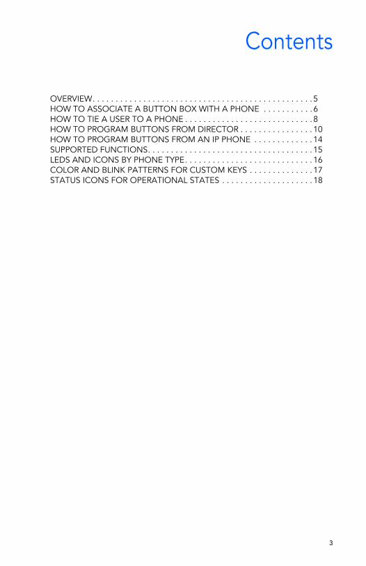
Contents
OVERVIEW. . . . . . . . . . . . . . . . . . . . . . . . . . . . . . . . . . . . . . . . . . . . . . . . 5HOW TO ASSOCIATE A BUTTON BOX WITH A PHONE . . . . . . . . . . . 6HOW TO TIE A USER TO A PHONE . . . . . . . . . . . . . . . . . . . . . . . . . . . . 8HOW TO PROGRAM BUTTONS FROM DIRECTOR . . . . . . . . . . . . . . . . 10HOW TO PROGRAM BUTTONS FROM AN IP PHONE . . . . . . . . . . . . . 14SUPPORTED FUNCTIONS. . . . . . . . . . . . . . . . . . . . . . . . . . . . . . . . . . . . 15LEDS AND ICONS BY PHONE TYPE. . . . . . . . . . . . . . . . . . . . . . . . . . . . 16COLOR AND BLINK PATTERNS FOR CUSTOM KEYS . . . . . . . . . . . . . . 17STATUS ICONS FOR OPERATIONAL STATES . . . . . . . . . . . . . . . . . . . . 18
3

4
OVERVIEWThe programmable buttons allow an administrator or an end user to change the functions associated with the custom buttons on some IP phones and on the button box. This lets the user create shortcuts for operations that would normally require pressing two or three buttons.
For example, the action associated with the bottom button on an IP 560 could be configured to speed-dial a particular extension or external number. The button above that could be set to perform overhead paging, and so on. All of the custom buttons on the IP 560 phone are configurable except for the top-most button, which is permanently set to provide call appearance information (i.e. ringing indicator and call timer information). All 24 buttons on the button box (BB24) are configurable with none limited to call appearance.
Users can figure out which actions they perform on a regular basis and then associate those actions with the custom buttons so that instead of having to dial a star code (such as *14 for picking up the Night Bell) they can just press one button. See the table on the following page for supported functions.
Details:
• After a function is assigned to a button, users can enter a label (up to five characters on the IP 560 and up to six characters on the IP 100 and BB24). The label appears on the LED display next to the custom button.
• The system administrator can configure the custom buttons via ShoreWare Director on behalf of a user or can enable permissions for an individual user so that the user can modify the custom buttons on the IP phone via the telephone interface.
• The programmable button feature is supported on the BB24, IP 100, IP 212k, IP 230, and IP 560 models. The feature is not supported on the analog models or on the IP 210.
• The IP100 does not have custom buttons, but the soft keys can be configured (via ShoreWare Director) in the same way that custom buttons are configured on the other phones.
• IP 100 phones cannot be configured by the user. The buttons on these phones must be configured by the system administrator.
5
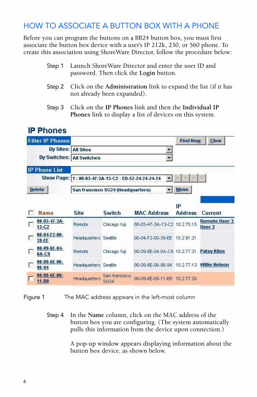
HOW TO ASSOCIATE A BUTTON BOX WITH A PHONEBefore you can program the buttons on a BB24 button box, you must first associate the button box device with a user’s IP 212k, 230, or 560 phone. To create this association using ShoreWare Director, follow the procedure below:
Step 1 Launch ShoreWare Director and enter the user ID and password. Then click the Login button.
Step 2 Click on the Administration link to expand the list (if it has not already been expanded).
Step 3 Click on the IP Phones link and then the Individual IP Phones link to display a list of devices on this system.
Figure 1 The MAC address appears in the left-most column
Step 4 In the Name column, click on the MAC address of the button box you are configuring. (The system automatically pulls this information from the device upon connection.)
A pop-up window appears displaying information about the button box device, as shown below.
6
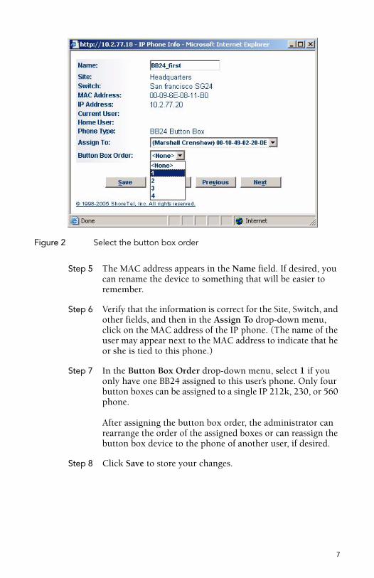
Figure 2 Select the button box order
Step 5 The MAC address appears in the Name field. If desired, you can rename the device to something that will be easier to remember.
Step 6 Verify that the information is correct for the Site, Switch, and other fields, and then in the Assign To drop-down menu, click on the MAC address of the IP phone. (The name of the user may appear next to the MAC address to indicate that he or she is tied to this phone.)
Step 7 In the Button Box Order drop-down menu, select 1 if you only have one BB24 assigned to this user’s phone. Only four button boxes can be assigned to a single IP 212k, 230, or 560 phone.
After assigning the button box order, the administrator can rearrange the order of the assigned boxes or can reassign the button box device to the phone of another user, if desired.
Step 8 Click Save to store your changes.
7
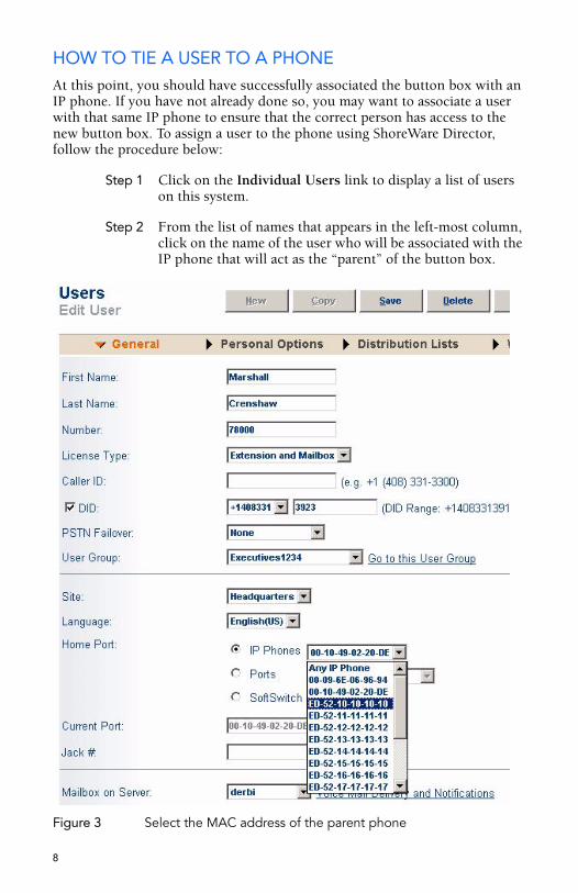
HOW TO TIE A USER TO A PHONEAt this point, you should have successfully associated the button box with an IP phone. If you have not already done so, you may want to associate a user with that same IP phone to ensure that the correct person has access to the new button box. To assign a user to the phone using ShoreWare Director, follow the procedure below:
Step 1 Click on the Individual Users link to display a list of users on this system.
Step 2 From the list of names that appears in the left-most column, click on the name of the user who will be associated with the IP phone that will act as the “parent” of the button box.
Figure 3 Select the MAC address of the parent phone
8
Step 3 Select the MAC address of the user’s phone from the Home Port - IP Phones drop-down menu, as shown.
Step 4 Click Save to store your changes.
You are now ready to move on to the next section, which provides information on programming the buttons on your BB24 button box.
9
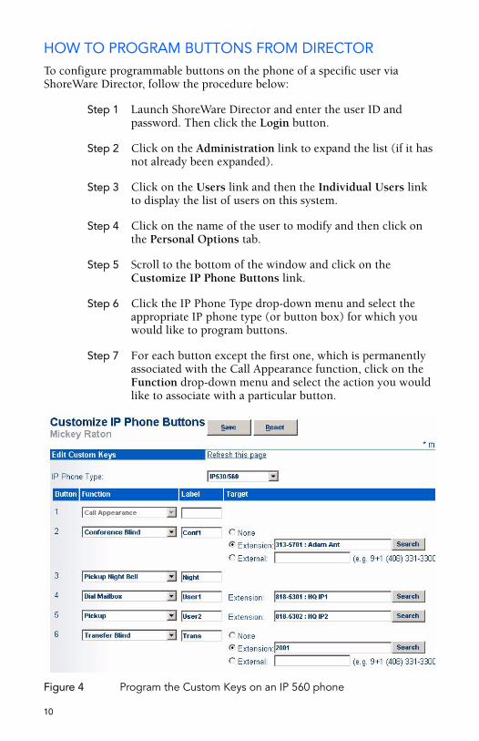
HOW TO PROGRAM BUTTONS FROM DIRECTORTo configure programmable buttons on the phone of a specific user via ShoreWare Director, follow the procedure below:
Step 1 Launch ShoreWare Director and enter the user ID and password. Then click the Login button.
Step 2 Click on the Administration link to expand the list (if it has not already been expanded).
Step 3 Click on the Users link and then the Individual Users link to display the list of users on this system.
Step 4 Click on the name of the user to modify and then click on the Personal Options tab.
Step 5 Scroll to the bottom of the window and click on the Customize IP Phone Buttons link.
Step 6 Click the IP Phone Type drop-down menu and select the appropriate IP phone type (or button box) for which you would like to program buttons.
Step 7 For each button except the first one, which is permanently associated with the Call Appearance function, click on the Function drop-down menu and select the action you would like to associate with a particular button.
Figure 4 Program the Custom Keys on an IP 560 phone
10
Step 8 In the Label field to the left of the drop-down menu, enter a descriptive word to remind the user which function is associated with that button. This label will appear on the LED display adjacent to the button. Note that this label can be up to five characters long for the IP 212k, 230, and 560 phones and up to six characters long for the IP 100 phone and BB24 device.
Step 9 After you have selected a function and entered a label for a particular button, you may optionally enter destination information in the Target field. Certain functions, such as “record call” do not require entering a destination, but other functions such as speed-dial or blind transfer can optionally take a destination. Some functions take only extensions and some take any type of phone number.
Step 10 When you have finished entering functions and labels for all of the buttons, click the Save button at the top of the window to store your changes.
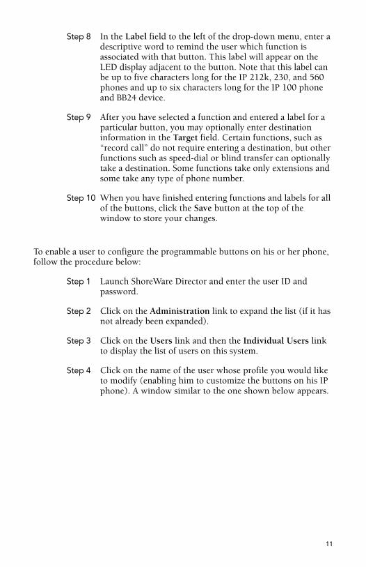
To enable a user to configure the programmable buttons on his or her phone, follow the procedure below:
Step 1 Launch ShoreWare Director and enter the user ID and password.
Step 2 Click on the Administration link to expand the list (if it has not already been expanded).
Step 3 Click on the Users link and then the Individual Users link to display the list of users on this system.
Step 4 Click on the name of the user whose profile you would like to modify (enabling him to customize the buttons on his IP phone). A window similar to the one shown below appears.
11
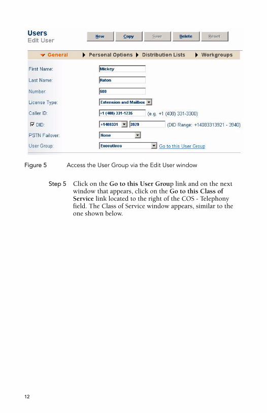
Figure 5 Access the User Group via the Edit User window
Step 5 Click on the Go to this User Group link and on the next window that appears, click on the Go to this Class of Service link located to the right of the COS - Telephony field. The Class of Service window appears, similar to the one shown below.
12
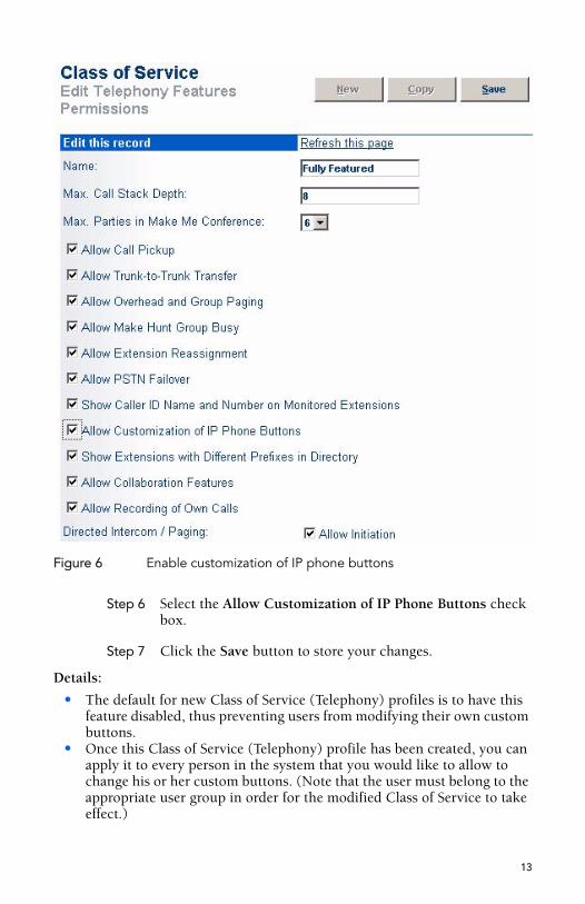
Figure 6 Enable customization of IP phone buttons
Step 6 Select the Allow Customization of IP Phone Buttons check box.
Step 7 Click the Save button to store your changes.
Details:
• The default for new Class of Service (Telephony) profiles is to have this feature disabled, thus preventing users from modifying their own custom buttons.
• Once this Class of Service (Telephony) profile has been created, you can apply it to every person in the system that you would like to allow to change his or her custom buttons. (Note that the user must belong to the appropriate user group in order for the modified Class of Service to take effect.)
13
HOW TO PROGRAM BUTTONS FROM AN IP PHONETo change the custom buttons on your IP 212k, 230, 560 phone or BB24 device via the telephone interface, follow the procedure below:
Step 1 Press the Options button on your IP phone and enter your password, followed by the # key or OK soft key.
Step 2 Scroll through the list to option 4. Program Buttons, or press 4 on the keypad.
Step 3 Press the Edit soft key.
Step 4 Press the custom button that you would like to modify. (If you are modifying the buttons on the BB24 device via the 212k/230/560 interface, press the button on the BB24 that you would like to configure.)
Step 5 Scroll through the list of functions until you find the function that you would like to apply to this button.
NOTE Your choices are limited to just Call Appearance and Dial Number (i.e. Speed Dial) when programming the buttons via the 212k/230 interface. This limitation does not apply to the IP 560 phone. To program one of the other functions, contact your system administrator.
Step 6 When you have highlighted the appropriate function, press the Next soft key.
Step 7 Enter an extension, external number, or leave it blank. Then, press the Next soft key.
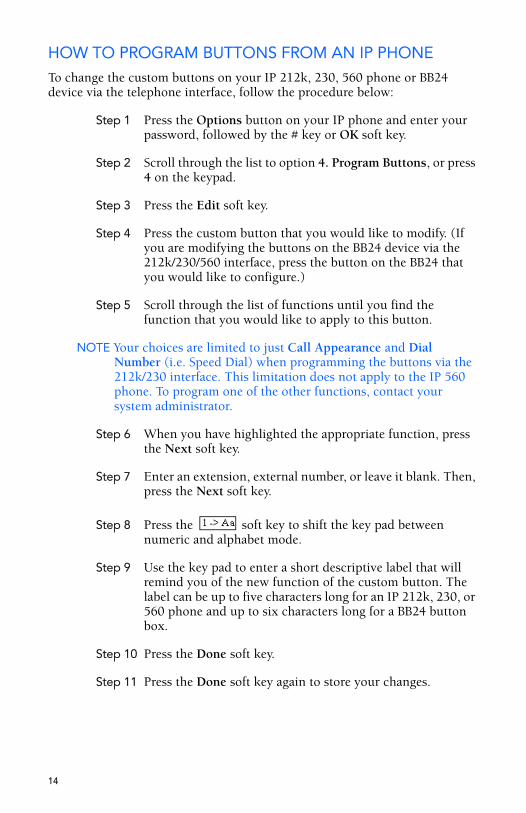
Step 8 Press the soft key to shift the key pad between numeric and alphabet mode.
Step 9 Use the key pad to enter a short descriptive label that will remind you of the new function of the custom button. The label can be up to five characters long for an IP 212k, 230, or 560 phone and up to six characters long for a BB24 button box.
Step 10 Press the Done soft key.
Step 11 Press the Done soft key again to store your changes.
14
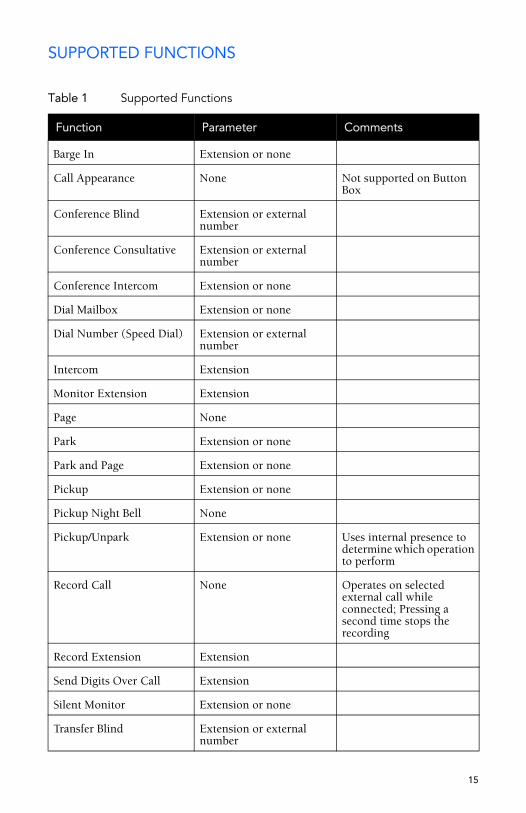
SUPPORTED FUNCTIONS
Table 1 Supported Functions
Function Parameter Comments
Barge In Extension or none
Call Appearance None Not supported on Button Box
Conference Blind Extension or external number
Conference Consultative Extension or external number
Conference Intercom Extension or none
Dial Mailbox Extension or none
Dial Number (Speed Dial) Extension or external number
Intercom Extension
Monitor Extension Extension
Page None
Park Extension or none
Park and Page Extension or none
Pickup Extension or none
Pickup Night Bell None
Pickup/Unpark Extension or none Uses internal presence to determine which operation to perform
Record Call None Operates on selected external call while connected; Pressing a second time stops the recording
Record Extension Extension
Send Digits Over Call Extension
Silent Monitor Extension or none
Transfer Blind Extension or external number
15
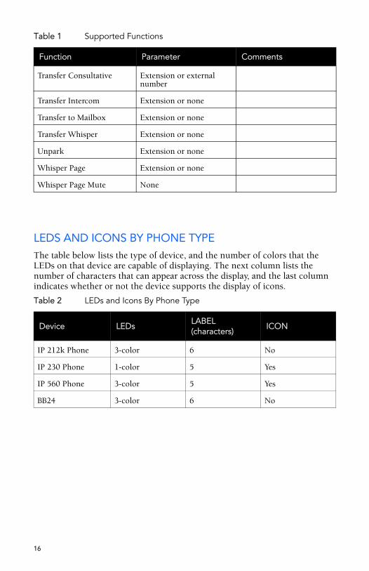
LEDS AND ICONS BY PHONE TYPEThe table below lists the type of device, and the number of colors that the LEDs on that device are capable of displaying. The next column lists the number of characters that can appear across the display, and the last column indicates whether or not the device supports the display of icons.
Transfer Consultative Extension or external number
Transfer Intercom Extension or none
Transfer to Mailbox Extension or none
Transfer Whisper Extension or none
Unpark Extension or none
Whisper Page Extension or none
Whisper Page Mute None
Table 2 LEDs and Icons By Phone Type
Device LEDsLABEL (characters)
ICON
IP 212k Phone 3-color 6 No
IP 230 Phone 1-color 5 Yes
IP 560 Phone 3-color 5 Yes
BB24 3-color 6 No
Table 1 Supported Functions
Function Parameter Comments
16
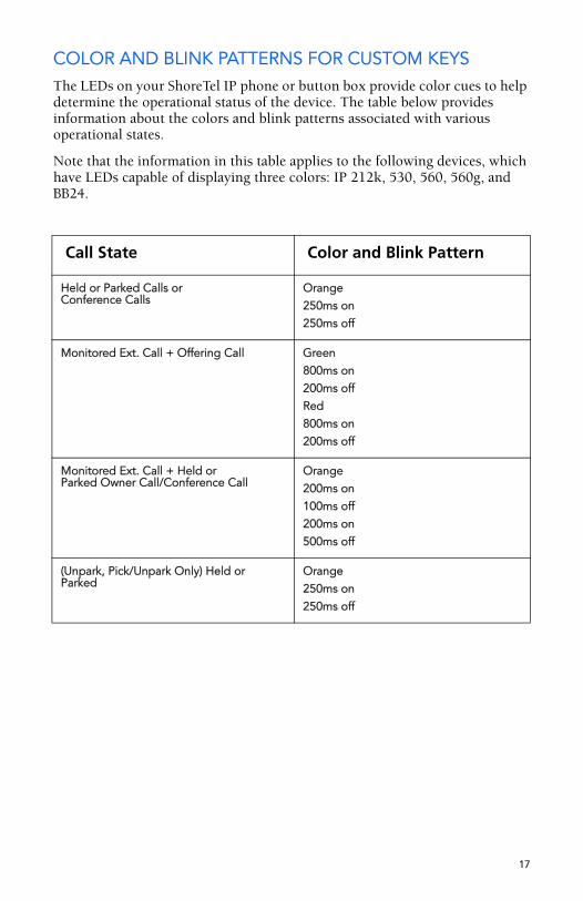
COLOR AND BLINK PATTERNS FOR CUSTOM KEYSThe LEDs on your ShoreTel IP phone or button box provide color cues to help determine the operational status of the device. The table below provides information about the colors and blink patterns associated with various operational states.
Note that the information in this table applies to the following devices, which have LEDs capable of displaying three colors: IP 212k, 530, 560, 560g, and BB24.
Call State Color and Blink Pattern
Held or Parked Calls or Conference Calls
Orange250ms on250ms off
Monitored Ext. Call + Offering Call Green800ms on200ms offRed800ms on200ms off
Monitored Ext. Call + Held orParked Owner Call/Conference Call
Orange200ms on100ms off200ms on500ms off
(Unpark, Pick/Unpark Only) Held orParked
Orange250ms on250ms off
17
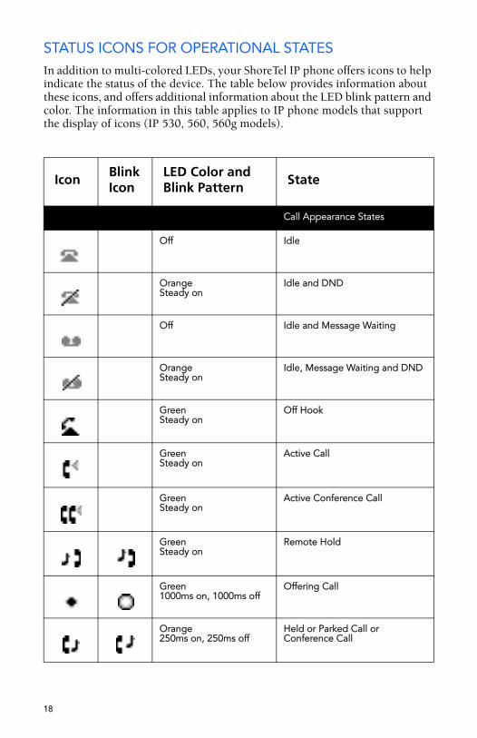
STATUS ICONS FOR OPERATIONAL STATESIn addition to multi-colored LEDs, your ShoreTel IP phone offers icons to help indicate the status of the device. The table below provides information about these icons, and offers additional information about the LED blink pattern and color. The information in this table applies to IP phone models that support the display of icons (IP 530, 560, 560g models).
Icon BlinkIcon
LED Color and Blink Pattern
State
Call Appearance States
Off Idle
OrangeSteady on
Idle and DND
Off Idle and Message Waiting
OrangeSteady on
Idle, Message Waiting and DND
GreenSteady on
Off Hook
GreenSteady on
Active Call
GreenSteady on
Active Conference Call
GreenSteady on
Remote Hold
Green1000ms on, 1000ms off
Offering Call
Orange250ms on, 250ms off
Held or Parked Call or Conference Call
18
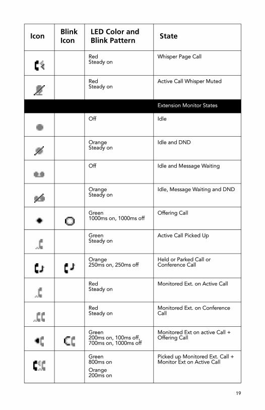
RedSteady on
Whisper Page Call
RedSteady on
Active Call Whisper Muted
Extension Monitor States
Off Idle
OrangeSteady on
Idle and DND
Off Idle and Message Waiting
OrangeSteady on
Idle, Message Waiting and DND
Green1000ms on, 1000ms off
Offering Call
GreenSteady on
Active Call Picked Up
Orange250ms on, 250ms off
Held or Parked Call or Conference Call
RedSteady on
Monitored Ext. on Active Call
RedSteady on
Monitored Ext. on Conference Call
Green200ms on, 100ms off, 700ms on, 1000ms off
Monitored Ext on active Call + Offering Call
Green800ms onOrange200ms on
Picked up Monitored Ext. Call + Monitor Ext on Active Call
Icon BlinkIcon
LED Color and Blink Pattern
State
19
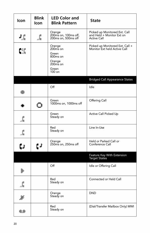
Orange200ms on, 100ms off,200ms on, 500ms off
Picked up Monitored Ext. Call and Held + Monitor Ext on Active Call
Orange200ms onGreen800ms onOrange200ms onGreen100 on
Picked up Monitored Ext. Call + Monitor Ext held Active Call
Bridged Call Appearance States
Off Idle
Green1000ms on, 1000ms off
Offering Call
GreenSteady on
Active Call Picked Up
RedSteady on
Line In-Use
Orange250ms on, 250ms off
Held or Parked Call or Conference Call
Feature Key With Extension Target States
Off Idle or Offering Call
RedSteady on
Connected or Held Call
OrangeSteady on
DND
RedSteady on
(Dial/Transfer Mailbox Only) MWI
Icon BlinkIcon
LED Color and Blink Pattern State
20
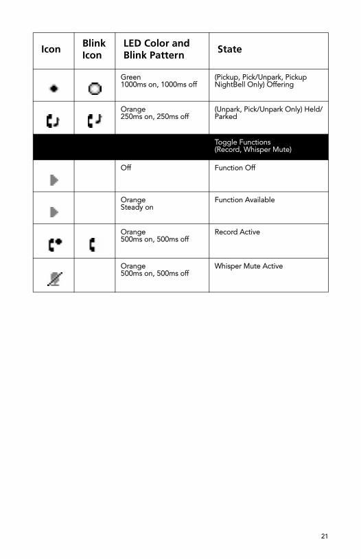
Green1000ms on, 1000ms off
(Pickup, Pick/Unpark, Pickup NightBell Only) Offering
Orange250ms on, 250ms off
(Unpark, Pick/Unpark Only) Held/Parked
Toggle Functions(Record, Whisper Mute)
Off Function Off
OrangeSteady on
Function Available
Orange500ms on, 500ms off
Record Active
Orange500ms on, 500ms off
Whisper Mute Active
Icon BlinkIcon
LED Color and Blink Pattern
State
21

22