programmable control students notes - picaxe forum · web viewprogrammable control contents...
TRANSCRIPT

Revised Standard Grade Technological Studies
Programmable Control

Contents
Students’ Notes 1Section 1: Electronic Control Systems 3Section 2: The Stamp Controller 11Section 3: Inside a Microcontroller 27Section 4: Using Inputs 44Section 5: Number Systems 55Section 6: Stepper Motors 58Section 7: Analogue Sensors 62Section 8: Project Assignments 69
Teacher’s Notes 73Introduction 75General Notes on Using the Stamp Controller 76Serial Port Information for PC Users 78Standard Programming Format 80PBASIC Commands 81Equipment List 82Software and Minimum Computer Specifications 86Contact Addresses 87Answers to Assignments 88
Programming with PBASIC 137Programming with PBASIC 139
Switching outputs on and off 139Detecting inputs 140Using symbols 141‘For … next’ loops 142Sub-procedures 143
Data sheets 144Input module 144Two digital inputs and two analogue sensors 146Output Driver module 148
Standard Grade Technological Studies: Programmable Controlii

Students’ Notes
Standard Grade Technological Studies: Programmable Control – Students’ Notes 1

Contents
Section 1: Electronic Control Systems 3Introduction 3System diagrams 4Case study – an electronic toy 5What is a microcontroller? 9
Section 2: The Stamp Controller 11Summary – programming procedure 12Downloading a sample program 13Windows software instructions 14Flowcharts 15Continuous loops 16Converting a flowchart into a control program 19Continuous loops 21Using symbols 23
Section 3: Inside a Microcontroller 27Memory (ROM and RAM) 28Arithmetic/logic unit (ALU) and clock 28Buses 28Connecting output transducers to the stamp controller 29The motor driver 31Noise suppression capacitors 31Controlling motors 32Speed control of d.c. motors 34For … next loops 37Sub-procedures 42
Section 4: Using Inputs 44Digital sensors 44The input module 45
Section 5: Number Systems 55Notation 56Bits and bytes 56Converting decimal to binary 57
Section 6: Stepper Motors 58Section 7: Analogue Sensors 62
Light-dependent resistor (LDR) 63Thermistor 64Variable resistor (potentiometer) 64The input module 65
Section 8: Project Assignments 69Project briefs 69PBASIC commands 71
Standard Grade Technological Studies: Programmable Control – Students’ Notes2

Section 1: Electronic Control Systems
Introduction
Many electronic devices have been developed to make life easier (for example a microwave), to make life safer (for example traffic lights), to help with work (for example a computer) and for entertainment purposes (for example computer games consoles).
Some of these devices are purely electronic devices (for example a digital watch). However, many of these devices also control mechanisms (for example the eject mechanism in a video recorder) and so can be described as mechatronic devices.
However, both electronic and mechatronic devices all have one thing in common – an electronic control system.
Any electronic control system can be broken down into three distinct parts. This can be shown as a block diagram containing INPUT – PROCESS – OUTPUT blocks.
Assignment 1.1(a) List three electronic devices.(b) List three mechatronic devices. Explain the ‘mechanism’ in each of the three
mechatronic devices listed.
Standard Grade Technological Studies: Programmable Control – Students’ Notes 3

System diagrams
A system diagram is a more detailed block diagram that also shows the real-world input signals (for example light or heat) and the real-world output signals (for example movement or sound).
Therefore, the system diagram for a warning device for a freezer in a restaurant would be drawn as below. The buzzer would sound if the temperature in the freezer passed a certain level.
Standard Grade Technological Studies: Programmable Control – Students’ Notes4

Case study – an electronic toy
A popular electronic toy is shown above. This is a good example of a mechatronic system, as it uses an electronic circuit to control a number of mechanisms. It also contains a number of sensors so that it can react to changes when it is moved (for example being put in a dark place or being turned upside down).
Standard Grade Technological Studies: Programmable Control – Students’ Notes 5
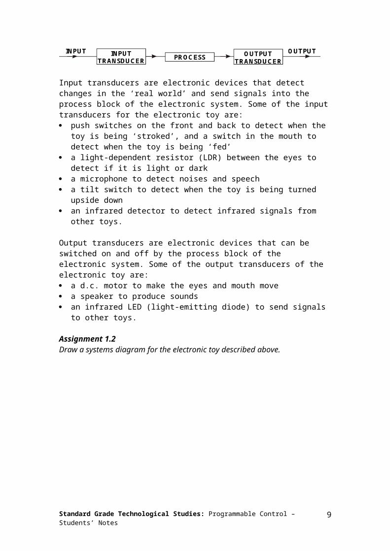
Input transducers are electronic devices that detect changes in the ‘real world’ and send signals into the process block of the electronic system. Some of the input transducers for the electronic toy are: push switches on the front and back to detect when the toy is being ‘stroked’, and
a switch in the mouth to detect when the toy is being ‘fed’ a light-dependent resistor (LDR) between the eyes to detect if it is light or dark a microphone to detect noises and speech a tilt switch to detect when the toy is being turned upside down an infrared detector to detect infrared signals from other toys.
Output transducers are electronic devices that can be switched on and off by the process block of the electronic system. Some of the output transducers of the electronic toy are: a d.c. motor to make the eyes and mouth move a speaker to produce sounds an infrared LED (light-emitting diode) to send signals to other toys.
Assignment 1.2Draw a systems diagram for the electronic toy described above.
Standard Grade Technological Studies: Programmable Control – Students’ Notes6

Assignment 1.3List the input and output transducers for the following devices.
(a) Washing machine
(b) Personal stereo
Standard Grade Technological Studies: Programmable Control – Students’ Notes 7

(c) Vending machine
P op
F i zzy
K olah
J ui ce
Ginger
Y uk
(d) Hairdryer
Standard Grade Technological Studies: Programmable Control – Students’ Notes8

What is a microcontroller?
A microcontroller is often described as a ‘computer-on-a-chip’. Microcontrollers have a controller and memory all built into a single chip. As they are small and inexpensive they can easily be built into other devices to make these products more intelligent and easier to use.
Microcontrollers are usually programmed for a specific electronic product for instance, a microwave oven may use a single microcontroller to process information from the keypads, display user information on the seven-segment display or control the output devices (turntable motor, light, bell and magnetron).
Standard Grade Technological Studies: Programmable Control – Students’ Notes 9
Microcontrollers are single-chip ‘computers’ designed to control specific processes or products. The microcontroller is programmed with a program to complete the desired task. By altering this program, the same ‘brand’ of microcontroller can be used to complete different tasks. The same microcontroller device can therefore be used in a range of different products by simply programming it with a different program.
One microcontroller can often replace a number of separate parts, or even a complete electronic circuit. Some of the advantages of using microcontrollers in a product design are: increased reliability and reduced quantity of stock (as one microcontroller replaces
several parts) simplified product assembly and smaller end products greater product flexibility and adaptability since features are programmed into the
microcontroller and not built into the electronic hardware rapid product changes or development by changing the program and not the
electronic hardware.
Applications that use microcontrollers include household appliances (for example a microwave), alarm systems (for example a fire alarm), medical equipment (for example an incubator for premature babies) and electronic equipment (for example a computer mouse).
Assignment 1.4List the advantages of using a microcontroller within a product design.
Assignment 1.5List three devices that may contain a microcontroller. Explain why you think it would be useful to have a microcontroller in these devices.
Standard Grade Technological Studies: Programmable Control – Students’ Notes10

Section 2: The Stamp Controller
The stamp controller system consists of three main components.
The ‘Basic Stamp’ softwareThis software runs on a computer and allows you to use the computer keyboard to type in programs.
The serial cableThis is the cable that connects the computer to the stamp controller. The cable needs to be connected only when downloading programs. It does not have to be connected when the stamp controller is running because the program is stored on the stamp controller board – even when the power supply is removed!
The stamp controller
Standard Grade Technological Studies: Programmable Control – Students’ Notes 11

The stamp controller ‘runs’ programs that have been downloaded to it. It has indicator LEDs to show which outputs and inputs are on or off, and has connectors for the input and output modules.
The ‘brain’ of the stamp controller board is the 18-pin microcontroller chip in the centre of the board. The program is stored in the 8-pin EEPROM (Electronically Erasable Programmable Read Only Memory) chip. This type of memory can be reprogrammed when desired, but it also keeps the program when the power supply is removed. This means the stamp controller will start to run the program currently in the memory whenever the power supply is connected.
When the power supply is connected to the stamp controller board, the microcontroller ‘reads’ the program from the EEPROM memory chip. It then carries out the program as instructed. The program can contain instructions (‘commands’) to switch outputs on and off, to react to inputs or to pause for time delays. The stamp controller is extremely fast – it can process over 1000 instructions in a second!
Summary programming procedure
1. Draw a flowchart for the control task.2. Write the program on the computer using the Stamp software.3. Connect the download cable from the computer to the stamp controller.4. Connect the power supply to the stamp controller.5. Use the Stamp software to download the program. The download cable can then be
removed after the download.
The program will start running on the stamp controller automatically. However, the program can also be restarted at any time by pressing the reset switch.
Standard Grade Technological Studies: Programmable Control – Students’ Notes12

Downloading a sample program
The following PBASIC program switches pin 7 on and off every second. When you download this program, the red LED 7 on the stamp controller should flash on and off every second.
main:high 7pause 1000low 7pause 1000goto main
This program uses the ‘high’ and ‘low’ commands to control pin 7, and uses the ‘pause’ command to make a delay.
The last ‘goto main’ command makes the program ‘jump’ back to the label ‘main’ at the start of the program. This means the program loops forever. Note that the first time the label is used it must be followed by the colon (:) symbol. This tells the computer that the word is a new label.
Activity 2.aStart up the Stamp software and key in the program above. Save the program and then download it to the stamp controller by clicking ‘Run’. See the instruction sheets on the next two pages, which explain how to do this for both the Windows and Acorn Stamp software.
If you have the stamp controller connected correctly, after a few seconds you should see a ‘download successful’ message on the computer screen, and the red LED 7 on the stamp controller should start flashing.
If you get an error message check that you have not made a spelling mistake in the program, and that the stamp controller is connected to both the power supply and the computer.
Important note: if the computer gives an error message on the line containing ‘switch’ you may have the software in the wrong mode. Check that the software is in ‘PBASIC’ mode.
Standard Grade Technological Studies: Programmable Control – Students’ Notes 13

Windows software instructions
Toolbar short cuts
To download/run a program:1. check that the download cable is connected to the stamp controller and the
computer’s serial port2. check that the power supply/battery is connected to the stamp controller3. click ‘Run’ (or the toolbar icon).
To save a program:1. click ‘File’ ‘Save As’… (or the toolbar icon)2. type in a filename (up to eight letters, no spaces or punctuation)3. click <OK>.
To open a saved program:1. click ‘File’ ‘Open’ … (or the toolbar icon)2. select a filename from the list by clicking on it3. click <OK>.
To start a new program:1. click ‘File’ – ‘New’.
To print a program:1. click ‘File’ – ‘Print’ … (or the toolbar icon)2. if you want each program line printed to have a number, make sure the ‘Print Line
Numbers’ box is selected3. click <OK>.
Standard Grade Technological Studies: Programmable Control – Students’ Notes14

Flowcharts
Flowcharts are commonly used to explain how a program works. As flowcharts are drawn graphically they often make programs easier to understand. A flowchart should be drawn for each program you develop.
A simple flowchart is shown below.
The flowchart shown uses three different symbols.
Start/stop symbolThe ‘Start’ or ‘Stop’ symbol shape is a rectangle with rounded ends. Each flowchart must contain only one ‘Start’ symbol and, usually, only one ‘Stop’ symbol.
Wait symbolThe ‘Wait’ symbol is a rectangle. The text inside the symbol explains how long the time delay is.
Outputs symbolThe ‘Outputs’ symbol is a parallelogram. The text inside the symbol explains which output pins are switched on or off at any time.
Standard Grade Technological Studies: Programmable Control – Students’ Notes 15

Continuous loops
START
SWITC H PIN 7HIG H
SWITC H PIN 6HIG H
SWITC H PINS 4 5HIG H
&
WAIT 2 SEC O NDS
SWITC H ALLO FF
WAIT 3 SEC O NDS
WAIT 1 SEC O ND
WAIT 1 SEC O ND
Sometimes it is necessary to create programs that loop ‘forever’, as is the case in this flowchart. There is no ‘Stop’ symbol because the program never ends!
Standard Grade Technological Studies: Programmable Control – Students’ Notes16

Assignment 2.3
A set of temporary traffic lights is required for a system of roadworks.
red 10 sred and amber 2 sgreen 10 samber 2 s
Draw a flowchart for the lights sequence shown by one set of traffic lights. Use the times shown in the table for each stage.
Assignment 2.4A microwave oven operates with the following sequence. Draw a flowchart for this sequence.
1) Light on2) Turntable on3) Magnetron on4) Wait 30 seconds5) Magnetron off6) Wait 10 seconds7) Turntable off8) Buzzer on9) Wait 0.5 second10) Buzzer off11) Light off
Standard Grade Technological Studies: Programmable Control – Students’ Notes 17

Assignment 2.5The flowchart for the movement of a robot buggy is shown below.
Draw the path you would expect the robot buggy to take. For how long is the robot buggy moving?
Standard Grade Technological Studies: Programmable Control – Students’ Notes18

Converting a flowchart into a control program
Once a flowchart has been drawn it is necessary to convert it into the stamp controller programming language, which is called PBASIC.
START
SWITC H PIN 7HIG H
SWITC H PIN 6HIG H
SWITC H PINS 4 5HIG H
&
WAIT 2 SEC O NDS
SWITC H ALLO FF
WAIT 3 SEC O NDS
STO P
WAIT 1 SEC O ND
Standard Grade Technological Studies: Programmable Control – Students’ Notes 19

A PBASIC program for the flowchart shown on the previous page is:
main:high 7 ' switch pin 7 onpause 2000 ' wait for 2 secondshigh 6 ' switch pin 6 onpause 1000 ' wait for 1 secondhigh 5 ' switch pin 5 onhigh 4 ' switch pin 4 onpause 3000 ' wait for 3 secondslow 7 ' switch pin 7 offlow 6 ' switch pin 6 offlow 5 ' switch pin 5 offlow 4 ' switch pin 4 offend ' end the program
Note that some flowchart symbols require more than one line of PBASIC code. Also remember that comments (an explanation after the apostrophe (') symbol) make each line of a PBASIC program much easier to understand. These comments are ignored by the computer when it downloads a program to the stamp controller.
A label (for example ‘main:’ in the program above) can be any word (apart from keywords such as ‘high’), but it must begin with a letter. When the label is first defined it must end with a colon (:). The colon ‘tells’ the computer that the word is a new label.
Activity 2.cKey in the program listed above, and then download it to the stamp controller.
The LED indicator on pin 7 should light first, followed by the LED on pin 6 and then the LEDs on pins 4 and 5. The program will then stop. To rerun the program, simply press the ‘reset’ switch on the stamp controller.
Read through the program carefully and make sure you understand exactly what each program line achieves.
Note the ‘comments’ at the end of each line. A comment starts after an apostrophe (') and continues to the end of the line. Although the comments are not needed to make the program work, they are an essential part of the program as they explain in ‘plain language’ what the program is doing. You should always add a comment to every line of your program, particularly if the program is to be studied by someone else at a later date.
Standard Grade Technological Studies: Programmable Control – Students’ Notes20

Continuous loops
START
SWITC H PIN 7HIG H
SWITC H PIN 6HIG H
SWITC H PINS 4 5HIG H
&
WAIT 2 SEC O NDS
SWITC H ALLO FF
WAIT 3 SEC O NDS
WAIT 1 SEC O ND
WAIT 1 SEC O ND
A PBASIC program that would achieve this control operation is listed below.
main:high 7 ' switch pin 7 onpause 2000 ' wait for 2 secondshigh 6 ' switch pin 6 onpause 1000 ' wait for 1 secondhigh 5 ' switch pin 5 onhigh 4 ' switch pin 4 onpause 3000 ' wait for 3 secondslow 7 ' switch pin 7 offlow 6 ' switch pin 6 offlow 5 ' switch pin 5 offlow 4 ' switch pin 4 offpause 1000 ' wait for 1 secondgoto main ' jump back to start
Standard Grade Technological Studies: Programmable Control – Students’ Notes 21

Activity 2.dKey in, download and run the program listed above.
At the start of this program is a label called ‘main’. Note that all address labels must end with a colon (:) when they are first used in a program.
The last line ‘goto main’ causes the program to ‘jump back’ to the first line labelled ‘main’. This means that this program will loop ‘forever’. Note that when ‘main’ is typed after a ‘goto’ command it does not need a colon.
This program again uses the ‘pause’ command. This creates a short time delay (measured in milliseconds thousandths of a second) ‘pause’ can be followed by a number between 1 and 65535.
It is also a good programming technique to use tabs (or spaces) at the start of lines without labels so that all the commands are neatly aligned. The term ‘white-space’ is used by programmers to define tabs, spaces and blank lines, and the correct use of white-space can make the program listing much easier to read and understand.
Note: some early BASIC languages used ‘line numbers’ rather than labels for ‘goto’ commands. Unfortunately, this line number system can be inconvenient to use, because if you modify your program by later adding, or removing, lines of code you then have to modify all the line numbers within the ‘goto’ commands accordingly. The label system, as used in most modern BASIC languages, overcomes this problem automatically.
Standard Grade Technological Studies: Programmable Control – Students’ Notes22

Using symbols
Sometimes it can be hard to remember which pins are connected to which devices. The ‘symbol’ command can then be used at the start of a program to rename the inputs and outputs.
symbol red = 7 ' rename 7 ‘red’symbol green = 5 ' rename 5 ‘green’
main: ' make a label called ‘main’high red ' red LED onlow green ' green LED offpause 1000 ' wait 1 secondlow red ' red LED offhigh green ' green LED onpause 1000 ' wait 1 secondgoto main ' jump back to the start
Activity 2.eKey in the program listed above, and then download it to the stamp controller.
The red and green LEDs should flash alternately.
Read through the program carefully, and make sure you understand exactly what each program line achieves.
Standard Grade Technological Studies: Programmable Control – Students’ Notes 23

Assignment 2.6
A set of temporary traffic lights is required for a system of road works.
red 10 sred and amber 2 sgreen 10 samber 2 s
Draw a flowchart for the lights sequence shown by one set of the traffic lights. Use the times shown in the table for each stage.
Write a PBASIC program, using ‘high’ and ‘low’ commands, to achieve this operation. Use the following pin configuration red (7), amber (6) and green (5).
Standard Grade Technological Studies: Programmable Control – Students’ Notes24

Assignment 2.7What is meant by the term ‘white-space’? Why is it important to use white-space and comments when writing programs? Why is it important to add comments to programs?
Assignment 2.8A fountain in a garden centre is to be used to attract visitors to a new range of plastic ponds. The garden centre owner wishes to develop a microcontroller-based system that can be programmed to switch the fountain pump and an external lighting system on and off at regular intervals.
The following PBASIC program will switch the pump on and off every 60 seconds. The lights turn on 10 seconds after the pump has started and turn off 10 seconds before the pump is stopped.
Draw a flowchart for the control sequence and add the missing comments to the program listing.
main: high 7 ' switch the pump onpause 10000 ' wait 10 secondshigh 6 ' switch the lights onpause 40000 ' …low 6 ' …pause 10000 ' …low 7 ' …pause 60000 ' …goto main ' …
Standard Grade Technological Studies: Programmable Control – Students’ Notes 25

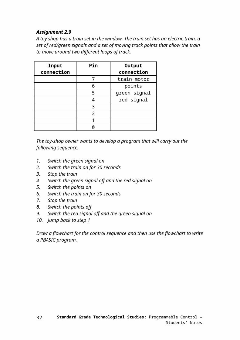
Assignment 2.9A toy shop has a train set in the window. The train set has an electric train, a set of red/green signals and a set of moving track points that allow the train to move around two different loops of track.
Input connection Pin Output connection7 train motor6 points5 green signal4 red signal3210
The toy-shop owner wants to develop a program that will carry out the following sequence.
1. Switch the green signal on2. Switch the train on for 30 seconds3. Stop the train4. Switch the green signal off and the red signal on5. Switch the points on6. Switch the train on for 30 seconds7. Stop the train8. Switch the points off9. Switch the red signal off and the green signal on10. Jump back to step 1
Draw a flowchart for the control sequence and then use the flowchart to write a PBASIC program.
Standard Grade Technological Studies: Programmable Control – Students’ Notes26

Section 3: Inside a Microcontroller
The ‘brain’ of the stamp controller system is the 18-pin microcontroller in the centre of the board. Although microcontrollers are relatively cheap (some microcontrollers cost less than £1), they are very complex devices containing many thousands of transistors, resistors and other electronic components. The microcontroller on the stamp controller has been programmed to read the commands from the EEPROM memory chip and then carry these commands out.
The main features of the microcontroller are shown in the block diagram.
Microcontrollers contain all of these features within a single package, as opposed to microprocessor systems (for example as used in desktop computers), where each block in the diagram above is normally a separate integrated circuit. In general the only component that needs to be added to a microcontroller is a clock resonator, which sets the operating speed of the microcontroller.
Standard Grade Technological Studies: Programmable Control – Students’ Notes 27

Memory (ROM and RAM)
Microcontrollers contain both ROM (permanent memory) and RAM (temporary memory).
The ROM (Read Only Memory) contains the operating instructions (that is, the ‘program’) for the microcontroller. The ROM is ‘programmed’ before the microcontroller is installed in the target system, and the memory retains the information even when the power is removed. The stamp controller board contains a microcontroller whose ROM has been programmed to read the external EEPROM chip and then carry out the instructions it reads.
The RAM (Random Access Memory) is ‘temporary’ memory used for storing information whilst the program is running. This is normally used to store answers to mathematical ‘sums’ the microcontroller carries out as it is working. This memory is ‘volatile’, which means that as soon as the power is disconnected the contents of the memory are lost.
Arithmetic/logic unit (ALU) and clock
The processing unit (full name arithmetic and logic unit (ALU)) is the ‘control centre’ of the microcontroller. It operates by reading instructions from the ROM and then carrying out the mathematical operations for each instruction. The speed at which these operations occur is controlled by the clock circuit.
The clock circuit within the microcontroller ‘synchronises’ all the internal blocks (ALU, ROM, RAM, etc.) so that the whole system works correctly.
Buses
Information is carried between the various blocks of the microcontroller along ‘groups’ of wires called buses. The ‘data bus’ carries data between the ALU and RAM, and the ‘program bus’ carries the program instructions from the ROM to the ALU.
Assignment 3.1Explain the following microcontroller terms: ALU, bus, clock.
Assignment 3.2Explain the differences between the following types of memory:RAM, ROM, EEPROM.
Standard Grade Technological Studies: Programmable Control – Students’ Notes28

Connecting output transducers to the stamp controller
The stamp controller can only drive low-power devices, such as LEDs, directly. It cannot drive devices such as lamps, buzzers, solenoids or motors directly because these devices require a higher current to operate.
A common way to drive these devices is with a transistor, as shown in the diagram above. In this case the lamp is controlled by the transistor switching on and off.
Standard Grade Technological Studies: Programmable Control – Students’ Notes 29

The Output Driver
The output driver module provides four transistor outputs, as in the circuit shown above. Instead of using four separate transistors, the output driver uses an integrated circuit called the ULN2803A, which contains all the transistors in one 18-pin ‘chip’.
To use the transistor outputs, the output device should be connected between the screw-terminal numbered output (4–7) and a V+ connection. The positive (red) wire on polarised devices (for example a buzzer) should be connected to the V+ connection.
The white 6-pin header beside the screw terminals allows a ‘stepper motor’ or control model to be connected easily to all four of the outputs.
Standard Grade Technological Studies: Programmable Control – Students’ Notes30

The motor driver
The output driver module also contains a second integrated circuit called the L293D pushpull driver. This chip allows forward and reverse control of two d.c. motors. Each motor output uses two of the stamp controller output pins to control the direction of rotation of the motor.
Pin 4 Pin 5 Motor A Pin 6 Pin 7 Motor Boff off halt off off haltoff on forwards off on forwardson off backwards on off backwardson on halt on on halt
To use the pushpull motor output, the motor should be connected between the screw terminals labelled A or B. If the motor turns in the opposite direction to that expected, the two motor wires should be swapped over.
Noise-suppression capacitors
Some d.c. motors create electrical noise as they rotate. This problem only occurs with some d.c. motors it is not normally a problem with d.c. solar motors. This electrical noise can affect the stamp controller, sometimes causing it to reset and act erratically. Fortunately this problem is very easily solved by connecting a 220 F polyester capacitor directly across the motor terminals. The capacitor smoothes out the electrical noise before it can affect the stamp controller.
Standard Grade Technological Studies: Programmable Control – Students’ Notes 31

Controlling motors
STAM PC O NTR O LLER
O U TPU TD R IVER
M O DU LE
Connect a buggy to the output driver module as shown in the diagram.
The ‘high’ and ‘low’ commands can be used to switch the output pins and control the motors forward, backward and halt.
main: ' make a label called ‘main’high 5 ' motor A forwardhigh 7 ' motor B forwardpause 1000 ' wait 1 secondlow 5 ' motor A haltlow 7 ' motor B haltpause 1000 ' wait 1 secondhigh 4 ' motor A backwardhigh 6 ' motor B backwardpause 1000 ' wait 1 secondlow 4 ' motor A haltlow 6 ' motor B haltgoto main ' jump back to the start
Activity 3.aKey-in the program listed above, and then download it to the stamp controller. The buggy should rock backwards and forwards. If the buggy spins, swap the motor wires over where they connect to the output driver module.
Standard Grade Technological Studies: Programmable Control – Students’ Notes32
Assignment 3.3
STAM PC O NTR O LLER
O U TPU TD R IVER
M O DU LE
Connect a buggy to the output driver module as shown in the diagram.
Write a program to control the movement of the buggy as shown in the flowchart above.
Assignment 3.4Build a maze on the table out of books. Write a PBASIC program to steer the buggy through the maze. Add comments to each line in your program to explain how it works.
Standard Grade Technological Studies: Programmable Control – Students’ Notes 33

Speed control of d.c. motors
There are two ways to control the speed of a d.c. motor. The simplest is to vary the voltage applied to the motor. If, for instance, 3 V is applied to a small d.c. motor it will rotate at a lower speed than if 5 V were applied. Unfortunately the ‘turning power’ (torque) of the motor will also drop, which means the whole motor system will be less powerful.
The second way to control the motor is to always apply the full voltage (for example5 V) across the motor, but then to switch the power supply on and off rapidly. As the power supply is off some of the time, the motor does not receive as much power and so the motor turns more slowly. The advantage of this system is that the torque remains quite high.
This system is called pulse-width modulation (PWM). The time that the power supply is switched on is called the mark time, and the time that the motor is switched off is called the space time. By varying the on (mark)-to-off (space) ratio, the speed of the motor can be varied.
Standard Grade Technological Studies: Programmable Control – Students’ Notes34

Activity 3.b
Connect a d.c. solar motor across the ‘V+’ and ‘7’ terminals on the output driver module. This will provide an interfacing circuit as shown above.
Connect a propeller to the output shaft of the d.c. solar motor to make the rotational speed easier to see.
Key in, download and run the program listed below. This program drives the motor at approximately half speed, as the space (off time) is twice the length of the mark (on time). Note that you must use pause delays, as the power supply must switch on and off very quickly (wait delays would be too long).
main: high 7 ' output highpause 5 ' pause for 5 mslow 7 ' output lowpause 10 ' pause for 10 msgoto main ' loop
Try out different speeds (by experiment) by altering the length of the pause delays.
Assignment 3.5Explain the terms ‘mark’ and ‘space’ in relation to PWM speed control of a d.c. motor.
Assignment 3.6Describe the advantages and disadvantages of using PWM speed control.
Standard Grade Technological Studies: Programmable Control – Students’ Notes 35

Assignment 3.7
Connect the washing machine model to the output driver module. The motor on the washing machine is controlled by outputs 6 and 7 (motor B). Switching output 6 on will make the motor turn one way; switching output 7 on will make the motor turn the other way.
(a) Write a PBASIC program that will make the motor rotate at full speed in each direction for five seconds.
(b) Write a second PBASIC program that will make the motor rotate at half speed in each direction for five seconds. Use PWM speed control for the motor.
Standard Grade Technological Studies: Programmable Control – Students’ Notes36

‘For … next’ loops
It is often useful to repeat the same part of a program a number of times, for instance when flashing an LED. In these cases a ‘for … next’ loop can be used.
In this flowchart the LED connected to output pin 7 is flashed on and off five times. The number of times the code has been repeated is stored that is, stored in the RAM memory of the stamp controller. There are 10 available variables, labelled b0 to b9, which can be used in this way. These variables can also be renamed using the symbol command to make them easier to remember.
Standard Grade Technological Studies: Programmable Control – Students’ Notes
N
Y
START
SET COUNTER = 5
SWITCH PIN 7HIGH
WAIT 1 s
SWITCH PIN 7LOW
HAVE WELOOPED 5
TIMES?
STOP
WAIT 1 s
37

Activity 3.cKey in, download and run the following program.
symbol counter = b0 ' define the variable ‘counter’symbol red = 7 ' define pin 7 with the name ‘red’
main: for counter = 1 to 5 ' start a for … next loop high red ' switch pin 7 high pause 1000 ' wait for 1 second low red ' switch pin 7 low pause 1000 ' wait for 1 secondnext counter ' end of for … next loop
end ' end program
Note again how white-space (extra spaces) has been used to clearly show all the commands that are contained between the ‘for’ and ‘next’ commands.
Standard Grade Technological Studies: Programmable Control – Students’ Notes38

Assignment 3.8
STAM PC O NTR O LLER
O U TPU TD R IVER
M O DU LE
Connect a buggy to the output driver module, as shown in the diagram.
3
3
33
The buggy should follow the path shown in the diagram above, moving in each direction for three seconds.
Draw a flowchart for the movement of the buggy, making use of a ‘for … next’ command structure.
Write a high-level program in PBASIC to control the movement of the buggy as shown by your flowchart. (It will be necessary to experiment with time delays to establish how quickly your buggy turns 90 degrees to the left.)
Standard Grade Technological Studies: Programmable Control – Students’ Notes 39

Assignment 3.9
Standard Grade Technological Studies: Programmable Control – Students’ Notes40

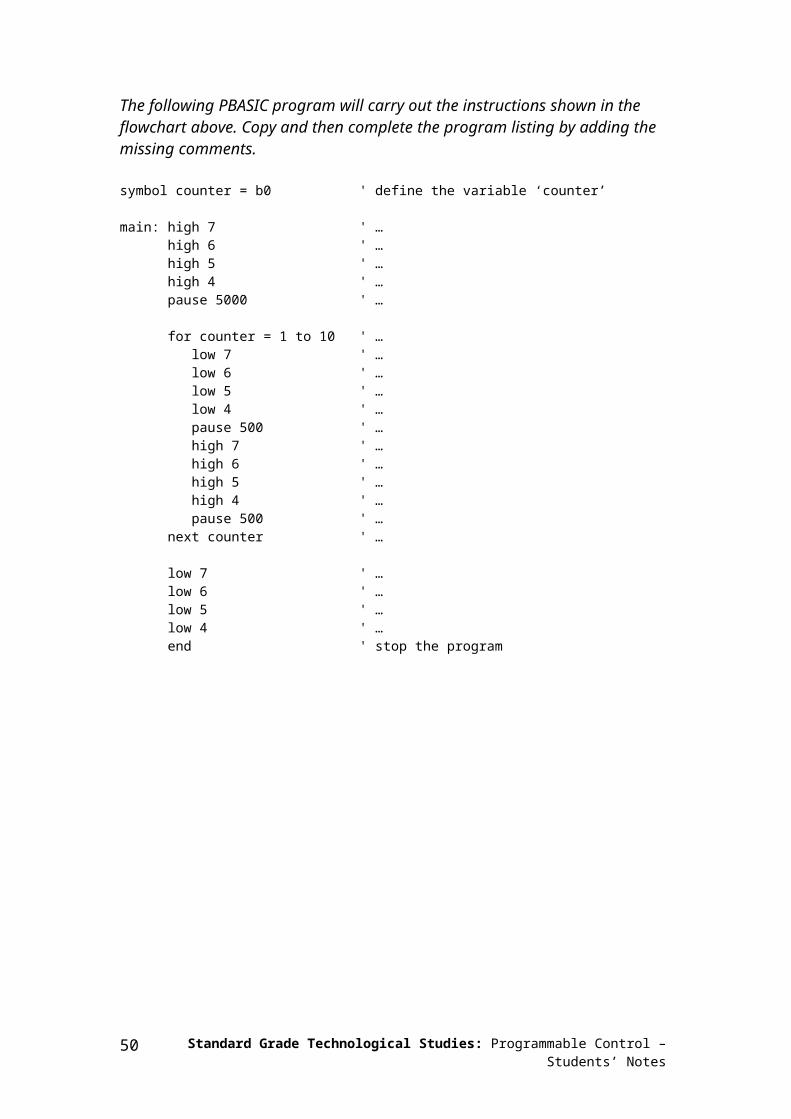
The following PBASIC program will carry out the instructions shown in the flowchart above. Copy and then complete the program listing by adding the missing comments.
symbol counter = b0 ' define the variable ‘counter’
main: high 7 ' …high 6 ' …high 5 ' …high 4 ' …pause 5000 ' …
for counter = 1 to 10 ' … low 7 ' … low 6 ' … low 5 ' … low 4 ' … pause 500 ' … high 7 ' … high 6 ' … high 5 ' … high 4 ' … pause 500 ' …next counter ' …
low 7 ' …low 6 ' …low 5 ' …low 4 ' …end ' stop the program
Standard Grade Technological Studies: Programmable Control – Students’ Notes 41

Sub-procedures
A sub-procedure is a separate ‘mini-program’ that can be called from the main program. Once the sub-procedure has been carried out, the main program continues.
Sub-procedures are often used to separate the program into small sections to make it easier to understand. Sub-procedures that complete common tasks can also be copied from program to program to save time.
The following program uses two sub-procedures to separate the two main sections of the program (‘flash’ and ‘noise’).
symbol red = 7 ' rename pin 7 ‘red’symbol buzzer = 6 ' rename pin 6 ‘buzzer’symbol counter = b0 ' define a counter using variable b0
main: ' make a label called ‘main’gosub flash ' call the sub-procedure flashgosub noise ' call the sub-procedure noisegoto main ' loop back
end ' end of the main program
flash: ' make a sub-procedure called ‘flash’for counter = 1 to 25 ' start a for … next loop high red ' red LED on pause 50 ' wait 0.05 second low red ' red LED off pause 50 ' wait 0.05 secondnext counter ' next loopreturn ' return from the sub-procedure
noise:high buzzer ' buzzer onpause 2000 ' wait 2 secondslow buzzer ' buzzer offreturn ' return from the sub-procedure
Activity 3.dKey in, download and run the above program.
The main program is very simple as it simply calls the two sub-procedures through the ‘gosub’ command. At the end of each sub-procedure a ‘return’ command is used to return the program flow back to the main program loop.
Note that at the end of the main program (but before the sub-procedures) an ‘end’ command has been added. This is a good idea as it stops the main program accidentally ‘falling’ into a sub-procedure at the end of the main program.
Standard Grade Technological Studies: Programmable Control – Students’ Notes42

Assignment 3.10
A washing machine has both wash and spin cycles. Add the missing comments to this PBASIC program, which will control the washing machine.
symbol motor = 7 ' rename pin 7 ‘motor’symbol counter = b0 ' name a counter variable
main: ' make a label called ‘main’gosub wash ' …gosub spin ' …gosub wash ' …gosub spin ' …gosub wash ' …gosub spin ' …
end ' …
wash: ' …for counter = 1 to 250 ' … high motor ' … pause 10 ' … low motor ' … pause 5 ' …next counter ' …return ' …
spin:high motor ' …pause 5000 ' …low motor ' …return ' …
Standard Grade Technological Studies: Programmable Control – Students’ Notes 43

Section 4: Using Inputs
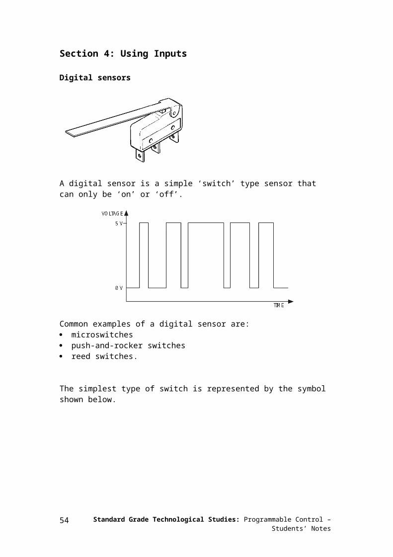
Digital sensors
A digital sensor is a simple ‘switch’ type sensor that can only be ‘on’ or ‘off’.
Common examples of a digital sensor are: microswitches push-and-rocker switches reed switches.
The simplest type of switch is represented by the symbol shown below.
Standard Grade Technological Studies: Programmable Control – Students’ Notes44

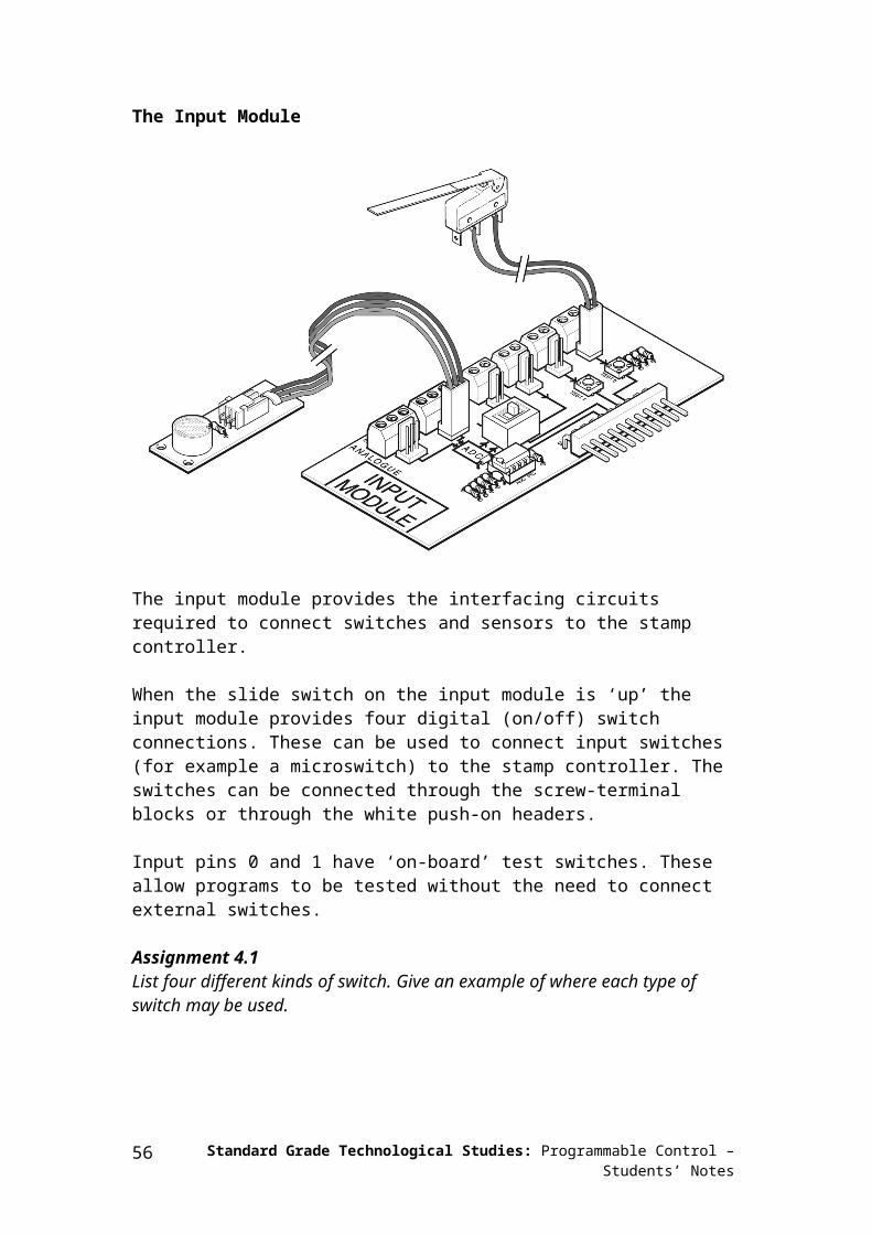
The Input Module
The input module provides the interfacing circuits required to connect switches and sensors to the stamp controller.
When the slide switch on the input module is ‘up’ the input module provides four digital (on/off) switch connections. These can be used to connect input switches (for example a microswitch) to the stamp controller. The switches can be connected through the screw-terminal blocks or through the white push-on headers.
Input pins 0 and 1 have ‘on-board’ test switches. These allow programs to be tested without the need to connect external switches.
Assignment 4.1List four different kinds of switch. Give an example of where each type of switch may be used.
Standard Grade Technological Studies: Programmable Control – Students’ Notes 45

Activity 4.aKey in, download and run the program listed below. This program makes output pin 7 flash every time the push-switch on input pin 0 is pushed.
main: ' make a label called ‘main’if pin0 =1 then flash ' jump if the input is ongoto main ' else loop back around
flash: ' make a label called ‘flash’high 7 ' switch output 7 onpause 2000 ' wait 2 secondslow 7 ' switch output 7 offgoto main ' jump back to start
In this program the first three lines make up a continuous loop. If the input is off the program just loops around time and time again.
If the switch is then pushed, the program jumps to the label called ‘flash’. The program then switches pin 7 on for two seconds before returning to the main loop.
Note carefully the spelling in the ‘if … then’ line – ‘pin0’ is all one word (without a space). Note also that only the label is placed after the command ‘then’ – no other words apart from a label are allowed.
Standard Grade Technological Studies: Programmable Control – Students’ Notes46

Assignment 4.2A burglar alarm must sound a buzzer and light a warning signal for 20 seconds when any of the four windows in a house are opened. Each window contains a reed switch that is connected to the alarm.
Draw a flowchart and write a PBASIC program that will operate the burglar alarm correctly. Use the following input and output connections.
Input connection Pin Output connection7 red light6 buzzer54
switch 3 3switch 2 2switch 1 1switch 0 0
Standard Grade Technological Studies: Programmable Control – Students’ Notes 47

Assignment 4.3As part of a Christmas decoration in a shop, a lighting sequence is to be controlled by a microcontroller. The output connections are shown below.
Input connection Pin Output connection7 red light6 yellow light5 green light4321
pressure mat 0
When a visitor treads on a pressure mat under the carpet, the lights should flash on and off in sequence three times.
The following PBASIC program will carry out the instructions shown in the table above.
Copy and then complete the program listing by adding the missing comments.
symbol counter = b0 ' …symbol red = 7 ' …symbol yellow = 6 ' …symbol green = 5 ' …
main: if pin0 = 1 then flash ' …goto main ' …
flash: for counter = 1 to 3 ' … high red ' … low green ' … pause 500 ' … high yellow ' … low red ' … pause 500 ' … high green ' … low yellow ' … pause 500 ' …next counter ' …
low green ' …goto main ' …
Standard Grade Technological Studies: Programmable Control – Students’ Notes48

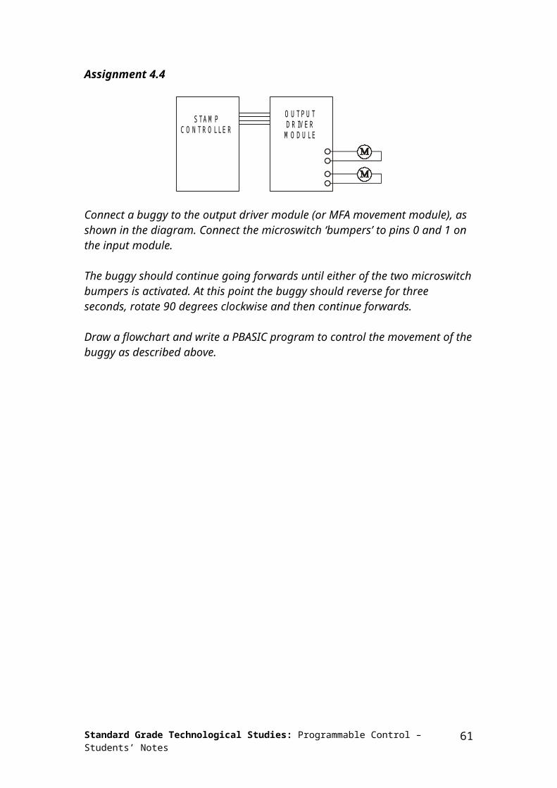
Assignment 4.4
STAM PC O NTR O LLER
O U TPU TD R IVER
M O DU LE
Connect a buggy to the output driver module (or MFA movement module), as shown in the diagram. Connect the microswitch ‘bumpers’ to pins 0 and 1 on the input module.
The buggy should continue going forwards until either of the two microswitch bumpers is activated. At this point the buggy should reverse for three seconds, rotate 90 degrees clockwise and then continue forwards.
Draw a flowchart and write a PBASIC program to control the movement of the buggy as described above.
Standard Grade Technological Studies: Programmable Control – Students’ Notes 49

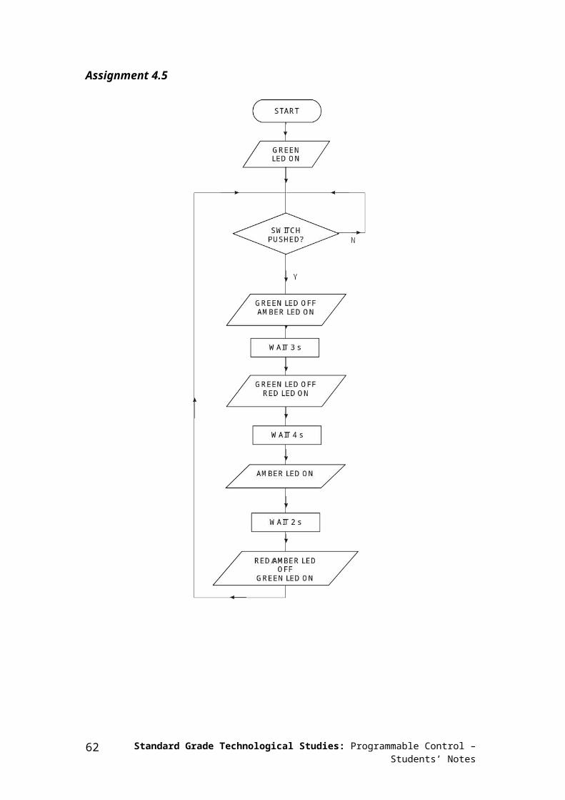
Assignment 4.5
Standard Grade Technological Studies: Programmable Control – Students’ Notes50
Develop a PBASIC program that will carry out the instructions shown in the flowchart above. Use the following pin configuration.
Input connection Pin Output connection7 red light6 amber light5 green light4321
start switch 0
Standard Grade Technological Studies: Programmable Control – Students’ Notes 51

Assignment 4.6
Connect the washing machine model to the input module and output drivers module. The washing machine model has the following connections.
Input connection Pin Output connection7 motor reverse6 motor forward5 solenoid bolt4 LED32
door microswitch 1start switch 0
The washing machine operates as follows.
1) Wait until the start switch is on.2) Wait until the door switch is on.3) Switch on the LED.4) Switch on the solenoid bolt.5) Wash cycle: repeated 20 times – motor forwards for five seconds, motor
backwards for five seconds.6) Spin cycle: repeated 10 times – motor forwards for two seconds, motor backwards
for two seconds.7) Switch off the solenoid bolt.8) Switch off the LED.
Draw a flowchart and write a PBASIC program to control the movement of the washing machine as described above.
Standard Grade Technological Studies: Programmable Control – Students’ Notes52

Assignment 4.7
Connect the bank safe model to the input module and output drivers module. The bank safe model has the following connections.
Input connection Pin Output connection7 buzzer65 solenoid/red LED4 green LED
code switch 3 3code switch 2 2code switch 1 1
door microswitch 0
Standard Grade Technological Studies: Programmable Control – Students’ Notes 53

The bank safe operates as follows.
1. Switch on the red LED.2. Switch on the solenoid bolt.3. Wait until code switch 1 is pushed.4. Wait until code switch 2 is pushed.5. Wait until code switch 3 is pushed.6. Switch off the solenoid bolt.7. Switch off the red LED.8. Wait until the door is opened (microswitch off).9. Switch on the green LED.10. Wait 10 seconds.11. Switch off the green LED.12. Switch on the buzzer.13. Wait until the door is closed (microswitch on).14. Switch off the buzzer.15. Loop back to step 1.
Draw a flowchart and write a PBASIC program to control the movement of the washing machine as described above.
Standard Grade Technological Studies: Programmable Control – Students’ Notes54
Section 5: Number Systems
A microcontroller operates by performing a large number of commands in a very short space of time. This is possible because each command can be expressed as a series of electronic signals. These electronic signals are recognised as being in one of two states, described as high and low (or ‘on’ and ‘off’).
The counting system used in everyday activities is the decimal system. This number system uses the ten familiar digits 0 to 9 to explain how big or small the number is.
However, as the microcontroller only recognises the two electronic states high and low, it uses the binary number system. This number system uses just two digits, 0 and 1. An electronic signal that is low is represented by ‘logic 0’, and a signal that is high is represented by ‘logic 1’.
The first sixteen numbers in the decimal and binary systems are shown in the table below.
Decimal Binary0 00001 00012 00103 00114 01005 01016 01107 01118 10009 100110 101011 101112 110013 110114 111015 1111
A single binary digit is referred to as a bit (binary digit). Different systems carry out calculations using different numbers of bits, and so systems are often referred to as 8-bit, 16-bit or 32-bit systems. The most common microcontrollers use the 8-bit system, although 32-bit microcontrollers are also now becoming more readily available.
Standard Grade Technological Studies: Programmable Control – Students’ Notes 55

Notation
When using a number of different counting systems it is important to distinguish which counting system you are using. For instance, the number ‘10’ has different values in the decimal and binary counting systems!
Therefore the following notations are used with stamp controller programs.
Decimal values are written as usual: 10 (= 10 in decimal)Binary values are indicated by a % symbol: %10 (= 2 in decimal)
Bits and bytes
Eight bits grouped together are described as a byte. The decimal value of a byte is calculated by adding together the corresponding decimal value of each of the individual bits. The eight bits in a byte are labelled bits 0 to 7, from right to left. The rightmost bit is called the least significant bit (LSB) and the leftmost bit is called the most significant bit (MSB). The decimal value of each bit is given in the table below.
bit number 7 6 5 4 3 2 1 0decimal value 128 64 32 16 8 4 2 1
The binary number %10010111 when converted into decimal would be:
1 x 128 = 1280 x 64 = 00 x 32 = 01 x 16 = 160 x 8 = 01 x 4 = 41 x 2 = 21 x 1 = 1
Total: 151
Note that when writing binary numbers it is quite common to write all eight bits, even if the first bits are equal to zero (unlike the decimal system, where leading zeros are not normally written).
Assignment 5.1Convert each of the following binary numbers into decimal.(a) %11110000(b) %11000011(c) %01010101(d) %10101010
Standard Grade Technological Studies: Programmable Control – Students’ Notes56
Converting decimal to binary
To convert any decimal number into binary, repeatedly divide the decimal number by two and record the remainder after each division. The binary number is then found by reading up the remainder column. The decimal number 29 is used as an example.
29 ÷ 2 = 14 rem. 114 ÷ 2 = 7 rem. 07 ÷ 2 = 3 rem. 13 ÷ 2 = 1 rem. 11 ÷ 2 = 0 rem. 1
Therefore the decimal number 29 equals the binary number %00011101
Assignment 5.2Convert each of these decimal numbers into binary.(a) 17(b) 23(c) 11(d) 38(e) 33
Standard Grade Technological Studies: Programmable Control – Students’ Notes 57

Section 6: Stepper Motors
Stepper motors are very accurate motors that are commonly used in computer disc- drives, printers, X–Y plotters and clocks. Unlike d.c. motors, which spin round freely when power is applied, stepper motors require that their power supply is continuously ‘pulsed’ in four different patterns. For each pulse, the stepper motor moves around one ‘step’, typically 7.5 degrees (giving 48 steps in a full revolution).
Stepper motors do have some limitations. First, the power consumption is greatest when the stepper motor is stopped (as all coils are still energised). The speed of revolution is also limited to around 100 steps per second, which provides a rotational speed of 2 revolutions per second or 120 revolutions per minute.
The stepper motor contains magnets that are fixed to the central armature. Four electronic coils are located around the casing. When a current is passed through these coils they generate a magnetic field, which attracts/repels the permanent magnets on the armature, and so the armature spins one ‘step’ until the magnetic fields align. The coils are then energised in a different pattern to create a different magnetic field, and the armature spins another step.
Standard Grade Technological Studies: Programmable Control – Students’ Notes58

To make the armature rotate continuously, the four coils inside the stepper motor must be switched on and off in a certain step order. The ULN2803A driver chip on the output driver module provides the method of interfacing these four coils.
The table below shows the four different steps required to make the motor turn.
Step Coil 4(output 7)
Coil 3(output 6)
Coil 2(output 5)
Coil 1(output 4)
1 1 0 1 02 1 0 0 13 0 1 0 14 0 1 1 01 1 0 1 0
To make the motor spin the other way, the steps are reversed (i.e. 4-3-2-1-4, etc. rather than 1-2-3-4-1, etc.).
NoteThe wiring configuration of stepper motors varies between different manufacturers. Therefore, it may be necessary to rearrange the coil connections for the above sequence to operate correctly. An incorrect coil arrangement will result in the stepper motor vibrating back and forth rather than rotating.
The sequence of wires for the Middlesex Stepper Motor is, from the top:white, white, blue, yellow, brown, red and you may have to change the wires on these stepper motors to get this sequence.
Standard Grade Technological Studies: Programmable Control – Students’ Notes 59

Activity 6.a
Build the circuit as shown.
Key in, download and run the program listed below. The program demonstrates how to spin the stepper motor continuously. Try changing the speed by altering the value of delay.
symbol delay = b0 ' define the variable
let delay = 100 ' set delay to 0.1s
high 7 ' set up first steplow 6high 5low 4
main: low 5 ' next stephigh 4pause delay ' pause for delay timelow 7high 6pause delay ' pause for delay timelow 4 ' next stephigh 5pause delay ' pause for delay timelow 6 ' next stephigh 7pause delay ' pause for delay timegoto main ' loop forever
Standard Grade Technological Studies: Programmable Control – Students’ Notes60

Activity 6.bA shorter way to create the same program would be to use a binary number that switches all of the output lines on and off at the same time. This means each step would then only be one program line long. The binary output number for each step is shown in the table below.
Step Binary output1 %101000002 %100100003 %010100004 %011000001 %10100000
Key in, download and run the program listed below. The ‘let pins =’ command moves the binary number on to all of the output pins in one single command. Try changing the speed by altering the value of delay.
symbol delay = b0 ' define the variable
let delay = 100 ' set delay to 0.1s
main: let pins = %10100000 ' first steppause delay ' pause for delaylet pins = %10010000 ' next steppause delay ' pause for delaylet pins = %01010000 ' next steppause delay ' pause for delaylet pins = %01100000 ' next steppause delay ' pause for delaygoto main ' loop forever
Assignment 6.1Explain the main differences between d.c. motors and stepper motors.
Assignment 6.2Describe three products that may contain stepper motors. Describe how the motor is used in each case.
Standard Grade Technological Studies: Programmable Control – Students’ Notes 61
Section 7: Analogue Sensors
An analogue sensor measures a continuous property such as light, temperature or position. The analogue sensor provides a varying voltage signal. This voltage signal can be represented by a number in the range 1 to 240 (for example very dark = 1, bright light = 240).
Common examples of a digital sensor are: LDR (light-dependent resistor) Thermistor Variable resistor (potentiometer).
Standard Grade Technological Studies: Programmable Control – Students’ Notes62
Light-dependent resistor (LDR)
The LDR is a component whose resistance depends on the amount of light falling on it. Its resistance changes with light level. In bright light the LDR’s resistance is low (typically around 1 k). In darkness its resistance is high (typically around 1 M).
The circuit symbol and a graph showing the resistance at various light levels are shown below.
The analogue sensors are connected to the input module in a potential divider arrangement.
Standard Grade Technological Studies: Programmable Control – Students’ Notes 63

Thermistor
The thermistor is a component whose resistance depends on its temperature.
The circuit symbol and a graph showing the resistance at various temperatures.
Variable resistor (potentiometer)
A variable resistor is used to measure position.
Standard Grade Technological Studies: Programmable Control – Students’ Notes64

The Input Module: Analogue Sensors
The input module provides the interfacing circuits required to connect switches and sensors to the stamp controller.
When the slide switch is ‘down’ the input module provides two digital (on/off) and two analogue sensor connections.
The two analogue sensor connections allow the connection of analogue sensors (for example an LDR light sensor or a thermistor temperature sensor). The analogue sensors provide a reading in the range of 1–240 with a change in value (of, for example, the light level or temperature).
Standard Grade Technological Studies: Programmable Control – Students’ Notes 65

Activity 7.aKey in, download and run the program listed below. This program makes a red or green LED light depending on the light level falling on an LDR sensor. Before running this program make sure you have connected a light sensor to the input module and that the slide switch is in the ‘down’ position.
main: ' make a label called ‘main’if sensorA > 50 then red ' jump if the value > 50goto green ' value is < 50 so jump
red: ' make a label called ‘red’high 4 ' switch output 4 onlow 5 ' switch output 5 offgoto main ' jump back to start
green: ' make a label called ‘green’high 5 ' switch output 5 onlow 4 ' switch output 4 offgoto main ' jump back to start
In this program the second line checks the value of sensor A. If the value is bigger than 50 the program jumps to label red.
If the value is not bigger than 50 the next ‘goto green’ line is carried out instead.
Note that only the label is placed after the command ‘then’ in the ‘if … then’ – no other words apart from a label are allowed.
Activity 7.bKey in, download and run the program listed below. This program gives the variable b0 the value of the temperature sensor (sensor A). The debug command then sends this value to the computer screen so that the temperature level can be seen.
Before running this program make sure you have connected a temperature sensor to the input module (sensor A) and that the slide switch is in the ‘down’ position and you have selected ‘Extended PBASIC’ from the options menu.
main: ' make a label called ‘main’let b0 = sensorA ' give b0 the value of the sensordebug b0 ' show the value on the computerpause 10 ' wait 0.01 secondgoto main ' jump back to start
Note that the debug command is not examinable.
Standard Grade Technological Studies: Programmable Control – Students’ Notes66

Assignment 7.1
A street lamp must turn on when the light level is below the level ‘100’ and turn off when the level is above ‘100’. The lamp is connected to output 7 and the LDR light sensor is connected to sensor A.
Draw a flowchart and write a PBASIC program that will make the street lamp work correctly.
Standard Grade Technological Studies: Programmable Control – Students’ Notes 67

Assignment 7.2State whether each of the input transducers below is an analogue or digital sensor.
(a) LDR(b) reed switch(c) microswitch(d) thermistor(e) variable resistor(f) tilt switch(g) push switch(h) rocker switch
Assignment 7.3For each of the input transducers stated in assignment 7.2 give an example of an electronic product that may use that transducer. Explain how the transducer would be used within the product.
Standard Grade Technological Studies: Programmable Control – Students’ Notes68

Section 8: Project Assignments
For the following practical project assignments students are expected to:1. identify the control task to be achieved2. select suitable input and output transducers, explaining the reason a particular
transducer was selected3. build a model of the system, correctly connecting the transducers through the
input and output driver modules4. develop a flowchart of the control sequence5. use the flowchart to develop and test a PBASIC program for the control sequence.
Project briefs
1. A woman has a very valuable jewellery collection. Design and build an alarm system that will detect when a light is shone on to the jewellery box.
2. Your car is nearly as long as your garage. Design and build a system that sounds a buzzer for a short time when the bumper of the car is close to the back wall of the garage.
3. Design and build an automatic door system to help reduce heat loss from a large department store.
4. A family with several small children finds that the fridge door is constantly left open. They require a system to warn them when the door of the fridge has been left open, but not when it is simply opened to take something out.
5. A large greenhouse needs a temperature monitoring system that includes a warning light to tell the owner when the temperature gets too high. The operator must lower the temperature and cancel the warning light within a short time or an alarm will sound.
6. Design and build a single-sweep windscreen wiper. The system should start when the operating switch is pushed, and stop again when it returns to the parked position.
7. Design and build a device to alert a cricket umpire when light is bad enough to stop play.
8. An advanced satellite television system must rotate the dish to a number of different positions. Design and build a system using a stepper motor that will move to four preset positions.
9. A system is required that sounds an alarm when someone breaks a beam of light or a fire breaks out in a house. The alarm must continue to sound until a reset switch is activated.
10. A rotary table for an automatic drilling process has to revolve clockwise for six seconds, stop for two seconds and then revolve anticlockwise for six seconds. It carries on going through this cycle indefinitely. Design and build this system.
Standard Grade Technological Studies: Programmable Control – Students’ Notes 69

11. Design and build a rotary table that will revolve once and then trigger a switch that will make the table revolve in the opposite direction until it triggers the switch again. The cycle should repeat indefinitely.
12. Design and build a machine that will revolve to face a moving light source.13. A venetian blind is required to tilt automatically when the light falling on it drops
below a predetermined level.14. Design and build a model of a goods lift for a hospital. For safety reasons the lift
should not operate if safety doors on any level remain open.15. Design and build a model of an automatic railway level crossing.16. Design and build an automatic curtain control that operates at dawn and dusk.
There should also be provision for a manual override switch.17. A small engineering company decides to automate its works. A system is required
that will pick up a metal disc using an electromagnet. It will then transport this disc along a line until it hits a switch, release it and return for another disc, thus completing the cycle. Design and build a model of this system.
18. In a busy production process a small vehicle is required to run along a track between two limit switches. The switches stop the motor for ten seconds, then reverse its direction, sending the vehicle back along the track. Design and build a model of this system.
19. A bus driver wants to know when people are getting on to the bus. Design a system that will sound a buzzer each time someone gets on.
20. A family occasionally leave their home unoccupied when they take a weekend holiday in a hotel. A system is required that will deter burglars by making their home appear occupied whilst they are away.
21. Design and build a warning light for shipping that will come on automatically at sunset and remain on until dawn. The light must flash on and off and turn through 270°.
22. Design and build a lift suitable for a two-storey warehouse. The lift will run unmanned but must not be able to operate unless a safety grill has been closed first. It should be possible to control the lift from both floors.
23. A heavy-duty industrial tumble dryer is required by a local cleaning contractor. The system should also include a fan to circulate hot air and a method to ensure that the door has been closed before the machine starts. The drum should also rotate in both directions during the process.
24. Design and build an audible levelling device suitable for indicating when a caravan is level.
25. Car theft has become a major problem. After careful consideration, design and build a possible burglar alarm for cars left unattended.
Standard Grade Technological Studies: Programmable Control – Students’ Notes70

PBASIC commands
Input/outputlow Switch an output pin off (low).high Switch an output pin on (high).sensor Reads the analogue input (A or B) and gives scaled value 1–240.
Timepause Pause for 1 to 65535 milliseconds.
Loopingfor next Create a FOR NEXT loop.
Program flowif then Test an input and jump to label.goto Jump to address label.
Subroutinesgosub Jump to sub-procedure.return Return from sub-procedure.
Miscellaneousend End the main program.debug Send variables to computer for viewing (not examinable).symbol Allocate a symbol for a variable or value.
Note that the software must be configured to ‘Extended PBASIC’ mode when using the ‘sensor’ command.
Standard Grade Technological Studies: Programmable Control – Students’ Notes 71
Standard Grade Technological Studies: Programmable Control – Students’ Notes72