programmable controller controlador programable...
TRANSCRIPT

Motors | Energy | Automation | Coatings
Programmable Controller
Controlador Programable
Controlador Programável
MVW-01 PLC2
User's GuideManual del UsuarioManual do Usuário

Manual PLC2 Board
Serie: MVW-01
Software: V1.5X
Language: English
Document Number: 10000673021 / 00
Publication Date: 11/2009

4
Summary of Revisions
The table below describes all revisions made to this manual.
Revision Description Section 00 First Edition -

5
Summary
Quick Parameter Reference,Fault Messages
I Parameters ..................................................................... 06II Error Messages ............................................................. 10
CHAPTER 1Safety Notices
1.1 Safety Notices in the Manual ........................................111.2 Safety Notices on the Product .......................................111.3 Preliminary Recommendations ..................................... 12
CHAPTER 2General Information
2.1 About this Manual ....................................................... 132.2 About the PLC2 Board ................................................ 132.3 General Characteristics of the PLC2 .......................... 14 2.3.1 Hardware .............................................................. 14 2.3.2 Software ................................................................ 14
CHAPTER 3Installation and Configuration
3.1 Installing the PLC Board on the Drive ......................... 153.2 Configuring the Jumpers ............................................. 163.3 Connectors Description ............................................... 163.4 Configuring the MVW-01 to Operate with PLC2 Board .................................................................. 21
CHAPTER 4Detailed Parameter Description
Detailed Parameter Description ......................................... 23

6
PLC - QUICK PARAMETER REFERENCE
QUICK PARAMETER REFERENCE, FAULT MESSAGES
Software: V1.5XApplication:Model:Serial Number:Responsible:Date: / / .
I. Parameters
The parameters presented hereby represent the functions provided by the PLC2 board. Besides them, the PLC2 alsomakes available a general-purpose range of parameters fromP800 to P899, which can be programmed by the user (refer to theWLPmanual).
(*) IMPORTANT: To enable the system to operate according the parameter seeting, the system must be reset after one or more parametershave been changed.
Parameter Description Adjustable Range Factory Unit Page [Type] SettingP750 PLC2 firmware version Related to the - - 23 [Read] purchased boardP751 Scan cycle in 100µs units 0 to 65535 - x100 µs 23 [Read] P752 (*) Resets the retentive markers 0=No action 0 = No action - 23 [Configuration] 1=Reset registerP753 (*) Loads factory settings, 0 to 65535 0 - 23 if =1234 [Configuration]P754 Position reference 0 to 65535 - rotations 23 (rotations) [Read]P755 Position reference 0 to 3599 - degrees / 10 23 (fraction of rotation) [Read]P756 Real position signal 0=Negative - - 24 [Read] 1=Positive P757 Real position (rotations) 0 to 65535 - rotations 24 [Read]P758 Real position (fraction of rot.) 0 to 3599 - degrees / 10 24 [Read]P759 Lag error 0 to 3599 - degrees / 10 24 [Read]P760 Proportional 0 to 200 50 - 24 position gain (Kp) [Configuration]P761 Integral position gain (Ki) 0 to 200 0 - 24 [Configuration]P762 Max. lag error 0 to 65535 1800 degrees / 10 24 [Configuration]P763 Disable user 0=Program enable 0=Program - 25 program 1=Program disable enable [Configuration]P764 (*) PLC address at netwrok 1 to 247 1 - 25 [Configuration]

7
PLC - QUICK PARAMETER REFERENCE
(*) IMPORTANT: To enable the system to operate according the parameter seeting, the system must be reset after one or more parameters have been changed.
Parameter Description Adjustable Range Factory Unit Page [Type] SettingP765 (*) Baud rate of RS232 1=1200 bps 4=9600 bps bits / second 25 [Configuration] 2=2400 bps 3=4800 bps 4=9600 bps 5=19200 bps 6=38400 bpsP766 (*) PID sample time 1 to 10000 1 x1.2 ms 25 [Configuration] P767 (*) Synchronous motor 0 to 10000 1800 rpm 25 speed [Configuration]P768 (*) Encoder 1 zero pulse 0 to 10000 1024 ppr = pulses per 26 (main) position revolution [Configuration] P769 (*) Encoder 1 zero pulse 0 to 3599 0 degrees / 10 26 (master) position [Configuration]P770 (*) CAN protocol 0=Disabled 0=Disabled - 26 [Configuration] 1=CANopen 2=DeviceNet P771 (*) CAN address 0 to 127 63 - 27 [Configuration]P772 (*) CAN baud rate 0=1 Mbit/s 0=1 Mbit/s Mbit/s or Kbit/s 27 [Configuration] 1=Reserved 2=500 Kbit/s 3=250 Kbit/s 4=125 Kbit/s 5=100 Kbit/s 6=50 Kbit/s 7=20 Kbit/s 8=10 Kbit/sP773 Bus off recovery 0=Manual 0=Manual - 28 [Configuration] 1=AutomaticP774 Action to be taken upon 0=Indicate the error 1=Cause a fatal - 28 detection of a communication 1=Cause a fatal error on the failure error on the device device [Configuration]P775 CAN status 0=Disable - - 29 [Read] 1=Reserved 2=CAN enable 3=Warning 4=Error passive 5=Bus off 6=Not poweredP776 Counter of received 0 to 65535 - - 29 telegrams [Read]P777 Counter of trasmitted 0 to 65535 - - 29 telegrams [Read]P778 Counter of detected errors 0 to 65535 - - 29 [Read]

8
PLC - QUICK PARAMETER REFERENCE
P779 Configuration status 0=Slave - - 29 CANopen 1=Master [Read]P780 CANopen communication 0=Disabled - - 30 status 1=Reserved [Read] 2=CANopen enabled 3=Node guarding enabled 4=Node guarding error P781 CANopen node status 0=Not initialized - - 30 [Read] 4=Stopped 5=Operational 127=Pre-operational P782 DeviceNet network status 0=Not powered / - - 31 [Read] Not on-line 1=On-line / Not connected 2=Link OK / On-line and Connected 3=Connection timeout 4=Critical link failure 5=Running auto-baudP783 DeviceNet master status 0=Master running - - 31 [Read] 1=Idle master P784 Number of input words 1 to 32 1 - 31 [Configuration]P785 Number of output words 1 to 32 1 - 31 [Configuration]P786 Fieldbus board status 0=Disable - - 31 [Read] 1=Inactive 2=Actine and Off-line 3=Active and On-lineP788 Operation mode for the 0=-10 to +10 V 0 - 32 Analog Output 1 (range from [Configuration] -32768 to +32767) 1=0 to 20 mA (range from 0 to 32767) 2=0 to 20 mA (range from 0 to 65535) 3=0 to 20 mA (range from -32768 to +32767) 4=4 to 20 mA (range from 0 to 32767) 5=4 to 20 mA (range from 0 to 65535) 6=4 to 20 mA (range from -32768 to +32767)
Parameter Description Adjustable Range Factory Unit Page [Type] Setting
(*) IMPORTANT: To enable the system to operate according the parameter seeting, the system must be reset after one or more parameters have been changed.
9
PLC - QUICK PARAMETER REFERENCE
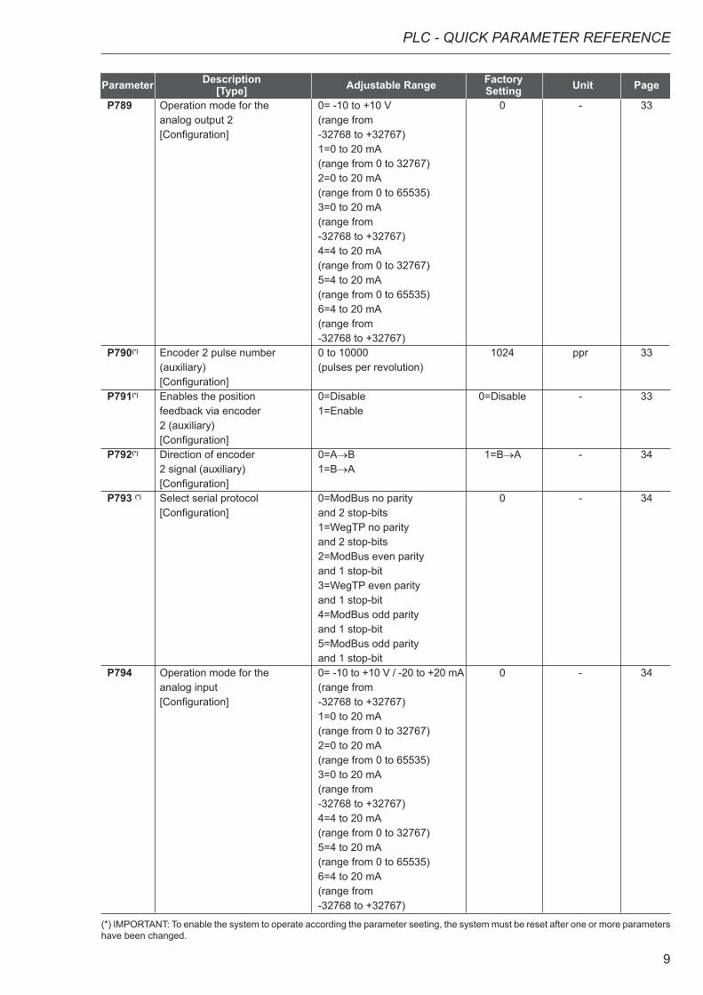
P789 Operation mode for the 0= -10 to +10 V 0 - 33 analog output 2 (range from [Configuration] -32768 to +32767) 1=0 to 20 mA (range from 0 to 32767) 2=0 to 20 mA (range from 0 to 65535) 3=0 to 20 mA (range from -32768 to +32767) 4=4 to 20 mA (range from 0 to 32767) 5=4 to 20 mA (range from 0 to 65535) 6=4 to 20 mA (range from -32768 to +32767)P790(*) Encoder 2 pulse number 0 to 10000 1024 ppr 33 (auxiliary) (pulses per revolution) [Configuration] P791(*) Enables the position 0=Disable 0=Disable - 33 feedback via encoder 1=Enable 2 (auxiliary) [Configuration] P792(*) Direction of encoder 0=A→B 1=B→A - 34 2 signal (auxiliary) 1=B→A [Configuration]P793 (*) Select serial protocol 0=ModBus no parity 0 - 34 [Configuration] and 2 stop-bits 1=WegTP no parity and 2 stop-bits 2=ModBus even parity and 1 stop-bit 3=WegTP even parity and 1 stop-bit 4=ModBus odd parity and 1 stop-bit 5=ModBus odd parity and 1 stop-bitP794 Operation mode for the 0= -10 to +10 V / -20 to +20 mA 0 - 34 analog input (range from [Configuration] -32768 to +32767) 1=0 to 20 mA (range from 0 to 32767) 2=0 to 20 mA (range from 0 to 65535) 3=0 to 20 mA (range from -32768 to +32767) 4=4 to 20 mA (range from 0 to 32767) 5=4 to 20 mA (range from 0 to 65535) 6=4 to 20 mA (range from -32768 to +32767)
Parameter Description Adjustable Range Factory Unit Page [Type] Setting
(*) IMPORTANT: To enable the system to operate according the parameter seeting, the system must be reset after one or more parameters have been changed.

10
PLC - QUICK PARAMETER REFERENCE
Display Description NoteE50 Lag error Fatal Error, it disables the converter.
Refer to Parameter P762.E51 Error during
program savingReset the systems and try again.
E52 Two or more movements enabled simultaneously
Check the user program logic.
E53 Movement data are not valid
Perhaps some speed, acceleration value, etc. was reset to zero.
E54 Inverter disabled Attempt to execute some movement with disabled inverter.
E55 Incompatible program or out of memory limits
Check program and install it again. This error also occurs when there is no program installed in the PLC (PLC powered-up first time).
E56 Wrong CRC Transmit it again. E57 Shaft has not been
referenced to absolute movement
Before an absolut movement, you must set the machine movement to zero position.
E58 Master Reference Fault Fatal Error: after enabled initial communication, between master and slave, by any cause has been disabled.
E59 Fieldbus off-line Specific error of Fieldbus communication. For further information, please, refer to the Fieldbus Communication User’s Guide included in the product CD.
E60 Board access / connection fault
Specific error of Fieldbus communication. For further information, please, refer to the Fieldbus Communication User’s Guide included in the product CD.
E61 Bus off Bus off has been detected on the CAN bus due to a high number of transfer erros. These erros may be caused due to bus problems or due to improper installation.
E63 Transceiver not powered CANopen or DeviceNet communication error. For further information, please, refer to the CANopen or DeviceNet Communication User’s Guide included in the product CD.
E65 Node Guarding Error Specific error for the CANopen communication. For further information, please, refer to the CANopen communication user’s guide provided with the product CD.
E66 Master in IDLE mode Specific error for the DeviceNet communication. For further information, please, refer to the DeviceNet communication user’s guide provided with the product CD.
E67 Timeout de conexões I/O
Specific error for the DeviceNet communication. For further information, please, refer to the DeviceNet communication user’s guide provided with the product CD.
II. Error Messages
Note: the drive is disabled with fatal errors E50 and E58 and must be reset. It is possible to use the system bit register SX2 to reset a fatal error.
11
SAFETY NOTICES
This Manual contains all necessary information for the correct installation and operation of the PLC2 with the MVW-01 Variable Frequency Drive.
The PLC2 Manual has been written for qualified personnel with suitable training of technical qualifications to operate this type of equipment.
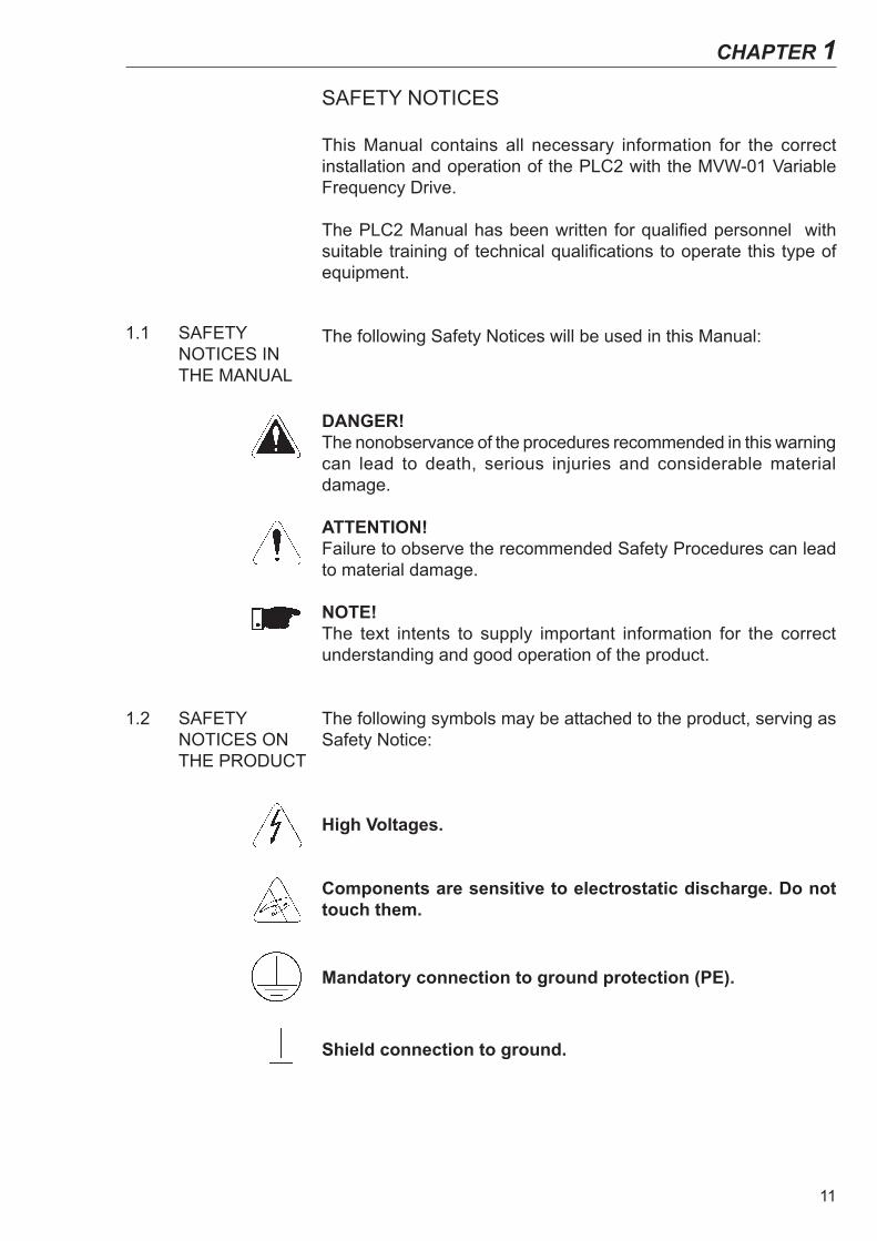
The following Safety Notices will be used in this Manual:
DANGER!The nonobservance of the procedures recommended in this warning can lead to death, serious injuries and considerable material damage.
ATTENTION!Failure to observe the recommended Safety Procedures can lead to material damage.
NOTE!The text intents to supply important information for the correct understanding and good operation of the product.
The following symbols may be attached to the product, serving as Safety Notice:
High Voltages.
Components are sensitive to electrostatic discharge. Do not touch them.
Mandatory connection to ground protection (PE).
Shield connection to ground.
1.2 SAFETY NOTICES ON THE PRODUCT
1.1 SAFETY NOTICES IN THE MANUAL
CHAPTER 1

12
CHAPTER 1 - SAFETY NOTICES
1.3 PRELIMINARY RECOMMENDATIONS
DANGER!Only qualified personnel should plan or implement the installation, start-up, operation and maintenance of the MVW-01 and associated equipment.The personnel must follow all safety instructions included in this manual and/or defined by the local regulations. Failure to comply with these instructions may result in personnel injury and/or equipment damage.
NOTE!In this Manual, qualified personnel are defined as people that are trained to: 1. Install, ground, power up and operate the MVW-01, as well as
the PLC2 board, according to this Manual and the local safety procedures;
2. Use the safety equipment according to the local regulations; 3. Give first aid.
DANGER!Always disconnect the supply voltage before touching any electrical component inside the inverter.Many components are charged with high voltages, even after the incoming AC power supply has been disconnected or switched OFF. Wait at least 10 minutes for the total discharge of the power capacitors.
ATTENTION!All electronic boards have components that are sensitive to electrostatic discharges. Never touch any of the electrical components or connectors without following proper grounding procedures. If necessary to do so, touch the properly grounded metallic frame or use a suitable ground strap.
NOTE!Read this entire Manual carefully and completely before installing or operating PLC2 board with the MVW-01.
ATTENTION!For correct use of PLC2 board it is necessary to know how to use the WLP software. Read the enclosed WLP software user’s guide completely before using the PLC2 board on the drive.

13
GENERAL INFORMATION
This chapter defines the contents and purpose of this manual.
This manual provides instructions for installation and use of the PLC2 board.
Chapter 1 - Safety Notices;Chapter 2 - General Information;Chapter 3 - Installation and Configuration;Chapter 4 - Detailed Parameter Description.
This Manual provides information required for the correct use of the PLC2. As the PLC2 is very flexible, it allows many different operation modes as described in this manual. As the PLC2 can be applied in several ways, it is impossible to describe here all application possibilities of this board. WEG does not assume any responsibility when the PLC2 is not used according to this manual.
No part of this Manual may be reproduced in any form, without written consent of WEG.
The PLC2 board adds important CLP (Programmable Logical Con-troller) functions to the MVW-01, enabling the execution of complex linkage program by using the digital board inputs and outputs as well as the digital and analog inputs and outputs of the own inverter which can be accessed by the user´s program.
Among the several available functions we can mention simple contacts and coils up to functions that uses floating point, such as sum, subtraction, multiplication, division, trigonometry, square root functions, etc.
Other important functions are the PID blocks, high-pass and low-pass filters, saturation, comparison. All these functions operate with floating point.
Besides the functions mentioned above, the PLC2 provides blocks for motor speed and motor position control, that is a trapezoidal-profile positioning and a S-profile positioning, speed reference generation with trapezoidal acceleration ramp, etc. (Note: when positioning functions used, the coupling of an encoder on motor shaft is required).
All functions can interact with the user through the 100 program-mable parameters that can be acessed directly through the inverter HMI. The texts and user units of the programmable parameters can be customized by the WLP.
2.1 ABOUT THIS MANUAL
2.2 ABOUT THE PLC2 BOARD
CHAPTER 2

14
CHAPTER 2 - GENERAL INFORMATION
2.3 GENERAL CHARACTERISTICS OF THE PLC2
2.3.1 Hardware
2.3.2 Software
ATTENTION!- The MVW-01 inverter software version should be the version V1.6X or later.
The PLC2 board has the following hardware characteristics:
9 isolated digital inputs, bi-directional, 24 Vdc;1 motor PTC input;3 digital relay output 250 V x 3 A;3 digital optocoupled outputs, bi-directional, 24 Vdc x 500 mA;1 differential analog input (-10 to +10) Vdc or (-20 to +20) mA, 14 Bits;2 analog outputs (-10 to +10) Vdc or (0 to +20) mA, 12bits;2 isolated encoder input, with external supply of 5 Vdc or 8 Vdc to 24 Vdc;1 serial communication interface -- RS-232C (standard Protocol: MODBUS-RTU);All sizes compatible with MVW-01;It permits the use of digital and analog inputs/ouputs of the MVW-01, comprising 15 digital inputs(1), 9 digital outputs(2), 3 analog inputs(3) and 4 analog outputs(4), accessed by the ladder;CANopen Master/Slave and DeviceNet Slave communication;Option for Profibus DP Slave communication;Option for DeviceNet communication.
(1) Dl1 to Dl8.(2) DO1, DO2, RL1 to RL3.(3) Al1 and Al2.(4) AO1 and AO2.
The software for the PLC2 board has the following characteristics:
The Parameter Range comprises the parameter from 750 to 899, totaling 150 parameters. The 50 first parameters are predefined by the system or are reserved parameters. The other 100 remaining parameters are for general use, i. e., they may be programmed by the user and can be used for the most different functions, as contactors, timers, speed, acceleration and position references, etc.;
Volatile (zero-initialized) and retentive BIT, WORD and FLOAT registers;
The programming of the PLC2 board is performed via WLP Software using the Ladder Logic Language, with specific blocks for positioning and CLP functions;
Memory capacity for the user program: 64 kB (65536 bytes); On-line monitoring.
ATTENTION!The PLC2 version 1.5X is compatible only with the WLP software version 6.20 or higher.

15
3.1 INSTALLING THE PLC BOARD ON THE DRIVE
INSTALLATION AND CONFIGURATION
This chapter is intended to describe the installation and configura-tion procedures for the PLC2 board.
ATTENTION!Follow the instructions included in this user’s guide to guarantee the correct installation and operation of the PLC2 board and the MVW-01 drive.
The PLC2 board is directly installed on the MVC2 control board.
Follow the steps bellow for the proper installation of the board:
Step 1 - Make sure the equipment is disconnected from the power supply and remove the frontal cover of the MVW-01.
Step 2 - Configure the jumpers of the board according to tables 3.1, 3.2 and 3.3 of the CONFIGURING THE JUMPERS section.
Step 3 - Replace the metal and plastic spacers installed on the MVC2 control board by the spacers provided with the PLC2 kit.
Step 4 - Seat the PLC board on the MVW-01 control board align-ing the terminals of the XC4 and XC5 connectors (on the PLC board) with the terminals of the female XC140 and XC3 connectors (on the MVC2 control board).
Step 5 - Check if all terminals of the XC4 and XC5 connectors are aligned.
Step 6 - Press the center and the left up corner of the board until it is completely seated on the spacers.
Step 7 - Insert and tighten the screws to firmly secure the board to the 2 metal spacers.
Step 8 - When using the PTC input of the PLC2 board, plug the cable connected to connector XC11 of the PLC2 board into connector XC11 of the drive control board (MVC2).
CHAPTER 3

16
CHAPTER 3 - INSTALLATION AND CONFIGURATION
3.3 CONNECTORS DESCRIPTION
3.2 CONFIGURING THE JUMPERS
Some functions and characteristics of the PLC board operation are defined by the setting of the jumpers on the board (see figure 3.1). The following tables describe the possible configurations for the jumpers and their functions.
XC1 Jumper: Selection of Encoder Power Supply Voltage
XC1 Status Encoder Power SupplyOpen (8 to 24) VdcClose 5 Vdc
Table 3.1 - XC1 jumper
ATTENTION!If XC1 is closed, do not supply the encoders with voltage higher than 5 Vdc. Higher voltages will damage the circuitry.
XC2 and XC6 Jumpers: Firmware Download
XC2 and XC6 Status OperationOpen Normal operationClose Firmware download
Table 3.2 - XC2 and XC6 jumpers
XC81 and XC82 Jumpers: Analog Outputs AO1 and AO2 Operation Mode
XC81 and XC82 position Analog output operation mode
1 and 2 Voltage (-10 to +10) Vdc2 and 3 Current (0 to 20) mATable 3.3 - XC81 and XC82 jumpers
Figure 3.1 shows the connectors and jumpers available on the PLC2 board.
Figure 3.1 - Detailed view of the connectors and jumpers of the PLC2 board

17
CHAPTER 3 - INSTALLATION AND CONFIGURATION
+-+-
COM DI
(*)
+-+- Load(*)
+--+(*)
The connectors and their terminals function are described below.
XC21 Connector: Relay Outputs and Digital Inputs
XC21 Connector Function Specification1 C DO1 Digital relay outputs Contact capacity:
3 A250 Vac
2 NO3 C DO24 NO5 C DO36 NO
7 COM DOReference for digital outputs DO4, DO5, and DO6
-
8 DO4 Bidirectional Opto-isolated Digital Outputs
Maximum Voltage: 48 VdcCurrent capacity: 500 mA9 DO5
10 DO6
11 COM DIReference for digital inputs DI1 to DI9
-
12 DI9 BidirectionalIsolated Digital Inputs
Input Voltage: (15 to 30 Vdc)Input Current:11 mA@24 Vdc
13 DI814 DI715 DI6
(*) External Power Supplies.
Figure 3.2 - Description of XC21 connector
XC22 Connector: 24Vdc Transistor Outputs and Digital Inputs
XC22 Connector Function Specifications
16 PTC1 Motor thermistor input Actuation: 3.9 k Release: 1.6 kMinimum resistance: 100 Ω
17 PTC2 PTC
18 GND ENC Reference for the power supply of the encoder input
-
19 + ENC Encoder inputpower supply
Controlled 5 Vdc or (8 to 24) VdcCurrent consumption: 50 mA + Encoders current
20 - AO2Analog output 2 (-10 to +10) Vdc or (0 to 20) mA
12 bits21 +22 - AO1
Analog output 1 (-10 to +10) Vdc or (0 to 20) mA12 bits23 +
24 - AI1Differential Analog Input 1
(-10 to +10) Vdc or (-20 to +20) mA 14 bits (**)25 +
26 DI1 Bidirectional, Isolated Digital Inputs
Input voltage:(15 to 30) VdcInput current:11 mA@24 Vdc
27 DI228 DI329 DI430 DI5
(*) External Power Supply.
(**) For current switch S1 to ON.
Figure 3.3 - Description of XC22 connector

18
CHAPTER 3 - INSTALLATION AND CONFIGURATION
Figure 3.4 shows the PTC connection to terminals 16 and 17 of XC22 connector, its operation under a motor temperature raise condition, and its return to the regular operation.
XC22
Inactive/SX1 = 0 Inactive/SX1 = 0
Temperature raise
Temperature Decrease
PTC resistance variation (ohms)
Inactive/SX1 = 0
Active/SX1 = 1
Active/SX1 = 1 Active/SX1 = 1
Figure 3.4 - Using PTC
XC3 Connector: Anybus-S of the HMS BoardFor the connection of the Anybus-S board, which enables the PLC to communicate in a Profibus DP or DeviceNet network.
XC7 Connector: RS-232CXC7 Connector Function Specification 1 5 Vdc 5 Vdc supply Current capacity:
50 mA2 RTS Request to send -3 GND Reference -4 RX Receives -5 GND Reference -6 TX Transmits -
Table 3.4 - Description of XC7 connector
XC11 connector: PTC Circuit power supplyWhen the PTC sensor is used, the appropriated cable must be connected from PLC2 board XC11 connector to the XC11 from the control board (MVC2).
XC17 Connector: CAN NetworkXC17 Connector Function Specification 1 V- Reference (GND) for the
CANopen power supply-
2 CANL CANL -3 SHIELD Shield -4 CANH CANH -5 V+ CANopen power supply (11 to 25) Vdc
50 mA@24 VdcTable 3.5 - Description of XC17 connector
ATTENTION!Both ends of the CAN network bus shall be terminated with a 120Ω resistor. The resistor should be connected between terminals CANL and CANH.
19
CHAPTER 3 - INSTALLATION AND CONFIGURATION
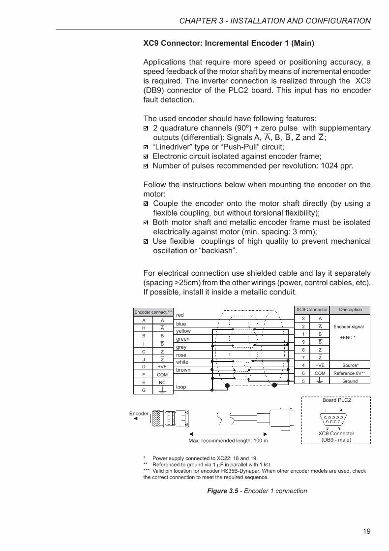
XC9 Connector: Incremental Encoder 1 (Main)
Applications that require more speed or positioning accuracy, a speed feedback of the motor shaft by means of incremental encoder is required. The inverter connection is realized through the XC9 (DB9) connector of the PLC2 board. This input has no encoder fault detection.
The used encoder should have following features: 2 quadrature channels (90º) + zero pulse with supplementary
outputs (differential): Signals A, A, B, B, Z and Z ; “Linedriver” type or “Push-Pull” circuit; Electronic circuit isolated against encoder frame; Number of pulses recommended per revolution: 1024 ppr.
Follow the instructions below when mounting the encoder on the motor:
Couple the encoder onto the motor shaft directly (by using a flexible coupling, but without torsional flexibility);
Both motor shaft and metallic encoder frame must be isolated electrically against motor (min. spacing: 3 mm);
Use flexible couplings of high quality to prevent mechanical oscillation or “backlash”.
For electrical connection use shielded cable and lay it separately (spacing >25cm) from the other wirings (power, control cables, etc). If possible, install it inside a metallic conduit.
red
blueyellowgreen
rosewhitebrown
grey
loop
Encoder
Max. recommended length: 100 m
Board PLC2
Encoder connect.***
A A
H A
B B
I B
C Z
J Z D +VE
F COM
E NC
G
XC9 Connector Description
3 A
2 A Encoder signal 1 B
9 B
8 Z
7 Z
4 +VE Source*
6 COM Reference 0V**
5 Ground
+ENC *
XC9 Connector (DB9 - male)
* Power supply connected to XC22: 18 and 19.** Referenced to ground via 1 mF in parallel with 1 kΩ.*** Valid pin location for encoder HS35B-Dynapar. When other encoder models are used, check the correct connection to meet the required sequence.
Figure 3.5 - Encoder 1 connection

20
CHAPTER 3 - INSTALLATION AND CONFIGURATION
XC10 Connector: Incremental Encoder 2 (Auxiliary)
The connection of the auxiliary encoder 2 is made through the XC10 connector (DB9) of the PLC2 board.This input can be used in applications where it is necessary to use an external encoder to perform positioning functions.However, this input shall not be used for motor speed feedback. Motor speed feedback is made through XC9 connector of the main encoder 1. This input has not encoder fault detection.
The used encoder should have following features: 2 quadrature channels (90º) + zero pulse with supplementary
outputs (differential): Signals A, A, B, B, Z and Z ; “Linedriver” type or “Push-Pull”; Electronic circuit isolated against encoder frame; Number of pulses recommended per revolution: 1024 ppr.
Use shielded cable for the electrical connection and run it away (at least 25 cm) from the other wiring (power, control cables, etc.). If possible, run the cables inside a metal conduit.
Set P791 to 1 in order to use this input as a position feedback.
XC9 Connector (DB9 - male)
+ENC *
Encoder
Max. recommended length: 100 m
Board PLC2
Encoder connect.***
A A
H A
B B
I B
C Z
J Z D +VE
F COM
E NC
G
XC10 Connector Description
3 A
2 A Encoder Signal
1 B
9 B
8 NC 7 NC 4 +VE Source*
6 COM Reference 0 V**
5 Ground
red
blueyellowgreen
whitebrown
loop
* Power supply connected to XC22: 18 and 19.** Referenced to ground via 1 mF in parallel with 1 kΩ.*** Valid pin location for encoder HS35B-Dynapar. When other encoder models are used, check the correct connection to meet the required sequence.
Figure 3.6 - Encoder 2 connection
NOTE!The maximum permitted frequency for the main/auxiliary encoder is 100 kHz.

21
CHAPTER 3 - INSTALLATION AND CONFIGURATION
3.4 CONFIGURING THE MVW-01 TO OPERATE WITH PLC2 BOARD
In order to enable the MVW-01 to be controlled by the PLC2 board it is necessary to perform the following configurations, depending on the desired functions:
Control Type (P202):
For the blocks that generate speed reference, you can use the converter in ‘Sensorless’ (P202=3) mode. Please consider that in this operation mode there is no high precision at low speed. In addition, the position gain Kp (P760) should be reset to zero to prevent instability when the motor is disabled. For the position blocks, the inverter must be operated in vector mode with encoder (P202 = 4).
Important Notes:
Always when possible, use the vector mode with encoder; The scalar mode operation (V/Hz) should be avoided if the
PLC will generate speed reference. Check the correct setting of the P161 and P162 parameters
that are the proportional speed gain and the integral speed gain, respectively. The correct setting of these parameters are very important for a good inverter performance.
Local / Remote Selection (P220):
When the PLC is used as movement generator, this option must be set to ‘Always Local’ (P220=0).
Local Reference Selection (P221):
When the PLC is used as movement generator, this option must be set to ‘PLC’ (P221=11), i. e., the speed reference will be given by the PLC board.
Local Run/Stop Selection (P224)
To enable the PLC to control the converter through the run/stop options and also enable the PLC to disable the drive, this option must be set to ‘PLC’ (P224=4).
AO1 Output Function (P251):
To enable the PLC to control the analog inverter output 1 (AO1), set P251=12. Note that P252 is the gain of the analog output 1.
AO2 Output Function (P253):
To enable the PLC to control the analog inverter output 2 (AO2), set P253=12. Note that P254 is the gain of the analog output 2.

22
CHAPTER 3 - INSTALLATION AND CONFIGURATION
Digital Inputs DI101 to DI106, P263 to P268:
There is no need of special MVW-01 programming to access the drive’s digital inputs through the PLC board.In the PLC board programming, the digital inputs of the drive (DI1 to DI6) are named DI101 to DI106, respectively.
Digital Relay Outputs DO101 to DO103, P277, P279 and P280:
These Parameters correspond to the RL1 to RL3 drive outputs. To enable the PLC to control these outputs, you must set these parameters to the function ‘PLC’, i. e. P277=27, P279=27 and P280=27.

23
DETAILED PARAMETER DESCRIPTION
This chapter describes in details all the PLC programming and read parameters. Besides these parameters, the MVW-01 parameters must also be configured in accordance with the application (refer to the MVW-01 User’s Guide for its parameter description).
CHAPTER 4
Parameter
Range[Factory Setting]
Unit Description / NoteP750Firmware versionPLC2[Read parameter]
-[ - ]-
It shows the firmware version of the PLC board.Example: version 1.00. At the parameter you can read 100.
P751Scan cycle of the user program[Read parameter]
0 to 65535[ - ]
x100 µs
It shows the duration of the user program cycle. Each unit corresponds to 100 µs.
To obtain the value of the scan cycle, divide the value of P751 by 10.Exemple: when 79 is read, this means that the program scan cycle is 79 ÷ 10 = 7.9 ms.
P752 (*) Resets the retentive markers [Configuration parameter]
0 or 1[ 0 ]
-
It reset the retentive markers, both bit type and word type.
Set the parameter to 1 (one) and restart the system. The value of this parameter returns to 0 (zero) automatically.
P753 (*) Loads factory settings, if =1234[Configuration parameter]
0 to 65535[ 0 ]
-
It loads the factory setting to the system parameters (P750 to P799).
Set this parameter to 1234 and reset the system.
P754 Position reference (rotations) [Read parameter]
0 to 65535 [ - ]
rotations
It shows the position reference in rotations. The position reference starts at zero and after the movement has been concluded, it returns to zero.
P755 Position reference (fraction of rotation) [Read parameter]
0 to 3599[ - ]
degrees/10
It shows the fraction of the revolution of the reference position in tenth of degree. The position reference starts at zero and after the movement has been concluded, it returns to zero.
(*) IMPORTANT: To enable the system to operate according the parameter seeting, the system must be reset after one or more parameters have been changed.

24
CHAPTER 4 - DETAILED PARAMETER DESCRIPTION
Parameter
Range[Factory Setting]
Unit Description / NoteP756 Real position signal [Read parameter]
0 or 1[ - ]-
Signal of the real position shown at Parameters P757 and P758. 0 = negative1 = positive
P757 Real position (rotations) [Read parameter]
0 to 65535[ - ]
rotations
It shows the real position in rotations.
P758 Real position (fraction of rotation) [Read parameter]
0 to 3599[ - ]
degrees/10
It shows the fraction of revolution of the real position in tenth of degree.
P759Lag error [Read parameter]
0 to 3599[ - ]
degrees/10
Shows lag error in degrees/10.
P760Proportional position gain (Kp) [Configuration parameter]
0 to 200[ 50 ]
-
Increase this gain to speed up the answer to a position error and decrease this gain when system vibrates or becomes unstable.
P761Integral position gain (Ki) [Configuration parameter]
0 to 200[ 0 ]
-
It has the function to reset eventual position errors. In general, this gain is zero and may cause a position overshoot, i.e. to go beyoud the desired position and return.
P762Max. lag error [Configuration parameter]
0 to 65535[ 1800 ]
degrees/10
This is the max. permitted positioning error, i. e., the max. permitted difference between reference position and the real position, in degrees. The parameter and the lag values are divided by 10. For instance 10 at P762 means that the max. following error is 1 degree. When P762=0 (default setting), the lag error will not be checked.
(*) IMPORTANT: To enable the system to operate according the parameter seeting, the system must be reset after one or more parameters have been changed.

25
CHAPTER 4 - DETAILED PARAMETER DESCRIPTION
Parameter
Range[Factory Setting]
Unit Description / NoteP763 Disables user program if=1 [Configuration parameter]
0 or 1[ 0 ]
-
When this Parameter is set to 1, it disables the user program. This setting should be used in any abnormal condition only, where the program is causing some error type, for instance, when it prevents the communication with the serial interface. In this case, disable the program and install the new corrected version and then enable it again.
P764 (*)
PLC address at network [Configuration parameter]
1 to 247[ 1 ]
-
When, for instance, the MODBUS network con-nection is used through serial interface RS-485 (inverter RS-232 / RS-485), this parameter de-fines the address at the network board.
P765 (*) Baud rate of RS-232 [Configuration parameter]
1 to 6[ 4 (= 9600 bps) ]
-
Sets the baud rate of the serial interface. The permitted settings are:
P765 Baud-Rate (bps)1 12002 24003 48004 96005 192006 38400
Table 4.1 - Baud rate of RS-232
P766 (*) PID sample time [Configuration parameter]
1 to 10000[ 1 ]
x 1.2 ms
Defines the sampling time for the PID blocks in intervals of 1.2 ms. Example: P766 = 10 means that the PID “sampling time” will be 12 ms.
P767 (*) Synchronous motor speed [Configuration parameter]
0 to 10000[ 1800 ]
rpm
Set this parameter to the driven motor synchronous speed.
In order to calculate the motor synchronous speed use the following equation:
ns = 120 x ƒ
2p
Where:ns = Synchronous speedf = Motor frequency p = Number of pole pairs of the motor
For instance, a IV pole motor / 50 Hz has a synchronous speed of 1500 rpm.
(*) IMPORTANT: To enable the system to operate according the parameter seeting, the system must be reset after one or more parameters have been changed.

26
CHAPTER 4 - DETAILED PARAMETER DESCRIPTION
Parameter
Range[Factory Setting]
Unit Description / NoteP768 (*)
Encoder 1 pulse number (main) [Configuration parameter]
0 to 10000[ 1024 ]
ppr
It shows the number of pulses per encoder revolution.
P769 (*)
Encoder 1 zero pulse position (main) [Configuration parameter]
0 to 3599[ 0 ]
degrees/10
The input value should be in tenth of degree. This value can be used to search for the machine zero and so set the zero position.
P770 (*)
CAN protocol[Configuration parameter]
0 to 2[ 0 ]
-
The setting of this parameter allows selecting the communication protocol that will be used for the CAN interface available at the PLC2 board.
P770 Description Note0 Disable CANopen and DeviceNet protocols are
disabled. Setting P770 to’0’ enables the speed synchronism via CAN, which is programmed via WLP software (FOLLOW and MSCANWEG function blocks).
1 CANopen Setting P770 to ‘1’ makes the PLC2 board operate as master or slave on the CANopen network. Additional information about how using the PLC2 board with this protocol can be found on the CANopen communication user’s guide provided with the product CD.
2 DeviceNet Setting P770 to ‘2’ makes the PLC2 board operate as a slave on the DeviceNet network. Additional information about how using the PLC2 board with this protocol can be found on the DeviceNet communication user’s guide provided with the product CD.
Table 4.2 - CAN interface available at the PLC2 board
NOTE!Change of parameter P770 is executed when the device is reset or at next power up.
(*) IMPORTANT: To enable the system to operate according the parameter seeting, the system must be reset after one or more parameters have been changed.
27
CHAPTER 4 - DETAILED PARAMETER DESCRIPTION
Parameter
Range[Factory Setting]
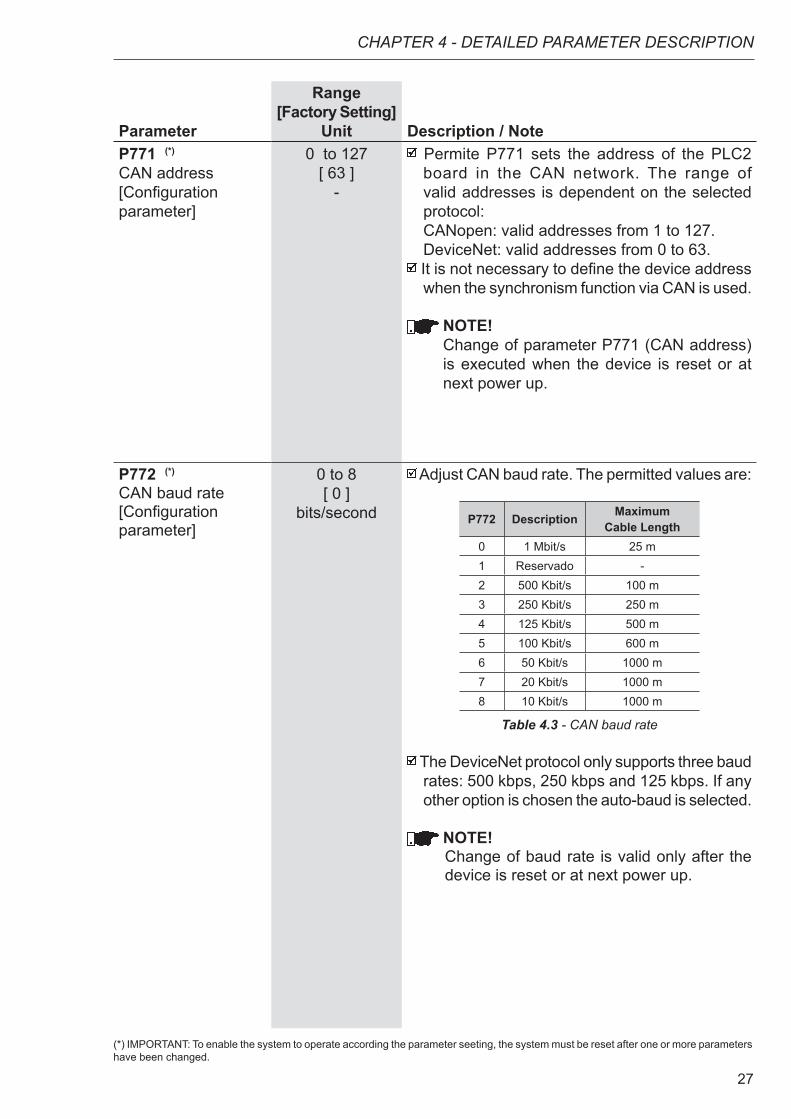
Unit Description / NoteP771 (*)
CAN address [Configuration parameter]
0 to 127[ 63 ]
-
Permite P771 sets the address of the PLC2 board in the CAN network. The range of valid addresses is dependent on the selected protocol:CANopen: valid addresses from 1 to 127.DeviceNet: valid addresses from 0 to 63.
It is not necessary to define the device address when the synchronism function via CAN is used.
NOTE!Change of parameter P771 (CAN address) is executed when the device is reset or at next power up.
P772 (*)
CAN baud rate [Configuration parameter]
0 to 8[ 0 ]
bits/second
Adjust CAN baud rate. The permitted values are:
P772 Description MaximumCable Length
0 1 Mbit/s 25 m1 Reservado -2 500 Kbit/s 100 m3 250 Kbit/s 250 m4 125 Kbit/s 500 m5 100 Kbit/s 600 m6 50 Kbit/s 1000 m7 20 Kbit/s 1000 m8 10 Kbit/s 1000 m
Table 4.3 - CAN baud rate
The DeviceNet protocol only supports three baud rates: 500 kbps, 250 kbps and 125 kbps. If any other option is chosen the auto-baud is selected.
NOTE!Change of baud rate is valid only after the device is reset or at next power up.
(*) IMPORTANT: To enable the system to operate according the parameter seeting, the system must be reset after one or more parameters have been changed.

28
CHAPTER 4 - DETAILED PARAMETER DESCRIPTION
Parameter
Range[Factory Setting]
Unit Description / NoteP773Bus off recovery[Configuration parameter]
0 or 1[ 0 ]
-
This parameter allows the PLC2 action selection when a bus off error occurs. The permitted values are:
P773 Description Note0 Manual After the bus off error has been
detected, the device displays E61, the CAN communication will be disabled and the device must be reset manually to return to network operation.
1 Automatic The communication will be restart automatically after bus off error has been detected.
Table 4.4 - Permitted values when a bus off error occurs
P774Action to be taken upon detection of a communicationfailure[Configuration parameter]
0 or 1[ 1 ]
-
Permite selecionar qual ação a PLC2 deve tomar caso ocorra erro durante a comunicação CAN:
P774 Description Note0 Indicate the
errorSetting P774 to ‘0’ displays the error code on the HMI upon detection of communication failure.
1 Cause a fatal error on the device
Setting P774 to ‘1’, besides displaying the error code on the HMI, disables the device upon detection of communication failure. Device needs to be reset in order to operate again.
Table 4.5 - Action a communication failure
Communication errors may be different according to the protocol used. Please, refer to the communication guide specific for the protocol in use.

29
CHAPTER 4 - DETAILED PARAMETER DESCRIPTION
Parameter
Range[Factory Setting]
Unit Description / NoteP775CAN status [Read parameter]
0 to 6[ - ]-
Inform CAN status:
P775 CAN Status0 Disabled1 Reserved2 CAN enabled3 Warning (some telegrams with error)4 Error Passive (Much telegrams with error or is the
only network device with enabled CAN transmitting telegrams).
5 Bus Off (number of detected errors exceeded the internal device limit and the communication has been disabled)
6 Bus not powered
Table 4.6 - CAN status
P776Counter of received telegrams [Read parameter]
0 to 65535[ - ]-
Cyclic counter is incremented at each CAN telegram received with success. Counting is restart each time the counter reaches to upper limit.
P777Counter of transmitted telegrams[Read parameter]
0 to 65535[ - ]-
Cyclic counter is incremented at each CAN telegram received with success. Counting is restart each time the counter reaches to upper limit.
P778Counter of detected errors [Read parameter]
0 to 65535[ - ]-
Cyclic counter is incremented each time an error is detected (bus off). Counting is restart each time the counter reaches to upper limit.
P779Configuration status CANopen [Read parameter]
0 or 1[ - ]-
Shows the CANopen configuration Status.0 = slave1 = master

30
CHAPTER 4 - DETAILED PARAMETER DESCRIPTION
Parameter
Range[Factory Setting]
Unit Description / NoteP780Status CANopen communication status[Read parameter]
0 to 4[ - ]-
Indicates the status of the CANopen communication, informing if the protocol was correctly initialized and the state of the slave node guarding service.
P780 Description Note0 Disabled The CANopen protocol was not set
in parameter P770 and it isdisabled.
1 Reserved -2 CANopen
enabledThe CANopen protocol wascorrectly started.
3 NodeGuardingenabled
Node guarding service was started by the master and it is properly working.
4 NodeGuarding
error
Timeout for the node guard service.This event results in a PLC board error (E65).
Table 4.7 - Status of the CANopen communication
Refer to CANopen communication user’s guide to obtain detailed description about the protocol.
P781CANopen node status [Read parameter]
0 to 127[ - ]-
Each device in the CANopen network has an associated status. The current status of the PLC2 board is displayed in this parameter.
P781 Description Note0 Not
initializedThe CANopen protocol was not setin parameter P770 and it is disabled.
4 Stopped Data transfer between master andslave is not possible in this state
5 Operational All communication services areavailable in this state.
127 Preopera-tional
Only some CANopen communication services are available in this state.
Table 4.8 - Status of the CANopen node
Refer to CANopen communication user’s guide to obtain detailed description about the protocol.

31
CHAPTER 4 - DETAILED PARAMETER DESCRIPTION
Parameter
Range[Factory Setting]
Unit Description / NoteP782DeviceNet network status [Read parameter]
0 to 5[ - ]-
P782 Description0 Not Powered / Not On-line1 On-line / Not Connected 2 On-line and Connected3 Connection Timeout4 Critical Link Failure5 Running Auto-baud
Table 4.9 - DeviceNet network status
A detailed description of these items can be found on the DeviceNet user’s guide for this product.
P783DeviceNetmaster status[Read parameter]
0 or 1[ - ]-
P783 Description0 Master in run mode1 Master in Idle mode
Table 4.10 - Estado do mestre da rede DeviceNet
For a detailed description of these items, please, refer to the DeviceNet programming user’s guide specific for this product.
P784Number of input words[Configuration parameter]
1 to 32[ 1 ]
-
The setting of this parameter defines the number of reading words exchanged with the master of the DeviceNet network.
P785 Number of output words[Configuration parameter]
1 to 32[ 1 ]
-
The setting of this parameter defines the number of writing words exchanged with the master of the DeviceNet network.
P786 Fieldbus board status [Read parameter]
0 to 3[ - ]-
Indicates the status of the optional communication board. See below the status values and their description:
P786 Description Note0 Disabled:
Indicates that the board was not enabled
The board is enabled through the WLP software, by using the tool for Fieldbus board configuration.
Table 4.11 - Status of the Fieldbus board

32
CHAPTER 4 - DETAILED PARAMETER DESCRIPTION
Parameter
Range[Factory Setting]
Unit Description / NoteP786 Description Note
1 Inactive board:Indicates that the board wasprogrammed,however, the PLC2 board could notaccess the Fieldbusboard
This situation mainly happensduring board initialization, (it can also happen during its operation), due to installation and bad connection problems. When the board is inactive, the drive shows an E60 error on the keypad, and it is only possible to enable the board again by resetting the drive.
2 Active and off-line board: indicates acommunica-tion error between theboard and the network master
This error causes the interruption of master-slave communication and may happen due to several reasons (master configuration problems, incorrect installation of communication cables, noise during data transmission, etc.).When the Fieldbus board is offline, the drive shows an E59 error on the keypad.
3 Active and on-line board: indicates that the masterslavecommuni-cation was successfully established
-
Table 4.11 - Status of the Fieldbus board (cont.)
P788 Operation mode for the analog output 1 [Configuration parameter]
0 to 6[ 0 ]
-
P788 Description0 -10 to +10 V (range from -32768 to +32767)1 0 to 20 mA (range from 0 to 32767)2 0 to 20 mA (range from 0 to 65535)3 0 to 20 mA (range from -32768 to +32767)4 4 to 20 mA (range from 0 to 32767)5 4 to 20 mA (range from 0 to 65535)6 4 to 20 mA (range from -32768 to +32767)
Table 4.12 - Operation mode for the analog output 1

33
CHAPTER 4 - DETAILED PARAMETER DESCRIPTION
Parameter
Range[Factory Setting]
Unit Description / NoteP789 Operation mode for the analog output 2 [Configuration parameter]
0 to 6[ 0 ]
-
P789 Description0 -10 to +10 V (range from -32768 to +32767)1 0 to 20 mA (range from 0 to 32767)2 0 to 20 mA (range from 0 to 65535)3 0 to 20 mA (range from -32768 to +32767)4 4 to 20 mA (range from 0 to 32767)5 4 to 20 mA (range from 0 to 65535)6 4 to 20 mA (range from -32768 to +32767)
Table 4.13 - Operation mode for the analog output 2
P790 (*)
Encoder 2 pulse number (auxiliary)[Configurationparameter]
0 to 10000[ 1024 ]
ppr
This parameter represents the number of pulses per revolution of encoder 2 (auxiliary).
P791 (*)
Enables the position feedback via encoder 2 (auxiliary)[Configuration parameter]
0 or 1[ 0 ]
-
Enables the position feedback via encoder 2 (auxiliary).
P791 Description Specification0 Disabled Encoder 1 (main encoder) is
responsible for the positionfeedback.
1 Enabled Encoder 2 (auxiliary encoder) isresponsible for the positionfeedback.
Table 4.14 - Encoder 2
(*) IMPORTANT: To enable the system to operate according the parameter seeting, the system must be reset after one or more parameters have been changed.

34
CHAPTER 4 - DETAILED PARAMETER DESCRIPTION
Parameter
Range[Factory Setting]
Unit Description / NoteP792 (*)
Direction of encoder 2 signal (auxiliary) [Configuration parameter]
0 or 1[ 1 ]
-
Defines the direction of the encoder signal:
0 = A → BDirection of encoder signals
Direction of encoder signals
B
A
Encoder running clockwise
A
B
Encoder rotating in forward direction
1 = B → A
Figure 4.1 - Direction of the encoder
P793 (*) Select serial protocol [Configuration parameter]
0 to 5[ 0 ]
-
This parameter configures the serial communi-cation: protocol, parity, and number of stop-bits, respectively.
P793 Description
0 Modbus, no parity and 2 stop-bits.1 WegTP, no parity and 2 stop-bits.2 ModBus, even parity and 1 stop-bit.3 WegTP, even parity and 1 stop-bit.4 ModBus, odd parity and 1 stop-bit.5 WegTP, odd parity and 1 stop-bit.
Table 4.15 - Select serial protocol
P794Operation mode for the analog input 1 [Configuration parameter]
0 to 6[ 0 ]
-
P794 Description0 -10 to +10 V / -20 to +20 mA
(range from -32768 to +32767)1 0 to 20 mA (range from 0 to 32767)2 0 to 20 mA (range from 0 to 65535)3 0 to 20 mA (range from -32768 to +32767)4 4 to 20 mA (range from 0 to 32767)5 4 to 20 mA (range from 0 to 65535)6 4 to 20 mA (range from -32768 to +32767)
Table 4.16 - Operation mode for the analog input
(*) IMPORTANT: To enable the system to operate according the parameter seeting, the system must be reset after one or more parameters have been changed.