programmable controller s5 11 osib - siemens · programmable controller s5 11 - osib manual order...
TRANSCRIPT
Programmable Controller S5 11 OSIB
- Manual Order No. 6ES5 998-OSA22
Issue 2
SIEMENS AKTIENGESELLSCHAFT
Contents
Operating Instructions
Programming Instructions
1 Operating lnstructions
Order No.
GWA-4NEB 807 2121 -02
GWA-4NEB 807 2122-02
Programming lnstructions
SIMATIC S5-IIOSIB Programmable Controller
Operating Instructions
SIEMENS
SlMATlC SS110 S/B Programmable Controller
Operating Instructions Order No. GWA4NEB 807 2121 -02
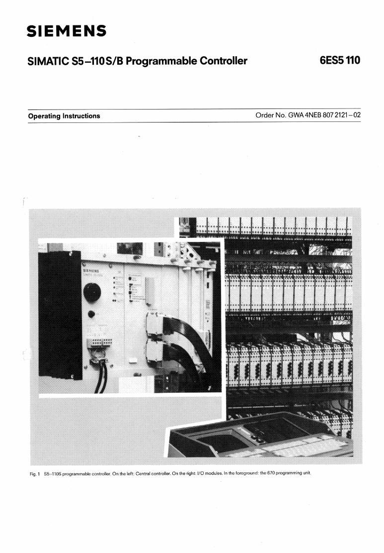
Fig. 1 S5-110s programmable controller. On the left: Central controller. On the right: 110 modules. In the foreground: the 670 programming unit
1. Description
3.1 AppficaZion 1.2 Construction
Contents Page
1. Description 2 1.1 Application 2 1.2 Co?s?ruclion 2 'i .3 Principle of operation 3 1.4 Technical specification 6 1.4.1 General data of the S5-110S PC 6 1.4.2 Power supply unit 6 1.4.3 CPUImemory submodule 7 1 .4.4 51 1 1512 interface module and 3401350 memorymodule 7 1.4.5 Digitallanalog compact 110 modules, 302 serial
l10 interface module and 210 monitor interface module 8
1.4.6 ! IQ modules (digital inputloutput modules) 8
2. Installation 2.1 Generai 2.2 Central controller 2.2.1 Power supply 2.2.2 C?Ulmemory submodule 2.2.3 Interface moduie 511 and 512C 2.2.4 3401350 memory module
3 .l Application
The 110s programmable controller (PC) is part of the SIMAilC S5 System. It is desigred for automation tasks in the middle and upper per- formance ranges. The degree of expansion and the range of functions are matched to the typical requirements in these ranges.
The PC can be easily adapted to the required tasks on account of its expandibility.
Combination with other SIMATIC programmable controllers and hard-wired controllers is possible.
1.2 Construction
The 110s is available in various basic versions and can be equipped with different power supply units (220 VAC/240VAC, 11 5 VAC or 24 V DC). The programmable controller is designed for operation without fans.
The modules are accommodated in a rugged housing, which can be mounted without difficulty in electronic cabinets and which is also suitable for wall mounting. The modules are inter- connected via the flow-soldered backplane PCB located in the rearwali of the housing. Connectors with 48 or 64 pins are used in the backplane PCB.
The programmable controller uses the familiar digital input1 output modules of the 110 A PC range. These modules are available in 24 V ACIDC, 48 V ACIDC, 115 VAC and 220 VAC versions and contain either S inputs or 8 outputs each. The modules are mounted on a separate mounting rack and con- trolled directly from the CPU.
In addition, module locations 3,4,5 or 6 of the central controller in Fig. 3 can also be osed for digitallanalog peripheral I IQ mo- dules (c~mpact versior! 20 mm wide), the 302 serial peripheral interface module and the MC210 monitor interface moduie.
2.2.5 Digital compact I10 modules 2.2.6 Analog compact l10 modules 2.2.7 302 serial I10 interface module 2.2.8 MC210 monitor interface module 2.3 Digital inputloutput modules
3. Operation 3.1 Power supply (PS) 3.2 CPU
4. Maintenance and repairs 22 4.1 .1 S5-110s fault diagnosis 22 4.1.2 Interrupt analysis 23 4.1.3 Interrupt stack 24 4.1.4 System parameters 25 4.2 Connector pin assignments in the central controiler
backplane 26 4.3 Connector pin assignments of the 110 bus 2 8
5. Spare parts
6. Maximum I10 configuration 3,
Signal input Processing Signal output
Cionc*"e irl.arn
PI,?," t.l~:fn: ??"s"r.
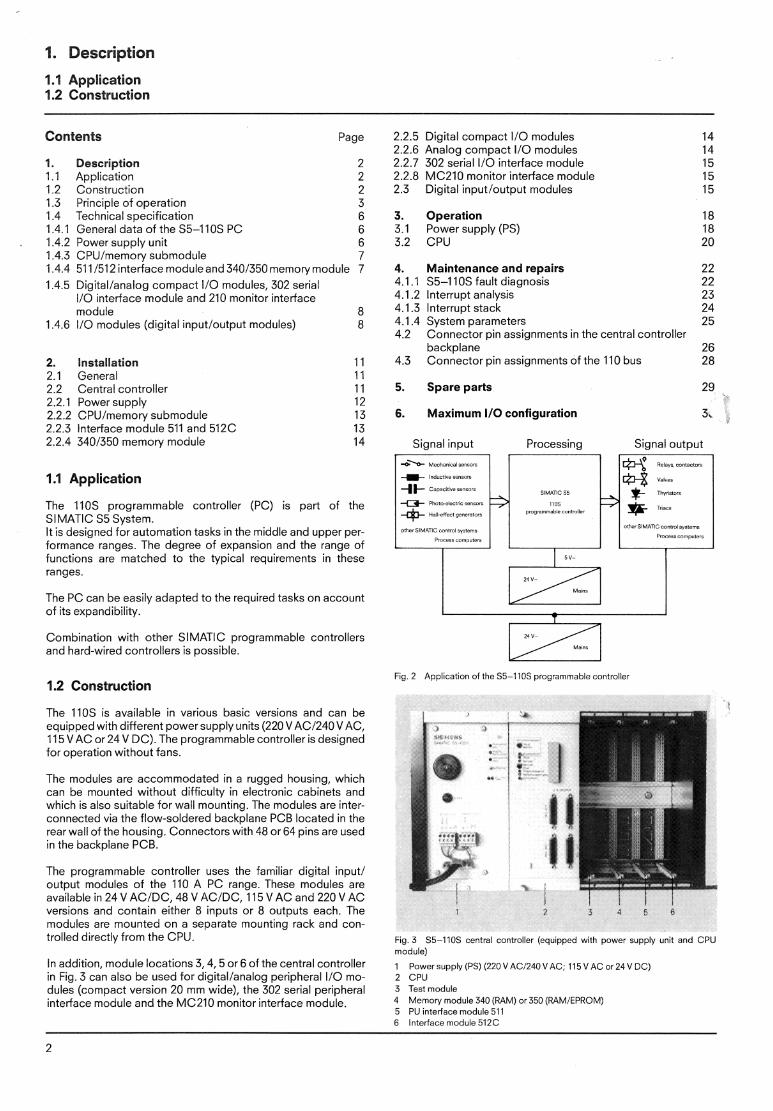
Fig. 2 Application of the 55-1105 programmable controller
Fig. 3 55-110s central controller (equipped with power supply unit and CPU module)
1 Power supply (PS) (220 V AC/240 V AC; 115 V AC or 24 V DC) 2 CPU 3 Test moduie 4 Memory module 340 (RAM) or 350 (XAMIEPROM) 5 PU interface module 51 1 6 Interface module 512C
1. Description
1.3 Principle of operation
1. Description
1.3 Principle of operation
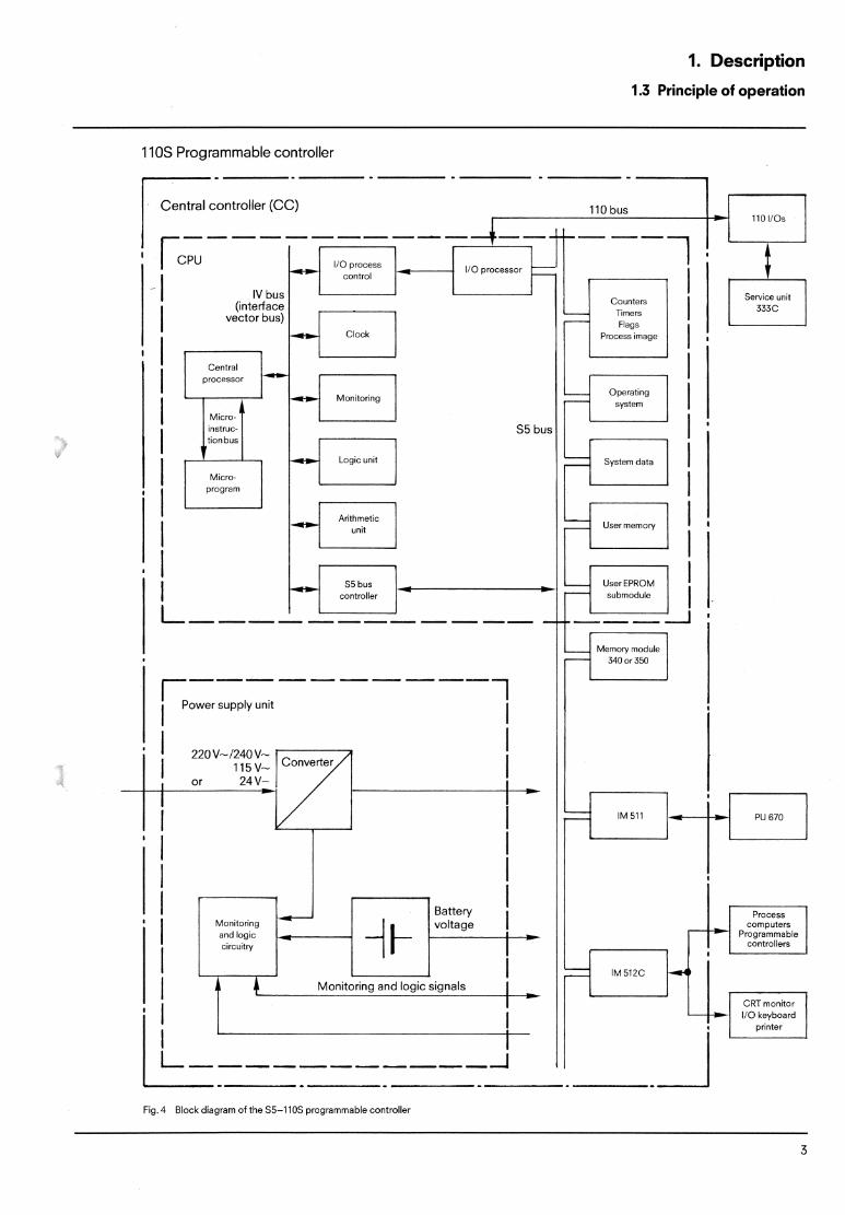
S5 bus: For exchanging data within the CPU and between the CPU and the various inter- face modules.
IV bus: Inputloutput bus of the microprocessor.
Microbus: Used forcontro!ing thecentral processor.
110 bus: Inputloutput bus connecting the 110 pro- cessor and the digital inputloutput modules.
User EPROM Contains the user program (2K, 4K or 8K module: statements, EPROM)
User memory: Contains the user program (%K state- ments, RAM)
Blocks: 128 program blocks 48 function blocks 63 data blocks (without DBO)
I10 The I10 processor scans the digital in- processor: putsloutputs and transfers the contents
to the central processor and also sets the digital outputs as required by the CPU.
CPU and Decoding and execution of the STEP 5 microprogram: statements.
Flags: 1K bits retentive, 1K bits non-retentive
Process image: Signal state of the digital inputs and out- puts stored in memory.
Timers: 128 integrated timers.
Counters: 128 integrated counters.
Monitor: Monitors faults such as acknowledge- ment delay (time-out) or cycle time ex- ceeded.
Memory module: Data expansion and extension of user 340 or 350 (with program. battery backup) RAM module 340; 8 or 16K statements
RAMIEPROM module 350; 4Kstatements (RAM) and 2 to 12K statements (EPROM)
Interface module Used for connecting up 4 external units: 512C: a) SIMATIC S5 programmable
controllers b) Terminals c) Process computers d) Keyboard printers
PU interface module For connecting the 6701675 programming 511: unit.
PU 67OCl675: The 6701675 is a very powerful video pro- gramming unit. It is used for programming and debugging all SlMATlC S5 pro- grammable controllers. The user can pro- gram in ladder diagram, control system flow-chart or statement list represen- tations.
Monitoring and logic For monitoring the external and internal in the PS: voltages.
I10 modules 110: A max. of 128 input and output modules each with 8 inputs or outputs can bd connected.
Service unit 333C: Used for testing the 110s PC. The following functions are possible: Output of data, timer and countervalues. Input of data, timer and counter values. Signal state display of inputs, outputs and flags. (The user program of the PC cannot be modified with the service unit). The service unit is connected to the PC via digital inputs and outputs.
1. Description
1.3 Principle of operation
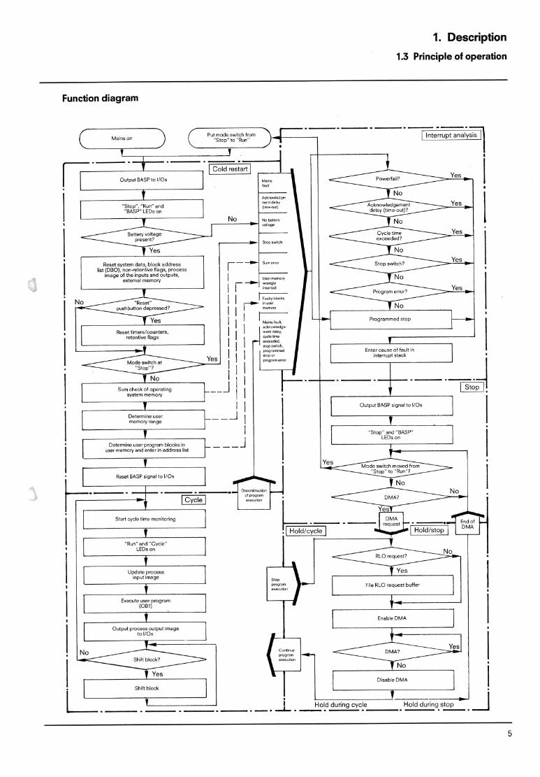
Function diagram
1. Description
1.4 Technical specification
1.4 Technical specification
1.4.1 General data of the 1105 programmable controller
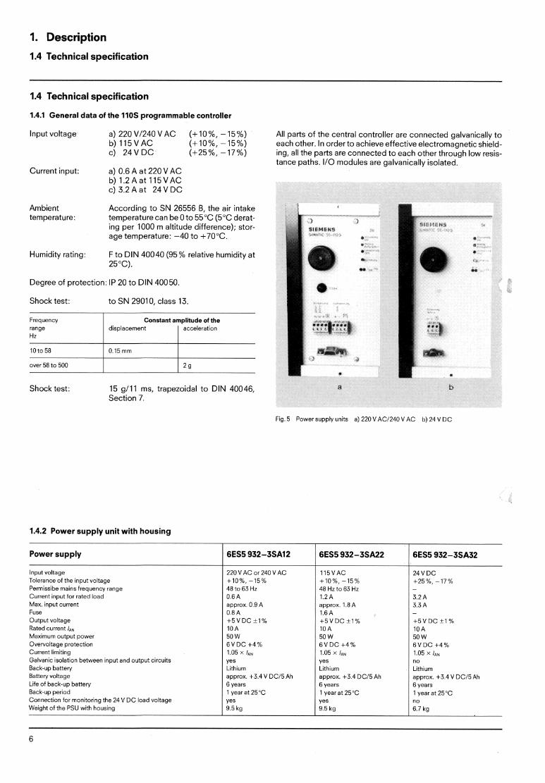
Input voltage a)220V/240VAC (+10%,-15%) All parts of the central controller are connected galvanically to b) 115VAC (+10%, -15%) each other. In order to achieve effective electromagnetic shield- c) 24V D C (+25%, -17%) ing, all the parts are connected to each other through low resis-
tance paths. I/O modules are galvanically isolated. Current input: a) 0.6 A at 220 VAC
b) 1.2Aat 115VAC c) 3.2 A at 24 V DC
Ambient According to SN 26556 B, the air intake temperature: temperature can be 0 to 55°C (5°C derat-
ing per 1000 m altitude difference); stor- age temperature: -40 to +70°C.
Humidity rating: F to DIN 40040 (95% relative humidity at 25°C).
Degree of protection: IP 20 to DIN 40050.
Shock test: to SN 29010, class 13.
over 58 to 500 l l l 2 9
Frequency range Hz
Shock test: 15 g111 ms, trapezoidal to DIN 40046, a b Section 7.
Fig 5 Power supply units a) 220VACl240 V AC b) 24 V DC
Constant amplitude of the displacement 1 acceleration
1.4.2 Power supply unit with housing
Power supply 1 6ES5932-3SA12 ! , 6ES5 932-3SA22 1 6ES5 932-3SA32
lnput voltage Tolerance of the input voltage Permissibe mains frequency range Current input for rated load Max. input current Fuse Output voltage Rated current I,,,, Maximum output power Overvoltage protection Current limiting Galvanic isolation between input and outpu: circuits Back-up battery Battery voltage Life of back-up battery Back-up period Connection for monitoring the 24 V DC load voltage Weight of the PSU with housing
220 VAC or 240 VAC +10%, -15% 48 to 63 Hz 0.6 A approx. 0.9 A 0.8 A + 5 V D C t l % 10A 50W 6 V D C + 4 % 1.05 r: yes Lithium approx +3.4 V DC15 Ah 6 years 1 year at 25°C yes 9.5 kg
115VAC +10%, -15% 48 Hz to 63 Hz 1.2A approx. 1.8 A 1.6A + 5 V D C t l % 10A 50W 6 V D C +4% 1.05 X laN
Yes Lithium approx. +3.4 DC15 Ah 6 years 1 year at 25°C yes 9.5 kg
3 2 A 3.3 A -
+ 5 V D C t 1 % 10A 50W 6 V D C + 4 % 1.05 X /AN
no Lithium approx. +3.4 V DC15 Ah 6 years l year at 25°C no 6.7 kg
"f Description
2.4 Technical specification
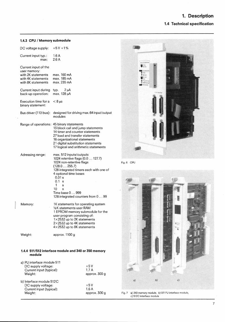
1.4.3 CPU / Memory submodule
DC voltage supply: +5 V + l %
Current input typ.: max:
Current input of the user memory: with 2K statements with 4K statements with 8K statements
Current input during back-up operation:
Execution time for a binary statement:
Bus driver (1 10 bus):
Range of operations:
max. 160 mA max. 185 mA max. 235 mA
tYP. 2 C1A max. 128 yA
designed for driving max.64 inputloutput modules
45 binary statements 13 block call and jump statements 14 timer and counter statements 27 load and transfer statements 16 organizational statements 21 digital substitution statements 17 logical and arithmetic statements
Adressing range max. 512 inputs/outputs 1024 retentive flags (0.0 127 7) 1024 non-retentive flags F I ~ 6 CPU (1 28 0 . . . 255.7) 128 integrated timers each with one of 4 optional time bases
0.01 S
0.1 S
1 S
10 S
Time base 0 . . ,999 128 integrated counters from 0 . . . 99
Memory 1 K statements for operating system %K statements user RAM 1 EPROM memory submodule for the user program consisting of. I x2532 up to 2K statements 2x2532 up to 4K statements 4x2532 up to 8K statements
Weight: approx. 1100 g
1.4.4 511/512 interface module and 340 or 350 memoly module
a) PU interface module 51 l DC supply voltage: Current input (typical): Weight:
b) Interface module 512C DC supply voltage: Current input (typical): Weight:
+ 5 v 1.7 A approx. 300 g
approx. 300 g Fig. 7 a) 340 memoy module, 5) 5 3 Pi' in!ertace module, C) 512C interface rnoduie
1. Description
1.4 Technical specification
c) Memory module 340 (RAM) 8 or 16K statements DC supply voltage: +5 V Current consumption (typ.): 0.8 or 0.9 A Current consumption in backup operation: max. 0.6 or 1 mA Approx. weight: 300 g
d) Memory module 350 (RAMIEPROM) 4K statements (RAM) and 2K to 12K statements (EPROM) DC supply voltage: +5 V Current consumption: max. 1.4 A (memory submodule 3701371 : 0.27 A each) Current consumption in backup operation: max. 0.3 mA Approx. weight: 300 g
1.4.5 Digitallanalog compact peripheral 110 modules, 302 serial peripheral interface module and 210 monitor interface module
a) Digital I10 compact modules (only 20 mm wide) Digital I10 compact modules with 16 to 32 inputsloutputs (also as niix) can be plugged into locations 3, 4, 5 or 6 in the central controller (Fig. 3). D C supply voltage: 5 V Current consumption: approx. 0.2 A Weight: approx. 200 g
b) Analog I10 compact modules Analog I10 compact modules with 4 to 16 inputloutput channels can be plugged into locations 3, 4, 5 or 6 in the central controller (Fig. 3). DC supply voltage: 5 V Current consumption: approx. 0.3 A Weight: approx. 200 g
c) 302 serial peripheral interface module The 302 interface module can be plugged into locations 3, 4, 5 or 6 in the central controller (fig. 3). However, only one expansion unit (EU182) may beconnected to each connector. D C supply voltage: 5 V Current consumption: 2 A Weight: approx. 300 g
d) 210 monitor interface moduie The 210 monitor interface module from the ESU902 pack- aging system can be plugged into location 3 in the central controller (Fig. 3). The image memory is a 2K byte RAM. DC supply voltage: +5 V Current consumption: 1.2A Weight: approx. 200 g
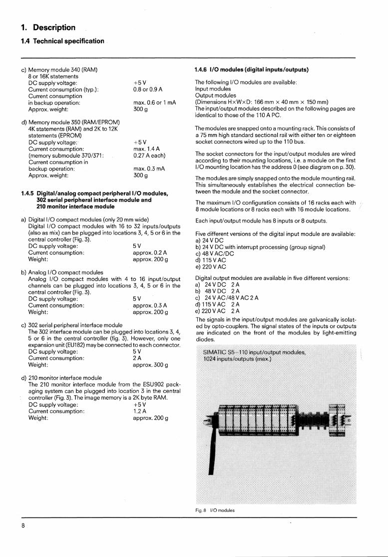
1.4.6 110 modules (digital inputs/outputs)
The following I10 modules are available: Input modules Output modules (Dimensions HxWxD: 166 mm X 40 mm X 150 mm) The inputloutput modules described on the following pages are identical to those of the 110 A PC.
The modules are snapped onto a mounting rack. This consists of a 75 mm high standard sectional rail with either ten or eighteen socket connectors wired up to the 110 bus.
The socket connectors for the inputloutput modules are wired according to their mounting locations, i.e. a moduie on the first I10 mounting location has the address 0 (see diagram on p. 30).
The modules are simply snapped onto the module mounting rail. This simultaneously establishes the electrical connection be- tween the module and the socket connector.
The maximum I10 configuration consists of 16 racks each with 8 module locations or 8 racks each with 16 module locations.
Each inputloutput module has 8 inputs or 8 outputs.
Five different versions of the digital input module are available: a) 24 V DC b) 24 V DC with interrupt processing (group signal) c) 48 V ACIDC d) 115VAC e) 220 VAC
Digital output modules are available in five different versions: a) 24VDC 2 A b) 48VDC 2 A c) 24VACl48VAC2A d ) l l 5 V A C 2 A e) 220 VAC 2 A
The signals in the inputloutput modules are galvanically isolat- ed by opto-couplers. The signal states of the inputs or outputs are indicated on the front of the modules by light-emitting diodes.
Fig. 8 I10 modules
1. Description
1.4 Technical specification
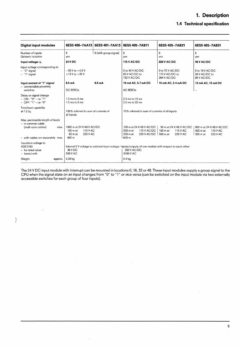
Digital input modules l 1 6ES5 400-7AA13 1 6ES5 401-7AAl3 1 6ES5 405-7ABll 1 6ES5 405-7AB21 6ES5 405-7AB11 l
Number of inputs Galvanic isolation
lnput voltage UP,
lnput voltage corresponding to - "0" signal - "l" signal
Input current at "l" signal - connectable proximity
switches
Delay on signal change ON: "O" + "1" OFF: "l" + "0"
Total load capability at 1.2 UN
Max. permissible length of leads - in common cable
(multi-core cables) max.
- with cables run separately max.
!nsulation voltage to VDE 0160 - for rated value - tested with
Weight approx.
/ 8 (with group signal) 1 iVDC 8.5 mA 8.5 mA
D C BEROs
I l 0 mA AC, 5.7 mA DC
I AC BEROs
0 to 70 V ACIDC 170 V ACIDC to 264 V ACIDC
15 mA AC, 2.4 mA DC
Oto l 8VACIDC 38 V ACIDC to 65 V ACIDC
13 mA AC, 12 mA DC
1000 m at 24 V148 V ACIDC 100mat 115VAC 50m at 220 VAC
600 m
100% referred to sum of currents of all inputs
100 m at 24 V148 V ACIDC 50 m at 24 V148 V ACIDC 800 m at 24 V148 V ACIDC 500mat 115VAC/DC lOOmat 115VAC 400mat 115VAC 250 m at 220 V ACIDC 500 m at 220 VAC 200 m at 220 VAC 600 m
75% referred to sum of currents of all inputs
Internal S V voltage to external input voltage- lnputsloutputs of one module with respect to each other 36 V D C 250 V ACIDC
500 VAC 2000 V AC
The 24V DC input module with interrupt can be mounted in locations 0,16,32 or 48.These input modules supply a group signal to the CPU when the signal state on an input changes from "0" to "1" or vice versa (can be switched on the input module via two externally accessible switches for each group of four inputs).
1. Description
1.4 Technical specification
Number of outputs Gaivanic isolation
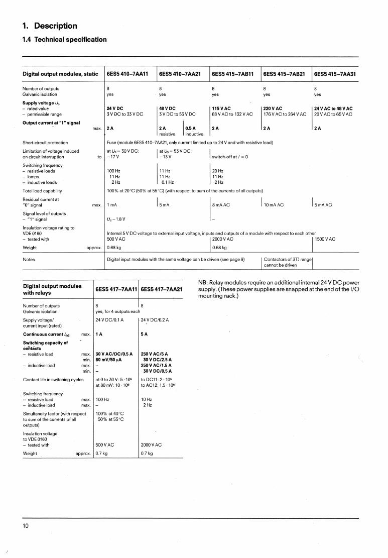
Digital output modules, static
Supply vokage Us - rated value - permissible range
Output current at "1" signal max
6ES5 410-7AA11
Short-circuit protection
Limitation of voltage induced on circuit interruption to
6ES5 410-7AA21
Switching frequency - resistive loads - lamps - inductive loads
Total load capability
6ES5 415-7ABll
Residual current at "0" signal max.
6ES5 415-7AB21
Signai level of outputs - " l " signal
6ES5 415-7M31
Insulation voltage rating to VDE 01 60 - tested with
Weight approx.
Notes
Fuse (module 6ES5 410-7AA21, only current limited up to 24 V and with resistive load)
V DC
a t u s = 30VDC: atUs=53V DC. 1 7 V 1 - 1 3 ~ / switch-off at i = 0
100% at 20'C (50% at 55'C) (with respect to sum of the currents of all outputs)
48 V DC 3 V D C t c 5 3 V D C
2 A I O S A resistive inductive
Internal 5 V DC voltage to external input voltage, inputs and outputs of a module with respect to each other 500 VAC l V A C 1 1500VAC
l l 5 V A C 220 V AC 24VACto48VAC 88VACto132VAC 176VACto264VAC 20VACto65VAC
2 A 2 1 2 1
0.68 kg
Number of outputs Galvanic ~soiat~on
0.68 kg
Output modules with relays
8 18 yes, for 4 outuuts each
Digital input moduies with the same voltage can be driven (see page 9) Contactors of 3T1 range 1 cannot be driven I NB: Relay modules require an additional internal 24 V DC power
6ES5 417-7M- supply. (These power supplies are snapped at the end of the 110 l mounting rack.)
Supply voltage1 24 V DClO.1 A current input (rated)
Continuous current l,@ max. / 1 A I 5 A Switching capacity of cefltacfs - res~stive load pax
min - inductive load max
mln
Contact life in switching cycles
Switch~ng irequency - resistive load max. - inductive load max.
Simultaneity factor (with respect to sum of the currents of all outputs)
Insulation voltage to VDE 0160 - tested with 500 VAC 2000 VAC
Weight approx. / 0.7 kg 1 0.7 kg
2. installation
2.1 General 2.2 Central controller (CC)
2.1 General
The following guidelines should be adhered to when wiring.
@ The mains cables must be kept as far away as possible from the remaining cables.
@ The M connection from the load power supply to the M,,! terminal should be made via a short connecting wire (see Fig. 11).
@ 24V lines (inputloutput modules, powersupply) and 220VAC lines (input/output modules, power supply) should be run separately or bundled separately.
0 If the 110s programmable controller is mounted inside a cabinet, the side sections and the door must have a low resistance interconnection. The cabinet must be connected to the PE conductor.
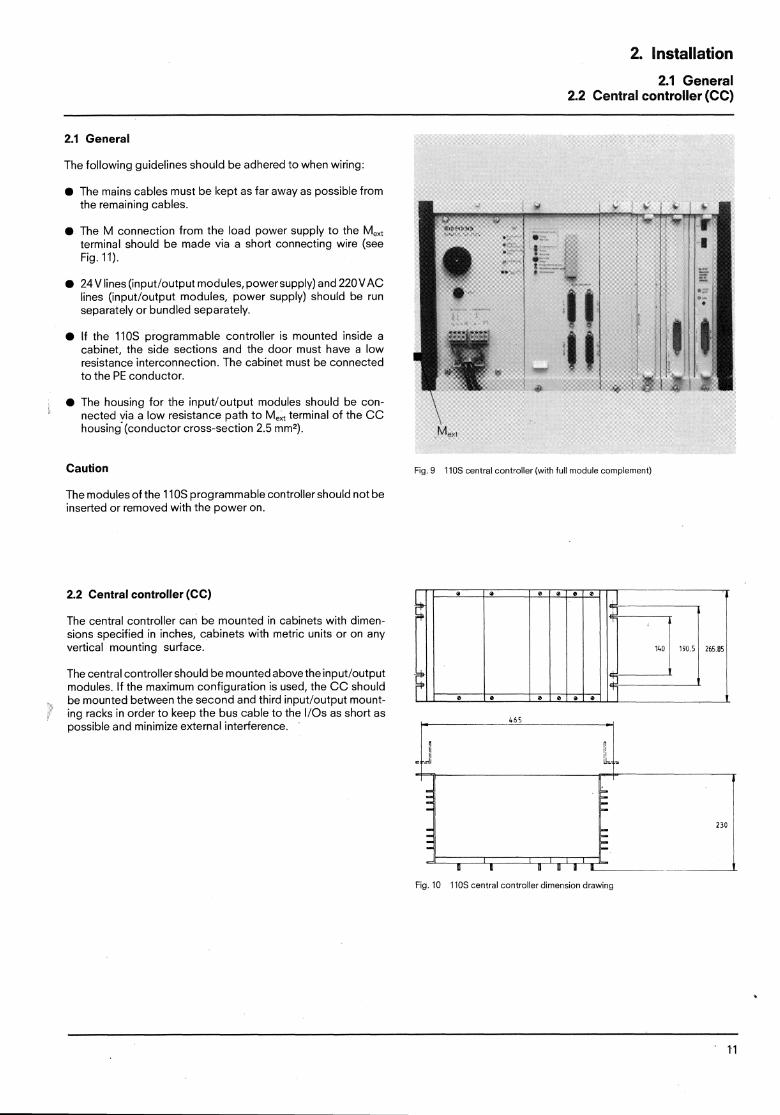
@ The housing for the inputloutput modules should be con- nected via a low resistance path to M,,, terminal of the CC \ housing (conductor cross-section 2.5 mm2). M,,,'
Caution Fig. 9 110s central controller (with full module complement)
The modulesof the 110s programmable controller should not be inserted or removed with the power on.
2.2 Central controller (CC)
The central controller can be mounted in cabinets with dimen- sions specified in inches, cabinets with metric units or on any vertical mounting surface.
The central controller should be mounted above the input/output modules. If the maximum configuration is used, the CC should be mounted between the second and third inputloutput mount- ing racks in order to keep the bus cable to the 110s as short as possible and minimize external interference.
Fig 10 110s central controller dimens~on drawing
2. Installation
2.2 Central controller
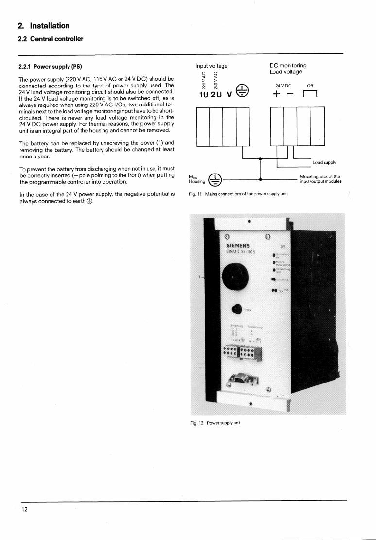
2.2.1 Power supply (PS) Input voltage D C monitoring
4: 4: Load voltage The power supply (220 VAC, 115 VAC or 24 V DC) should be > > connected according to the type of power supply used. The Ei N S N 24 V DC off 24 V load voltage monitoring circuit should also be connected. lf the 24 V load voltage monitoring is to be switched off, as is I U ~ U V O + - m always required when using 220 VAC I/Os, two additional ter- minals next to the loadvoltage monitoring input haveto be short- circuited, There is never any load voltage monitoring in the 24 V D C power supply. For thermal reasons, the power supply unit is an integral part of the housing and cannot be removed.
The battery can be replaced by unscrewing the cover (1) and removing the battery. The battery should be changed at least once a year.
To prevent the batteryfrom discharging when not in use, it must be correctly inserted (+pole pointing to the front) when putting Mounting rack of the the programmable controller into operation. input/output modules
in the case of the 24 V power supply, the negative potential is Fig. l1 Mains connections of the power supply unit
aiways connected to earth @.
Fig. 12 Power supply unit
2. Installation
2.2 Central controller
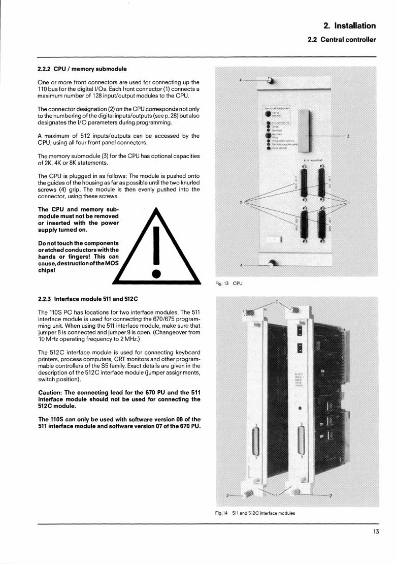
2.2.2 CPU / memory submodule
One or more front connectors are used for connecting up the 110 bus for the digital 110s. Each front connector ( l ) connects a maximum number of 128 inputloutput modules to the CPU.
The connector designation (2) on the CPU corresponds not only to the numbering of the digital inputs/outputs (see p. 28) but also designates the I10 parameters during programming.
A maximum of 522 inputsloutputs can be accessed by the CPU, using all four front panel connectors.
The memory submodule (3) for the CPU has optional capacities of 2K. 4K or 8K statements.
The CPU is plugged in as follows: The module is pushed onto the guides of the housing as far as possible until the two knurled screws (4) grip. The module is then evenly pushed into the connector, using these screws.
The CPU and memory sub- module must not be removed or inserted with the power supply turned on.
Do not touch the components or etched conductors with the hands or fingers! This can cause,destruction of the MO chips!
2.2.3 Interface module 511 and 512C
The 110s PC has locations for two interface modules. The 511 interface module is used for connecting the 6701675 program- ming unit. When using the 511 interface module, make sure that jumper 8 is connected and jumper 9 is open. (Changeover from 10 MHz operating frequency to 2 MHz.)
The 512C interface module is used for connecting keyboard printers, process computers, CRT monitors and other program- mable controllers of the S5 family. Exact details are given in the description of the 512C interface module (jumper assignments, switch position).
Caution: The connecting lead for the 670 PU and the 511 interface module should not be used for connecting the 512C module.
The 110s can only be used with software version 08 of the 511 interface module and software version 07 of the 670 PU.
Fig. l3 CPU
Fig.14 511 and 512C interface modules
2.2 Central controller
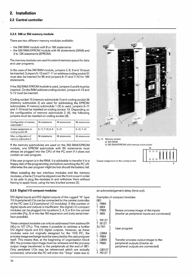
2.2.4 340 or 350 memow module
There are two different memory modules available:
- the 340 RAM module with 8 or 16K statements - the 350 RAMIEPROM module with 4K statements (RAM) and
2 to 12K statements (EPROM)
The memory modules are used to extend memoryspacefor data and user programs.
In the case of the 340 RAM module, jumpers 2,6,9 and 10 must be inserted.1umpers 5-12 and 7-1 1 on addresscoding socket 51 must also be inserted for 8K and jumpers 6-1 1 and 7-10 for 16K statements.
If the 350 RAMIEPROM module is used, jumpers 3 and 6 must be inserted. On the RAM address coding socket, jumpers 4-13 and 5-12 must be inserted.
Coding socket 19 (memory submodule 1) and coding socket 26 (memory submodule 2) are used for addressing the EPROM submodules. If memory submodule 1 (3) is used, jumpers 6 1 1 and 7-10 must be inserted on coding socket 19. Depending on the configuration of memory submodule 2 (4), the following jumpers must be inserted on coding socket 26:
Configuration of memory 21< statements 4K statements 8K statements submoduie 1 I lumper assignment on 6-11,7-10,8-9 / 5-12 coding socket 26 I Max, configuration of 8K statements 8K statements 4K statements memory submodule 2
If the memory submodules are used on the 350 RAMIEPROM module, one EPROM submodule with 8K statements must always be plugged into the CPU of the PC even if it does not contain an user program.
If the user program is in the RAM, it is advisable to transfer it to a floppy diskof the programming unit before switching the PC off, otherwise the user program might be lost should the battery fail.
When installing the two interface modules and the memory modules, a frame (1) must be slipped over the front cover in order to be able to plug the modules in and withdraw them without having to apply force, using the two knurled screws (2).
2.2.5 Digital I10 cornpact modules
512 digital inputs and 512 digital outputs of the rugged " A type 110A peripheral 110s can be connected to the central controller of the PC (see 2.2.9 peripheral 110 modules). If this number of digital inputs and outputs is insufficient, the digital l10 compact modules can be plugged into locations 3,4, 5 or 6 in the central controller (Fig. 3) or into the 182 expansion unit (only serial inter- face possible).
These compact modules caq only be addressed from address 64 (40H) to 127 (7FH). This makes it possible to address a further 512 digital inputs and 512 digital outputs. However, as these modules were not originally designed for the 1105 PC, the process image exchange must be executed by the user program itself. This means that, at the beginning of orgaqisation block OBI, the process input image must be renewed and the process output image transferred to the peripherals at the end of OBI. Only peripheral 110s may be referenced which are actually connected, otherwise the PC will enter the "Stop" state due to
Fig. 15 Memory module a) 340 (RAM) b) 350 (RAMIEPROM) with memory submoduies
16 9
lumper assignment on the cosiqg socket 1 8
an acknowledgement delay (time-out)
Examples of compact modules OB 1 L PB64 T IB64 L PB65 Renew process image of the inputs T l865 (insofar as peripheral inputs are connected)
User program
Transfer process output image to the peripheral outputs (insofar as peripheral outputs are connected)

2. Installation
2.2 Central controller 2.3 Input and output modules
2.2.6 Analog 1/0 compact modules
Analog l10 compact modules can only be plugged into the central controller (locations 3, 4, 5 or 6, Fig. 3) or into a 182 expansion unit (only serial interface possible).
Like the digital I10 compact modules, the analog 110 compact modules can only be addressed from address 64 (40H) to 127 (7FH). See the operating instructions for "Analog I10 modules (compact version)" for notes on jumpering and modification of input range.
2.2.7 302 serial peripheral interface module
The 302 serial peripheral interface module can be plugged into the locations 3, 4, 5 or 6 of the central controller (Fig. 3). This interface makes it possible to address three 182 expansion units or three 110s racks via a 311 interface module. Each 182 ex- pansion unit with a 311 interface module can be further expanded with the 300 and 312 interface modules. It must be ensured that the analog modules are plugged into the 182 expansion unit containing the 311 interface module, whereas digital modules can be plugged into any parallel expansion unit. The 110s racks with the 311 interface module can be extended with further 110s racks.
Addressing on the 302 interface module for digitallanalog peripheral 110s starts at address 64 (40H) and can go as far as address 127 (7FH) (see 2.2.5, 2.2.6). For further details, see the operating instructions "Serial interface between central controller and expansion unit".
2.2.8 MC210 monitor interface module
The 210 monitor interface module can be plugged into location 3 in the central controller (Fig. 3). This interface module makes it possible to operate a monochrome monitor with BAS input (BNC socket) via a 75 L? coaxial cable. The image format of the monitor can consist of 16 or 32 lines per image and of 32 or 64 characters per line.
The image memory of the monitor interface has a capacity of 2K bytes RAM. The starting address of the image memory must be set to the address 2K (0800~), 4K (lOOOH) or 6K (1800~) for the 110s PC. The interface module must be assigned parameters in orderto be able to be addressed by the CPU. These parameters take up 16 addresses in the peripheral address area and must be situated between peripheral adresses 64 (4OF) and 127 (7FH) in the case of the 110s PC.
For further information, see the operating instructions "Monitor interface module for the 210 micro-computer system".
Note: When using the compact modules, the plastic snap-in holders at the back of the rack must be removed.
2.3 Digital inputloutput modules
The mounting rack forthe inputloutput modulescan beattached to mounting plates or any other vertical mounting surface or mounted in cabinets with dimensions in inches or metric units.
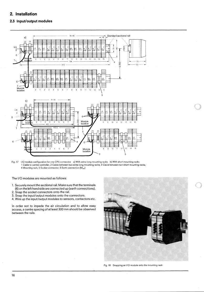
Fig. 17 shows the configuration (32 module locations) of the 110 modules for one connector in the CPU. The modules are loca- tion-coded, Identical modules must not be plugged into loca- tions with the same address, i.e. if an input module is plugged into the location with the address 0, only on output module way be plugged in under the same address (see Fig. 17). The maxi- mum I10 configuration consists of eight extra-long mounting racks or 16 short mounting racks (corresponding in both cases to 128 module locations for the inputloutput modules).
a) with dimensions in inches b) with metric dimensions (e.g. 8MF cabinets)
Fig. 16 lnstal!ation in cabinets
The length of the mounting rack is determined by the space available. If wide cabinets are used (Fig. 16), two mounting racks each with eight module locations (Fig. 17b) can be replaced by one mounting r a c ~ with 16 module locations (Fig. 17a).
In this case, the addressing is not changed and one less cable connector (3) is required. The complete addressing for the maximum configuration is shown in a diagram in the appendix (Page 30).
2. Installation
2.3 Input/output modules
P lfix40 -, 40 - -1 Standard sect~onal rail a) I
lvlooule location 1 1 1 ~ 3 4 5 5 i a ~ i o 1 1 1 ~ 1 3
Fig. 17 110 module configuration for one CPU connector a) With extra-long mounting racks b) With short mounting racks 1 Cable to central controller, 2 Cable between two extb-long mounting racks, 3 Cable between two short mounting racks 4 Mounting rack, 5 Socket connector, 6 Earth connection (M,,,)
The I10 modules are mounted as follows:
1. Securely mount the sectional rail. Make sure that the terminals (6) on the left hand side are connected up (earth connections).
2. Snap the socket connectors onto the rail. 3. Snap the inputloutput modules on.to the connectors. 4. Wire up the inputloutput modules to sensors, contactors etc.
In order not to impede the air circulation and to allow easy access, a centre spacing of at least 300 mm should be observed between the rails.
Fig. 18 Snapping an 110 module onto the mounting rack

3. Operation
3.1 Power supply (PS)
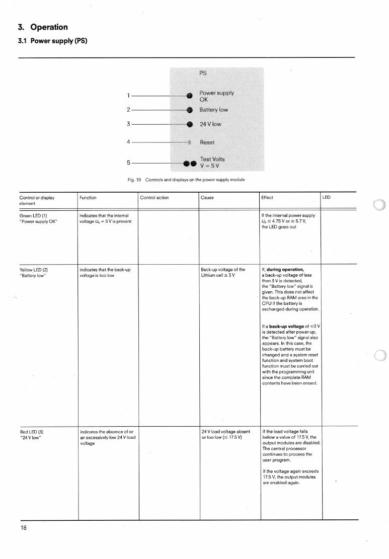
l Power sarg~ply CJK
Control or display element
Green LED (1) "Power supply O K
Yellow LED (2) "Battetv iow"
Red LED (3) "24 V low"
2 ---a Battery low
3 -* 2 4 V low
5 Test Volts v.=5v
Fig. 19 Controls and displays on the power suppiy module
exchanged during operation.
If a back-up voltage of 5 3 V is detected after power-up, the "Battery low" signal also appears. In this case, the back-up battery must be changed and a system reset , function and system boot function must be carried out with the programming unit since the complete RAM contents have been erased.
indicates the absence of or an excessively low 24 V load voitage
If the voltage again exceeds 17.5 V, the output modules are enabied again.
3. Operation
3.1 Power supply (PS)
Control or d~splay Funct~on I Control actton Cause Eiiect LED element
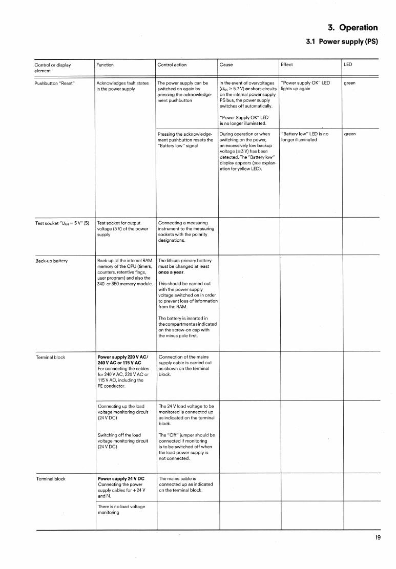
Pushbutton "Reset" Acknowledges fault states in the power supply
Test socket "UAN = 5 V" (5)
Back-up battery
Terminal block
Test socket for output voitage (5V) of the power
SUPPIS
Back-LP o i the internal RAM memory of the CPU (timers, counters, retentive flags, user program) and also the 340 or 350 memory module
The power supply can be In the event of overvoltages switched on again by (UAN > 5.7 V) or shoTt-circuits pressing the acknow!edge- i on the internal power supply ment pushbutton PS bus, the power supply
switches o f i automatically.
Pressing the acknowledge- ment pushbutton resets the "Battery low" signal
Connecting a measuring instrument to the measuring sockets with the polarity designations.
The lithium primary battery must be changed at least once a year.
This should be carried out with the power supply voltage switched on in order to preven: loss of informatior irom the RAM.
The battery is inserted in thecompartmentasindicated on the screw-on cap with the minus pole iirst
Power supply 220 VAC/ 240VAC or 115VAC For connecting the cables for 240 VAC, 220 VAC or 115 VAC, including the PE conductor.
Connection of the mains supply cable is carried out as shown on the terminal block.
"Power Supply OK" LED IS no longer iiluminated.
"Power supply OK" LED green l~ghts up again
During operation or when switching on the power, an excessively low backup voltage ( 5 3 V) has been detected.The "Battery low" display appears (see explan- ation ior yellow LED).
Connecting up the ioad voltage monitoring circuit (24 V DC)
Switching off the load voltage monitoring circuit (24 V DC)
Terminal block Power supply 24 V DC Connecting the power supply cables ior +24 V and N.
The 24 V load voltage to be monitored is connected up as indicated on the terminal block.
The "Oii" jumper should be connected if monitoring is to be switched off when the load power supply is not connected.
l
The mains cable is connected up as indicated on the terminal block.
l
3. Operation
3.2 CPU
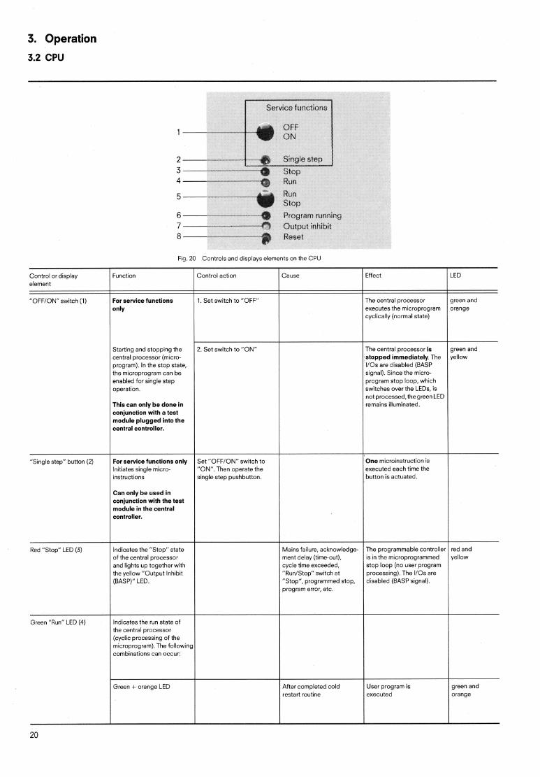
2---- - "
3- -.W-- * Stop 4 -h$& Run
6 Prngrarrr tunning 7 8 --W- ---3 Reset
Fig. 20 Controls and displays elements on tne CPU
Control or display element
"OFFION" switch (1)
Function
For service functions only
Starting and stopping the central processor (micro- program). In the stop state, the microprogram can be enabled for single step operation
This can only be done in conjunction with a test module plugged into the central controller.
Control action Cause Effect l lED
1. Set switch to "OFF" The central processor green and executes the microprogram orange cyclically (normal state)
2. Set switch to "ON" The central processor is stopped immediately. The 110s are disabled (BASP signal). Since the micro- program stop loop, which switches over the LEDs, is not processed, thegreen LED remains illuminated.
green and yellow
"Single step" button (2)
Red "Stop" LED (3)
For service functions only Initiates single micro- instructions
Can only be used in conjunction with the test module in the central controller.
lndicates the "Stop" state of the central processor and lights up together wit? the yellow "Output Inhibit (BASP)" LED.
Set "OFFION" switch to "ON". Then operate the single step pushbutton.
Mains failure, acknowledge- ment delay (time-out), cycle time exceeded, "RunIStop" switch at "Stop", programmed stop, program error, etc.
One microinstruction is executed each time the button is actuated.
The programmable controller is in the microprogrammed stop loop (no user program processing). The 110s are disabled (BASP signal).
I i
red and yellow
Green "Run" LED ( I ) Indicates the run state of the central processor (cyclic processing of the microprogram).The followir combinations can occur:
Green + orange LED green and orange
After completed cold restart routine
User program is executed
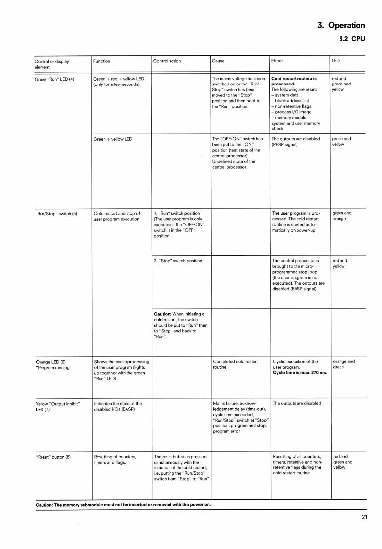
3. Operation
3.2 CPU
been put to ?he "ON" position (test state of the central processor). Undefined state of the central processor.
rogrammed stop loop he user program is not
executed). The outputs are disabled (BASP signal).
Caution: When initiating a cold restart, the switch should be put to "Run" then
user program. Cycle time is max.270 ms.
Mains failure, acknow- The outputs are disabled ledgement delay (time-out), cycle time exceeded, "RuniStop" switch at "Stop" position, programmed stop, program error
initiation of the co!d restart, i.e. putting the "RunIStop" cold restart routine. switch from "Stop" to "Run"
Caution: The memory submodule must not be inserted or removed with the power on.
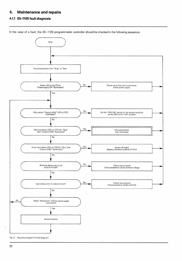
4. Maintenance and repairs
4.1.1 S5-110s fault diagnosis
In the case of a fault, the S5-110s programmable controller should be checked in the following sequence.
I Put control switch from "Stop" to "Run" I
Green LED on the PS for "Power supply OK" illuminated?
Check mains fuse and connections, check power supply I--@
Yes
Only yellow "Output ~nh~bi t " LED on CPU illumina:ed?
l
Red and yellow LEDs on CPU forZ'Stop" Yes
and "Output inhibit" illuminated7
"Output inhibit" illuminated? Replace interface modules 511:512
Yellow "Battery low" LED on power supply illuminated?
Replace battery
Fig. 21 Sequence d~agram for fault diagnosis
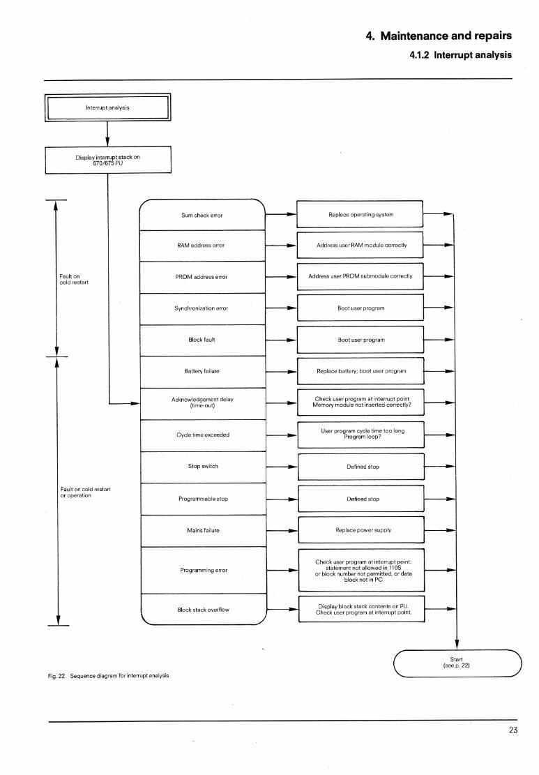
4. Maintenance and repairs
4.1.2 Interrupt analysis
I Diswiay interrupt stack on 6701675 PL' I
RAM address error
PROM address error
Synchronization error
Block fault
Cycle time exceeded
Programmable stop
Mains {allure
Programming error
Block stack overflow
I
Fig. 22 Sequence diagram for interrupt analysis
4. Maintenance and repairs
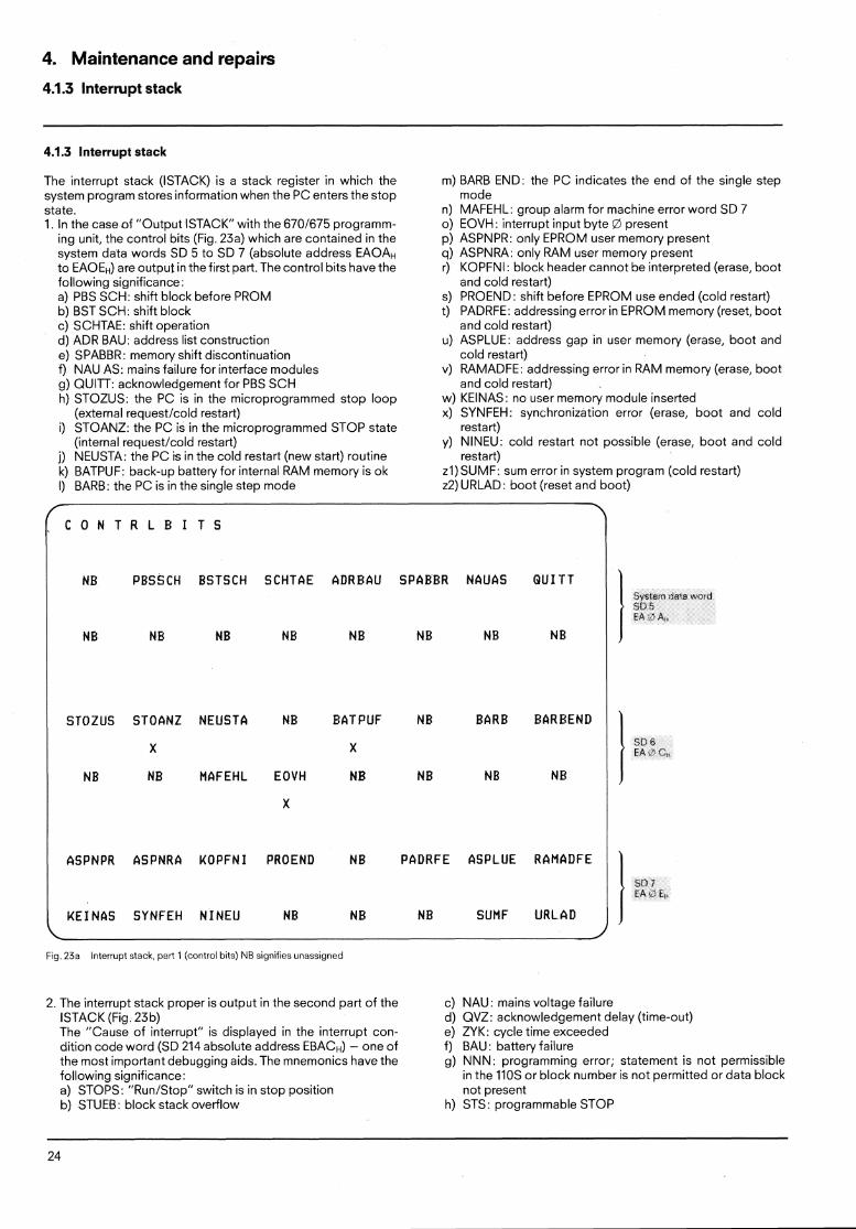
4.1.3 Interrupt stack
4.1.3 Interrupt stack
The interrupt stack (ISTACK) is a stack register in which the system program stores information when the PC enters the stop state. 1. In the case of "Output ISTACK" with the 6701675 programm-
ing unit, the control bits (Fig. 23a) which are contained in the system data words SD 5 to SD 7 (absolute address EAOAH to EAOEH) are output in the first part. The control bits have the following significance: a) PBS SCH: shift block before PROM b) BST SCH: shift block c) SCHTAE: shift operation d) ADR BAU: address list construction e) SPABBR: memory shift discontinuation f) NAU AS: mains failure for interface modules g) QUITT: acknowledgement for PBS SCH h) STOZUS: the PC is in the microprogrammed stop loop
(external requestlcold restart) i) STOANZ: the PC is in the microprogrammed STOP state
(internal requestlcold restart) j) NEUSTA: the PC is in the cold restart (new start) routine k) BATPUF: back-up battery for internal RAM memory is ok I) BARB: the PC is in the single step mode
m) BARB END: the PC indicates the end of the single step mode
n) MAFEHL: group alarm for machine error word SD 7 o) EOVH: interrupt input byte O present p) ASPNPR: only EPROM user memory present q) ASPNRA: only RAM user memory present r) KOPFNI: block header cannot be interpreted (erase, boot
and cold restart) S) PROEND: shift before EPROM use ended (cold restart) t) PADRFE: addressing error in EPROM memory (reset, boot
and cold restart) U) ASPLUE: address gap in user memory (erase, boot and
cold restart) v) RAMADFE: addressing error in RAM memory (erase, boot
and cold restart) W) KEINAS: no user memory module inserted X) SYNFEH: synchronization error (erase, boot and cold
restart) y) NINEU: cold restart not possible (erase, boot and cold
restart) z1)SUMF: sum error in system program (cold restart) 22) URLAD: boot (reset and boot)
\ C O N T R L B I T S
NB PBSSCH BSTSCH SCHTAE ADRBAU SPABBR NAUAS Q U I T T
NB NB NE NB NB NB NB NB
X
ASPNPR ASPNRA KOPFNI PROEND NB PADRFE ASPLUE RAMADFE
517 7 EA c* F!.
KEINAS SYNFEH N I N E U NB NB NB SUMF URLAD
Fig 23a Interrupt stack, part 1 (control bits) NB s~gnifies unassigned
l STOZUS STOANZ NEUSTA NB BATPUF NB BARB BAREEND
X X
NB NB MAFEHL EOVH NB NB NB NB
2. The interrupt stack proper is output in the second part of the ISTACK (Fig 23b) The "Cause of interrupt" is displayed in the interrupt con- dition code word (SD 214 absolute address EBACH) - one of the most important debugging aids. The mnemonics have the following significance: a) STOPS: "RunIStop" switch is in stop position b) STUEB: block stack overflow
l !<D h EA .' 6,
c) NAU: mains voltage failure d) QVZ: acknowledgement delay (time-out) e) ZYK: cycle time exceeded f) BAU: battery failure g) NNN: programming error; statement is not permissible
in the 110s or block number is not permitted or data block not present
h) STS: programmable STOP
4. Maintenance and repairs
4.1.3 Interrupt stack 4.1.4 System parameters
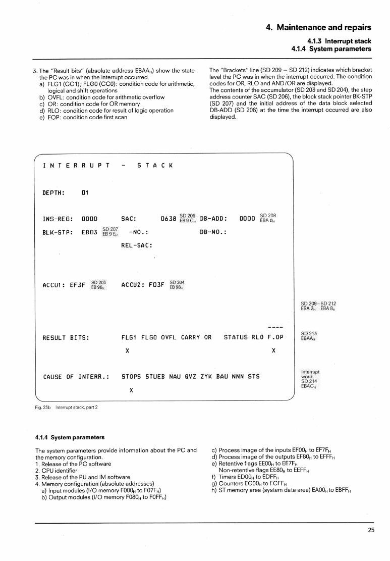
3. The "Result bits" (absolute address EBAAH) show the state the PC was in when the interrupt occurred. a) FLGI (CCI); FLGO (CCO): condition code for arithmetic,
logical and shift operations b) OVFL: condition code for arithmetic overflow c) OR: condition code for OR memory d) RLO: condition code for result of logic operation e) FOP: condition code first scan
The "Brackets" line (SD 209 - SD 212) indicates which bracket level the PC was in when the interrupt occurred. The condition codes for OR, RLO and ANDIOR are displayed. The contents of the accumulator (SD 203 and SD 204), the step address counter SAC (SD 206), the block stack pointer BK-STP (SD 207) and the initial address of the data block selected DB-ADD (SD 208) at the time the interrupt occurred are also displayed.
I N T E R R U P T - S T A C K
DEPTH: 0 1
INS-REG: OOOO SAC: 0 6 3 8 ;ksiu < DE-ADD: OOOO "'?" LEA B, C ? 206
BLK-STp: ~ ~ 0 3 s117c7 fl?'?E, -NO. : DE-NO. :
REL-SAC :
513 209 S!) 21 1 f B A 2 , EBAR
---- RESULT B I T S : F L G I FLGO OVFL CARRY OR STATUS RLO F.OP
/ CAUSE OF INTERR.: STOPS STUEB NAU QVZ ZYK BAU NMN STS l
X
Fig. 23b Interrupt stack, par! 2
4.1.4 System parameters
The system parameters provide information about the PC and c) Process image of the inputs EFOOH to EF~FH the memory configuration. d) Process image of the outputs EF80t. to EFFFH 1. Release of the PC software e) Retentive flags EEOOH to 2. CPU identifier Non-retentive flags EE8OH to EEFFH 3. Release of the PU and IM software f) Timers EDOOH to EDFFH 4. Memory configuration (absolute addresses) g) Counters ECOOH to ECFFH
a) Input modules (110 memory FOOOH to F07FH) h) ST memory area (system data area) EAOOH to EBFFH b) Output modules (110 memory F080~ to FOFFH)
4. Maintenance and repairs
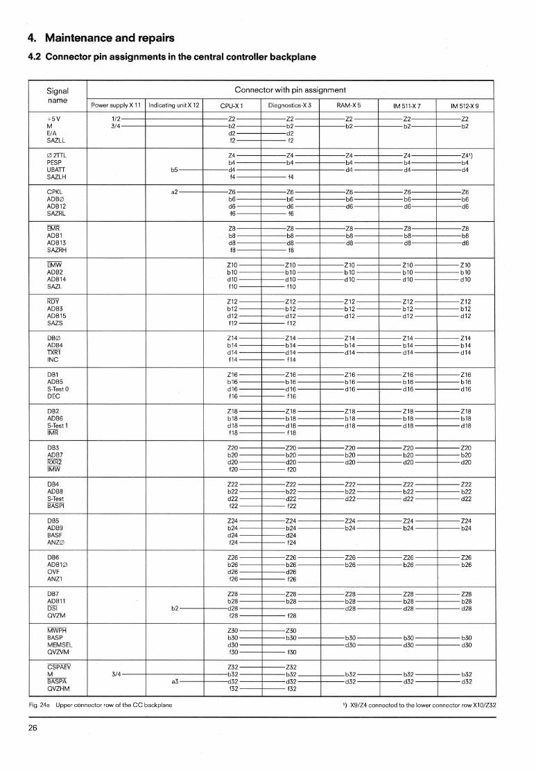
4.2 Connector pin assignments in the central controller backplane
/ Signal I Connector with pin assignment 1
1 5 v
d2 d2 1 SAZLL 1 f2' f2
I name
a 2 r rL
SAZLH
ADBd AD012 SAZRL
a Power supply X 11 I indicating untt X 12 1 CPU-X 1 1 Dtegnostics-X3 / RAM-X 5
RDY AD03 ADB15 SAZS
DBQ ADB4 1 m
IM 511-X 7
DB2
S-Test 1 IMR
IM 512-X 9
DB6 l l 1 226 226 226 AD010 1 b26 b26 b26
d26 AN21 1 126 i26
I DB7 228 228
b28 DSI 1 b2 d28 -- - d28 d28 4:: OVZM i
MEMSEL O V N M 1
BASPA 1 CVZHM p- P P- P P-
F I ~ 24a Upper connector row of the C C hackplane l ) X9/Z4 connected to the lower connector row X10/232
4. Maintenance and repairs
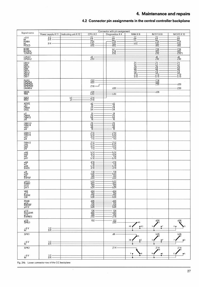
4.2 Connector pin assignments in the central controller backplane
Fig 24b Lower connector row of the CC backplane
4. Maintenance and repairs
4.3 Connector pin assignments of the 110 bus
- -
4.3 Connector pin assignments of the 110 bus Socket connectors
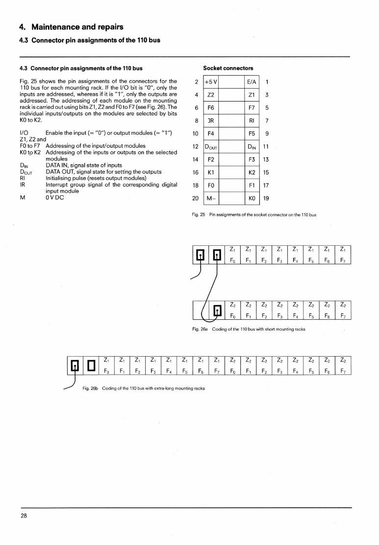
Fig. 25 shows the pin assignments of the connectors for the 110 bus for each mounting rack. If the I10 bit is "0", only the inputs are addressed, whereas if it is "l", only the outputs are addressed. The addressing of each module on the mounting rack is carried out using bitsZl,Z2 and F0 to F7 (see Fig. 26). The individual inputsloutputs on the modules are selected by bits KO to K2.
I10 Enable the input (= "0") or output modules (= "1") ZI,Z2 and F0 to F7 Addressing of the inputloutput modules KO tp K2 Addressing of the inputs or outputs on the selected
modules DIN DATA IN, signal state of inputs DoUT DATA OUT, signal state for setting the outputs R I Initialising pulse (resets output modules) l R Interrupt group signal of the corresponding digital
input module M OVDC
Fig 25 Pin assignments of the socket connector on the 110 bus
Fig. 26a Coding of the 110 bus with short mounting racks
Fig 26b Coding of the 110 bus with extra-long mounting racks

5. Spare parts
Order No Description Weight approx.
kg
Order No
670C Programming unit' consisting of: video monitor with UV erasing unit and printer interface German labelling
We~ght approx.
kg
Housing, complete with power supply 220 V ACl240 V ACl5 V DC
Housing, complete with power supply 115VACI5VDC
Housing, complete w ~ t h power supply 24 V DC15 V D C
CPU
English labelling
6ES5 932-3SA12
6ES5 932-3SA22
6ES5 932-3SA32
6ES5 902-3SA12 French labelling
675 programming unit* consisting of: video monitor with printer interface but without UV erasing unit
Memory submodul for CPU a) with EPROM for 2K statements b) with EPROM for 4K statements c) with EPROM for 8Kstatements
Mounting rack with 8 module locations with 16 module locations
340 Memory module' RAM for 81( statements RAM for 16K statements
350 Memory module' RAM for 4K statements
Associated EPROM submodules' 371 for 2K statements 371 for 4K statements 371 for 8K statements
511 PU interface module'
Cable connector, shielding between C C and IIOs, 0.9 m between C C and I/Os, 1.5 m between C C and IIOs, 2.5 m
Cable connector, shielded between short mounting racks. 0.8 m 1 6155717-OBH. / Cable connector, shielded . between extra-long mounting racks, 0.5 m 1 6ES5718-OAF00 1
512C lnterface module' for compu!er, keyboard prlnter and CRT monitor
Input modules, each with 8 inputs
Digital input module 24 V DC
Digital input module with group signal 24 V DC
Digital input module 115 V ACIDC 220 V ACIDC 48 V AC1DC
302 Serial peripheral interface module* (can be plugged Into central controller) 6ES5 302-5AAll 0 3
731 Cable connector' between 670 PU and 51 1 IM / 6ES5 731 - 0 0 0 0 0 / 732 Cable sonnector between 512 IM and 3913 keyboard printer (TTY)"
3914 keyboard printer (PT80, TTY)*
3964 Data transmission controller (PROMEA)*
3974 (TTY)* Alphanumeric display unit
3974 R (TTY)' Alphanumeric display unit
512 Interface module (SS-S5 interface TTY)'
3964 Data transmission controller*
Length of 731 and 732 cable connectors
l m
Output modules, each with 8 outputs Digital output module 24V DC, 2 A
48 V DC, 0.5 A 115VAC,2 A 220V AC, 2 A
48 V ACl24 V AC, 2 A
Relay output module up to 30 V ACIDCI5OO mA
up to 250 V AClDCl1.5 A
333C Service unit' without connector
Standard function blocks for 333C service unit, on mini-diskette
Fuses for output modules 220 V A C 6 3 A fast
115\1AC 6 3 A f a s t 24 V D C 2 5 A fast
261 312 GWA 261 312 GWA 261 131 GWA
5 m I BFO I Power supply blocks
2201240 V AC, 0.8 A slow 115VAC, 1 6 A s l o w
256 263 GWE 256 255 GWE
40 m I CEO I Power supply modules for external 24 V supply
Back-up battery (Li) 3.4 V 6ES5 980-OAA31
100 m I DBO I
400 m 1 DEO 1
1000 m I EBO 1 736 Cable connector' Length 3.20 m; for connecting a PT80 (TTY) printer to the 6701675 PU
737 Cable connector' Length 3.20 m; for connecting a printer (V.24) to the 6701675 PU
j * Order from GWK
6. Maximum I/O configuration
0.0 . 15.7
Module locati
1 6 0 . , 3 1 7
I F#. . .r .~. . . . . . . . . . . . . . . . . . . . . .,. . . .I.. . . . . . . . . . .g.. . .p.. . . . . . . . . .
Module location -- .
16 17 18 19 20 21 22 23 24 25 26 27 28 29 30 31
3 2 0 . , 4 7 7
Module location
48.0 63 7
Module location
48 49 50 51 52 53 54 55 56 57 58 59 60 61 62 63
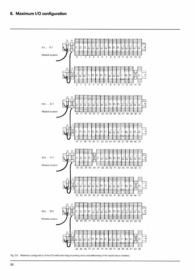
Fig 27a Maximum coni~guration of the 110s with extra-long mounting racks and addressing of the inputloutput modules.
6. Maximum I/O configuration
0 .0 . . . 15.7
Module location
16.0 . . . 31.7
Module location
32.0. . . 47.7
Module location
48.0. . . 63.7
Module location
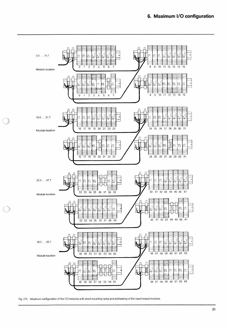
Fig. 27b Maximum configuration of the I10 modules with short mounting racks and addressing of the inputloutput modules.

SIEMENS AKTIENGESELLSCHAFT Order NO. GWA4NEB 807 2121-02 Printed in the Federal Repubiic of Germany AG 07830 3 E 32 en