programmer’s guide to the java 2d api - university of …€¦ · · 2000-12-19i programmer’s...
TRANSCRIPT

i
Programmer’s Guide to theJava 2D™ API
Enhanced Graphics and Imaging for Java
JavaTM 2 SDK, Standard Edition, 1.3 Version
November 19, 1999
2550 Garcia AvenueMountain View, CA 94043 USA415 960-1300 fax 415 969-9131
A Sun Microsystems, Inc. Business


iii
is27-
oreign
arks or
)
1998, 1999 Sun Microsystems, Inc.2550 Garcia Avenue, Mountain View, California 94043-1100 U.S.A.All rights reserved.
RESTRICTED RIGHTS LEGEND : Use, duplication, or disclosure by the U.S. Governmentsubject to restrictions of FAR 52.227-14(g)(2)(6/87) and FAR 52.227-19(6/87), or DFAR 252.27015(b)(6/95) and DFAR 227.7202-1(a).
The release described in this document may be protected by one or more U.S. patents, fpatents, or pending applications.
Sun, the Sun logo, Sun Microsystems, JDK, Java, and the Java Coffee Cup logo are trademregistered trademarks of Sun Microsystems, Inc. in the United States and other countries.
THIS PUBLICATION IS PROVIDED “AS IS” WITHOUT WARRANTY OF ANY KIND,EITHER EXPRESS OR IMPLIED, INCLUDING, BUT NOT LIMITED TO, THE IMPLIEDWARRANTIES OF MERCHANTABILITY, FITNESS FOR A PARTICULAR PURPOSE, ORNON-INFRINGEMENT.
THIS PUBLICATION COULD INCLUDE TECHNICAL INACCURACIES ORTYPOGRAPHICAL ERRORS. CHANGES ARE PERIODICALLY ADDED TO THEINFORMATION HEREIN; THESE CHANGES WILL BE INCORPORATED IN NEWEDITIONS OF THE PUBLICATION. SUN MICROSYSTEMS, INC. MAY MAKEIMPROVEMENTS AND/OR CHANGES IN THE PRODUCT(S) AND/OR THE PROGRAM(SDESCRIBED IN THIS PUBLICATION AT ANY TIME


1
2 . 2 . 4 . 5 . 6 . 7 . 7
810
0
5
5
6. 177191222325
2779
Contents
Java 2DTM API Overview. . . . . . . . . . . . . . . . . . . . . . . . . . . . . . . .
Enhanced Graphics, Text, and Imaging . . . . . . . . . . . . . . . 1
Rendering Model . . . . . . . . . . . . . . . . . . . . . . . . . . . . . . . . .Coordinate Systems . . . . . . . . . . . . . . . . . . . . . . . . . . . . . . . .Transforms. . . . . . . . . . . . . . . . . . . . . . . . . . . . . . . . . . . . . . .Fonts . . . . . . . . . . . . . . . . . . . . . . . . . . . . . . . . . . . . . . . . . . .Images . . . . . . . . . . . . . . . . . . . . . . . . . . . . . . . . . . . . . . . . . .Fills and Strokes . . . . . . . . . . . . . . . . . . . . . . . . . . . . . . . . . .Composites . . . . . . . . . . . . . . . . . . . . . . . . . . . . . . . . . . . . . .
Backward Compatibility and Platform Independence . . . 8Backward Compatibility . . . . . . . . . . . . . . . . . . . . . . . . . . . . .Platform Independence . . . . . . . . . . . . . . . . . . . . . . . . . . . . .
The Java 2D™ API Packages . . . . . . . . . . . . . . . . . . . . . . 1
Rendering with Graphics2D . . . . . . . . . . . . . . . . . . . . . . . . . . . . . 1
Interfaces and Classes . . . . . . . . . . . . . . . . . . . . . . . . . . . . 1
Rendering Concepts . . . . . . . . . . . . . . . . . . . . . . . . . . . . . . 1Rendering Process . . . . . . . . . . . . . . . . . . . . . . . . . . . . . . . . Controlling Rendering Quality . . . . . . . . . . . . . . . . . . . . . . . 1Stroke Attributes . . . . . . . . . . . . . . . . . . . . . . . . . . . . . . . . . .Fill Attributes. . . . . . . . . . . . . . . . . . . . . . . . . . . . . . . . . . . . . 2Clipping Paths . . . . . . . . . . . . . . . . . . . . . . . . . . . . . . . . . . . .Transformations. . . . . . . . . . . . . . . . . . . . . . . . . . . . . . . . . . .Composite Attributes. . . . . . . . . . . . . . . . . . . . . . . . . . . . . . .
Setting Up the Graphics2D Context . . . . . . . . . . . . . . . . . 27Setting Rendering Hints . . . . . . . . . . . . . . . . . . . . . . . . . . . .Specifying Stroke Attributes . . . . . . . . . . . . . . . . . . . . . . . . . 2Specifying Fill Attributes . . . . . . . . . . . . . . . . . . . . . . . . . . . 2
v

vi
323334
.36.37.38.38
43
43
54546
6
7
9
49
51
2.535456561
2636364646565
Setting the Clipping Path . . . . . . . . . . . . . . . . . . . . . . . . . . . .Setting the Graphics2D Transform . . . . . . . . . . . . . . . . . . . .Specifying a Composition Style. . . . . . . . . . . . . . . . . . . . . . .
Rendering Graphics Primitives . . . . . . . . . . . . . . . . . . . . .36Drawing a Shape . . . . . . . . . . . . . . . . . . . . . . . . . . . . . . . . . Filling a Shape . . . . . . . . . . . . . . . . . . . . . . . . . . . . . . . . . . . Rendering Text. . . . . . . . . . . . . . . . . . . . . . . . . . . . . . . . . . . Rendering Images. . . . . . . . . . . . . . . . . . . . . . . . . . . . . . . . .
Defining Custom Composition Rules . . . . . . . . . . . . . . . .38
Rendering in a Multi-Screen Environment . . . . . . . . . . .39
Geometries . . . . . . . . . . . . . . . . . . . . . . . . . . . . . . . . . . . . . . . . . . .
Interfaces and Classes . . . . . . . . . . . . . . . . . . . . . . . . . . . . .
Geometry Concepts . . . . . . . . . . . . . . . . . . . . . . . . . . . . . . .4Constructive Area Geometry . . . . . . . . . . . . . . . . . . . . . . . . .Bounds and Hit Testing . . . . . . . . . . . . . . . . . . . . . . . . . . . . .
Combining Areas to Create New Shapes . . . . . . . . . . . . .4
Creating a Custom Shape . . . . . . . . . . . . . . . . . . . . . . . . . .4
Fonts and Text Layout . . . . . . . . . . . . . . . . . . . . . . . . . . . . . . . . . 4
Interfaces and Classes . . . . . . . . . . . . . . . . . . . . . . . . . . . . .
Font Concepts . . . . . . . . . . . . . . . . . . . . . . . . . . . . . . . . . . .
Text Layout Concepts . . . . . . . . . . . . . . . . . . . . . . . . . . . . .5Shaping Text . . . . . . . . . . . . . . . . . . . . . . . . . . . . . . . . . . . . Ordering Text . . . . . . . . . . . . . . . . . . . . . . . . . . . . . . . . . . . . .Measuring and Positioning Text . . . . . . . . . . . . . . . . . . . . . .Supporting Text Manipulation . . . . . . . . . . . . . . . . . . . . . . . .Performing Text Layout in a Java™ Application . . . . . . . . .6
Managing Text Layout . . . . . . . . . . . . . . . . . . . . . . . . . . . .6Laying Out Text . . . . . . . . . . . . . . . . . . . . . . . . . . . . . . . . . . .Displaying Dual Carets . . . . . . . . . . . . . . . . . . . . . . . . . . . . .Moving the Caret . . . . . . . . . . . . . . . . . . . . . . . . . . . . . . . . . .Hit Testing . . . . . . . . . . . . . . . . . . . . . . . . . . . . . . . . . . . . . . .Highlighting Selections . . . . . . . . . . . . . . . . . . . . . . . . . . . . .Querying Layout Metrics . . . . . . . . . . . . . . . . . . . . . . . . . . . .

vii
6
71
7272. 72. 73. 7475
. 76
78
879928383
. 84
. 84
. 84. 85
5
87
7. 89
93
. 93
Drawing Text Across Multiple Lines . . . . . . . . . . . . . . . . . . 6
Implementing a Custom Text Layout Mechanism . . . . . 67
Creating Font Derivations . . . . . . . . . . . . . . . . . . . . . . . . . 69
Imaging . . . . . . . . . . . . . . . . . . . . . . . . . . . . . . . . . . . . . . . . . . . . . .
Interfaces and Classes . . . . . . . . . . . . . . . . . . . . . . . . . . . .Imaging Interfaces . . . . . . . . . . . . . . . . . . . . . . . . . . . . . . . . .Image Data Classes . . . . . . . . . . . . . . . . . . . . . . . . . . . . . . . Image Operation Classes . . . . . . . . . . . . . . . . . . . . . . . . . . . Sample Model Classes. . . . . . . . . . . . . . . . . . . . . . . . . . . . . Color Model Classes . . . . . . . . . . . . . . . . . . . . . . . . . . . . . . .Exception Classes . . . . . . . . . . . . . . . . . . . . . . . . . . . . . . . .
Immediate Mode Imaging Concepts . . . . . . . . . . . . . . . . . 76Terminology . . . . . . . . . . . . . . . . . . . . . . . . . . . . . . . . . . . . .
Using BufferedImages . . . . . . . . . . . . . . . . . . . . . . . . . . . . 7Creating a BufferedImage . . . . . . . . . . . . . . . . . . . . . . . . . . .Drawing in an Offscreen Buffer . . . . . . . . . . . . . . . . . . . . . . 7Manipulating BufferedImage Data Directly . . . . . . . . . . . . . 8Filtering a BufferedImage . . . . . . . . . . . . . . . . . . . . . . . . . . .Rendering a BufferedImage. . . . . . . . . . . . . . . . . . . . . . . . . .
Managing and Manipulating Rasters . . . . . . . . . . . . . . . . 83Creating a Raster . . . . . . . . . . . . . . . . . . . . . . . . . . . . . . . . . Parent and Child Rasters . . . . . . . . . . . . . . . . . . . . . . . . . . . Operations on a Raster. . . . . . . . . . . . . . . . . . . . . . . . . . . . . The WritableRaster Subclass. . . . . . . . . . . . . . . . . . . . . . . .
Image Data and DataBuffers . . . . . . . . . . . . . . . . . . . . . . . 8
Extracting Pixel Data from a SampleModel . . . . . . . . . . 85
ColorModels and Color Data . . . . . . . . . . . . . . . . . . . . . . . 86Lookup Table. . . . . . . . . . . . . . . . . . . . . . . . . . . . . . . . . . . . .
Image Processing and Enhancement . . . . . . . . . . . . . . . . 8Using an Image Processing Operation. . . . . . . . . . . . . . . . .
Color. . . . . . . . . . . . . . . . . . . . . . . . . . . . . . . . . . . . . . . . . . . . . . . . .
Classes . . . . . . . . . . . . . . . . . . . . . . . . . . . . . . . . . . . . . . . .

viii
94978
01
02
203104.105607
0910
11415
Color Concepts . . . . . . . . . . . . . . . . . . . . . . . . . . . . . . . . . .Describing Colors. . . . . . . . . . . . . . . . . . . . . . . . . . . . . . . . . .Mapping Colors through sRGB and CIEXYZ. . . . . . . . . . . .9
Printing. . . . . . . . . . . . . . . . . . . . . . . . . . . . . . . . . . . . . . . . . . . . . 1
Interfaces and Classes . . . . . . . . . . . . . . . . . . . . . . . . . . . .1
Printing Concepts . . . . . . . . . . . . . . . . . . . . . . . . . . . . . . .10Supporting Printing . . . . . . . . . . . . . . . . . . . . . . . . . . . . . . .1Page Painters . . . . . . . . . . . . . . . . . . . . . . . . . . . . . . . . . . . .Printable Jobs and Pageable Jobs. . . . . . . . . . . . . . . . . . . . Typical Life-Cycle of a PrinterJob. . . . . . . . . . . . . . . . . . . .10Dialogs . . . . . . . . . . . . . . . . . . . . . . . . . . . . . . . . . . . . . . . . .1
Printing with Printables . . . . . . . . . . . . . . . . . . . . . . . . . .108Using Graphics2D for Rendering. . . . . . . . . . . . . . . . . . . . .1Printing a File . . . . . . . . . . . . . . . . . . . . . . . . . . . . . . . . . . . .1
Printing with Pageables and Books . . . . . . . . . . . . . . . . .113Using a Pageable Job . . . . . . . . . . . . . . . . . . . . . . . . . . . . . .Using Multiple Page Painters. . . . . . . . . . . . . . . . . . . . . . . .1

tes addi-
n:
I.
day-
Preface
This guide describes the features provided by the Java 2D™ API and illustrahow you can use the Java 2D API classes to enhance your applications. Fortional information about the Java 2D APIs, see:
• The Java Tutorial, 2nd Volume. Available online at:http://java.sun.com/docs/books/tutorial/2d/index.html
• The 2D Text Tutorial. Available online from the Java Developer Connectiohttp://developer.java.sun.com/developer/onlineTraining/
Graphics/2DText/
• The Java 2D Sample Programs. Available online at:http://java.sun.com/products/java-media/2D/samples/index.html
• The Java 2D Demo. Available from the Java 2D website:http://java.sun.com/products/java-media/2D/index.html
This information in this guide is organized into seven chapters:
Overview —introduces the packages and key classes in the Java 2D AP
Rendering with Graphics2D—describes the Java 2D API classes in thejava.awt package and how to set up theGraphics2D rendering context.
Geometries—describes the Java 2D API classes in thejava.awt.geom
package and how to define and manipulate 2D shapes and areas.
Fonts and Text Layout—describes the Java 2D API classes in thejava.awt.font package, how to specify and retrieve font information, anhow to display and manipulate international text using the Java 2D text lout APIs directly.
Imaging—describes the Java 2D API classes in thejava.awt.image,java.awt.image.codec, andjava.awt.image.renderable packages andhow to display and manipulate images and offscreen buffers.
Color—describes the Java 2D API classes in thejava.awt.color packageand color management.
Printing —describes the Java 2D API classes in thejava.awt.print pack-age and the Java 2D API printing model.
ix

Preface, JavaTM 2 SDK, Standard Edition, 1.3 Versionx
1
the
ortsicces.
ch asas
ediaherPIs
en-cs,
es aort
ngava vir-
Java 2DTM API Overview
The Java 2D™ API enhances the graphics, text, and imaging capabilities of Abstract Windowing Toolkit (AWT), enabling the development of richer userinterfaces and new types of Java™ applications.
Along with these richer graphics, font, and image APIs, the Java 2D API suppenhanced color definition and composition, hit detection on arbitrary geometrshapes and text, and a uniform rendering model for printers and display devi
The Java 2D API also enables the creation of advanced graphics libraries, suCAD-CAM libraries and graphics or imaging special effects libraries, as well the creation of image and graphic file read/write filters.
When used in conjunction with the Java Media Framework and other Java MAPIs, the Java 2D APIs can be used to create and display animations and otmultimedia presentations. The Java Animation and Java Media Framework Arely on the Java 2D API for rendering support.
1.1 Enhanced Graphics, Text, and Imaging
Early versions of the AWT provided a simple rendering package suitable for rdering common HTML pages, but not full-featured enough for complex graphitext, or imaging. As a simplified rendering package, the early AWT embodiedspecific cases of more general rendering concepts. The Java 2D™ API providmore flexible, full-featured rendering package by expanding the AWT to suppmore general graphics and rendering operations.
For example, through theGraphics class you can draw rectangles, ovals, andpolygons.Graphics2D enhances the concept of geometric rendering by providia mechanism for rendering virtually any geometric shape. Similarly, with the J2D API you can draw styled lines of any width and fill geometric shapes withtually any texture.
1

Java 2DTM API Overview, JavaTM 2 SDK, Standard Edition, 1.3 Version2
Javaren-
ices thering
ort
Geometric shapes are provided through implementations of theShape interface,for exampleRectangle2D andEllipse2D. Curves and arcs are also specificimplementations ofShape.
Fill and pen styles are provided through implementations of thePaint andStroke interfaces, for exampleBasicStroke, GradientPaint, TexturePaint,andColor.
AffineTransform defineslinear transformations of 2D coordinates, including
scale, translate, rotate, and shear.
Clip regions are defined by the same implementations of theShape interface thatare used to define general clipping regions, for exampleRectangle2D andGener-alPath.
Color composition is provided by implementations of theComposite interface,for exampleAlphaComposite.
A Font is defined by collections ofGlyphs, which are in turn defined by individ-ualShapes.
1.2 Rendering Model
The basic graphics rendering model has not changed with the addition of the2D™ APIs. To render a graphic, you set up the graphics context and invoke adering method on theGraphics object.
The Java 2D API classGraphics2D extendsGraphics to support more graphicsattributes and provide new rendering methods. Setting up aGraphics2D context isdescribed in “Rendering with Graphics2D” on page 15.
The Java 2D API automatically compensates for differences in rendering devand provides a uniform rendering model across different types of devices. Atapplication level, the rendering process is the same whether the target rendedevice is a display or a printer.
With the JavaTM 2 SDK, version 1.3 relsease, the Java 2D API provides suppfor multi-screen environments. See Section 1.2.1, “Coordinate Systems” and“Rendering in a Multi-Screen Environment” on page 39 for more information.
1.2.1 Coordinate Systems
The Java 2D API maintains two coordinate systems:

Rendering Model 3
ns 2D
ding
nmsses
nt”
eencoor-
r of.
e sys-ndrdi- ased
• User spaceis a device-independent, logical coordinate system. Applicatiouse this coordinate system exclusively; all geometries passed into Javarendering routines are specified in user space.
• Device space is a device-dependent coordinate system that varies accorto the target rendering device.In a multi-screen environment with a virtual desktop where a window caspan more than one physical screen device, the device coordinate systethat’s used is the coordinate system of the virtual desktop that encompaall of the screens. For more information on how the Java 2DTM API supportsmulti-screen environments, see “Rendering in a Multi-Screen Environmeon page 39.
The Java 2D system automatically performs the necessary conversions betwuser space and the device space of the target rendering device. Although thedinate system for a monitor is very different from the coordinate system for aprinter, these differences are invisible to applications.
1.2.1.1 User Space
As shown in Figure 1-1, the user space origin is located in the upper-left cornethe space, withx values increasing to the right andy values increasing downward
Figure 1-1 User Space Coordinate System
User space represents a uniform abstraction of all possible device coordinattems. The device space for a particular device might have the same origin adirection as user space, or it might be different. Regardless, user space coonates are automatically transformed into the appropriate device space whengraphic object is rendered. Often, the underlying platform device drivers are uto perform this conversion.
y
x(0,0)

Java 2DTM API Overview, JavaTM 2 SDK, Standard Edition, 1.3 Version4
in-a-
aceed to
eens,
a a
incol-
ateare
-ed
orm
1.2.1.2 Device Space
The Java 2D API defines three levels of configuration information that are matained to support the conversion from user space to device space. This informtion is encapsulated by three classes:
• GraphicsEnvironment
• GraphicsDevice
• GraphicsConfiguration
Between them, theGraphicsEnvironment, GraphicsDevice, andGraphicsCon-figuration represent all of the information necessary for locating a renderingdevice or font on the Java platform and for converting coordinates from user spto device space. An application can access this information, but does not neperform any transformations between user space and device space.
TheGraphicsEnvironment describes the collection of rendering devices visiblto a Java application on a particular platform. Rendering devices include screprinters, and image buffers. TheGraphicsEnvironment also includes a list of allof the available fonts on the platform.
A GraphicsDevice describes an application-visible rendering device, such asscreen or printer. Each possible configuration of the device is represented byGraphicsConfiguration. For example, an SVGA display device can operate several modes: 640x480x16 colors, 640x480x256 colors, and 800x600x256 ors. The SVGA screen is represented by aGraphicsDevice object and each ofthe modes is represented by aGraphicsConfiguration object.
A GraphicsEnvironment can contain one or moreGraphicsDevices; in turn,eachGraphicsDevice can have one or moreGraphicsConfigurations.
1.2.2 Transforms
The Java 2D API has a unified coordinate transformation model. All coordintransformations, including transformations from user to device space,represented byAffineTransform objects.AffineTransform defines the rules formanipulating coordinates using matrices.
You can add anAffineTransform to the graphics context to rotate, scale, translate, or shear a geometric shape, text, or image when it is rendered. The addtransform is applied to any graphic object rendered in that context. The transf

Rendering Model 5
ordi-
theat islwaysing,ingle
ed
nynt
ntts
fonte,cesk-
cal
tipleof the
is performed when user space coordinates are converted to device space conates.
1.2.3 Fonts
A string is commonly thought of in terms of the characters that comprisestring. When a string is drawn, its appearance is determined by the font thselected. However, the shapes that the font uses to display the string don’t acorrespond to individual characters. For example, in professional publishcertain combinations of two or more characters are often replaced by a sshape called aligature.
The shapes that a font uses to represent the characters in the string are callglyphs. A font might represent a character such as a lowercasea acute using mul-tiple glyphs, or represent certain character combinations such as thefi in final witha single glyph. In the Java 2D API, a glyph is simply aShape that can be manipu-lated and rendered in the same way as any otherShape.
A fontcan be thought of as a collection of glyphs. A single font might have maversions, such as heavy, medium, oblique, gothic, and regular. These differeversions are calledfaces. All of the faces in a font have a similar typographicdesign and can be recognized as members of the samefamily. In other words, acollection of glyphs with a particular style forms a font face, a collection of fofaces forms a font family, and a collection of font families forms the set of fonavailable within a particularGraphicsEnvironment.
In the Java 2D API, fonts are specified by a name that describes a particularface—for example, Helvetica Bold. This is different from the JDK 1.1 softwarin which fonts are described by logical names that map onto different font fadepending on which font faces are available on a particular platform. For bacward compatibility, the Java 2D API supports the specification of fonts by loginame as well as by font face name.
Using the Java 2D API, you can compose and render strings that contain mulfonts of different families, faces, sizes, and even languages. The appearancetext is kept logically separate from the layout of the text.Font objects are used todescribe the appearance, and the layout information is stored inTextLayout andTextAttributeSet objects. Keeping the font and layout information separatemakes it easier to use the same fonts in different layout configurations.

Java 2DTM API Overview, JavaTM 2 SDK, Standard Edition, 1.3 Version6
s is
for
lyloca-look
eci-
alue,rmat
. For
ed,irectle
g
1.2.4 Images
Images are collections of pixels organized spatially. Apixel defines the appear-ance of an image at a single display location. A two-dimensional array of pixelcalled araster.
The pixel’s appearance can be defined directly or as an index into a color tablethe image.
In images that contain many colors (more than 256), the pixels usually directrepresent the color, alpha, and other display characteristics for each screen tion. Such images tend to be much larger than indexed-color images, but theymore realistic.
In an indexed-color image, the colors in the image are limited to the colors spfied in the color table, often resulting in fewer colors that can be used in theimage. However, an index typically requires less storage space than a color vso images stored as a set of indexed colors are usually smaller. This pixel fois popular for images that contain only 16 or 256 colors.
Images in the Java 2D API have two primary components:
• The raw image data (the pixels)
• The information necessary for interpreting the pixels
The rules for interpreting the pixel are encapsulated by aColorModel object—forexample, whether the values should be interpreted as direct or indexed colorsa pixel to be displayed, it must be paired with a color model.
A band is one component of the color space for an image. For example, the RGreen, and Blue components are the bands in an RGB image. A pixel in a dcolor model image can be thought of as a collection of band values for a singscreen location.
Thejava.awt.image package contains severalColorModel implementations,including those for packed and component pixel representations.
A ColorSpace object encapsulates the rules that govern how a set of numericmeasurements corresponds to a particular color. TheColorSpace implementa-tions in thejava.awt.color represent the most popular color spaces, includinRGB and gray scale. Note that a color space isnot a collection of colors—itdefines the rules for how to interpret individual color values.

Rendering Model 7
s can
es.
di-
rs.
two
ng
d
o get
mineupyhow
ing des-
Separating the color space from the color model provides greater flexibility inhow colors are represented and converted from one color representation toanother.
1.2.5 Fills and Strokes
With the Java 2D API, you can renderShapes using different pen styles and fillpatterns. Because text is ultimately represented by a set of glyphs, text stringalso be stroked and filled.
Pen styles are defined by objects that implement theStroke interface. Strokesenable you to specify different widths and dashing patterns for lines and curv
Fill patterns are defined by objects that implement thePaint interface. TheColorclass, which was available in earlier versions of the AWT, is a simple type ofPaint object used to define solid-color fills. The Java 2D API provides two adtionalPaint implementations,TexturePaint andGradientPaint. Texture-Paint defines a fill pattern using a simple image fragment that is repeateduniformly. GradientPaint defines a fill pattern as a gradient between two colo
In Java 2D, rendering a shape’s outline and filling the shape with a pattern areseparate operations:
• Using one of thedraw methods renders the shape’s contour or outline usithe pen style specified by theStroke attribute and the fill pattern specified bythePaint attribute.
• Using thefillmethod fills the interior of the shape with the pattern specifieby thePaint attribute.
When a text string is rendered, the currentPaint attribute is applied to the glyphsthat form the string. Note, however, thatdrawString actually fills the glyphs thatare rendered. To stroke the outlines of the glyphs in a text string, you need tthe outlines and render them as shapes using thedraw method.
1.2.6 Composites
When you render an object that overlaps an existing object, you need to deterhow to combine the colors of the new object with the colors that already occthe area where you are going to draw. The Java 2D API encapsulates rules forto combine colors in aComposite object.
Primitive rendering systems provide only basic Boolean operators for combincolors. For example, a Boolean compositing rule might allow the source and

Java 2DTM API Overview, JavaTM 2 SDK, Standard Edition, 1.3 Version8
ms
s in
ofannot
col-
It
nd
Javainrfaces
ses a
n-
tination color values to be ANDed, ORed, or XORed. There are several problewith this approach
• It’s not “human friendly”—it’s difficult to think in terms of what the resultingcolor will be if red and blue are ANDed, not added.
• Boolean composition does not support the accurate composition of colordifferent color spaces.
• Straight Boolean composition doesn’t take into account the color modelsthe colors. For example, in an indexed color model, the result of a Booleoperation on two pixel values in an image is the composite of two indices,two colors.
The Java 2D API avoids these pitfalls by implementing alpha-blending1 rules thattake color model information into account when compositing colors. AnAlpha-
Composite object includes the color model of both the source and destinationors.
1.3 Backward Compatibility and Platform Independence
The Java 2D™ API maintains backward compatibility with JDK 1.1 software.is also architected so that applications can maintain platform-independence.
1.3.1 Backward Compatibility
To ensure backward compatibility, the functionality of existing JDK graphics aimaging classes and interfaces was maintained. Existing features were notremoved and no package designations were changed for existing classes. The2D API enhances the functionality of the AWT by implementing new methodsexisting classes, extending existing classes, and adding new classes and intethat don’t affect the legacy APIs.
For example, much of the Java 2D API functionality is delivered through anexpanded graphics context,Graphics2D. To provide this extended graphics con-text while maintaining backward compatibility,Graphics2D extends theGraph-ics class from the JDK 1.1 release.
The usage model of the graphics context remains unchanged. The AWT pasgraphics context to an AWTComponent through the following methods:
1. For detailed information about alpha blending, see Section 17.6 ofComputer Graphics:Principles and Practice. 2nd ed. J.D. Foley, A. van Dam, S.K. Feiner, J.F. Hughes. AddisoWesley, 1990.

Backward Compatibility and Platform Independence 9
ce of
alizes
classo add
This
• paint
• paintAll
• update
• printAll
• getGraphics
A JDK 1.1 applet interprets the graphics context that’s passed in as an instanGraphics. To gain access to the new features implemented inGraphics2D, aJava 2D API–compatible applet casts the graphics context to aGraphics2D
object:
public void Paint (Graphics g) {
Graphics2D g2 = (Graphics2D) g;......g2.setTransform (t);
}
In some cases, rather than extending a legacy class, the Java 2D API generit. Two techniques were used to generalize legacy classes:
• One or more parent classes were inserted in the hierarchy, and the legacywas updated to extend the new parent classes. This technique is used tgeneral implemented methods and instance data to the legacy class.
• One or more interface implementations were added to the legacy class.technique is used to add general abstract methods to the legacy class.
For example, the Java 2D API generalizes the AWTRectangle class using bothof these techniques. The hierarchy for rectangle now looks like:
java.lang.object|+-------java.awt.geom.RectangularShape | +---------java.awt.geom.Rectangle2D | +-------java.awt.Rectangle
Java 2DTM API Overview, JavaTM 2 SDK, Standard Edition, 1.3 Version10
r-
.
al” to— con-
le
APIe tar-e file
ro-n orn of
izes
In the JDK 1.1 software,Rectangle simply extendedObject. It now extends thenewRectangle2D class and implements bothShape andSerializable. Two par-ent classes were added to theRectangle hierarchy:RectangularShape andRectangle2D. Applets written for JDK 1.1 software are unaware of the new paent classes and interface implementations, but are unaffected becauseRectangle
still contains the methods and members that were present in earlier versions
The Java 2D API adds several new classes and interfaces that are “orthogonthe legacy API. These additions do not extend or generalize existing classesthey are entirely new and distinct. These new classes and interfaces embodycepts that had no explicit representation in the legacy API.
For example, the Java 2D API implements several newShape classes, includingArc2D, CubicCurve2D, andQuadCurve2D. Although early versions of the AWTcould render arcs using thedrawArc andfillArc methods, there was no generacurve abstraction and no discrete classes that embodied arcs. These discretclasses could be added to the Java 2D API without disrupting legacy appletsbecausedrawArc andfillArc are still supported through theGraphics class.
1.3.2 Platform Independence
To enable the development of platform-independent applications, the Java 2Dmakes no assumptions about the resolution, color space, or color model of thget rendering device. Nor does the Java 2D API assume any particular imagformat.
Truly platform-independent fonts are possible only when the fonts are built-in(provided as part of the JDK software), or when they are mathematically or pgrammatically generated. The Java 2D API does not currently support built-imathematically generated fonts, but it does enable the programmatic definitioentire fonts through their glyph set. Each glyph can in turn be defined by aShape
that consists of line segments and curves. Many fonts of particular styles and scan be derived from a single glyph set.
1.4 The Java 2D™ API Packages
The Java 2D API classes are organized into the following packages:
• java.awt
• java.awt.geom
• java.awt.font

The Java 2D™ API Packages 11
gen-es in
ion
reci-
• java.awt.color
• java.awt.image
• java.awt.image.renderable
• java.awt.print
Packagejava.awt contains those Java 2D API classes and interfaces that areeral in nature or that enhance legacy classes. (Obviously, not all of the classjava.awt are Java 2D classes.)
Package java.awt.geom contains classes and interfaces related to the definitof geometric primitives:
Many of the geometric primitives have corresponding.Float and.Doubleimplementations. This was done to enable both floating single- and double-p
AlphaComposite BasicStroke Color
Composite CompositeContext Font
GradientPaint Graphics2D GraphicsConfiguration
GraphicsDevice GraphicsEnvironment Paint
PaintContext Rectangle Shape
Stroke TexturePaint Transparency
AffineTransform Arc2D Arc2D.Double
Arc2D.Float Area CubicCurve2D
CubicCurve2D.Double CubicCurve2D.Float Dimension2D
Ellipse2D Ellipse2D.Double Ellipse2D.Float
FlatteningPathIterator GeneralPath Line2D
Line2D.Double Line2D.Float PathIterator
Point2D Point2D.Double Point2D.Float
QuadCurve2D QuadCurve2D.Double QuadCurve2D.Float
Rectangle2D Rectangle2D.Double Rectangle2D.Float
RectangularShape RoundRectangle2D RoundRectangle2D.Double
RoundRectangle2D.Float

Java 2DTM API Overview, JavaTM 2 SDK, Standard Edition, 1.3 Version12
der-
nd
sion implementations. Double-precision implementations provide greater rening precision at the expense of performance on some platforms.
Packagejava.awt.font contains classes and interfaces used for text layout athe definition of fonts:
Packagejava.awt.color contains classes and interfaces for the definition ofcolor spaces and color profiles:
Thejava.awt.image andjava.awt.image.renderable packages containclasses and interfaces for the definition and rendering of images:
FontRenderContext GlyphJustificationInfo GlyphMetrics
GlyphVector GraphicAttribute ImageGraphicAttribute
LineBreakMeasurer LineMetrics MultipleMaster
OpenType ShapeGrapicAttribute TextAttribute
TextHitInfo TextLayout TransformAttribute
ColorSpace ICC_ColorSpace ICC_Profile
ICC_ProfileGray ICC_ProfileRGB
AffineTransformOp BandCombineOp BandedSampleModel
BufferedImage BufferedImageFilter BufferedImageOp
ByteLookupTable ColorConvertOp ColorModel
ComponentColorModel ComponentSampleModel ConvolveOp
ContextualRenderedImageFactory DataBuffer
DataBufferByte DataBufferInt DataBufferShort
DataBufferUShort DirectColorModel IndexColorModel
Kernel LookupOp LookupTable
MultiPixelPackedSampleModel PackedColorModel ParameterBlock
PixelInterleavedSampleModel Raster RasterOp
RenderableImage RenderableImageOp RenderableImageProducer
RenderContext RenderedImageFactory RenderedImage
RescaleOp SampleModel ShortLookupTable

The Java 2D™ API Packages 13
of
Packagejava.awt.image was present in earlier versions of the AWT. The Java2D API enhances the following legacy AWT image classes:
• ColorModel
• DirectColorModel
• IndexColorModel
These color model classes remain in thejava.awt.image package for backwardcompatibility. To maintain consistency, the new color model classes are alsolocated in thejava.awt.image package.
Package java.awt.print contains classes and interfaces that enable printingall Java 2D–based text, graphics, and images.
SinglePixelPackedSampleModel TileObserver
WritableRaster WritableRenderedImage
Book Pageable PageFormat
Paper Printable PrinterGraphics
PrinterJob

Java 2DTM API Overview, JavaTM 2 SDK, Standard Edition, 1.3 Version14

2
pro-
thest of
a.
on.
ed
Rendering with Graphics2D
Graphics2D extendsjava.awt.Graphics to provide more sophisticated controlover the presentation of shapes, text, and images. The Java 2D™ rendering cess is controlled through theGraphics2D object and its state attributes.
TheGraphics2D state attributes, such as line styles and transformations, areapplied to graphic objects when they are rendered. The collection of stateattributes associated with aGraphics2D is referred to as theGraphics2D context.To render text, shapes, or images, you set up theGraphics2D context and then callone of theGraphics2D rendering methods, such asdraw or fill.
2.1 Interfaces and Classes
The following tables list the interfaces and classes used in conjunction withGraphics2D context, including the classes that represent state attributes. Mothese classes are part of thejava.awt package.
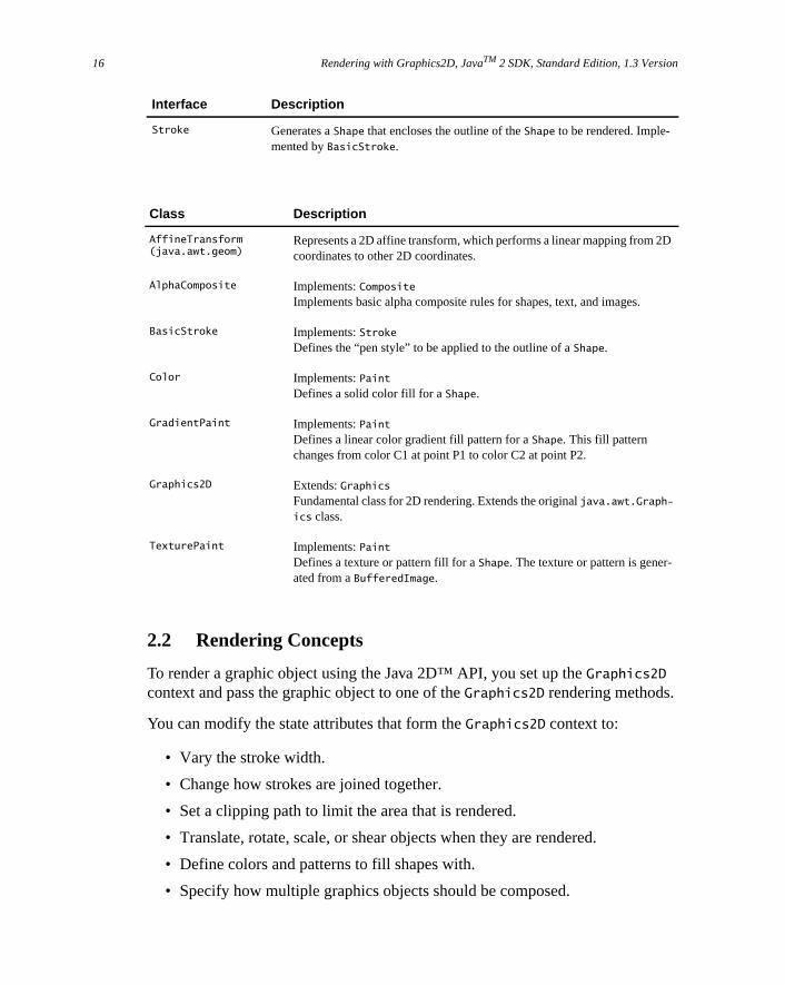
Interface Description
Composite Defines methods to compose a draw primitive with the underlying graphics areImplemented byAlphaComposite.
CompositeContext Defines the encapsulated and optimized environment for a composite operatiUsed by programmers implementing custom compositing rules.
Paint Extends:TransparencyDefines colors for adraw or fill operation. Implemented byColor, Gradient-Paint andTexturePaint.
PaintContext Defines the encapsulated and optimized environment for a paint operation. Usby programmers implementing custom paint operations.
15
Rendering with Graphics2D, JavaTM 2 SDK, Standard Edition, 1.3 Version16
D
2.2 Rendering Concepts
To render a graphic object using the Java 2D™ API, you set up theGraphics2D
context and pass the graphic object to one of theGraphics2D rendering methods.
You can modify the state attributes that form theGraphics2D context to:
• Vary the stroke width.
• Change how strokes are joined together.
• Set a clipping path to limit the area that is rendered.
• Translate, rotate, scale, or shear objects when they are rendered.
• Define colors and patterns to fill shapes with.
• Specify how multiple graphics objects should be composed.
Stroke Generates aShape that encloses the outline of theShape to be rendered. Imple-mented byBasicStroke.
Class Description
AffineTransform(java.awt.geom)
Represents a 2D affine transform, which performs a linear mapping from 2coordinates to other 2D coordinates.
AlphaComposite Implements:CompositeImplements basic alpha composite rules for shapes, text, and images.
BasicStroke Implements:StrokeDefines the “pen style” to be applied to the outline of aShape.
Color Implements:PaintDefines a solid color fill for aShape.
GradientPaint Implements:PaintDefines a linear color gradient fill pattern for aShape. This fill patternchanges from color C1 at point P1 to color C2 at point P2.
Graphics2D Extends:GraphicsFundamental class for 2D rendering. Extends the originaljava.awt.Graph-
ics class.
TexturePaint Implements:PaintDefines a texture or pattern fill for aShape. The texture or pattern is gener-ated from aBufferedImage.
Interface Description
Rendering Concepts 17
eicular
ssi-
ationy.
to
s
er-
ce.
ash as
Graphics2D defines several methods for adding and changing attributes in thgraphics context. Most of these methods take an object that represents a partattribute, such as aPaint or Stroke object.
TheGraphics2D context holdsreferences to these attribute objects: they are notcloned. If you alter an attribute object that is part of theGraphics2D context, youneed to call the appropriateset method to notify the context. Modifying anattribute object during a rendering operation will cause unpredictable and pobly unstable behavior.
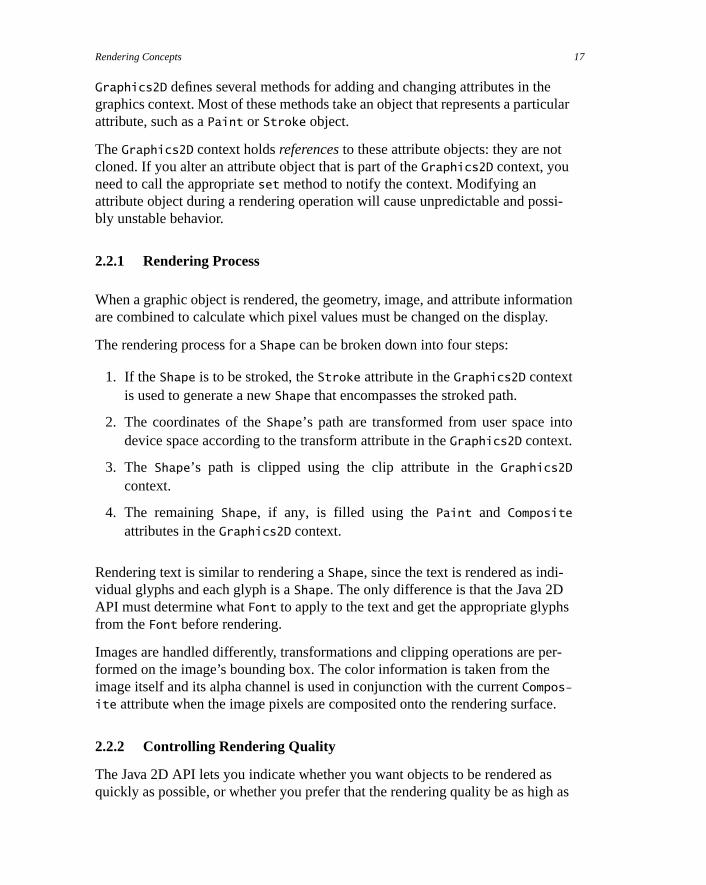
2.2.1 Rendering Process
When a graphic object is rendered, the geometry, image, and attribute informare combined to calculate which pixel values must be changed on the displa
The rendering process for aShape can be broken down into four steps:
1. If theShape is to be stroked, theStroke attribute in theGraphics2D contextis used to generate a newShape that encompasses the stroked path.
2. The coordinates of theShape’s path are transformed from user space indevice space according to the transform attribute in theGraphics2D context.
3. The Shape’s path is clipped using the clip attribute in theGraphics2Dcontext.
4. The remainingShape, if any, is filled using thePaint and Composite
attributes in theGraphics2D context.
Rendering text is similar to rendering aShape, since the text is rendered as indi-vidual glyphs and each glyph is aShape. The only difference is that the Java 2DAPI must determine whatFont to apply to the text and get the appropriate glyphfrom theFont before rendering.
Images are handled differently, transformations and clipping operations are pformed on the image’s bounding box. The color information is taken from theimage itself and its alpha channel is used in conjunction with the currentCompos-
ite attribute when the image pixels are composited onto the rendering surfa
2.2.2 Controlling Rendering Quality
The Java 2D API lets you indicate whether you want objects to be rendered quickly as possible, or whether you prefer that the rendering quality be as hig

Rendering with Graphics2D, JavaTM 2 SDK, Standard Edition, 1.3 Version18
ll be
possible. Your preferences are specified as hints through theRenderingHints
attribute in theGraphics2D context. Not all platforms support modification of therendering mode so specifying rendering hints does not guarantee that they wiused.
TheRenderingHints class supports the following types of hints:
• Alpha interpolation—can be set to default, quality, or speed.
• Antialiasing—can be set to default, on, or off.
• Color Rendering–can be set to default, quality, or speed.
• Dithering—can be set to default, disable, or enable.
• Fractional Metrics—can be set to default, on, or off.
• Interpolation—can be set to nearest-neighbor, bilinear, or bicubic.
• Rendering—can be set to default, quality, or speed.
• Text antialiasing—can be set to default, on, or off.
To set or change theRenderingHints attribute in theGraphics2D context, youcall setRenderingHints. When a hint is set to default, the platform renderingdefault is used is used.

Rendering Concepts 19
le,
their
thatw-
ve,
s theal
2.2.3 Stroke Attributes
Stroking aShape such as aGeneralPath object is equivalent to running a logicalpen along the segments of theGeneralPath. TheGraphics2D Stroke attributedefines the characteristics of the mark drawn by the pen.
A BasicStroke object is used to define the stroke attributes for aGraphics2D
context.BasicStroke defines characteristics such as the line width, endcap stysegment join-style, and the dashing pattern. To set or change theStroke attributein theGraphics2D context, you callsetStroke.
Figure 2-1 endcap styles supported byBasicStroke
Antialiasing
When graphics primitives are rendered on raster-graphics display devices, edges can appear jagged because ofaliasing. Arcs and diagonal lines take on ajagged appearance because they are approximated by turning on the pixelsare closest to the path of the line or curve. This is particularly noticeable on loresolution devices, where the jagged edges appear in stark contrast to thesmooth edges of horizontal or vertical lines.
Antialiasing is a technique used to render objects with smoother-appearingedges. Instead of simply turning on the pixel that is closest to the line or curthe intensity of surrounding pixels is set in proportion to the amount of areacovered by the geometry being rendered. This softens the edges and spreadon-off transition over multiple pixels. However, antialiasing requires additioncomputing resources and can reduce rendering speed.
Aliasing Antialiasing
Chopped(CAP_BUTT)
Round(CAP_ROUND)
Squared(CAP_SQUARED)
Rendering with Graphics2D, JavaTM 2 SDK, Standard Edition, 1.3 Version20
d
ed
e
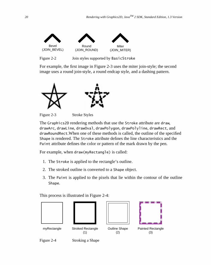
Figure 2-2 Join styles supported byBasicStroke
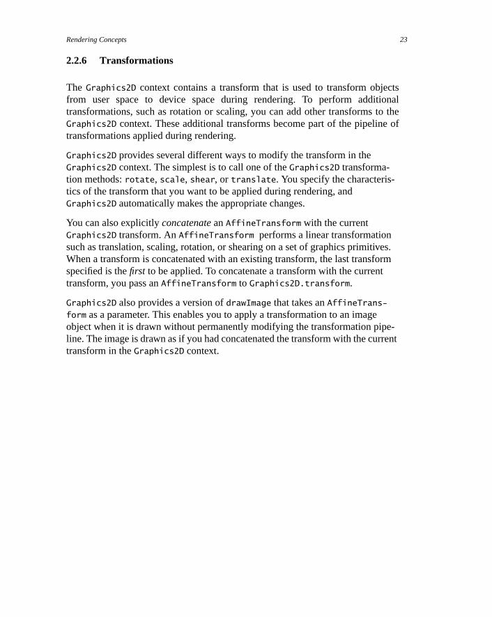
For example, the first image in Figure 2-3 uses the miter join-style; the seconimage uses a round join-style, a round endcap style, and a dashing pattern.
Figure 2-3 Stroke Styles
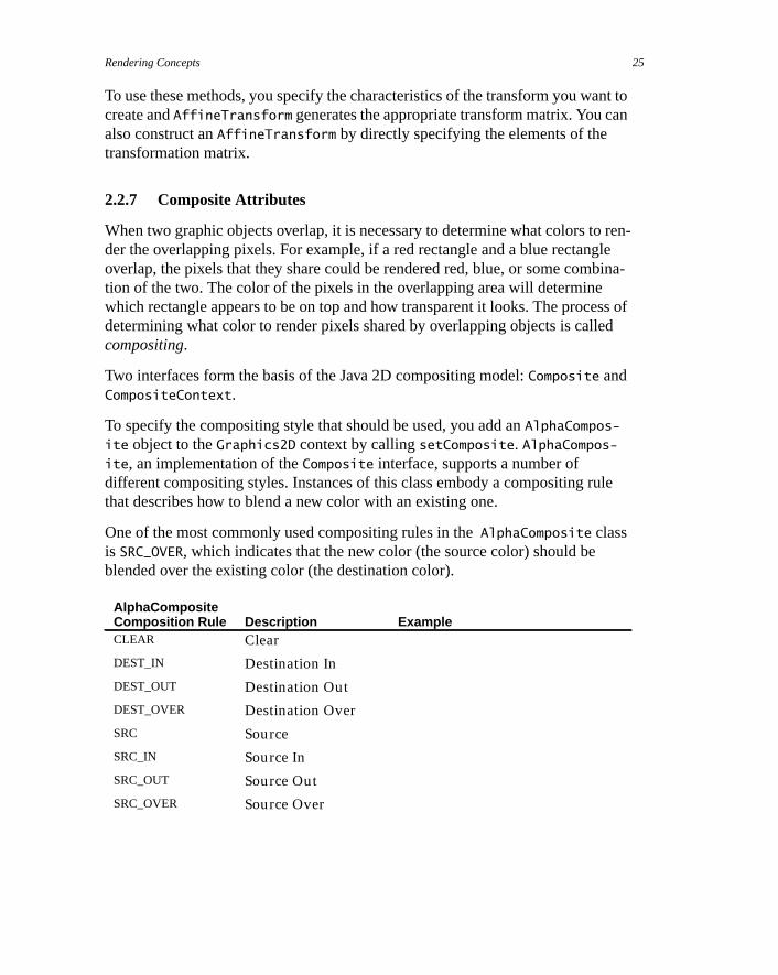
TheGraphics2D rendering methods that use theStroke attribute aredraw,drawArc, drawLine, drawOval, drawPolygon, drawPolyline, drawRect, anddrawRoundRect.When one of these methods is called, the outline of the specifiShape is rendered. TheStroke attribute defines the line characteristics and thePaint attribute defines the color or pattern of the mark drawn by the pen.
For example, whendraw(myRectangle) is called:
1. TheStroke is applied to the rectangle’s outline.
2. The stroked outline is converted to aShape object.
3. ThePaint is applied to the pixels that lie within the contour of the outlinShape.
This process is illustrated in Figure 2-4:
Figure 2-4 Stroking a Shape
Bevel(JOIN_BEVEL)
Round(JOIN_ROUND)
Miter(JOIN_MITER)
myRectangle Stroked Rectangle(1)
Outline Shape(2)
���������
yyyyyyyyy
Painted Rectangle(3)

Rendering Concepts 21
you
-
2.2.4 Fill Attributes
The fill attribute in theGraphics2D context is represented by aPaint object. Youadd aPaint to theGraphics2D context by callingsetPaint.
When aShape or glyph is drawn (Graphics2D.draw, Graphics2D.drawString),thePaint is applied to all of the pixels that lie inside of theShape that representsthe object’s stroked outline. When aShape is filled (Graphics2D.fill), thePaint is applied to all of the pixels that lie within theShape’s contour.
Simple solid color fills can be set with thesetColor method.Color is the sim-plest implementation of thePaint interface.
To fill Shapes with more complex paint styles such as gradients and textures,use the Java 2DPaint classesGradientPaint andTexturePaint. These classeseliminate the time-consuming task of creating complex fills using simple solidcolor paints. Figure 2-5 illustrates two fills that could easily be defined byGradi-
entPaint andTexturePaint.
Figure 2-5 Complex Fill Styles
Whenfill is called to render aShape, the system:
1. Determines what pixels comprise theShape.
2. Gets the color of each pixel from thePaint object.
3. Converts the color to an appropriate pixel value for the output device.
4. Writes the pixel to that device.
������������QQRRSSSSTTTT¢¢££¤¤¤¤¥¥¥¥

Rendering with Graphics2D, JavaTM 2 SDK, Standard Edition, 1.3 Version22
th
or a
rateethem
extur-
2.2.5 Clipping Paths
A clipping path identifies the portion of aShape or Image that needs to berendered. When a clipping path is part of theGraphics2D context, only thoseparts of aShape or Image that lie within the path are rendered.
To add a clipping path to theGraphics2D context, you callsetClip. Any Shape
can be used to define the clipping path.
To change the clipping path, you can either usesetClip to specify a new path orcall clip to change the clipping path to the intersection of the old clipping paand a newShape.
Batch Processing
To streamline the processing of pixels, the Java 2D API processes them inbatches. A batch can be either a contiguous set of pixels on a given scanlineblock of pixels. This batch processing is done in two steps:
1. The Paint object’s createContext method is called to create aPaintContext. ThePaintContext stores the contextual information aboutthe current rendering operation and the information necessary to genethe colors. ThecreateContext method is passed the bounding boxes of thgraphics object being filled in user space and in device space,ColorModel in which the colors should be generated, and the transforused to map user space into device space. TheColorModel is treated as ahint because not allPaint objects can support an arbitraryColorModel.(For more information aboutColorModels, see “Color” on page 89.”)
2. The getColorModel method is called to get theColorModel of thegenerated paint color from thePaintContext.
The getRaster method is then called repeatedly to get theRaster that con-tains the actual color data for each batch. This information is passed to the nstage in the rendering pipeline, which draws the generated color using the crentComposite object.
Rendering Concepts 23
ctsonalo the
of
es.rm
e-rent
2.2.6 Transformations
The Graphics2D context contains a transform that is used to transform objefrom user space to device space during rendering. To perform addititransformations, such as rotation or scaling, you can add other transforms tGraphics2D context. These additional transforms become part of the pipelinetransformations applied during rendering.
Graphics2D provides several different ways to modify the transform in theGraphics2D context. The simplest is to call one of theGraphics2D transforma-tion methods:rotate, scale, shear, ortranslate. You specify the characteris-tics of the transform that you want to be applied during rendering, andGraphics2D automatically makes the appropriate changes.
You can also explicitlyconcatenate anAffineTransform with the currentGraphics2D transform. AnAffineTransform performs a linear transformationsuch as translation, scaling, rotation, or shearing on a set of graphics primitivWhen a transform is concatenated with an existing transform, the last transfospecified is thefirst to be applied. To concatenate a transform with the currenttransform, you pass anAffineTransform to Graphics2D.transform.
Graphics2D also provides a version ofdrawImage that takes anAffineTrans-form as a parameter. This enables you to apply a transformation to an imageobject when it is drawn without permanently modifying the transformation pipline. The image is drawn as if you had concatenated the transform with the curtransform in theGraphics2D context.

Rendering with Graphics2D, JavaTM 2 SDK, Standard Edition, 1.3 Version24
en-
s
s
ng
as
ce
2.2.6.1 Constructing an AffineTransform
AffineTransform provides a set of convenience methods for constructingAffin-
eTransform objects:
• getTranslateInstance
• getRotateInstance
• getScaleInstance
• getShearInstance
Affine Transforms
The Java 2D API provides one transform class,AffineTransform. Affine-Transforms are used to transform text, shapes, and images when they are rdered. You can also apply transforms toFont objects to create new fontderivations, as discussed in “Creating Font Derivations” on page 65.
An affine transformation performs a linear transformation on a set of graphicprimitives. It always transforms straight lines into straight lines and parallellines into parallel lines; however, the distance between points and the anglebetween nonparallel lines might be altered.
Affine transformations are based on two-dimensional matrices of the followiform:
where and
Transforms can be combined, effectively creating a series orpipeline of trans-formations that can be applied to an object. This combination is referred to concatenation. When a transform is concatenated with an existing transform,such as withAffineTransform.concatenate, the last transform specified isthefirst to be applied. A transform can also bepre-concatenated with an exist-ing transform. In this case, the last transform specified is thelast to be applied.
Pre-concatenation is used to perform transformations relative to device spainstead of user space. For example, you could useAffineTransform.preCon-
catenate to perform a translation relative to absolute pixel space.
a c txb d ty
x′ ax cy tx+ += y′ bx dy ty+ +=
Rendering Concepts 25
nt toan
ren-glebina-
ss ofed
le
To use these methods, you specify the characteristics of the transform you wacreate andAffineTransform generates the appropriate transform matrix. You calso construct anAffineTransform by directly specifying the elements of thetransformation matrix.
2.2.7 Composite Attributes
When two graphic objects overlap, it is necessary to determine what colors toder the overlapping pixels. For example, if a red rectangle and a blue rectanoverlap, the pixels that they share could be rendered red, blue, or some comtion of the two. The color of the pixels in the overlapping area will determinewhich rectangle appears to be on top and how transparent it looks. The procedetermining what color to render pixels shared by overlapping objects is callcompositing.
Two interfaces form the basis of the Java 2D compositing model:Composite andCompositeContext.
To specify the compositing style that should be used, you add anAlphaCompos-
ite object to theGraphics2D context by callingsetComposite. AlphaCompos-ite, an implementation of theComposite interface, supports a number ofdifferent compositing styles. Instances of this class embody a compositing ruthat describes how to blend a new color with an existing one.
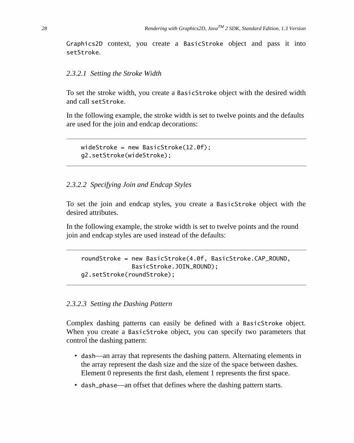
One of the most commonly used compositing rules in theAlphaComposite classis SRC_OVER, which indicates that the new color (the source color) should beblended over the existing color (the destination color).
AlphaCompositeComposition Rule Description ExampleCLEAR Clear
DEST_IN Destination In
DEST_OUT Destination Out
DEST_OVER Destination Over
SRC Source
SRC_IN Source In
SRC_OUT Source Out
SRC_OVER Source Over

Rendering with Graphics2D, JavaTM 2 SDK, Standard Edition, 1.3 Version26
nt-lors
han.
that
for-
for-mple
2.2.7.1 Managing Transparency
A color’s alpha value is a measure of its transparency: it indicates, as a perceage, how much of a previously rendered color should show through when cooverlap. Opaque colors (alpha=1.0) don’t allow any of the underlying color toshow through, while transparent colors (alpha=0.0) let all of it show through.
When text andShapes are rendered, the alpha value is derived from thePaint
attribute in theGraphics2D context. WhenShapes and text are antialiased, thealpha value from thePaint in theGraphics2D context is combined with pixelcoverage information from the rasterized path. Images maintain their own alpinformation—see “Transparency and Images” on page 26 for more informatio
When you construct anAlphaComposite object, you can specify an additionalalpha value. When you add thisAlphaComposite object to theGraphics2D con-text, this extra alpha value increases the transparency of any graphic objectsare rendered—the alpha value of each graphic object is multiplied by theAlpha-
Composite’s alpha value.
2.2.7.2 Transparency and Images
Images can carry transparency information for each pixel in the image. This inmation, called analpha channel, is used in conjunction with theComposite objectin theGraphics2D context to blend the image with existing drawings.
For example, Figure 2-6 contains three images with different transparency inmation. In each case, the image is displayed over a blue rectangle. This exaassumes that theGraphics2D context contains anAlphaComposite object thatusesSRC_OVER as the compositing operation.
Figure 2-6 Transparency and Images

Setting Up the Graphics2D Context 27
lly sec-on-ird
the
w
ithm
e is
thethe
In the first image, all of the pixels are either fully opaque (the dog’s body) or futransparent (the background). This effect is often used on Web pages. In theond image, all of the pixels in the dog’s body are rendered using a uniform, nopaque alpha value, allowing the blue background to show through. In the thimage, the pixels around the dogs face are fully opaque (alpha=1.0), but as distance from its face increases, the alpha values for the pixels decrease.
2.3 Setting Up the Graphics2D Context
To configure theGraphics2D context for rendering, you use theGraphics2D setmethods to specify attributes such as theRenderingHints, Stroke, Paint,clipping path,Composite, andTransform.
2.3.1 Setting Rendering Hints
A RenderingHints object encapsulates all of your preferences concerning hoan object is rendered. To set the rendering hints in theGraphics2D context, youcreate aRenderingHints object and pass it intoGraphics2D.setRendering-Hints.
Setting a rendering hint does not guarantee that a particular rendering algorwill be used: not all platforms support modification of the rendering mode.
In the following example, antialiasing is enabled and the rendering preferencset to quality:
qualityHints = new RenderingHints(RenderingHints.KEY_ANTIALIASING, RenderingHints.VALUE_ANTIALIAS_ON);qualityHints.put(RenderingHints.KEY_RENDERING, RenderingHints.VALUE_RENDER_QUALITY);g2.setRenderingHints(qualityHints);
2.3.2 Specifying Stroke Attributes
A BasicStroke defines the characteristics applied to aShape’s outline, includingits width and dashing pattern, how line segments are joined together, anddecoration (if any) applied to the end of a line. To set the stroke attributes in
Rendering with Graphics2D, JavaTM 2 SDK, Standard Edition, 1.3 Version28
lts
d
at
s inhes..
Graphics2D context, you create aBasicStroke object and pass it intosetStroke.
2.3.2.1 Setting the Stroke Width
To set the stroke width, you create aBasicStroke object with the desired widthand callsetStroke.
In the following example, the stroke width is set to twelve points and the defauare used for the join and endcap decorations:
wideStroke = new BasicStroke(12.0f);g2.setStroke(wideStroke);
2.3.2.2 Specifying Join and Endcap Styles
To set the join and endcap styles, you create aBasicStroke object with thedesired attributes.
In the following example, the stroke width is set to twelve points and the rounjoin and endcap styles are used instead of the defaults:
roundStroke = new BasicStroke(4.0f, BasicStroke.CAP_ROUND, BasicStroke.JOIN_ROUND);g2.setStroke(roundStroke);
2.3.2.3 Setting the Dashing Pattern
Complex dashing patterns can easily be defined with aBasicStroke object.When you create aBasicStroke object, you can specify two parameters thcontrol the dashing pattern:
• dash—an array that represents the dashing pattern. Alternating elementthe array represent the dash size and the size of the space between dasElement 0 represents the first dash, element 1 represents the first space
• dash_phase—an offset that defines where the dashing pattern starts.

Setting Up the Graphics2D Context 29
Ine sec-
rawne
n
t of
geswo
In the following example, two different dashing patterns are applied to a line.the first, the size of the dashes and the space between them is constant. Thond dashing pattern is more complex, using a six-element array to define thedashing pattern.
float dash1[] = {10.0f};BasicStroke bs = new BasicStroke(5.0f, BasicStroke.CAP_BUTT, BasicStroke.JOIN_MITER, 10.0f, dash1, 0.0f);g2.setStroke(bs);Line2D line = new Line2D.Float(20.0f, 10.0f, 100.0f, 10.0f);g2.draw(line);
float[] dash2 = {6.0f, 4.0f, 2.0f, 4.0f, 2.0f, 4.0f};bs = new BasicStroke(5.0f, BasicStroke.CAP_BUTT, BasicStroke.JOIN_MITER, 10.0f, dash2, 0.0f);g2.setStroke(bs);g2.draw(line);
Both dashing patterns use a dash phase of zero, causing the dashes to be dstarting at the beginning of the dashing pattern. The two dashing patterns arshown in Figure Figure 2-7.
Figure 2-7 Dashing Patterns
2.3.3 Specifying Fill Attributes
ThePaint attribute in theGraphics2D context determines the fill color or patterthat is used when text andShapes are rendered.
2.3.3.1 Filling a Shape with a Gradient
TheGradientPaint class provides an easy way to fill a shape with a gradienone color to another. When you create aGradientPaint, you specify a beginningposition and color, and an ending position and color. The fill color chanproportionally from one color to the other along the line connecting the tpositions, as shown in Figure 2-8.

Rendering with Graphics2D, JavaTM 2 SDK, Standard Edition, 1.3 Version30
tsthe
ing
tition
Figure 2-8 Creating Gradient Fills
In the third star in Figure 2-8, both points lie within the shape. All of the poinalong the gradient line extending beyond P1 take the beginning color, andpoints along the gradient line extending beyond P2 take the ending color.
To fill a shape with a gradient of one color to another:
1. Create aGradientPaint object.
2. CallGraphics2D.setPaint.
3. Create theShape.
4. CallGraphics2D.fill(shape).
In the following example, a rectangle is filled with a blue-green gradient.
GradientPaint gp = new GradientPaint(50.0f, 50.0f, Color.blue 50.0f, 250.0f, Color.green);g2.setPaint(gp);g2.fillRect(50, 50, 200, 200);
2.3.3.2 Filling a Shape with a Texture
The TexturePaint class provides an easy way to fill a shape with a repeatpattern. When you create aTexturePaint, you specify aBufferedImage to useas the pattern. You also pass the constructor a rectangle to define the repefrequency of the pattern, as shown in Figure 2-9.
P1 P2
P1
P2
P1 P2

Setting Up the Graphics2D Context 31
a
Figure 2-9 Creating Texture Paints
To fill a shape with a texture:
1. Create aTexturePaint object.
2. CallGraphics2D.setPaint.
3. Create theShape.
4. CallGraphics2D.fill(shape).
In the following example, a rectangle is filled with a simple texture created frombuffered image.
// Create a buffered image texture patch of size 5x5BufferedImage bi = new BufferedImage(5, 5, BufferedImage.TYPE_INT_RGB);Graphics2D big = bi.createGraphics();// Render into the BufferedImage graphics to create the texturebig.setColor(Color.green);big.fillRect(0,0,5,5);big.setColor(Color.lightGray);big.fillOval(0,0,5,5);
// Create a texture paint from the buffered imageRectangle r = new Rectangle(0,0,5,5);TexturePaint tp = newTexturePaint(bi,r,TexturePaint.NEAREST_NEIGHBOR);
// Add the texture paint to the graphics context.g2.setPaint(tp);
// Create and render a rectangle filled with the texture.
Pattern Image Rectangle Defining Repetition Frequency
Large Rectangle Filled with Resulting TexturePaint

Rendering with Graphics2D, JavaTM 2 SDK, Standard Edition, 1.3 Version32
e
nt
od-
g2.fillRect(0,0,200,200);}
2.3.4 Setting the Clipping Path
To define a clipping path:
1. Create aShape that represents the area you want to render.
2. Call Graphics2D.setClip to use the shape as the clipping path for thGraphics2D context.
To shrink the clipping path:
1. Create aShape that intersects the current clipping path.
2. Call clip to change the clipping path to the intersection of the curreclipping path and the newShape.
In the following example, a clipping path is created from an ellipse and then mified by callingclip.
public void paint(Graphics g) { Graphics2D g2 = (Graphics2D) g;
// The width and height of the canvas int w = getSize().width; int h = getSize().height; // Create an ellipse and use it as the clipping path Ellipse2D e = new Ellipse2D.Float(w/4.0f,h/4.0f, w/2.0f,h/2.0f); g2.setClip(e);
// Fill the canvas. Only the area within the clip is rendered g2.setColor(Color.cyan); g2.fillRect(0,0,w,h);
// Change the clipping path, setting it to the intersection of // the current clip and a new rectangle. Rectangle r = new Rectangle(w/4+10,h/4+10,w/2-20,h/2-20); g2.clip(r);

Setting Up the Graphics2D Context 33
n-
// Fill the canvas. Only the area within the new clip // is rendered g2.setColor(Color.magenta); g2.fillRect(0,0,w,h);}
2.3.5 Setting the Graphics2D Transform
To transform aShape, text string, orImage you add a newAffineTransform tothe transformation pipeline in theGraphics2D context before rendering. Thetransformation is applied when the graphic object is rendered.
For example, to draw a rectangle that is rotated 45 degrees:
1. Get a rotation transform by callingAffineTransform. getRotateInstance.
2. Call Graphics2D.setTransform to add the new transform to thetransformation pipeline.
3. Create aRectangle2D.Float object.
4. Call Graphics2D.draw to render the rectangle.
In the following example, an instance ofAffineTransform is used to rotate arectangle 45 degrees when it is rendered.
Rectangle2D rect = new Rectangle2D.Float(1.0,1.0,2.0,3.0);AffineTransform rotate45 = AffineTransform.getRotateInstance(Math.PI/4.0,0.0,0.0)g2.setTransform(rotate45);g2.draw(rect);
In this example, anAffineTransform is used to rotate a text string around a ceter point:
// Define the rendering transformAffineTransform at = new AffineTransform();// Apply a translation transform to make room for the// rotated text.at.setToTranslation(400.0, 400.0);g2.transform(at);

Rendering with Graphics2D, JavaTM 2 SDK, Standard Edition, 1.3 Version34
ing
orssition
ionle, ifrlapslast
// Create a rotation transform to rotate the textat.setToRotation(Math.PI / 2.0);// Render four copies of the string “Java” at 90 degree anglesfor (int i = 0; i < 4; i++) { g2.drawString(“Java”, 0.0f, 0.0f); g2.transform(at);}
You can transform an image in the same way—the transform in theGraphics2D
context is applied during rendering regardless of the type of graphic object berendered.
To apply a transform to an imagewithout changing the transform in theGraphics2D context, you can pass anAffineTransform to drawImage:
AffineTransform rotate45 = AffineTransform.getRotateInstance(Math.PI/4.0,0.0,0.0)g2.drawImage(myImage, rotate45);
Transforms can also be applied to aFont to create a modified version of theFont, for more information see “Creating Font Derivations” on page 65.
2.3.6 Specifying a Composition Style
An AlphaComposite encapsulates composition rules that determine how colshould be rendered when one object overlaps another. To specify the compostyle for theGraphics2D context, you create anAlphaComposite and pass it intosetComposite. The most commonly used is composition style isSRC_OVER.
2.3.6.1 Using the Source Over Compositing Rule
TheSRC_OVER compositing rule composites the source pixel over the destinatpixel such that the shared pixel takes the color of the source pixel. For exampyou render a blue rectangle and then render a red rectangle that partially oveit, the overlapping area will be red. In other words, the object that is renderedwill appear to be on top.
To use theSRC_OVER composition rule:
1. Create anAlphaComposite object by callinggetInstance and specifying the

Setting Up the Graphics2D Context 35
the
t is
ct
ano be
SRC_OVER rule.
AlphaComposite ac =AlphaComposite.getInstance(AlphaComposite.SRC_OVER);
2. Call setComposite to add theAlphaComposite object to theGraphics2Dcontext.
g2.setComposite(ac);
Once the composite object is set, overlapping objects will be rendered usingspecified composition rule.
2.3.6.2 Increasing the Transparency of Composited Objects
AlphaComposite allows you to specify an additional constant alpha value thamultiplied with the alpha of the source pixels to increase transparency.
For example, to create anAlphaComposite object that renders the source obje50% transparent, specify an alpha of .5:
AlphaComposite ac =AlphaComposite.getInstance(AlphaComposite.SRC_OVER, .5f);
In the following example, a source over alpha composite object is created withalpha of .5 and added to the graphics context, causing subsequent shapes trendered 50% transparent.
public void paint(Graphics g) { Graphics2D g2 = (Graphics2D) g;
g2.setColor(Color.red); g2.translate(100,50); // radians=degree * pie / 180 g2.rotate((45*java.lang.Math.PI)/180); g2.fillRect(0,0,100,100); g2.setTransform(new AffineTransform()); // set to identity // Create a new alpha composite AlphaComposite ac =
AlphaComposite.getInstance(AlphaComposite.SRC_OVER,0.5f); g2.setComposite(ac); g2.setColor(Color.green); g2.fillRect(50,0,100,100);

Rendering with Graphics2D, JavaTM 2 SDK, Standard Edition, 1.3 Version36
he
lso
.)
g2.setColor(Color.blue); g2.fillRect(125,75,100,100); g2.setColor(Color.yellow); g2.fillRect(50,125,100,100); g2.setColor(Color.pink); g2.fillRect(-25,75,100,100);}
2.4 Rendering Graphics Primitives
Graphics2D provides rendering methods forShapes, Text, andImages:
• draw—strokes aShape’s path using theStroke andPaint objects in theGraphics2D context.
• fill—fills a Shape using thePaint in theGraphics2D context.
• drawString—renders the specified text string using thePaint in theGraphics2D context.
• drawImage—renders the specified image.
To stroke and fill a shape, you must call both thedraw andfill methods.
Graphics2D also supports the draw and fill methods from previous versions of tJDK software, such asdrawOval andfillRect.
2.4.1 Drawing a Shape
The outline of anyShape can be rendered with theGraphics2D.draw method.The draw methods from previous versions of the JDK software are asupported: drawLine, drawRect, drawRoundRect, drawOval, drawArc,drawPolyline, drawPolygon, draw3DRect.
When aShape is drawn, its path is stroked with theStroke object in theGraphics2D context. (See “Stroke Attributes” on page 19 for more informationBy setting an appropriateBasicStroke object in theGraphics2D context, youcan draw lines of any width or pattern. TheBasicStroke object also defines theline’s endcap and join attributes.
To render shape’s outline:
1. Create aBasicStroke object
Rendering Graphics Primitives 37
ted:
2. CallGraphics2D.setStroke
3. Create theShape.
4. CallGraphics2D.draw(shape).
In the following example, aGeneralPath object is used to define a star and aBasicStroke object is added to theGraphics2D context to define the star’s linewith and join attributes.
public void paint(Graphics g) { Graphics2D g2 = (Graphics2D) g;
// create and set the stroke g2.setStroke(new BasicStroke(4.0f));
// Create a star using a general path object GeneralPath p = new GeneralPath(GeneralPath.NON_ZERO); p.moveTo(- 100.0f, - 25.0f); p.lineTo(+ 100.0f, - 25.0f); p.lineTo(- 50.0f, + 100.0f); p.lineTo(+ 0.0f, - 100.0f); p.lineTo(+ 50.0f, + 100.0f); p.closePath();
// translate origin towards center of canvas g2.translate(100.0f, 100.0f);
// render the star's path g2.draw(p);}
2.4.2 Filling a Shape
The Graphics2D.fill method can be used tofill anyShape. When aShape isfilled, the area within its path is rendered with theGraphics2D context’s currentPaint attribute—aColor, TexturePaint, orGradientPaint.
The fill methods from previous versions of the JDK software are also supporfillRect, fill3DRect, fillRoundRect, fillOval, fillArc, fillPolygon,clearRect.
To fill a Shape:
Rendering with Graphics2D, JavaTM 2 SDK, Standard Edition, 1.3 Version38
ting
g
os-
1. Set the fill color or pattern on the graphics context usingGraphics2D.setColor or Graphics2D.setPaint.
1. Create theShape.
2. CallGraphics2D.fill to render theShape.
In the following example,setColor is called to define a green fill for aRectangle2D.
public void paint(Graphics g) { Graphics2D g2 = (Graphics2D) g;
g2.setPaint(Color.green); Rectangle2D r2 = new Rectangle2D.Float(25,25,150,150);
g2.fill(r2);}
2.4.3 Rendering Text
To render a text string, you callGraphics2D.drawString, passing in the stringthat you want to render. For more information about rendering text and selecfonts, see “Fonts and Text Layout” on page 45.
2.4.4 Rendering Images
To render anImage, you create theImage and call Graphics2D.drawImage. Formore information about processing and rendering images, see “Imaging” onpage 67.
2.5 Defining Custom Composition Rules
You can create an entirely new type of compositing operation by implementintheComposite andCompositeContext interfaces. AComposite object provides aCompositeContext object that actually holds the state and performs the compiting work. MultipleCompositeContext objects can be created from oneCompos-ite object to maintain the separate states in a multithreaded environment.
Rendering in a Multi-Screen Environment 39
by a
ther
ual
natertual
vi-tualtual
2.6 Rendering in a Multi-Screen Environment
With the release of the JavaTM 2 SDK, version 1.3, the Java 2DTM API supportsthree different multi-screen configurations that can possibly be configurednative platform:
• Two or more independent screens
• Two or more screens where one screen is the primary screen and the oscreens display copies of what appears on the primary screen.
• Two or more screens that form a virtual desktop, which is also called a virtdevice.
The Java 2D API enables you to createFrame, JFrame, Window, orJWindowobjects with aGraphicsConfiguration to target a screen device for rendering.
In all three configurations, each screen device is represented by aGraphicsDe-
vice. A GraphicsDevice can have multipleGraphicsConfiguration objectsassociated with it.
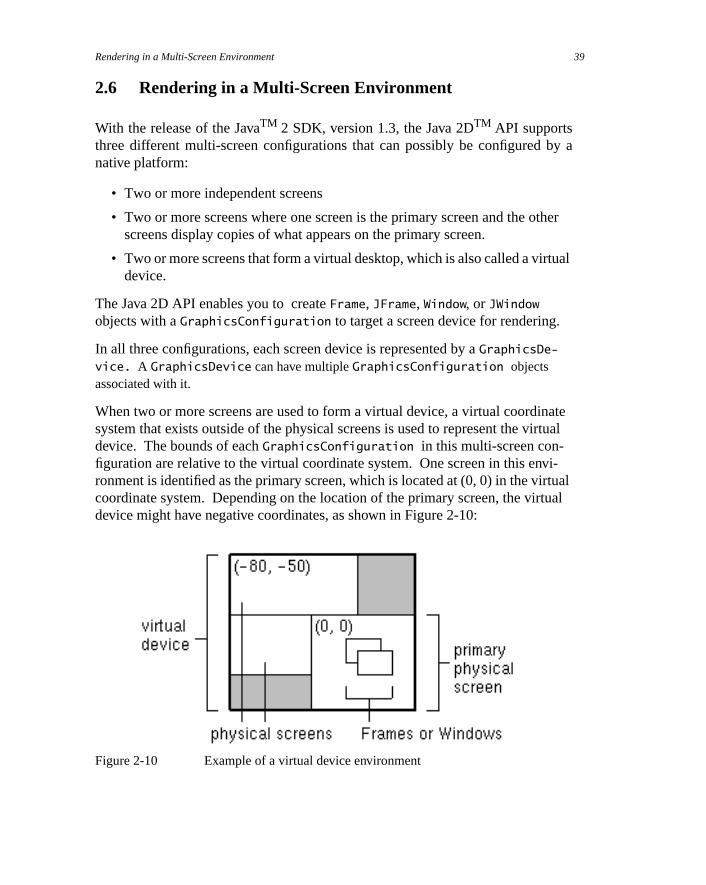
When two or more screens are used to form a virtual device, a virtual coordisystem that exists outside of the physical screens is used to represent the videvice. The bounds of eachGraphicsConfiguration in this multi-screen con-figuration are relative to the virtual coordinate system. One screen in this enronment is identified as the primary screen, which is located at (0, 0) in the vircoordinate system. Depending on the location of the primary screen, the virdevice might have negative coordinates, as shown in Figure 2-10:
Figure 2-10 Example of a virtual device environment
Rendering with Graphics2D, JavaTM 2 SDK, Standard Edition, 1.3 Version40
-
e
oor-
-
dif-
al
ds.
To determine if your environment is a virtual device environment in which aWin-
dow or aFrame can span two or more physical screens, callgetBounds on eachGraphicsConfiguration in your system and check to see if the origin is something other than (0, 0). ThegetBounds method of aGraphicsConfigurationreturns aRectangle in the virtual coordinate system. So, if any of the origins arnot (0, 0), your environment is a virtual device environment.
In a virtual device environment, the coordinates of theGraphicsConfiguration
objects are relative to the virtual coordinate system. So, you must use virtual cdinates when calling thesetLocation method of aFrame or Window. For exam-ple, this code sample gets the bounds of aGraphicsConfiguration and uses thebounds to set the location of aFrame at (10, 10) relative to the origin of the physical screen of the correspondingGraphicsConfiguration.
Frame f = new Frame(GraphicsConfiguration gc);Rectangle bounds = gc.getBounds();f.setLocation(10 + bounds.x, 10 + bounds.y);
If the bounds of theGraphicsConfiguration are not taken into account, theFrame is displayed at (10, 10) on the primary physical screen, which might beferent from the physical screen of the specifiedGraphicsConfiguration.
ThegetBounds method can also be used to determine the bounds of the virtudevice. CallgetBounds on eachGraphicsConfiguration in your system. Todetermine the bounds of the virtual device, calculate the union of all the bounThis technique is used in the following sample.
Rectangle virtualBounds = new Rectangle();GraphicsEnvironment ge = GraphicsEnvironment.getLocalGraphicsEnvironment();GraphicsDevice[] gs = ge.getScreenDevices();for (int j = 0; j < gs.length; j++) { GraphicsDevice gd = gs[j]; GraphicsConfiguration[] gc = gd.getConfigurations(); for (int i = 0; i < gc.length; i++) { virtualBounds = virtualBounds.union(gc[i].getBounds()); }}

Rendering in a Multi-Screen Environment 41
The following applet creates aJFrame with everyGraphicsConfiguration ofeveryGraphicsDevice in theGraphicsEnvironment. EachJFrame displays aset of red, green and blue stripes, the screen number, theGraphicsConfigura-
tion number and the bounds of theGraphicsConfiguration. This code samplemust be run with the JavaTM 2 SDK, version 1.3 or later.
import java.applet.Applet;import java.awt.*;import javax.swing.*;
public class MultiFrameApplet extends Applet {
public MultiFrameApplet() { main(null); }
public static void main(String[] argv) { GraphicsEnvironment ge = GraphicsEnvironment.getLocalGraphicsEnvironment(); GraphicsDevice[] gs = ge.getScreenDevices(); for (int j = 0; j < gs.length; j++) { GraphicsDevice gd = gs[j]; GraphicsConfiguration[] gc = gd.getConfigurations(); for (int i=0; i < gc.length; i++) { JFrame f = new JFrame(gs[j].getDefaultConfiguration()); GCCanvas c = new GCCanvas(gc[i]); Rectangle gcBounds = gc[i].getBounds(); int xoffs = gcBounds.x; int yoffs = gcBounds.y; f.getContentPane().add(c); f.setTitle("Screen# "+Integer.toString(j)+", GC# "+Integer.toString(i)); f.setSize(300, 150); f.setLocation((i*50)+xoffs, (i*60)+yoffs); f.show(); } } }}
class GCCanvas extends Canvas {

Rendering with Graphics2D, JavaTM 2 SDK, Standard Edition, 1.3 Version42
GraphicsConfiguration gc; Rectangle bounds;
public GCCanvas(GraphicsConfiguration gc) { super(gc); this.gc = gc; bounds = gc.getBounds(); }
public Dimension getPreferredSize() { return new Dimension(300, 150); }
public void paint(Graphics g) { g.setColor(Color.red); g.fillRect(0, 0, 100, 150); g.setColor(Color.green); g.fillRect(100, 0, 100, 150); g.setColor(Color.blue); g.fillRect(200, 0, 100, 150); g.setColor(Color.black); g.drawString("ScreenSize="+ Integer.toString(bounds.width)+ "X"+ Integer.toString(bounds.height), 10, 15); g.drawString(gc.toString(), 10, 30); }}

3
etriclasses
h as
ny
ese
y
ath
Geometries
The Java 2D™ API provides several classes that define common geomobjects, such as points, lines, curves, and rectangles. These new geometry care part of the java.awt.geom package. For backward compatibility, thegeometry classes that existed in previous versions of the JDK software, sucRectangle, Point, andPolygon, remain in thejava.awt package.
The Java 2D API geometries such asGeneralPath, Arc2D, and Rectangle2D
implement theShape interface defined injava.awt. Shape providesa common
protocol for describing and inspecting geometric path objects. A new interface,PathIterator, defines methods for retrieving elements from a geometry.
Using the geometry classes, you can easily define and manipulate virtually atwo-dimensional object.
3.1 Interfaces and Classes
The following tables list the key geometry interfaces and classes. Most of thinterfaces and classes are part of thejava.awt.geom package. Some, likeShape,are part of thejava.awt package, primarily to maintain backward compatibilitwith earlier versions of the JDK software.
Interface Description
PathIterator Defines methods for retrieving elements from a path.
Shape(java.awt)
Provides a common set of methods for describing and inspecting geometric pobjects. Implemented byGeneralPath and other geometry classes.
39
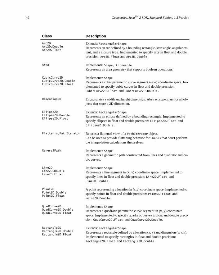
Geometries, JavaTM 2 SDK, Standard Edition, 1.3 Version40
ex-le
Im-
b-
to
cu-
to
ci-
).
Class Description
Arc2DArc2D.DoubleArc2D.Float
Extends:RectangularShapeRepresents an arc defined by a bounding rectangle, start angle, angulartent, and a closure type. Implemented to specify arcs in float and doubprecision:Arc2D.Float andArc2D.Double.
Area Implements:Shape, CloneableRepresents an area geometry that supports boolean operations.
CubicCurve2DCubicCurve2D.DoubleCubicCurve2D.Float
Implements:ShapeRepresents a cubic parametric curve segment in (w) coordinate space.plemented to specify cubic curves in float and double precision:CubicCurve2D.Float andCubicCurve2D.Double.
Dimension2D Encapsulates a width and height dimension. Abstract superclass for all ojects that store a 2D dimension.
Ellipse2DEllipse2D.DoubleEllipse2D.Float
Extends:RectangularShapeRepresents an ellipse defined by a bounding rectangle. Implemented specify ellipses in float and double precision:Ellipse2D.Float andEllipse2D.Double.
FlatteningPathIterator Returns a flattened view of aPathIterator object.Can be used to provide flattening behavior forShapes that don’t performthe interpolation calculations themselves.
GeneralPath Implements:ShapeRepresents a geometric path constructed from lines and quadratic andbic curves.
Line2DLine2D.DoubleLine2D.Float
Implements:ShapeRepresents a line segment in (x, y) coordinate space. Implemented tospecify lines in float and double precision:Line2D.Float andLine2D.Double.
Point2DPoint2D.DoublePoint2D.Float
A point representing a location in (x,y) coordinate space. Implementedspecify points in float and double precision:Point2D.Float andPoint2D.Double.
QuadCurve2DQuadCurve2D.DoubleQuadCurve2D.Float
Implements:ShapeRepresents a quadratic parametric curve segment in (x, y) coordinatespace. Implemented to specify quadratic curves in float and double presion:QuadCurve2D.Float andQuadCurve2D.Double.
Rectangle2DRectangle2D.DoubleRectangle2D.Float
Extends:RectangularShapeRepresents a rectangle defined by a location (x, y) and dimension (w x hImplemented to specify rectangles in float and double precision:Rectangle2D.Float andRectangle2D.Double.
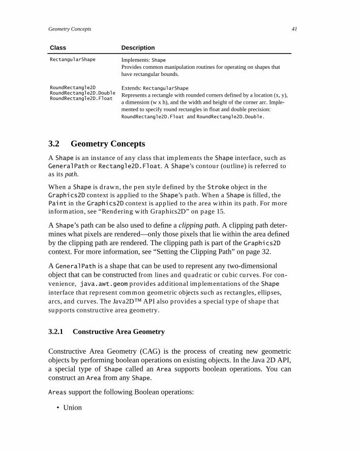
Geometry Concepts 41
ned
l
etricAPI,n
y),-
3.2 Geometry Concepts
A Shape is an instance of any class that implements the Shape interface, such as
GeneralPath or Rectangle2D.Float. A Shape’s contour (outline) is referred to
as its path.
When a Shape is drawn, the pen style defined by the Stroke object in the
Graphics2D context is applied to the Shape’s path. When a Shape is filled, the
Paint in the Graphics2D context is applied to the area within its path. For more
information, see “Rendering with Graphics2D” on page 15.
A Shape’s path can be also used to define aclipping path. A clipping path deter-mines what pixels are rendered—only those pixels that lie within the area defiby the clipping path are rendered. The clipping path is part of theGraphics2D
context. For more information, see “Setting the Clipping Path” on page 32.
A GeneralPath is a shape that can be used to represent any two-dimensionaobject that can be constructed from lines and quadratic or cubic curves. For con-
venience, java.awt.geom provides additional implementations of the Shape
interface that represent common geometric objects such as rectangles, ellipses,
arcs, and curves. The Java2D™ API also provides a special type of shape that
supports constructive area geometry.
3.2.1 Constructive Area Geometry
Constructive Area Geometry (CAG) is the process of creating new geomobjects by performing boolean operations on existing objects. In the Java 2Da special type ofShape called anArea supports boolean operations. You caconstruct anArea from anyShape.
Areas support the following Boolean operations:
• Union
RectangularShape Implements:ShapeProvides common manipulation routines for operating on shapes thathave rectangular bounds.
RoundRectangle2DRoundRectangle2D.DoubleRoundRectangle2D.Float
Extends:RectangularShapeRepresents a rectangle with rounded corners defined by a location (x,a dimension (w x h), and the width and height of the corner arc. Implemented to specify round rectangles in float and double precision:RoundRectangle2D.Float andRoundRectangle2D.Double.
Class Description

Geometries, JavaTM 2 SDK, Standard Edition, 1.3 Version42
ingit” by
x,
• Intersection
• Subtraction
• Exclusive OR (XOR)
These operations are illustrated in Figure 3-1.
Figure 3-1 Boolean Operations
3.2.2 Bounds and Hit Testing
A bounding boxis a rectangle that fully encloses a shape’s geometry. Boundboxes are used to determine whether or not an object has been selected or “hthe user.
TheShape interface defines two methods for retrieving a shape’s bounding bogetBounds andgetBounds2D. ThegetBounds2D method returns aRectangle2Dinstead of aRectangle, providing a higher-precision description of the shape’sbounding box.
Shape also provides methods for determining whether or not:
• A specified point lies within the bounds of the shape (contains)
• A specified rectangle lies totally within the bounds of the shape (contains)
• A specified rectangle intersects the shape (intersects)
3.3 Combining Areas to Create New Shapes
Areas can be used to quickly construct complexShapes from simple shapes suchas circles and squares. To create a new complexShape by combiningAreas:
1. UsingShapes, construct theAreas to be combined.
OverlappingCircles
Union Intersection Subtraction Exclusive OR
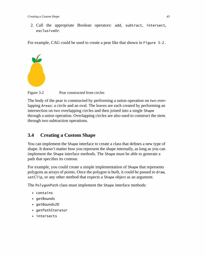
Creating a Custom Shape 43
ver-an
stem
ofu can
2. Call the appropriate Boolean operators:add, subtract, intersect,exclusiveOr.
For example, CAG could be used to create a pear like that shown inFigure 3-2.
Figure 3-2 Pear constructed from circles
The body of the pear is constructed by performing a union operation on two olappingAreas: a circle and an oval. The leaves are each created by performingintersection on two overlapping circles and then joined into a singleShape
through a union operation. Overlapping circles are also used to construct thethrough two subtraction operations.
3.4 Creating a Custom Shape
You can implement theShape interface to create a class that defines a new typeshape. It doesn’t matter how you represent the shape internally, as long as yoimplement theShape interface methods. TheShape must be able to generate apath that specifies its contour.
For example, you could create a simple implementation ofShape that representspolygons as arrays of points. Once the polygon is built, it could be passed todraw,setClip, or any other method that expects aShape object as an argument.
ThePolygonPath class must implement theShape interface methods:
• contains
• getBounds
• getBounds2D
• getPathIterator
• intersects

Geometries, JavaTM 2 SDK, Standard Edition, 1.3 Version44

4
ttextrted
ain
ost
Fonts and Text Layou
You can use the Java 2D™ API transformation and drawing mechanisms withstrings. In addition, the Java 2D API provides text-related classes that suppofine-grain font control and sophisticated text layout. These include an enhancFont class and the newTextLayout class.
This chapter focuses on the new font and text layout capabilities supportedthrough interfaces and classes in java.awt, andjava.awt.font. For moreinformation about using these features, see the 2D Text Tutorial that’s avail-able through the Java Developer Connection at http://devel-oper.java.sun.com/developer/onlineTraining/Graphics/2DText/.
For information about text analysis and internationalization, refer to thejava.text documentation and the “Writing Global Programs” track in the JavTutorial. For information about using the text layout mechanisms implementedSwing, see thejava.awt.swing.text documentation and “Using the JFC/SwingPackages” in the Java Tutorial.
Note: The information on international text layout contained in this chapter isbased on the paperInternational Text in JDK 1.2 by Mark Davis, Doug Felt, andJohn Raley, copyright 1997, Taligent, Inc.
4.1 Interfaces and Classes
The following tables list the key font and text layout interfaces and classes. Mof these interfaces and classes are part of thejava.awt.font package. Some, likeFont, are part of thejava.awt package to maintain backward compatibility withearlier versions of the JDK.
45

Fonts and Text Layout, JavaTM 2 SDK, Standard Edition, 1.3 Version46
il-a-
h
-
e-
lineng,
Interface Description
MultipleMaster Represents Type 1 Multiple Master fonts. Implemented byFont objects that aremultiple master fonts to enable access to multiple master design controls.
OpenType Represents Open Type and True Type fonts. Implemented byFont objects thatare Open Type or True Type fonts to enable access to the font’ssfnt tables.
Class Description
Font(java.awt)
Represents an instance of a font face from the collection of font faces avaable on the host system. Supports the specification of detailed font informtion and provides access to information about the font and its glyphs.
FontRenderContext Encapsulates the information necessary to correctly measure text.
GlyphJustificationInfo Represents information about the justification properties of a glyph, sucas weight, priority, absorb, and limit.
GlyphMetrics Provides metrics for a single glyph.
GlyphVector A collection of glyphs and their positions.
GraphicAttribute Base class for aTextLayout attribute that specifies a graphic to be embedded within text. Implemented byShapeGraphicAttribute andImage-GraphicAttribute, which enableShapes andImages to be embedded inaTextLayout. Can be subclassed to implement custom character replacment graphics.
ImageGraphicAttribute Extends:GraphicAttributeA GraphicsAttribute used to drawImages within aTextLayout.
LineBreakMeasurer Breaks a block of text that spans multiple lines intoTextLayout objects that fit within a specified line length.
LineMetrics Provides access to the font metrics needed to lay out characters along aand to lay out a set of lines. These metrics include ascent, descent, leadiheight, and baseline information.
ShapeGraphicAttribute Extends:GraphicAttributeA GraphicsAttribute used to drawShapes within aTextLayout.
TextAttribute Defines attribute keys and values used for text rendering.
TextHitInfo Represents hit test information for characters in aTextLayout.

Font Concepts 47
font
t
tscify
rm,
rieve
.It’s
with
, in-
4.2 Font Concepts
The Font class has been enhanced to support the specification of detailedinformation and enable the use of sophisticated typographic features.
A Font object represents an instance of a font face from the collection of fonfaces available on the system. Examples of common font faces includeHelvet-
ica Bold andCourier Bold Italic.
Three names are associated with aFont—its logical name, family name, and fontface name:
• A Font object’slogical nameis a name mapped onto one of the specific fonavailable on the platform. The logical font name is the name used to speaFont in JDK 1.1 and earlier releases. When specifying aFont in Java™ 2SDK, you should use thefont face nameinstead of the logical name.You canget the logical name from theFont by callinggetName. To get a list of thelogical names that are mapped onto the specific fonts available on a platfocall java.awt.Toolkit.getFontList.
• A Font object’sfamily name is the name of the font family that determinesthe typographic design across several faces, such as Helvetica. You retthe family name through thegetFamily method.
• A Font objects’font face namerefers to an actual font installed on the systemThis is the name you should use when specifying a font in Java 2 SDK. often referred to as just thefont name. You can retrieve the font name bycallinggetFontName. To determine which font faces are available on thesystem, you can callGraphicsEnvironment.getAllFonts.
You can access information about aFont through thegetAttributes method. AFont’s attributes include its name, size, transform, and font features such asweight and posture.
A LineMetrics object encapsulates the measurement information associatedaFont, such as its ascent, descent, and leading:
TextLayout Implements:CloneableProvides an immutable graphical representation of styled character datacluding bidirectional text.
Class Description

Fonts and Text Layout, JavaTM 2 SDK, Standard Edition, 1.3 Version48
cet
st
line
osi-the-
ris-
ned
ra-
• Ascent is the distance from the baseline to the ascender line. This distanrepresents the typical height of capital letters, but some characters mighextend above the ascender line.
• Descent is the distance from the baseline to the descender line. The lowepoint of most characters will fall within the descent, but some charactersmight extend below the descender line.
• Leadingis the recommended distance from the bottom of the descenderto the top of the next line.
Figure 4-1 Line Metrics
This information is used to properly position characters along a line, and to ption lines relative to one another. You can access these line metrics through getAscent, getDescent, andgetLeading methods. You can also access information about aFont’s height, baseline, and underline and strikethrough charactetics throughLineMetrics.
4.3 Text Layout Concepts
Before a piece of text can be displayed, it must be properly shaped and positiousing the appropriate glyphs and ligatures. This process is referred to astext lay-out. The text layout process involves:
• Shaping text using the appropriate glyphs and ligatures.
• Properly ordering the text.
• Measuring and positioning the text.
The information used to lay out text is also necessary for performing text opetions such as caret positioning, hit detection, and highlighting.
dfac ascender line
descender line
next line
baseline
egbd

Text Layout Concepts 49
beopri-
size,n beng on
iffer-
aysbic;
For
sive.
ge to
To develop software that can be deployed in international markets, text mustlaid out in different languages in a way that conforms to the rules of the apprate writing system.
4.3.1 Shaping Text
A glyph is the visual representation of one or more characters. The shape,and position of a glyph is dependent on its context. Many different glyphs caused to represent a single character or combination of characters, dependithe font and style.
For example, in handwritten cursive text, a particular character can take on dent shapes depending on how it is connected to adjacent characters.
In some writing systems, particularly Arabic, the context of a glyph must alwbe taken into account. Unlike in English, cursive forms are mandatory in Arait is unacceptable to present text without using cursive forms.
Depending on the context, these cursive forms can differ radically in shape. example, the Arabic letterheh has the four cursive forms shown in Figure 4-2.
Figure 4-2 Cursive Forms in Arabic
Although these four forms are quite different from one another, such curshape-changing is not fundamentally different from cursive writing in English
In some contexts, two glyphs can change shape even more radically and merform a single glyph. This type of merged glyph is called aligature. For example,most English fonts contain the ligature fi shown in Figure 4-3. The merged glyphtakes into account the overhang on the letter f and combines the characters in anatural-looking way, instead of simply letting the letters collide.
UnconnectedConnecton Right
Connect onBoth Sides
Connecton Left

Fonts and Text Layout, JavaTM 2 SDK, Standard Edition, 1.3 Version50
y—itthe
theple,gle
acterry inad
e
hst to
Figure 4-3 EnglishLigatures
Ligatures are also used in Arabic and the use of some ligatures is mandatoris unacceptable to present certain character combinations without usingappropriate ligature. When ligatures are formed from Arabic characters,shapes change even more radically than they do in English. For examFigure 4-4 illustrates how two Arabic characters are combined into a sinligature when they appear together.
Figure 4-4 ArabicLigatures
4.3.2 Ordering Text
In the Java™ programming language, text is encoded using Unicode charencoding. Text that uses Unicode character encoding is stored in memological order. Logical order is the order in which characters and words are reand written. The logical order is not necessarily the same as thevisual order, theorder in which the corresponding glyphs are displayed.
The visual order for glyphs in a particular writing system (script) is called thescript order. For example, the script order for Roman text is left-to-right and thscript order for Arabic and Hebrew is right-to-left.
Some writing systems have rules in addition to script order for arranging glypand words on lines of text. For example, Arabic and Hebrew numbers run lef
a b
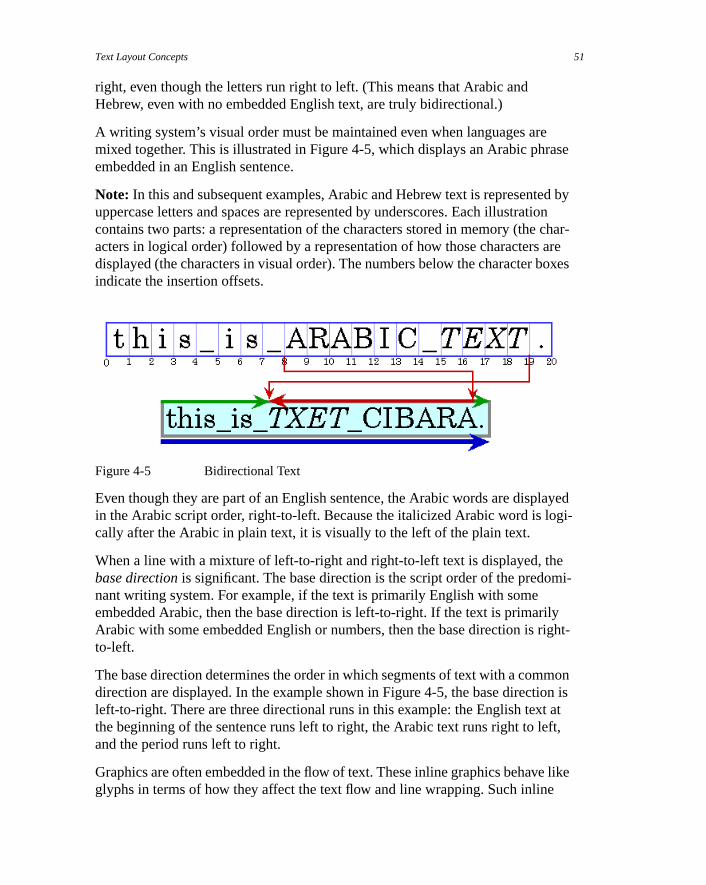
Text Layout Concepts 51
ease
d bytion char- areoxes
ayedgi-
emi-
lyright-
monon is atft,
like
right, even though the letters run right to left. (This means that Arabic andHebrew, even with no embedded English text, are truly bidirectional.)
A writing system’s visual order must be maintained even when languages armixed together. This is illustrated in Figure 4-5, which displays an Arabic phrembedded in an English sentence.
Note: In this and subsequent examples, Arabic and Hebrew text is representeuppercase letters and spaces are represented by underscores. Each illustracontains two parts: a representation of the characters stored in memory (theacters in logical order) followed by a representation of how those charactersdisplayed (the characters in visual order). The numbers below the character bindicate the insertion offsets.
Figure 4-5 Bidirectional Text
Even though they are part of an English sentence, the Arabic words are displin the Arabic script order, right-to-left. Because the italicized Arabic word is locally after the Arabic in plain text, it is visually to the left of the plain text.
When a line with a mixture of left-to-right and right-to-left text is displayed, thbase direction is significant. The base direction is the script order of the predonant writing system. For example, if the text is primarily English with someembedded Arabic, then the base direction is left-to-right. If the text is primariArabic with some embedded English or numbers, then the base direction is to-left.
The base direction determines the order in which segments of text with a comdirection are displayed. In the example shown in Figure 4-5, the base directileft-to-right. There are three directional runs in this example: the English textthe beginning of the sentence runs left to right, the Arabic text runs right to leand the period runs left to right.
Graphics are often embedded in the flow of text. These inline graphics behaveglyphs in terms of how they affect the text flow and line wrapping. Such inline

Fonts and Text Layout, JavaTM 2 SDK, Standard Edition, 1.3 Version52
so
ard,
aveakeple,
ungly.
Inpend-d to-
ualoringepend-
text
the
graphics need to be positioned using the same bidirectional layout algorithmthat they appear in the proper location in the flow of characters.
For more information about the precise algorithm used to order glyphs withinline, see the description of the Bidirectional Algorithm in The Unicode StandaVersion 2.0, Section 3.11.
4.3.3 Measuring and Positioning Text
Unless you are working with a monospace font, different characters in a font hdifferent widths. This means that all positioning and measuring of text has to tinto account exactly which characters are used, not just how many. For examto right-align a column of numbers displayed in a proportional font, you can’tsimply use extra spaces to position the text. To properly align the column, yoneed to know the exact width of each number so that you can adjust accordi
Text is often displayed using multiple fonts and styles, such as bold or italic. this case, even the same character can have different shapes and widths, deing on how it is styled. To properly position, measure, and render text, you neekeep track of each individual characterandthe style applied to that character. Fortunately,TextLayout does this for you.
To properly display text in languages such as Hebrew and Arabic, each individcharacter needs to be measured and positioned within the context of neighbcharacters. Because the shapes and positions of the characters can change ding on the context, measuring and positioning such text without taking the coninto account produces unacceptable results.
4.3.4 Supporting Text Manipulation
To allow the user to edit the text that is displayed, you must be able to:
• Display a caret that indicates where new characters will be inserted whenuser enters text.
• Move the caret and insertion point in response to user input.
• Detect user selections (hit detection).
• Highlight selected text.

Text Layout Concepts 53
nt,t isrted
ltionsyedretsonds.
thef
)ertedbasebe
of, the
4.3.4.1 Displaying Carets
In editable text, acaret is used to graphically represent the current insertion poithe position in the text where new characters will be inserted. Typically, a careshown as a blinking vertical bar between two glyphs. New characters are inseand displayed at the caret's location.
Calculating the caret position can be complicated, particularly for bidirectionatext. Insertion offsets on directional boundaries have two possible caret posibecause the two glyphs that correspond to the character offset are not displaadjacent to one another. This is illustrated in Figure 4-6. In this figure, the caare shown as square brackets to indicate the glyph to which the caret corresp
Figure 4-6 Dual Carets
Character offset 8 corresponds to the location after the _ and before theA. If theuser enters an Arabic character, its glyph is displayed to the right of (before)A; if the user enters an English character, its glyph is displayed to the right o(after) the _.
To handle this situation, some systems display dual carets, a strong (primarycaret and a weak (secondary) caret. The strong caret indicates where an inscharacter will be displayed when that character's direction is the same as thedirection of the text. The weak caret shows where an inserted character will displayed when the character's direction is the opposite of the base direction.Tex-
tLayout automatically supports dual carets;JTextComponent does not.
When you’re working with bidirectional text, you can’t simply add the widths the glyphs before a character offset to calculate the caret position. If you didcaret would be drawn in the wrong place, as shown in Figure 4-7.
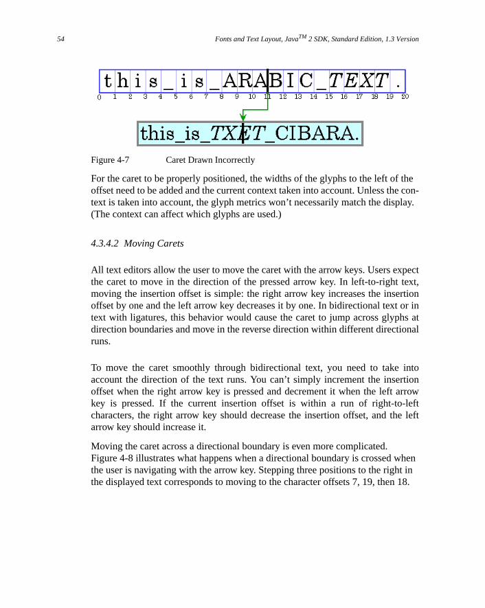
Fonts and Text Layout, JavaTM 2 SDK, Standard Edition, 1.3 Version54
thecon-
lay.
ectxt,
tionr ins atnal
intoionrrowft
e left
hent in 18.
Figure 4-7 Caret Drawn Incorrectly
For the caret to be properly positioned, the widths of the glyphs to the left of offset need to be added and the current context taken into account. Unless thetext is taken into account, the glyph metrics won’t necessarily match the disp(The context can affect which glyphs are used.)
4.3.4.2 Moving Carets
All text editors allow the user to move the caret with the arrow keys. Users expthe caret to move in the direction of the pressed arrow key. In left-to-right temoving the insertion offset is simple: the right arrow key increases the inseroffset by one and the left arrow key decreases it by one. In bidirectional text otext with ligatures, this behavior would cause the caret to jump across glyphdirection boundaries and move in the reverse direction within different directioruns.
To move the caret smoothly through bidirectional text, you need to takeaccount the direction of the text runs. You can’t simply increment the insertoffset when the right arrow key is pressed and decrement it when the left akey is pressed. If the current insertion offset is within a run of right-to-lecharacters, the right arrow key should decrease the insertion offset, and tharrow key should increase it.
Moving the caret across a directional boundary is even more complicated.Figure 4-8 illustrates what happens when a directional boundary is crossed wthe user is navigating with the arrow key. Stepping three positions to the righthe displayed text corresponds to moving to the character offsets 7, 19, then

Text Layout Concepts 55
houldreomore
ple, con-is is
-
tingat
Figure 4-8 Caret Movement
Certain glyphs should never have a caret between them; instead, the caret smove as though the glyphs represented a single character. For example, theshould never be a caret between ano and an umlaut if they are represented by twseparate characters. (See The Unicode Standard, Version 2.0, Chapter 5, forinformation.)
TextLayout provides methods (getNextRightHit andgetNextLeftHit) thatenable you to easily move the caret smoothly through bidirectional text.
4.3.4.3 Hit Testing
Often, a location in device space must be converted to a text offset. For examwhen a user clicks the mouse on selectable text, the location of the mouse isverted to a text offset and used as one end of the selection range. Logically, ththe inverse of positioning a caret.
When you’re working with bidirectional text, a single visual location in the display can correspond to two different offsets in the source text, as shown inFigure 4-9.
Figure 4-9 Hit Testing Bidirectional Text
Because a single visual location can correspond to two different offsets, hit tesbidirectional text isn’t just a matter of measuring glyph widths until the glyph

Fonts and Text Layout, JavaTM 2 SDK, Standard Edition, 1.3 Version56
tero
n, anent
forghthto a
ebe
us.
the correct location is found and then mapping that position back to a characoffset. Detecting the side that the hit was on helps distinguish between the twalternatives.
You can perform hit testing usingTextLayout.hitTestChar. Hit information isencapsulated in aTextHitInfo object and includes information about the sidethat the hit was on.
4.3.4.4 Highlighting Selections
A selected range of characters is represented graphically by a highlight regioarea in which glyphs are displayed with inverse video or against a differbackground color.
Highlight regions, like carets, are more complicated for bidirectional text thanmonodirectional text. In bidirectional text, a contiguous range of characters minot have a contiguous highlight region when displayed. Conversely, a highligregion showing a visually contiguous range of glyphs might not correspond tsingle, contiguous range of characters.
This results in two strategies for highlighting selections in bidirectional text:
• Logical highlighting —with logical highlighting, the selected characters aralways contiguous in the text model, and the highlight region is allowed todiscontiguous. For an example of logical highlighting, see Figure 4-10.
• Visual highlighting—with visual highlighting, there might be more than onerange of selected characters, but the highlight region is always contiguoFor an example of visual highlighting, see Figure 4-11.
Figure 4-10 Logical Highlighting (contiguous characters)

Text Layout Concepts 57
e
con-
ou
ial.
tre
t
Figure 4-11 Visual Highlighting (contiguous highlight region)
Logical highlighting is simpler to implement, since the selected characters aralways contiguous in the text.
4.3.5 Performing Text Layout in a Java™ Application
Depending on which Java™ APIs you use, you can have as little or as muchtrol over text layout as you need:
• If you just want to display a block of text or need an editable text control, ycan useJTextComponent, which will perform the text layout for you.JTextComponent is designed to handle the needs of most internationalapplications and supports bidirectional text For more information aboutJTextComponent, see “Using the JFC/Swing Packages” in the Java Tutor
• If you want to display a simple text string, you can callGraphics2D.drawString and let Java 2D™ lay out the string for you. Youcan also usedrawString to render styled strings and strings that containbidirectional text. For more information about rendering text throughGraphics2D, see “Rendering Graphics Primitives” on page 36.
• If you want to implement your own text editing routines, you can useTextLayout to manage text layout, highlighting, and hit detection. Thefacilities provided byTextLayout handle most common cases, including texstrings with mixed fonts, mixed languages, and bidirectional text. For moinformation about using TextLayout, see “Managing Text Layout” onpage 58.
• If you want total control over how text is shaped and positioned, you canconstruct your ownGlyphVectors usingFont and then render them throughGraphics2D. For more information about implementing your own text layoumechanism, see “Implementing a Custom Text Layout Mechanism” onpage 63.
Fonts and Text Layout, JavaTM 2 SDK, Standard Edition, 1.3 Version58
ostdlionnes,
ers
rder
u
.
atsingcanys-
Generally, you do not need to perform text layout operations yourself. For mapplications,JTextComponent is the best solution for displaying static aneditable text. However,JTextComponent does not support the display of duacarets or discontiguous selections in bidirectional text. If your applicatrequires these features, or you prefer to implement your own text editing routiyou can use the Java 2D text layout APIs.
4.4 Managing Text Layout
The TextLayout class supports text that contains multiple styles and charactfrom different writing systems, including Arabic and Hebrew. (Arabic andHebrew are particularly difficult to display because you must reshape and reothe text to achieve an acceptable representation.)
TextLayout simplifies the process of displaying and measuring text even if yoare working with English-only text. By usingTextLayout, you can achieve high-quality typography with no extra effort.
TheTextLayout class manages the positioning and ordering of glyphs for youYou can useTextLayout to:
• Lay out monodirectional and bidirectional text
• Display and move carets
• Perform hit testing on text
• Highlight text selections
In some situations, you might want to compute the text layout yourself, so thyou can control exactly which glyphs are used and where they are placed. Uinformation such as glyph sizes, kerning tables, and ligature information, youconstruct your own algorithms for computing the text layout, bypassing the stem’s layout mechanism. For more information, see “Implementing a CustomText Layout Mechanism” on page 63.
Text Layout Performance
TextLayout is designed so that there is no significant performance impact
when it’s used to display simple, monodirectional text. There is some addition-
al processing overhead when TextLayout is used to display Arabic or Hebrew
text. However, it’s typically on the order of microseconds per character and is
dominated by the execution of normal drawing code.

Managing Text Layout 59
yphs
a
n a
t. If
c-,
.
lyphsnce.
the
f
4.4.1 Laying Out Text
TextLayout automatically lays out text, including bidirectional (BIDI) text, withthe correct shaping and ordering. To correctly shape and order the glrepresenting a line of text,TextLayout must know the full context of the text:
• If the text fits on a single line, such as a single-word label for a button orline in a dialog box, you can construct aTextLayout directly from the text.
• If you have more text than can fit on a single line or want to break text osingle line into tabbed segments, you cannot construct aTextLayout directly.You must use aLineBreakMeasurer to provide sufficient context.
The base direction of the text is normally set by an attribute (style) on the texthat attribute is missing,TextLayout follows the Unicode bidirectional algorithmand derives the base direction from the initial characters in the paragraph.
4.4.2 Displaying Dual Carets
TextLayout maintains caret information such as the caretShape, position, andangle. You can use this information to easily display carets in both monodiretional and bidirectional text. When you’re drawing carets for bidirectional textusingTextLayout ensures that the carets will be positioned correctly.
TextLayout provides default caretShapes and automatically supports dual caretsFor italic and oblique glyphs,TextLayout produces angled carets, as shown inFigure 4-12. These caret positions are also used as the boundaries between gfor highlighting and hit testing, which helps produce a consistent user experie
Figure 4-12 Angled Carets
Given an insertion offset, thegetCaretShapes method returns a two-elementarray ofShapes: element 0 contains the strong caret and element 1 contains weak caret, if one exists. To display dual carets, you simply draw both caretShapes; the carets will be automatically be rendered in the correct positions.
If you want to use custom caretShapes, you can retrieve the position and angle othe carets from theTextLayout and draw them yourself.

Fonts and Text Layout, JavaTM 2 SDK, Standard Edition, 1.3 Version60
a
owr
a
s a
ffset
In the following example, the default strong and weak caretShapes are drawn indifferent colors. This is a common way to differentiate dual carets.
Shape[] caretShapes = layout.getCaretShapes(hit);g2.setColor(PRIMARY_CARET_COLOR);g2.draw(caretShapes[0]);if (caretShapes[1] != null){ g2.setColor(SECONDARY_CARET_COLOR); g2.draw(caretShapes[1]);}
4.4.3 Moving the Caret
You can also useTextLayout to determine the resulting insertion offset whenuser presses the left or right arrow key. Given aTextHitInfo object thatrepresents the current insertion offset, thegetNextRightHit method returns aTextHitInfo object that represents the correct insertion offset if the right arrkey is pressed. ThegetNextLeftHit method provides the same information fothe left arrow key.
In the following example, the current insertion offset is moved in response toright arrow key.
TextHitInfo newInsertionOffset = layout.getNextRightHit(insertionOffset);if (newInsertionOffset != null) { Shape[] caretShapes = layout.getCaretShapes(newInsertionOffset); // draw carets ... insertionOffset = newInsertionOffset;}
4.4.4 Hit Testing
TextLayout provides a simple mechanism for hit testing text. ThehitTestChar
method takesx and y coordinates from the mouse as arguments and returnTextHitInfo object. TheTextHitInfo contains the insertion offset for thespecified position and the side that the hit was on. The insertion offset is the o

Managing Text Layout 61
the
t itt,
ng
closest to the hit: if the hit is past the end of the line, the offset at the end ofline is returned.
In the following example,hitTestChar is called on aTextLayout and thenget-InsertIndex is used to retrieve the offset.
TextHitInfo hit = layout.hitTestChar(x, y);int insertIndex = hit.getInsertIndex();
4.4.5 Highlighting Selections
You can get aShape that represents the highlight region from theTextLayout.TextLayout automatically takes the context into account when calculating thedimensions of the highlight region.TextLayout supports both logical and visualhighlighting.
In the following example, the highlight region is filled with the highlight colorand then theTextLayout is drawn over the filled region. This is one simple wayto display highlighted text.
Shape highlightRegion = layout.getLogicalHighlightShape(hit1, hit2);graphics.setColor(HIGHLIGHT_COLOR);graphics.fill(highlightRegion);graphics.drawString(layout, 0, 0);
4.4.6 Querying Layout Metrics
TextLayout provides access to graphical metrics for the entire range of texrepresents. Metrics available fromTextLayout include the ascent, descenleading, advance, visible advance, and the bounding rectangle.
More than oneFont can be associated with aTextLayout: different style runs canuse different fonts. The ascent and descent values for aTextLayout are themaximum values of all of the fonts used in theTextLayout. The computation oftheTextLayout's leading is more complicated; it’s not just the maximum leadivalue.
Fonts and Text Layout, JavaTM 2 SDK, Standard Edition, 1.3 Version62
emes
tightthe
es.in
tle.o-
the
his
gthese
The advance of aTextLayout is its length: the distance from the left edge of thleftmost glyph to the right edge of the rightmost glyph. The advance is sometireferred to as thetotal advance. The visible advanceis the length of theTextLayout without its trailing whitespace.
The bounding box of aTextLayout encloses all of the text in the layout. Iincludes all the visible glyphs and the caret boundaries. (Some of these mhang over the origin or origin + advance). The bounding box is relative toorigin of theTextLayout, not to any particular screen position.
In the following example, the text in aTextLayout is drawn within the layout’sbounding box.
graphics.drawString(layout, 0, 0);Rectangle2D bounds = layout.getBounds();graphics.drawRect(bounds.getX()-1, bounds.getY()-1, bounds.getWidth()+2, bounds.getHeight()+2);
4.4.7 Drawing Text Across Multiple Lines
TextLayout can also be used to display a piece of text that spans multiple linFor example, you might take a paragraph of text, line-wrap the text to a certawidth, and display the paragraph as multiple lines of text.
To do this, you do not directly create theTextLayouts that represent each line oftext—LineBreakMeasurer generates them for you. Bidirectional ordering cannoalways be performed correctly unless all of the text in a paragraph is availabLineBreakMeasurer encapsulates enough information about the context to prduce correctTextLayouts.
When text is displayed across multiple lines, the length of the lines is usuallydetermined by the width of the display area. Line breaking (line wrapping) is process of determining where lines begin and end, given a graphical width inwhich the lines must fit.
The most common strategy is to place as many words on each line as will fit. Tstrategy is implemented inLineBreakMeasurer. Other more complex line breakstrategies use hyphenation, or attempt to minimize the differences in line lenwithin paragraphs. The Java 2D™ API does not provide implementations of thstrategies.
Implementing a Custom Text Layout Mechanism 63
r-
es
n
s in
es the
-yed.ents
To break a paragraph of text into lines, you construct aLineBreakMeasurer withthe entire paragraph and then callnextLayout to step through the text and geneateTextLayouts for each line.
To do this, LineBreakMeasurer maintains an offset within the text. Initially, theoffset is at the beginning of the text. Each call tonextLayout moves the offset bythe character count of theTextLayout that was created. When this offset reachthe end of the text,nextLayout returnsnull.
The visible advance of eachTextLayout that the LineBreakMeasurer createsdoesn’t exceed the specified line width. By varying the width you specify wheyou callnextLayout, you can break text to fit complicated areas, such as anHTML page with images in fixed positions or tab-stop fields. You can also pasaBreakIterator to tell LineBreakMeasurer where valid breakpoints are; if youdon't supply one theBreakIterator for the default locale is used.
In the following example, a bilingual text segment is drawn line by line. The linare aligned to either to the left margin or right margin, depending on whetherbase text direction is left-to-right or right-to-left.
Point2D pen = initialPosition;LineBreakMeasurer measurer = new LineBreakMeasurer(styledText,myBreakIterator);while (true) { TextLayout layout = measurer.nextLayout(wrappingWidth); if (layout == null) break; pen.y += layout.getAscent(); float dx = 0; if (layout.isLeftToRight()) dx = wrappingWidth - layout.getAdvance(); layout.draw(graphics, pen.x + dx, pen.y); pen.y += layout.getDescent() + layout.getLeading();}
4.5 Implementing a Custom Text Layout Mechanism
TheGlyphVector class provides a way to display the results of custom layoutmechanisms. AGlyphVector object can be thought of as the output of an algorithm that takes a string and computes exactly how the string should be displaThe system has a built-in algorithm and the Java 2D™ API lets advanced clidefine their own algorithms.

Fonts and Text Layout, JavaTM 2 SDK, Standard Edition, 1.3 Version64
stics
-
cus-lay
A GlyphVector object is basically an array of glyphs and glyph locations. Glyphare used instead of characters to provide total control over layout characterissuch as kerning and ligatures. For example, when displaying the string “final”,you might want to replace the leadingfi substring with the ligaturefi. In thiscase, theGlyphVector object will have fewer glyphs than the number of characters in the original string.
Figure 4-13 and Figure 4-14 illustrate howGlyphVector objects are used by lay-out mechanisms. Figure 4-13 shows the default layout mechanism. Whendraw-
String is called on aString, the built-in layout algorithm:
• Uses the currentFont in theGraphics2D context to determine which glyphsto use.
• Calculates where each glyph should be placed.
• Stores the resulting glyph and position information in aGlyphVector.
• Passes theGlyphVector to a glyph rendering routine that does the actualdrawing.
Figure 4-13 Using the Built-in Layout Algorithm
Figure 4-14 shows the process for using a custom layout algorithm. To use atom layout algorithm, you must assemble all of the information necessary to out the text. The basic process is the same:
• Using theFont, determine which glyphs to use
• Determine where to place the glyphs
• Store this layout information in aGlyphVector
final
GlyphVector
font
glyph-ids
x-posns
y-posns
drawString
GlyphRenderer
Built-inLayoutAlgorithm
SimpleString

Creating Font Derivations 65
f
ring.
To render the text, you pass theGlyphVector to drawString, which in turnpasses it to the glyph renderer. In Figure 4-14, the custom layout algorithmreplaces thefi substring with the ligaturefi.
Figure 4-14 Using a Custom Layout Algorithm
4.6 Creating Font Derivations
Using theFont.deriveFont methods, you can create a newFont object withdifferent attributes from an existingFont object. Often, a transform is applied tothe existingFont to create a new derivedFont. To do this, you:
1. Create aFont object.,
2. Create theAffineTransform you want to apply to theFont.
3. CallFont.deriveFont, passing in theAffineTransform.
In this way, you could easily create aFont in a custom size or a skewed version oan existingFont.
In the following code excerpt, anAffineTransform is applied to create a skewedversion of the font Helvetica. The new derived font is then used to render a st
// Create a transformation for the font.AffineTransform fontAT = new AffineTransform();fontAT.setToShear(-1.2, 0.0);// Create a Font Object.Font theFont = new Font("Helvetica", Font.PLAIN, 1);// Derive a new font using the shear transformtheDerivedFont = theFont.deriveFont(fontAT);// Add the derived font to the Graphics2D contextg2.setFont(theDerivedFont);
final
drawString
GlyphRenderer
ClientLayoutAlgorithm
GlyphVectorcollection
Fontparameters

Fonts and Text Layout, JavaTM 2 SDK, Standard Edition, 1.3 Version66
// Render a string using the derived fontg2.drawString(“Java”, 0.0f, 0.0f);
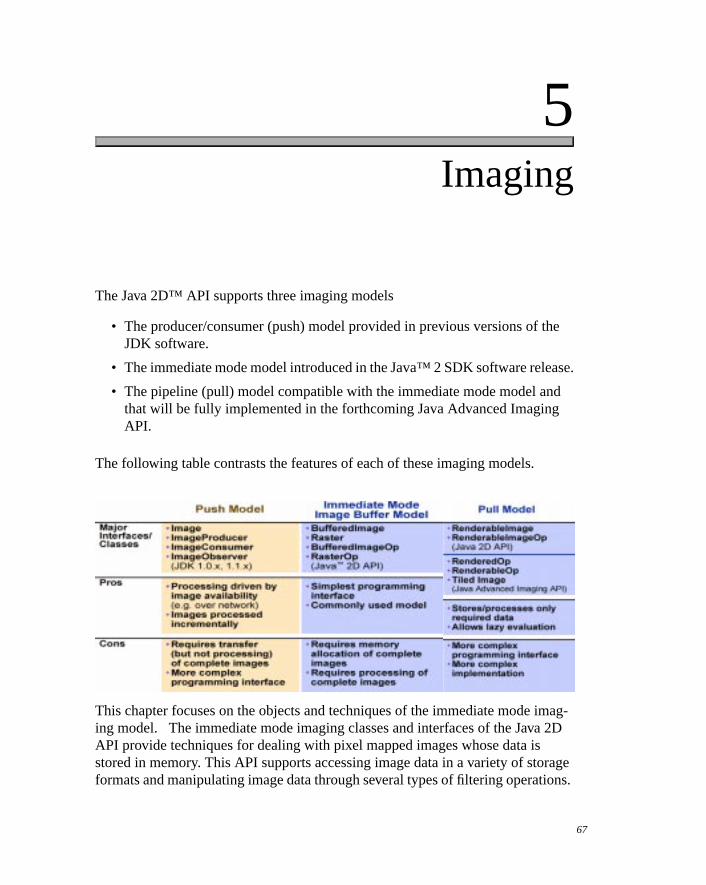
5
he
ase.
d
mag- 2D
rageons.
Imaging
The Java 2D™ API supports three imaging models
• The producer/consumer (push) model provided in previous versions of tJDK software.
• The immediate mode model introduced in the Java™ 2 SDK software rele
• The pipeline (pull) model compatible with the immediate mode model anthat will be fully implemented in the forthcoming Java Advanced ImagingAPI.
The following table contrasts the features of each of these imaging models.
This chapter focuses on the objects and techniques of the immediate mode iing model. The immediate mode imaging classes and interfaces of the JavaAPI provide techniques for dealing with pixel mapped images whose data isstored in memory. This API supports accessing image data in a variety of stoformats and manipulating image data through several types of filtering operati
67

Imaging, JavaTM 2 SDK, Standard Edition, 1.3 Version68
sixmodel
e
e
a-
led
5.1 Interfaces and Classes
The immediate mode imaging APIs in the Java 2D™ API can be grouped intocategories: interfaces, image data classes, image operation classes, sampleclasses, color model classes, and exceptions.
5.1.1 Imaging Interfaces
5.1.2 Image Data Classes
Interface Description
BufferedImageOp Describes single-input/single-output operations performed onBuffered-
Image objects. Implemented byAffineTransformOp, ColorConvertOp,ConvolveOp, LookupOp, andRescaleOp.
RasterOp Defines single-input/single-output operations performed onRaster ob-jects. Implemented byAffineTransformOp, BandCombineOp, ColorCon-vertOp, ConvolveOp, LookupOp, andRescaleOp.
RenderedImage Defines a common protocol for objects that contain or can produce imagdata in the form ofRasters.
WritableRenderedImage Extends:RenderedImageDefines a common protocol for objects that contain or can produce imagdata in the form ofRasters which can be modified.
TileObserver Defines a protocol for objects that want to be notified when the modifiction state of aWritableRenderedImage changes.
Class Description
BufferedImage Extends:ImageImplements:WriteableRenderedImageAn image with an accessible data buffer. ABufferedImage has aColor-Model and aRaster of image data.
ByteLookupTable Extends:LookupTableA LookupTable that contains byte data.
DataBuffer Wraps one or more data arrays holding pixel data. Each data array is calabank.

Interfaces and Classes 69
g
PI)
t
.
p-
r-
-
-
5.1.3 Image Operation Classes
DataBufferByte Extends:DataBuffer (Final)A data buffer that stores bytes of data. (Used in Java Advanced ImaginAPI)
DataBufferInt Extends:DataBuffer (Final))A data buffer that stores integer data.(Used in Java Advanced ImagingAPI)
DataBufferShort Extends:DataBuffer (Final)A data buffer that stores short data.(Used in Java Advanced Imaging A
DataBufferUShort Extends:DataBuffer (Final)A data buffer that stores unsigned short data.
Kernel A matrix that describes how an input pixel and its surrounding pixels affecthe value of an output pixel in aConvolveOp filtering operation.
LookupTable Extends:ObjectA table that maps values from single-banded pixel data to color values
Raster A rectangular array of pixels from which you can retrieve image data. ARaster contains aDataBuffer and aSampleModel.
ShortLookupTable Extends:LookupTableA lookup table that contains short data.
WritableRaster Extends:RasterA Raster that you can modify.
Class Description
AffineTransformOp Implements:BufferedImageOp, RasterOpA class that defines an affine transform to perform a linear maping from 2D coordinates in a sourceImage or Raster to 2D co-ordinates in the destination image orRaster. This class canperform either bilinear or nearest neighbor affine transform opeations.
BandCombineOp Implements:RasterOpUsing a specified matrix, this operation performs an arbitrary linear combination of bands in aRaster.
BufferedImageFilter Extends:ImageFilterAn ImageFilter that provides a simple means of using aBuff-eredImageOp (a single-source/single-destination image operator) to filter aBufferedImage or Raster.
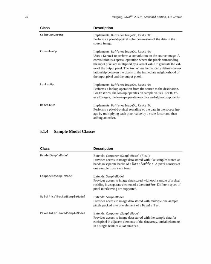
Imaging, JavaTM 2 SDK, Standard Edition, 1.3 Version70
l-
f
.
.
-
as
el
ts
5.1.4 Sample Model Classes
ColorConvertOp Implements:BufferedImageOp, RasterOpPerforms a pixel-by-pixel color conversion of the data in thesource image.
ConvolveOp Implements:BufferedImageOp, RasterOpUses aKernel to perform a convolution on the source image. Aconvolution is a spatial operation where the pixels surroundingthe input pixel are multiplied by a kernel value to generate the vaue of the output pixel. TheKernel mathematically defines the re-lationship between the pixels in the immediate neighborhood othe input pixel and the output pixel.
LookupOp Implements:BufferedImageOp, RasterOpPerforms a lookup operation from the source to the destinationForRasters, the lookup operates on sample values. ForBuff-
eredImages, the lookup operates on color and alpha components
RescaleOp Implements:BufferedImageOp, RasterOpPerforms a pixel-by-pixel rescaling of the data in the source image by multiplying each pixel value by a scale factor and thenadding an offset.
Class Description
BandedSampleModel Extends:ComponentSampleModel (Final)Provides access to image data stored with like samples storedbands in separate banks of aDataBuffer. A pixel consists ofone sample from each band.
ComponentSampleModel Extends:SampleModelProvides access to image data stored with each sample of a pixresiding in a separate element of aDataBuffer. Different types ofpixel interleaving are supported.
MultiPixelPackedSampleModel Extends:SampleModelProvides access to image data stored with multiple one-samplepixels packed into one element of aDataBuffer.
PixelInterleavedSampleModel Extends:ComponentSampleModelProvides access to image data stored with the sample data foreach pixel in adjacent elements of the data array, and all elemenin a single bank of aDataBuffer.
Class Description
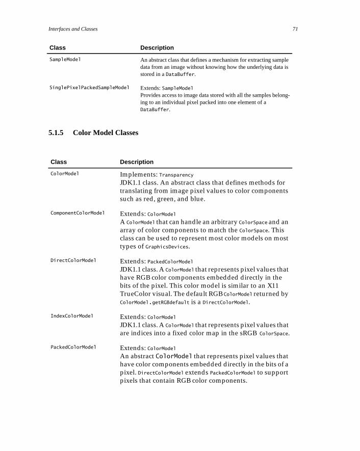
Interfaces and Classes 71
les
ng-
5.1.5 Color Model Classes
SampleModel An abstract class that defines a mechanism for extracting sampdata from an image without knowing how the underlying data istored in aDataBuffer.
SinglePixelPackedSampleModel Extends:SampleModelProvides access to image data stored with all the samples beloing to an individual pixel packed into one element of aDataBuffer.
Class Description
ColorModel Implements: Transparency
JDK1.1 class. An abstract class that defines methods for
translating from image pixel values to color components
such as red, green, and blue.
ComponentColorModel Extends: ColorModel
A ColorModel that can handle an arbitrary ColorSpace and an
array of color components to match the ColorSpace. This
class can be used to represent most color models on most
types of GraphicsDevices.
DirectColorModel Extends: PackedColorModel
JDK1.1 class. A ColorModel that represents pixel values that
have RGB color components embedded directly in the
bits of the pixel. This color model is similar to an X11
TrueColor visual. The default RGB ColorModel returned by
ColorModel.getRGBdefault is a DirectColorModel.
IndexColorModel Extends: ColorModel
JDK1.1 class. A ColorModel that represents pixel values that
are indices into a fixed color map in the sRGB ColorSpace.
PackedColorModel Extends: ColorModel
An abstract ColorModel that represents pixel values that
have color components embedded directly in the bits of a
pixel. DirectColorModel extends PackedColorModel to support
pixels that contain RGB color components.
Class Description

Imaging, JavaTM 2 SDK, Standard Edition, 1.3 Version72
inr of
ipu-
ti-
5.1.6 Exception Classes
5.2 Immediate Mode Imaging Concepts
The immediate mode imaging model supports fixed-resolution images storedmemory. The model also supports filtering operations on image data. A numbeclasses and interfaces are used in this model.
Figure 5-1 BufferedImage and supporting classes
As shown in Figure 5-1,BufferedImage provides general image management. ABufferedImage can be created directly in memory and used to hold and manlate image data retrieved from a file or URL. ABufferedImage can be displayedusing anyGraphics2D object for a screen device, or rendered to any other des
Class Description
ImagingOpException Extends: RuntimeExceptionThrown if one of the BufferedImageOp or RasterOp filter
methods can’t process the image.
RasterFormatException Extends: RuntimeExceptionThrown if there is invalid layout information in the Ras-
ter.

Immediate Mode Imaging Concepts 73
gularech-
pro-
al
s ond-
nation using appropriateGraphics2D context. ABufferedImage object containstwo other objects: aRaster and aColorModel.
TheRaster class provides image data management. It represents the rectancoordinates of the image, maintains image data in memory, and provides a manism for creating multiple subimages from a single image data buffer. It alsovides methods for accessing specific pixels within an image. A Raster objectcontains two other objects, aDataBuffer and aSampleModel.
TheDataBuffer class holds pixel data in memory.
TheSampleModel class interprets data in the buffer and provides it as individupixels or rectangular ranges of pixels.
TheColorModel class provides a color interpretation of pixel data provided bythe image’s sample model.
The image package provides additional classes that define filtering operationBufferedImage andRaster objects. Each image processing operation is emboied in a class that implements theBufferedImageOp interface, theRasterOpinterface, or both interfaces. The operation class definesfilter methods that per-forms the actual image manipulation.
Figure 5-2 illustrates the basic model for Java 2D™ API image processing:
Figure 5-2 Image Processing Model
The operations supported include:
• Affine transformation
• Amplitude scaling
• Lookup-table modification
• Linear combination of bands
• Color conversion
sourceimage
destinationimage
filter
image-processingoperation
Imaging, JavaTM 2 SDK, Standard Edition, 1.3 Version74
tly
ele-
lors:
tion
r alled inzesposi-ith at the
m-e.
ter-
• Convolution
Note that if you’re interested just in displaying and manipulating images, youonly need to understand theBufferedImage class and the filtering operationclasses. On the other hand, if you’re planning to write filters or otherwise direcaccess image data, you’ll need to understand the classes associated withBuff-
eredImage.
5.2.1 Terminology
Here are some terms used throughout the following discussions:
Data Elements: primitive types used as units of storage of image data. Data ments are individual members of aDataBuffer array. The layout of elements inthe data buffer is independent of the interpretation of the data as pixels by animage’sSampleModel.
Samples: distinct members of the pixels of an image. ASampleModel provides amechanism for converting elements in theDataBuffer to pixels and their sam-ples. The samples of a pixel may represent primary values in a particular comodel. For example, a pixel in an RGB color model consists of three samplered, green, and blue.
Components: values of pixels independent of color interpretation. The distincbetween component and sample is useful withIndexColorModel, where pixelcomponents are indexes into theLookupTable.
Band: the set of all samples of one type in an image, such as all red samples ogreen samples. Pixel data can be stored in a number of ways, the two supportthe Java 2D API being banded and pixel interleaved. Banded storage organiimage data by bands, and a pixel is made up of sample data from the same tion in each band. Pixel interleaved storage organizes image data by pixels, wsingle array containing all pixels, and bands consisting of the set of samples asame index position in each pixel.
Primaries: distinct members of a color value in a specific color model; for exaple the RGB model forms color values from the primaries red, green, and blu
5.3 Using BufferedImages
TheBufferedImage class is the main class supporting the immediate imagingmode. It manages an image in memory, providing ways to store pixel data, inpret pixel data, and to render the pixel data to aGraphics or Graphics2D context.
Using BufferedImages 75
m-nderaw-
-
thenisedcopyit,
5.3.1 Creating a BufferedImage
To create aBufferedImage, call theComponent.createImage method; thisreturns aBufferedImage whose drawing characteristics match those of the coponent used to create it—the created image is opaque, has the foreground abackground colors of theComponent, and you can’t adjust the transparency of thimage. You could use this technique when you want to do double buffered ding for animation in a component; the discussion “Drawing in an OffscreenBuffer” on page 78 gives more details.
public Graphics2D createDemoGraphics2D(Graphics g) { Graphics2D g2 = null; int width = getSize().width; int height = getSize().height;
if (offImg == null || offImg.getWidth() != width || offImg.getHeight() != height) {
offImg = (BufferedImage) createImage(width, height); }
if (offImg != null) { g2 = offImg.createGraphics(); g2.setBackground(getBackground()); }
// .. clear canvas .. g2.clearRect(0, 0, width, height);
return g2; }
You can also create a blankBufferedImage in memory using one of several constructor methods provided.
5.3.2 Drawing in an Offscreen Buffer
TheBufferedImage class can be used to prepare graphic elements offscreencopy them to the screen. This technique is especially useful when a graphic complex or used repeatedly. For example, if you want to display a complicatshape several times, you could draw it once into an offscreen buffer and thenit to different locations in the window. By drawing the shape once and copyingyou can display the graphics more quickly.

Imaging, JavaTM 2 SDK, Standard Edition, 1.3 Version76
w
off-imi- aca-
t to
thenied,th
is to
newthe
Thejava.awt package facilitates the use of offscreen buffers by letting you drato anImage object the same way that you draw to a window. All of the Java 2D™API rendering features can be used when drawing to offscreen images.
Offscreen buffers are often used for animation. For example, you could use anscreen buffer to draw an object once and then move it around in a window. Slarly, you could use an offscreen buffer to provide feedback as a user movesgraphic using the mouse. Instead of redrawing the graphic at every mouse lotion, you could draw the graphic once to an offscreen buffer, and then copy ithe mouse location as the user drags the mouse.1
Figure 5-3 Using an Offscreen Buffer
Figure 5-3 demonstrates how a program can draw to an offscreen image andcopy that image into a window multiple times. The last time the image is copit is transformed. Note that transforming the image instead of redrawing it withe transformation might produce unsatisfactory results.
5.3.2.1 Creating an Offscreen Buffer
The simplest way to create an image that you can use as an offscreen bufferuse theComponent.createImage method.
1. It is up to the programmer to “erase” the previous version of the image before making acopy at a new location. This can be done by redrawing the background or copyingbackground from another offscreen buffer.

Using BufferedImages 77
tch a
or
aularaolors
larly
-
e-lsothe
By creating an image whose color space, depth, and pixel layout exactly mathe window into which you are drawing, the image can be efficiently blitted tographics device. This allowsdrawImage to do its job quickly.
You can also construct a BufferedImage object directly to use as an offscreenbuffer. This is useful when you need control over the offscreen image’s type transparency.
BufferedImage supports several predefined image types:
• TYPE_3BYTE_BGR
• TYPE_4BYTE_ABGR
• TYPE_4BYTE_ABGR_PRE
• TYPE_BYTE_BINARY
• TYPE_BYTE_GRAY
• TYPE_BYTE_INDEXED
• TYPE_CUSTOM
• TYPE_INT_ARGB_PRE
• TYPE_INT_ARGB
• TYPE_INT_BGR
• TYPE_INT_RGB
• TYPE_USHORT_555_RGB
• TYPE_USHORT_565_RGB
• TYPE_INT_GRAY
A BufferedImage object can contain an alpha channel. In Figure 5-3, an alphchannel is used to distinguish painted and unpainted areas, allowing an irregshape to appear over graphics that have already been painted (in this case, shaded rectangle). In other cases, you might use alpha channel to blend the cof the new image into those in the existing image.
Note: unless you need alpha image data for transparency, as with the irregushaped images shown in Figure 5-2, you should avoid creating an off-screenbuffer with alpha. Using alpha where it’s unnecessary slows rendering performance.
GraphicsConfiguration provides convenience methods that automatically crate buffered images in a format compatible with your configuration. You can aquery the graphics configuration associated with the graphics device on whichwindow resides to get the information you need to construct a compatibleBuff-
eredImage object.
Imaging, JavaTM 2 SDK, Standard Edition, 1.3 Version78
er
-
u’re
edu-
5.3.2.2 Drawing in an Offscreen Buffer
To draw in a buffered image, you call itsBufferedImage.createGraphicsmethod, which returns aGraphics2D object. With this object, you can call all oftheGraphics2D methods to draw graphics primitives, place text, and render othimages in the image. This drawing technique supports dithering and otherenhancements provided by the 2D imaging package. The following code illustrates the use of offscreen buffering:
public void update(Graphics g){ Graphics2D g2 = (Graphics2D)g; if(firstTime){ Dimension dim = getSize(); int w = dim.width; int h = dim.height; area = new Rectangle(dim); bi = (BufferedImage)createImage(w, h); big = bi.createGraphics(); rect.setLocation(w/2-50, h/2-25); big.setStroke(new BasicStroke(8.0f)); firstTime = false; }
// Clears the rectangle that was previously drawn. big.setColor(Color.white); big.clearRect(0, 0, area.width, area.height);
// Draws and fills the newly positioned rectangle to the buffer. big.setPaint(strokePolka); big.draw(rect); big.setPaint(fillPolka); big.fill(rect);
// Draws the buffered image to the screen. g2.drawImage(bi, 0, 0, this);
}
5.3.3 Manipulating BufferedImage Data Directly
In addition to drawing directly in aBufferedImage, you can directly access andmanipulate the image’s pixel data in a couple of ways. These are useful if yoimplementing theBufferedImageOp filtering interface, as described in “ImageProcessing and Enhancement” on page 83.
You can use theBufferedImage.setRGB methods to directly set the value of apixel or a pixel array to a specific RGB value. Note that no dithering is performwhen you modify pixels directly. You can also manipulate pixel data by manip
Managing and Manipulating Rasters 79
” on
h,
lating aWritableRaster object associated with aBufferedImage (see“Manag-ing and Manipulating Rasters” on page 79).
5.3.4 Filtering a BufferedImage
You can apply a filtering operation to aBufferedImage using an object thatimplementsBufferedImageOp interface. Filtering and the classes that providethis filtering interface are discussed in “Image Processing and Enhancementpage 83.
5.3.5 Rendering a BufferedImage
To render a buffered image into a specific context, call one of thedrawImage
method of the context’sGraphics object. For example, when rendering within aComponent.paint method, you calldrawImage on the graphics object passed tothe method.
public void paint(Graphics g) {
if (getSize().width <= 0 || getSize().height <= 0) return;
Graphics2D g2 = (Graphics2D) g;
if (offImg != null && isShowing()) { g2.drawImage(offImg, 0, 0, this); } }
5.4 Managing and Manipulating Rasters
A BufferedImage object uses aRaster to manage its rectangular array of pixeldata. TheRaster class defines fields for the image’s coordinate system—widtheight, and origin. ARaster object itself uses two objects to manage the pixeldata, aDataBuffer and aSampleModel. TheDataBuffer is the object that storespixel data for the raster (as described on page 81), and theSampleModel providesthe interpretation of pixel data from theDataBuffer (as described on page 81).

Imaging, JavaTM 2 SDK, Standard Edition, 1.3 Version80
aneddataca-
set
ese
d
mplei-
5.4.1 Creating a Raster
In most cases, you don’t need to create aRaster directly, since one is suppliedwith anyBufferedImage that you create in memory. However, one of theBuff-
eredImage constructor methods allows you to create aRaster by passing in aWritableRaster.
TheRaster class provides a number of static factory methods for creatingRas-
ters with theDataBuffers andSampleModels you specify. You can use thesefactories when implementingRasterOp filtering classes.
5.4.2 Parent and Child Rasters
TheRaster class incorporates the concept of parent and child rasters. This cimprove storage efficiency by allowing you to construct any number of bufferimages from the same parent. The parent and its children all refer to the samebuffer, and each child has a specific offset and bounds to identify its image lotion in the buffer. A child identifies its ownership through itsgetParent method.
To create a subraster, you use theRaster.createSubRaster method.When youcreate a subraster, you identify the area of its parent that it covers and its offfrom the parent’s origin.
5.4.3 Operations on a Raster
TheRaster class defines a number of ways to access pixels and pixel data. Thare useful when you’re implementing theRasterOp interface, which provides ras-ter-level filtering and manipulation of image data, or when implementing anymethod that needs to perform low-level pixel manipulation.
TheRaster.getPixel methods let you get an individual pixel, which is returneas individual samples in an array. TheRaster.getDataElements methods return aspecified run of uninterpreted image data from theDataBuffer. TheRaster.get-Sample method returns samples of an individual pixel. ThegetSamples methodreturns a band for a particular region of an image.
In addition to these methods, you can also access the data buffer and the samodel through instance variables of theRaster class. These objects provide addtional ways to access and interpret theRaster’s pixel data.
Image Data and DataBuffers 81
m-
n
tae up an a
g
a
5.4.4 The WritableRaster Subclass
TheWritableRaster subclass provides methods for setting pixel data and saples. TheRaster associated with aBufferedImage is actually aWrit-ableRaster, thus providing full access to manipulate its pixel data.
5.5 Image Data and DataBuffers
TheDataBuffer belonging to aRaster represents an array of image data. Wheyou create aRaster directly or through theBufferedImage constructors, youspecify a width and height in pixels, along with aSampleModel for the imagedata. This information is used to create aDataBuffer of the appropriate data typeand size.
There are three subclasses ofDataBuffer, each representing a different type ofdata element:
• DataBufferByte (represents 8-bit values)
• DataBufferInt (represents 32-bit values)
• DataBufferShort (represents 16-bit values)
• DataBufferUShort (represents unsigned short values)
As defined earlier, elements are the discrete members of the array of the dabuffer, and components or samples are the discrete values that together makpixel. There can be various mappings between a particular type of element iDataBuffer and a particular type of pixel represented by aSampleModel. It is theresponsibility of the variousSampleModel subclasses to implement that mappinand provide a way to get specific pixels from a specificDataBuffer.
DataBuffer constructors provide ways to create buffers of a specific size andspecific number of banks.
While you can access image data in aDataBuffer directly, it’s generally easierand more convenient to do so through the methods of theRaster andWrit-ableRaster classes.
5.6 Extracting Pixel Data from a SampleModel
The abstractSampleModel class defines methods for extracting samples of animage without knowing how the underlying data is stored. The class providesfields for tracking the height and width of the image data in the associated

Imaging, JavaTM 2 SDK, Standard Edition, 1.3 Version82
tth
ata
ence
first
tsent
ed inr
to
DataBuffer, and for describing the number of bands and the data type of thabuffer. SampleModel methods provide image data as a collection of pixels, wieach pixel consisting of a number of samples or components.
Thejava.awt.image package provides five types of sample models:
• ComponentSampleModel—used to extract pixels from images that storesample data in separate data array elements in one bank of aDataBuffer.
• BandedSampleModel—used to extract pixels from images that store eachsample in a separate data element with bands stored in a sequence of delements
• PixelInterleavedSampleModel—used to extract pixels from images thatstore each sample in a separate data element with pixels stored in a sequof data elements.
• MultiPixelPackedSampleModel—used to extract pixels from single bandedimages that store multiple one-sample pixels in one data element.
• SinglePixelPackedSampleModel—used to extract samples from imagesthat store sample data for a single pixel in one data array element in thebank of aDataBuffer.
Pixel data presented by theSampleModel may or may not correlate directly to acolor data representation of a particular color model, depending on the datasource. For example, in photographic image data, the samples may represenRGB data. In image data from a medical imaging device, samples can repredifferent types of data such as temperature or bone density.
There are three categories of methods for accessing image data. ThegetPixel
methods return a whole pixel as an array, with one entry for each sample. ThgetDataElement methods provide access to the raw, uninterpreted data storetheDataBuffer. ThegetSample methods provide access to pixel components foa specific band.
5.7 ColorModels and Color Data
In addition to theRaster object for managing image data, theBufferedImage
class includes aColorModel for interpreting that data as color pixel values. TheabstractColorModel class defines methods for turning an image’s pixel data ina color value in its associatedColorSpace.
Thejava.awt.image package provides four types of color models:

Image Processing and Enhancement 83
xel.
; for
trast,
pha-lyoiewer
• PackedColorModel—An abstractColorModel that represents pixel valuesthat have color components embedded directly in the bits of an integer piA DirectColorModel is a subclass ofPackedColorModel.
• DirectColorModel—aColorModel that represents pixel values that haveRGB color components embedded directly in the bits of the pixel itself.DirectColorModel model is similar to an X11 TrueColor visual.
• ComponentColorModel—aColorModel that can handle an arbitraryColorSpace and an array of color components to match theColorSpace.
• IndexColorModel—aColorModel that represents pixel values that areindices into a fixed color map in the sRGB color space.
ComponentColorModel andPackedColorModel are new in the Java™ 2 SDKsoftware release.
Based on data in theDataBuffer, theSampleModel provides theColorModelwith a pixel, which theColorModel then interprets as a color.
5.7.1 Lookup Table
A lookup table contains data for one or more channels or image componentsexample, separate arrays for R, G, and B. Thejava.awt.image package definestwo types of lookup tables that extend the abstractLookupTable class, one thatcontains byte data and one that contains short data (ByteLookupTable andShortLookupData).
5.8 Image Processing and Enhancement
The image package provides a pair of interfaces that define operations onBuff-
eredImage andRaster objects:BufferedImageOp andRasterOp.
The classes that implement these interfaces includeAffineTransformOp, Band-CombineOp, ColorConvertOp, ConvolveOp, LookupOp, RescaleOp. Theseclasses can be used to geometrically transform, blur, sharpen, enhance conthreshold, and color correct images.
Figure 5-4 illustrates edge detection and enhancement, an operation that emsizes sharp changes in intensity within an image. Edge detection is commonused in medical imaging and mapping applications. Edge detection is used tincrease the contrast between adjacent structures in an image, allowing the vto discriminate greater detail.

Imaging, JavaTM 2 SDK, Standard Edition, 1.3 Version84
be
Figure 5-4 Edge detection and enhancement
The following code illustrates edge detection:
float[] elements = { 0.0f, -1.0f, 0.0f, -1.0f, 4.f, -1.0f, 0.0f, -1.0f, 0.0f};...
BufferedImage bimg = newBufferedImage(bw,bh,BufferedImage.TYPE_INT_RGB);Kernel kernel = new Kernel(3, 3, elements);ConvolveOp cop = new ConvolveOp(kernel, ConvolveOp.EDGE_NO_OP, null);cop.filter(bi,bimg);
Figure 5-5 demonstrates lookup table manipulation. A lookup operation can used to alter individual components of a pixel.
Figure 5-5 Lookup-table Manipulation
The following code demonstrates Lookup-table manipulation:
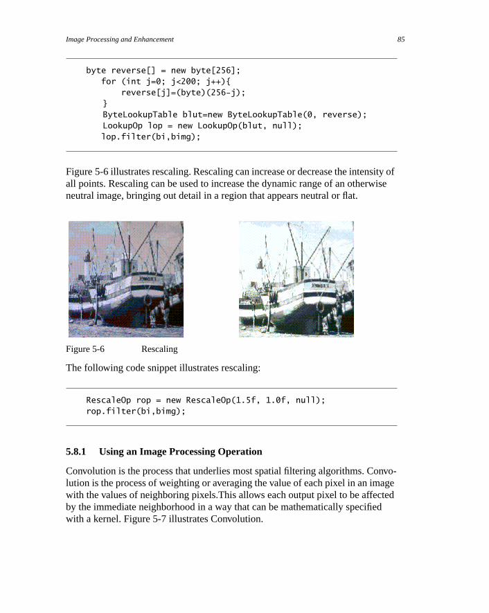
Image Processing and Enhancement 85
ity ofise
nvo-agetedd
byte reverse[] = new byte[256]; for (int j=0; j<200; j++){
reverse[j]=(byte)(256-j);}ByteLookupTable blut=new ByteLookupTable(0, reverse);LookupOp lop = new LookupOp(blut, null);
lop.filter(bi,bimg);
Figure 5-6 illustrates rescaling. Rescaling can increase or decrease the intensall points. Rescaling can be used to increase the dynamic range of an otherwneutral image, bringing out detail in a region that appears neutral or flat.
Figure 5-6 Rescaling
The following code snippet illustrates rescaling:
RescaleOp rop = new RescaleOp(1.5f, 1.0f, null);rop.filter(bi,bimg);
5.8.1 Using an Image Processing Operation
Convolution is the process that underlies most spatial filtering algorithms. Colution is the process of weighting or averaging the value of each pixel in an imwith the values of neighboring pixels.This allows each output pixel to be affecby the immediate neighborhood in a way that can be mathematically specifiewith a kernel. Figure 5-7 illustrates Convolution.

Imaging, JavaTM 2 SDK, Standard Edition, 1.3 Version86
inged
a-
Figure 5-7 Blurring with Convolution
The following code fragment illustrates how to use one of the image processclasses,ConvolveOp. In this example, each pixel in the source image is averagequally with the eight pixels that surround it.
float weight = 1.0f/9.0f;float[] elements = new float[9]; // create 2D array
// fill the array with nine equal elementsfor (i = 0; i < 9; i++) { elements[i] = weight;}// use the array of elements as argument to create a Kernelprivate Kernel myKernel = new Kernel(3, 3, elements);public ConvolveOp simpleBlur = new ConvolveOp(myKernel);
// sourceImage and destImage are instances of BufferedImagesimpleBlur.filter(sourceImage, destImage) // blur the image
The variablesimpleBlur contains a new instance ofConvolveOp that implementsa blur operation on aBufferedImage or aRaster. Suppose thatsourceImageanddestImage are two instances ofBufferedImage. When you callfilter, thecore method of theConvolveOp class, it sets the value of each pixel in the destintion image by averaging the corresponding pixel in the source image with theeight pixels that surround it.
The convolution kernel in this example could be represented by the followingmatrix, with elements specified to four significant figures:
K0.1111 0.1111 0.1111
0.1111 0.1111 0.1111
0.1111 0.1111 0.1111
=

Image Processing and Enhancement 87
e iswithel of
ithe in
hepleof its
xel
ensity
es,sian
e is
When an image is convolved, the value of each pixel in the destination imagcalculated by using the kernel as a set of weights to average the pixel’s valuethe values of surrounding pixels. This operation is performed on each channthe image.
The following formula shows how the weights in the kernel are associated wthe pixels in the source image when the convolution is performed. Each valuthe kernel is tied to a spatial position in the image.
The value of a destination pixel is the sum of the products of the weights in tkernel multiplied by the value of the corresponding source pixel. For many simoperations, the kernel is a matrix that is square and symmetric, and the sumweights adds up to one.2
The convolution kernel in this example is relatively simple. It weights each pifrom the source image equally. By choosing a kernel that weights the sourceimage at a higher or lower level, a program can increase or decrease the intof the destination image. TheKernel object, which is set in theConvolveOp con-structor, determines the type of filtering that is performed. By setting other valuyou can perform other types of convolutions, including blurring (such as Gausblur, radial blur, and motion blur), sharpening, and smoothing operations.Figure 5-8 illustrates sharpening using Convolution.
Figure 5-8 Sharpening with Convolution
The following code snippet illustrates sharpening with Convolution:
2. If the sum of the weights in the matrix is one, the intensity of the destination imagunchanged from the source.
Ki 1– j 1–, i j 1–, i 1+ j 1–,
i 1– j, i j, i 1+ j,i 1– j 1+, i j 1+, i 1+ j 1+,
=
Imaging, JavaTM 2 SDK, Standard Edition, 1.3 Version88
float[] elements = { 0.0f, -1.0f, 0.0f, -1.0f, 5.f, -1.0f, 0.0f, -1.0f, 0.0f};...
Kernel kernel = new Kernel(3,3,elements);ConvolveOp cop = new ConvolveOp(kernel, ConvolveOp.EDGE_NO_OP,
null);cop.filter(bi,bimg);
6
andPI
ree
r
o
et
Color
Color imaging is one of the fundamental components of any graphics system,it is often a source of great complexity in the imaging model. The Java 2D™ Aprovides support for high-quality color output that is easy to use and allowsadvanced clients to make sophisticated use of color.
The key color management classes in the Java 2D API areColorSpace, Color,ColorModel:
• A ColorSpace represents a system for measuring colors, typically using thseparate numerical values or components. TheColorSpace class containsmethods for converting between the color space and two standard colorspaces,CIEXYZ and RGB.
• A Color is a fixed color, defined in terms of its components in a particulaColorSpace. To draw aShape in a color, such as red, you pass aColor objectrepresenting that color to theGraphics2D context.Color is defined in thejava.awt package.
• A ColorModel describes a particular way that pixel values are mapped tcolors. AColorModel is typically associated with anImage orBufferedImage and provides the information necessary to correctly interprthe pixel values.ColorModel is defined in thejava.awt.image package.
6.1 Classes
Class Description
ColorSpace Identifies the color space of aColor object,Image, BufferedImage, orGraphicsDevice. Has methods to transform between RGB and CIEXYZcolor spaces.
89
Color, JavaTM 2 SDK, Standard Edition, 1.3 Version90
ingce. Itingata
ow
el
hatxel.
gs. A
ased
e.
6.2 Color Concepts
A ColorModel is used to interpret pixel data in an image. This includes mappcomponents in the bands of an image to components of a particular color spamight also involve extracting pixel components from packed pixel data, retrievmultiple components from a single band using masks, and converting pixel dthrough a lookup table.
To determine the color value of a particular pixel in an image, you need to knhow color information is encoded in each pixel. TheColorModel associated withan image encapsulates the data and methods necessary for translating a pixvalue to and from its constituent color components.
The Java 2D™ API provides two color models in addition to theDirectColor-
Model andIndexColorModel defined in the JDK 1.1 software release:
• ComponentColorModel can handle an arbitraryColorSpace and an array ofcolor components to match theColorSpace. This model can be used torepresent most color models on most types ofGraphicsDevices.
• PackedColorModel is a base class for models that represent pixel values thave their color components embedded directly in the bits of an integer piA PackedColorModel stores the packing information that describes howcolor and alpha components are extracted from the channel.TheDirectColorModel in the JDK 1.1 software release is aPackedColorModel.
6.2.0.1 ColorSpace
A ColorSpace object represents a system for measuring colors, typically usinthree separate numeric values. For example, RGB and CMYK are color space
ICC_ColorSpace Extends:ColorSpaceRepresents device-independent and device-dependent color spaces bon the ICC Profile Format Specification.
ICC_Profile A representation of color profile data for device independent and devicdependent color spaces based on the ICC Profile Format Specification
ICC_ProfileGray Extends:ICC_ProfileA representation of color space type gray.
ICC_ProfileRGB Extends:ICC_ProfileA representation of color space type RGB.
Class Description

Color Concepts 91
r
lor
g it
r
ofs
tween
er-ms,
in a
s thatersion
ColorSpace object serves as a colorspace tag that identifies the specific colospace of aColor object or, through aColorModel object, of anImage, Buffered-Image, orGraphicsConfiguration. ColorSpace provides methods that trans-form Colors in a specific color space to and fromsRGB and to and from a well-definedCIEXYZ color space.
All ColorSpace objects must be able to map a color from the represented cospace intosRGB and transform ansRGB color into the represented color space.Since everyColor contains aColorSpace object, set explicitly or by default,everyColor can also be converted tosRGB. EveryGraphicsConfiguration isassociated with aColorSpace object that in turn has an associatedColorSpace. Acolor specified in any color space can be displayed by any device by mappinthroughsRGB as an intermediate color space.
The methods used for this process aretoRGB andfromRGB:
• toRGB transforms aColor in the represented color space to aColor in sRGB.
• fromRGB takes aColor in sRGB and transforms it into the represented colospace.
Though mapping throughsRGB always works, it's not always the best solution.For one thing,sRGB cannot represent every color in the full gamut ofCIEXYZ col-ors. If a color is specified in some space that has a different gamut (spectrumrepresentable colors) thansRGB, then usingsRGB as an intermediate space resultin a loss of information. To address this problem, theColorSpace class can mapcolors to and from another color space, the “conversion space”CIEXYZ.
The methodstoCIEXYZ andfromCIEXYZ map color values from the representedcolor space to the conversion space. These methods support conversions beany two color spaces at a reasonably high degree of accuracy, oneColor at a time.However, it is expected that Java 2D API implementations will support high-pformance conversion based on underlying platform color-management systeoperating on entire images. (SeeColorConvertOp in “Imaging” on page 67.)
Figure 6-1 and Figure 6-2 illustrate the process of translating a color specifiedCMYK color space for display on an RGB color monitor. Figure 6-1 shows amapping throughsRGB. As this figure illustrates, the translation of the CMYKcolor to an RGB color is not exact because of a gamut mismatch.1
1. Of course, the colors used in these diagrams are illustrative, not accurate. The point icolors might not be mapped accurately between color spaces unless an appropriate convspace is used.

Color, JavaTM 2 SDK, Standard Edition, 1.3 Version92
e-drbi-d.
ofiles
a con-pping ICC
man-ith
Figure 6-1 Mapping Through sRGB
Figure 6-2 shows the same process usingCIEXYZ as the conversion space. WhenCIEXYZ is used, the color is passed through accurately.
Figure 6-2 Mapping Through CIEXYZ
6.2.0.2 ICC_Profile and ICC_ColorSpace
ColorSpace is actually an abstract class. The Java 2D API provides one implmentation,ICC_ColorSpace, which is based on ICC Profile data as representeby theICC_Profile class. You can define your own subclasses to represent atrary color spaces, as long as the methods discussed above are implementeHowever, most developers can simply use the defaultsRGB ColorSpace or colorspaces that are represented by commonly available ICC Profiles, such as prfor monitors and printers, or profiles embedded in image data.
“ColorSpace” on page 90 describes howColorSpace objects represent a colorspace and how colors in the represented space can be mapped to and from version space. Color management systems are often used to handle the mabetween color spaces. A typical color management system (CMS) managesprofiles, which are similar toColorSpace objects; ICC profiles describe an inputspace and a connection space, and define how to map between them. Coloragement systems are very good at figuring out how to map a color tagged wone profile into the color space of another profile.
toRGB
fromRGB
toCIEXYZ
fromCIEXYZ
CMYKColorSpace
toRGB
fromRGB
toCIEXYZ
fromCIEXYZ
DeviceRGBColorSpacesRGB
ColorCMYKColor
Device RGBColor
toRGB
fromRGB
toCIEXYZ
fromCIEXYZ
CMYKColorSpace
toRGB
fromRGB
toCIEXYZ
fromCIEXYZ
DeviceRGBColorSpaceCIEXYZ
ColorCMYKColor
Device RGBColor

Color Concepts 93
an
pes,
nnec-
can
An
RGB
s aon-ace
n-colorn.
m-
needs toen,
The Java 2D API defines a class calledICC_Profile that holds data for an arbi-trary ICC Profile.ICC_ColorSpace is an implementation of the abstractColor-
Space class.ICC_ColorSpace objects can be constructed fromICC_Profiles.(There are some limitations—not all ICC Profiles are appropriate for definingICC_ColorSpace).
ICC_Profile has several subclasses that correspond to specific color space tysuch asICC_ProfileRGB andICC_ProfileGray. Each subclass ofICC_Profilehas a well-defined input space (such as an RGB space) and a well-defined cotion space (likeCIEXYZ). The Java 2D API can use a platform's CMS to accesscolor profiles for various devices such as scanners, printers, and monitors. Italso use the CMS to find the best mapping between profiles.
6.2.1 Describing Colors
TheColor class provides a description of a color in a particular color space. instance ofColor contains the value of the color components and aColorSpace
object. Because aColorSpace object can be specified in addition to the colorcomponents when a new instance ofColor is created, theColor class can handlecolors in any color space.
TheColor class has a number of methods that support a proposed standardcolor space calledsRGB (seehttp://www.w3.org/pub/WWW/Graphics/Color/sRGB.html). sRGB is the default color space for the Java 2D API. Several con-structors defined by the Color class omit theColorSpace parameter. These con-structors assume that the color's RGB values are defined insRGB, and use a defaultinstance ofColorSpace to represent that space.
The Java 2D API usessRGB as a convenience to application programmers, not areference color space for color conversion. Many applications are primarily ccerned with RGB images and monitors, and defining a standard RGB color spmakes writing such applications easier. TheColorSpace class defines the meth-odstoRGB andfromRGB so that developers can easily retrieve colors in this stadard space. These methods are not intended to be used for highly accurate correction or conversions. See “ColorSpace” on page 90 for more informatio
To create a color in a color space other thansRGB, you use theColor constructorthat takes aColorSpace object and an array of floats that represent the color coponents appropriate to that space. TheColorSpace object identifies the colorspace.
To display a rectangle of a certain color, such as the process color cyan, youa way to describe this color to the system. There are a number of different waydescribe a color; for example, a color could be described as a set of red, gre
Color, JavaTM 2 SDK, Standard Edition, 1.3 Version94
led
ngr
essted.
Ks ofcyan
r.nd
rce.ntde-
d bydvel-
. Toentt
thatt
n-ail-
and blue (RGB) components, or a set of cyan, magenta, yellow, and black(CMYK) components. These different techniques for specifying colors are calcolor spaces.
As you probably know, colors on a computer screen are generated by blendidifferent amounts of red, green, and blue light. Therefore, using an RGB colospace is standard for imaging on computer monitors. Similarly, four-color procprinting uses cyan, magenta, yellow, and black ink to produce color on a prinpage; the printed colors are specified as percentages in a CMYK color space
Due to the prevalence of computer monitors and color printing, RGB and CMYcolor spaces are both commonly used to describe colors. However, both typecolor spaces have a fundamental drawback—they are device-dependent. Theink used by one printer might not exactly match the cyan ink used by anotheSimilarly, a color described as an RGB color might look blue on one monitor apurplish on another.
6.2.2 Mapping Colors through sRGB and CIEXYZ
The Java 2D API refers to RGB and CMYK as color space types. A particulamodel of monitor with its particular phosphors defines its own RGB color spaSimilarly, a particular model of printer has its own CMYK color space. DiffereRGB or CMYK color spaces can be related to each other through a device-inpendent color space.
Standards for the device-independent specification of color have been definethe International Commission on Illumination (CIE). The most commonly usedevice-independent color space is the three-component XYZ color space deoped by CIE. When you specify a color usingCIEXYZ, you are insulated fromdevice dependencies.
Unfortunately, it’s not always practical to describe colors in theCIEXYZ colorspace—there are valid reasons for representing colors in other color spacesobtain consistent results when a color is represented using a device-dependcolor space such as a particular RGB space, it is necessary to show how thaRGB space relates to a device-independent space likeCIEXYZ.
One way to map between color spaces is to attach information to the spacesdescribes how the device-dependent space relates to the device-independenspace. This additional information is called aprofile. A commonly used type ofcolor profile is the ICC Color Profile, as defined by the International Color Cosortium. For details, see the ICC Profile Format Specification, version 3.4 avable athttp://www.color.org.

Color Concepts 95
Javae in
n anacter-uce
.
tputlordent Inphi-d to a
Figure 6-3 illustrates how a solid color and a scanned image are passed to the2D API, and how they are displayed by various output devices. As you can seFigure 6-3, both the input color and the image have profiles attached.
Figure 6-3 Using Profiles to Map Between Color Spaces
6.2.2.1 Color Matching
Once the API has an accurately specified color, it must reproduce that color ooutput device, such as a monitor or printer. These devices have imaging charistics of their own that must be taken into account to make sure that they prodthe correct results. Another profile is associated with each output device todescribe how the colors need to be transformed to produce accurate results
Achieving consistent and accurate color requires that both input colors and oudevices be profiled against a standard color space. For example, an input cocould be mapped from its original color space into a standard device-indepenspace, and then mapped from that space to the output device’s color space.many respects, the transformation of colors mimics the transformation of gracal objects in an (x, y) coordinate space. In both cases, a transformation is usespecify coordinates in a “standard” space and then map those coordinates todevice-specific space for output.
Profile RGBMonitor
GrayscaleMonitor
CMYKPrinter
Java 2D
Solid Color
Scanned Image
Profile
Profile
Profile
ProfileAPI

Color, JavaTM 2 SDK, Standard Edition, 1.3 Version96

7
d
der
rsare
urethe
Printing
The Java Printing API enables applications to:
• Print all AWT and Java 2D™ graphics, including composited graphics animages.
• Control document-composition functions such as soft collating, reverse orprinting, and booklet printing.
• Invoke printer-specific functions such as duplex (two-sided) printing andstapling.
• Print on all platforms, including Windows and Solaris. This includes printedirectly attached to the computer as well as those that the platform softwis able to access using network printing protocols.
Not all of these features are supported in the Java™ 2 SDK Printing API andimplementation. The API will be extended to support all of these features in futreleases. For example, additional printer controls will be added by augmentingset of named properties of a print job that the application can control.
97

Printing, JavaTM 2 SDK, Standard Edition, 1.3 Version98
pro-sks
hane able
age
e
age
he
age
nt
7.1 Interfaces and Classes
7.2 Printing Concepts
The Java Printing API is based on acallbackprinting model in which the printingsystem, not the application, controls when pages are printed. The applicationvides information about the document to be printed and the printing system athe application to render each page as it needs them.
The printing system might request that a particular page be rendered more tonce or request that pages be rendered out of order. The application must bto generate the proper page image, no matter which page the printing systemrequests. In this respect, the printing system is similar to the window toolkit,which can request components to repaint at any time, in any order.
Interface Description
Printable ThePrintable interface is implemented by eachpage painter, the applicationclass(es) called by the printing system to render a page. The system calls the ppainter’sprint method to request that a page be rendered.
Pageable ThePageable interface is implemented by a document that is to be printed by thprinting system. Through thePageable methods, the system can determine thenumber of pages in the document, the format to use for each page, and the ppainter to use to render each page.
PrinterGraphics TheGraphics2D objects that a page painter uses to render a page implement tPrinterGraphics interface. This enables an application to get thePrinterJob
object that is controlling the printing.
Class Description
Book Implements:PageableRepresents a document in which pages can have different page formats and ppainters. This class uses thePageable interface to interact with aPrinterJob.
PageFormat Describes the size and orientation of a page to be printed, as well as thePaper
used to print it. For example,portrait andlandscape paper orientations are rep-resented byPageFormat.
Paper Describes the physical characteristics of a piece of paper.
PrinterJob The principal class that controls printing. The application callsPrinterJob
methods to set up a job, display a print dialog to the user (optional), and to prithe pages in the job.

Printing Concepts 99
nrs.stemack is
tersthis
ided ten
hen
intion
gs
thees a
The callback printing model is more flexible than traditional application-driveprinting models and supports printing on a wider range of systems and printeFor example, if a printer stacks output pages in reverse order, the printing sycan ask the application to generate pages in reverse order so that the final stin proper reading order.
This model also enables applications to print to a bitmap printer from computhat don’t have enough memory or disk space to buffer a full-page bitmap. Insituation, a page is printed as a series of small bitmaps orbands. For example, ifonly enough memory to buffer one tenth of a page is available, the page is divinto ten bands. The printing system asks the application to render each pagetimes, once to fill each band. The application does not need to be aware of tnumber or size of the bands; it simply must be able to render each page wherequested.
7.2.1 Supporting Printing
An application has to perform two tasks to support printing:
• Job control—initiating and managing the print job.
• Imaging—rendering each page when the printing system requests it.
7.2.1.1 Job Control
The user often initiates printing by clicking a button or selecting a menu iteman application. When a print operation is triggered by the user, the applicacreates aPrinterJob object and uses it to manage the printing process.
The application is responsible for setting up the print job, displaying print dialoto the user, and starting the printing process.
7.2.1.2 Imaging
When a document is printed, the application has to render each page when printing system requests it. To support this mechanism, the application providpage painterthat implements thePrintable interface. When the printing systemneeds a page rendered, it calls the page painter’sprint method.
When a page painter’sprint method is called, it is passed aGraphics context touse to render the page image. It is also passed aPageFormat object that specifiesthe geometric layout of the page, and an integerpage indexthat identifies the ordi-nal position of the page in the print job.

Printing, JavaTM 2 SDK, Standard Edition, 1.3 Version100
iffer-
d
text
g
h.
oless
coor-d so
nire
The printing system supports bothGraphics andGraphics2D rendering, To printJava 2D™Shapes, Text, andImages, you cast theGraphics object passed intotheprint method to aGraphics2D.
To print documents in which the pages use different page painters and have dent formats, you use apageable job. To create a pageable job, you can use theBook class or your own implementation of thePageable interface. To implementsimple printing operations, you do not need to use a pageable print job;Print-
able can be used as long as all of the pages share the same page format anpainter.
7.2.2 Page Painters
The principal job of a page painter is to render a page using the graphics conthat is provided by the printing system. A page painter implements thePrint-
able.print method:
public int print(Graphics g, PageFormat pf, int pageIndex)
The graphics context passed to theprint method is either an instance ofGraph-
ics or Graphics2D, depending on the packages loaded in your Java VirtualMachine. To useGraphics2D features, you can cast theGraphics object to aGraphics2D. TheGraphics instance passed toprint also implements thePrint-erGraphics interface.
ThePageFormat passed to aPrintable describes the geometry of the page beinprinted. The coordinate system of the graphics context passed toprint is fixed tothe page: the origin of the coordinate system is at the upper left corner of thepaper,X increases to the right,Y increases downward, and the units are 1/72 incIf the page is in portrait orientation, the x-axis aligns with the paper’s “width,”while the y-axis aligns with the paper’s “height.” (Normally, but not always, apaper’s height exceeds its width.) If the page is in landscape orientation, the rare reversed: the x-axis aligns with the paper’s “height” and the y-axis with it“width.”
Because many printers cannot print on the entire paper surface, thePageFormat
specifies theimageable area of the page: this is the portion of the page in whichit’s safe to render. The specification of the imageable area does not alter thedinate system; it is provided so that the contents of the page can be renderethat they don’t extend into the area where the printer can’t print.
The graphics context passed toprint has a clip region that describes the portioof the imageable area that should be drawn. It is always safe to draw the entpage into the context; the printing system will handle the necessary clipping.

Printing Concepts 101
t be get
.
es
he
pageerald, the
use
Forinterat
ent
rongd.
However, to eliminate the overhead of drawing portions of the page that won’printed, you can use the clipping region to limit the areas that you render. Tothe clipping region from the graphics context, callGraphics.getClip. You arestrongly encouraged to use the clip region to reduce the rendering overhead
It is sometimes desirable to launch the entire printing operation “in the back-ground” so that a user can continue to interact with the application while pagare being rendered. To do this, callPrinterJob.print in a separate thread.
If possible, you should avoid graphics operations that require knowledge of tprevious image contents, such ascopyArea, setXOR, and compositing. Theseoperations can slow rendering and the results might be inconsistent.
7.2.3 Printable Jobs and Pageable Jobs
A Printable job provides the simplest way to print. Only one page painter isused; the application provides a single class that implements thePrintable inter-face. When it’s time to print, the printing system calls the page painter’sprint
method to render each page. The pages are requested in order, starting withindex 0. However, the page painter might be asked to render each page sevtimes before it advances to the next page. When the last page has been printepage painter’s print method returns NO_SUCH_PAGE.
In aPrintable job:
• All pages use the same page painter andPageFormat. If a print dialog ispresented, it will not display the number of pages in the document becathat information is not available to the printing system.
• The printing system always asks the page painter to print each page inindexed order, starting with the page at index 0. No pages are skipped. example, if a user asks to print pages 2 and 3 of a document, the page pawill be called with indices 0, 1, and 2. The printing system might request tha page be rendered multiple times before moving to the next page.
• The page painter informs the printing system when the end of the documhas been reached.
• All page painters are called in the same thread.
• Some printing systems might not be able to achieve the ideal output. Foexample, the stack of pages emerging from the printer might be in the wrorder, or the pages might not be collated if multiple copies are requeste
A Pageable job is more flexible than aPrintable job. Unlike the pages in aPrintable job, pages in aPageable job can differ in layout and implementation.
Printing, JavaTM 2 SDK, Standard Edition, 1.3 Version102
e a
rderagesand
he
tingving
entand
-
rint
heand
inter
To manage aPageable job, you can use theBook class or implement your ownPageable class. Through thePageable, the printing system can determine thenumber of pages to print, the page painter to use for each page, and thePageFor-
mat to use for each page. Applications that need to print documents that havplanned structure and format should usePageable jobs.
In aPageable job:
• Different pages can use different page painters andPageFormats.
• The printing system can ask page painters to print pages in an arbitrary oand some pages might be skipped. For example, if a user asks to print p2 and 3 of a document, the page painter will be called with indices 1 and 2page index 0 will be skipped.
• Pageable jobs do not need to know in advance how many pages are in tdocument. However, unlikePrintable jobs, they must be able to renderpages in any order. There might be gaps in the sequencing and the prinsystem might request that a page be rendered multiple times before moto the next page. For example, a request to print pages 2 and 3 of a docummight result in a sequence of calls that request pages with indices 2,2,1,1,1.
7.2.4 Typical Life-Cycle of a PrinterJob
An application steers thePrinterJob object through a sequence of steps to complete a printing job. The simplest sequence used by an application is:
1. Get a newPrinterJob object by callingPrinterJob.getPrinterJob.
2. Determine whatPageFormat to use for printing. A defaultPageFormat canbe obtained by callingdefaultPage or you can invokepageDialog to presenta dialog box that allows the user to specify a format.
3. Specify the characteristics of the job to be printed to thePrinterJob. For aPrintable job, call setPrintable; for a Pageable job, call setPageable.Note that aBook object is ideal for passing tosetPageable.
4. Specify additional print job properties, such as the number of copies to por the name of the job to print on the banner page.
5. Call printDialog to present a dialog box to the user. This is optional. Tcontents and appearance of this dialog can vary across different platformsprinters. On most platforms, the user can use this dialog to change the prselection. If the user cancels the print job, theprintDialog method returns
Printing Concepts 103
s
g
s
pli-ons,ay a A
you
FALSE.
6. CallPrinterjob.print to print the job. This method in turn callsprint onthe appropriate page painters.
A job can be interrupted during printing if:
• A PrinterException is thrown—the exception is caught by theprint
method and the job is halted. A page painter throws aPrinterException ifit detects a fatal error.
• PrinterJob.cancel is called—the printing loop is terminated and the job icanceled. Thecancel method can be called from a separate thread thatdisplays a dialog box and allows the user to cancel printing by clicking abutton in the box.
Pages generated before a print job is stopped might or might not be printed.
The print job is usually not finished when theprint method returns. Work is typ-ically still being done by a printer driver, print server, or the printer itself. Thestate of thePrinterJob object might not reflect the state of the actual job beinprinted.
Because the state of aPrinterJob changes during its life cycle, it is illegal toinvoke certain methods at certain times. For example, callingsetPageable afteryou’ve calledprint makes no sense. When illegal calls are detected, thePrint-
erJob throws ajava.lang.IllegalStateException.
7.2.5 Dialogs
The Java Printing API requires that applications invoke user-interface dialogexplicitly. These dialogs might be provided by the platform software (such asWindows) or by a Java™ 2 SDK software implementation. For interactive apcations, it is customary to use such dialogs. For production printing applicatihowever, dialogs are not necessary. For example, you wouldn’t want to displdialog when automatically generating and printing a nightly database report.print job that requires no user interaction is sometimes called asilent print job.
7.2.5.1 Page setup dialog
You can allow the user to alter the page setup information contained in aPage-
Format by displaying a page setup dialog. To display the page setup dialog, call PrinterJob.pageDialog. The page setup dialog is initialized using the

Printing, JavaTM 2 SDK, Standard Edition, 1.3 Version104
hen
u
on
er
parameter passed topageDialog. If the user clicks the OK button in the dialog,thePageFormat instance is cloned, altered to reflect the user’s selections, and treturned. If the user cancels the dialog,pageDialog returns the original unalteredPageFormat.
7.2.5.2 Print dialog
Typically, an application presents a print dialog to the user when a print menitem or button is activated. To display this print dialog, you call thePrinterJob’s
printDialog method. The user’s choices in the dialog are constrained basedthe number and format of the pages in thePrintable or Pageable that have beenfurnished to thePrinterJob. If the user clicks OK in the print dialog,printDia-log returnsTRUE. If the user cancels the print dialog,FALSE is returned and theprint job should be considered abandoned.
7.3 Printing with Printables
To provide basic printing support:
1. Implement thePrintable interface to provide a page painter that can rendeach page to be printed.
2. Create aPrinterJob.
3. CallsetPrintable to tell thePrinterJob how to print your document.
4. Callprint on thePrinterJob object to start the job.
In the following example, aPrintable job is used to print five pages, each ofwhich displays a green page number. Job control is managed in themain method,which obtains and controls thePrinterJob. Rendering is performed in the pagepainter’sprint method.
import java.awt.*; import java.awt.print.*;public class SimplePrint implements Printable{private static Font fnt = new Font("Helvetica",Font.PLAIN,24);
public static void main(String[] args) { // Get a PrinterJob PrinterJob job = PrinterJob.getPrinterJob();

Printing with Printables 105
t
radi-
// Specify the Printable is an instance of SimplePrint job.setPrintable(new SimplePrint()); // Put up the dialog box if (job.printDialog()) { // Print the job if the user didn't cancel printing try { job.print(); } catch (Exception e) { /* handle exception */ } } System.exit(0); }
public int print(Graphics g, PageFormat pf, int pageIndex) throws PrinterException { // pageIndex 0 to 4 corresponds to page numbers 1 to 5. if (pageIndex >= 5) return Printable.NO_SUCH_PAGE; g.setFont(fnt); g.setColor(Color.green); g.drawString("Page " + (pageIndex+1), 100, 100); return Printable.PAGE_EXISTS; }}
7.3.1 Using Graphics2D for Rendering
You can invokeGraphics2D functions in you page painter’s print method by firscasting theGraphics context to aGraphics2D.
In the following example, the page numbers are rendered using a red-green gent. To do this, aGradientPaint is set in theGraphics2D context.
import java.awt.*; import java.awt.print.*;public class SimplePrint2D implements Printable{private static Font fnt = new Font("Helvetica",Font.PLAIN,24);
private Paint pnt = new GradientPaint(100f, 100f, Color.red, 136f, 100f, Color.green, true);
public static void main(String[] args) {
Printing, JavaTM 2 SDK, Standard Edition, 1.3 Version106
ge, it
d the time
ldta.
le
ren-
// Get a PrinterJob PrinterJob job = PrinterJob.getPrinterJob(); // Specify the Printable is an instance of SimplePrint2D job.setPrintable(new SimplePrint2D()); // Put up the dialog box if (job.printDialog()) { // Print the job if the user didn't cancel printing try { job.print(); } catch (Exception e) { /* handle exception */ } } System.exit(0); }
public int print(Graphics g, PageFormat pf, int pageIndex) throws PrinterException { // pageIndex 0 to 4 corresponds to page numbers 1 to 5. if (pageIndex >= 5) return Printable.NO_SUCH_PAGE; Graphics2D g2 = (Graphics2D) g; // Use the font defined above g2.setFont(fnt); // Use the gradient color defined above g2.setPaint(pnt); g2.drawString("Page " + (pageIndex+1), 100f, 100f); return Printable.PAGE_EXISTS; }}
7.3.2 Printing a File
When a page painter’s print method is invoked several times for the same pamust generate the same output each time.
There are many ways to ensure that repeated requests to render a page yielsame output. For example, to ensure that the same output is generated eachthe printing system requests a particular page of a text file, page painter coueither store and reuse file pointers for each page or store the actual page da
In the following example, a “listing” of a text file is printed. The name of the fiis passed as an argument to themain method. ThePrintListingPainter classstores the file pointer in effect at the beginning of each new page it is asked to

Printing with Printables 107
mem-
der. When the same page is rendered again, the file pointer is reset to the rebered position.import java.awt.*;import java.awt.print.*;import java.io.*;
public class PrintListing{ public static void main(String[] args) { // Get a PrinterJob PrinterJob job = PrinterJob.getPrinterJob(); // Ask user for page format (e.g., portrait/landscape) PageFormat pf = job.pageDialog(job.defaultPage()); // Specify the Printable is an instance of // PrintListingPainter; also provide given PageFormat job.setPrintable(new PrintListingPainter(args[0]), pf); // Print 1 copy job.setCopies(1); // Put up the dialog box if (job.printDialog()) { // Print the job if the user didn't cancel printing try { job.print(); } catch (Exception e) { /* handle exception */ } } System.exit(0); }}
class PrintListingPainter implements Printable{ private RandomAccessFile raf; private String fileName; private Font fnt = new Font("Helvetica", Font.PLAIN, 10); private int rememberedPageIndex = -1; private long rememberedFilePointer = -1; private boolean rememberedEOF = false;
public PrintListingPainter(String file) { fileName = file; try
Printing, JavaTM 2 SDK, Standard Edition, 1.3 Version108
{ // Open file raf = new RandomAccessFile(file, "r"); } catch (Exception e) { rememberedEOF = true; } }
public int print(Graphics g, PageFormat pf, int pageIndex) throws PrinterException { try { // For catching IOException if (pageIndex != rememberedPageIndex) { // First time we've visited this page rememberedPageIndex = pageIndex; // If encountered EOF on previous page, done if (rememberedEOF) return Printable.NO_SUCH_PAGE; // Save current position in input file rememberedFilePointer = raf.getFilePointer(); } else raf.seek(rememberedFilePointer); g.setColor(Color.black); g.setFont(fnt);
int x = (int) pf.getImageableX() + 10;int y = (int) pf.getImageableY() + 12;
// Title line g.drawString("File: " + fileName + ", page: " + (pageIndex+1), x, y); // Generate as many lines as will fit in imageable area y += 36;
while (y + 12 < pf.getImageableY()+pf.getImageableHeight()) { String line = raf.readLine(); if (line == null) { rememberedEOF = true; break;
} g.drawString(line, x, y); y += 12; } return Printable.PAGE_EXISTS; } catch (Exception e) { return Printable.NO_SUCH_PAGE;}
Printing with Pageables and Books 109
f a
bethe
hare
ienta-
ame
rns
Theation
ll
}}
7.4 Printing with Pageables and Books
Pageable jobs are suited for applications that build an explicit representation odocument, page by page. TheBook class is a convenient way to usePageables,but you can also build your ownPageable structures ifBook does not suit yourneeds. This section shows you how to useBook.
Although slightly more involved,Pageable jobs are preferred overPrintablejobs because the printing system has more flexibility. A major advantage ofPage-
ables is that the number of pages in the document is usually known and candisplayed to the user in the print dialog box. This helps the user to confirm thatjob is specified correctly or to select a range of pages for printing.
A Book represents a collection of pages. The pages in a book do not have to sthe same size, orientation, or page painter. For example, aBook might contain twoletter size pages in portrait orientation and a letter size page in landscape ortion.
When aBook is first constructed, it is empty. To add pages to aBook, you use theappend method. This method takes aPageFormat object that defines the page’ssize, printable area, and orientation and a page painter that implements thePrintable interface.
Multiple pages in aBook can share the same page format and painter. Theappend
method is overloaded to enable you to add a series of pages that have the sattributes by specifying a third parameter, the number of pages.
If you don’t know the total number of pages in aBook, you can passUNKNOWN_NUMBER_OF_PAGES to theappend method. The printing system will thencall your page painters in order of increasing page index until one of them retuNO_SUCH_PAGE.
ThesetPage method can be used to change a page’s page format or painter.page to be changed is identified by a page index that indicates the page’s locin theBook.
You callsetPageable and pass in theBook to prepare the print job. ThesetPage-able andsetPrintable methods are mutually exclusive; that is, you should caone or the other but not both when preparing thePrinterJob.
Printing, JavaTM 2 SDK, Standard Edition, 1.3 Version110
7.4.1 Using a Pageable Job
In the following example, aBook is used to reproduce the first simple printingexample. (Because this case is so simple, there is little benefit in using aPageable
job instead of aPrintable job, but it illustrates the basics of using aBook.) Notethat you still have to implement thePrintable interface and perform page ren-dering in the page painter’sprint method.
import java.awt.*;import java.awt.print.*;
public class SimplePrintBook implements Printable{private static Font fnt = new Font("Helvetica",Font.PLAIN,24);
public static void main(String[] args) { // Get a PrinterJob PrinterJob job = PrinterJob.getPrinterJob(); // Set up a book Book bk = new Book();
bk.append(new SimplePrintBook(), job.defaultPage(), 5); // Pass the book to the PrinterJob job.setPageable(bk); // Put up the dialog box if (job.printDialog()) { // Print the job if the user didn't cancel printing try { job.print(); } catch (Exception e) { /* handle exception */ } } System.exit(0); }
public int print(Graphics g, PageFormat pf, int pageIndex) throws PrinterException { g.setFont(fnt); g.setColor(Color.green); g.drawString("Page " + (pageIndex+1), 100, 100); return Printable.PAGE_EXISTS; }}

Printing with Pageables and Books 111
ere and
7.4.2 Using Multiple Page Painters
In the following example, two different page painters are used: one for a covpage and one for content pages. The cover page is printed in landscape modthe contents pages are printed in portrait mode.
import java.awt.*;import java.awt.print.*;
public class PrintBook{ public static void main(String[] args) { // Get a PrinterJob PrinterJob job = PrinterJob.getPrinterJob(); // Create a landscape page format PageFormat pfl = job.defaultPage(); pfl.setOrientation(PageFormat.LANDSCAPE); // Set up a book Book bk = new Book(); bk.append(new PaintCover(), pfl); bk.append(new PaintContent(), job.defaultPage(), 2); // Pass the book to the PrinterJob job.setPageable(bk); // Put up the dialog box if (job.printDialog()) { // Print the job if the user didn't cancel printing try { job.print(); } catch (Exception e) { /* handle exception */ } } System.exit(0); }}
class PaintCover implements Printable{ Font fnt = new Font("Helvetica-Bold", Font.PLAIN, 72);
public int print(Graphics g, PageFormat pf, int pageIndex) throws PrinterException { g.setFont(fnt); g.setColor(Color.black);
Printing, JavaTM 2 SDK, Standard Edition, 1.3 Version112
int yc = (int) (pf.getImageableY() + pf.getImageableHeight()/2); g.drawString("Widgets, Inc.", 72, yc+36); return Printable.PAGE_EXISTS; }}class PaintContent implements Printable{ public int print(Graphics g, PageFormat pf, int pageIndex) throws PrinterException { Graphics2D g2 = (Graphics2D) g; int useRed = 0; int xo = (int) pf.getImageableX();
int yo = (int) pf.getImageableY();// Fill page with circles or squares, alternating red & greenfor (int x = 0; x+28 < pf.getImageableWidth(); x += 36)
for (int y = 0; y+28 < pf.getImageableHeight(); y += 36) { if (useRed == 0) g.setColor(Color.red); else g.setColor(Color.green); useRed = 1 - useRed;
if (pageIndex % 2 == 0) g.drawRect(xo+x+4, yo+y+4, 28, 28); else g.drawOval(xo+x+4, yo+y+4, 28, 28); } return Printable.PAGE_EXISTS; }}